Embed Size (px)
Citation preview
1 20.06.18 en / 995
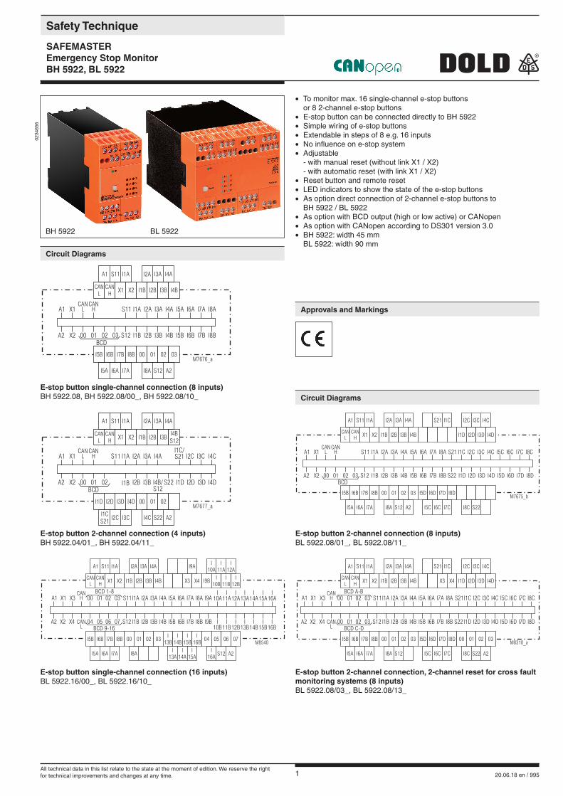
Safety Technique
SAFEMASTEREmergency Stop MonitorBH 5922, BL 5922
• To monitor max. 16 single-channel e-stop buttons or 8 2-channel e-stop buttons• E-stop button can be connected directly to BH 5922• Simple wiring of e-stop buttons• Extendable in steps of 8 e.g. 16 inputs• No influence on e-stop system• Adjustable - with manual reset (without link X1 / X2) - with automatic reset (with link X1 / X2)• Reset button and remote reset• LED indicators to show the state of the e-stop buttons• As option direct connection of 2-channel e-stop buttons to BH 5922 / BL 5922• As option with BCD output (high or low active) or CANopen • As option with CANopen according to DS301 version 3.0• BH 5922: width 45 mm BL 5922: width 90 mm
0234
656
E-stop button single-channel connection (8 inputs)BH 5922.08, BH 5922.08/00_, BH 5922.08/10_
E-stop button 2-channel connection (4 inputs)BH 5922.04/01_, BH 5922.04/11_
E-stop button 2-channel connection (8 inputs)BL 5922.08/01_, BL 5922.08/11_
E-stop button 2-channel connection, 2-channel reset for cross fault monitoring systems (8 inputs)BL 5922.08/03_, BL 5922.08/13_
A1
CANL
CANH
X1 X2 I1B I2B I3B I4B
S11 I1A I2A I3A I4A
I5B I6B I7B I8B 00 01 02 03
I5A I6A I7A I8A S12 A2
A1 X1 S11 I1A I2A I3A I4A I5A I6A I7A I8ACAN
LCAN
H
A2 X2 00 01 02 03 S12 I1B I2B I3B I4B I5B I6B I7B I8BBCD
M7676_a
A1
CANL
CANH
X1 X2 I1B I2B I3BI4BS12
S11 I1A I2A I3A I4A
I1D I2D I3D I4D 00 01 02
I1CS21
I2C I3C I4C S22 A2
M7677_a
A1 X1 S11 I1A I2A I3A I4AI1C/S21 I2C I3C I4C
CANL
CANH
A2 X2 00 01 02 I1B I2B I3B I4B/S12
S22 I1D I2D I3D I4DBCD
A1
A1 X1 S11 I1A I2A I3A I4A I5A I6A I7A I8A S21 I1C I2C I3C I4C I5C I6C I7C I8CCAN
LCAN
H
A2 X2 00 01 02 03 S12 I1B I2B I3B I4B I5B I6B I7B I8B S22 I1D I2D I3D I4D I5D I6D I7D I8DBCD
CANL
CANH
X1 X2 I1B I2B I3B I4B I1D I2D I3D I4D
I5B I6B I7B I8B 00 01 02 03 I5D I6D I7D I8D
S11 I1A I2A I3A I4A S21 I1C I2C I3C I4C
I5A I6A I7A I8A S12 A2 I5C I6C I7C I8C S22
M7675_b
A1
A1 X1 X3 S11I1A I2A I3A I4A I5A I6A I7A I8A S21I1C I2C I3C I4C I5C I6C I7C I8C
CANL
CANH
A2 X2 X4 00
00
01
01
02
02
03
03
S12 I1B I2B I3B I4B I5B I6B I7B I8B S22 I1D I2D I3D I4D I5D I6D I7D I8DBCD C-D
BCD A-B
CANL
CANH
X1 X2 I1B I2B I3B I4B X3 X4 I1D I2D I3D I4D
I5B I6B I7B I8B 00 0001 0102 0203 03I5D I6D I7D I8D
S11 I1A I2A I3A I4A S21 I1C I2C I3C I4C
I5A I6A I7A I8A S12 A2I5C I6C I7C I8C S22
M8310_a
A1
A1 X1 X3 S11I1A I2A I3A I4A I5A I6A I7A I8A I9AI
10AI
11AI
12AI
13AI
14AI
15AI
16A
CANL
CANH
A2 X2 X4 04
00
05
01
06
02
07
03
S12 I1B I2B I3B I4B I5B I6B I7B I8B I9BBCD 9-16
BCD 1-8
CANL
CANH
X1 X2 I1B I2B I3B I4B X3 X4 I9BI
10BI
11BI
12B
I5B I6B I7B I8B 00 0401 0502 0603 07I
13BI
14BI
15BI
16B
S11 I1A I2A I3A I4A I9AI
10AI
11AI
12A
I5A I6A I7A I8A A2I
13AI
14AI
15AI
16AS12
M8540
I10B
I11B
I12B
I13B
I14B
I15B
I16B
E-stop button single-channel connection (16 inputs)BL 5922.16/00_, BL 5922.16/10_
BH 5922 BL 5922
Circuit Diagrams
Circuit Diagrams
Approvals and Markings
All technical data in this list relate to the state at the moment of edition. We reserve the rightfor technical improvements and changes at any time.
2 20.06.18 en / 995
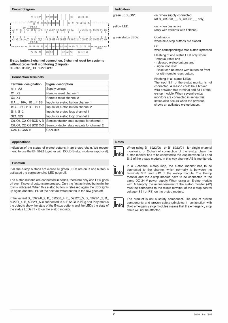
E-stop button 2-channel connection, 2-channel reset for systems without cross fault monitoring (8 inputs)BL 5922.08/02_, BL 5922.08/12
A1
A1 X1 X3 S11I1A I2A I3A I4A I5A I6A I7A I8A I1C I2C I3C I4C I5C I6C I7C I8C
CANL
CANH
A2 X2 X4 00
00
01
01
02
02
03
03
S12 I1B I2B I3B I4B I5B I6B I7B I8B S22 I1D I2D I3D I4D I5D I6D I7D I8DBCD C-D
BCD A-B
CANL
CANH
X1 X2 I1B I2B I3B I4B X3 X4 I1D I2D I3D I4D
I5B I6B I7B I8B 00 0001 0102 0203 03I5D I6D I7D I8D
S11 I1A I2A I3A I4A I1C I2C I3C I4C
I5A I6A I7A I8A S12 A2I5C I6C I7C I8C S22
M8523
Indication of the status of e-stop buttons in an e-stop chain. We recom-mend to use the BH 5922 together with DOLD E-stop modules (approval).
If all the e-stop buttons are closed all green LEDs are on. If one button is activated the corresponding LED goes off.
The e-stop buttons are connected in series, therefore only one LED goes off even if several buttons are pressed. Only the first activated button in the row is indicated. When this e-stop button is released again the LED lights up again and the LED of the next activated button in the row goes off.
If the variant B_ 5922/0_2, B_ 5922/0_4, B_ 5922/0_5, B_ 5922/1_2, B_ 5922/1_4, B_5922/1_5 is connected to a IP 5503 in Plug and Play modus the outputs show the state of the E-stop buttons and the LEDs the state of the status LEDs Ι1 - Ι8 on the e-stop monitor.
green LED „ON“: on, when supply connected (at B_ 5922/0_ _, B_ 5922/1_ _ only)
yellow LED: on, when bus active (only with variants with fieldbus)
green status LEDs: Continuous: when all e-stop buttons are closed
Off: when corresponding e-stop button is pressed
Flashing of one status LED only when: - manual reset and - released e-stop buttons and - signal not reset Reset can be made with button on front or with remote reset-button.
Flashing of all status LEDs: The input S11 of the e-stop monitor is not connected. A reason could be a broken wire between this terminal and S11 of the e-stop module. When several e-stop monitors are connected in series this status also occurs when the previous shows an activated e-stop button.
nfo When using B_ 5922/00_ or B_ 5922/01_ for single channel
monitoring or 2-channel connection of the e-stop chain the e-stop monitor has to be conected to the loop between S11 and S12 of the e-stop module. In this way channel AB is monitored.
nfo In a 2-channel e-stop loop, the e-stop monitor has to be
connected to the channel which normally is between the terminals S11 and S12 of the e-stop module. The E-stop monitor and the e-stop module have to be connected to the same DC 24 V power supply. When using an E-stop module with AC-supply the minus-terminal of the e-stop monitor (A2) must be connected to the minus-terminal of the e-stop control voltage (S21 or PE) on the e-stop module.
nfo The product is not a safety component. The use of proven
components and proven safety principles in conjunction with Dold emergency stop modules means that the emergency stop chain will not be affected.
Indicators
NotesApplications
Function
Terminal designation Signal descriptionA1+, A2 Supply voltage
X1, X2 Remote reset channel 1
X3, X4 Remote reset channel 2
I1A ... I16A, I1B ... I16B Inputs for e-stop button channel 1
I1C ... I8C, I1D ... I8D Inputs for e-stop button channel 2
S11, S12 Inputs for e-stop loop channel 1
S21, S22 Inputs for e-stop loop channel 2
O0, O1, O2, O3 BCD A-B Semiconductor state outputs for channel 1
O0, O1, O2, O3 BCD C-D Semiconductor state outputs for channel 2
CAN L, CAN H CAN-Bus
Connection Terminals
Circuit Diagram
3 20.06.18 en / 995
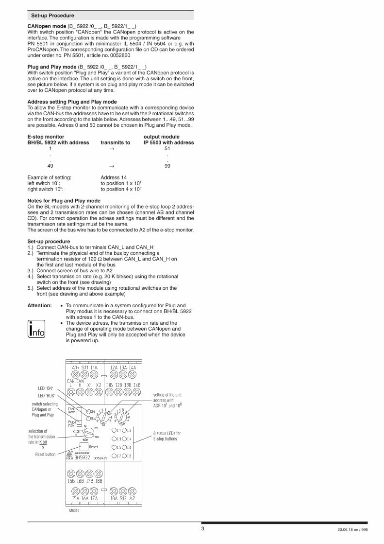
CANopen mode (B_ 5922 /0_ _, B_ 5922/1_ _)With switch position "CANopen" the CANopen protocol is active on the interface. The configuration is made with the programming software PN 5501 in conjunction with minimaster IL 5504 / IN 5504 or e.g. with ProCANopen. The corresponding configuration file on CD can be ordered under order no. PN 5501, article no. 0052860
Plug and Play mode (B_ 5922 /0_ _, B_ 5922/1_ _)With switch position "Plug and Play" a variant of the CANopen protocol is active on the interface. The unit setting is done with a switch on the front, see picture below. If a system is on plug and play mode it can be switched over to CANopen protocol at any time.
Address setting Plug and Play modeTo allow the E-stop monitor to communicate with a corresponding device via the CAN-bus the addresses have to be set with the 2 rotational switches on the front according to the table below. Adresses between 1...49, 51...99 are possible. Adress 0 and 50 cannot be chosen in Plug and Play mode.
E-stop monitor output moduleBH/BL 5922 with address transmits to IP 5503 with address 1 → 51 . . . . 49 → 99
Example of setting: Address 14left switch 101: to position 1 x 101
right switch 100: to position 4 x 100
Notes for Plug and Play modeOn the BL-models with 2-channel monitoring of the e-stop loop 2 addres-sees and 2 transmission rates can be chosen (channel AB and channel CD). For correct operation the adress settings must be different and the transmisson rate settings must be the same.The screen of the bus wire has to be connected to A2 of the e-stop monitor.
Set-up procedure1.) Connect CAN-bus to terminals CAN_L and CAN_H2.) Terminate the physical end of the bus by connecting a termination resistor of 120 Ω between CAN_L and CAN_H on the first and last module of the bus3.) Connect screen of bus wire to A24.) Select transmission rate (e.g. 20 K bit/sec) using the rotational switch on the front (see drawing)5.) Select address of the module using rotational switches on the front (see drawing and above example)
Attention: • To communicate in a system configured for Plug and Play modus it is necessary to connect one BH/BL 5922 with adress 1 to the CAN-bus. • The device adress, the transmission rate and the change of operating mode between CANopen and Plug and Play will only be accepted when the device is powered up.
LED "ON"
LED "BUS" setting of the unitaddress withADR 10 und 101 0switch selecting
CANopen orPlug and Play
8 status LEDs forE-stop buttons
M6316
selection ofthe transmissionrate in K bit
s
Reset button
Set-up Procedure
nfo
4 20.06.18 en / 995
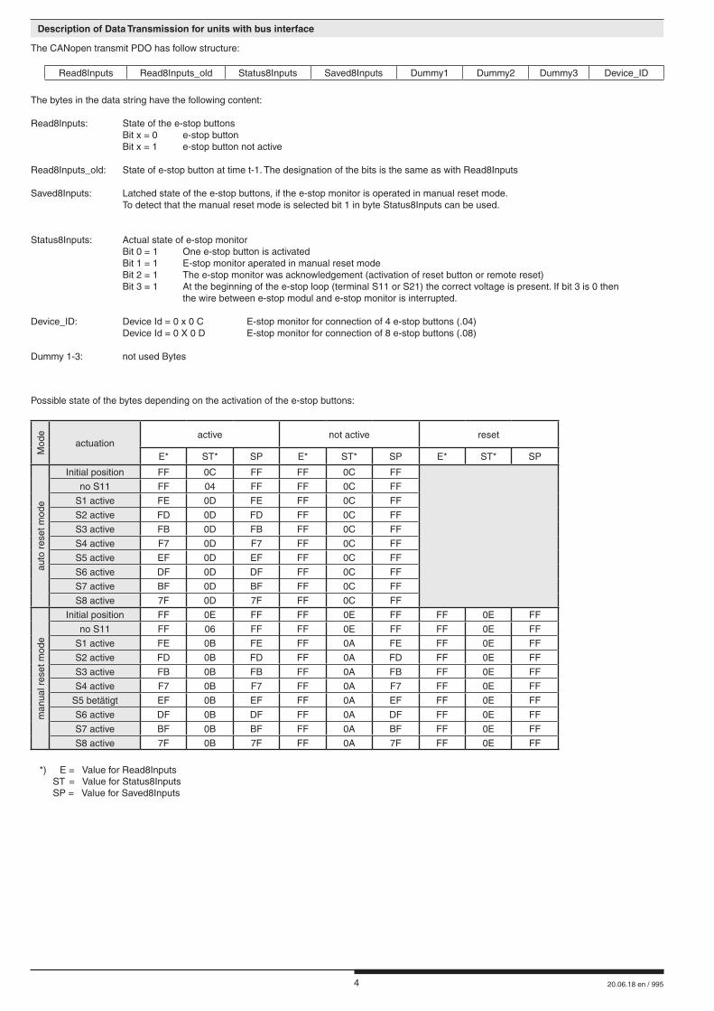
Possible state of the bytes depending on the activation of the e-stop buttons:
Mod
e
actuationactive not active reset
E* ST* SP E* ST* SP E* ST* SP
auto
res
et m
ode
Initial position FF 0C FF FF 0C FF
no S11 FF 04 FF FF 0C FF
S1 active FE 0D FE FF 0C FF
S2 active FD 0D FD FF 0C FF
S3 active FB 0D FB FF 0C FF
S4 active F7 0D F7 FF 0C FF
S5 active EF 0D EF FF 0C FF
S6 active DF 0D DF FF 0C FF
S7 active BF 0D BF FF 0C FF
S8 active 7F 0D 7F FF 0C FF
man
ual r
eset
mod
e
Initial position FF 0E FF FF 0E FF FF 0E FF
no S11 FF 06 FF FF 0E FF FF 0E FF
S1 active FE 0B FE FF 0A FE FF 0E FF
S2 active FD 0B FD FF 0A FD FF 0E FF
S3 active FB 0B FB FF 0A FB FF 0E FF
S4 active F7 0B F7 FF 0A F7 FF 0E FF
S5 betätigt EF 0B EF FF 0A EF FF 0E FF
S6 active DF 0B DF FF 0A DF FF 0E FF
S7 active BF 0B BF FF 0A BF FF 0E FF
S8 active 7F 0B 7F FF 0A 7F FF 0E FF
*) E = Value for Read8Inputs ST = Value for Status8Inputs SP = Value for Saved8Inputs
The CANopen transmit PDO has follow structure:
Read8Inputs Read8Inputs_old Status8Inputs Saved8Inputs Dummy1 Dummy2 Dummy3 Device_ID
The bytes in the data string have the following content:
Read8Inputs: State of the e-stop buttons Bit x = 0 e-stop button Bit x = 1 e-stop button not active
Read8Inputs_old: State of e-stop button at time t-1. The designation of the bits is the same as with Read8Inputs
Saved8Inputs: Latched state of the e-stop buttons, if the e-stop monitor is operated in manual reset mode. To detect that the manual reset mode is selected bit 1 in byte Status8Inputs can be used.
Status8Inputs: Actual state of e-stop monitor Bit 0 = 1 One e-stop button is activated Bit 1 = 1 E-stop monitor aperated in manual reset mode Bit 2 = 1 The e-stop monitor was acknowledgement (activation of reset button or remote reset) Bit 3 = 1 At the beginning of the e-stop loop (terminal S11 or S21) the correct voltage is present. If bit 3 is 0 then the wire between e-stop modul and e-stop monitor is interrupted.
Device_ID: Device Id = 0 x 0 C E-stop monitor for connection of 4 e-stop buttons (.04) Device Id = 0 X 0 D E-stop monitor for connection of 8 e-stop buttons (.08)
Dummy 1-3: not used Bytes
Description of Data Transmission for units with bus interface
5 20.06.18 en / 995
Input
Nominal voltage UN (A1/A2): DC 24 VVoltage range: 0,8 ... 1,1 UN
Control voltage on S11/S12: DC 24 VReset input X1, X2: Voltfree contactBCD interface: Output (O0,O1,O2, O3): Transistor switching +switched /auxiliary voltage: DC 24 VSwitching capacity: 40 mA short circuit proofResidual voltage: typ. 0,6 V
General Data
Operating mode: Continuous operationTemperature range: Operation: - 20 ... + 60 °CStorage: - 40 ... + 70 °CAltitude: < 2.000 m EMCElectrostatic discharge: 8 kV (air) IEC/EN 61 000-4-2Surge proof against wirebound surges, induced byhigh frequency fields: 10 V class 3, f = 150 kHz - 80 MHz IEC/EN 61 000-4-6Fast transients: 2 kV IEC/EN 61 000-4-4Surge voltagesbetweenwires for power supply: 1 kV IEC/EN 61 000-4-5between wire and ground: 2 kV IEC/EN 61 000-4-5Interference suppression: Limit value class A*)
*) The device is designed for the usage under industrial conditions (Class A, EN 55011). When connected to a low voltage public system (Class B, EN 55011) radio interference can be generated. To avoid this, appropriate measures have to be taken.Degree of protectionHousing: IP 40 IEC/EN 60 529Terminals: IP 20 IEC/EN 60 529Housing: Thermoplastic with V0-behaviour to UL subject 94Vibration resistance: Amplitude 0,35 mm IEC/EN 60 068-2-6 frequency 10 ... 55 Hz Climate resistance: 20 / 060 / 04 IEC/EN 60 068-1Terminal designation: EN 50 005Wire connection: 1 x 4 mm2 solid or 1 x 2,5 mm2 stranded ferruled or 2 x 1,5 mm2 stranded ferruled DIN 46 228-1/-2/-3/-4 or 2 x 2,5 mm2 stranded ferruled DIN 46 228-1/-2/-3Wire fixing: Terminal screws M3.5, box terminals with wire protectionMounting: DIN rail IEC/EN 60 715Weight: BH 5922: approx. 255 gBL 5922: approx. 470 g
Dimensions
Width x height x depth:BH 5922: 45 x 86 x 121 mmBL 5922: 90 x 86 x 121 mm
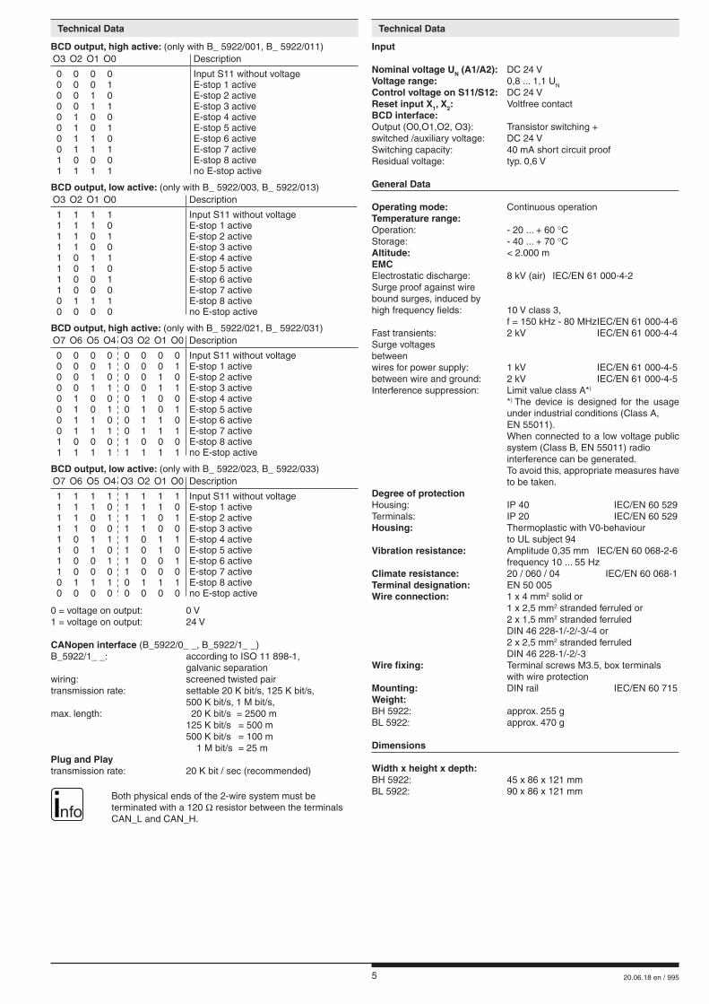
BCD output, high active: (only with B_ 5922/001, B_ 5922/011)O3 O2 O1 O0 Description
0 0 0 0 Input S11 without voltage0 0 0 1 E-stop 1 active0 0 1 0 E-stop 2 active0 0 1 1 E-stop 3 active0 1 0 0 E-stop 4 active0 1 0 1 E-stop 5 active0 1 1 0 E-stop 6 active0 1 1 1 E-stop 7 active1 0 0 0 E-stop 8 active1 1 1 1 no E-stop active
BCD output, low active: (only with B_ 5922/003, B_ 5922/013)O3 O2 O1 O0 Description
1 1 1 1 Input S11 without voltage1 1 1 0 E-stop 1 active1 1 0 1 E-stop 2 active1 1 0 0 E-stop 3 active1 0 1 1 E-stop 4 active1 0 1 0 E-stop 5 active1 0 0 1 E-stop 6 active1 0 0 0 E-stop 7 active0 1 1 1 E-stop 8 active0 0 0 0 no E-stop active
BCD output, high active: (only with B_ 5922/021, B_ 5922/031)O7 O6 O5 O4 O3 O2 O1 O0 Description
0 0 0 0 0 0 0 0 Input S11 without voltage0 0 0 1 0 0 0 1 E-stop 1 active0 0 1 0 0 0 1 0 E-stop 2 active0 0 1 1 0 0 1 1 E-stop 3 active0 1 0 0 0 1 0 0 E-stop 4 active0 1 0 1 0 1 0 1 E-stop 5 active0 1 1 0 0 1 1 0 E-stop 6 active0 1 1 1 0 1 1 1 E-stop 7 active1 0 0 0 1 0 0 0 E-stop 8 active1 1 1 1 1 1 1 1 no E-stop active
BCD output, low active: (only with B_ 5922/023, B_ 5922/033) O7 O6 O5 O4 O3 O2 O1 O0 Description
1 1 1 1 1 1 1 1 Input S11 without voltage1 1 1 0 1 1 1 0 E-stop 1 active1 1 0 1 1 1 0 1 E-stop 2 active1 1 0 0 1 1 0 0 E-stop 3 active1 0 1 1 1 0 1 1 E-stop 4 active1 0 1 0 1 0 1 0 E-stop 5 active1 0 0 1 1 0 0 1 E-stop 6 active1 0 0 0 1 0 0 0 E-stop 7 active0 1 1 1 0 1 1 1 E-stop 8 active0 0 0 0 0 0 0 0 no E-stop active
0 = voltage on output: 0 V1 = voltage on output: 24 V
CANopen interface (B_5922/0_ _, B_5922/1_ _) B_5922/1_ _: according to ISO 11 898-1, galvanic separationwiring: screened twisted pairtransmission rate: settable 20 K bit/s, 125 K bit/s, 500 K bit/s, 1 M bit/s,max. length: 20 K bit/s = 2500 m 125 K bit/s = 500 m 500 K bit/s = 100 m 1 M bit/s = 25 mPlug and Playtransmission rate: 20 K bit / sec (recommended)
nfo Both physical ends of the 2-wire system must be
terminated with a 120 Ω resistor between the terminals CAN_L and CAN_H.
Technical Data Technical Data
6 20.06.18 en / 995
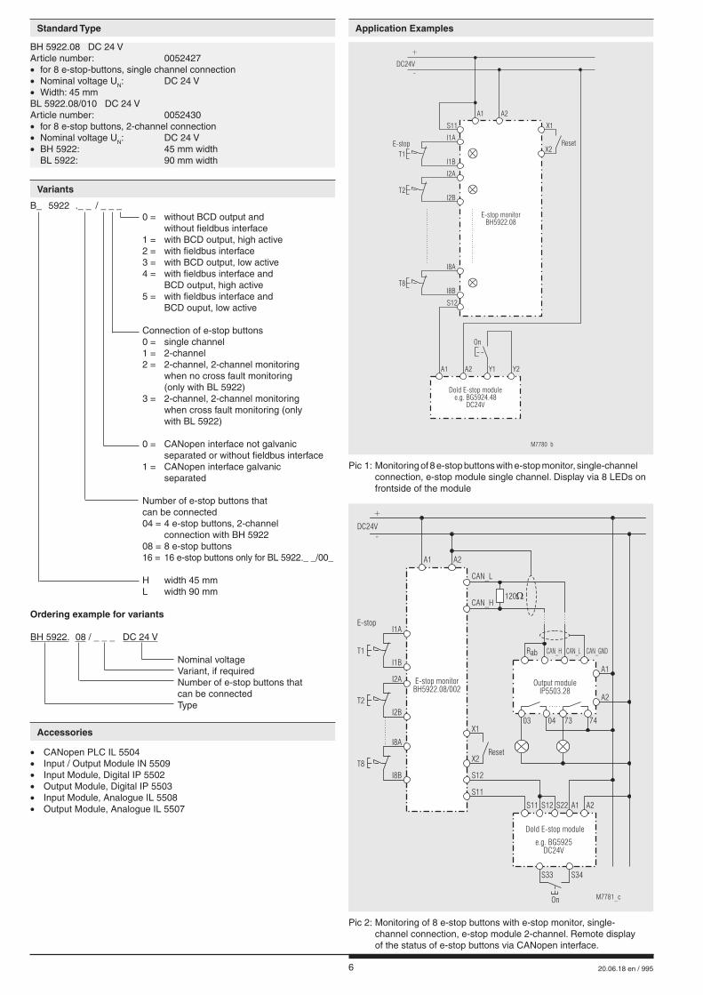
B_ 5922 ._ _ / _ _ _ 0 = without BCD output and without fieldbus interface 1 = with BCD output, high active 2 = with fieldbus interface 3 = with BCD output, low active 4 = with fieldbus interface and BCD output, high active 5 = with fieldbus interface and BCD ouput, low active
Connection of e-stop buttons 0 = single channel 1 = 2-channel 2 = 2-channel, 2-channel monitoring when no cross fault monitoring (only with BL 5922) 3 = 2-channel, 2-channel monitoring when cross fault monitoring (only with BL 5922)
0 = CANopen interface not galvanic separated or without fieldbus interface 1 = CANopen interface galvanic separated
Number of e-stop buttons that can be connected 04 = 4 e-stop buttons, 2-channel connection with BH 5922 08 = 8 e-stop buttons 16 = 16 e-stop buttons only for BL 5922._ _/00_ H width 45 mm L width 90 mm
Ordering example for variants
BH 5922. 08 / _ _ _ DC 24 V Nominal voltage Variant, if required Number of e-stop buttons that can be connected Type
BH 5922.08 DC 24 VArticle number: 0052427 • for 8 e-stop-buttons, single channel connection• Nominal voltage UN: DC 24 V• Width: 45 mmBL 5922.08/010 DC 24 VArticle number: 0052430 • for 8 e-stop buttons, 2-channel connection• Nominal voltage UN: DC 24 V• BH 5922: 45 mm width BL 5922: 90 mm width
Pic 1: Monitoring of 8 e-stop buttons with e-stop monitor, single-channel connection, e-stop module single channel. Display via 8 LEDs on frontside of the module
E-stop
E-stop monitorBH5922.08
On
M7780_b
Dold E-stop modulee.g. BG5924.48
DC24V
T1
T2
T8
Reset
X1
X2
A1
I1A
I2A
I8A
I1B
I2B
I8B
S12
A2 Y1 Y2
A1
S11
A2
DC24V-
+
Pic 2: Monitoring of 8 e-stop buttons with e-stop monitor, single- channel connection, e-stop module 2-channel. Remote display of the status of e-stop buttons via CANopen interface.
A1
M7781_c
A2
E-stop monitorBH5922.08/002
S11
S11
S12
X1
X2Reset
Rab
S12 S22
CAN_H CAN_L
CAN_L
A1
CAN_H120
A2
Output moduleIP5503.28
Dold E-stop module
e.g. BG5925DC24V
I2A
I8A
I8B
I2B
I1B
I1A
T1
T2
T8
03 04 73 74
E-stop
DC24V-
+
A1 A2
S33 S34
On
CAN_GND
• CANopen PLC IL 5504• Input / Output Module IN 5509• Input Module, Digital IP 5502• Output Module, Digital IP 5503• Input Module, Analogue IL 5508• Output Module, Analogue IL 5507
Standard Type Application Examples
Variants
Accessories
7 20.06.18 en / 995
E-stop monitorBH5922.08/001
E-stop monitorBH5922.08/001
Dold-E-stop module
e.g. BG5925DC24V
A1
A1
M7782_b
A2
A2
S11 S12 S22
03
03
02
02
01
01
00
00
BCD
BCD
X1
X1
X2
S11
X2
S12
S12
Rese
t
S11
I2A
I2A
I8A
I8A
I8B
I8B
I2B
I2B
I1B
I1B
I1A
I1A
T1
T9
T2
T10
T8
T16
E-stop
DC24V-
+
A1 A2 S33 S34
On
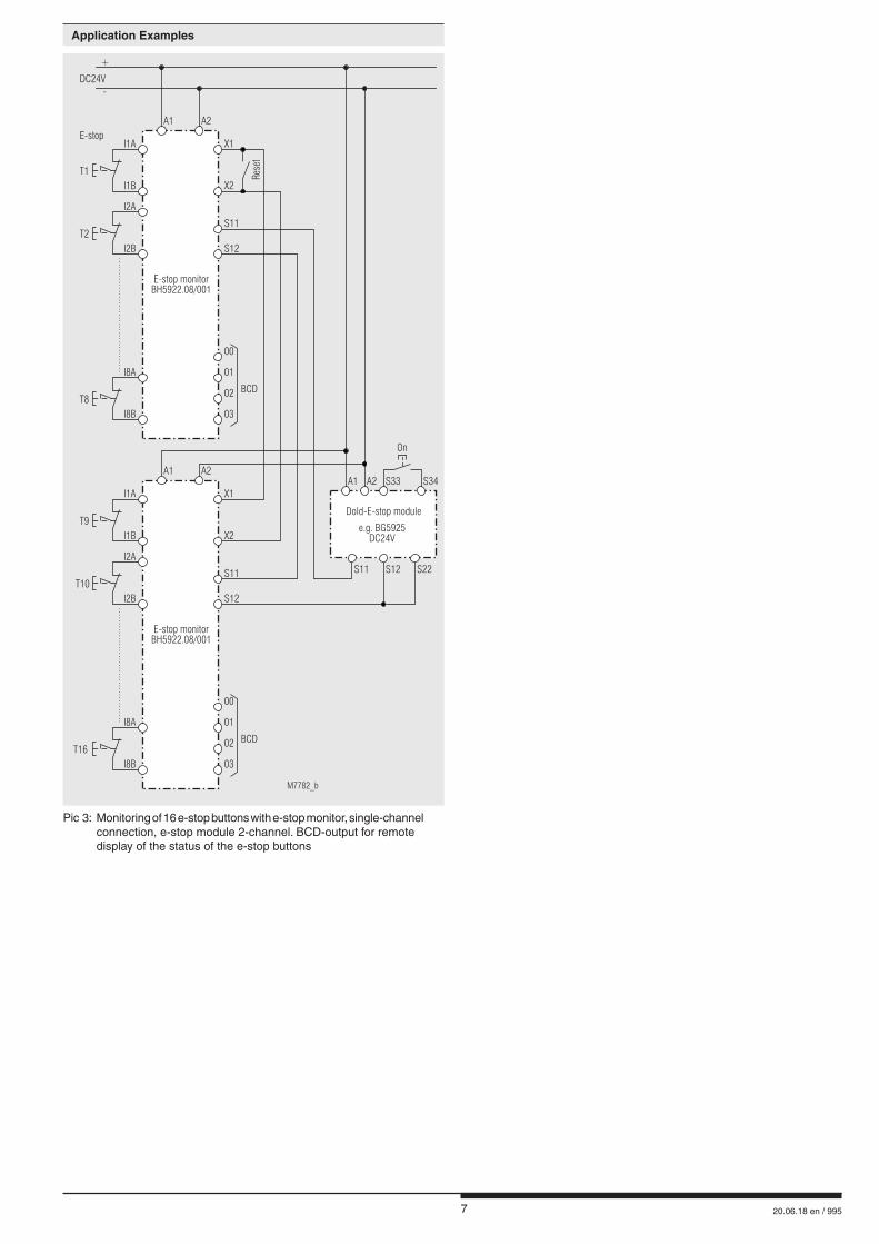
Pic 3: Monitoring of 16 e-stop buttons with e-stop monitor, single-channel connection, e-stop module 2-channel. BCD-output for remote display of the status of the e-stop buttons
Application Examples
8 20.06.18 en / 995
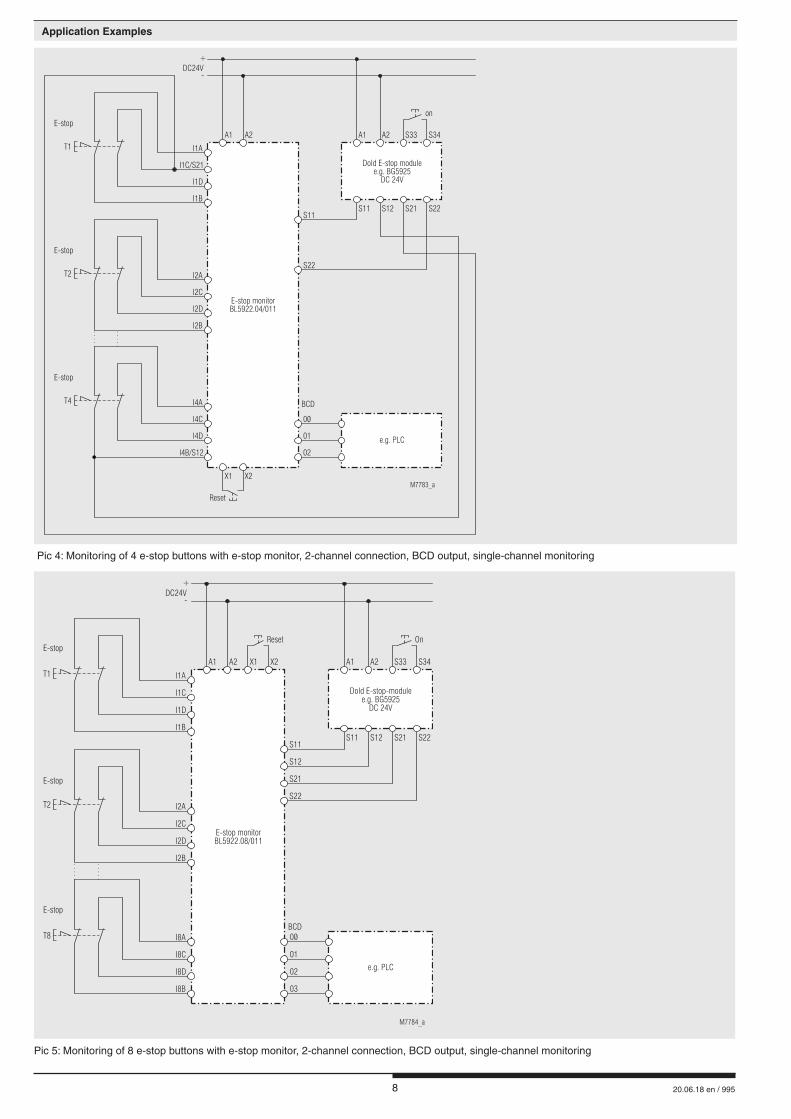
Pic 4: Monitoring of 4 e-stop buttons with e-stop monitor, 2-channel connection, BCD output, single-channel monitoring
on
Reset
A1
e.g. PLC
02
01
00
BCD
M7783_a
A2
E-stop monitorBL5922.04/011
S11S11 S12 S21 S22
A1 A2 S33 S34
S22
Dold E-stop modulee.g. BG5925
DC 24V
T1
T2
T4
E-stop
E-stop
E-stop
I1D
I2D
I4D
I1B
I2B
I4B/S12
X1 X2
I1C/S21
I2C
I4C
I1A
I2A
I4A
DC24V-
+
Pic 5: Monitoring of 8 e-stop buttons with e-stop monitor, 2-channel connection, BCD output, single-channel monitoring
OnReset
A1
e.g. PLC
03
02
01
00BCD
M7784_a
A2 X1 X2
E-stop monitorBL5922.08/011
S11S11 S12 S21 S22
A1 A2 S33 S34
S21
S12
S22
Dold E-stop-modulee.g. BG5925
DC 24V
T1
T2
T8
E-stop
E-stop
E-stop
I1D
I2D
I8D
I1B
I2B
I8B
I1C
I2C
I8C
I1A
I2A
I8A
DC24V-
+
Application Examples
9 20.06.18 en / 995
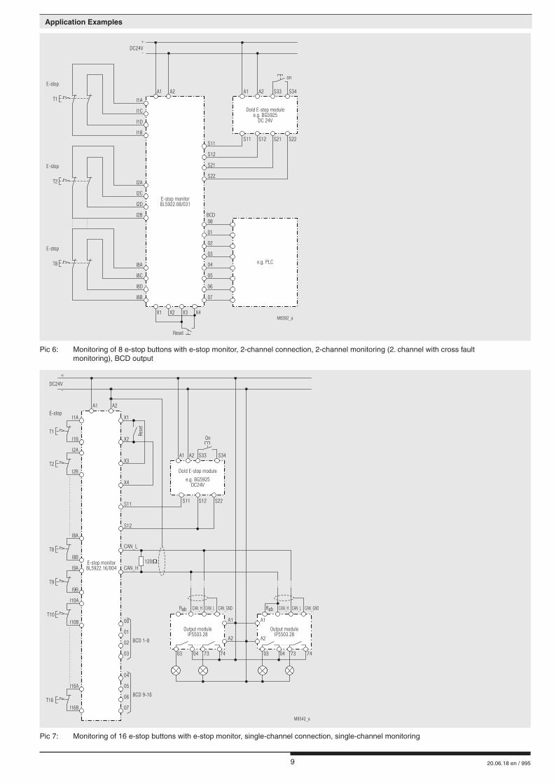
Pic 6: Monitoring of 8 e-stop buttons with e-stop monitor, 2-channel connection, 2-channel monitoring (2. channel with cross fault monitoring), BCD output
on
Reset
A1
e.g. PLC
07
03
06
02
05
01
04
00BCD
M8392_a
A2
E-stop monitorBL5922.08/031
S11S11 S12 S21 S22
A1 A2 S33 S34
S21
S12
S22
Dold E-stop modulee.g. BG5925
DC 24V
T1
T2
T8
E-stop
E-stop
E-stop
I1D
I2D
I8D
I1B
I2B
I8B
X1 X2 X3 X4
I1C
I2C
I8C
I1A
I2A
I8A
DC24V-
+
A1
M8542_a
A2
E-stop monitorBL5922.16/004
S11 S12 S22
03
07
02
06
01
05
00
04
BCD 1-8
BCD 9-16
X1
X2
X3
X4
S11
S12
CAN_L
CAN_H120
Rese
t
Dold E-stop module
e.g. BG5925DC24V
I2A
I8A
I9A
I10A
I16A
I8B
I9B
I10B
I16B
I2B
I1B
I1A
T1
T2
T8
T9
T10
T16
E-stop
DC24V-
+
A1 A2 S33 S34
On
Rab RabCAN_H CAN_HCAN_L CAN_L
A1 A1
A2 A2
Output moduleIP5503.28
03 0304 0473 7374 74
Output moduleIP5503.28
CAN_GND CAN_GND
Pic 7: Monitoring of 16 e-stop buttons with e-stop monitor, single-channel connection, single-channel monitoring
Application Examples
10 20.06.18 en / 995
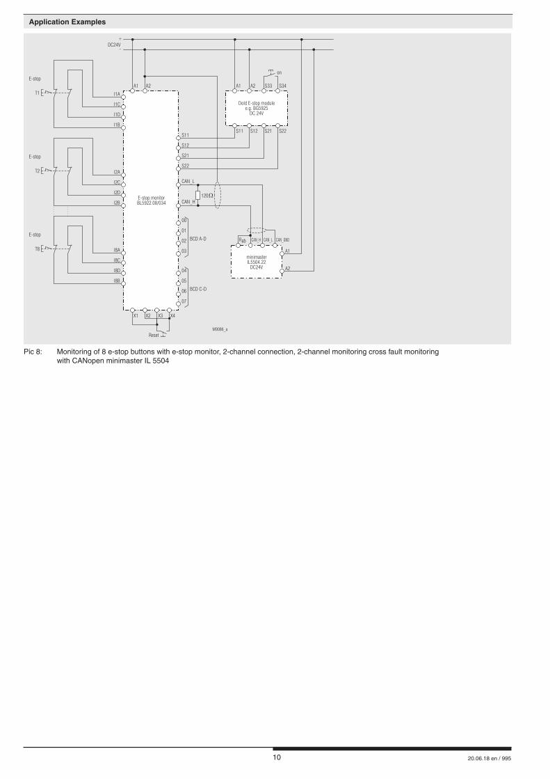
Pic 8: Monitoring of 8 e-stop buttons with e-stop monitor, 2-channel connection, 2-channel monitoring cross fault monitoring with CANopen minimaster IL 5504
Application Examples
on
Reset
A1
M9086_a
A2
S11S11 S12 S21 S22
A1 A2 S33 S34
S21
S12
S22
T1
T2
T8
I1D
I2D
I8D
I1B
I2B
I8B
X1 X2 X3 X4
I1C
I2C
I8C
I1A
I2A
I8A
DC24V-
+
03
07
02
06
01
05
00
04
BCD A-D
BCD C-D
CAN_L
CAN_H120
Rab CAN_H CAN_L CAN_GND
A1
A2
minimasterIL5504.22
DC24V
E-stop
E-stop
E-stop
E-stop monitorBL5922.08/034
Dold E-stop modulee.g. BG5925
DC 24V
11 20.06.18 en / 995
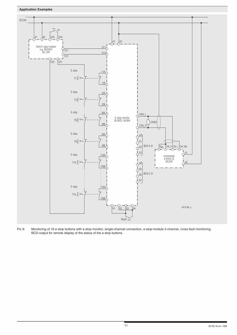
Pic 9: Monitoring of 16 e-stop buttons with e-stop monitor, single-channel connection, e-stop-module 2-channel, cross fault monitoring. BCD-output for remote display of the status of the e-stop buttons.
on
Reset
A1
M10196_a
A2
E-stop monitorBL5922.16/004
S11S11
S12
S22 S21
A1 A2 S33 S34
S12
Dold E-stop modulee.g. BG5925
DC 24V
T1
T8
T10
T2
T9
T16
E-stop
E-stop
E-stop
E-stop
E-stop
E-stop
X1 X2 X3 X4
DC24V-
+
03
07
02
06
01
05
00
04
BCD A-D
BCD C-D
CAN_L
CAN_H120
Rab CAN_H CAN_L CAN_GND
A1
A2
minimasterIL5504.22
DC24V
I10A
I16A
I10B
I16B
I1B
I8B
I2B
I9B
I1A
I8A
I2A
I9A
Application Examples

12 20.06.18 en / 995
E. DOLD & SÖHNE KG • D-78114 Furtwangene-mail: [email protected] • internet: http://www.dold.com
• PO Box 1251 • Telephone (+49) 77 23 / 654-0 • Telefax (+49) 77 23 / 654-356