Embed Size (px)
Citation preview
ABB AB / Jokab Safety Varlabergsvägen 11, SE-434 39 Kungsbacka, Sweden www.abb.com/jokabsafety
Original instructions
LineStrong-series
Emergency Stop Grab Wire Safety Switch
2TLC172248M0201, rev. B 2 www.abb.com/jokabsafety 2013-04-11
Read and understand this document Please read and understand this document before using the products. Please consult your ABB JOKAB SAFETY representative if you have any questions or comments.
WARRANTY
ABB JOKAB SAFETY’s exclusive warranty is that the products are free from defects in materials and workmanship for a period of one year (or other period if specified) from date of sale by ABB JOKAB SAFETY.
ABB JOKAB SAFETY MAKES NO WARRANTY OR REPRESENTATION, EXPRESSED OR IMPLIED, REGARDING NON-INFRINGEMENT, MERCHANTABILITY, OR FITNESS FOR PARTICULAR PURPOSE OF THE PRODUCTS, ANY BUYER OR USER ACKNOWLEDGES THAT THE BUYER OR USER ALONE HAS DETERMINED THAT THE PRODUCTS WILL SUITABLY MEET THE REQUIREMENTS OR THEIR INTENDED USE. ABB JOKAB SAFETY DISCLAIMS ALL OTHER WARRANTIES, EXPRESSED OR IMPLIED.
LIMITATIONS OF LIABILITY
ABB JOKAB SAFETY SHALL NOT BE RESPONSIBLE FOR SPECIAL, INDIRECT, OR CONSEQUENTIAL DAMAGES, LOSS OF PROFITS OR COMMERCIAL LOSS IN ANY WAY CONNECTED WITH THE PRODUCTS, WHETHER SUCH CLAIM IS BASED ON CONTRACT, WARRANTY, NEGLIGENCE, OR STRICT LIABILITY.
In no event shall responsibility of ABB JOKAB SAFETY for any act exceed the individual price of the product on which liability asserted.
IN NO EVENT SHALL ABB JOKAB SAFETY BE RESPONSIBLE FOR WARRANTY, REPAIR, OR OTHER CLAIMS REGARDING THE PRODUCTS UNLESS ABB JOKAB SAFETY’S ANALYSIS CONFIRMS THAT THE PRODUCTS WERE PROPERLY HANDLED, STORED, INSTALLED, AND MAINTAINED AND NOT SUBJECT TO ABUSE, MISUSE, OR INAPPROPRIATE MODIFICATION OR REPAIR.
SUITABILITY FOR USE
ABB JOKAB SAFETY shall not be responsible for conformity with any standards, codes, or regulations that apply to the combination of products in the customer’s application or use of the product. At the customer’s request, ABB JOKAB SAFETY will provide applicable third party certification documents identifying ratings and limitations of use that apply to the products. This information by itself is not sufficient for a complete determination of the suitability of the products in combination with the end product, machine, system, or other application or use.
The following are some examples of applications for which particular attention must be given. This is not intended to be an exhaustive list of all possible uses of the products, nor is it intended to imply that the uses listed may be suitable for the products:
Outdoor use, uses involving potential chemical contamination or electrical interference, or conditions or uses not described in this document.
Nuclear energy control systems, combustion systems, railroad systems, aviation systems, medical equipment, amusement machines, vehicles, and installations subject to separate industry or government regulations.
Systems, machines, and equipment that could present a risk to life or property.
Please know and observe all prohibitions of use applicable to the products.
NEVER USE THE PRODUCTS FOR AN APPLICATION INVOLVING SERIOUS RISK TO LIFE OR PROPERTY WITHOUT ENSURING THAT THE SYSTEM AS A WHOLE HAS BEEN DESIGNED TO ADDRESS THE RISKS, AND THAT THE ABB JOKAB SAFETY PRODUCT IS PROPERLY RATED AND INSTALLED FOR THE INTENDED USE WITHIN THE OVERALL EQUIPMENT OR SYSTEM.
PERFORMANCE DATA
While every effort has been taken to ensure the accuracy of the information contained in this manual ABB JOKAB SAFETY cannot accept responsibility for errors or omissions and reserves the right to make changes and improvements without notice. Performance data given in this document is provided as a guide for the user in determining suitability and does not constitute a warranty. It may represent the result of ABB JOKAB SAFETY’S test conditions, and the users must correlate it to actual application requirements. Actual performance is subject to the ABB JOKAB SAFETY Warranty and Limitations of Liability.
2TLC172248M0201, rev. B 3 www.abb.com/jokabsafety 2013-04-11
Table of Contents 1 Introduction ......................................................................................................................................... 4
Scope ........................................................................................................................................................................ 4
Audience ................................................................................................................................................................... 4
Prerequisites ............................................................................................................................................................. 4
Special notes ............................................................................................................................................................ 4
2 Overview .............................................................................................................................................. 5
General description ................................................................................................................................................... 5
Safety regulations ..................................................................................................................................................... 5
Function description for the variants ......................................................................................................................... 6
3 Connections ...................................................................................................................................... 10
4 Installation and maintenance ........................................................................................................... 11
Installation of the Safety Switch .............................................................................................................................. 11
Installation of the wire ............................................................................................................................................. 12
Tensioner/Gripper ................................................................................................................................................... 13
Maintenance ........................................................................................................................................................... 15
5 Application examples ........................................................................................................................ 16
6 Model overview .................................................................................................................................. 17
Dimensions ............................................................................................................................................................. 17
Accessories ............................................................................................................................................................. 19
7 Technical data ................................................................................................................................... 20
LineStrong1 ............................................................................................................................................................. 20
LineStrong2 series .................................................................................................................................................. 22
LineStrong3 series .................................................................................................................................................. 24
8 EC Declaration of conformity ........................................................................................................... 26
2TLC172248M0201, rev. B 4 www.abb.com/jokabsafety 2013-04-11
1 Introduction Scope The purpose of these instructions is to describe the Emergency Stop Grab Wire Safety Switch system LineStrong-series, and to provide the necessary information required for assembly, installation, checks and adjustments after installation, and maintenance. The instructions also include information necessary to connect LineStrong to a safety circuit.
Audience This document is intended for authorized installation personnel.
Prerequisites It is assumed that the reader of this document has knowledge of the following:
• Basic knowledge of ABB Jokab Safety products.
• Knowledge of machine safety.
Special notes Pay attention to the following special notes in the document:
Warning! Danger of severe personal injury! An instruction or procedure which, if not carried out correctly, may result in injury to the technician or other personnel.
Caution! Danger of damage to the equipment! An instruction or procedure which, if not carried out correctly, may damage the equipment.
NB: Notes are used to provide important or explanatory information.
2TLC172248M0201, rev. B 5 www.abb.com/jokabsafety 2013-04-11
2 Overview General description All ABB Jokab Safety Emergency strop grab wire safety switches conform to European Standard EN ISO 13850 and IEC 60947-5-5. They have a positive mechanical linkage between the switch contacts and the wire as per IEC 60947-5-1. The emergency stop switches are brought into the operational condition by pre-tensioning the wire by use of a tensioner / gripper device which clamps the wire and then hooks to the switch eyebolts. Correct tension can be observed by viewing the tension indicator on the switch housing. Once tensioned the switch contact blocks can be set to the operational condition (safety contacts closed, auxiliary contacts open) by pressing a blue reset button on the switch cover.
All of the grab wire safety switches have wire-breakage monitoring. On pulling or breakage (tension loss) of the wire, the safety contacts are positively opened and the auxiliary contacts are closed. The switches are mechanically latched and can then only be returned to the operational condition by a pressing the reset button as required by EN ISO 13850.
Safety regulations
Warning! Carefully read through this entire manual before using the device.
The devices shall be installed by a trained electrician following the Safety regulations, standards and the Machine directive.
Failure to comply with instructions, operation that is not in accordance with the use prescribed in these instructions, improper installation or handling of the device can affect the safety of people and the plant.
For installation and prescribed use of the product, the special notes in the instructions must be carefully observed and the technical standards relevant to the application must be considered.
In case of failure to comply with the instructions or standards, especially when tampering with and/or modifying the product, any liability is excluded.
2TLC172248M0201, rev. B 6 www.abb.com/jokabsafety 2013-04-11
Function description for the variants
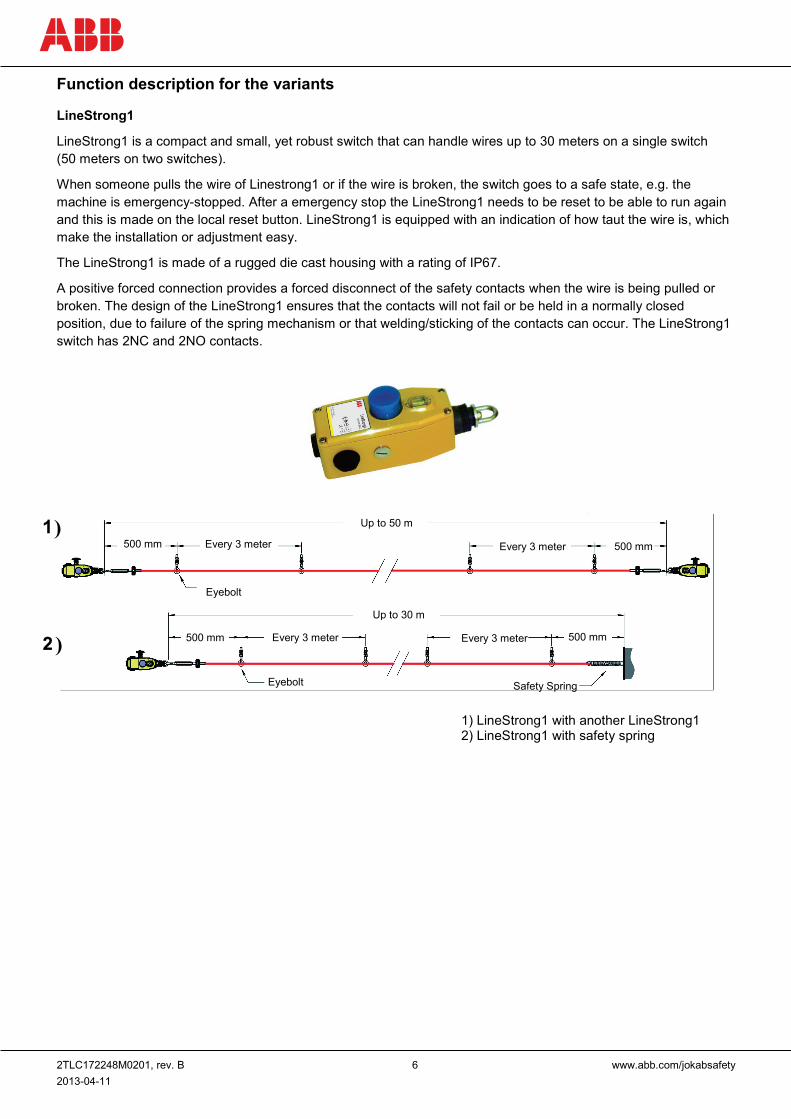
LineStrong1
LineStrong1 is a compact and small, yet robust switch that can handle wires up to 30 meters on a single switch (50 meters on two switches).
When someone pulls the wire of Linestrong1 or if the wire is broken, the switch goes to a safe state, e.g. the machine is emergency-stopped. After a emergency stop the LineStrong1 needs to be reset to be able to run again and this is made on the local reset button. LineStrong1 is equipped with an indication of how taut the wire is, which make the installation or adjustment easy.
The LineStrong1 is made of a rugged die cast housing with a rating of IP67.
A positive forced connection provides a forced disconnect of the safety contacts when the wire is being pulled or broken. The design of the LineStrong1 ensures that the contacts will not fail or be held in a normally closed position, due to failure of the spring mechanism or that welding/sticking of the contacts can occur. The LineStrong1 switch has 2NC and 2NO contacts.
Up to 50 m
500 mm Every 3 meter Every 3 meter 500 mm
Up to 30 m
Eyebolt
500 mm 500 mm Every 3 meter Every 3 meter
Eyebolt Safety Spring
1) LineStrong1 with another LineStrong1 2) LineStrong1 with safety spring
)
)
2TLC172248M0201, rev. B 7 www.abb.com/jokabsafety 2013-04-11
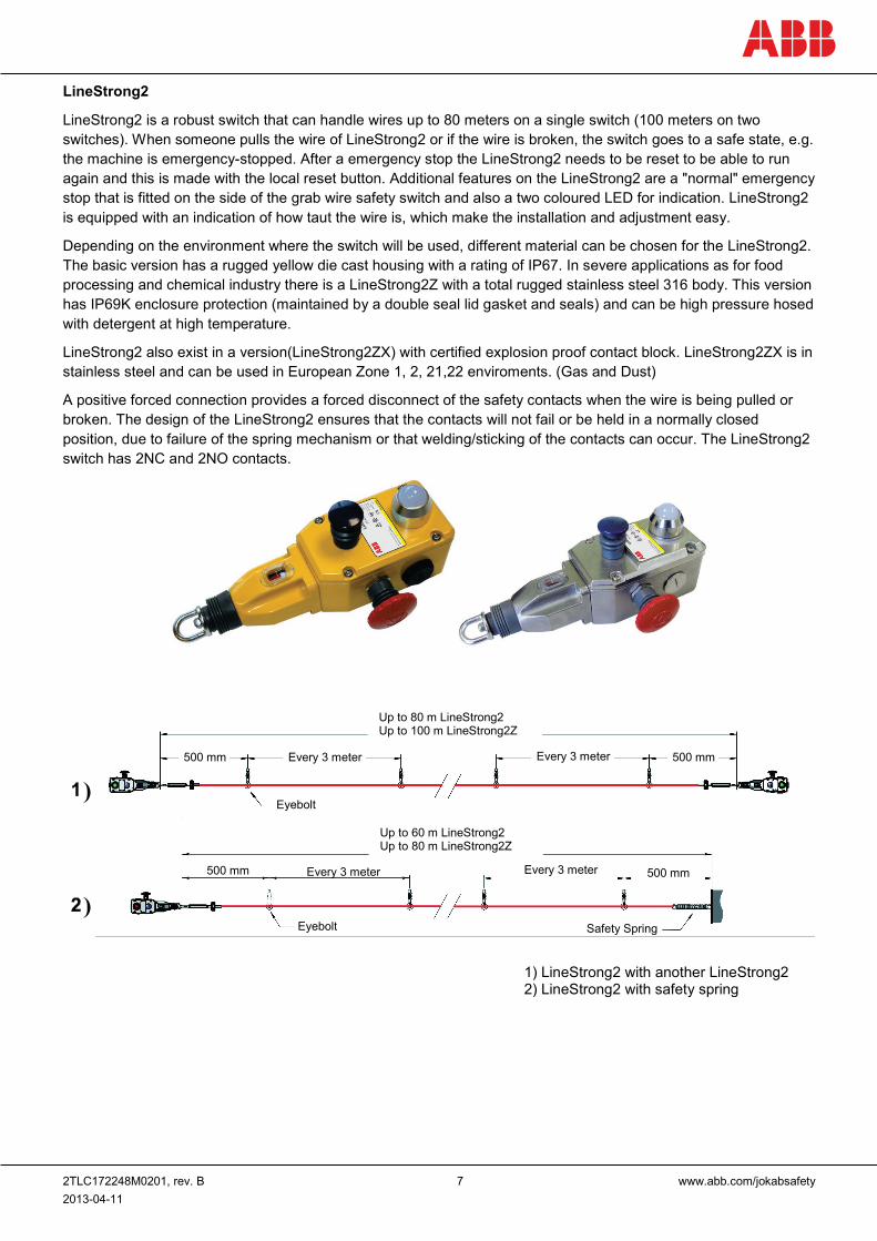
LineStrong2
LineStrong2 is a robust switch that can handle wires up to 80 meters on a single switch (100 meters on two switches). When someone pulls the wire of LineStrong2 or if the wire is broken, the switch goes to a safe state, e.g. the machine is emergency-stopped. After a emergency stop the LineStrong2 needs to be reset to be able to run again and this is made with the local reset button. Additional features on the LineStrong2 are a "normal" emergency stop that is fitted on the side of the grab wire safety switch and also a two coloured LED for indication. LineStrong2 is equipped with an indication of how taut the wire is, which make the installation and adjustment easy.
Depending on the environment where the switch will be used, different material can be chosen for the LineStrong2. The basic version has a rugged yellow die cast housing with a rating of IP67. In severe applications as for food processing and chemical industry there is a LineStrong2Z with a total rugged stainless steel 316 body. This version has IP69K enclosure protection (maintained by a double seal lid gasket and seals) and can be high pressure hosed with detergent at high temperature.
LineStrong2 also exist in a version(LineStrong2ZX) with certified explosion proof contact block. LineStrong2ZX is in stainless steel and can be used in European Zone 1, 2, 21,22 enviroments. (Gas and Dust)
A positive forced connection provides a forced disconnect of the safety contacts when the wire is being pulled or broken. The design of the LineStrong2 ensures that the contacts will not fail or be held in a normally closed position, due to failure of the spring mechanism or that welding/sticking of the contacts can occur. The LineStrong2 switch has 2NC and 2NO contacts.
Up to 80 m LineStrong2 Up to 100 m LineStrong2Z
500 mm 500 mm
500 mm 500 mm
Every 3 meter Every 3 meter
Every 3 meter Every 3 meter
Eyebolt
Eyebolt Safety Spring
1) LineStrong2 with another LineStrong2 2) LineStrong2 with safety spring
Up to 60 m LineStrong2 Up to 80 m LineStrong2Z
)
)
2TLC172248M0201, rev. B 8 www.abb.com/jokabsafety 2013-04-11
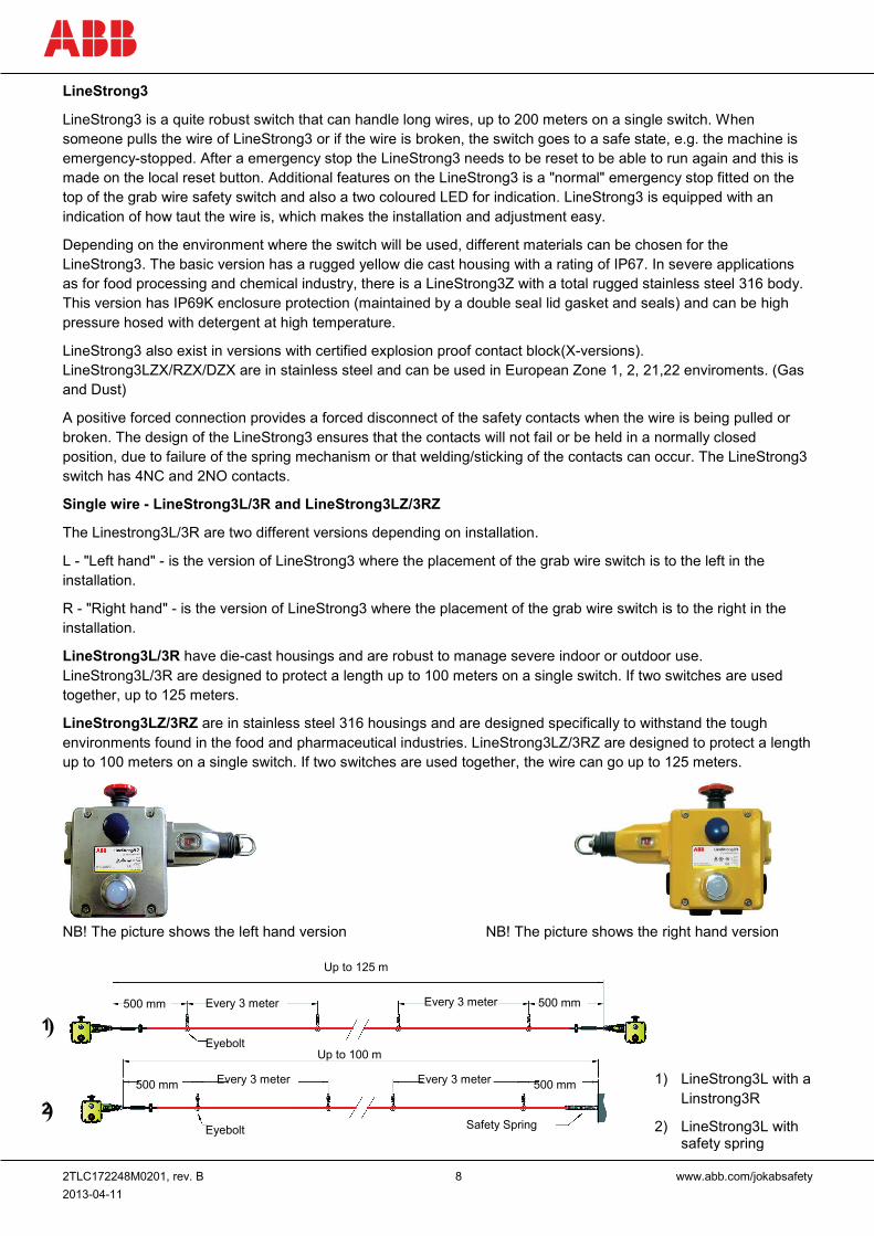
LineStrong3
LineStrong3 is a quite robust switch that can handle long wires, up to 200 meters on a single switch. When someone pulls the wire of LineStrong3 or if the wire is broken, the switch goes to a safe state, e.g. the machine is emergency-stopped. After a emergency stop the LineStrong3 needs to be reset to be able to run again and this is made on the local reset button. Additional features on the LineStrong3 is a "normal" emergency stop fitted on the top of the grab wire safety switch and also a two coloured LED for indication. LineStrong3 is equipped with an indication of how taut the wire is, which makes the installation and adjustment easy.
Depending on the environment where the switch will be used, different materials can be chosen for the LineStrong3. The basic version has a rugged yellow die cast housing with a rating of IP67. In severe applications as for food processing and chemical industry, there is a LineStrong3Z with a total rugged stainless steel 316 body. This version has IP69K enclosure protection (maintained by a double seal lid gasket and seals) and can be high pressure hosed with detergent at high temperature.
LineStrong3 also exist in versions with certified explosion proof contact block(X-versions). LineStrong3LZX/RZX/DZX are in stainless steel and can be used in European Zone 1, 2, 21,22 enviroments. (Gas and Dust)
A positive forced connection provides a forced disconnect of the safety contacts when the wire is being pulled or broken. The design of the LineStrong3 ensures that the contacts will not fail or be held in a normally closed position, due to failure of the spring mechanism or that welding/sticking of the contacts can occur. The LineStrong3 switch has 4NC and 2NO contacts.
Single wire - LineStrong3L/3R and LineStrong3LZ/3RZ
The Linestrong3L/3R are two different versions depending on installation.
L - "Left hand" - is the version of LineStrong3 where the placement of the grab wire switch is to the left in the installation.
R - "Right hand" - is the version of LineStrong3 where the placement of the grab wire switch is to the right in the installation.
LineStrong3L/3R have die-cast housings and are robust to manage severe indoor or outdoor use. LineStrong3L/3R are designed to protect a length up to 100 meters on a single switch. If two switches are used together, up to 125 meters.
LineStrong3LZ/3RZ are in stainless steel 316 housings and are designed specifically to withstand the tough environments found in the food and pharmaceutical industries. LineStrong3LZ/3RZ are designed to protect a length up to 100 meters on a single switch. If two switches are used together, the wire can go up to 125 meters.
NB! The picture shows the left hand version NB! The picture shows the right hand version
1) LineStrong3L with a Linstrong3R
2) LineStrong3L with safety spring
500 mm
500 mm
500 mm
500 mm
Every 3 meter
Every 3 meter
Every 3 meter
Every 3 meter
Up to 125 m
Up to 100 m Eyebolt
Eyebolt Safety Spring
)
)
2TLC172248M0201, rev. B 9 www.abb.com/jokabsafety 2013-04-11
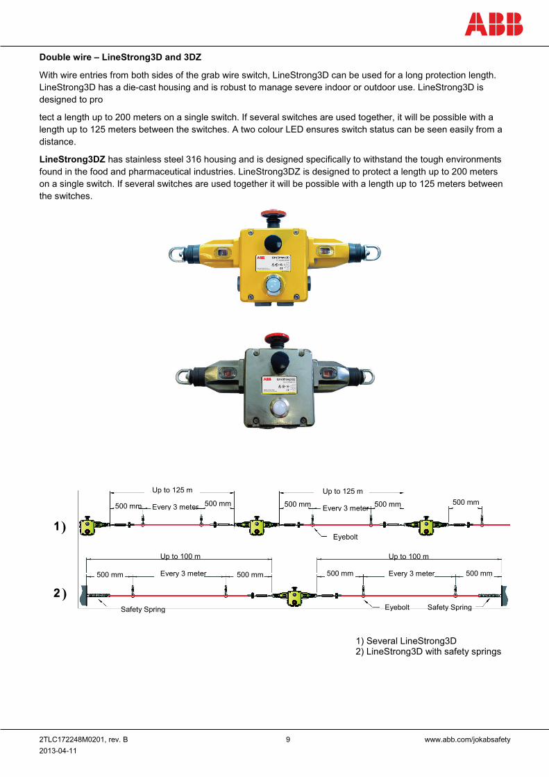
Double wire – LineStrong3D and 3DZ
With wire entries from both sides of the grab wire switch, LineStrong3D can be used for a long protection length. LineStrong3D has a die-cast housing and is robust to manage severe indoor or outdoor use. LineStrong3D is designed to pro
tect a length up to 200 meters on a single switch. If several switches are used together, it will be possible with a length up to 125 meters between the switches. A two colour LED ensures switch status can be seen easily from a distance.
LineStrong3DZ has stainless steel 316 housing and is designed specifically to withstand the tough environments found in the food and pharmaceutical industries. LineStrong3DZ is designed to protect a length up to 200 meters on a single switch. If several switches are used together it will be possible with a length up to 125 meters between the switches.
Up to 125 m Every 3 meter
Up to 125 m Every 3 meter
Up to 100 m Every 3 meter
Up to 100 m Every 3 meter
500 mm 500 mm 500 mm 500 mm 500 mm
500 mm 500 mm 500 mm 500 mm
Eyebolt
Eyebolt Safety Spring Safety Spring
1) Several LineStrong3D 2) LineStrong3D with safety springs
)
)
2TLC172248M0201, rev. B 10 www.abb.com/jokabsafety 2013-04-11
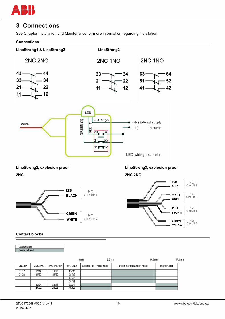
3 Connections See Chapter Installation and Maintenance for more information regarding installation.
Connections
LineStrong1 & LineStrong2 LineStrong3
LineStrong2, explosion proof LineStrong3, explosion proof
2NC 2NC 2NO
Contact blocks
LED wiring example
2TLC172248M0201, rev. B 11 www.abb.com/jokabsafety 2013-04-11
4 Installation and maintenance Installation of the Safety Switch
1. The installation of all Emergency Stop Grab Wire Safety Switch systems must be in accordance with a risk assessment for the individual application. Installation must only be carried out by competent personnel and in accordance with these instructions.
2. According to ISO 13850, corner pulleys may only be mounted such that a complete length of the wire can
be observed.
3. Wire support eyebolts must be fitted at 2.5 m. min. to 3m. max.intervals along all wire lengths between switches. The wire must be supported no more than 500mm from the switch eyebolt or Safety Spring (if used). It is important that this first 500mm is not used as part of the active protection coverage.
4. M5 mounting bolts must be used to fix the switches. Tightening torque for mounting bolts to ensure reliable
fixing is 4 Nm. Tightening torque for the lid screws,conduit entry plugs and cable glands must be 1.5 Nm to ensure IP seal. Only use the correct size gland for the conduit entry and cable outside diameter.
5. Tensioning of wire is achieved by use of ABB tensioner / gripper assemblies.
Upon installation, tension to mid position is indicated by the green arrows in the viewing window of each switch. Check operation of all switches and the control circuits by pulling the wire at various locations along the active protection area and resetting each switch by pressing the blue Reset button. Ensure each time that the switches latch off, and require manual resetting by pressing the Reset button. Increase the system tension further, if required, depending upon the checks along the active length of coverage. If safety switch is fitted with a Mushroom type E-Stop button (Red) then test and reset this part of the switch to ensure correct function of the safety control circuits. Typical operational conditions for successful operation of system are less than 75N pulling force and less than 150mm deflection of rope between eyebolt supports.
6. Recommended wire span options and fittings - (subject to an individual risk assessment for the installation)
See Function description for correct wire span for each variant.
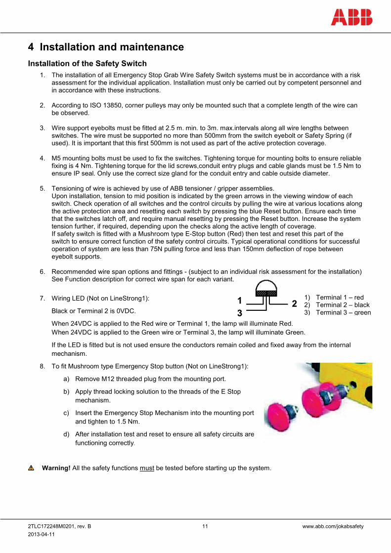
7. Wiring LED (Not on LineStrong1):
Black or Terminal 2 is 0VDC.
When 24VDC is applied to the Red wire or Terminal 1, the lamp will illuminate Red. When 24VDC is applied to the Green wire or Terminal 3, the lamp will illuminate Green.
If the LED is fitted but is not used ensure the conductors remain coiled and fixed away from the internal mechanism.
8. To fit Mushroom type Emergency Stop button (Not on LineStrong1):
a) Remove M12 threaded plug from the mounting port.
b) Apply thread locking solution to the threads of the E Stop mechanism.
c) Insert the Emergency Stop Mechanism into the mounting port and tighten to 1.5 Nm.
d) After installation test and reset to ensure all safety circuits are functioning correctly.
Warning! All the safety functions must be tested before starting up the system.
1) Terminal 1 – red 2) Terminal 2 – black 3) Terminal 3 – green
2TLC172248M0201, rev. B 12 www.abb.com/jokabsafety 2013-04-11
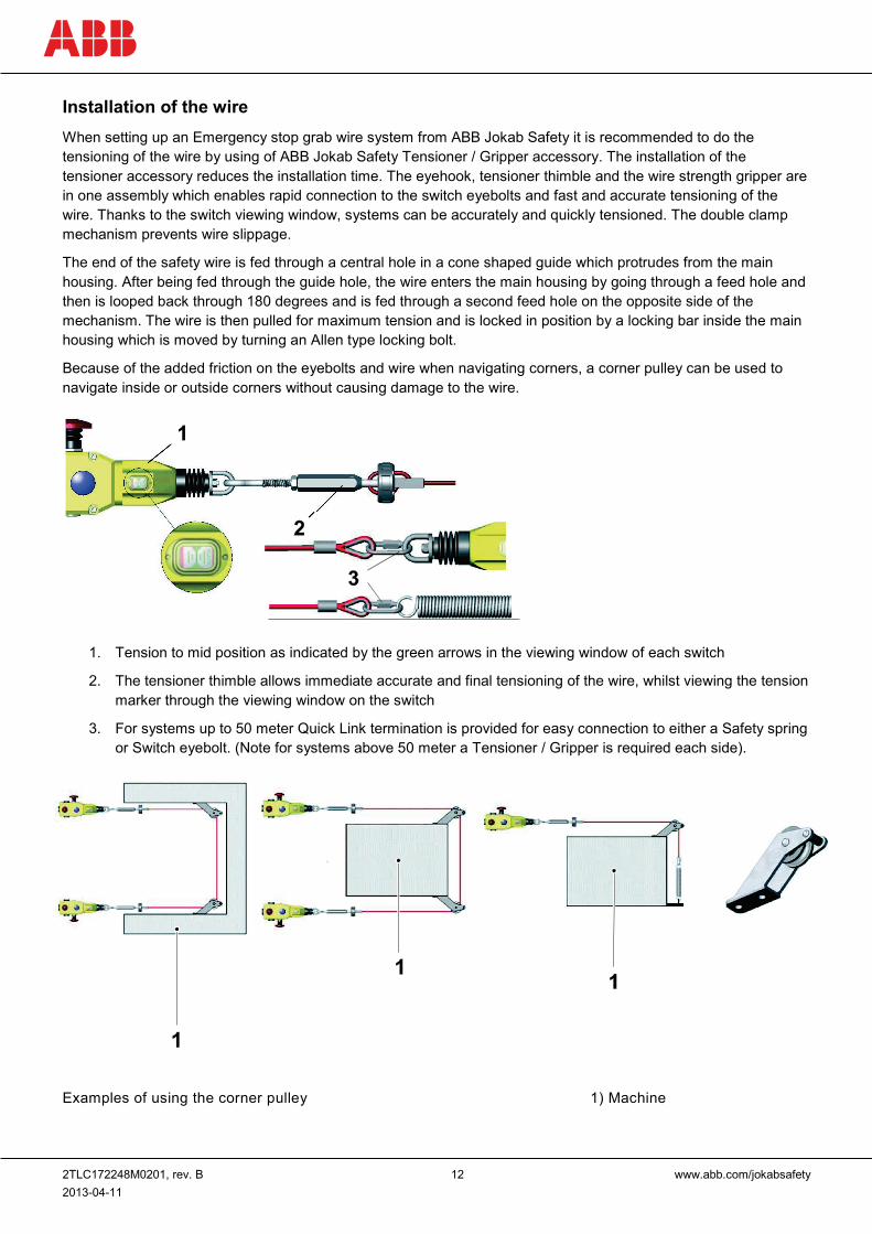
Installation of the wire When setting up an Emergency stop grab wire system from ABB Jokab Safety it is recommended to do the tensioning of the wire by using of ABB Jokab Safety Tensioner / Gripper accessory. The installation of the tensioner accessory reduces the installation time. The eyehook, tensioner thimble and the wire strength gripper are in one assembly which enables rapid connection to the switch eyebolts and fast and accurate tensioning of the wire. Thanks to the switch viewing window, systems can be accurately and quickly tensioned. The double clamp mechanism prevents wire slippage.
The end of the safety wire is fed through a central hole in a cone shaped guide which protrudes from the main housing. After being fed through the guide hole, the wire enters the main housing by going through a feed hole and then is looped back through 180 degrees and is fed through a second feed hole on the opposite side of the mechanism. The wire is then pulled for maximum tension and is locked in position by a locking bar inside the main housing which is moved by turning an Allen type locking bolt.
Because of the added friction on the eyebolts and wire when navigating corners, a corner pulley can be used to navigate inside or outside corners without causing damage to the wire.
1. Tension to mid position as indicated by the green arrows in the viewing window of each switch
2. The tensioner thimble allows immediate accurate and final tensioning of the wire, whilst viewing the tension marker through the viewing window on the switch
3. For systems up to 50 meter Quick Link termination is provided for easy connection to either a Safety spring or Switch eyebolt. (Note for systems above 50 meter a Tensioner / Gripper is required each side).
Examples of using the corner pulley 1) Machine
Inside corners
Outside corners
Outside corners
2TLC172248M0201, rev. B 13 www.abb.com/jokabsafety 2013-04-11
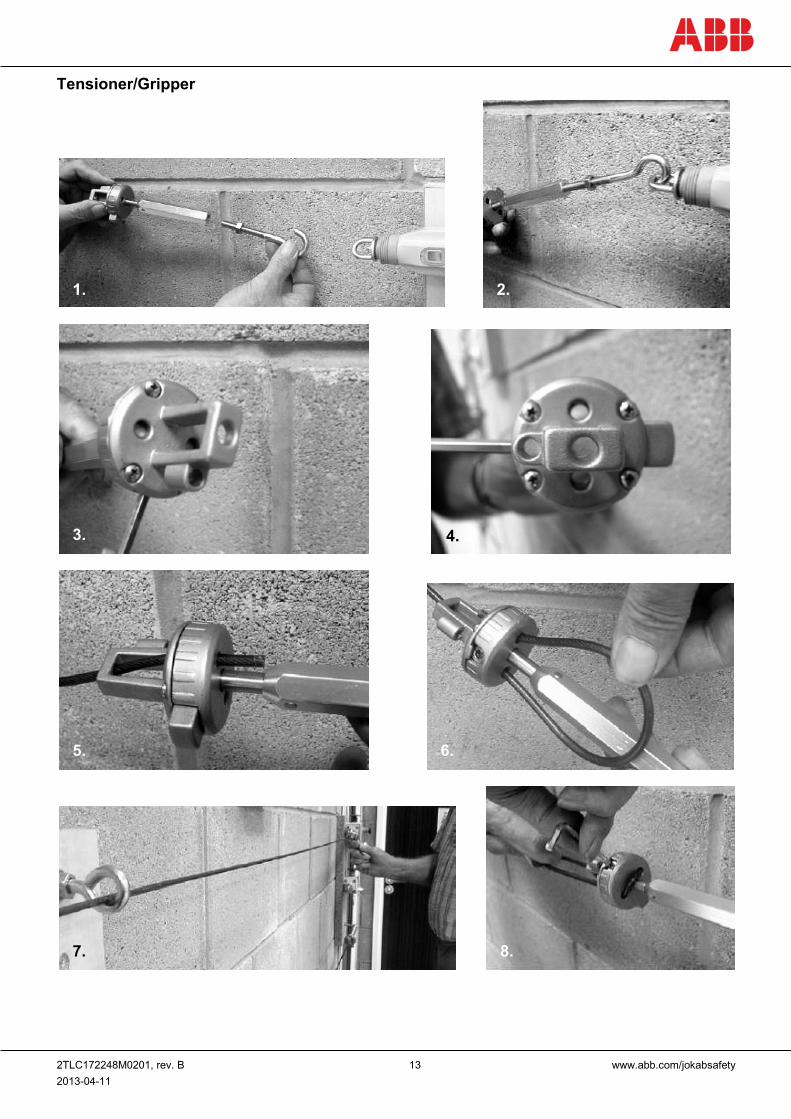
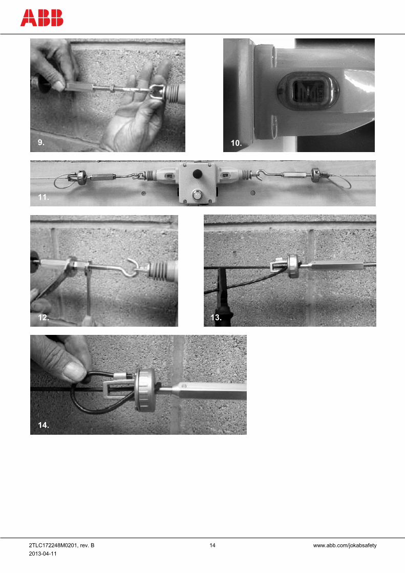
Tensioner/Gripper
1. 2.
3. 4.
5. 6.
7. 8.
2TLC172248M0201, rev. B 14 www.abb.com/jokabsafety 2013-04-11
9. 10.
11.
12. 13.
14.
2TLC172248M0201, rev. B 15 www.abb.com/jokabsafety 2013-04-11
Maintenance Every week: Check correct operation of system at locations along all coverage length and also the switch latching mechanism. Check for nominal tension setting, re-tension wire if necessary.
Every 6 months: Isolate power and remove cover. Check screw terminal tightness and check for signs of moisture ingress.
Warning! The safety functions and the mechanics shall be tested regularly, at least once every year, to confirm that all the safety functions are working properly.
Warning! In case of breakdown or damage to the product, contact the nearest ABB Jokab Safety Service Office or reseller. Do not try to repair the product yourself since it may accidentally cause permanent damage to the product, impairing the safety of the device which in turn could lead to serious injury to personnel.
Caution! ABB Jokab Safety will not accept responsibility for failure of the switch functions if the installation and maintenance requirements shown in this sheet are not implemented. These requirements form part of the product warranty.
2TLC172248M0201, rev. B 16 www.abb.com/jokabsafety 2013-04-11
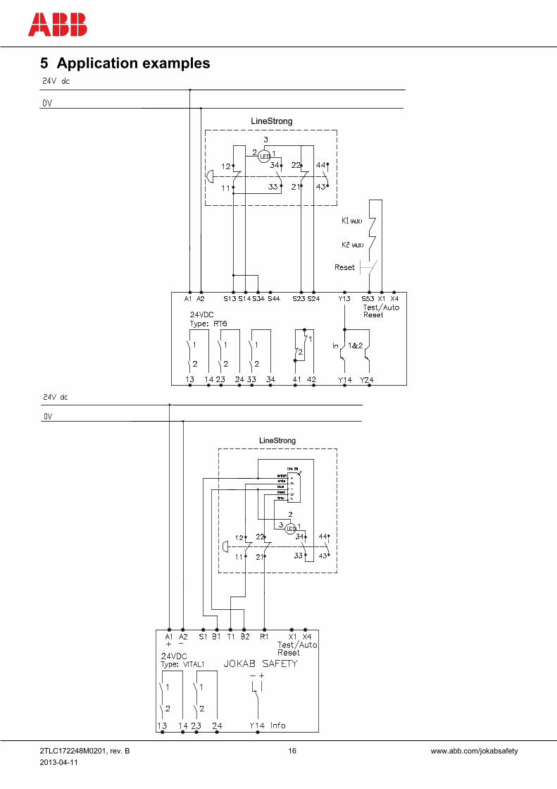
5 Application examples
2TLC172248M0201, rev. B 17 www.abb.com/jokabsafety 2013-04-11
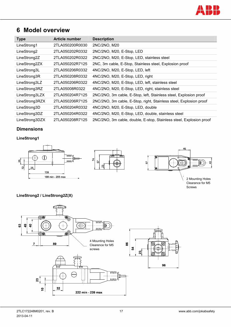
6 Model overview Type Article number Description LineStrong1 2TLA050200R0030 2NC/2NO, M20 LineStrong2 2TLA050202R0332 2NC/2NO, M20, E-Stop, LED LineStrong2Z 2TLA050202R0322 2NC/2NO, M20, E-Stop, LED, stainless steel LineStrong2ZX 2TLA050202R7125 2NC, 3m cable, E-Stop, Stainless steel, Explosion proof LineStrong3L 2TLA050206R0332 4NC/2NO, M20, E-Stop, LED, left LineStrong3R 2TLA050208R0332 4NC/2NO, M20, E-Stop, LED, right LineStrong3LZ 2TLA050206R0322 4NC/2NO, M20, E-Stop, LED, left, stainless steel LineStrong3RZ 2TLA05008R0322 4NC/2NO, M20, E-Stop, LED, right, stainless steel LineStrong3LZX 2TLA050204R7125 2NC/2NO, 3m cable, E-Stop, left, Stainless steel, Explosion proof LineStrong3RZX 2TLA050206R7125 2NC/2NO, 3m cable, E-Stop, right, Stainless steel, Explosion proof LineStrong3D 2TLA050204R0332 4NC/2NO, M20, E-Stop, LED, double LineStrong3DZ 2TLA050204R0322 4NC/2NO, M20, E-Stop, LED, double, stainless steel LineStrong3DZX 2TLA050208R7125 2NC/2NO, 3m cable, double, E-stop, Stainless steel, Explosion proof
Dimensions
LineStrong1
LineStrong2 / LineStrong2Z(X)
4 Mounting Holes Clearence for M5 screws
2 Mounting Holes Clearance for M5 Screws
2TLC172248M0201, rev. B 18 www.abb.com/jokabsafety 2013-04-11
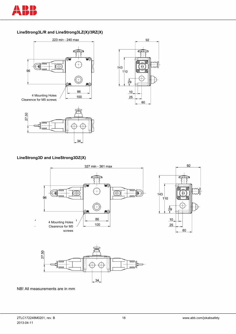
LineStrong3L/R and LineStrong3LZ(X)/3RZ(X)
LineStrong3D and LineStrong3DZ(X)
NB! All measurements are in mm
4 Mounting Holes Clearence for M5
screws
4 Mounting Holes Clearence for M5 screws
2TLC172248M0201, rev. B 19 www.abb.com/jokabsafety 2013-04-11
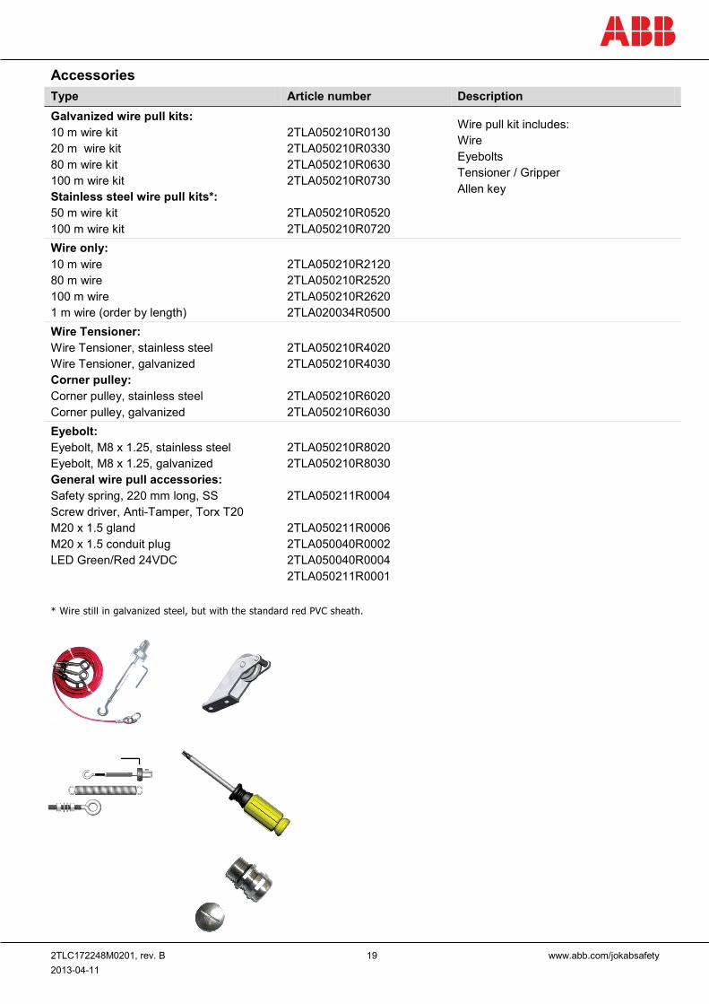
Accessories Type Article number Description Galvanized wire pull kits: 10 m wire kit 20 m wire kit 80 m wire kit 100 m wire kit Stainless steel wire pull kits*: 50 m wire kit 100 m wire kit
2TLA050210R0130 2TLA050210R0330 2TLA050210R0630 2TLA050210R0730 2TLA050210R0520 2TLA050210R0720
Wire pull kit includes: Wire Eyebolts Tensioner / Gripper Allen key
Wire only: 10 m wire 80 m wire 100 m wire 1 m wire (order by length)
2TLA050210R2120 2TLA050210R2520 2TLA050210R2620 2TLA020034R0500
Wire Tensioner: Wire Tensioner, stainless steel Wire Tensioner, galvanized Corner pulley: Corner pulley, stainless steel Corner pulley, galvanized
2TLA050210R4020 2TLA050210R4030 2TLA050210R6020 2TLA050210R6030
Eyebolt: Eyebolt, M8 x 1.25, stainless steel Eyebolt, M8 x 1.25, galvanized General wire pull accessories: Safety spring, 220 mm long, SS Screw driver, Anti-Tamper, Torx T20 M20 x 1.5 gland M20 x 1.5 conduit plug LED Green/Red 24VDC
2TLA050210R8020 2TLA050210R8030 2TLA050211R0004 2TLA050211R0006 2TLA050040R0002 2TLA050040R0004 2TLA050211R0001
* Wire still in galvanized steel, but with the standard red PVC sheath.
2TLC172248M0201, rev. B 20 www.abb.com/jokabsafety 2013-04-11
7 Technical data LineStrong1 Manufacturer Address ABB AB / JOKAB SAFETY
Varlabergsvägen 11 SE-434 39 Kungsbacka Sweden
Electrical characteristics Contact type IEC/EN60947-5-1 double break Typ Zb Contact material Silver Termination Clamp up to 2.5 mm2 conductors Utilisation category AC15 A300 3A 240VAC 3A/120VAC 6A/24VDC 2.5A inductive Thermal current (lth) 10 A Rated insulation/withstand voltages 500VAC / 2500VAC Short circuit overload protection Fuse externally 10 A (FF) General Wire span Up to 50 m Wire tension devise ABB Jokab Safety Wire Tensioner Wire type PVC sheath steel wire 4.0 mm outside diameter Torque settings Mounting M5 4.0Nm
Lid T20 Torx M4 1.5Nm Terminals 1.0Nm
Tension force (typical mid setting) 130 N Tension operating force (wire pulled) < 125N < 300 mm deflection Vibration resistance 10-500 Hz 0.35 mm Shock resistance 15 g 11 ms Conduit entries 3 x M20 x 1.5 Enclosure classification IP67 Ambient temperature -25°C to +80°C Material Die cast painted yellow Mounting position Any Mounting bolts 4 x M5
Weight (approx.) 0.675 kg
2TLC172248M0201, rev. B 21 www.abb.com/jokabsafety 2013-04-11
Safety-related characteristic data and Conformity Conformity European Machinery Directive 2006/42/EC
EN ISO 12100:2010, EN ISO 13850:2008, EN 60204-1:2006+A1:2009 EN 60947-1:2007+A1:2011, EN 60947-5-1:2004+A1:2009, EN 60947-5-5:1997+A1:2005
EN ISO13849-1 Up to PL e, Cat. 4 depending upon system architecture EN 62061 Up to SIL3 depending upon system architecture Safety data Mechanical reliability B10d PFHD Proof test interval (life) MTTFd
1.5 x 10⁶ operations at 100mA load <1.0x10⁻⁷ 21 years 214 years (8 cycles per hour/24 hours per day/365 days)
Certifications TÜV, cULus Information with regard to UL 508 Use 12AWG copper conductors only
Electrical Rating: A300 48W5 Type 1 Enclosure Max. Switching Current / Volt / Amp: 120V 6A (720VA break) PF 0.38, 240V 3A (720VA break) PF 0.38
2TLC172248M0201, rev. B 22 www.abb.com/jokabsafety 2013-04-11
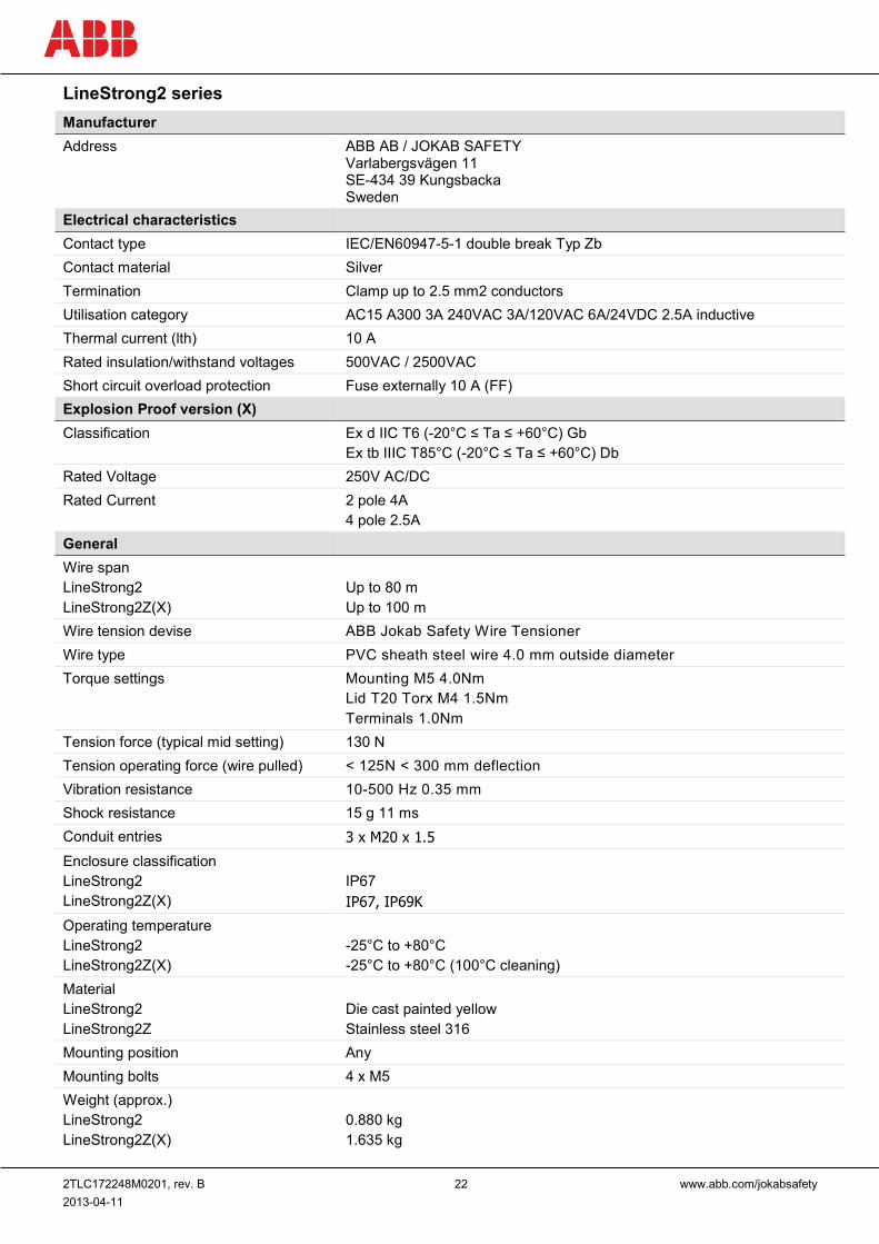
LineStrong2 series Manufacturer Address ABB AB / JOKAB SAFETY
Varlabergsvägen 11 SE-434 39 Kungsbacka Sweden
Electrical characteristics Contact type IEC/EN60947-5-1 double break Typ Zb Contact material Silver Termination Clamp up to 2.5 mm2 conductors Utilisation category AC15 A300 3A 240VAC 3A/120VAC 6A/24VDC 2.5A inductive Thermal current (lth) 10 A Rated insulation/withstand voltages 500VAC / 2500VAC Short circuit overload protection Fuse externally 10 A (FF) Explosion Proof version (X) Classification Ex d IIC T6 (-20°C ≤ Ta ≤ +60°C) Gb
Ex tb IIIC T85°C (-20°C ≤ Ta ≤ +60°C) Db Rated Voltage 250V AC/DC Rated Current 2 pole 4A
4 pole 2.5A General Wire span LineStrong2 LineStrong2Z(X)
Up to 80 m Up to 100 m
Wire tension devise ABB Jokab Safety Wire Tensioner Wire type PVC sheath steel wire 4.0 mm outside diameter Torque settings Mounting M5 4.0Nm
Lid T20 Torx M4 1.5Nm Terminals 1.0Nm
Tension force (typical mid setting) 130 N Tension operating force (wire pulled) < 125N < 300 mm deflection Vibration resistance 10-500 Hz 0.35 mm Shock resistance 15 g 11 ms Conduit entries 3 x M20 x 1.5 Enclosure classification LineStrong2 LineStrong2Z(X)
IP67 IP67, IP69K
Operating temperature LineStrong2 LineStrong2Z(X)
-25°C to +80°C -25°C to +80°C (100°C cleaning)
Material LineStrong2 LineStrong2Z
Die cast painted yellow Stainless steel 316
Mounting position Any Mounting bolts 4 x M5 Weight (approx.) LineStrong2 LineStrong2Z(X)
0.880 kg 1.635 kg
2TLC172248M0201, rev. B 23 www.abb.com/jokabsafety 2013-04-11
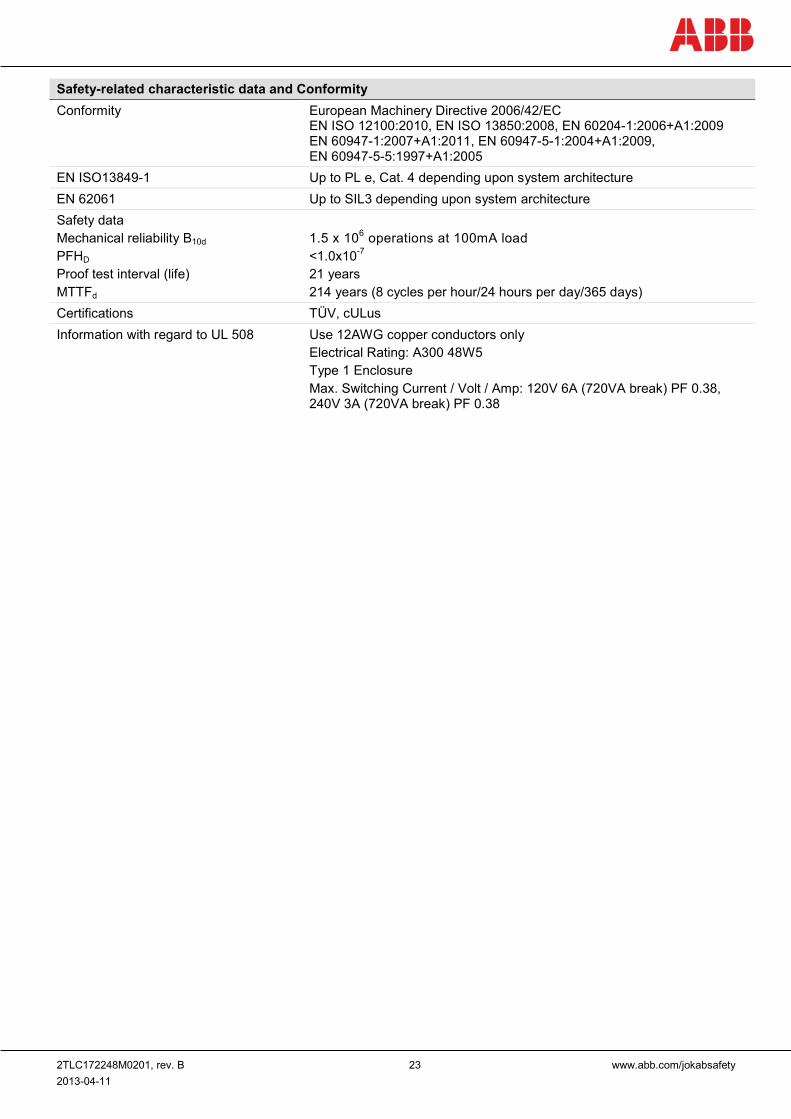
Safety-related characteristic data and Conformity Conformity European Machinery Directive 2006/42/EC
EN ISO 12100:2010, EN ISO 13850:2008, EN 60204-1:2006+A1:2009 EN 60947-1:2007+A1:2011, EN 60947-5-1:2004+A1:2009, EN 60947-5-5:1997+A1:2005
EN ISO13849-1 Up to PL e, Cat. 4 depending upon system architecture EN 62061 Up to SIL3 depending upon system architecture Safety data Mechanical reliability B10d PFHD Proof test interval (life) MTTFd
1.5 x 10⁶ operations at 100mA load <1.0x10⁻⁷ 21 years 214 years (8 cycles per hour/24 hours per day/365 days)
Certifications TÜV, cULus Information with regard to UL 508 Use 12AWG copper conductors only
Electrical Rating: A300 48W5 Type 1 Enclosure Max. Switching Current / Volt / Amp: 120V 6A (720VA break) PF 0.38, 240V 3A (720VA break) PF 0.38
2TLC172248M0201, rev. B 24 www.abb.com/jokabsafety 2013-04-11
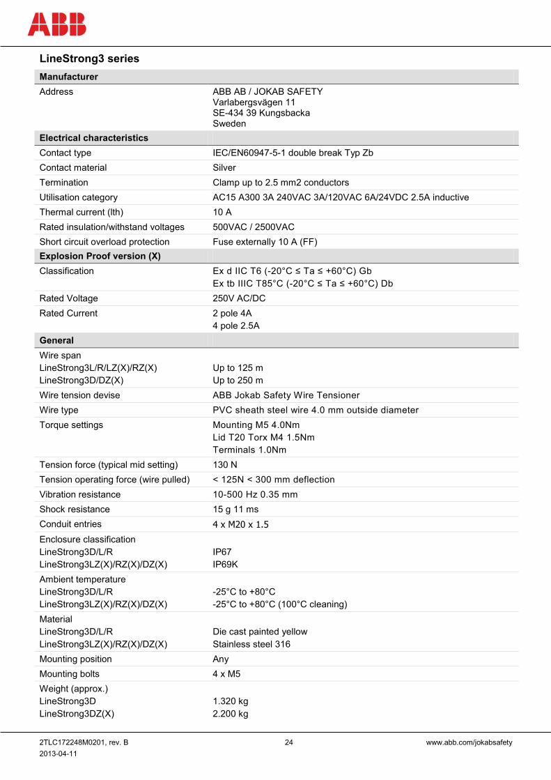
LineStrong3 series Manufacturer Address ABB AB / JOKAB SAFETY
Varlabergsvägen 11 SE-434 39 Kungsbacka Sweden
Electrical characteristics Contact type IEC/EN60947-5-1 double break Typ Zb Contact material Silver Termination Clamp up to 2.5 mm2 conductors Utilisation category AC15 A300 3A 240VAC 3A/120VAC 6A/24VDC 2.5A inductive Thermal current (lth) 10 A Rated insulation/withstand voltages 500VAC / 2500VAC Short circuit overload protection Fuse externally 10 A (FF) Explosion Proof version (X) Classification Ex d IIC T6 (-20°C ≤ Ta ≤ +60°C) Gb
Ex tb IIIC T85°C (-20°C ≤ Ta ≤ +60°C) Db Rated Voltage 250V AC/DC Rated Current 2 pole 4A
4 pole 2.5A General Wire span LineStrong3L/R/LZ(X)/RZ(X) LineStrong3D/DZ(X)
Up to 125 m Up to 250 m
Wire tension devise ABB Jokab Safety Wire Tensioner Wire type PVC sheath steel wire 4.0 mm outside diameter Torque settings Mounting M5 4.0Nm
Lid T20 Torx M4 1.5Nm Terminals 1.0Nm
Tension force (typical mid setting) 130 N Tension operating force (wire pulled) < 125N < 300 mm deflection Vibration resistance 10-500 Hz 0.35 mm Shock resistance 15 g 11 ms Conduit entries 4 x M20 x 1.5 Enclosure classification LineStrong3D/L/R LineStrong3LZ(X)/RZ(X)/DZ(X)
IP67 IP69K
Ambient temperature LineStrong3D/L/R LineStrong3LZ(X)/RZ(X)/DZ(X)
-25°C to +80°C -25°C to +80°C (100°C cleaning)
Material LineStrong3D/L/R LineStrong3LZ(X)/RZ(X)/DZ(X)
Die cast painted yellow Stainless steel 316
Mounting position Any Mounting bolts 4 x M5 Weight (approx.) LineStrong3D LineStrong3DZ(X)
1.320 kg 2.200 kg
2TLC172248M0201, rev. B 25 www.abb.com/jokabsafety 2013-04-11
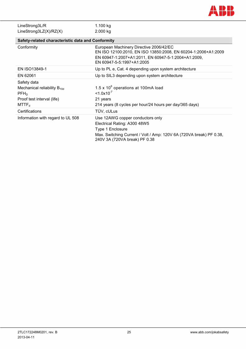
LineStrong3L/R LineStrong3LZ(X)/RZ(X)
1.100 kg 2.000 kg
Safety-related characteristic data and Conformity Conformity European Machinery Directive 2006/42/EC
EN ISO 12100:2010, EN ISO 13850:2008, EN 60204-1:2006+A1:2009 EN 60947-1:2007+A1:2011, EN 60947-5-1:2004+A1:2009, EN 60947-5-5:1997+A1:2005
EN ISO13849-1 Up to PL e, Cat. 4 depending upon system architecture EN 62061 Up to SIL3 depending upon system architecture Safety data Mechanical reliability B10d PFHD Proof test interval (life) MTTFd
1.5 x 10⁶ operations at 100mA load <1.0x10⁻⁷ 21 years 214 years (8 cycles per hour/24 hours per day/365 days)
Certifications TÜV, cULus Information with regard to UL 508 Use 12AWG copper conductors only
Electrical Rating: A300 48W5 Type 1 Enclosure Max. Switching Current / Volt / Amp: 120V 6A (720VA break) PF 0.38, 240V 3A (720VA break) PF 0.38
2TLC172248M0201, rev. B 26 www.abb.com/jokabsafety 2013-04-11
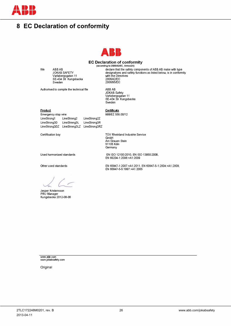
8 EC Declaration of conformity
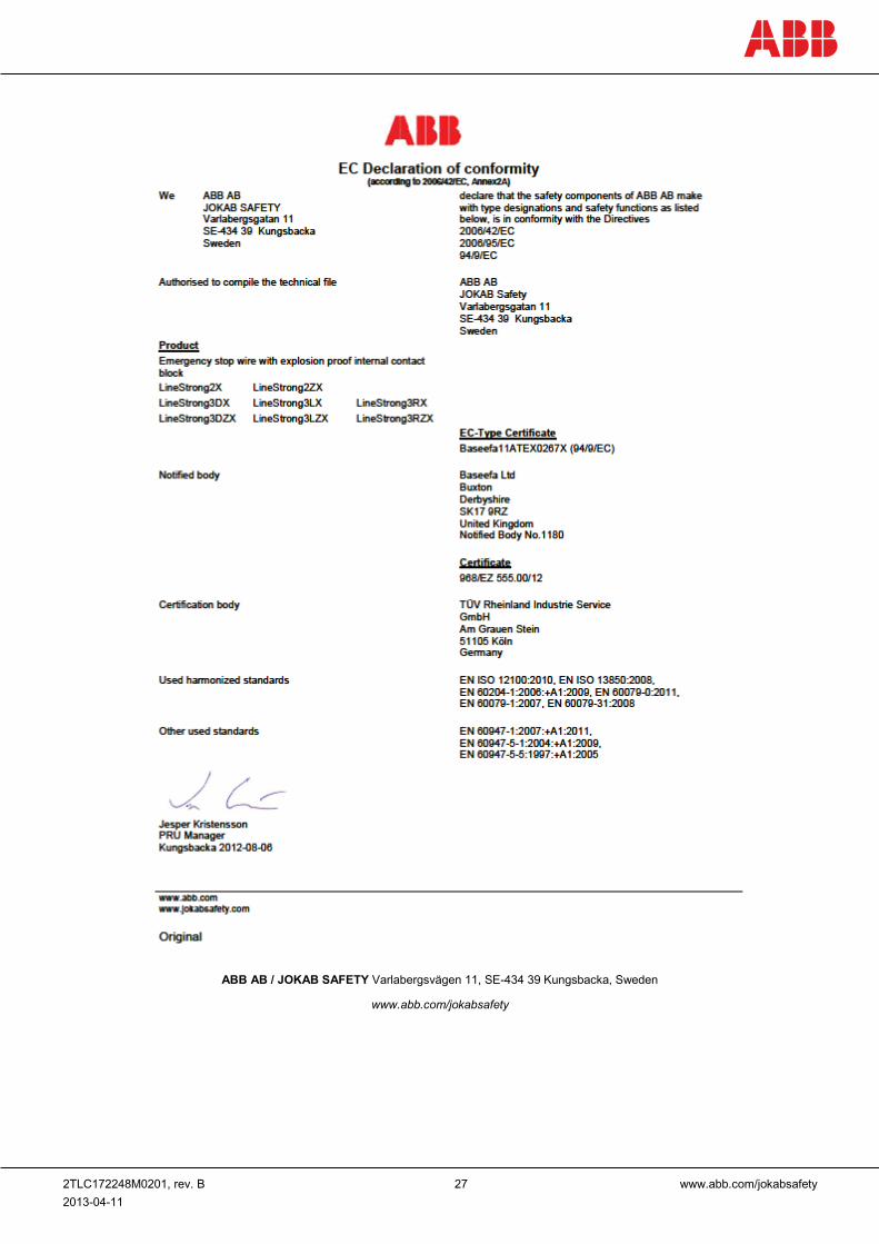
2TLC172248M0201, rev. B 27 www.abb.com/jokabsafety 2013-04-11
ABB AB / JOKAB SAFETY Varlabergsvägen 11, SE-434 39 Kungsbacka, Sweden
www.abb.com/jokabsafety