Embed Size (px)
Citation preview

Prepared for Fire Service, Law Enforcement, Emergency Medical, and ProfessionalTowing Personnel by American Honda Motor Co., Inc.
Emergency Response GuideHonda Fuel Cell Vehicle


Contents
Key Components ................................................................................................................... 2
Vehicle Description ................................................................................................................ 3
Vehicle Type, Size, and Materials .............................................................................. 3
Identifying the FCX Clarity ......................................................................................... 3
Fuel Cell Stack ............................................................................................................ 3
Hydrogen Tank ............................................................................................................ 4
High-Voltage Electric Motors ...................................................................................... 4
Power Drive Unit ......................................................................................................... 4
High-Voltage Battery ................................................................................................... 5
High-Voltage Cables ................................................................................................... 5
12-Volt Battery ............................................................................................................ 5
Occupant Protection Equipment .................................................................................. 6
Built-In Safety Features ......................................................................................................... 7
Crash Detection System .............................................................................................. 7
Hydrogen Tank Safety Valves ...................................................................................... 7
Hydrogen Detectors ..................................................................................................... 8
Potential Hazards .................................................................................................................. 9
Flammable Fluid .......................................................................................................... 9
Hydrogen Properties and Potential Hazards ................................................................ 9
Electric Shock Potential ............................................................................................. 10
High-Voltage Battery Contents ................................................................................... 11
Emergency Procedures ....................................................................................................... 12
Incidents Involving Fire .............................................................................................. 12
Submerged or Partly Submerged Vehicle .................................................................. 12
Shutting Down the High-Voltage, Hydrogen & Airbag Systems ................................. 13
Preferred Method................................................................................................ 13
Alternate Method ................................................................................................ 14
Extricating Occupants ................................................................................................ 16
Emergency Towing ..................................................................................................... 16
1

Key Components
2
HydrogenTank
Hydrogen Supply &Humidifier Systems
Fuel CellContactor
High-VoltageBattery
Fuel CellStack
High-VoltageCables
ACCompressor
Drive Motor/Gearbox
UnderhoodFuse Box
12-VoltBattery
Power DriveUnit (PDU)
Air PumpUnit
DC-DCConverterElectric
Heater
Battery VoltageControl Unit
AC CompressorFuel Cell
Stack
Fuel CellContactor
Hydrogen Supply &Humidifier Systems
High-VoltageBattery
Drive Motor/Gearbox
High-VoltageCables
HydrogenTank
12-VoltBattery
UnderhoodFuse Box
Power Drive Unit(PDU)
Air PumpUnit
ElectricHeater
DC-DCConverter
Battery VoltageControl Unit

3
Vehicle Description
The fuel cell stack is well protected in the lower center of the vehicle,shown here with the underbody covers removed.
Fuel Cell Stack
Vehicle Type, Size, and MaterialsThe Honda FCX Clarity is a 4-door, 4-passenger
sedan that uses fuel cells to convert hydrogen and
oxygen into electrical power. The chassis and most
components are made of steel and aluminum. Some
parts are made of plastic.
Fuel Cell StackThe FCX Clarity’s main power source is a fuel cell
stack housed in a metal box in the lower center of
the vehicle. The stack contains layers of individual
fuel cells that combine hydrogen from an onboard
tank with oxygen brought into the vehicle from air
intakes to produce electricity. The only by-products
of this process are heat and water. Some of the
water is used by the humidifier, and excess water is
vented through the exhaust pipe.
Identifying the FCX ClarityThe Clarity can be identified by the logo containing
the words “FCX and “Clarity” located on the lower
part of both rear passenger doors, and to the left of
the license plate on the rear of the vehicle.

4
Vehicle Description
The hydrogen tank is securely strapped to the FCX Clarity’s frame.
Removing the underbody covers that protect components from dirtand damage reveals the drive motor, located between the frontwheels.
Hydrogen TankThe hydrogen used to generate electricity is
compressed to 5,000 psi and stored in a strong,
refillable tank located behind the rear seats. The
tank is made of nonflammable materials, and has
passed the same rigid impact tests for tanks in cars
fueled by compressed natural gas (CNG). Tank
capacity is 171 liters.
High-Voltage Electric MotorsElectricity generated by the fuel cell stack powers
the drive motor, an air pump motor, and an air
conditioning motor—all located under the hood.
Other high-voltage components include a fuel cell
contactor, forward of the fuel cell stack; a battery
voltage control unit, under the driver’s seat; a DC-
DC converter; a power drive unit; and an electric
heater. (See page 2 for component locations.)
The Power Drive Unit (PDU) is located under other components andcan be reached only by their removal.
Power Drive UnitThe power drive unit (PDU) controls the high-
voltage electric motor power. While the PDU
contains high-voltage components, it is located out
of sight and reach, under other components.

High-Voltage Battery Location
12 Volt Battery
The distinctive orange color makes it easy to identify the location ofhigh-voltage cables, shown here with the underbody coversremoved.
High-Voltage BatteryA lithium-ion battery stores power generated by the
fuel cells and regenerated by the drive motor. It
provides extra current when needed, such as during
acceleration. The battery is housed under the rear
seat and just forward of the hydrogen tank. Its
voltage is nominally 288 volts.
Vehicle Description
High-Voltage CablesElectricity from the fuel cell stack and the high-
voltage battery is delivered to the motors through a
number of cables. Most are located inside or behind
enclosed high-voltage components. Those located
underneath the vehicle are protected by the
underbody covers. Any that might be visible under
the hood can be easily identified by distinctive
orange protective covers.
5
12-Volt BatteryA conventional 12-volt battery is located under the
hood on the driver’s side. This battery powers the
lights, the audio system, and other standard
electrical components. It is also used to start the
drive system.

Vehicle Description
Occupant Protection EquipmentThe FCX Clarity has lap/shoulder belts in all
seating positions, dual front airbags, side airbags in
front, and side curtain airbags. The front seats are
equipped with pyrotechnically activated seat belt
pretensioners. As with conventional automobiles, it
takes about 3 minutes for the airbags and
pretensioners to be disabled after the ignition switch
is turned off or the 12-volt negative battery cable is
cut.
6

The FCX Clarity is designed with a number of built-
in features to protect users, bystanders and
emergency responders.
Crash Detection SystemThe vehicle is equipped with sensors that can detect
a serious impact to the vehicle. If the impact is
severe enough to deploy any airbag, the system
controller will automatically shut off the flow of
hydrogen and electric current. While the hydrogen
flow stops immediately, it takes about 3 minutes
before the high-voltage system is completely shut
down.
Hydrogen Tank Safety ValvesThe hydrogen tank contains an internal solenoid
valve with three safety valves. One prevents
backflow during refueling. Another stops the flow of
hydrogen when signaled by the system controller.
The third is a pressure relief valve that releases
hydrogen if temperature inside the tank exceeds
about 226oF (108oC).
If the pressure relief valve opens, hydrogen will be
routed through a metal line and out a pressure relief
tube under the trunk on the passenger side of the
vehicle. The hydrogen will make a hissing noise as
it escapes, and it will continue releasing and
dissipating up into the atmosphere until the tank is
empty. It could take up to 5 minutes if the tank is
full.
Built-In Safety Features
7
Hydrogen Pressure Relief Tube Location
Hydrogen Pressure Relief Outlet

8
Hydrogen DetectorsIn addition to the safety valves, several hydrogen
sensors are located throughout the vehicle. If a
potentially hazardous leak is detected, the system
controller will automatically stop the flow of
hydrogen from the tank.
Built-In Safety Features

9
The FCX Clarity does not appear to present any
greater hazards than a conventional gasoline-
powered, hybrid, or electric car. The vehicle
performed well in all standard crash tests, with no
damage to the high-voltage or hydrogen
components.
Flammable FluidThe only flammable fluid used by the FCX Clarity
is transmission oil. The capacity is 1.2 liters.
Hydrogen Properties and PotentialHazardsThe hydrogen used in the FCX Clarity is a nontoxic
and odorless gas. Unlike gasoline and oil, it cannot
spill and it cannot harm humans, wildlife, or the
environment.
However, like other fuels, hydrogen is flammable
and explosive. Compared to gasoline, for example,
when mixed with air, hydrogen has a much larger
range of flammability, and its explosive range is
also much larger.
Emergency responders should also know that
hydrogen flames are invisible. In addition,
hydrogen burns very quickly and radiates less heat
than gasoline or other fuels.
To limit the chance of a hydrogen leak, the FCX
Clarity has many built-in safety features (see pages
7-8). And, since hydrogen is 14 times lighter than
air, a leak occurring outdoors would quickly
dissipate into the atmosphere.
Potential Hazards
10
0
20
30
40
50
60
70
804 to 74.5%
18.3 to 59%
1.1 to 3.3 %
1 to 7.6 %
GasolineHydrogen
Flammability in Air(Volume %)
Explosivity in Air(Volume %)

Potential Hazards
Electric Shock PotentialUnprotected contact with any electrically charged
or “hot” high-voltage component can cause serious
injury or death. However, receiving an electric
shock is highly unlikely due to these facts:
• Following the instructions on pages 13-15 after
an incident will shut down the high-voltage
system (in about 3 minutes).
• All high-voltage components are insulated fromthe rest of the vehicle, so touching the body orother vehicle parts cannot result in an electricshock.
• Contact with high-voltage components (shown in
orange in the illustrations on page 2) can occur
only if these items are damaged and someone
deliberately touches the contents.
• Contact with any of the high-voltage motors or
other components can occur only after one or
more components are removed, or the vehicle is
cut outside the cut zone shown on page 16.
10

11
Potential Hazards
High-Voltage Battery ContentsThe lithium-ion battery is contained in a strong
metal box and should present no hazard in normal
circumstances. Also, if the box is engulfed in flames
or temperatures above 212oF (100oC), a pressure
relief valve will open and release pressure, so the
battery should not explode.
However, the contents of the battery are flammable
and will burn if the box is broken open, giving off
gases that can cause irritation if inhaled. To
extinguish a burning battery, the manufacturer
recommends CO2 or an abundance of water.
The electrolyte in the battery is a non-aqueous liquid
which is less hazardous than the electrolyte in the
12-volt battery. If the battery box is broken and the
electrolyte leaks out, appropriate skin and eye
protection are recommended.

Based on discussions with rescue professionals, we
recommend that emergency response personnel
follow standard procedures developed by their own
organization for assessing situations and dealing
with potential hazards. Given our knowledge of the
FCX Clarity, we also recommend the procedures
outlined in this section.
Incidents Involving FireIf an FCX Clarity is involved in a fire, follow
standard fire-fighting procedures, but with this
reminder:
Keep away from the rear of the vehicle until the
fire is completely out. If the temperature inside the
hydrogen tank exceeds about 226oF (108oC), the gas
in the tank will be released through a pressure relief
tube at the right rear of the vehicle. You may hear a
hissing sound as the hydrogen escapes, and it can
take up to 5 minutes for a full tank to empty.
Although pure hydrogen flames are invisible, you
will see colored flames if other parts of the vehicle
are burning.
Submerged or Partly SubmergedVehiclePull the vehicle out of the water, then proceed with
the emergency procedures on the following pages.
Emergency Procedures
12

13
Emergency Procedures
Shutting Down the High-Voltage,Hydrogen & Airbag SystemsIf it becomes necessary to shut down the high-
voltage, hydrogen and airbag systems (such as after
the vehicle has been involved in a collision), follow
one of the two procedures described below and on
the following pages.
Preferred Method
This method is recommended for situations where
the responder can safely reach the ignition key.
Turn the ignition key to the off (O) position
and remove the key.
Turning the ignition switch off immediately shuts
down the flow of hydrogen. In about three minutes,
the high-voltage system and any undeployed
airbags and front seat-belt pretensioners will also be
shut down.
Removing the key prevents the high-voltage and
occupant protection systems from restarting while
you assist the vehicle’s occupants.
Ignition Switch Off (O) Position

Emergency Procedures
Alternate Method
This method is recommended for situations in
which responders cannot reach the ignition key but
can reach under the hood and have access to a
Phillips screwdriver.
Remove the 120 amp main fuse from the
underhood fuse box, THEN cut the negative
12-volt battery cable.
Removing the main fuse shuts down the high-
voltage and hydrogen systems, and cutting the
negative 12-volt battery cable shuts down power to
the airbags and pretensioners. (Remember, it will
take about 3 minutes for these systems to shut
down.)
To use this method:
1. Raise the hood and locate the underhood fusebox and the 12-volt battery.
12-VoltBattery
UnderhoodFuse Box
14
Emergency Procedures
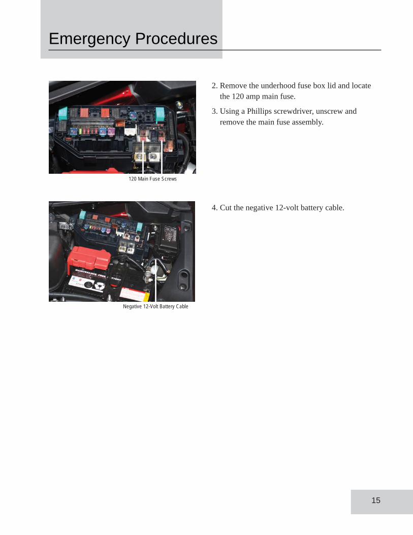
2. Remove the underhood fuse box lid and locatethe 120 amp main fuse.
3. Using a Phillips screwdriver, unscrew andremove the main fuse assembly.
4. Cut the negative 12-volt battery cable.
15
120 Main Fuse Screws
Negative 12-Volt Battery Cable

Cut ZoneSide Curtain
Airbag Inflators
Emergency Procedures
Cutting into these components can resultin high-voltage electric shock
Cutting into these components should notresult in electric shock
Extricating OccupantsIf you need to cut into the body, or use other Jaws of
Life type of equipment to remove occupants, be sure
to stay within the cut zone indicated in the
illustration below.
16
Emergency TowingIf a damaged or disabled FCX Clarity needs to be
moved a short distance, such as to the side of the
road, and the car can still roll on the ground, shift
the transmission to neutral, then manually push the
car. If the vehicle needs to be towed away from the
area, the preferred method is by flatbed truck.


Copyright © 2008, American Honda Motor Co., Inc.Reorder Number Y0804