Embed Size (px)
Citation preview
ELTSNormal
EmergencyLoad
Emergency Lighting Transfer System (Group 9)
User Manual

2 Electronic Theatre Controls, Inc.
Emergency Lighting Transfer System User Manual 3
Emergency Lighting Transfer System
User Manual
ContentsIntroduction................................................................................................... 5
How to use this manual ........................................................................... 5Codes and standards................................................................................ 5System Diagram....................................................................................... 6
Installation and setup chaptersInstallation..................................................................................................... 7
Unpack and Inspect.................................................................................. 7ELTS Models............................................................................................ 8Mounting the ELTS cabinet...................................................................... 9Installing Remote stations (optional) ...................................................... 11
Connecting power and control wiring to the ELTS cabinet ................... 12Transfer switch, Normal power and lighting load connections .............. 13Control and Sensing wire connections................................................... 15
Testing ......................................................................................................... 18Before you power up for the first time .................................................. 18Turn on system ...................................................................................... 18Functional checkout ............................................................................... 19
Settings ....................................................................................................... 21ELTS timing settings .............................................................................. 21ELTS voltage and frequency settings..................................................... 24
Use and service chaptersOperation..................................................................................................... 25
Automatic operation............................................................................... 25Switching power sources manually ....................................................... 26
Service ......................................................................................................... 27Preventive maintenance......................................................................... 27
Troubleshooting ......................................................................................... 28Emergency or Normal Power Stable LED does not turn on properly..... 28The ELTS will not switch between Normal and Emergency.................. 28Remote stations cannot switch the ELTS.............................................. 29
AppendicesAppendix A: ELTS specifications............................................................... 30Appendix B: Wire connection schematics and diagrams ....................... 31Appendix C: Transfer switch control system schematics....................... 33Appendix D: Transfer switch load switching schematic......................... 34Appendix E: Test and Maintenance Log................................................... 35

4 Electronic Theatre Controls, Inc.
Emergency Lighting Transfer System User Manual 5
Emergency Lighting Transfer System
IntroductionWelcome to ETC’s Emergency Lighting Transfer System (ELTS) User Manual. This manual shows you how to install and use your ELTS system. See ELTSModels on page 8 for a breakdown of ELTS models and configurations.
How to use this manualThis manual is divided into three sections:
▼ Installation on page 7 tells you how to install and test your system
▼ Operation on page 25 tells you how to use and service your system
▼ The Appendix B: Wire connection schematics and diagrams on page 31 contains additional information you may need
Warnings and notice conventionsThese symbols alert you to danger or important information:
Warning! Warns you when electricity may cause injury
Warning! Warns you when there is a possibility of other types of injury
Notice: Alerts you to important information relating to equipment performance or reliability
Contacting ETCFor questions about ELTS system delivery or general information, contact ETC Customer Service at 800/688-4116.
Codes and standardsELTS systems meet the following regulatory standards for emergency lighting transfer devices:
▼ ANSI/UL 1008 – Listed, Automatic Transfer Switches
▼ ANSI/NFPA 110 – Emergency and Standby Power Systems
▼ ANSI/NFPA 70 – National Electric CodeArticle 701 – Legally Required Standby SystemsArticle 700 – Emergency SystemsArticle 540 –11(c) – Motion Picture HousesArticle 520 – 7 – Theatres and Similar LocationsArticle 518 – 3(c) – Places of Assembly
▼ City of New York, Advisory board, Electrical Department
▼ OSHA
▼ Department of Defense
6 Electronic Theatre Controls, Inc.
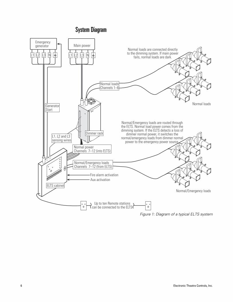
System Diagram
Figure 1: Diagram of a typical ELTS system
Normal/Emergency loads
Normal/Emergency loads are routed throughthe ELTS. Normal load power comes from thedimming system. If the ELTS detects a loss of
dimmer normal power, it switches thenormal/emergency loads from dimmer normal
power to the emergency power source.
Main power
L1 L2 L3 N
Emergencygenerator
L1 L2 L3 N
Normal power Channels 7–12 (into ELTS)
Normal/Emergency loads Channels 7–12 (from ELTS)
Normal loads
Normal loads are connected directlyto the dimming system. If main power
fails, normal loads are dark.
Fire alarm activationAux activation
Normal loadsChannels 1–6
Up to ten Remote stationscan be connected to the ELTS
L1, L2 and L3sensing wires
GeneratorStart
ELTS cabinet
Dimmer rack
Emergency Lighting Transfer System User Manual 7
InstallationUnpack and Inspect
Before you begin installation, check your shipment so you know it arrived complete and undamaged.
1. Check the shipping container for obvious physical damage:
▼ Torn or opened containers
▼ Water stains or wetness
▼ Crushed or punctured boxes
▼ Other shipping-related damage
2. If you find damage, document it to help with a claim against your shipper.
3. Unpack your order and check the contents against the Bill of Materials to be sure your order is complete.
4. Open the ELTS cabinet door and check for loose connections or broken components caused by shipping vibration.
5. If you discover a problem with your order, call ETC Customer Service at 800/688-4116.
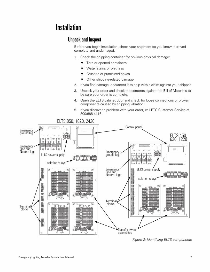
Figure 2: Identifying ELTS components
CONTROL PANEL
ASCO GROUP 9
ASCO
POWER
SUPPLY
PSLUG
GROUND DUE TO SHIPPING, MFG. IS NOT RESPONSIBLE FORLOOSE CONNECTIONS, TIGHTEN ALL CONNECTIONS
BEFORE ENERGIZING.
12 POLE TRANSFER SWITCH
TS1
EL4
LL4
LL1
EL1
LN1
EN1
LN2
LL2
EN2
EL2
LL3
EL3
LN3
EN3
LN4
EN4
LL5
EL5
LL6
LN5
EL6
EN5
LN6
EN6
NL4
NL1
NN
2N
N1
NL2
NN
3N
L3N
L5N
N4
NN
6N
L6N
N5
13
2
TS2
12 POLE TRANSFER SWITCH
EL4
LL4
LL1
EL1
LN1
EN1
LN2
LL2
EN2
EL2
LL3
EL3
LN3
EN3
LN4
EN4
LL5
EL5
LL6
LN5
EL6
EN5
LN6
EN6
NL4
NL1
NN
2N
N1
NL2
NN
3N
L3N
L5N
N4
NN
6N
L6N
N5
13
2
TS4
12 POLE TRANSFER SWITCH
EL4
LL4
LL1
EL1
LN1
EN1
LN2
LL2
EN2
EL2
LL3
EL3
LN3
EN3
LN4
EN4
LL5
EL5
LL6
LN5
EL6
EN5
LN6
EN6
NL4
NL1
NN
2N
N1
NL2
NN
3N
L3N
L5N
N4
NN
6N
L6N
N5
13
2
TS3
12 POLE TRANSFER SWITCH
EL4
LL4
LL1
EL1
LN1
EN1
LN2
LL2
EN2
EL2
LL3
EL3
LN3
EN3
LN4
EN4
LL5
EL5
LL6
LN5
EL6
EN5
LN6
EN6
NL4
NL1
NN
2N
N1
NL2
NN
3N
L3N
L5N
N4
NN
6N
L6N
N5
12
11
10
9
8
6
7
4
5
3
1
2
T10
T11
T12
T8
T9
T6
T7
T3
T4
T5
T1
T2
6
5
4
3
1
2
R3
R4
R5
R2
R1
1
3
2
F1
F2
1
3
2 A2
A1
6
5
4
3
1
2
G3
G2
G1
6
5
4
3
1
2
NA
NB
NC
6
5
4
3
1
2
EA
EC
TS11
TS29
TS30
TS10
TS12
TB2
TB1
TB3
9
8
6
7
4
5
3
1
2
13
2
EPDB
A B C N
SR3BSR3BSR3B SR3B
8910 7 6 345 2 1
A B C N
CONTROL PANEL
ASCO GROUP 9
ASCO
POWER
SUPPLY
PSLUG
GROUND DUE TO SHIPPING, MFG. IS NOT RESPONSIBLE FORLOOSE CONNECTIONS, TIGHTEN ALL CONNECTIONS
BEFORE ENERGIZING.
12 POLE TRANSFER SWITCH
TS1
EL4
LL4
LL1
EL1
LN1
EN1
LN2
LL2
EN2
EL2
LL3
EL3
LN3
EN3
LN4
EN4
LL5
EL5
LL6
LN5
EL6
EN5
LN6
EN6
NL4
NL1
NN2
NN1
NL2
NN3
NL3
NL5
NN4
NN6
NL6
NN5
13
2
TS2
12 POLE TRANSFER SWITCH
EL4
LL4
LL1
EL1
LN1
EN1
LN2
LL2
EN2
EL2
LL3
EL3
LN3
EN3
LN4
EN4
LL5
EL5
LL6
LN5
EL6
EN5
LN6
EN6
NL4
NL1
NN2
NN1
NL2
NN3
NL3
NL5
NN4
NN6
NL6
NN5
12
11
10
9
8
6
7
4
5
3
1
2
T10
T11
T12
T8
T9
T6
T7
T3
T4
T5
T1
T2
6
5
4
3
1
2
R3
R4
R5
R2
R1
1
3
2
F1
F2
1
3
2 A2
A1
6
5
4
3
1
2
G3
G2
G1
6
5
4
3
1
2
NA
NB
NC
6
5
4
3
1
2
EA
EC
TS11
TS29
TS30
TS10
TS12
TB2
TB1
TB3
9
8
6
7
4
5
3
1
2
8910 7 6 345 2 1
13
2
EPDB
A B C N
SR3BSR3BSR3B SR3B
A B C N
Control panel
Transfer switch assemblies
Isolation relays
EmergencyLine and Neutral lugs
ELTS power supply
Isolation relays
ELTS power supply
Emergencyground lug
EmergencyLine and Neutral lugs
Emergencyground lug
Terminal blocks
Terminal blocks
ELTS 850, 1820, 2420
ELTS 450, 620, 1220

8 Electronic Theatre Controls, Inc.
ELTS Models
Figure 3: Large and small ELTS cabinets
Remote station (part # 1093A2023)
▼ Provides front panel keyswitch control at remote locations.
▼ Link up to ten stations with parallel wiring.
▼ Normal and Emergency LEDs indicate ELTS status.
Electronic Theatre Controls Inc.
MODEL ELTS
AUTOMATIC TRANSFER SWITCH FOR EMERGENCY SYSTEMS
ISSUE NO. 934
Operational Current: 200A Max 3 Phase
POWERPOWER
UL1008 Listed
Operational Voltage: 120/208v (3p+N+ )
Frequency: 50/60Hz.
Short-circuit current: 10,000 AIC
Electronic Theatre Controls Inc.Middleton, WI Made in USA
C®®
GENERATOR
EMERGENCY POWER
FIRE ALARM
AUXILIARY
NORMAL POWER
TRANSFER SIGNAL
START
TRANSFER SIGNAL
STABLE
STABLE
42 31 86 75 12119 10
EMERGENCYNORMAL AUTO
EMERGENCYOPERATION
NORMALOPERATION
Electronic Theatre Controls Inc.
MODEL ELTS
AUTOMATIC TRANSFER SWITCH FOR EMERGENCY SYSTEMS
ISSUE NO. 934
Operational Current: 200A Max 3 Phase
POWERPOWER
UL1008 Listed
Operational Voltage: 120/208v (3p+N+ )
Frequency: 50/60Hz.
Short-circuit current: 10,000 AIC
Electronic Theatre Controls Inc.Middleton, WI Made in USA
C®®
GENERATOR
EMERGENCY POWER
FIRE ALARM
AUXILIARY
NORMAL POWER
TRANSFER SIGNAL
START
TRANSFER SIGNAL
STABLE
STABLE
42 31 86 75 12119 10
2413 14 15 16 17 18 2119 20 22 23
EMERGENCYNORMAL AUTO
EMERGENCYOPERATION
NORMALOPERATION
Large ELTS cabinet (30" wide x 54" tall x 9" deep) ELTS 850 8 circuits of 50 ampsELTS 1820 18 circuits of 20 ampsELTS 2420 24 circuits of 20 amps
Small ELTS cabinet (30" wide x 36" tall x 9" deep) ELTS 450 4 circuits of 50 ampsELTS 620 6 circuits of 20 ampsELTS 1220 12 circuits of 20 amps
EMERGENCYNORMAL AUTO
EMERGENCYOPERATION
NORMALOPERATION
POWERPOWER
Figure 4: Remote station
Emergency Lighting Transfer System User Manual 9
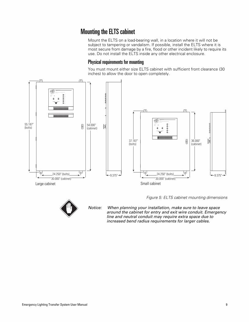
Mounting the ELTS cabinetMount the ELTS on a load-bearing wall, in a location where it will not be subject to tampering or vandalism. If possible, install the ELTS where it is most secure from damage by a fire, flood or other incident likely to require its use. Do not install the ELTS inside any other electrical enclosure.
Physical requirements for mountingYou must mount either size ELTS cabinet with sufficient front clearance (30 inches) to allow the door to open completely.
Figure 5: ELTS cabinet mounting dimensions
Notice: When planning your installation, make sure to leave space around the cabinet for entry and exit wire conduit. Emergency line and neutral conduit may require extra space due to increased bend radius requirements for larger cables.
30.000" (cabinet)24.250" (bolts)
37.187"(bolts)
36.000"(cabinet)
9.375"
Electronic Theatre Controls Inc.
MODEL ELTS
AUTOMATIC TRANSFER SWITCH FOR EMERGENCY SYSTEMS
ISSUE NO. 934
Operational Current: 200A Max 3 Phase
POWERPOWER
UL1008 Listed
Operational Voltage: 120/208v (3p+N+ )
Frequency: 50/60Hz.
Short-circuit current: 10,000 AIC
Electronic Theatre Controls Inc.Middleton, WI Made in USA
C®®
GENERATOR
EMERGENCY POWER
FIRE ALARM
AUXILIARY
NORMAL POWER
TRANSFER SIGNAL
START
TRANSFER SIGNAL
STABLE
STABLE
42 31 86 75 12119 10
EMERGENCYNORMAL AUTO
EMERGENCYOPERATION
NORMALOPERATION
Electronic Theatre Controls Inc.
MODEL ELTS
AUTOMATIC TRANSFER SWITCH FOR EMERGENCY SYSTEMS
ISSUE NO. 934
Operational Current: 200A Max 3 Phase
POWERPOWER
UL1008 Listed
Operational Voltage: 120/208v (3p+N+ )
Frequency: 50/60Hz.
Short-circuit current: 10,000 AIC
Electronic Theatre Controls Inc.Middleton, WI Made in USA
C®®
GENERATOR
EMERGENCY POWER
FIRE ALARM
AUXILIARY
NORMAL POWER
TRANSFER SIGNAL
START
TRANSFER SIGNAL
STABLE
STABLE
42 31 86 75 12119 10
2413 14 15 16 17 18 2119 20 22 23
EMERGENCYNORMAL AUTO
EMERGENCYOPERATION
NORMALOPERATION
30.000" (cabinet)24.250" (bolts)
55.187"(bolts)
54.000"(cabinet)
9.375"
Large cabinet Small cabinet
10 Electronic Theatre Controls, Inc.
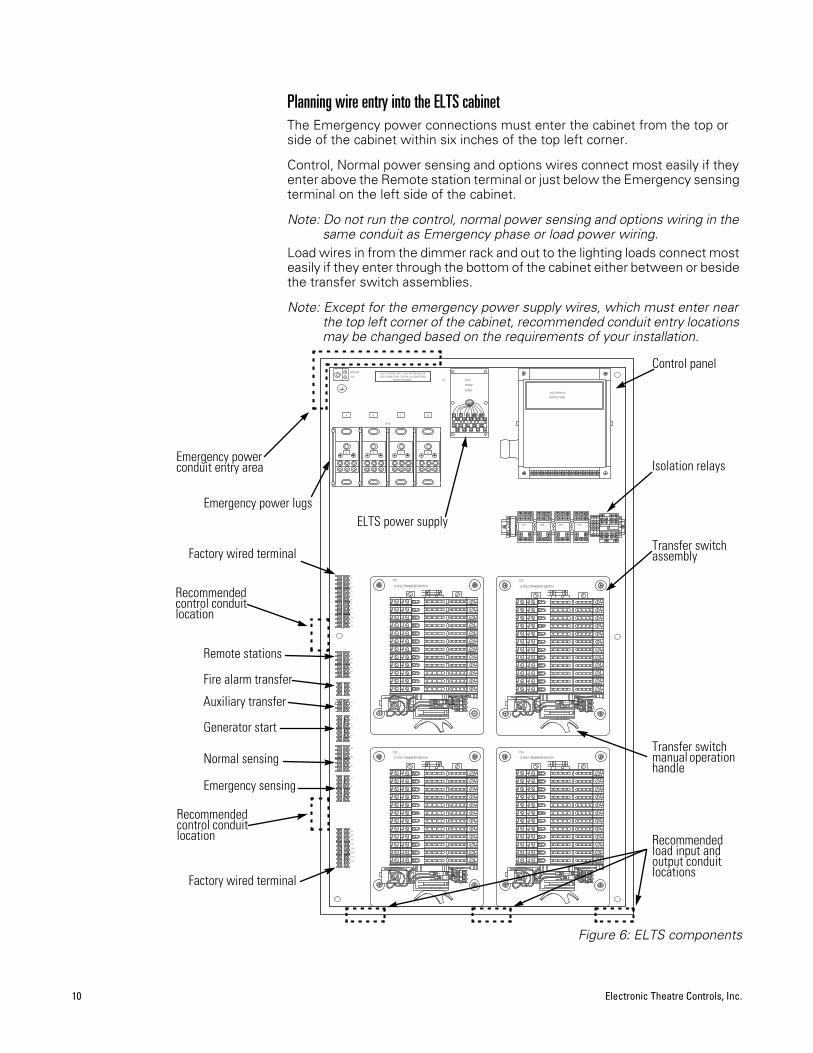
Planning wire entry into the ELTS cabinetThe Emergency power connections must enter the cabinet from the top or side of the cabinet within six inches of the top left corner.
Control, Normal power sensing and options wires connect most easily if they enter above the Remote station terminal or just below the Emergency sensing terminal on the left side of the cabinet.
Note: Do not run the control, normal power sensing and options wiring in the same conduit as Emergency phase or load power wiring.
Load wires in from the dimmer rack and out to the lighting loads connect most easily if they enter through the bottom of the cabinet either between or beside the transfer switch assemblies.
Note: Except for the emergency power supply wires, which must enter near the top left corner of the cabinet, recommended conduit entry locations may be changed based on the requirements of your installation.
Figure 6: ELTS components
CONTROL PANEL
ASCO GROUP 9
ASCO
POWER
SUPPLY
PSLUG
GROUND DUE TO SHIPPING, MFG. IS NOT RESPONSIBLE FORLOOSE CONNECTIONS, TIGHTEN ALL CONNECTIONS
BEFORE ENERGIZING.
12 POLE TRANSFER SWITCH
TS1
EL4
LL4
LL1
EL1
LN1
EN1
LN2
LL2
EN2
EL2
LL3
EL3
LN3
EN3
LN4
EN4
LL5
EL5
LL6
LN5
EL6
EN5
LN6
EN6
NL4
NL1
NN2
NN1
NL2
NN3
NL3
NL5
NN4
NN6
NL6
NN5
13
2
TS2
12 POLE TRANSFER SWITCH
EL4
LL4
LL1
EL1
LN1
EN1
LN2
LL2
EN2
EL2
LL3
EL3
LN3
EN3
LN4
EN4
LL5
EL5
LL6
LN5
EL6
EN5
LN6
EN6
NL4
NL1
NN2
NN1
NL2
NN3
NL3
NL5
NN4
NN6
NL6
NN5
13
2
TS4
12 POLE TRANSFER SWITCH
EL4
LL4
LL1
EL1
LN1
EN1
LN2
LL2
EN2
EL2
LL3
EL3
LN3
EN3
LN4
EN4
LL5
EL5
LL6
LN5
EL6
EN5
LN6
EN6
NL4
NL1
NN2
NN1
NL2
NN3
NL3
NL5
NN4
NN6
NL6
NN5
13
2
TS3
12 POLE TRANSFER SWITCH
EL4
LL4
LL1
EL1
LN1
EN1
LN2
LL2
EN2
EL2
LL3
EL3
LN3
EN3
LN4
EN4
LL5
EL5
LL6
LN5
EL6
EN5
LN6
EN6
NL4
NL1
NN2
NN1
NL2
NN3
NL3
NL5
NN4
NN6
NL6
NN5
12
11
10
9
8
6
7
4
5
3
1
2
T10
T11
T12
T8
T9
T6
T7
T3
T4
T5
T1
T2
6
5
4
3
1
2
R3
R4
R5
R2
R1
1
3
2
F1
F2
1
3
2 A2
A1
6
5
4
3
1
2
G3
G2
G1
6
5
4
3
1
2
NA
NB
NC
6
5
4
3
1
2
EA
EC
TS11
TS29
TS30
TS10
TS12
TB2
TB1
TB3
9
8
6
7
4
5
3
1
2
8910 7 6 345 2 1
A B C N
13
2
EPDB
A B C N
SR3BSR3BSR3B SR3B
Emergency power lugs
Control panel
Transfer switch manual operation handle
Remote stations
Fire alarm transfer
Auxiliary transfer
Generator start
Normal sensing
Emergency sensing
Transfer switch assembly
Emergency power conduit entry area
Recommendedcontrol conduit location
Recommendedcontrol conduit location Recommended
load input and output conduit locations
ELTS power supply
Isolation relays
Factory wired terminal
Factory wired terminal
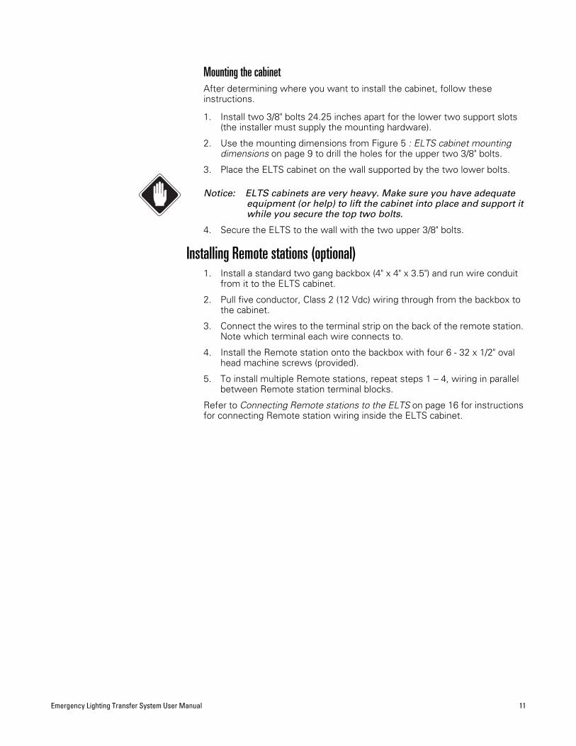
Emergency Lighting Transfer System User Manual 11
Mounting the cabinetAfter determining where you want to install the cabinet, follow these instructions.
1. Install two 3/8" bolts 24.25 inches apart for the lower two support slots (the installer must supply the mounting hardware).
2. Use the mounting dimensions from Figure 5 : ELTS cabinet mounting dimensions on page 9 to drill the holes for the upper two 3/8" bolts.
3. Place the ELTS cabinet on the wall supported by the two lower bolts.
Notice: ELTS cabinets are very heavy. Make sure you have adequate equipment (or help) to lift the cabinet into place and support it while you secure the top two bolts.
4. Secure the ELTS to the wall with the two upper 3/8" bolts.
Installing Remote stations (optional)1. Install a standard two gang backbox (4" x 4" x 3.5") and run wire conduit
from it to the ELTS cabinet.
2. Pull five conductor, Class 2 (12 Vdc) wiring through from the backbox to the cabinet.
3. Connect the wires to the terminal strip on the back of the remote station. Note which terminal each wire connects to.
4. Install the Remote station onto the backbox with four 6 - 32 x 1/2" oval head machine screws (provided).
5. To install multiple Remote stations, repeat steps 1 – 4, wiring in parallel between Remote station terminal blocks.
Refer to Connecting Remote stations to the ELTS on page 16 for instructions for connecting Remote station wiring inside the ELTS cabinet.
12 Electronic Theatre Controls, Inc.
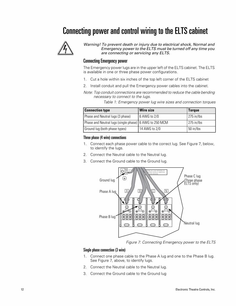
Connecting power and control wiring to the ELTS cabinetWarning! To prevent death or injury due to electrical shock, Normal and
Emergency power to the ELTS must be turned off any time you are connecting or servicing any ELTS.
Connecting Emergency powerThe Emergency power lugs are in the upper left of the ELTS cabinet. The ELTS is available in one or three phase power configurations.
1. Cut a hole within six inches of the top left corner of the ELTS cabinet
2. Install conduit and pull the Emergency power cables into the cabinet.
Note: Top conduit connections are recommended to reduce the cable bending necessary to connect to the lugs.
Table 1: Emergency power lug wire sizes and connection torques
Three phase (4 wire) connections1. Connect each phase power cable to the correct lug. See Figure 7, below,
to identify the lugs.
2. Connect the Neutral cable to the Neutral lug.
3. Connect the Ground cable to the Ground lug.
Figure 7: Connecting Emergency power to the ELTS
Single phase connection (3 wire)1. Connect one phase cable to the Phase A lug and one to the Phase B lug.
See Figure 7, above, to identify lugs.
2. Connect the Neutral cable to the Neutral lug.
3. Connect the Ground cable to the Ground lug
Connection type Wire size Torque
Phase and Neutral lugs (3 phase) 6 AWG to 2/0 275 in/lbs
Phase and Neutral lugs (single phase) 6 AWG to 250 MCM 275 in/lbs
Ground lug (both phase types) 14 AWG to 2/0 50 in/lbs
NCBA
LUG
GROUND DUE TO SHIPPING, MFG. IS NOT RESPONSIBLE FORLOOSE CONNECTIONS, TIGHTEN ALL CONNECTIONS
BEFORE ENERGIZING.
A B C N
Ground lug
Phase A lug
Phase C lug(Three phase ELTS only)
Phase B lug
Neutral lug
Emergency Lighting Transfer System User Manual 13
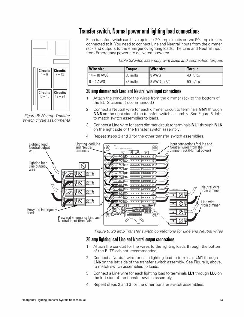
Transfer switch, Normal power and lighting load connectionsEach transfer switch can have up to six 20 amp circuits or two 50 amp circuits connected to it. You need to connect Line and Neutral inputs from the dimmer rack and outputs to the emergency lighting loads. The Line and Neutral input from Emergency power are delivered prewired.
Table 2Switch assembly wire sizes and connection torques
20 amp dimmer rack Load and Neutral wire input connections1. Attach the conduit for the wires from the dimmer rack to the bottom of
the ELTS cabinet (recommended.)
2. Connect a Neutral wire for each dimmer circuit to terminals NN1 through NN6 on the right side of the transfer switch assembly. See Figure 8, left, to match switch assemblies to loads.
3. Connect a Line wire for each dimmer circuit to terminals NL1 through NL6on the right side of the transfer switch assembly.
4. Repeat steps 2 and 3 for the other transfer switch assemblies.
Figure 9: 20 amp Transfer switch connections for Line and Neutral wires
20 amp lighting load Line and Neutral output connections1. Attach the conduit for the wires to the lighting loads through the bottom
of the ELTS cabinet (recommended).
2. Connect a Neutral wire for each lighting load to terminals LN1 through LN6 on the left side of the transfer switch assembly. See Figure 8, above, to match switch assemblies to loads.
3. Connect a Line wire for each lighting load to terminals LL1 through LL6 onthe left side of the transfer switch assembly
4. Repeat steps 2 and 3 for the other transfer switch assemblies.
Wire size Torque Wire size Torque
14 – 10 AWG 35 in/lbs 8 AWG 40 in/lbs
6 – 4 AWG 45 in/lbs 3 AWG to 2/0 50 in/lbs
Circuits1 – 6
Circuits7 – 12
Circuits13 – 18
Circuits19 – 24
Figure 8: 20 amp Transferswitch circuit assignments
12 POLE TRANSFER SWITCH
TS1
EL4
LL4
LL1
EL1
LN1
EN1
LN2
LL2
EN2
EL2
LL3
EL3
LN3
EN3
LN4
EN4
LL5
EL5
LL6
LN5
EL6
EN5
LN6
EN6
NL4
NL1
NN
2N
N1
NL2
NN
3N
L3N
L5N
N4
NN
6N
L6N
N5
13
2
NL1
NN
2N
N1
NL2
LL5
EL5
LL6
LN5
EL6
EN5
LN6
EN6
Line wire from dimmer
Neutral wire from dimmer
Input connections for Line and Neutral wires from the dimmer rack (Normal power)
Lighting load Neutral output wire
Prewired Emergency Line and Neutral input terminals
Lighting load Line output wire
Lighting load Line and Neutral terminals
Prewired Emergency feeds
14 Electronic Theatre Controls, Inc.
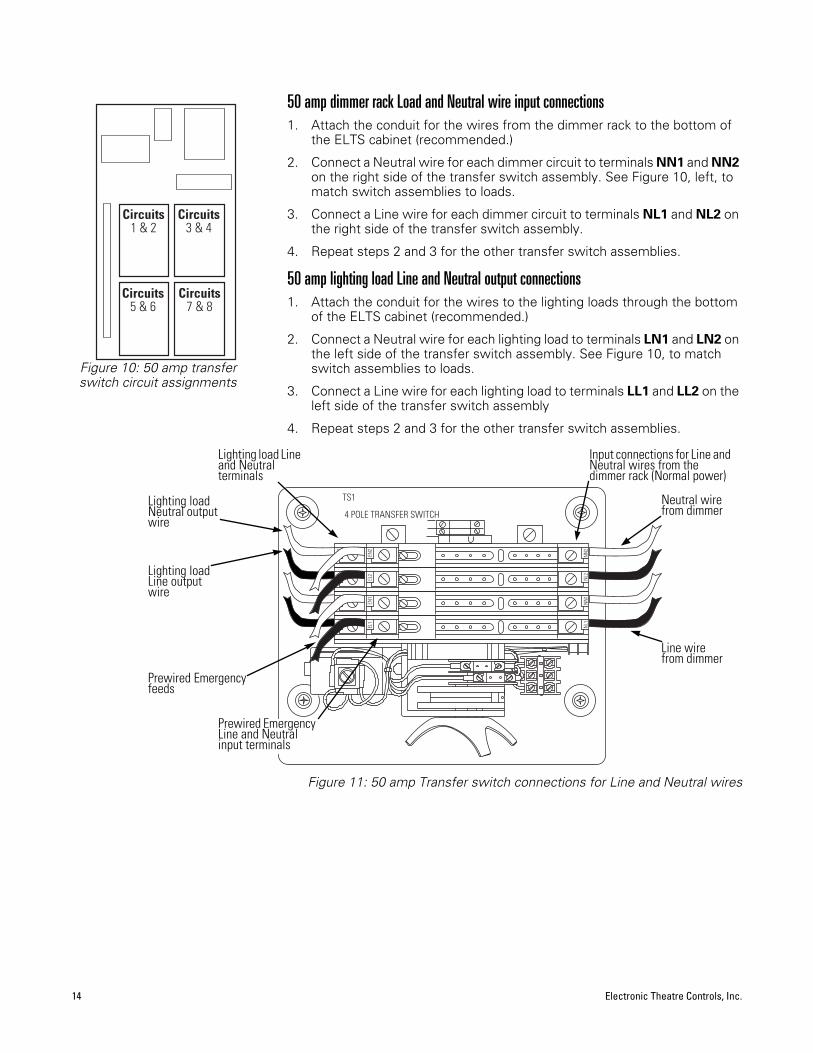
50 amp dimmer rack Load and Neutral wire input connections1. Attach the conduit for the wires from the dimmer rack to the bottom of
the ELTS cabinet (recommended.)
2. Connect a Neutral wire for each dimmer circuit to terminals NN1 and NN2on the right side of the transfer switch assembly. See Figure 10, left, to match switch assemblies to loads.
3. Connect a Line wire for each dimmer circuit to terminals NL1 and NL2 onthe right side of the transfer switch assembly.
4. Repeat steps 2 and 3 for the other transfer switch assemblies.
50 amp lighting load Line and Neutral output connections1. Attach the conduit for the wires to the lighting loads through the bottom
of the ELTS cabinet (recommended.)
2. Connect a Neutral wire for each lighting load to terminals LN1 and LN2 onthe left side of the transfer switch assembly. See Figure 10, to match switch assemblies to loads.
3. Connect a Line wire for each lighting load to terminals LL1 and LL2 on the left side of the transfer switch assembly
4. Repeat steps 2 and 3 for the other transfer switch assemblies.
Figure 11: 50 amp Transfer switch connections for Line and Neutral wires
Circuits1 & 2
Circuits3 & 4
Circuits5 & 6
Circuits7 & 8
Figure 10: 50 amp transferswitch circuit assignments
13
2
4 POLE TRANSFER SWITCH
TS1
LL1
EL1
LN1
EN1
LN2
LL2
EN2
EL2
NL1
NN
2N
N1
NL2
Line wire from dimmer
Neutral wire from dimmer
Input connections for Line and Neutral wires from the dimmer rack (Normal power)
Lighting load Neutral output wire
Prewired Emergency Line and Neutral input terminals
Lighting load Line output wire
Lighting load Line and Neutral terminals
Prewired Emergency feeds
Emergency Lighting Transfer System User Manual 15
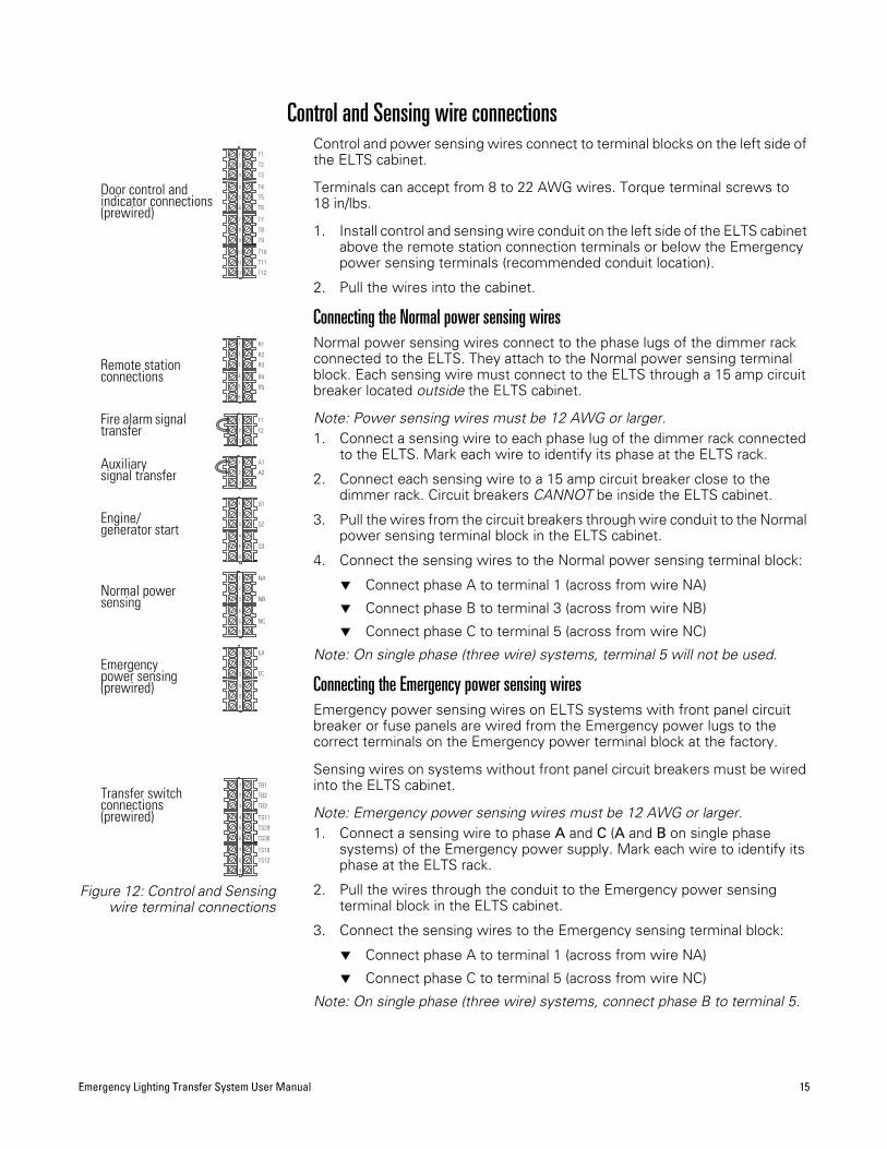
Control and Sensing wire connectionsControl and power sensing wires connect to terminal blocks on the left side of the ELTS cabinet.
Terminals can accept from 8 to 22 AWG wires. Torque terminal screws to 18 in/lbs.
1. Install control and sensing wire conduit on the left side of the ELTS cabinet above the remote station connection terminals or below the Emergency power sensing terminals (recommended conduit location).
2. Pull the wires into the cabinet.
Connecting the Normal power sensing wiresNormal power sensing wires connect to the phase lugs of the dimmer rack connected to the ELTS. They attach to the Normal power sensing terminal block. Each sensing wire must connect to the ELTS through a 15 amp circuit breaker located outside the ELTS cabinet.
Note: Power sensing wires must be 12 AWG or larger.1. Connect a sensing wire to each phase lug of the dimmer rack connected
to the ELTS. Mark each wire to identify its phase at the ELTS rack.
2. Connect each sensing wire to a 15 amp circuit breaker close to the dimmer rack. Circuit breakers CANNOT be inside the ELTS cabinet.
3. Pull the wires from the circuit breakers through wire conduit to the Normal power sensing terminal block in the ELTS cabinet.
4. Connect the sensing wires to the Normal power sensing terminal block:
▼ Connect phase A to terminal 1 (across from wire NA)
▼ Connect phase B to terminal 3 (across from wire NB)
▼ Connect phase C to terminal 5 (across from wire NC)
Note: On single phase (three wire) systems, terminal 5 will not be used.
Connecting the Emergency power sensing wiresEmergency power sensing wires on ELTS systems with front panel circuit breaker or fuse panels are wired from the Emergency power lugs to the correct terminals on the Emergency power terminal block at the factory.
Sensing wires on systems without front panel circuit breakers must be wired into the ELTS cabinet.
Note: Emergency power sensing wires must be 12 AWG or larger.1. Connect a sensing wire to phase A and C (A and B on single phase
systems) of the Emergency power supply. Mark each wire to identify its phase at the ELTS rack.
2. Pull the wires through the conduit to the Emergency power sensing terminal block in the ELTS cabinet.
3. Connect the sensing wires to the Emergency sensing terminal block:
▼ Connect phase A to terminal 1 (across from wire NA)
▼ Connect phase C to terminal 5 (across from wire NC)
Note: On single phase (three wire) systems, connect phase B to terminal 5.
1 F1
TS11
TS29
TS30
TS10
TS12
EA
TB2
TB1
TB3
EC
G3
NA
NB
NC
A2
G2
G1
A1
F2
3
2
R3
R4
R56
5
4
3
T10
T11
T12
R2
R11
2
T8
T9
T6
T7
T3
T4
T5
T1
T2
1
3
2
6
5
4
3
1
2
6
5
4
3
1
2
9
8
6
7
4
5
3
1
2
12
11
10
9
8
6
7
4
5
3
1
2
6
5
4
3
1
2
Figure 12: Control and Sensingwire terminal connections
Door control and indicator connections (prewired)
Remote station connections
Fire alarm signal transfer
Auxiliarysignal transfer
Engine/generator start
Normal power sensing
Emergencypower sensing (prewired)
Transfer switch connections(prewired)

16 Electronic Theatre Controls, Inc.
Connecting the Engine/generator starting wiresThe ELTS system can provide both normally open and normally closed starting circuits for engine generator activation.
1. Connect two wires to the terminals of your engine/generator starting circuit.
Note: Consult your generator installation manual for start signal wiring information.
2. Pull the wires through the conduit to the engine/generator start terminal block.
3. Connect one of the starting wires to terminal 3 (across from wire G2).
4. Connect the other starting wire to terminal 1 or 5:
▼ For a closed start signal, connect the wires to terminal 1 (across from wire G1)
▼ For an open start signal, connect the wires to terminal 5 (across from wire G3)
Connecting Remote stations to the ELTSYou can connect up to 10 Remote stations to the ELTS with parallel wiring. For Remote station installation instructions see page 11.
1. Pull the Remote station wires the Remote station terminal.
2. Connect the Remote wire 1 (Common) to terminal 1
3. Connect the Remote wire 2 (Normal Select) to terminal 3
4. Connect the Remote wire 3 (Emergency Select) to terminal 2
5. Connect the Remote wire 4 (Normal indicator LED) to terminal 4
6. Connect the Remote wire 5 (Emergency indicator LED) to terminal 5
G3
G2
G1
6
5
4
3
1
2
Figure 13: Connectionsfor Engine/generator
starting wires
Closed start signal
Open start signal
Alwaysconnected
R3
R4
R56
5
4
3
R2
R11
2
Figure 14: Connectionsfor Remote stations
Remote 1
Remote 3
Remote 5
Remote 4
Remote 2
Emergency Lighting Transfer System User Manual 17
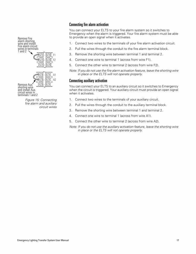
Connecting fire alarm activationYou can connect your ELTS to your fire alarm system so it switches to Emergency when the alarm is triggered. Your fire alarm system must be able to provide an open signal when it activates.
1. Connect two wires to the terminals of your fire alarm activation circuit.
2. Pull the wires through the conduit to the fire alarm terminal block.
3. Remove the shorting wire between terminal 1 and terminal 2.
4. Connect one wire to terminal 1 (across from wire F1).
5. Connect the other wire to terminal 2 (across from wire F2).
Note: If you do not use the fire alarm activation feature, leave the shorting wire in place or the ELTS will not operate properly.
Connecting auxiliary activationYou can connect your ELTS to an auxiliary circuit so it switches to Emergency when the circuit is triggered. Your auxiliary circuit must provide an open signal when it activates.
1. Connect two wires to the terminals of your auxiliary circuit.
2. Pull the wires through the conduit to the auxiliary terminal block.
3. Remove the shorting wire between terminal 1 and terminal 2.
4. Connect one wire to terminal 1 (across from wire A1).
5. Connect the other wire to terminal 2 (across from wire A2).
Note: If you do not use the auxiliary activation feature, leave the shorting wire in place or the ELTS will not operate properly.
1 F1
A2
A1
F2
3
2
1
3
2
Figure 15: Connectingfire alarm and auxiliary
circuit wires
Remove Aux. shorting wire and install Aux. circuit wires in terminals 1 and 2
Remove Fire alarm shorting wire and install Fire alarm circuit wires in terminals 1 and 2
18 Electronic Theatre Controls, Inc.
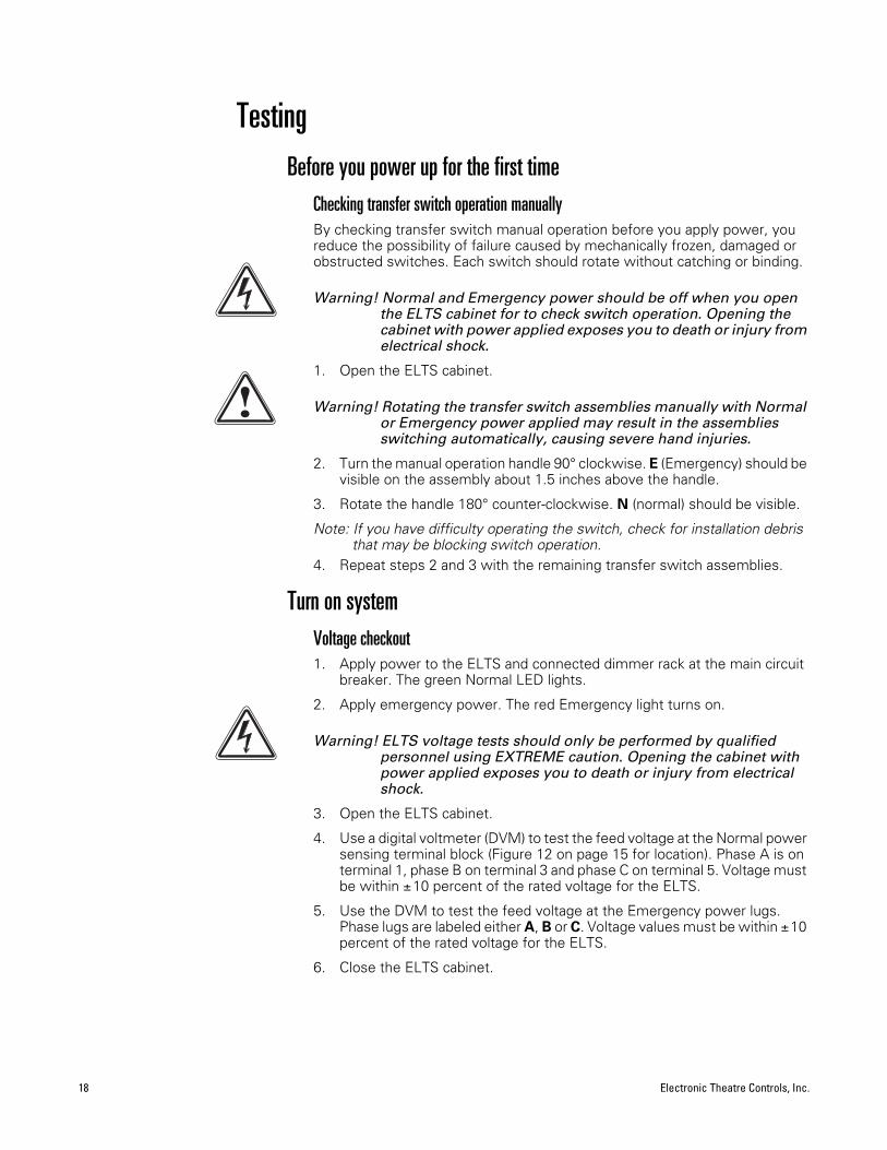
TestingBefore you power up for the first time
Checking transfer switch operation manually By checking transfer switch manual operation before you apply power, you reduce the possibility of failure caused by mechanically frozen, damaged or obstructed switches. Each switch should rotate without catching or binding.
Warning! Normal and Emergency power should be off when you open the ELTS cabinet for to check switch operation. Opening the cabinet with power applied exposes you to death or injury from electrical shock.
1. Open the ELTS cabinet.
Warning! Rotating the transfer switch assemblies manually with Normal or Emergency power applied may result in the assemblies switching automatically, causing severe hand injuries.
2. Turn the manual operation handle 90 clockwise. E (Emergency) should be visible on the assembly about 1.5 inches above the handle.
3. Rotate the handle 180 counter-clockwise. N (normal) should be visible.
Note: If you have difficulty operating the switch, check for installation debris that may be blocking switch operation.
4. Repeat steps 2 and 3 with the remaining transfer switch assemblies.
Turn on systemVoltage checkout1. Apply power to the ELTS and connected dimmer rack at the main circuit
breaker. The green Normal LED lights.
2. Apply emergency power. The red Emergency light turns on.
Warning! ELTS voltage tests should only be performed by qualified personnel using EXTREME caution. Opening the cabinet with power applied exposes you to death or injury from electrical shock.
3. Open the ELTS cabinet.
4. Use a digital voltmeter (DVM) to test the feed voltage at the Normal power sensing terminal block (Figure 12 on page 15 for location). Phase A is on terminal 1, phase B on terminal 3 and phase C on terminal 5. Voltage must be within 10 percent of the rated voltage for the ELTS.
5. Use the DVM to test the feed voltage at the Emergency power lugs. Phase lugs are labeled either A, B or C. Voltage values must be within 10percent of the rated voltage for the ELTS.
6. Close the ELTS cabinet.
Emergency Lighting Transfer System User Manual 19
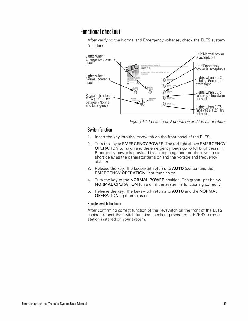
Functional checkoutAfter verifying the Normal and Emergency voltages, check the ELTS system functions.
Figure 16: Local control operation and LED indications
Switch function1. Insert the key into the keyswitch on the front panel of the ELTS.
2. Turn the key to EMERGENCY POWER. The red light above EMERGENCYOPERATION turns on and the emergency loads go to full brightness. If Emergency power is provided by an engine/generator, there will be a short delay as the generator turns on and the voltage and frequency stabilize.
3. Release the key. The keyswitch returns to AUTO (center) and the EMERGENCY OPERATION light remains on.
4. Turn the key to the NORMAL POWER position. The green light below NORMAL OPERATION turns on if the system is functioning correctly.
5. Release the key. The keyswitch returns to AUTO and the NORMALOPERATION light remains on.
Remote switch functionsAfter confirming correct function of the keyswitch on the front of the ELTS cabinet, repeat the switch function checkout procedure at EVERY remote station installed on your system.
Operational Current: 200A Max 3 Phase
Electronic Theatre Controls Inc.MODEL ELTS
AUTOMATIC TRANSFER SWITCH FOR EMERGENCY SYSTEMS
ISSUE NO. 934
POWERPOWER
UL1008 Listed
Operational Voltage: 120/208v (3p+N+ )Frequency: 50/60Hz.Short-circuit current: 10,000 AIC
Electronic Theatre Controls Inc.Middleton, WI Made in USA
©®®
GENERATOR
EMERGENCY POWER
FIRE ALARM
AUXILIARY
NORMAL POWER
TRANSFER SIGNAL
START
TRANSFER SIGNAL
STABLE
STABLE
EMERGENCYNORMAL AUTO
EMERGENCYOPERATION
NORMALOPERATION
Lights when Normal power is used
Keyswitch selects ELTS preference between Normal and Emergency
Lights when Emergency power is used
Lit if Normal power is acceptable
Lights when ELTS sends a Generator start signal
Lit if Emergency power is acceptable
Lights when ELTS receives a fire alarm activation
Lights when ELTS receives a auxiliary activation

20 Electronic Theatre Controls, Inc.
Automatic functionThe automatic function tests the ELTS’s ability to switch back and forth from Normal to Emergency when Normal power is interrupted or restored.
1. Make sure the NORMAL OPERATION LED is lit on the ELTS front panel.
2. Turn off the normal power to the dimmer rack connected to the ELTS. The NORMAL OPERATION and NORMAL POWER STABLE LEDs on the ELTS front panel goes out and the ELTS switches to Emergency power (the EMERGENCY OPERATION and EMERGENCY POWER STABLE LEDs light, and the emergency loads go to full brightness.) If Emergency power is provided by an engine/generator, there will be a short delay before switching as the generator turns on and the voltage and frequency stabilize.
3. Turn the Normal power back on. The ELTS switches back to Normal power after the retransfer delay times out (the default setting is one minute). On the front of the ELTS, the EMERGENCY OPERATION and EMERGENCY POWER STABLE LEDs turn off and the NORMALOPERATION and NORMAL POWER STABLE LEDs light. If used, the Emergency power engine/generator turns off when the cool down time is complete.
Options functionELTS systems can also be activated by fire alarm and auxiliary circuits. Both are operated by a normally closed circuit controlled by the fire alarm or auxiliary relays. When the fire alarm or auxiliary circuit activates, the relay opens, causing the ELTS to switch to Emergency power. To test option relay function, either:
▼ Activate the fire alarm or auxiliary relay. The ELTS should switch to Emergency power and the emergency loads should go to full.
▼ If you do not wish to activate the fire alarm or auxiliary circuit, generate an open circuit at the ELTS connection to the fire alarm or auxiliary circuit by disconnecting one of the two wires to the ELTS cabinet. The ELTS will switch to Emergency power and the emergency loads should go to full.
Note: The second method tests the ELTS response to an open circuit, but does not confirm the fire alarm or auxiliary relay’s ability to open the circuit to the ELTS.
Emergency Lighting Transfer System User Manual 21
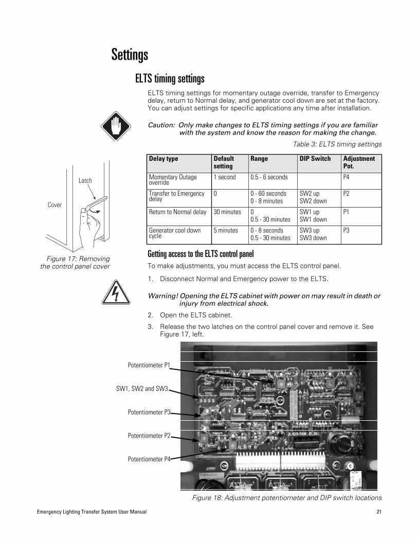
SettingsELTS timing settings
ELTS timing settings for momentary outage override, transfer to Emergency delay, return to Normal delay, and generator cool down are set at the factory. You can adjust settings for specific applications any time after installation.
Caution: Only make changes to ELTS timing settings if you are familiar with the system and know the reason for making the change.
Table 3: ELTS timing settings
Getting access to the ELTS control panel To make adjustments, you must access the ELTS control panel.
1. Disconnect Normal and Emergency power to the ELTS.
Warning! Opening the ELTS cabinet with power on may result in death or injury from electrical shock.
2. Open the ELTS cabinet.
3. Release the two latches on the control panel cover and remove it. See Figure 17, left.
Figure 18: Adjustment potentiometer and DIP switch locations
Delay type Defaultsetting
Range DIP Switch AdjustmentPot.
Momentary Outage override
1 second 0.5 - 6 seconds P4
Transfer to Emergency delay
0 0 - 60 seconds0 - 8 minutes
SW2 upSW2 down
P2
Return to Normal delay 30 minutes 00.5 - 30 minutes
SW1 upSW1 down
P1
Generator cool down cycle
5 minutes 0 - 8 seconds0.5 - 30 minutes
SW3 upSW3 down
P3
Latch
Cover
Figure 17: Removingthe control panel cover
SW1, SW2 and SW3
Potentiometer P1
Potentiometer P2
Potentiometer P3
Potentiometer P4
22 Electronic Theatre Controls, Inc.
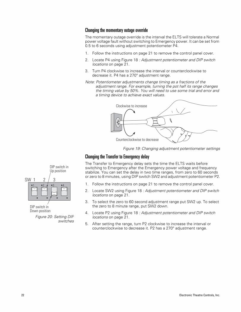
Changing the momentary outage overrideThe momentary outage override is the interval the ELTS will tolerate a Normal power voltage fault without switching to Emergency power. It can be set from 0.5 to 6 seconds using adjustment potentiometer P4.
1. Follow the instructions on page 21 to remove the control panel cover.
2. Locate P4 using Figure 18 : Adjustment potentiometer and DIP switch locations on page 21.
3. Turn P4 clockwise to increase the interval or counterclockwise to decrease it. P4 has a 270 adjustment range.
Note: Potentiometer adjustments change timing as a fractions of the adjustment range. For example, turning the pot half its range changes the timing value by 50%. You will need to use some trial and error and a timing device to achieve exact values.
Figure 19: Changing adjustment potentiometer settings
Changing the Transfer to Emergency delayThe Transfer to Emergency delay sets the time the ELTS waits before switching to Emergency after the Emergency power voltage and frequency stabilize. You can set the delay in two time ranges, from zero to 60 seconds or zero to 8 minutes, using DIP switch SW2 and adjustment potentiometer P2.
1. Follow the instructions on page 21 to remove the control panel cover.
2. Locate SW2 using Figure 18 : Adjustment potentiometer and DIP switch locations on page 21.
3. To select the zero to 60 second adjustment range put SW2 up. To select the zero to 8 minute range, put SW2 down.
4. Locate P2 using Figure 18 : Adjustment potentiometer and DIP switch locations on page 21.
5. After setting the range, turn P2 clockwise to increase the interval or counterclockwise to decrease it. P2 has a 270 adjustment range.
Clockwise to increase
Counterclockwise to decrease
•1 •2 •3 •4
SW 1 2 3
• • • •
DIP switch inUp position
DIP switch inDown position
Figure 20: Setting DIPswitches

Emergency Lighting Transfer System User Manual 23
Changing the Return to Normal delayThe Return to Normal delay sets the time the ELTS waits before switching from Emergency to Normal after Normal power is restored. The delay can be turned off, or set from 0.5 to 30 minutes using DIP switch SW1 and adjustment potentiometer P1.
Note:To disable the delay on a one-time basis (to quickly restart an interrupted performance or for testing purposes) switch the ELTS back to Normal with the front panel Local switch or a Remote keyswitch station.
1. Follow the instructions on page 21 to remove the control panel cover.
2. Locate SW1 using Figure 18 : Adjustment potentiometer and DIP switch locations on page 21.
3. To turn off the delay put SW1 up. To set the range from 0.5 to 30 minutes, put SW1 down.
4. If SW1 is down, locate P2 using Figure 18 : Adjustment potentiometer and DIP switch locations on page 21.
5. Turn P2 clockwise to increase the interval or counterclockwise to decrease it. P2 has a 270 adjustment range.
Changing the Generator cool down intervalThe Generator cool down interval sets the time the ELTS waits before shutting off the Emergency power generator after switching back to Normal power. It can be set from zero to 8 seconds or 0.5 to 30 minutes using DIP switch SW3 and adjustment potentiometer P3.
Caution: Consult your generator user manual for proper cool down times before changing the Generator cool down interval.
1. Follow the instructions on page 21 to remove the control panel cover.
2. Locate SW3 using Figure 18 : Adjustment potentiometer and DIP switch locations on page 21.
3. To make the adjustment range zero to 8 seconds put SW3 up. To make the range 0.5 to 30 minutes, put SW3 down.
4. Locate P3 using Figure 18 : Adjustment potentiometer and DIP switch locations on page 21.
5. After setting the range, turn P3 clockwise to increase the interval or counterclockwise to decrease it. P3 has a 270 adjustment range.
24 Electronic Theatre Controls, Inc.
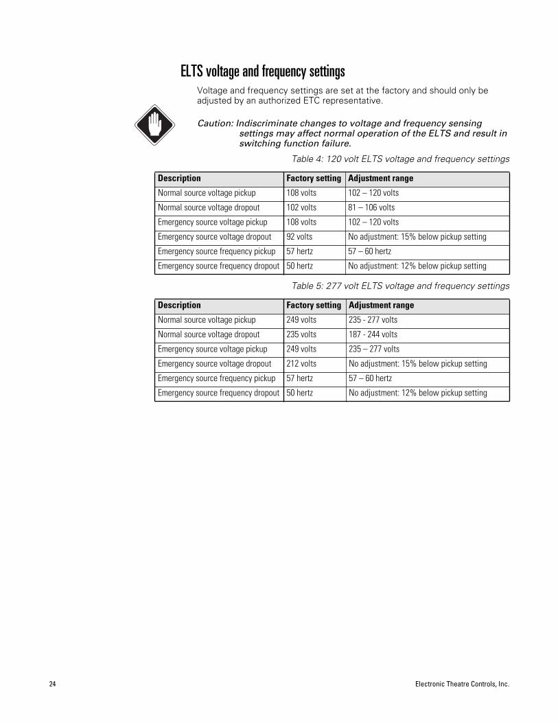
ELTS voltage and frequency settingsVoltage and frequency settings are set at the factory and should only be adjusted by an authorized ETC representative.
Caution: Indiscriminate changes to voltage and frequency sensing settings may affect normal operation of the ELTS and result in switching function failure.
Table 4: 120 volt ELTS voltage and frequency settings
Table 5: 277 volt ELTS voltage and frequency settings
Description Factory setting Adjustment range
Normal source voltage pickup 108 volts 102 – 120 volts
Normal source voltage dropout 102 volts 81 – 106 volts
Emergency source voltage pickup 108 volts 102 – 120 volts
Emergency source voltage dropout 92 volts No adjustment: 15% below pickup setting
Emergency source frequency pickup 57 hertz 57 – 60 hertz
Emergency source frequency dropout 50 hertz No adjustment: 12% below pickup setting
Description Factory setting Adjustment range
Normal source voltage pickup 249 volts 235 - 277 volts
Normal source voltage dropout 235 volts 187 - 244 volts
Emergency source voltage pickup 249 volts 235 – 277 volts
Emergency source voltage dropout 212 volts No adjustment: 15% below pickup setting
Emergency source frequency pickup 57 hertz 57 – 60 hertz
Emergency source frequency dropout 50 hertz No adjustment: 12% below pickup setting
Emergency Lighting Transfer System User Manual 25
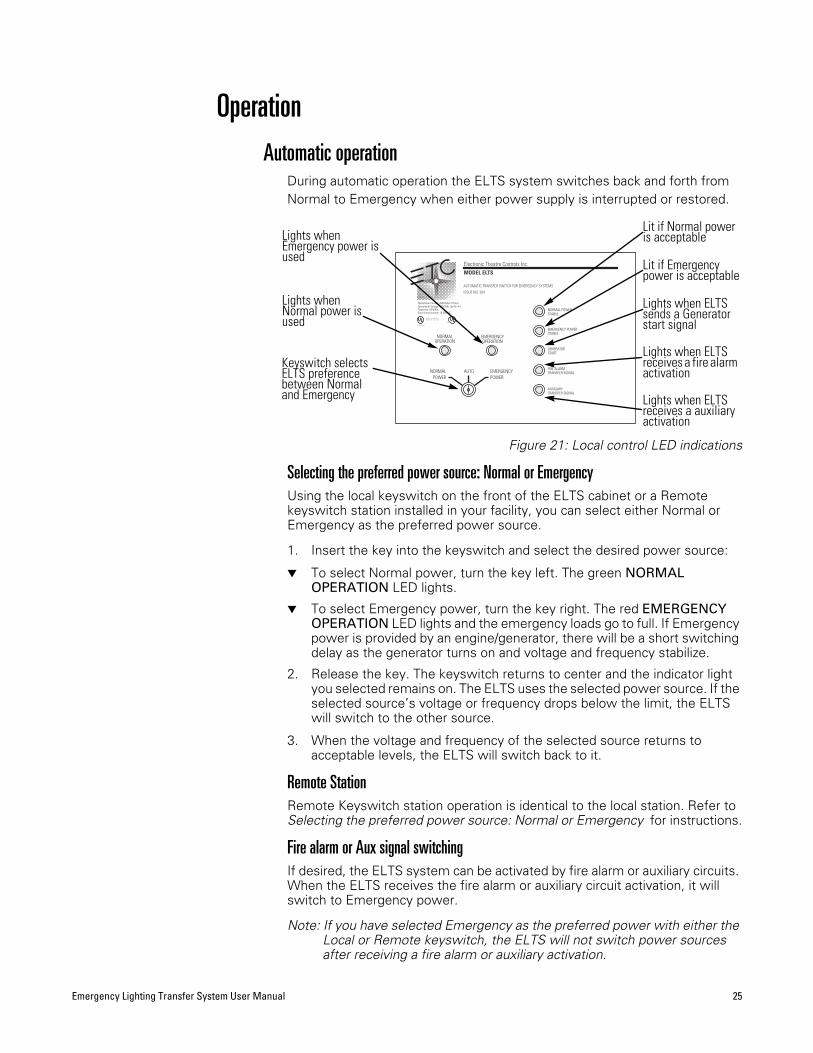
OperationAutomatic operation
During automatic operation the ELTS system switches back and forth from Normal to Emergency when either power supply is interrupted or restored.
Figure 21: Local control LED indications
Selecting the preferred power source: Normal or EmergencyUsing the local keyswitch on the front of the ELTS cabinet or a Remote keyswitch station installed in your facility, you can select either Normal or Emergency as the preferred power source.
1. Insert the key into the keyswitch and select the desired power source:
▼ To select Normal power, turn the key left. The green NORMALOPERATION LED lights.
▼ To select Emergency power, turn the key right. The red EMERGENCYOPERATION LED lights and the emergency loads go to full. If Emergency power is provided by an engine/generator, there will be a short switching delay as the generator turns on and voltage and frequency stabilize.
2. Release the key. The keyswitch returns to center and the indicator light you selected remains on. The ELTS uses the selected power source. If the selected source’s voltage or frequency drops below the limit, the ELTS will switch to the other source.
3. When the voltage and frequency of the selected source returns to acceptable levels, the ELTS will switch back to it.
Remote StationRemote Keyswitch station operation is identical to the local station. Refer to Selecting the preferred power source: Normal or Emergency for instructions.
Fire alarm or Aux signal switchingIf desired, the ELTS system can be activated by fire alarm or auxiliary circuits. When the ELTS receives the fire alarm or auxiliary circuit activation, it will switch to Emergency power.
Note: If you have selected Emergency as the preferred power with either the Local or Remote keyswitch, the ELTS will not switch power sources after receiving a fire alarm or auxiliary activation.
Operational Current: 200A Max 3 Phase
Electronic Theatre Controls Inc.MODEL ELTS
AUTOMATIC TRANSFER SWITCH FOR EMERGENCY SYSTEMS
ISSUE NO. 934
POWERPOWER
UL1008 Listed
Operational Voltage: 120/208v (3p+N+ )Frequency: 50/60Hz.Short-circuit current: 10,000 AIC
Electronic Theatre Controls Inc.Middleton, WI Made in USA
©®®
GENERATOR
EMERGENCY POWER
FIRE ALARM
AUXILIARY
NORMAL POWER
TRANSFER SIGNAL
START
TRANSFER SIGNAL
STABLE
STABLE
EMERGENCYNORMAL AUTO
EMERGENCYOPERATION
NORMALOPERATION
Keyswitch selects ELTS preference between Normal and Emergency
Lit if Normal power is acceptable
Lights when ELTS sends a Generator start signal
Lit if Emergency power is acceptable
Lights when ELTS receives a fire alarm activation
Lights when ELTS receives a auxiliary activation
Lights when Normal power is used
Lights when Emergency power is used

26 Electronic Theatre Controls, Inc.
Switching power sources manuallyIf you need to switch the ELTS from one power source to another when the electronic switching circuits will not function (for example, if you needed to use either Normal or Emergency power, but the voltage or frequency was below the limit) you can set the transfer switch assemblies manually.
1. Disconnect Normal AND Emergency power.
Warning! Turn off Normal and Emergency power to the ELTS at the main circuit breaker.Opening the cabinet with power applied exposes you to death or injury from electrical shock.
2. Open the ELTS cabinet.
3. Disconnect the large brown connector on the lower left side of the control panel.
Figure 22: Removing the control panel connector
Warning! Operating switch assemblies manually without disconnecting the control panel connector may result in the assemblies switching back automatically, causing severe hand injuries.
▼ To switch from Normal to Emergency power: Turn the manual operation handle on the bottom of each transfer switch assembly 90 clockwise. E (Emergency) should be visible just above the handle.
▼ To switch from Emergency to Normal: Turn the manual operation handle on the bottom of each transfer switch assembly 90 counter-clockwise. N (normal) should be visible just above the handle.
4. Close the cabinet door and restore power to the ELTS.
Note: Do not plug the control panel connector back in until you want the ELTS to resume automatic operation.
Restoring automatic operation1. Disconnect Normal AND Emergency power.
Warning! Turn off Normal and Emergency power to the ELTS at the main circuit breaker.Opening the cabinet with power applied exposes you to death or injury from electrical shock.
2. Open the ELTS cabinet.
3. Reconnect the large brown connector on the lower left side of the control panel.
4. Close the cabinet door and restore power to the ELTS.
CONTROL PANEL
ASCO GROUP 9
Squeeze the release tabs on both sides of the socket together and pull the plug out
Emergency Lighting Transfer System User Manual 27
ServicePreventive maintenance
Regular testing and simple maintenance of your ELTS system will result in long service life and reliable performance. To assist in documenting your test and maintenance schedule, a blank Test and Maintenance Log is included on page 35. We suggest you post a copy near your ELTS cabinet.
Warning! Turn off Normal and Emergency power to the ELTS at the main circuit breaker.Opening the cabinet with power applied exposes you to death or injury from electrical shock.
Warning! Rotating the transfer switch assemblies manually with Normal or Emergency power applied may result in the assemblies switching automatically, causing severe hand injuries.
Monthly testing1. Manually test the ELTS’s transfer function at the local keyswitch on the
front of ELTS cabinet. See Switch function on page 19 for keyswitch instructions and indications.
2. Note the test results in the test and maintenance log.
Quarterly testing and maintenance1. Manually test the ELTS’s transfer function at the local keyswitch on the
front of ELTS cabinet. See Switch function on page 19 for keyswitch instructions and indications.
2. Test the ELTS Auto transfer function. See Automatic function on page 20 for automatic transfer instructions and indications.
3. Visually inspect the ELTS cabinet for loose wires or component damage.
4. Note the test results in the test and maintenance log.
Annual testing and maintenance1. Manually test the ELTS’s transfer function at the local keyswitch on the
front of ELTS cabinet. See Switch function on page 19 for keyswitch instructions and indications.
2. Test the ELTS Auto transfer function. See Automatic function on page 20 for automatic transfer instructions and indications.
3. Visually inspect the ELTS cabinet for loose wires or component damage.
4. Retighten ELTS phase, neutral and ground lugs using values in Table 1 :Emergency power lug wire sizes and connection torques on page 12.
5. Vacuum the ELTS cabinet to remove dust and debris that may have collected.
6. Note the test results in the test and maintenance log.
28 Electronic Theatre Controls, Inc.
TroubleshootingIf you have trouble with an installed ELTS system, you can contact ETC Technical Service at 800/775-4382.
Warning! Trouble shooting usually involves opening the ELTS cabinet and metering voltages. Opening the ELTS cabinet with power applied exposes you to death or injury from electrical shock. Use extreme caution during all troubleshooting activities.
Emergency or Normal Power Stable LED does not turn on properlyDuring normal operation, either the Normal Power Stable or Emergency Power Stable LED should be lighted. If one or the other does not light, the problem may be with the LED, Normal or Emergency sensing wiring, or Normal or Emergency power.
1. Switch between Normal and Emergency power on the ELTS control panel keyswitch and observe the results. The ELTS should switch between Normal and Emergency power.
▼ The ELTS switches between Normal and Emergency
1. Check for loose LED wire connections or defective LEDs.
2. Make sure the Control Panel connector is properly seated.
▼ The ELTS does not switch between Normal and Emergency. Go to the next ELTS troubleshooting section.
The ELTS will not switch between Normal and EmergencyIf the system will not switch from Emergency power1. check for tripped Normal power sensing wire circuit breakers.
2. If the circuit breakers are not tripped, meter Normal power using the procedures in Voltage checkout on page 18.
If the system will not switch from Normal power1. Meter Emergency power using the procedures in Voltage checkout on
page 18.
2. If no fire alarm or auxiliary circuits are connected to the ELTS, make sure the terminal jumpers are in place.
3. If fire alarm or auxiliary circuits are connected, meter between the wires to be certain the circuit is closed. An open circuit switches the ELTS to Emergency power.
If the system does not seem to function in either Normal or Emergency power mode1. Make sure the control panel connector is properly seated.
2. Check other wire connections for loose terminals or broken wires.
3. Use the procedures in Checking transfer switch operation manually on page 18 to test the switching mechanism for mechanical problems.
Emergency Lighting Transfer System User Manual 29
Remote stations cannot switch the ELTS 1. Switch between Normal and Emergency power on the ELTS control panel
keyswitch and observe the results.
If the ELTS does not switch locallyFollow the instructions in The ELTS will not switch between Normal and Emergency on page 28.
If the ELTS switches locallyTry switching the ELTS from other Remote station, if multiple stations have been installed
1. If the other stations function, check the wire terminal connections on the problem station. See Installing Remote stations (optional) on page 11 for station connection requirements.
2. If the other stations do not function, or there is only one Remote station installed.
3. Check the wire connections on the Remote station terminal block.
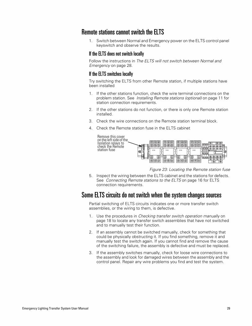
4. Check the Remote station fuse in the ELTS cabinet
Figure 23: Locating the Remote station fuse5. Inspect the wiring between the ELTS cabinet and the stations for defects.
See Connecting Remote stations to the ELTS on page 16 for ELTS connection requirements.
Some ELTS circuits do not switch when the system changes sourcesPartial switching of ELTS circuits indicates one or more transfer switch assemblies, or the wiring to them, is defective.
1. Use the procedures in Checking transfer switch operation manually on page 18 to locate any transfer switch assemblies that have not switched and to manually test their function.
2. If an assembly cannot be switched manually, check for something that could be physically obstructing it. If you find something, remove it and manually test the switch again. If you cannot find and remove the cause of the switching failure, the assembly is defective and must be replaced.
3. If the assembly switches manually, check for loose wire connections to the assembly and look for damaged wires between the assembly and the control panel. Repair any wire problems you find and test the system.
SR3BSR3BSR3B SR3B
Remove this cover on the left side of the Isolation relays to check the Remote station fuse
30 Electronic Theatre Controls, Inc.
Appendix A: ELTS specificationsDimensions
Small cabinet: ELTS 450, ELTS 620, ELTS122036" x 30" x 9" Large cabinet: ELTS 850, ELTS 1820, ELTS 242054" x 30" x 9"
WeightELTS 450, ELTS 620, ELTS1220 – 305 poundsELTS 850, ELTS 1820, ELTS 2420 – 370 pounds
ElectricalOperational voltage
120/240V single phase 250 amp maximum120/208V three phase 175 amp maximum277/480V three phase 175 amp maximumFrequency: 50 – 60HzShort circuit current: 10 kA @ 120/240V
100,000 kA @ 277/480V(5 kA with 50 amp circuit breakers)
Electrical Compliance▼ ANSI/UL 1008 – Listed, Automatic Transfer Switches
▼ ANSI/NFPA 110 – Emergency and Standby Power Systems
▼ ANSI/NFPA 70 – National Electric CodeArticle 701 – Legally Required Standby SystemsArticle 700 – Emergency SystemsArticle 540 –11(c) – Motion Picture HousesArticle 520 – 7 – Theatres and Similar LocationsArticle 518 – 3(c) – Places of Assembly
▼ City of New York, Advisory board, Electrical Department
▼ OSHA
▼ Department of Defense
EnvironmentAmbient temperature between 32 F and 104 F (0 C and 40 C)Humidity between 30 and 95 percent (non-condensing)Altitude below 6500 feet (2000 meters)
Emergency Lighting Transfer System User Manual 31
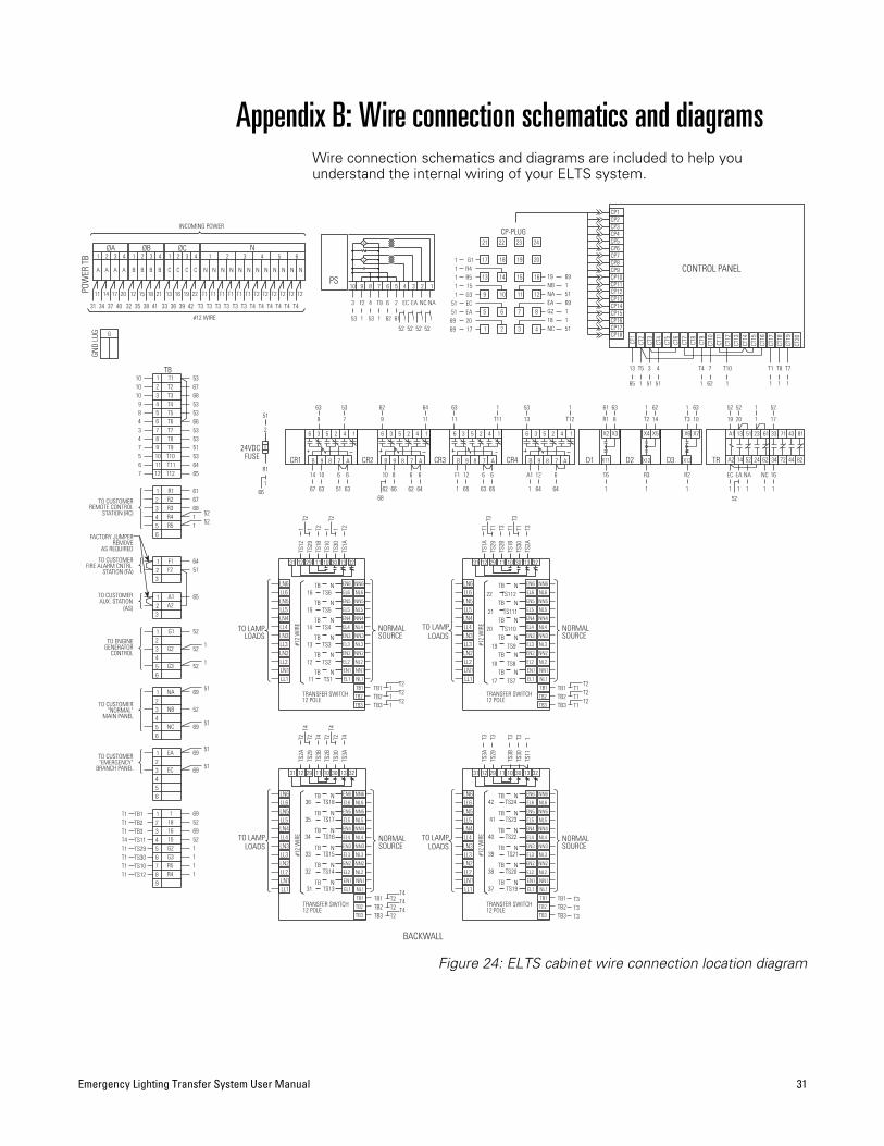
Appendix B: Wire connection schematics and diagramsWire connection schematics and diagrams are included to help you understand the internal wiring of your ELTS system.
Figure 24: ELTS cabinet wire connection location diagram
#12 WIRE
NØCØBØA
INCOMING POWER
1 2 3 4 531311 62 4 2 24 4
POW
ER T
B
T3 T4 T4T4
N
T2
N
T2
N
T2
T4T4T4T3 T3T3
N
T1
N
T2
N
T2
N
T2
N
T1
N
T1
N
T1
A
11
41 42393633 T3 T3
C
19
C
22
N
T1
N
T1
B
21
C
16
C
13
383532
B
18
B
15
B
12
AAA
3
31 403734
201714
G
GND
LUG
10 9 8 7 6 45 3 2 1
+
+
PS
3
53
F2
1
4
53
T9
1
6
62
2
61
EC
1
EA
1
NC
1
NA
1
52 52 52 52
CP1CP2CP3CP4CP5CP6CP7CP8CP9CP10CP11CP12CP13CP14CP15CP16CP17CP18
CONTROL PANEL
CP-PLUG24
20
16
12
8
4
23
19
15
11
7
3
22
18
14
10
6
2
21
17
13
9
5
1
G11R41R51151G31EC51EA5120691769
19 69NB 1NA 51EA 69G2 118 1NC 51
13
65
T5
1
3
51
4
51
T4
1
7
62
T10
1
T1
1
T8
1
T7
1
CT1
CT2
CT3
CT4
CT5
CT6
CT7
CT8
CT9
CT10
CT11
CT12
CT13
CT14
CT15
CT16
CT17
CT18
CT19
CT20
6 3 5 2 4 1
B 9 8 7 A
6 3 5 2 4 1
B 9 8 7 A
6 3 5 2 4 1
B 9 8 7 A
6 3 5 2 4 1
B 9 8 7 A TR
A1
A2
13
14
51
52
23
24
61
62
33
34
71
72
43
44
81
82D1
X2
X11
X3
D2
X4
X12
X5
D3
X6
X13
X7
24VDCFUSE
5
19
52
EA
1
NA
1
NC
1
17
52
EC
1
20
52
1
1
16
1
R1
61
8
63
T2
1
14
62
T3
1
10
63
T6
1
R3
1
R2
1
2
51
R1
1
52
14
67
10
63
6
51
6
63
10
62
8
66
6
62
6
64
F1
1
12
65
6
63
6
65
A1
1
12
64
6
64
9
63
7
53
9
62
11
64
11
63
T11
1
13
53
T12
1
CR1 CR2 CR3 CR4
6668
123456789101112
TBT110 53T210 67T310 68T49 53T58 53T64 66T73 53T84 53T97 51T105 53T116 64T127 65
STATION (RC)REMOTE CONTROL
TO CUSTOMER
654321 R1 61
R2 67R3 68R4 1R5 1
5252
FACTORY JUMPER
TO CUSTOMERFIRE ALARM CNTRL.
STATION (FA)
TO CUSTOMERAUX. STATION
(AS)
REMOVEAS REQUIRED
3
3
12
12
F1 64F2 51
A1 65A2
TO ENGINEGENERATOR
CONTROL
123456
G1 52
G2 52
G3 521
1
123456
NA 69
NB 52
NC 6951
51
TO CUSTOMER"NORMAL"
MAIN PANEL
TO CUSTOMER"EMERGENCY"
BRANCH PANEL 321
456
EA 69
EC 69
51
51
1 6918 5216 6915 52G2 1G3 1R5 1R4 1
TB1T1TB2T1TB3T1TS11T4TS29T1TS30T1TS10T1TS12T1
123456789
TRANSFER SWITCH12 POLE
LOADSNORMALSOURCE
#12
WIR
E
NTB
LL5
LL2
LL1LN1
LN4
LN3LL3
LL4
LN2
LN6
LN5LL6
NTB
NTB
TB1TB2TB3
NTB
NTB
NTBEL1 NL1
EN1 NN1
EL2 NL2
EN2 NN2
EL3 NL3
EN3 NN3
EL4 NL4
EN4 NN4
EL5 NL5
EN5 NN5
EL6 NL6
EN6 NN6
TB2
TB3
TB1
2931 12 11 10 3230 13
TRANSFER SWITCH12 POLE
LOADSNORMALSOURCE
#12
WIR
E
NTB
LL5
LL2
LL1LN1
LN4
LN3LL3
LL4
LN2
LN6
LN5LL6
NTB
NTB
TB1TB2TB3
NTB
NTB
NTBEL1 NL1
EN1 NN1
EL2 NL2
EN2 NN2
EL3 NL3
EN3 NN3
EL4 NL4
EN4 NN4
EL5 NL5
EN5 NN5
EL6 NL6
EN6 NN6
TB2
TB3
TB1
2931 12 11 10 3230 13
TO LAMP
TRANSFER SWITCH12 POLE
LOADSNORMALSOURCE
#12
WIR
E
NTB
LL5
LL2
LL1LN1
LN4
LN3LL3
LL4
LN2
LN6
LN5LL6
NTB
NTB
TB1TB2TB3
NTB
NTB
NTBEL1 NL1
EN1 NN1
EL2 NL2
EN2 NN2
EL3 NL3
EN3 NN3
EL4 NL4
EN4 NN4
EL5 NL5
EN5 NN5
EL6 NL6
EN6 NN6
TB2
TB3
TB1
2931 12 11 10 3230 13
TRANSFER SWITCH12 POLE
LOADSNORMALSOURCE
#12
WIR
E
NTB
LL5
LL2
LL1LN1
LN4
LN3LL3
LL4
LN2
LN6
LN5LL6
NTB
NTB
TB1TB2TB3
NTB
NTB
NTBEL1 NL1
EN1 NN1
EL2 NL2
EN2 NN2
EL3 NL3
EN3 NN3
EL4 NL4
EN4 NN4
EL5 NL5
EN5 NN5
EL6 NL6
EN6 NN6
TB2
TB3
TB1
2931 12 11 10 3230 13
TO LAMP
BACKWALL
TO LAMP
T2 T2
TS12
1TS
291
TS1B
T2TS
101
TS30
1TS
1AT2
TS1A
T1TS
29T1
TS2B
T3TS
1BT1
TS30
T1TS
2AT3
T3 T3
TO LAMP
TS3A
TS29
TS3B
TS30
TS11
TS616
TS515
TS414
TS313
TS212
TS111
TS11222
TS11121
TS11020
TS919
TS818
TS717
TS1836
TS1735
TS1634
TS1533
TS1432
TS1331
TS2442
TS2341
TS2240
TS2139
TS2038
TS1937
111
T2T2T2 T2
T1
T2T2
T1T1
T4T2
T4T4
T2T2
T3T3T3
TS2A
T2TS
29T2
TS3B
T4TS
2BT2
TS30
T2TS
3AT4 T3 T3 T3 T3 1
T4 T4

32 Electronic Theatre Controls, Inc.
Figure 25: ELTS door panel and breaker bracket wire connection schematics
Figure 26: Transfer switch assembly control wire connections schematic
#12 WIRE
#12 WIRE
#12 WIRE
#12 WIRE
A
TB
B
TB
C
TB
A
TB
B
TB
C
TB
A
TB
B
TB
C
TB
A
TB
B
TB
C
TB
A
TB
B
TB
C
TB
A
TB
B
TB
C
TB
A
TB
B
TB
C
TB
A
TB
B
TB
C
TB
TS1
T1
TS2
T1
TS3
T1
TS4
T1
TS5
T1
TS6
T1
TS7
T2
TS8
T2
TS9
T2
TS10
T2
TS11
T2
TS12
T2
TS13
T3
TS14
T3
TS15
T3
TS16
T3
TS17
T3
TS18
T3
TS19
T4
TS20
T4
TS21
T4
TS22
T4
TS23
T4
TS24
T4
CB15CB14CB13 CB24CB20CB19CB18CB16 CB17 CB23CB21 CB22
CB1 CB2 CB3 CB4 CB5 CB6 CB7 CB8 CB9 CB10 CB11 CB12
Breaker bracket schematicDoor panel schematic
KEYSWITCH CIRCUIT
T7 1
T6 4
T8 1
T6 13
T10 1
T9 6
T11 1
T9 75
T12 1
T9 16
T5 1
T1 109
T4 1
T1 8
T2 1
T3 1
T118
NORMAL POWERSTABLE
G
EMERGENCY POWERSTABLE
G
GENERATORSTART
G
FIRE ALARMTRANSFER SIGNAL
R
AUXILIARYTRANSFER SIGNAL
R
EMERGENCYOPERATION
R
NORMALOPERATION
G
ENA
29
3032
3111
1012
1329
30
31
32
11
1012
13
TB1 TB2 TB3
T2T1
TB3TB2TB1
T3
TB3TB2TB1
13
12 10
11 31
32 30
29
T4
TB3TB2TB1
13
12 10
11 31
32 30
29
SEE CONTROL SCHEMATIC DIAGRAM
FACTORY CONNECTIONS
1
2
3
4
5
6
7
TB1
TB2
TB3
TS11
TS29
TS30
TS10
TO CONTROL MODULE
TERMINAL BLOCK8 TS12
TS1A
TS1B TS2B
TS2A
TS3B
TS3A
TB1
TB2
TB3
TS11
TS12
TS10
TS30
TS29

Emergency Lighting Transfer System User Manual 33
Appendix C: Transfer switch control system schematics
R
G
R
G
G
G
RCR4
1 7CR3
1 7
CR3
CR4
9
1
TR
52 51
S6
S2
CR2
9 6
CR1
3 9
NR
NR
CR1
CR2
TR
24 23
CR3
9 6
CT18
CT9
CT8
CT19
CT12
CT2
CT7
7 5
CT16
CT1
CT17
CT15
CT11
NR
CT10
CT14
CT3
CT4
CR4
6 9
CT6
10 8
3
TR
13 14
S2
S3
S4 S1
S5
S6
4
CR2
1 7
CR1
4 7
6
TR
61 62
2
S1 S4
S5
S3
TR
34 33
TR
SE
SE
SE
SE
ER
ER
JMPR
2
JMPR
3 4 6
+
X3
7
INTERNAL JUMPER
NORM.
(KEY OPER)
N A E
REMOTE CONTROL STATION (RC)
ENGINE-GENERATOR
N
E
R1
R2
R3
G
R
N
E R5
R4
T1
SS
PL1
T3
T2
T4
OPEN CONTACTS
CLOSED CONTACT
FROM NORMAL MAIN PANEL
CONTROL
TO
R1
R2
R3
R1
R3
R2
NORMALLY
NORMALLY
COMMANDSTART-RUNENGINE-GEN.
R4
R5
T1
R4
R5
T1
T2
T3
T4
T3
T2
T4
FIRE ALARM STATION (FA)
AUXILIARY STATION (AS)
LOCAL DIAGNOSTIC PNL. (LD)
EMERG.
LOCAL CONTROL STATION (LC)
NORMAL POWER
EMERG POWER
GENERATOR
TRANSFER SIGNALFIRE ALARM
TRANSFER SIGNALAUXILIARY
STABLE
STABLE
START
AUX T12
E
PL2
N
T5
T6
T7
FIRE
GEN T10
T9
T8
T11
REMOVE AS REQUIREDFACTORY JUMPERS
A1
A2
F2
F1
T12
T5
T6
T7
T5
T7
T8
T9
T10
T11
T10
T9
T8
T11
T12
A1
A2
A1
F1
F2
F1
F2
B A
B A
PS
NA
X11
X6
X2
X13
X4
X12
DRAWING
DRAWING
G2
G3
G1
NB
G3
G2
G1
NB
D2
D1
D3
THIS
THIS
NC
NA
X5
X7
8
14
9MANUAL RELAY
MANUAL RELAY
NC SENSE
NA SENSE
NB SENSE
CP8
CP9
CP17
CP11
CP14
CP13
CP4
CP12
TS-NC
TS-NO
B A
B A10
RETRANSFER
TRANSFER
INTERNAL JUMPER
( 24 Vdc OUTPUT )
TEST-NC
TEST-EMG
TS-NORM
N-OK
E-OK
TS
NR
FUSEFAULTSTATIONCONTROLREMOTE
X10
X1
5A
+ +
GND
INHIBIT
+24VDC
ET-NC
GND
BYPASS
MAN-X
DELAY
GND
13 12
TEST-NC
CP
- -
FROM NORMAL MAIN PANEL208 VAC CKT.
( 208 VAC INPUT )
DRAWING
208 VAC CKT.
DUAL INPUT POWER SUPPLY
FROM EMERGENCY BRANCH PANEL
20
EA
THIS
EC
ISOLATION RELAY
ISOLATION RELAY
11
AUX. STATION
FIRE ALARM
-
1
NC
SCHEMATIC DIAGRAMSEE TRANSFER SWITCHTO TRANSFER SWITCH(ES)FACTORY CONNECTION
DRAWING
DRAWING
DRAWING1TB1
DRAWINGTHIS
TB2
TB3
TS29
TS11
TS30
TS10
TS12
THIS 20
16
THIS
THIS
18
17
15
ECA2 A1
19
EA
CONTROL PANEL
CP2
EA SENSE
EC SENSE
CP3
CP1
CP6
CP10 TS-COM
CP16
CP15
CP5
CP7
T6
- DIODE BLOCKS
- SELECTOR SWITCH, KEY OPERATED
- CONNECTION POINT
- TRANSFER SWITCH TERMINAL CONNECTION
- CONNECTOR PLUG TO CONTROL PANEL- TERMINAL BLOCK
- TRANSFER RELAY- POWER SUPPLY- CONTROL RELAY- CONTROL PANEL
- INDICATING LIGHT
D1- D3
SS
TRPS
CR1- CR4
PL1- PL7
EXPLANATION:CP
XXS1
34 Electronic Theatre Controls, Inc.
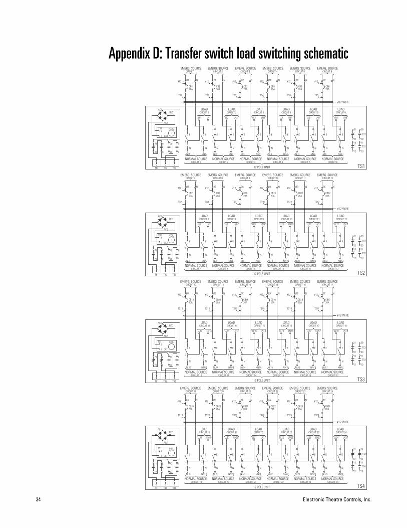
Appendix D: Transfer switch load switching schematic
- +
NORMAL SOURCECIRCUIT 4
EMERG. SOURCE
NORMAL SOURCENL1
EMERG. SOURCE
20ACB1
L
TS1
ØA
CIRCUIT 1 CIRCUIT 2 CIRCUIT 3
12 POLE UNIT
N
E
LOADCIRCUIT 2
N
E
N
NN1
E
L
LL1
CIRCUIT 1
LN1
LOAD
TS2
NORMAL SOURCENL2
N
E
L
NN2
L
20ACB2
LL2
EMERG. SOURCE
N ØB N
NORMAL SOURCE
CIRCUIT 3
LL3
N
E
NL3
L
20ACB3
LN2
TS3
NN3
N
E
L
NL4
N
E
L
LN3
LOAD
TS4
20ACB4
EMERG. SOURCE
ØC N ØA
CIRCUIT 5 CIRCUIT 6
L
EMERG. SOURCE
NORMAL SOURCE
20ACB5
NN4
N
E
L
NL5
N
E
L
LN4
CIRCUIT 4
LL4
LOAD
TS5
NN5
L
N
E
LOADCIRCUIT 5
LL5 LN5
TS6
EMERG. SOURCE
N ØB N
CIRCUIT 6
LN6
NORMAL SOURCENL6
N
E
NN6
N
L
E
20ACB6
LL6
LOAD
NØC
29
11
10
30
TS1
TS1
TS1
32
12
13
31
#12 WIRE
TB3TB1 TB2
9
872
71
B
ATS1
69
70
CKT
AC2
COIL
-
AC1REC+
7
6
#12 #12 #12#12#12#12
CIRCUIT 2CIRCUIT 1 CIRCUIT 3 CIRCUIT 4 CIRCUIT 5 CIRCUIT 6
NORMAL SOURCECIRCUIT 10
EMERG. SOURCE
NORMAL SOURCENL7
EMERG. SOURCE
20ACB7
L
TS7
ØA
CIRCUIT 7 CIRCUIT 8 CIRCUIT 9
12 POLE UNIT
N
E
LOADCIRCUIT 8
N
E
N
NN7
E
L
LL7
CIRCUIT 7
LN7
LOAD
TS8
NORMAL SOURCENL8
N
E
L
NN8
L
20ACB8
LL8
EMERG. SOURCE
N ØB N
NORMAL SOURCE
CIRCUIT 9
LL9
N
E
NL9
L
20ACB9
LN8
TS9
NN9
N
E
L
NL10
N
E
L
LN9
LOAD
TS10
20ACB10
EMERG. SOURCE
ØC N ØA
CIRCUIT 11 CIRCUIT 12
L
EMERG. SOURCE
NORMAL SOURCE
20ACB11
NN10
N
E
L
NL11
N
E
L
LN10
CIRCUIT 10
LL10
LOAD
TS11
NN11
L
N
E
LOADCIRCUIT 11
LL11 LN11
TS12
EMERG. SOURCE
N ØB N
CIRCUIT 12
LN12
NORMAL SOURCENL12
N
E
NN12
N
L
E
20ACB12
LL12
LOAD
NØC
29
11
10
30
TS2
TS2
TS2
32
12
13
31
#12 WIRE
TB3TB1 TB2
9
872
71
B
ATS1
69
70
CKT
AC2
COIL
-
AC1REC+
7
6
#12 #12 #12#12#12#12
CIRCUIT 8CIRCUIT 7 CIRCUIT 9 CIRCUIT 10 CIRCUIT 11 CIRCUIT 12
NORMAL SOURCECIRCUIT 15
EMERG. SOURCE
NORMAL SOURCENL13
EMERG. SOURCE
20ACB13
L
TS13
ØA
CIRCUIT 13 CIRCUIT 14 CIRCUIT 14
12 POLE UNIT
N
E
LOADCIRCUIT 14
N
E
N
NN13
E
L
LL13
CIRCUIT 13
LN13
LOAD
TS14
NORMAL SOURCENL14
N
E
L
NN14
L
20ACB14
LL14
EMERG. SOURCE
N ØB N
NORMAL SOURCE
CIRCUIT 15
LL15
N
E
NL14
L
20ACB15
LN14
TS15
NN14
N
E
L
NL15
N
E
L
LN15
LOAD
TS15
20ACB15
EMERG. SOURCE
ØC N ØA
CIRCUIT 16 CIRCUIT 17
L
EMERG. SOURCE
NORMAL SOURCE
20ACB16
NN15
N
E
L
NL16
N
E
L
LN16
CIRCUIT 16
LL16
LOAD
TS16
NN16
L
N
E
LOADCIRCUIT 17
LL17 LN17
TS17
EMERG. SOURCE
N ØB N
CIRCUIT 18
LN18
NORMAL SOURCENL17
N
E
NN17
N
L
E
20ACB17
LL18
LOAD
NØC
29
11
10
30
TS3
TS3
TS3
32
12
13
31
#12 WIRE
TB3TB1 TB2
9
872
71
B
ATS1
69
70
CKT
AC2
COIL
-
AC1REC+
7
6
#12 #12 #12#12#12#12
CIRCUIT 14CIRCUIT 13 CIRCUIT 15 CIRCUIT 15 CIRCUIT 16 CIRCUIT 17
NORMAL SOURCECIRCUIT 22
EMERG. SOURCE
NORMAL SOURCENL19
EMERG. SOURCE
20ACB19
L
TS19
ØA
CIRCUIT 19 CIRCUIT 20 CIRCUIT 21
12 POLE UNIT
N
E
LOADCIRCUIT 20
N
E
N
NN19
E
L
LL19
CIRCUIT 19
LN19
LOAD
TS20
NORMAL SOURCENL20
N
E
L
NN20
L
20ACB20
LL20
EMERG. SOURCE
N ØB N
NORMAL SOURCE
CIRCUIT 21
LL21
N
E
NL21
L
20ACB21
LN20
TS21
NN21
N
E
L
NL22
N
E
L
LN21
LOAD
TS22
20ACB22
EMERG. SOURCE
ØC N ØA
CIRCUIT 23 CIRCUIT 24
L
EMERG. SOURCE
NORMAL SOURCE
20ACB23
NN22
N
E
L
NL23
N
E
L
LN22
CIRCUIT 22
LL22
LOAD
TS23
NN23
L
N
E
LOADCIRCUIT 23
LL23 LN23
TS24
EMERG. SOURCE
N ØB N
CIRCUIT 24
LN24
NORMAL SOURCENL24
N
E
NN24
N
L
E
20ACB24
LL24
LOAD
NØC
29
11
10
30
TS4
TS41
TS4
32
12
13
31
#12 WIRE
TB3TB1 TB2
9
872
71
B
ATS1
69
70
CKT
AC2
COIL
-
AC1REC+
7
6
#12 #12 #12#12#12#12
CIRCUIT 20CIRCUIT 19 CIRCUIT 21 CIRCUIT 22 CIRCUIT 23 CIRCUIT 24

Emergency Lighting Transfer System User Manual 35
Appendix E: Test and Maintenance LogDate installed ___________________________________________
System address _________________________________________
________________________________________________________
Service contact __________________________________________
Date Inspected by Manual transfer Automatic transfer Visual inspection Vacuumed

Americas 3030 Laura Lane, P.O. Box 620979, Middleton, Wisconsin 53562-0979 USA Tel: +608 831 4116 +800 688 4116 Fax: +608 836 1736 +800 555 8912Europe Unit 5, Victoria Industrial Estate, Victoria Road, London W3 6UU, UK Tel: +44 (0)20 8896 1000 Fax: +44 (0)20 8896 2000Asia Room 605-606, Tower III Enterprise Square, 9 Sheung Yuet Road, Kowloon Bay, Kowloon, Hong Kong Tel: +852 2799 1220 Fax: +852 2799 9325Web: www.etcconnect.com Email: (US) [email protected] (UK) [email protected] (Asia) [email protected]: [email protected] Toll free: 800 775 4382 Comments about this document: [email protected] © 2003 Electronic Theatre Controls, Inc. All Rights Reserved. Product information and specifications subject to change.1093M1101 Rev C Released 01/2003