Embed Size (px)
Citation preview
Emerald Ocean Engineering
Project GreenShores, Phase II Conceptual Design Phase
Prepared for Ecosystem Restoration Support Organization, Inc.
By
David D. McGehee, P.E., M.Oc.E
August 2004
107 Ariola Drive [email protected] Pensacola Beach, FL 32561 (850) 932 – 9111
0
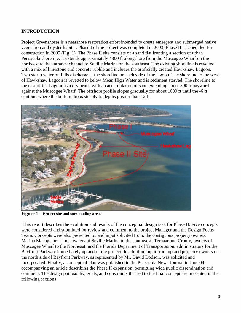
INTRODUCTION Project Greenshores is a nearshore restoration effort intended to create emergent and submerged native vegetation and oyster habitat. Phase I of the project was completed in 2003; Phase II is scheduled for construction in 2005 (Fig. 1). The Phase II site consists of a sand flat fronting a section of urban Pensacola shoreline. It extends approximately 4300 ft alongshore from the Muscogee Wharf on the northeast to the entrance channel to Seville Marina on the southeast. The existing shoreline is revetted with a mix of limestone and concrete rubble and includes the artificially created Hawkshaw Lagoon. Two storm water outfalls discharge at the shoreline on each side of the lagoon. The shoreline to the west of Hawkshaw Lagoon is revetted to below Mean High Water and is sediment starved. The shoreline to the east of the Lagoon is a dry beach with an accumulation of sand extending about 300 ft bayward against the Muscogee Wharf. The offshore profile slopes gradually for about 1000 ft until the -6 ft contour, where the bottom drops steeply to depths greater than 12 ft.
Figure 1 – Project site and surrounding areas This report describes the evolution and results of the conceptual design task for Phase II. Five concepts were considered and submitted for review and comment to the project Manager and the Design Focus Team. Concepts were also presented to, and input solicited from, the contiguous property owners: Marina Management Inc., owners of Seville Marina to the southwest; Terhaar and Cronly, owners of Muscogee Wharf to the Northeast; and the Florida Department of Transportation, administrators for the Bayfront Parkway immediately upland of the project. In addition, input from upland property owners on the north side of Bayfront Parkway, as represented by Mr. David Dodson, was solicited and incorporated. Finally, a conceptual plan was published in the Pensacola News Journal in June 04 accompanying an article describing the Phase II expansion, permitting wide public dissemination and comment. The design philosophy, goals, and constraints that led to the final concept are presented in the following sections
1
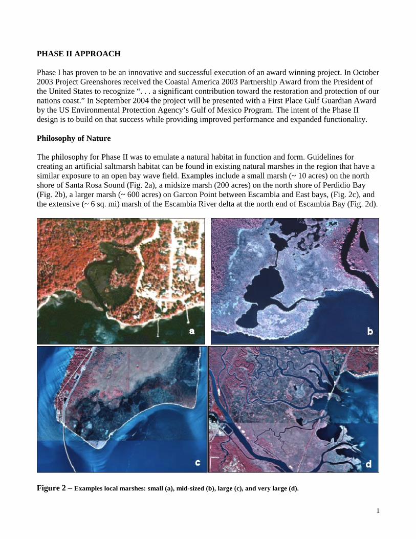
PHASE II APPROACH Phase I has proven to be an innovative and successful execution of an award winning project. In October 2003 Project Greenshores received the Coastal America 2003 Partnership Award from the President of the United States to recognize “. . . a significant contribution toward the restoration and protection of our nations coast.” In September 2004 the project will be presented with a First Place Gulf Guardian Award by the US Environmental Protection Agency’s Gulf of Mexico Program. The intent of the Phase II design is to build on that success while providing improved performance and expanded functionality. Philosophy of Nature The philosophy for Phase II was to emulate a natural habitat in function and form. Guidelines for creating an artificial saltmarsh habitat can be found in existing natural marshes in the region that have a similar exposure to an open bay wave field. Examples include a small marsh (~ 10 acres) on the north shore of Santa Rosa Sound (Fig. 2a), a midsize marsh (200 acres) on the north shore of Perdidio Bay (Fig. 2b), a larger marsh (~ 600 acres) on Garcon Point between Escambia and East bays, (Fig. 2c), and the extensive (~ 6 sq. mi) marsh of the Escambia River delta at the north end of Escambia Bay (Fig. 2d).
Figure 2 – Examples local marshes: small (a), mid-sized (b), large (c), and very large (d).
2
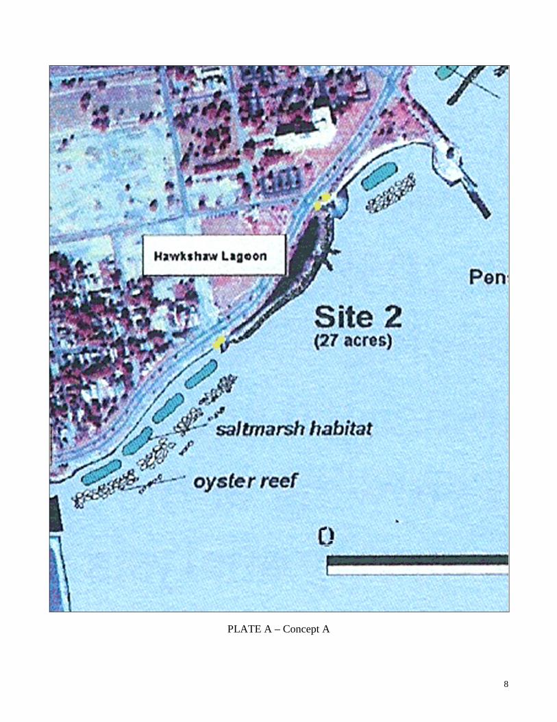
The example marshes share the following features: 1. Shallow sand flats extending offshore that dissipate incident wave energy. The 6-ft contour ranges from several thousand ft to several miles from the shoreline 2. A sandy barrier beach with a berm well above Mean High Water on the bayside shoreline. 3. One or more sinuous waterways, or bayous, that control flood and ebb flows and discharge of storm water from upland drainage areas. 4. Broad banks of saltmarsh, primarily cord grass, growing in sediments with an elevation of approximately mid tide level that extend between the deeper waterways and upland areas. The goals for the final project are to create the maximum amount of productive and sustainable habitat within the project budget, to enrich the quality and enjoyment of the waterfront experience for residents and visitors, and to demonstrate a practical alternative to urban shorelines that enhances, rather than displaces, the natural ecosystem. Discussions and meetings with stakeholders over the period from April through August 2004 provided additional features that would be desirable to incorporate, such as: public beaches, dry bird nesting habitat, improved public access to the project (i.e., walkways and pavilions), fishing access, nature preserve, increased tidal exchange for Hawkshaw Lagoon, and removal of unsightly concrete rubble along the shoreline Constraints and Preliminary Concepts If the saltmarsh was to be created behind the present shoreline, the sand flat could provide adequate wave protection. Since it will be placed on the sand flat itself, protective breakwaters will be required if a meaningful amount of habitat is desired. A single, continuous breakwater across the bayward side of the marsh would provide the maximum protected area, but would require a large volume of construction material. Also, resistance to the impacts of such a monolithic structure on the Bay vista was expressed at various planning meetings. An alternative approach using segmented breakwaters – termed headland breakwaters - has been used with success to provide shore protection at numerous sites around Chesapeake Bay (Hardaway and Gunn, 99; Hardaway et al, 95). The breakwaters protect not only the area directly behind them but, because of diffraction and refraction effects, the shoreline in the gaps between segments. Crescentic beaches form in the gaps between the breakwaters due to the curving wave patterns. The approach can reduce breakwater costs by roughly half, and results in a more natural looking shoreline. Additional environmental and hydrodynamic factors, such as wave climate, were presented in McGehee, 2004 and McGehee, 2001. Concept A was essentially a duplication of the Phase I design at Site II, wherein 3 rows of gappy, segmented breakwaters protected roughly rectangular “pods” of saltmarsh (Plate A). This concept did not receive further consideration for Site II, principally because of the risk of deleterious impacts on the adjacent navigation channel during extreme events (see McGehee 2004).
3
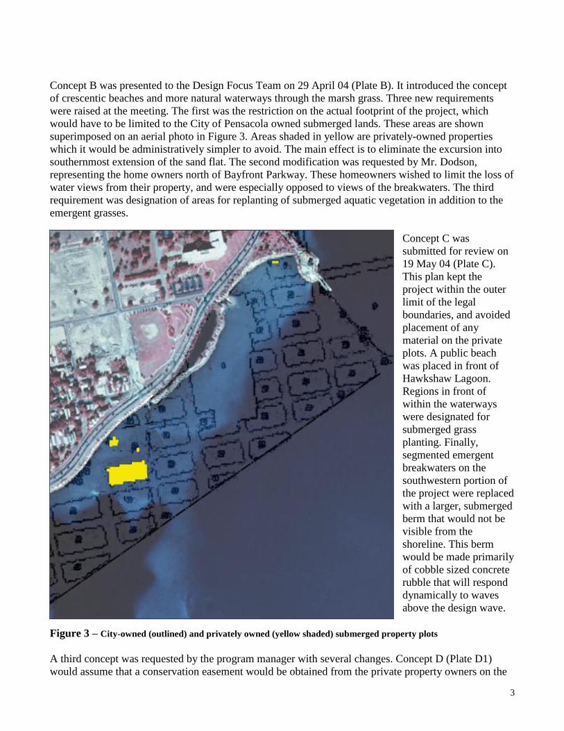
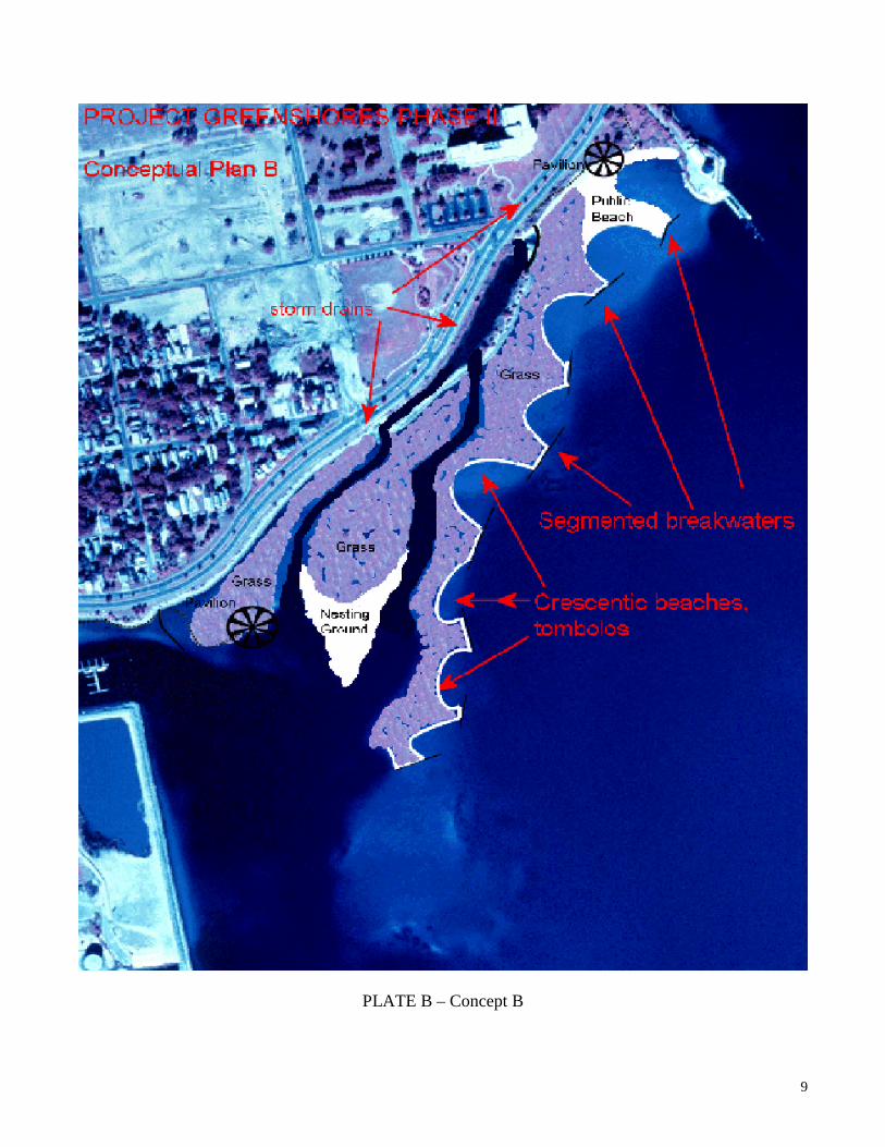
Concept B was presented to the Design Focus Team on 29 April 04 (Plate B). It introduced the concept of crescentic beaches and more natural waterways through the marsh grass. Three new requirements were raised at the meeting. The first was the restriction on the actual footprint of the project, which would have to be limited to the City of Pensacola owned submerged lands. These areas are shown superimposed on an aerial photo in Figure 3. Areas shaded in yellow are privately-owned properties which it would be administratively simpler to avoid. The main effect is to eliminate the excursion into southernmost extension of the sand flat. The second modification was requested by Mr. Dodson, representing the home owners north of Bayfront Parkway. These homeowners wished to limit the loss of water views from their property, and were especially opposed to views of the breakwaters. The third requirement was designation of areas for replanting of submerged aquatic vegetation in addition to the emergent grasses.
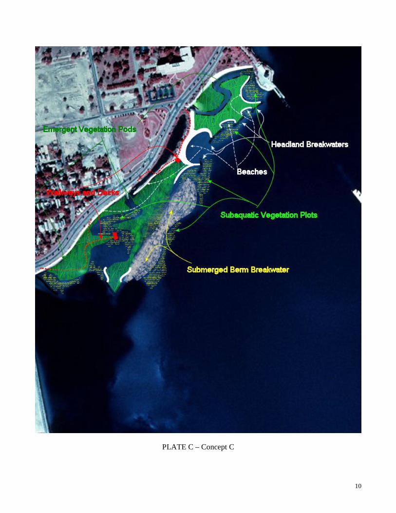
Concept C was submitted for review on 19 May 04 (Plate C). This plan kept the project within the outer limit of the legal boundaries, and avoided placement of any material on the private plots. A public beach was placed in front of Hawkshaw Lagoon. Regions in front of within the waterways were designated for submerged grass planting. Finally, segmented emergent breakwaters on the southwestern portion of the project were replaced with a larger, submerged berm that would not be visible from the shoreline. This berm would be made primarily of cobble sized concrete rubble that will respond dynamically to waves above the design wave.
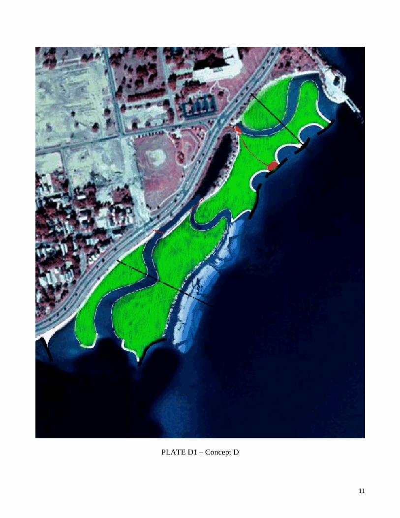
Figure 3 – City-owned (outlined) and privately owned (yellow shaded) submerged property plots A third concept was requested by the program manager with several changes. Concept D (Plate D1) would assume that a conservation easement would be obtained from the private property owners on the

4
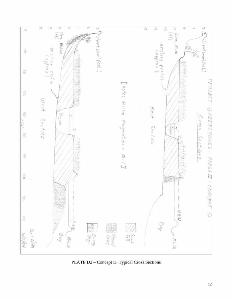
western end of the project. The administrators of the Hawkshaw Lagoon memorial requested the public beach in front of the lagoon be replaced with marsh habitat. A second inlet into Hawkshaw lagoon was requested to improve flushing. A plan for Concept D, including typical cross sections (Plate D2), was provided on 11 June 04. On June 10, a wading survey was performed at the project site, primarily to ascertain the sight distances and visual impacts to vistas of the breakwaters from various upland locations. Subsequent examination of the data revealed that structures eastward of Hawkshaw Lagoon would not be visible from the residences on Bayfront Parkway, and that emergent grasses within a line ~ 400 ft of the shoreline would result in some, but acceptable, impacts on water views. Other modifications requested by the project manager included a continuous waterway between created saltmarsh and the shore, to prevent intermixing with upland vegetation, and more and longer waterways. The final plan, Concept E (Fig. 4, below and Plate E1), best incorporates the project’s philosophy, goals, and requirements within the existing constraints. Features and characteristics of the plan are described below.
Figure 4 – Concept E, plan view
5
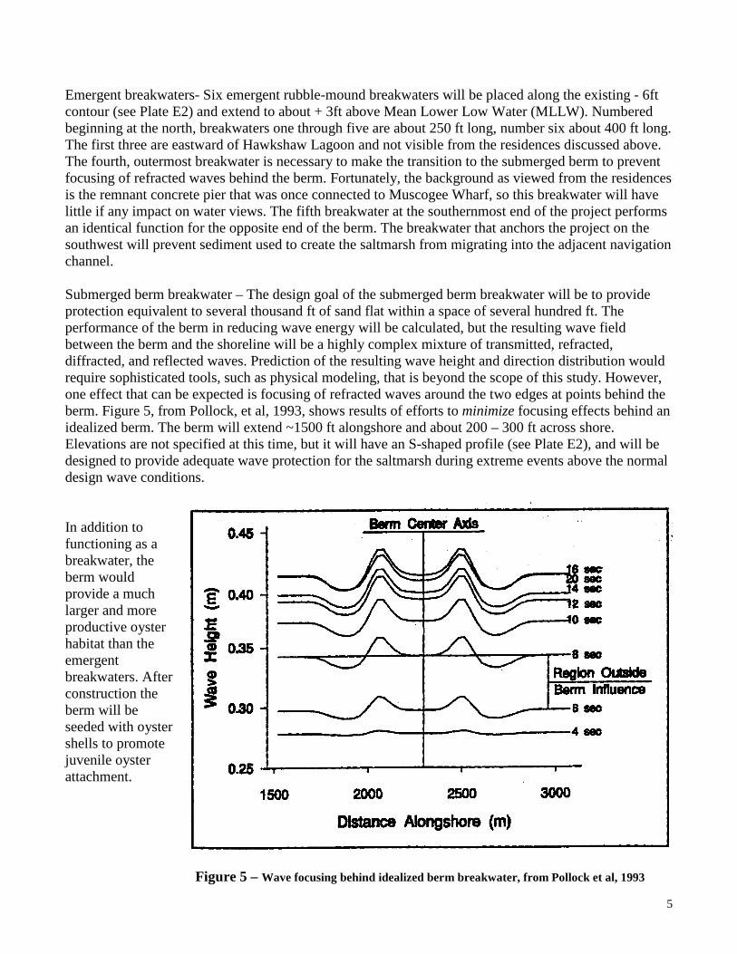
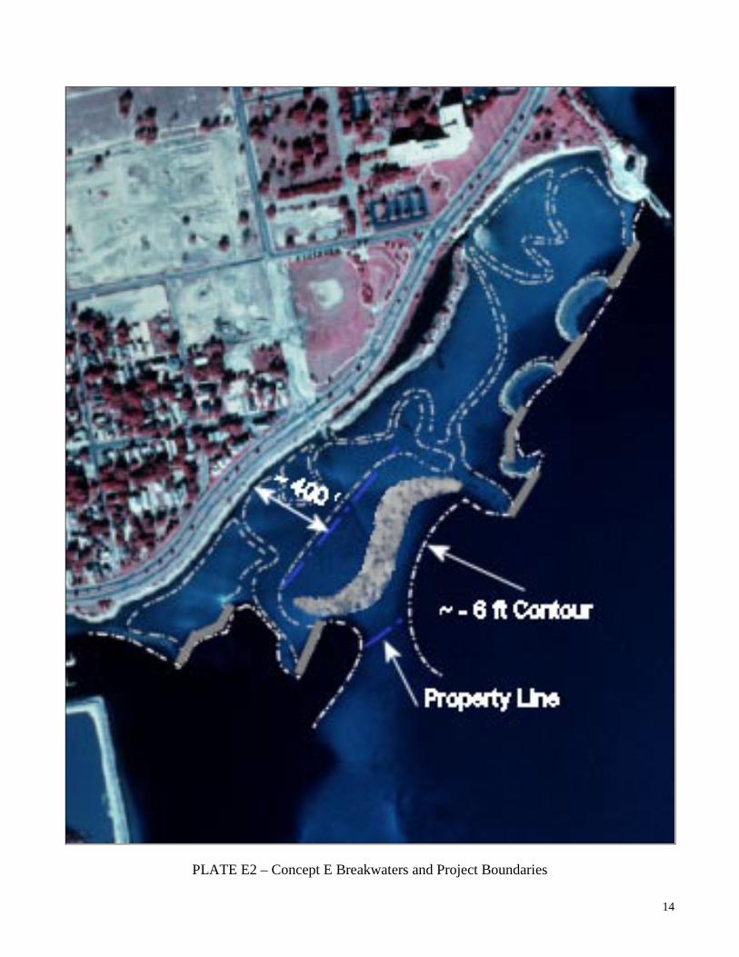
Emergent breakwaters- Six emergent rubble-mound breakwaters will be placed along the existing - 6ft contour (see Plate E2) and extend to about + 3ft above Mean Lower Low Water (MLLW). Numbered beginning at the north, breakwaters one through five are about 250 ft long, number six about 400 ft long. The first three are eastward of Hawkshaw Lagoon and not visible from the residences discussed above. The fourth, outermost breakwater is necessary to make the transition to the submerged berm to prevent focusing of refracted waves behind the berm. Fortunately, the background as viewed from the residences is the remnant concrete pier that was once connected to Muscogee Wharf, so this breakwater will have little if any impact on water views. The fifth breakwater at the southernmost end of the project performs an identical function for the opposite end of the berm. The breakwater that anchors the project on the southwest will prevent sediment used to create the saltmarsh from migrating into the adjacent navigation channel. Submerged berm breakwater – The design goal of the submerged berm breakwater will be to provide protection equivalent to several thousand ft of sand flat within a space of several hundred ft. The performance of the berm in reducing wave energy will be calculated, but the resulting wave field between the berm and the shoreline will be a highly complex mixture of transmitted, refracted, diffracted, and reflected waves. Prediction of the resulting wave height and direction distribution would require sophisticated tools, such as physical modeling, that is beyond the scope of this study. However, one effect that can be expected is focusing of refracted waves around the two edges at points behind the berm. Figure 5, from Pollock, et al, 1993, shows results of efforts to minimize focusing effects behind an idealized berm. The berm will extend ~1500 ft alongshore and about 200 – 300 ft across shore. Elevations are not specified at this time, but it will have an S-shaped profile (see Plate E2), and will be designed to provide adequate wave protection for the saltmarsh during extreme events above the normal design wave conditions.
In addition to functioning as a breakwater, the berm would provide a much larger and more productive oyster habitat than the emergent breakwaters. After construction the berm will be seeded with oyster shells to promote juvenile oyster attachment. Figure 5 – Wave focusing behind idealized berm breakwater, from Pollock et al, 1993
6
Saltmarshes – Approximately 22 acres of emergent saltmarsh will be made by planting Spartina alteniflora on raised sand beds (see Plate E2). The elevation of the beds will be approximately mid tide level, except for the elevated berms of the dry beaches. Beaches - Pocket beaches with peak elevation near + 2 ft MLLW lie in the approximately 200 ft gaps between the segmented breakwaters. Their primary function is wave protection for the saltmarsh behind them, but they can also serve as recreational beaches or as nesting bird habitat. The dry beach directly behind the submerged berm breakwater is unspecified at this time, since prediction of the sediment transport effect of waves after passing over the berm breakwater is beyond the scope of this study. It is likely that a dry beach will form during lower wave conditions and become mobilized during higher wave conditions. If maximum survival of transplanted grass is desired, it is recommended that the sand deposits in this region be allowed to adjust naturally for one year before planting. Waterways (Bayous) – The waterways shape helps to regulate the rate of flood and ebb tidal flows into and over the saltmarsh. At any tide stage above mid tide, the marshes will be completely submerged, but flood and ebb will flows at lower stages will be directed over the banks of the waterways. During large discharge events from the storm water drains, the serpentine pathways force the freshwater outflow over the banks and into the saltmarsh, where it will be slowed, and its suspended sediment load reduced, before reaching the bay. A secondary function of the waterways is as pathways for small recreational craft. It is recommended that motorized craft be restricted from these waterways to avoid bank erosion. Optionally, secondary features, such as logs, stones, or gravel banks can be placed selectively in the waterways to provide additional shelter/habitat for fish. The waterways will be formed from the spaces between the saltmarsh, and for the most part no additional construction will be required. Subsequent sedimentation of the waterways will be most active at the outfall of the storm water drains and the outer ends of the waterways whenever subject to significant wave energy. Existing practices for cleaning out the settlement basins at the storm drain outfalls will likely have to be continued. Placement and orientation of the outer end of the waterways should minimize longshore sediment transport that would tend to close these openings, but some migrating and episodic closures after storms can be anticipated. Hawkshaw Lagoon – The existing opening at Hawkshaw Lagoon will be widened, deepened, and connected to the waterway that parallels the shoreline to improve flushing of the deeper water in the lagoon. The concrete rubble revetment on the present bayside of the barrier will not be needed for wave protection after construction of the project. This rubble will be removed and utilized, after processing, in construction of the berm breakwater. Sub aquatic grasses - Approximately 2 acres of protected water at depths between -3 and -4 ft MLLW will be reserved behind the berm breakwater for replanting and regeneration of sub aquatic vegetation. Public Access – Public access and educational features are not shown on Concept E, but can be added when requested. Suggested facilities include walkways to the recreational beaches, covered and open pavilions, educational displays, and ramps for handicapped access.
7
REFERENCES Hardaway, C.S., Gunn, J.R., and Reynolds, R.N., 1995, Headland Breakwater Performance in Chesapeake Bay. Proceedings of the 1995 National Conference on Beach Preservation and Technology, St Petersburg, FL, 365-382. Hardaway, C.S. and Gunn, J.R. Gunn, 1999, Chesapeake Bay: Design and Early Performance of Three Headland Breakwater Systems. Proceedings of Coastal Sediments ’99, ASCE, Hauppague, NY, 828-843. McGehee, David D., 2001; “Project GreenShores, Phase 1 - Storm Impacts Evaluation,” Contractor Report to the Ecosystem Restoration Support Organization, Inc., Emerald Ocean Engineering, Pensacola, FL, July, 2001 McGehee, David D., 2004, “Project GreenShores, Phase II – Site Description and Hydrodynamic Climate,” Contractor Report to the Ecosystem Restoration Support Organization, Inc., Emerald Ocean Engineering, Pensacola, FL, May, 2004 Pollock , C.E., Allison, M.C., and Williams, G.L., 1993, “Designing Nearshore Berms to Optimize Wave Attenuation,” US Army Engineer Waterways experiment Station, Vicksburg, MS.
8
PLATE A – Concept A
9
PLATE B – Concept B
10
PLATE C – Concept C
11
PLATE D1 – Concept D
12
PLATE D2 – Concept D, Typical Cross Sections

13
Plate E1 – Concept E
14
PLATE E2 – Concept E Breakwaters and Project Boundaries