Embed Size (px)
DESCRIPTION
EMC World
Citation preview

EMC World “Big Data” Lab 101 Guide for Isilon OneFS Clusters

Page intentionally left blank
2
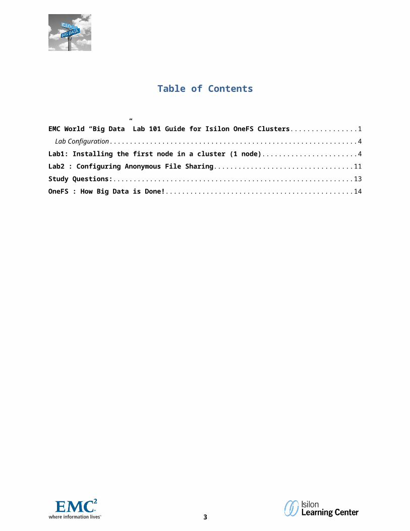
Table of Contents
EMC World “Big Data” Lab 101 Guide for Isilon OneFS Clusters........................................................................1
Lab Configuration.......................................................................................................................................................4
Lab1: Installing the first node in a cluster (1 node)...................................................................................................4
Lab2 : Configuring Anonymous File Sharing..........................................................................................................11
Study Questions:.........................................................................................................................................................13
OneFS : How Big Data is Done!.................................................................................................................................14
3
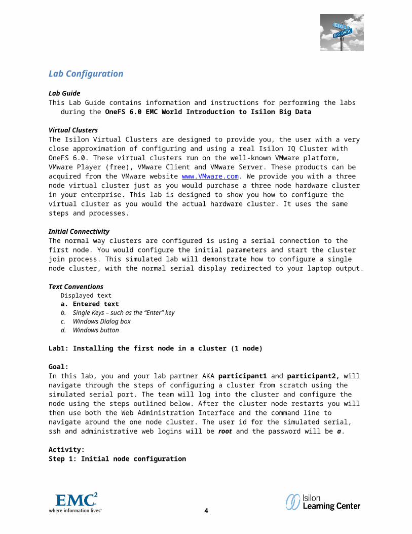
Lab Configuration
Lab GuideThis Lab Guide contains information and instructions for performing the labs during the OneFS 6.0 EMC World
Introduction to Isilon Big Data
Virtual ClustersThe Isilon Virtual Clusters are designed to provide you, the user with a very close approximation of configuring and using a real Isilon IQ Cluster with OneFS 6.0. These virtual clusters run on the well-known VMware platform, VMware Player (free), VMware Client and VMware Server. These products can be acquired from the VMware website www.VMware.com. We provide you with a three node virtual cluster just as you would purchase a three node hardware cluster in your enterprise. This lab is designed to show you how to configure the virtual cluster as you would the actual hardware cluster. It uses the same steps and processes.
Initial ConnectivityThe normal way clusters are configured is using a serial connection to the first node. You would configure the initial parameters and start the cluster join process. This simulated lab will demonstrate how to configure a single node cluster, with the normal serial display redirected to your laptop output.
Text ConventionsDisplayed texta. Entered textb. Single Keys – such as the “Enter” keyc. Windows Dialog boxd. Windows button
Lab1: Installing the first node in a cluster (1 node)
Goal:In this lab, you and your lab partner AKA participant1 and participant2, will navigate through the steps of configuring a cluster from scratch using the simulated serial port. The team will log into the cluster and configure the node using the steps outlined below. After the cluster node restarts you will then use both the Web Administration Interface and the command line to navigate around the one node cluster. The user id for the simulated serial, ssh and administrative web logins will be root and the password will be a.
Activity:Step 1: Initial node configurationEach pair will configure your initial node. If you were at a customer site you’d need to serially connect to the cluster to configure the first node of your cluster.
1. Click on the VMware Workstation Node 1 Tab. Click into the black space area and you can enter information. To leave hold the CTRL + ALT keys together and you are back on the PC interface.
2. We’re going to create a new cluster. Select “Create a new cluster” by typing “1” and pressing the Enter key (Note: if you mess up anything you can always type “back” to step back a step in the wizard)
4
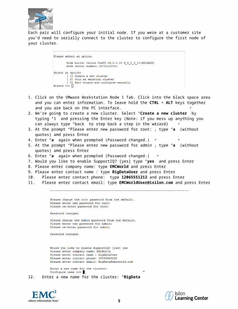
3. At the prompt “Please enter new password for root:”, type “a” (without quotes) and press Enter 4. Enter “a” again when prompted (Password changed.)5. At the prompt “Please enter new password for admin”, type “a” (without quotes) and press Enter 6. Enter “a” again when prompted (Password changed.)7. Would you like to enable SupportIQ? [yes] type “yes” and press Enter8. Please enter company name: type EMCWorld and press Enter9. Please enter contact name : type BigDataUser and press Enter10. Please enter contact phone: type 12065551212 and press Enter11. Please enter contact email: type [email protected] and press Enter
12. Enter a new name for the cluster: “BigData”13. You need to set the “Character Encoding” for the cluster (Note: if you mess up anything you can always type
“back” to step back a step in the wizard)a. Select the default “UTF-8” by just pressing Enter
14. You are now going to configure the Internal-A interface, which is used for inter-node communications. On a normal cluster this would be the Infiniband connections.a. Select “Configure Netmask” by typing “1” and pressing Enterb. Type “255.255.255.0” and press Enter (Example below)c. Select “Configure int-a IP ranges” by typing “3” and pressing Enter (Example below)
5
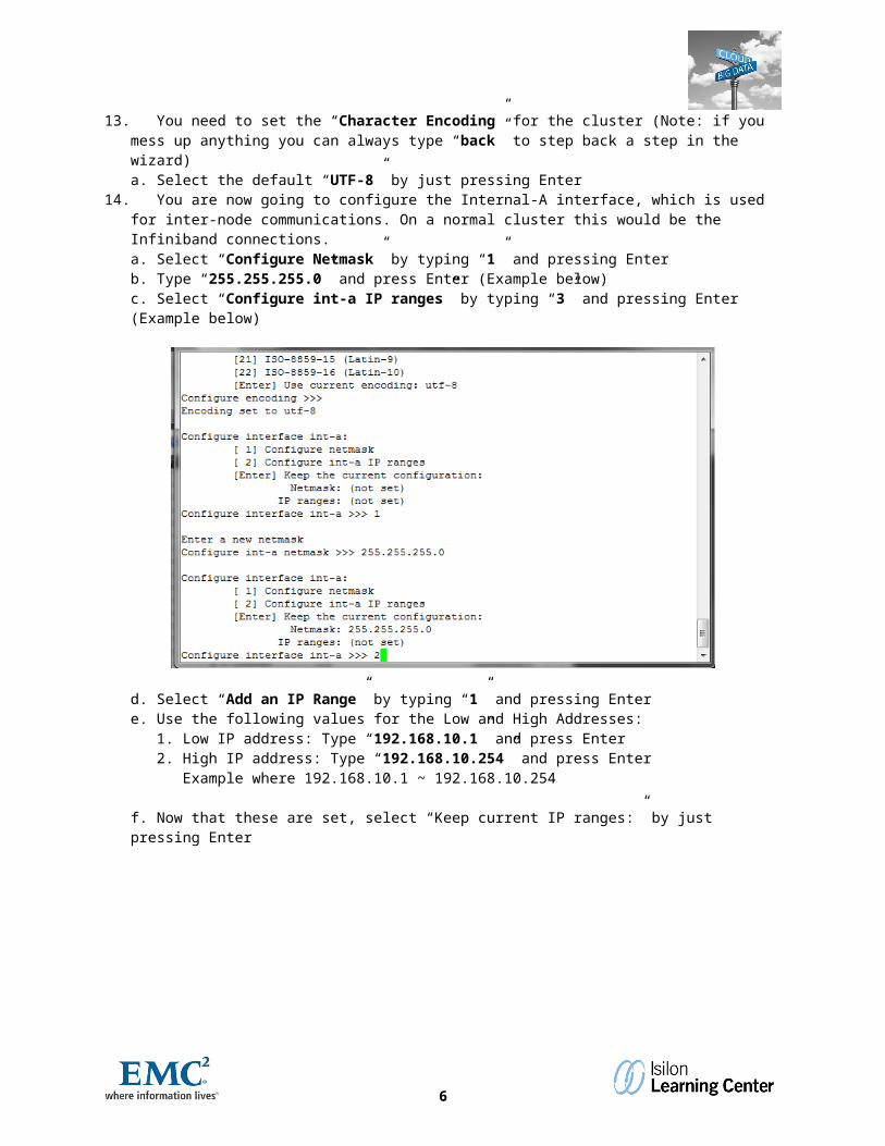
d. Select “Add an IP Range” by typing “1” and pressing Entere. Use the following values for the Low and High Addresses:
1. Low IP address: Type “192.168.10.1” and press Enter2. High IP address: Type “192.168.10.254” and press Enter
Example where 192.168.10.1 ~ 192.168.10.254
f. Now that these are set, select “Keep current IP ranges:” by just pressing Enter
g. Now that you are done creating all the IP ranges needed for this Internal-A interface, select “Keep the current configuration” by just pressing Enter
h. After entering information for Internal-A, you will be presented with options to configure Internal-A or Internal-B. You are only going to be using one internal interface in the lab.
1. Now that you are done with internal networking, select “Finished with internal interfaces” by just pressing Enter
Select the internal interfaces to configure
6
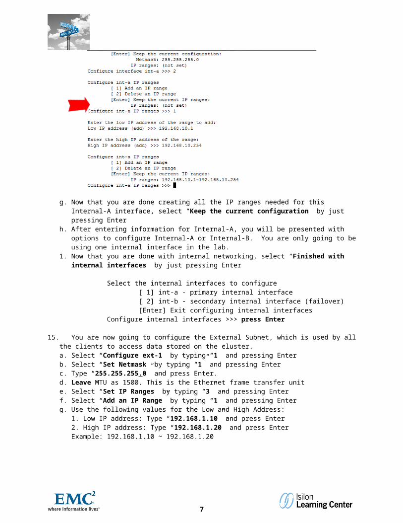
[ 1] int-a - primary internal interface [ 2] int-b - secondary internal interface (failover) [Enter] Exit configuring internal interfacesConfigure internal interfaces >>> press Enter
15. You are now going to configure the External Subnet, which is used by all the clients to access data stored on the cluster.a. Select “Configure ext-1” by typing “1” and pressing Enterb. Select “Set Netmask” by typing “1” and pressing Enterc. Type “255.255.255.0” and press Enter. d. Leave MTU as 1500. This is the Ethernet frame transfer unite. Select “Set IP Ranges” by typing “3” and pressing Enterf. Select “Add an IP Range” by typing “1” and pressing Enterg. Use the following values for the Low and High Address:
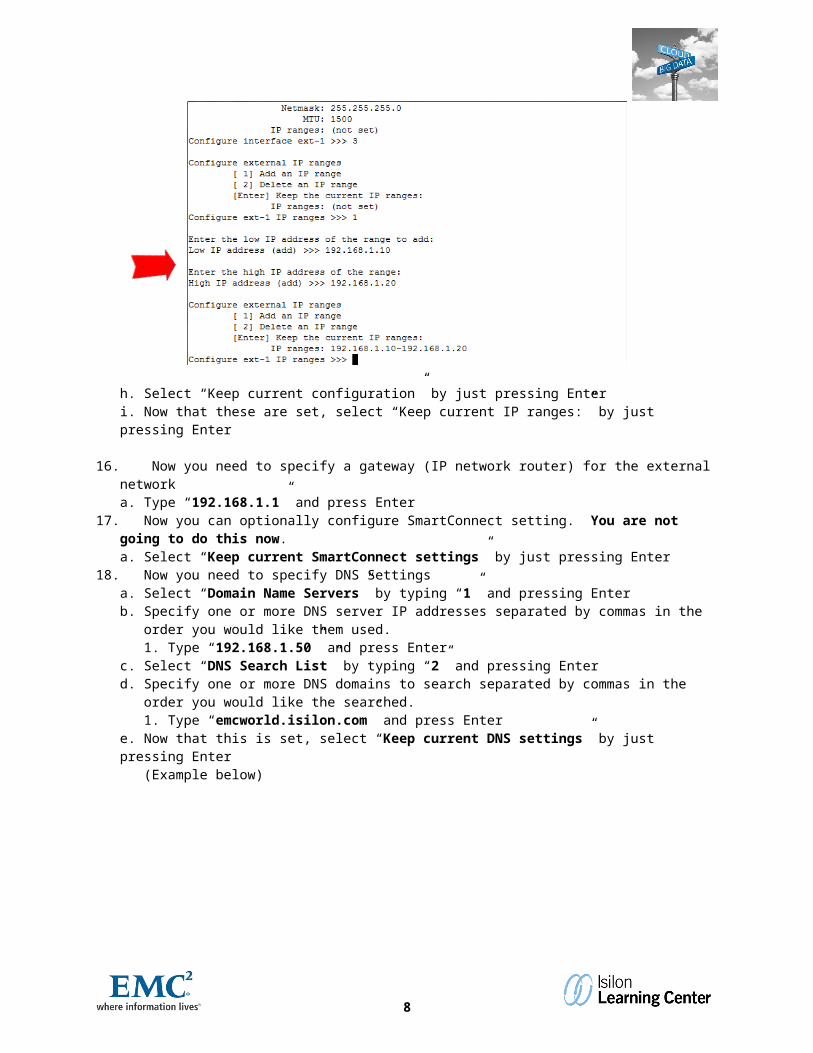
1. Low IP address: Type “192.168.1.10” and press Enter2. High IP address: Type “192.168.1.20” and press EnterExample: 192.168.1.10 ~ 192.168.1.20
h. Select “Keep current configuration” by just pressing Enteri. Now that these are set, select “Keep current IP ranges:” by just pressing Enter
16. Now you need to specify a gateway (IP network router) for the external networka. Type “192.168.1.1” and press Enter
17. Now you can optionally configure SmartConnect setting. You are not going to do this now.a. Select “Keep current SmartConnect settings” by just pressing Enter
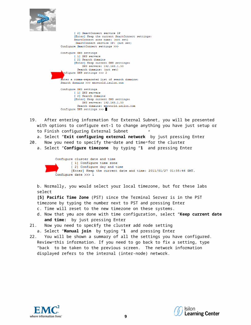
18. Now you need to specify DNS Settingsa. Select “Domain Name Servers” by typing “1” and pressing Enterb. Specify one or more DNS server IP addresses separated by commas in the order you would like them used.
1. Type “192.168.1.50” and press Enterc. Select “DNS Search List” by typing “2” and pressing Enterd. Specify one or more DNS domains to search separated by commas in the order you would like the
searched.1. Type “emcworld.isilon.com” and press Enter
e. Now that this is set, select “Keep current DNS settings” by just pressing Enter (Example below)
7
19. After entering information for External Subnet, you will be presented with options to configure ext-1 to change anything you have just setup or to Finish configuring External Subneta. Select “Exit configuring external network” by just pressing Enter
20. Now you need to specify the date and time for the clustera. Select “Configure timezone” by typing “1” and pressing Enter
b. Normally, you would select your local timezone, but for these labs select [5] Pacific Time Zone (PST) since the Terminal Server is in the PST timezone by typing the number next to PST and pressing Enterc. Time will reset to the new timezone on these systems.d. Now that you are done with time configuration, select “Keep current date and time:” by just pressing
Enter 21. Now you need to specify the cluster add node setting
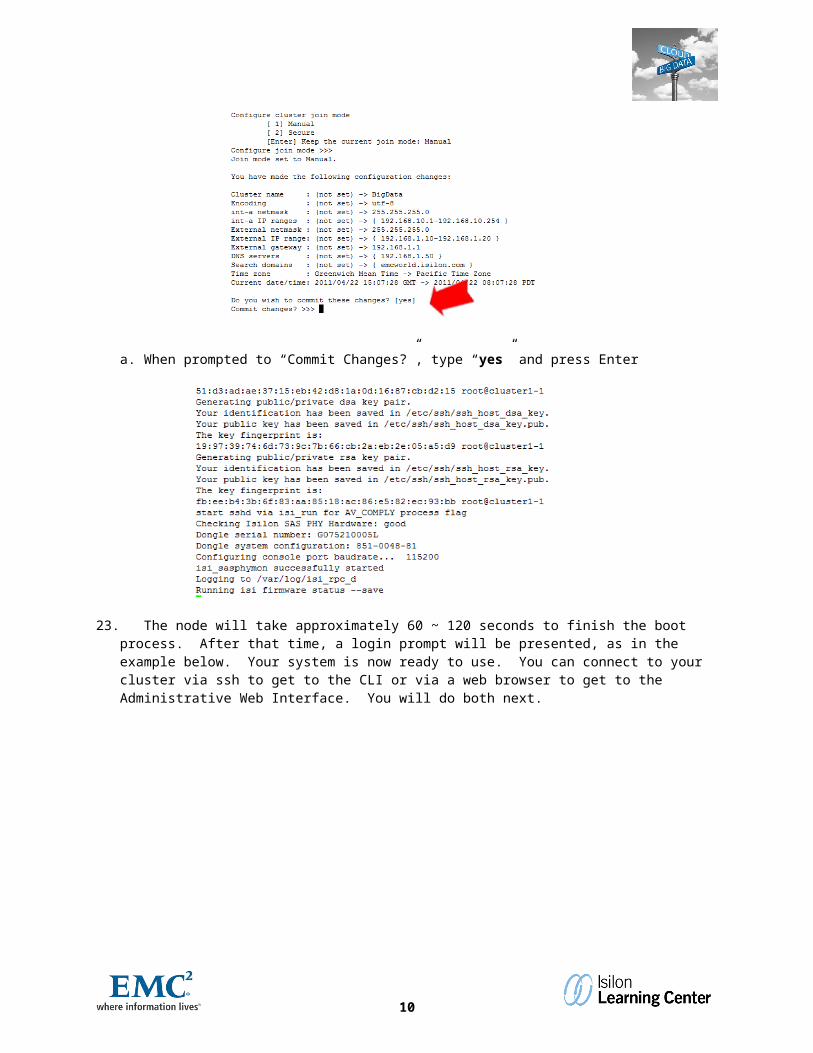
a. Select “Manual join” by typing “1” and pressing Enter22. You will be shown a summary of all the settings you have configured. Review this information. If you need to
go back to fix a setting, type “back” to be taken to the previous screen. The network information displayed refers to the internal (inter-node) network.
8
a. When prompted to “Commit Changes?”, type “yes” and press Enter
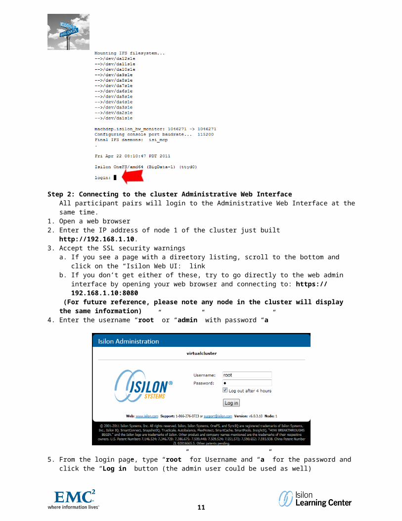
23. The node will take approximately 60 ~ 120 seconds to finish the boot process. After that time, a login prompt will be presented, as in the example below. Your system is now ready to use. You can connect to your cluster via ssh to get to the CLI or via a web browser to get to the Administrative Web Interface. You will do both next.
Step 2: Connecting to the cluster Administrative Web InterfaceAll participant pairs will login to the Administrative Web Interface at the same time.
1. Open a web browser 2. Enter the IP address of node 1 of the cluster just built http://192.168.1.10.3. Accept the SSL security warnings
a. If you see a page with a directory listing, scroll to the bottom and click on the “Isilon Web UI:” linkb. If you don’t get either of these, try to go directly to the web admin interface by opening your web browser
and connecting to: https:// 192.168.1.10:8080 (For future reference, please note any node in the cluster will display the same information)
4. Enter the username “root” or “admin” with password “a”
9
5. From the login page, type “root” for Username and “a” for the password and click the “Log in” button (the admin user could be used as well)
6. Once logged in, you will be taken to the “Cluster Status” screen7. Verify that the node you configured is healthy and has the correct IP address displayed.
Step 3: Connecting to the cluster command lineAll participant pairs will login to the command line at the same time. 1. Open a standard ssh connection
a. If using some other Unix / Linux shell system # ssh 192.168.1.10i. Using putty (Windows)
ii. Host Name (or IP address): 192.168.1.10Port (leave as the standard 22)
iii. Connection type: SSHb. Login using the root account and the password you set earlier in the lab (step 1 item 5)
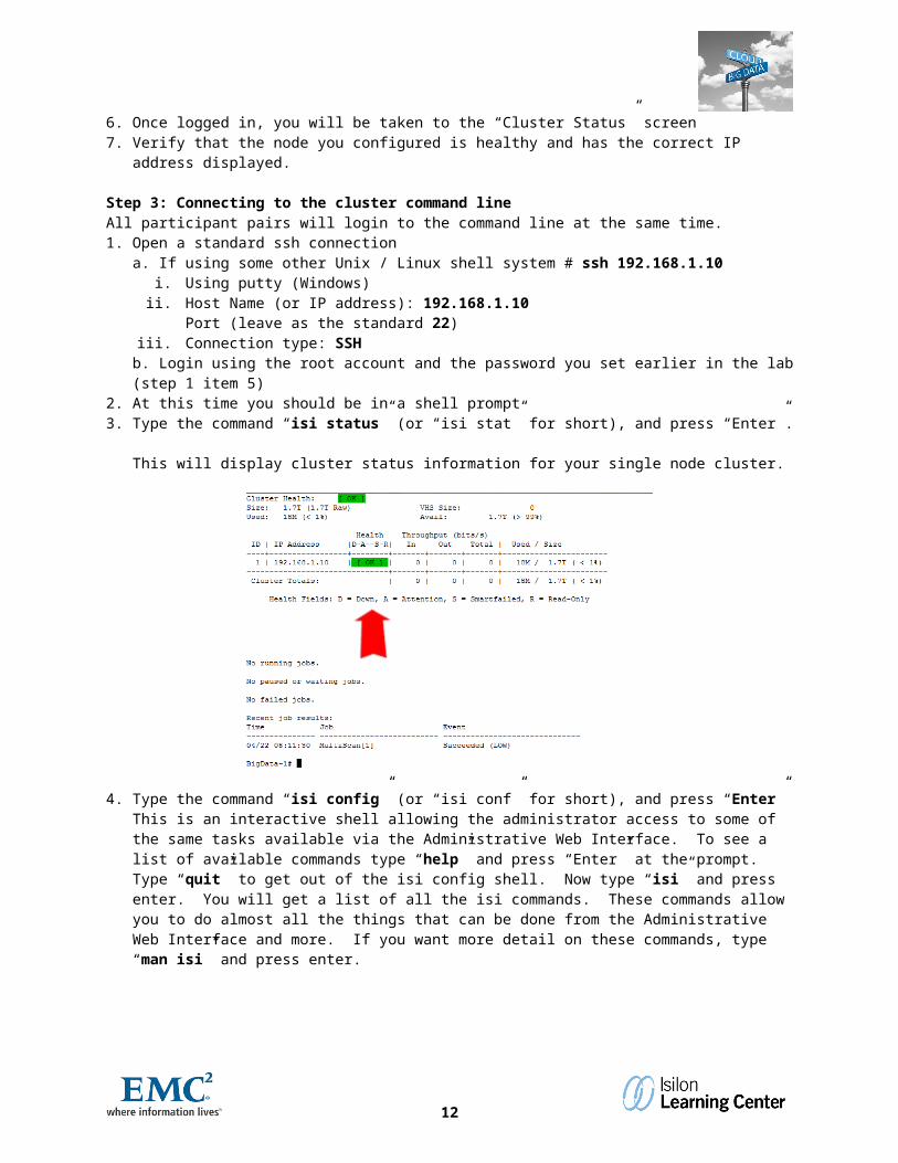
2. At this time you should be in a shell prompt3. Type the command “isi status” (or “isi stat” for short), and press “Enter”.
This will display cluster status information for your single node cluster.
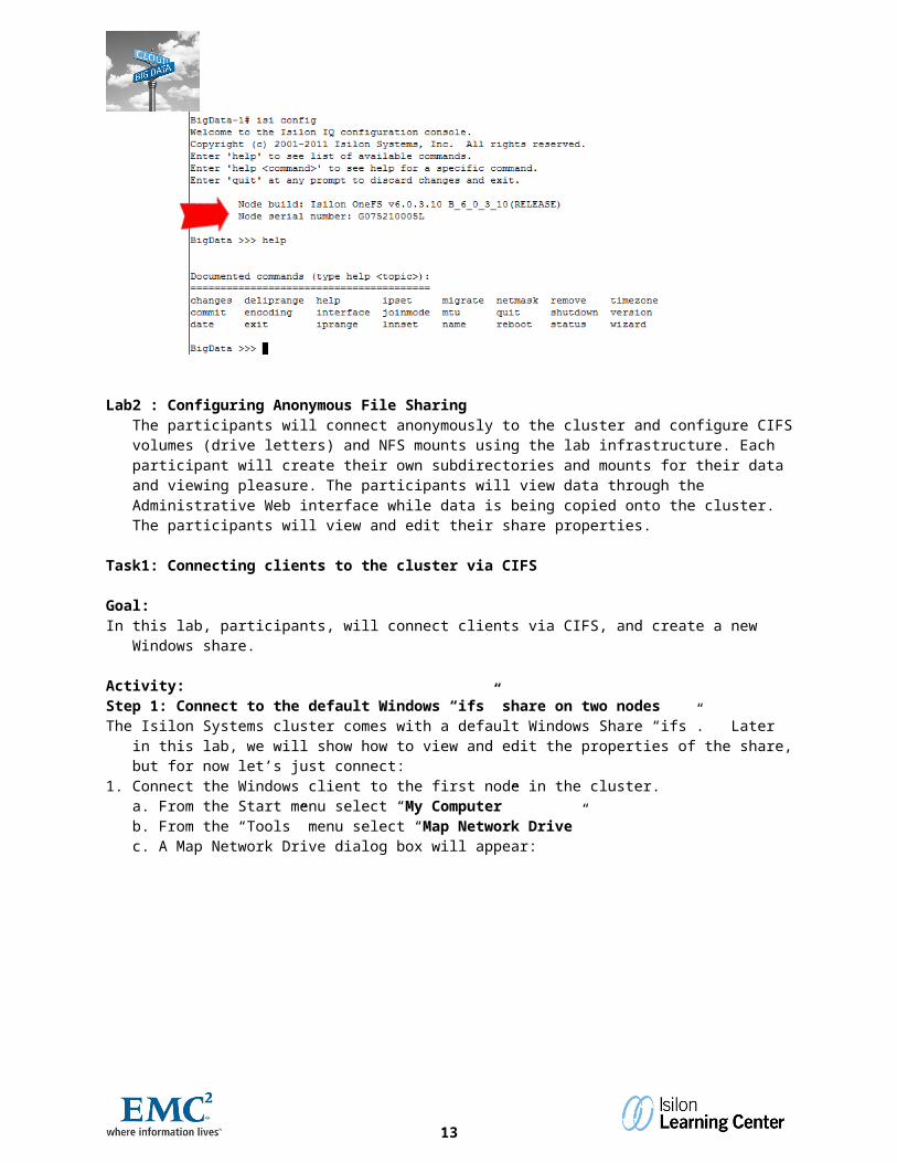
4. Type the command “isi config” (or “isi conf” for short), and press “Enter”This is an interactive shell allowing the administrator access to some of the same tasks available via the Administrative Web Interface. To see a list of available commands type “help” and press “Enter” at the prompt. Type “quit” to get out of the isi config shell. Now type “isi” and press enter. You will get a list of all
10
the isi commands. These commands allow you to do almost all the things that can be done from the Administrative Web Interface and more. If you want more detail on these commands, type “man isi” and press enter.
Lab2 : Configuring Anonymous File SharingThe participants will connect anonymously to the cluster and configure CIFS volumes (drive letters) and NFS mounts using the lab infrastructure. Each participant will create their own subdirectories and mounts for their data and viewing pleasure. The participants will view data through the Administrative Web interface while data is being copied onto the cluster. The participants will view and edit their share properties.
Task1: Connecting clients to the cluster via CIFS
Goal:In this lab, participants, will connect clients via CIFS, and create a new Windows share.
Activity:Step 1: Connect to the default Windows “ifs” share on two nodesThe Isilon Systems cluster comes with a default Windows Share “ifs”. Later in this lab, we will show how to view
and edit the properties of the share, but for now let’s just connect:1. Connect the Windows client to the first node in the cluster.
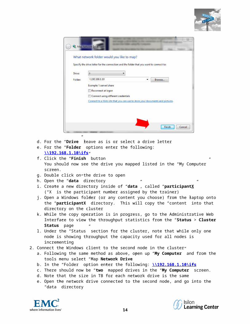
a. From the Start menu select “My Computer”b. From the “Tools” menu select “Map Network Drive”c. A Map Network Drive dialog box will appear:
11
d. For the “Drive” leave as is or select a drive lettere. For the “Folder” options enter the following:
\\192.168.1.10\ifs f. Click the “Finish” button
You should now see the drive you mapped listed in the “My Computer” screen. g. Double click on the drive to openh. Open the “data” directoryi. Create a new directory inside of “data”, called “participantX” (“X” is the
participant number assigned by the trainer)j. Open a Windows folder (or any content you choose) from the laptop onto the “participantX” directory.
This will copy the “content” into that directory on the clusterk. While the copy operation is in progress, go to the Administrative Web Interface to view the throughput
statistics from the “Status > Cluster Status” pagel. Under the “Status” section for the cluster, note that while only one node is showing throughput the capacity
used for all nodes is incrementing2. Connect the Windows client to the second node in the cluster
a. Following the same method as above, open up “My Computer” and from the tools menu select “Map Network Drive”
b. In the “Folder” option enter the following: \\192.168.1.10\ifs c. There should now be “two” mapped drives in the “My Computer” screen.d. Note that the size in TB for each network drive is the samee. Open the network drive connected to the second node, and go into the “data” directory
Step 2: Viewing the properties of a Windows share, creating a new one and mapping the new share1. To view the properties of a share in the Administrative Web Interface
a. Login to the Administrative Web Interface as root or adminb. In the drop down menu select File Sharing > CIFS - Windows File Sharing > Sharesc. Now there should be a listing of all available Windows Shares
i. Click on the “Edit” link next to ifs2. To create a new share
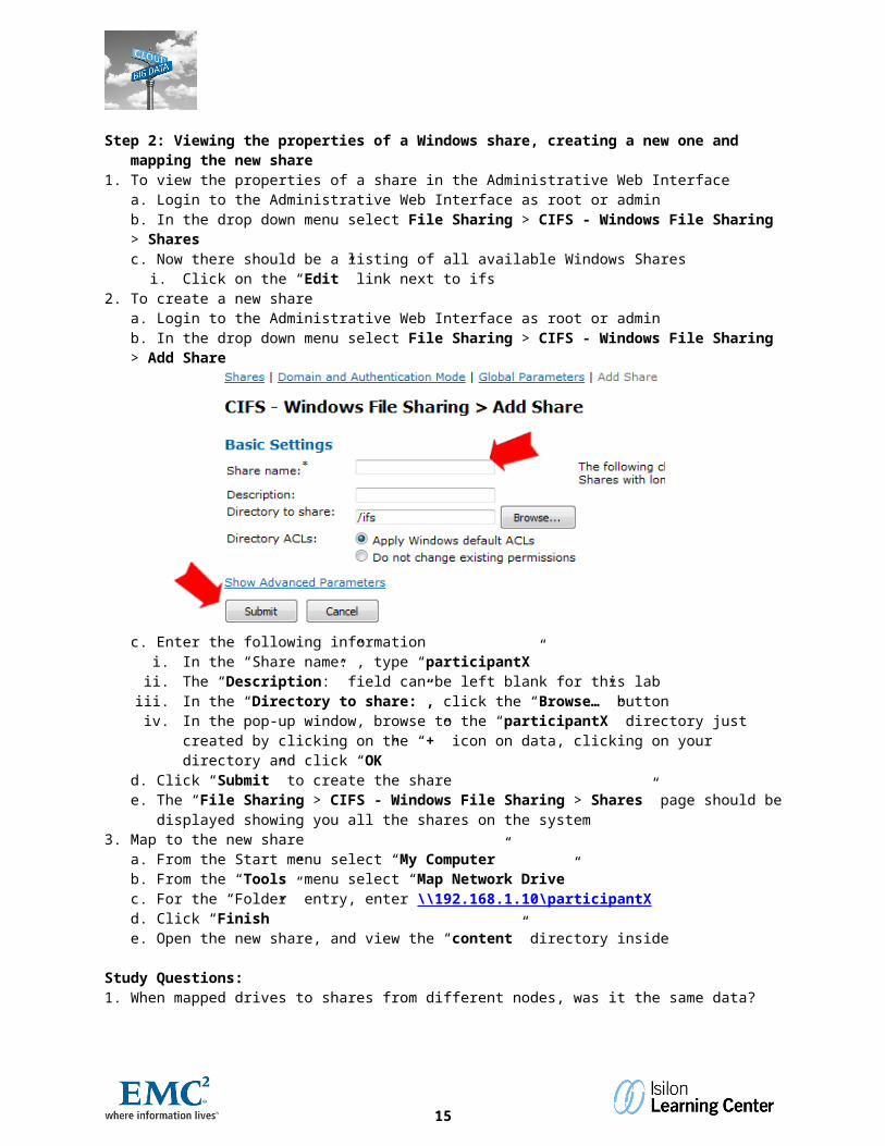
a. Login to the Administrative Web Interface as root or adminb. In the drop down menu select File Sharing > CIFS - Windows File Sharing > Add Share
12
c. Enter the following informationi. In the “Share name:”, type “participantX”
ii. The “Description:” field can be left blank for this labiii. In the “Directory to share:”, click the “Browse…” buttoniv. In the pop-up window, browse to the “participantX” directory just created by clicking on the “+” icon
on data, clicking on your directory and click “OK”d. Click “Submit” to create the sharee. The “File Sharing > CIFS - Windows File Sharing > Shares” page should be displayed showing you all
the shares on the system3. Map to the new share
a. From the Start menu select “My Computer”b. From the “Tools” menu select “Map Network Drive”c. For the “Folder” entry, enter \\192.168.1.10\participantXd. Click “Finish”e. Open the new share, and view the “content” directory inside
Study Questions:1. When mapped drives to shares from different nodes, was it the same data?2. Was the end user experience affected by using the cluster vs. a standard Windows Server share?
13
OneFS : How Big Data is Done!
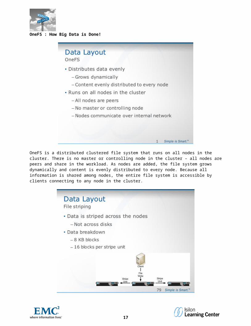
OneFS is a distributed clustered file system that runs on all nodes in the cluster. There is no master or controlling node in the cluster – all nodes are peers and share in the workload. As nodes are added, the file system grows dynamically and content is evenly distributed to every node. Because all information is shared among nodes, the entire file system is accessible by clients connecting to any node in the cluster.
OneFS stripes data across nodes and disks. During a write, the system breaks data into smaller logical sections called stripes and then logically places the data in a stripe unit. As the system lays data across the cluster, it fills the
14
stripe units until the maximum width of the cluster is reached. Each OneFS block is 8 KB, and a stripe unit consists of 16 blocks, for a total of 128 KB per stripe unit.
OneFS uses advanced data layout algorithms to determine data layout for maximum efficiency and performance. Data is evenly distributed across nodes as it is written. The system can continuously reallocate data and make storage space more usable and efficient. Depending on the file size and the stripe width (determined by the number of nodes), as the cluster size increases, the system stores large files more efficiently.
OneFS protects stripes with either parity, also known as error correction code (ECC), or mirroring. The process of creating parity starts breaking a file down into chunks, then a value is calculated for each chunk. The value of the chunks is then added together and the sum of those values is the parity value.The steps to this are as follows:Step 1 - Files are broken into smaller sections called stripesStep 2 - Stripes are broken into even smaller pieces called chunks. A parity chunk is calculatedStep 3 - Each chunk including the parity chunk is then written to a separate device (for Raid5 a HD for Isilon a
Node)Step 4 - If a hard drive is lost what happens?
15

Step 5 - The values of the remaining data are gathered.Step 6 - The missing value is calculated, which is the parity value minus the remaining data values.Step 7 - The calculated values are used to make recreate the missing stripes.Step 8 - Stripes are recombined to make the file without any action or even the knowledge of the end user.
The Isilon clustered storage system provides a proprietary system called FlexProtect, which detects and repairs files and directories that are in a degraded state. Isilon FlexProtect protects data in the cluster, rebuilding failed disks in the event of a failure, using free storage space across the entire cluster to further prevent data loss, and monitoring and preemptively migrating data off of at-risk components.
16
FlexProtect distributes all data and error-correction information across the entire Isilon cluster and ensures that all data remains intact and accessible even in the event of simultaneous component failures. Protection settings can be changed without taking the cluster or file system offline. Protection is applied at the file not the block level and OneFS allow different protection level on directories.
OneFS supports N+1, N+2:1, N+2, N+3:1, N+3, and N+4 data protection schemes, and up to 8x mirroring. For most nodes, the default protection policy is N+1, which means that one drive, multiple drives within a node, or an entire node can fail without causing any data loss. Optionally, you can enable N+2, N+3, or N+4 protection, which allows the cluster to sustain two, three, or four simultaneous failures without causing data loss.
The default protection setting for the cluster is +2:1. Isilon provides recommendations on when to move to a higher protection level based on the quantity and type of nodes.
17