Embed Size (px)
Citation preview

EMC Training
Ing Angelo Cereser
Mobile: 335 57 88 293
Dott Mirko Bombelli
Mobile: 335 12 36 792

Agenda
Introduzione alle misure EMI Terminologia; precompliance verso full compliance
Setup di misura: emissioni radiate e condotte
CISPR 16-1-1 & MIL461F (Cenni)
L’analizzatore di spettro per le misure EMI
Time Scan mode Differenti metodi di scansione ( swept, stepped, time domain )
Approccio veloce al precompliance
Real Time Analysis Definizione di Real Time , Real Time operation , Overlap processing

Agenda
Introduzione alle misure EMI Terminologia; precompliance verso full compliance
Setup di misura: emissione radiate e condotte
CISPR 16-1-1 & MIL461F (Cenni)
L’analizzatore di spettro per le misure EMI
Time Scan mode Differenti metodi di scansione ( swept, stepped, time domain )
Approccio veloce al precompliance
Real Time Analysis Definizione di Real Time , Real Time operation , Overlap processing
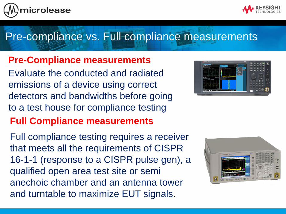
Pre-compliance vs. Full compliance measurements
Pre-Compliance measurements
Evaluate the conducted and radiated
emissions of a device using correct
detectors and bandwidths before going
to a test house for compliance testing
Full Compliance measurements
Full compliance testing requires a receiver
that meets all the requirements of CISPR
16-1-1 (response to a CISPR pulse gen), a
qualified open area test site or semi
anechoic chamber and an antenna tower
and turntable to maximize EUT signals.
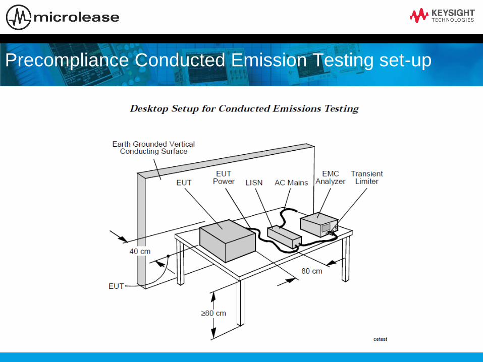
Precompliance Conducted Emission Testing set-up

Precompliance Radiated Emission Testing set-up

Compliance EMI receiver requirements
A CISPR 16-1-1 receiver must have the following functionality in the
range 9 kHz - 18 GHz:
A normal +/- 2 dB absolute accuracy
CISPR-specified resolution bandwidths (-6 dB)
Peak, quasi-peak, EMI average, and RMS average detectors
Specified input impedance with a nominal value of 50 ohms;
deviations specified as VSWR
Be able to pass product immunity in a 3 V/m field
Be able to pass the CISPR pulse test (implies pre-selector below 1
GHz)
Other specific harmonic and intermodulation requirements

Receiver requirements above 1 GHz
1 MHz bandwidth for measurements
No quasi-peak detector
No CISPR pulse test, meaning no additional pre-selector required
excellent sensitivity
According to current FCC regulations, the maximum test frequency
is the fifth harmonic of the highest clock frequency for an
“unintentional radiator” (for example, computers without wireless
connectivity) and the tenth harmonic for an intentional radiator (such
as a cellular phone or wireless LAN).

MIL STD 461F
• Spectrum Analyzer use allowed (and commonly used)
- need to ensure measurement linearity (avoid overloads)
- need to have sufficient sensitivity (may need preamp)
• Requires MIL Bandwidths
• Requires Peak Detector
• +/- 2dB amp accuracy, +/- 2% frequency accuracy
• Dwell times specified in document

Agenda
Introduzione alle misure EMI Terminologia; precompliance verso full compliance
Setup di misura: emissione radiate e condotte
CISPR 16-1-1 & MIL461F (Cenni)
L’analizzatore di spettro per le misure EMI
Time Scan mode Differenti metodi di scansione ( swept, stepped, time domain )
Approccio veloce al precompliance
Real Time Analysis Definizione di Real Time , Real Time operation , Overlap processing

Theory of Operation
• Swept Spectrum Analyzer Block Diagram
Pre-Selector
Or Low Pass
Input Filter
Crystal
Reference
Oscillator
Log
Amp
RF input
attenuator mixer
IF filter
(RBW)envelope
detector
video
filterlocal
oscillator
sweep
generator
IF gain
Input
signal
ADC,
Display &
Video
Processing

RF Section ADC
IF/BB Section
on ASIC
Flexibility:
RBW filtering in 10% steps
Filters with better selectivity
Multiple operation modes (Swept, FFT, VSA, NFA)
Accuracy:
Log conversion practically ideal
No drift errors; increased repeatability
Speed:
When Swept mode is slow, go FFT
FFT
All Digital IF” Advantages

Digital IF Improves Amplitude Accuracy
Input
Connector
Down-
conversionIF
Gain
IF
FilterLog
Amp
Video
Filter
RF Input
Attenuator2 dB Steps
Pre-selector
Log ADC
ADC DSP
Digital IF improves Amplitude Accuracy:
• Ref Level switching uncertainty (IF gain)
− Level correction digitally synthesized
• RBW filter switching uncertainty
− RBWs all digitally synthesized
• Display scale fidelity (Log Amp)
− Log response & display scaling digitally synthesized
Frequency
DependentFrequency
Independent
Amplitude
Uncertainty
N9038A
Receiver
Analog IF
(older
receivers)
Ref Level
Switching0dB <= +/- 1dB
RBW
Switching+/- .05dB <= +/- .5dB
Display Scale
Fidelity+/- .15dB <= +/- .85dB

EMI Receiver Block Diagram ( Keysight MXE )
Input 1
Input 2
Attenuation
Transient
Limiter
RF Preselector
Analog IF
Filter
Pre-amp
ADC
Digital IF
Filter
Digital Log Amp
Digital Detectors
FFT
Swept vs. FFT
MXE

RF Pre-selection (RF input filtering)
Purpose of RF pre-selection
– Help to prevent overload by reducing total energy at input mixer
– RF preselector tracks the center frequency of the EMI receiver
– The bandwidth of the RF preselector is wider than the widest RBW used
Useful in measuring broadband signals
Types of filters used in RF pre-selectors
– Low-pass, Band-pass and High-pass
– Fixed and Tracking
Broadband
signals
Narrow
band
signals

Wider RF Preselector Filter BW = Reduced Impulse Overload Protection
• Examples* : @10MHz: 20 log (35MHz/9.5MHz) = 11.3dB
• @ 500MHz: 20 log (200MHz/ 50MHz) = 12dB
• *Note: Above calculations using 6dB BW ratios, not impulse BW ratios
• Results provide approximate values of required input attenuation
Down-
conversion
RF
Preselector
Receiver RF Section
Vp
Impulse BW
BWi
Τ= pulse
width
Vmax = Vp Τ BWi
Input pulse
Max Pulse voltage
into mixer is
proportional
to RFPS filter
impulse BW (BWi)RF Input
Attenuator

RF Preselector Bands for MXE
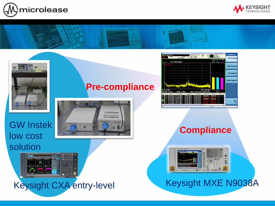
Pre-compliance
Compliance
N6141A EMI Measurement Application
GW Instek
low cost
solution
Keysight CXA entry-level Keysight MXE N9038A
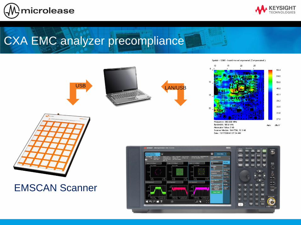
CXA EMC analyzer precompliance
USB LAN/USB
EMSCAN Scanner
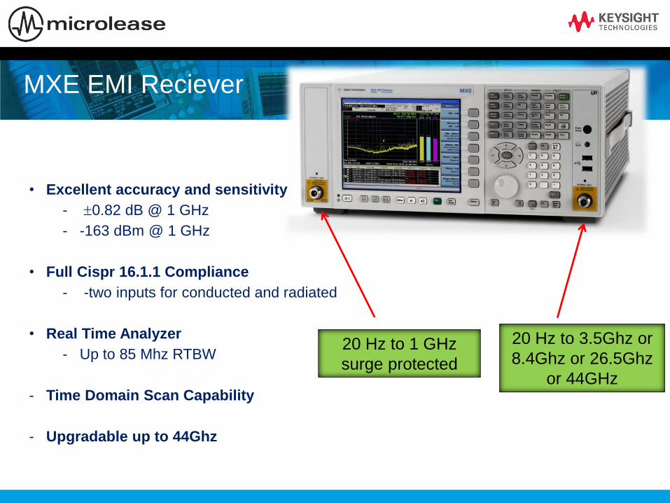
MXE EMI Reciever
• Excellent accuracy and sensitivity
- 0.82 dB @ 1 GHz
- -163 dBm @ 1 GHz
• Full Cispr 16.1.1 Compliance
- -two inputs for conducted and radiated
• Real Time Analyzer
- Up to 85 Mhz RTBW
- Time Domain Scan Capability
- Upgradable up to 44Ghz
20 Hz to 3.5Ghz or
8.4Ghz or 26.5Ghz
or 44GHz
20 Hz to 1 GHz
surge protected
Agenda
Introduzione alle misure EMI Terminologia; precompliance verso full compliance
Setup di misura: emissione radiate e condotte
CISPR 16-1-1 & MIL461F (Cenni)
L’analizzatore di spettro per le misure EMI
Time Scan mode Differenti metodi di scansione ( swept, stepped, time domain )
Approccio veloce al precompliance
Real Time Analysis Definizione di Real Time , Real Time operation , Overlap processing

Customer challenge
• Need for SPEED
– DUTs that require short measurement time (ex. motor starter)
– Test MORE devices
– Shorter turn-around-time
• Depends On:
– Scan type (Stepped, Swept, Time Domain)
– Resolution Bandwidth
– Dwell Time
– RF Preselector
– Other?

Methods to EMI Scanning
• Stepped Scan
– Slowest method
– LO moves for every bin
– Must re-tune LO each time
• Swept Scan
– Slow (slightly faster than Stepped)
– LO re-tunes once each sweep
• Time Domain Scan (TDS)
– Very fast
– Highly overlapped FFT (>90%)
– Alternate scan method allowed by CISPR 16

Time Domain Scan (TDS)
• What is “Time Domain Scan”- A new way to do Frequency scanning
- Swept scans, Stepped scans, now Time Domain scans
• FFT-based scan
- uses ~ 90% overlap (in time) to ensure amplitude accuracy
for measurements of both CW and Impulsive signals
•Allowed by CISPR 16, but not required.
- Internal Automotive industry testing specifications require
Time Domain
33

How Time Domain Sweep Saves Time
frequency
am
plit
ude
frequency
am
plit
ude
Receiver FFT BWReceiver Resolution BW
Swept or Stepped
Frequency Scan
Time Domain
Frequency Scan
Have to dwell at
each RBW
Only have to dwell for each
FFT BW (multiple RBWs)FFT BW
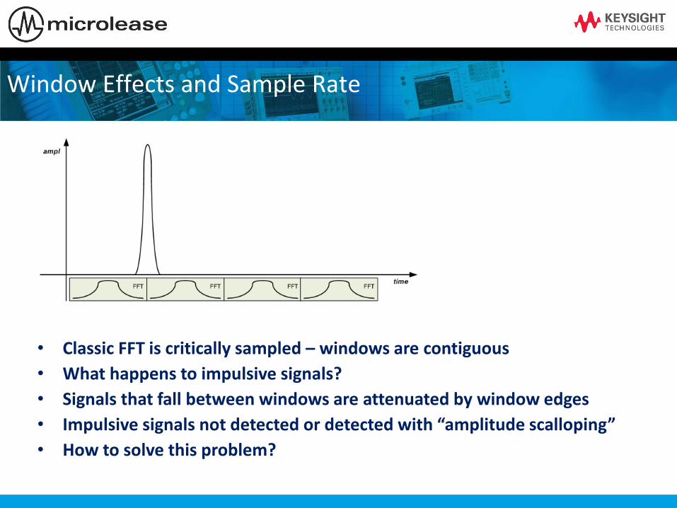
• Classic FFT is critically sampled – windows are contiguous
• What happens to impulsive signals?
• Signals that fall between windows are attenuated by window edges
• Impulsive signals not detected or detected with “amplitude scalloping”
• How to solve this problem?
Window Effects and Sample Rate
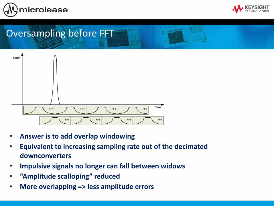
• Answer is to add overlap windowing
• Equivalent to increasing sampling rate out of the decimated downconverters
• Impulsive signals no longer can fall between widows
• “Amplitude scalloping” reduced
• More overlapping => less amplitude errors
Oversampling before FFT

Time
Domain
Scan
Frequency
Domain Scan
CISPR Band MXE MXE
30MHz–1GHzPeak det. 10ms. dwell
RBW =120kHz
3 pts/RBW~ 12 s 242 sec
smooth scan
150kHz–30 MHzPeak det 100ms. dwell
RBW = 9kHz
2 pts/RBW~ 13 s 664 sec
smooth scan
Time Domain improves sweep time
Page 37

Agenda
Introduzione alle misure EMI Terminologia; precompliance verso full compliance
Setup di misura: emissione radiate e condotte
CISPR 16-1-1 & MIL461F (Cenni)
L’analizzatore di spettro per le misure EMI
Time Scan mode Differenti metodi di scansione ( swept, stepped, time domain )
Approccio veloce al precompliance
Real Time Analysis Definizione di Real Time , Real Time operation , Overlap processing
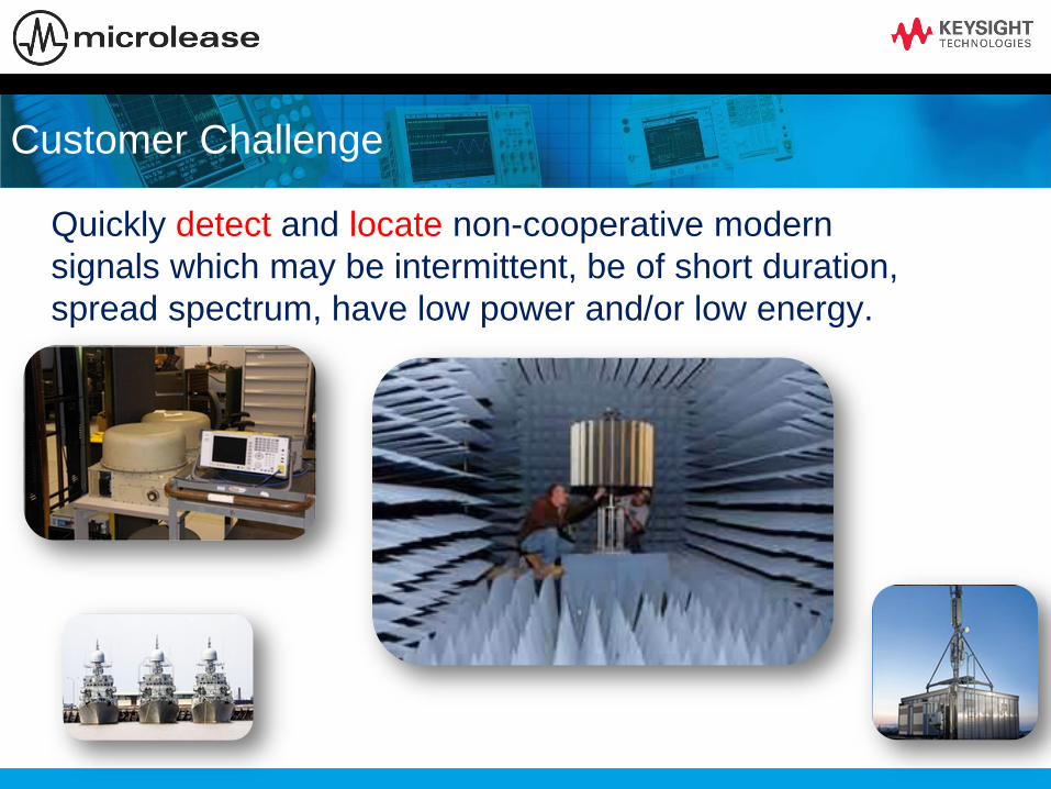
Customer Challenge
Quickly detect and locate non-cooperative modern
signals which may be intermittent, be of short duration,
spread spectrum, have low power and/or low energy.

What is “Real Time” Analysis?
•General Definition of Real Time
– Measurement operations where all signal samples are used in calculating
measurement results of some kind (usually spectrum)
•Real Time Bandwidth (RTBW)
– The widest analysis bandwidth where an analyzer can maintain real time
operation
– Duration of maintaining real time operation is not specified; it may assumed to
be short term or long term or unlimited
•Current Usage for Signal Analyzers
– A spectrum or FFT analyzer having a signal processing path where most or all
samples, even at wide bandwidths, are used to create a spectral display or to
trigger signal measurement or acquisition (sometimes both)
What is Real Time?
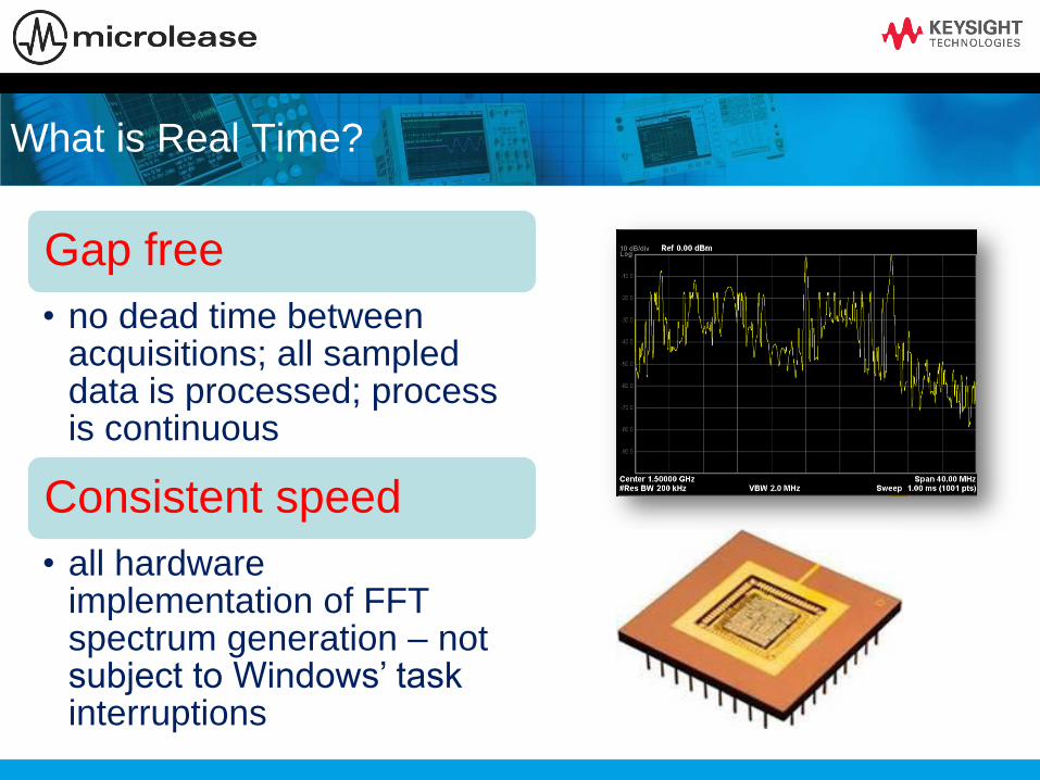
Gap free
• no dead time between acquisitions; all sampled data is processed; process is continuous
Consistent speed
• all hardware implementation of FFT spectrum generation – not subject to Windows’ task interruptions

What is Real Time?
High speed measurements
• many thousands of FFT generated spectrums per second, vastly exceeding software FFT speed
High speed displays
• combine large numbers of measurements to form responsive, insight-producing displays

Real Time Operation
•In Real Time Operation the Analyzer’s Processing (CALC) is
Fast Enough to Keep Up with All Data Samples
•CALC Time Includes FFT or Power Spectrum, Averaging, Display
Updates, etc.
However some data
may still be “lost”

Overlap Processing
•If Processing is Faster than Sampling, Perform Additional FFTs With Partially-New
Time Records as Samples Come In
Avoid Loss of Data Due to Windowing
Accurate Amplitude Measurements of Short Duration Signals
Overlap 0%
Overlap 50% Processor Idle
Window
Function

Swept tuned spectrum analyzer
Pros:
- Excellent dynamic range
- Very fast sweep for very large span
- Precisely control sweep time
- Easy to measure line spectrum of pulse
signal
-
Cons:
- Could miss intermittent signal contents
- Very slow when RBW:SPAN is too small
-

Snap shot FFT spectrum analyzer
filterattn IF A/D FFT
mixer
LO Sample scheduler
Pros:
- Not missing signal content within
information bandwidth
- Very fast update at narrow RBW
- Provides digital demodulation
Cons:
- Relative slow under very large bandwidth
- Cannot precisely control sweep time
- When signal is larger than its instantaneous
bandwidth, stitching is required (could miss
change of signals)
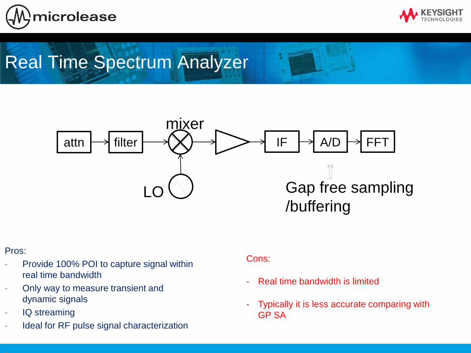
Real Time Spectrum Analyzer
filterattn IF A/D FFT
mixer
LO Gap free sampling
/buffering
Pros:
- Provide 100% POI to capture signal within
real time bandwidth
- Only way to measure transient and
dynamic signals
- IQ streaming
- Ideal for RF pulse signal characterization
-
Cons:
- Real time bandwidth is limited
- Typically it is less accurate comparing with
GP SA

Probability of missing signals
Real time BW
Freq
Time
Swept tuned SA Snapshot FFT SA Real time SA


RTSA applications
In traditional SA mode, it is hard to
find the interfering signal buried
inside downlink carrier.
The narrow band signal (center:
877MHz, bandwidth:12 kHz )
In RTSA, density display can clearly
identify the embedded signal at
877MHz
Embedded signal

RTSA Enhancements
Available on Xseries
• Enabled in both FMT and Level Triggers
• Trigger only on signals that are less than,
greater than, inside, or outside defined time
durations
Interfering Zigbee and
WLAN - Overlapping
signals in the frequency
domain can be resolved
by using TQT
Isolated WLAN
signal
Isolated Zigbee

Summary
3.57 us Probability of Intercept
• Best performance for measuring intermittent signals
Widest BW & Freq
• 85 MHz bandwidth and 44 GHz frequency range to analyze large chunks of the spectrum
Two in one
• Eliminate the need for a specialized or dedicated instrument by adding real-time capabilities to the MXE EMI Reciever

Per documentazione su prodotti ed applicazioni EMI/EMC visitare il sito
http://www.keysight.com/find/EMC
THANK YOU!!