Embed Size (px)
Citation preview
AdvAnced MAteriAls – the Key to Progress
EMC PRODUCTS b a S E D O n n a n O C R Y S T a L L I n E V I T R O P E R M
2 nAnocrystAlline vitroPerM / eMc Products
the coMPAny VaCUUMSCHMELZE
Contents
Introduction Page 3
Superior EMC filter- and common mode choke design Page 5
VITROPERM vs. ferrite Page 7
Properties of VITROPERM Page 8
Design advantages Page 12
Standard series VITROPERM cores Page 14
Core stacks Page 18
Common mode chokes (standard UL1446) Page 20
Further design support Page 24
Common mode choke design checklist Page 26
We are a global company with our headquarters in Hanau, Germany. We currently have approximately 4300 employees who are spread over production and sales locations in more than 50 countries on every continent generating annual sales of approximately EUR 380 million.
VACUUMSCHMELZE GmbH & Co. KG (VAC) is a leading global manufacturer of modern magnetic alloys, cores and inductive components. VAC has supplied innovative solutions for electromagnetic compatibility (EMC) protection for more than 30 years.
3NaNocrystalliNe Vitroperm / emc products
Nowadays power electronics have a decisive influence on the technology of electrical energy generation, distribution and conversion. Modern semiconductors enable electrical energy to be controlled and converted rapidly and safely with low losses. However, using today’s fast switching technologies results in significant network disturbances. To minimize these disturbances and stabilizing electric networks, EMI filters according to latest international standards must be used. VAC’s VITROPERM® EMC products make a significant contribution in building innovative and compact filter designs with lowest losses.
Our EMC products are used in a wide range of applications:
• switched-mode power supplies (sMPs)
• solar inverters
• Frequency converters
• eMc filters
• Welding equipment
• Wind generators
• induction hobs
• Automotive applications
• uninterruptible power supplies (uPs)
EMC PRODUCTS b a S E D O n n a n O C R Y S T a L L I n E V I T R O P E R M
® = registered trademark of VACUUMSCHMELZE GmbH & Co. KG
4 NaNocrystalliNe Vitroperm / emc products
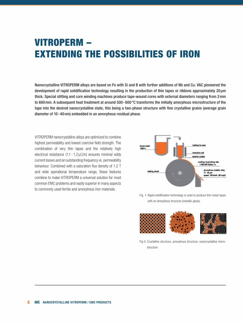
Nanocrystalline VITROPERM alloys are based on Fe with Si and B with further additions of Nb and Cu. VAC pioneered the development of rapid solidification technology resulting in the production of thin tapes or ribbons approximately 20 µm thick. Special slitting and core winding machines produce tape-wound cores with external diameters ranging from 2 mm to 600 mm. A subsequent heat treatment at around 500 - 600 °C transforms the initially amorphous microstructure of the tape into the desired nanocrystalline state, this being a two-phase structure with fine crystalline grains (average grain diameter of 10 - 40 nm) embedded in an amorphous residual phase.
VITROPERM – ExTEnDIng THE POSSIbILITIES Of IROn
VITROPERM nanocrystalline alloys are optimized to combine highest permeability and lowest coercive field strength. The combination of very thin tapes and the relatively high electrical resistance (1.1 - 1.2 µΩm) ensures minimal eddy current losses and an outstanding frequency vs. permeability behaviour. Combined with a saturation flux density of 1.2 T and wide operational temperature range, these features combine to make VITROPERM a universal solution for most common EMC problems and vastly superior in many aspects to commonly used ferrite and amorphous iron materials.
Fig. 1: Rapid solidification technology is used to produce thin metal tapes
with an amorphous structure (metallic glass).
Fig 2: Crystalline structure, amorphous structure, nanocrystalline micro-
structure
5NaNocrystalliNe Vitroperm / emc products
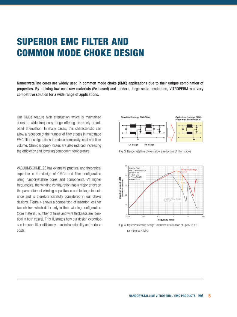
VACUUMSCHMELZE has extensive practical and theoretical expertise in the design of CMCs and filter configuration using nanocrystalline cores and components. At higher frequencies, the winding configuration has a major effect on the parameters of winding capacitance and leakage induct-ance and is therefore carefully considered in our choke designs. Figure 4 shows a comparison of insertion loss for two chokes which differ only in their winding configuration (core material, number of turns and wire thickness are iden-tical in both cases). This illustrates how our design expertise can improve filter efficiency, maximize reliability and reduce costs.
Our CMCs feature high attenuation which is maintained across a wide frequency range offering extremely broad-band attenuation. In many cases, this characteristic can allow a reduction of the number of filter stages in multistage EMC filter configurations to reduce complexity, cost and filter volume. Ohmic (copper) losses are also reduced increasing the efficiency and lowering component temperature. Fig. 3: Nanocrystalline chokes allow a reduction of filter stages
Fig. 4: Optimized choke design: improved attenuation of up to 16 dB
(or more) at 4 MHz
SUPERIOR EMC fILTER anD COMMOn MODE CHOkE DESIgn
Nanocrystalline cores are widely used in common mode choke (CMC) applications due to their unique combination of properties. By utilising low-cost raw materials (Fe-based) and modern, large-scale production, VITROPERM is a very competitive solution for a wide range of applications.
LF Stage HF Stage
Optimized 1-stage EMC-Filter with VITROPERM
Standard 2-stage EMI-Filter
Abb_04_05_06_07_08_09_10_11 en neu 2016.xls [Abb4]J. Beichler [11.03.2016 / 10:39]
0
10
20
30
40
50
0.001 0.01 0.1 1 10 100
inse
rtio
n lo
ss a
E [d
B]
(50
Ohm
sys
tem
)
frequency [MHz]
1-phase CMCcore: VITROPERM 500F25×20×10 mm N = 2x28 turns (0.71 mm/AWG 21)separator: 5 mm
simple winding design,CW=21 pF
HF optimized design, CW=4 pF
16dB
6 NaNocrystalliNe Vitroperm / emc products
AdvAntAges Preconditions / relevAnt ProPerties
Small size High µ, high BS
Suitable for high currents and/or high voltages High µ, high BS, suitable core geometries
Single stage filter designs possible Excellent broadband attenuation behaviour, high permeability, low-capacitance design, moderate reduction of µ up to high frequencies, low Q factor in 150 kHz range
High efficiency, low power loss Low number of turns required for high L, reduction of filter stages
‘Green’, environmentally friendly Low power loss, reduced use of material
Suitable for high and low ambient temperatures and high operating temperatures
High Curie temperature, material properties (µ, BS, s) nearly independent of temperature
‘Easy filter design’ Material properties (µ, BS, s) nearly independent of temperature, linear magnetization curve delivers stable impedance across a broad range of common mode currents – VAC choke design software available
UL-compliant designs Suitable plastic materials meet UL1446 insulation requirements
Optimized solutions for a variety of different applications A range of µ levels and VITROPERM alloys available
No operating noise Material is practically magnetostriction-free
Best suited for winding of thick wires Material is practically magnetostriction-free, coatings/casings are resistant against mechanical stress
fEaTURES & bEnEfITS Of VITROPERM nanOCRYSTaLLInE CHOkES
7NaNocrystalliNe Vitroperm / emc products
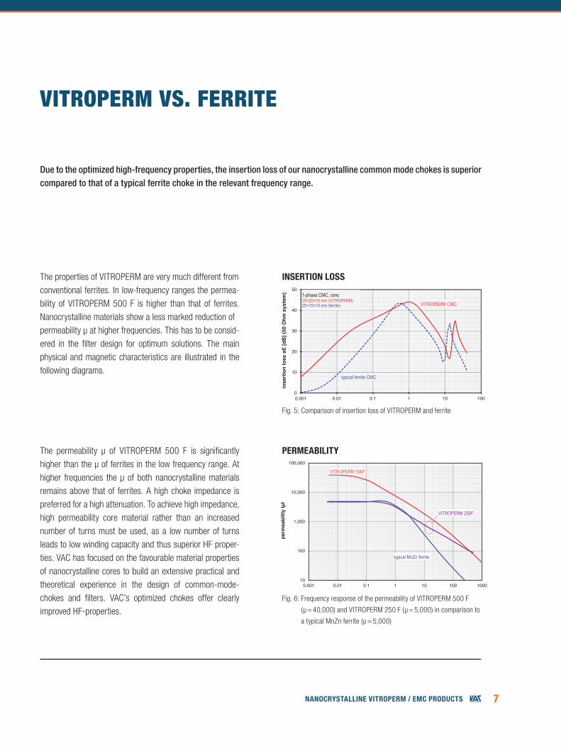
The properties of VITROPERM are very much different fromconventional ferrites. In low-frequency ranges the permea-bility of VITROPERM 500 F is higher than that of ferrites. Nanocrystalline materials show a less marked reduction ofpermeability µ at higher frequencies. This has to be consid-ered in the filter design for optimum solutions. The main physical and magnetic characteristics are illustrated in the following diagrams.
VITROPERM VS. fERRITE
Fig. 5: Comparison of insertion loss of VITROPERM and ferrite
Fig. 6: Frequency response of the permeability of VITROPERM 500 F
(µ = 40,000) and VITROPERM 250 F (µ = 5,000) in comparison to
a typical MnZn ferrite (µ = 5,000)
Due to the optimized high-frequency properties, the insertion loss of our nanocrystalline common mode chokes is superior compared to that of a typical ferrite choke in the relevant frequency range.
Johannes Beichler, KB-EK / Abb_04_05_06_07_08_09_10_11 en neu 2016.xlsAbb6 [Seite: 1]
erstellt: [11.11.1997 / 10:09]Version: [11.03.2016 / 10:41]
10
100
1,000
10,000
100,000
0.001 0.01 0.1 1 10 100 1000
perm
eabi
lity
IµI
frequency [MHz]
VITROPERM 500F
typical MnZn ferrite
VITROPERM 250F
PerMeAbility
insertion loss
Abb_04_05_06_07_08_09_10_11 en neu 2016.xls [Abb 5]J. Beichler [11.03.2016 / 10:40]
0
10
20
30
40
50
0.001 0.01 0.1 1 10 100
inse
rtio
n lo
ss a
E [d
B] (
50 O
hm s
yste
m)
frequency [MHz]
1-phase CMC, core:25×20×10 mm (VITROPERM)25×15×10 mm (ferrite)
typical ferrite CMC
VITROPERM CMC
The permeability µ of VITROPERM 500 F is significantly higher than the µ of ferrites in the low frequency range. At higher frequencies the μ of both nanocrystalline materials remains above that of ferrites. A high choke impedance is preferred for a high attenuation. To achieve high impedance, high permeability core material rather than an increased number of turns must be used, as a low number of turns leads to low winding capacity and thus superior HF proper-ties. VAC has focused on the favourable material properties of nano crystalline cores to build an extensive practical and theoretical experience in the design of common-mode-chokes and filters. VAC’s optimized chokes offer clearly improved HF-properties.
fEaTURES & bEnEfITS Of VITROPERM nanOCRYSTaLLInE CHOkES
8 NaNocrystalliNe Vitroperm / emc products
Johannes Beichler / KB-E BEAbb7 / Abb_04_05_06_07_08_09_10_11 en neu 2016.xls [Seite 1/1]
Erstellt: 08.03.05 / 15:26
100
1,000
10,000
100,000
0.001 0.01 0.1 1 10 100
perm
eabi
lity
µ
frequency [MHz]
µs'
µs''|µ|
VITROPERM 500Fµ=100 000
typical ferriteµ=5 500
µs'µs''
|µ|
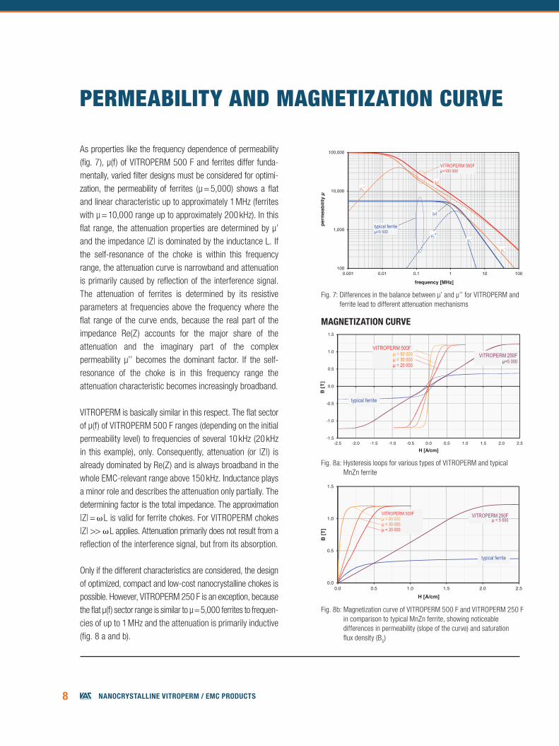
As properties like the frequency dependence of permeability (fig. 7), µ(f) of VITROPERM 500 F and ferrites differ funda-mentally, varied filter designs must be considered for optimi-zation, the permeability of ferrites (μ = 5,000) shows a flat and linear characteristic up to approximately 1 MHz (ferrites with μ = 10,000 range up to approximately 200 kHz). In this flat range, the attenuation properties are determined by μ’ and the impe dance |Z| is dominated by the inductance L. If the self- resonance of the choke is within this frequency range, the attenuation curve is narrowband and attenuation is primarily caused by reflection of the interference signal. The attenuation of ferrites is determined by its resistive para meters at frequencies above the frequency where the flat range of the curve ends, because the real part of the impedance Re(Z) accounts for the major share of the attenuation and the imaginary part of the complex permeability µ’’ becomes the dominant factor. If the self-resonance of the choke is in this frequency range the attenuation character istic becomes increasingly broadband.
VITROPERM is basically similar in this respect. The flat sector of μ(f) of VITROPERM 500 F ranges (depending on the initial permeability level) to frequencies of several 10 kHz (20 kHz in this example), only. Consequently, attenuation (or |Z|) is already dominated by Re(Z) and is always broadband in the whole EMC-relevant range above 150 kHz. Inductance plays a minor role and describes the attenuation only partially. The determining factor is the total impedance. The approximation |Z| = L is valid for ferrite chokes. For VITROPERM chokes |Z| >> L applies. Attenuation primarily does not result from a reflection of the interference signal, but from its absorption.
Only if the different characteristics are considered, the design of optimized, compact and low-cost nanocrystalline chokes is possible. However, VITROPERM 250 F is an exception, because the flat μ(f) sector range is similar to μ = 5,000 ferrites to frequen-cies of up to 1 MHz and the attenuation is primarily inductive (fig. 8 a and b).
PERMEabILITY anD MagnETIZaTIOn CURVE
Fig. 7: Differences in the balance between μ’ and µ’’ for VITROPERM and ferrite lead to different attenuation mechanisms
Fig. 8a: Hysteresis loops for various types of VITROPERM and typical MnZn ferrite
Fig. 8b: Magnetization curve of VITROPERM 500 F and VITROPERM 250 F in comparison to typical MnZn ferrite, showing noticeable differences in permeability (slope of the curve) and saturation flux density (BS)
MAgnetizAtion curve
Abb_04_05_06_07_08_09_10_11 en neu 2016.xls [Abb 8a]J. Beichler [11.03.2016 / 10:42]
-1.5
-1.0
-0.5
0.0
0.5
1.0
1.5
-2.5 -2.0 -1.5 -1.0 -0.5 0.0 0.5 1.0 1.5 2.0 2.5
B [T
]
H [A/cm]
typical ferrite
VITROPERM 500F µ = 80 000µ = 30 000µ = 20 000
VITROPERM 250F µ=5 000
Abb_04_05_06_07_08_09_10_11 en neu 2016.xls [Abb 8b]J. Beichler [11.03.2016 / 10:42]
0.0
0.5
1.0
1.5
0.0 0.5 1.0 1.5 2.0 2.5
B [T
]
H [A/cm]
typical ferrite
VITROPERM 500Fµ = 80 000µ = 30 000µ = 20 000
VITROPERM 250F µ = 5 000
9NaNocrystalliNe Vitroperm / emc products
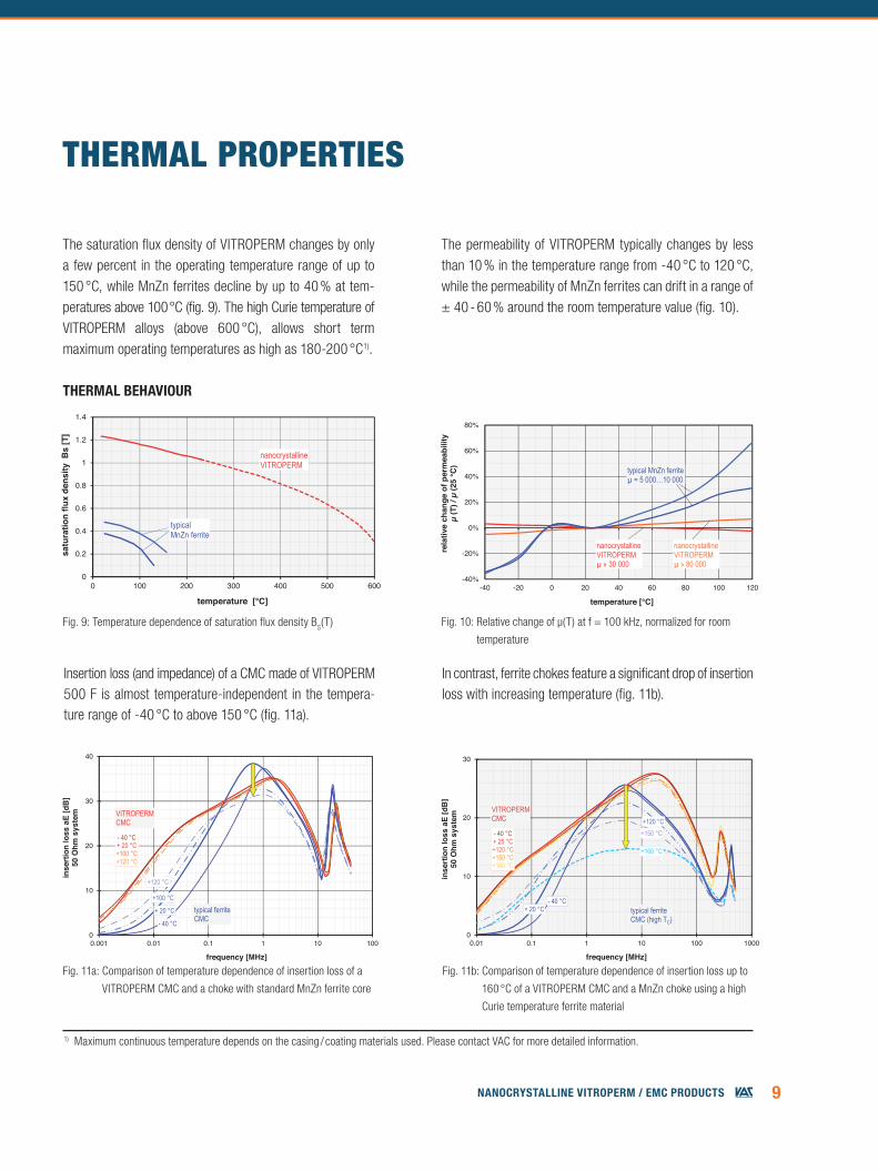
The saturation flux density of VITROPERM changes by only a few percent in the operating temperature range of up to 150 °C, while MnZn ferrites decline by up to 40 % at tem-peratures above 100 °C (fig. 9). The high Curie temperature of VITROPERM alloys (above 600 °C), allows short term maximum operating temperatures as high as 180-200 °C1).
The permeability of VITROPERM typically changes by less than 10 % in the temperature range from -40 °C to 120 °C, while the permeability of MnZn ferrites can drift in a range of ± 40 - 60 % around the room temperature value (fig. 10).
THERMaL PROPERTIES
Fig. 9: Temperature dependence of saturation flux density BS(T) Fig. 10: Relative change of µ(T) at f = 100 kHz, normalized for room
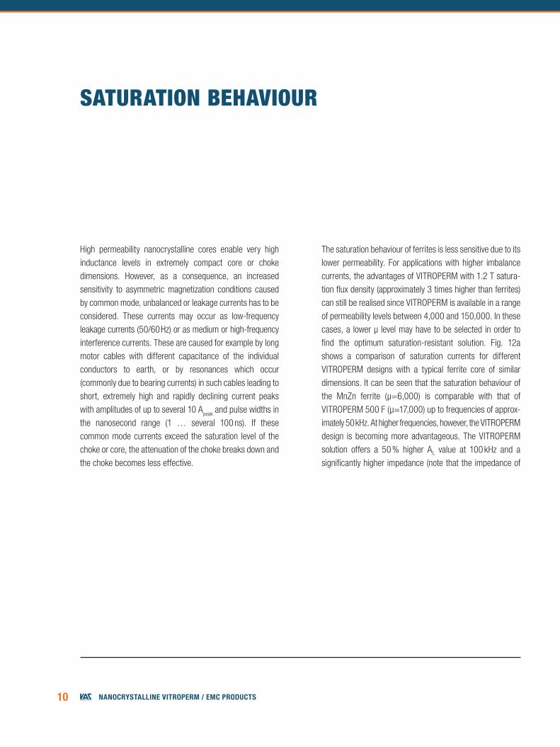
temperature
Fig. 11a: Comparison of temperature dependence of insertion loss of a
VITROPERM CMC and a choke with standard MnZn ferrite core
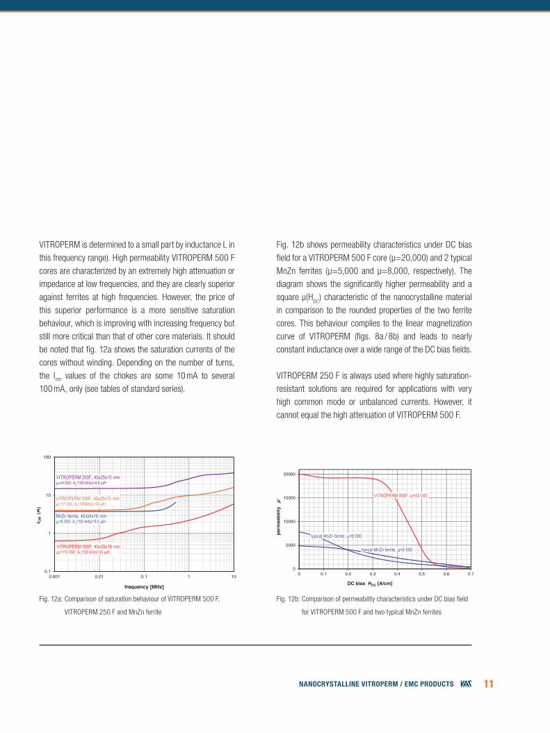
Fig. 11b: Comparison of temperature dependence of insertion loss up to
160 °C of a VITROPERM CMC and a MnZn choke using a high
Curie temperature ferrite material
1) Maximum continuous temperature depends on the casing / coating materials used. Please contact VAC for more detailed information.
therMAl behAviour
Insertion loss (and impedance) of a CMC made of VITROPERM 500 F is almost temperature-independent in the tempera-ture range of -40 °C to above 150 °C (fig. 11a).
In contrast, ferrite chokes feature a significant drop of insertion loss with increasing temperature (fig. 11b).
-40%
-20%
0%
20%
40%
60%
80%
-40 -20 0 20 40 60 80 100 120
rela
tive
chan
ge o
f per
mea
bilit
yµ
(T) /
µ (2
5 °C
)
temperature [°C]
nanocrystallineVITROPERMµ » 80 000
nanocrystallineVITROPERMµ » 30 000
typical MnZn ferriteµ = 5 000…10 000
Abb 9
11.03.2016Abb_04_05_06_07_08_09_10_11 en neu 2016.xls
KB-E K / Pe
0
0.2
0.4
0.6
0.8
1
1.2
1.4
0 100 200 300 400 500 600
satu
ratio
n flu
x de
nsity
Bs
[T]
temperature [°C]
nanocrystallineVITROPERM
typicalMnZn ferrite
Abb_04_05_06_07_08_09_10_11 en neu 2016.xls [Abb 11a]J. Beichler [11.03.2016 / 10:46]
0
10
20
30
40
0.001 0.01 0.1 1 10 100
inse
rtio
n lo
ss a
E [d
B]
50 O
hm s
yste
m
frequency [MHz]
- 40 °C
+100 °C
+120 °C
+ 20 °C typical ferriteCMC
VITROPERMCMC
- 40 °C+ 20 °C+100 °C+120 °C
Abb_04_05_06_07_08_09_10_11 en neu 2016.xls [Abb 11b]J. Beichler [11.03.2016 / 10:47]
0
10
20
30
0.01 0.1 1 10 100 1000
inse
rtio
n lo
ss a
E [d
B]
50 O
hm s
yste
m
frequency [MHz]
- 40 °Ctypical ferriteCMC (high TC)
+120 °C+150 °C
+ 20 °C
+160 °C
VITROPERMCMC
- 40 °C+ 25 °C+120 °C+150 °C+160 °C
10 NaNocrystalliNe Vitroperm / emc products
High permeability nanocrystalline cores enable very high inductance levels in extremely compact core or choke dimensions. However, as a consequence, an increased sensitivity to asymmetric magnetization conditions caused by common mode, unbalanced or leakage currents has to be considered. These currents may occur as low-frequency leakage currents (50/60 Hz) or as medium or high-frequency interference currents. These are caused for example by long motor cables with different capacitance of the individual conductors to earth, or by resonances which occur (commonly due to bearing currents) in such cables leading to short, extremely high and rapidly declining current peaks with amplitudes of up to several 10 A
peak and pulse widths in the nanosecond range (1 … several 100 ns). If these common mode currents exceed the saturation level of the choke or core, the attenuation of the choke breaks down and the choke becomes less effective.
The saturation behaviour of ferrites is less sensitive due to its lower permeability. For applications with higher imbalance currents, the advantages of VITROPERM with 1.2 T satura-tion flux density (approximately 3 times higher than ferrites) can still be realised since VITROPERM is available in a range of permeability levels between 4,000 and 150,000. In these cases, a lower µ level may have to be selected in order to find the optimum saturation-resistant solution. Fig. 12a shows a comparison of saturation currents for different VITROPERM designs with a typical ferrite core of similar dimensions. It can be seen that the saturation behaviour of the MnZn ferrite (µ=6,000) is comparable with that of VITROPERM 500 F (µ=17,000) up to frequencies of approx-imately 50 kHz. At higher frequencies, however, the VITROPERM design is becoming more advantageous. The VITROPERM solution offers a 50 % higher AL value at 100 kHz and a significantly higher impedance (note that the impedance of
SaTURaTIOn bEHaVIOUR
11NaNocrystalliNe Vitroperm / emc products
Fig. 12b: Comparison of permeability characteristics under DC bias field
for VITROPERM 500 F and two typical MnZn ferrites
Fig. 12a: Comparison of saturation behaviour of VITROPERM 500 F,
VITROPERM 250 F and MnZn ferrite
Johannes Beichler / KB-E IAAbb 12a / Abb_04_05_06_07_08_09_10_11 en neu 2016.xls [Seite 1/1]
Erstellt: 08.03.05 / 15:26
0.1
1
10
100
0.001 0.01 0.1 1 10
I CM
[A]
frequency [MHz]
MnZn ferrite, 40x24x16 mmµi=6 000, AL(100 kHz)=9.5 µH
VITROPERM 500F, 40x25x15 mmµi=110 000, AL(100 kHz)=24 µH
VITROPERM 500F, 40x25x15 mmµi=17 000, AL(100kHz)=14 µH
VITROPERM 250F, 40x25x15 mmµi=4 500, AL(100 kHz)=4.6 µH
Johannes Beichler / KB-E IAAbb.12b / Abb_04_05_06_07_08_09_10_11 en neu 2016.xls [Seite 1/1]
Erstellt: 08.03.05 / 15:26
0
5000
10000
15000
20000
0 0.1 0.2 0.3 0.4 0.5 0.6 0.7
perm
eabi
lity
µ'
DC bias HDC [A/cm]
VITROPERM 500F, µ=20 000
typical MnZn ferrite, µ=5 000
typical MnZn ferrite, µ=8 000
VITROPERM is determined to a small part by inductance L in this frequency range). High permeability VITROPERM 500 F cores are characterized by an extremely high attenuation or impedance at low frequencies, and they are clearly superior against ferrites at high frequencies. However, the price of this superior performance is a more sensitive saturation behaviour, which is improving with increasing frequency but still more critical than that of other core materials. It should be noted that fig. 12a shows the saturation currents of the cores without winding. Depending on the number of turns, the Icm values of the chokes are some 10 mA to several 100 mA, only (see tables of standard series).
Fig. 12b shows permeability characteristics under DC bias field for a VITROPERM 500 F core (µ=20,000) and 2 typical MnZn ferrites (µ=5,000 and µ=8,000, respectively). The diagram shows the significantly higher permeability and a square µ(H
DC) characteristic of the nanocrystalline material in comparison to the rounded properties of the two ferrite cores. This behaviour complies to the linear magnetization curve of VITROPERM (figs. 8a / 8b) and leads to nearly constant inductance over a wide range of the DC bias fields.
VITROPERM 250 F is always used where highly saturation-resistant solutions are required for applications with very high common mode or unbalanced currents. However, it cannot equal the high attenuation of VITROPERM 500 F.
12 NaNocrystalliNe Vitroperm / emc products
DESIgn aDVanTagES wITH VITROPERM
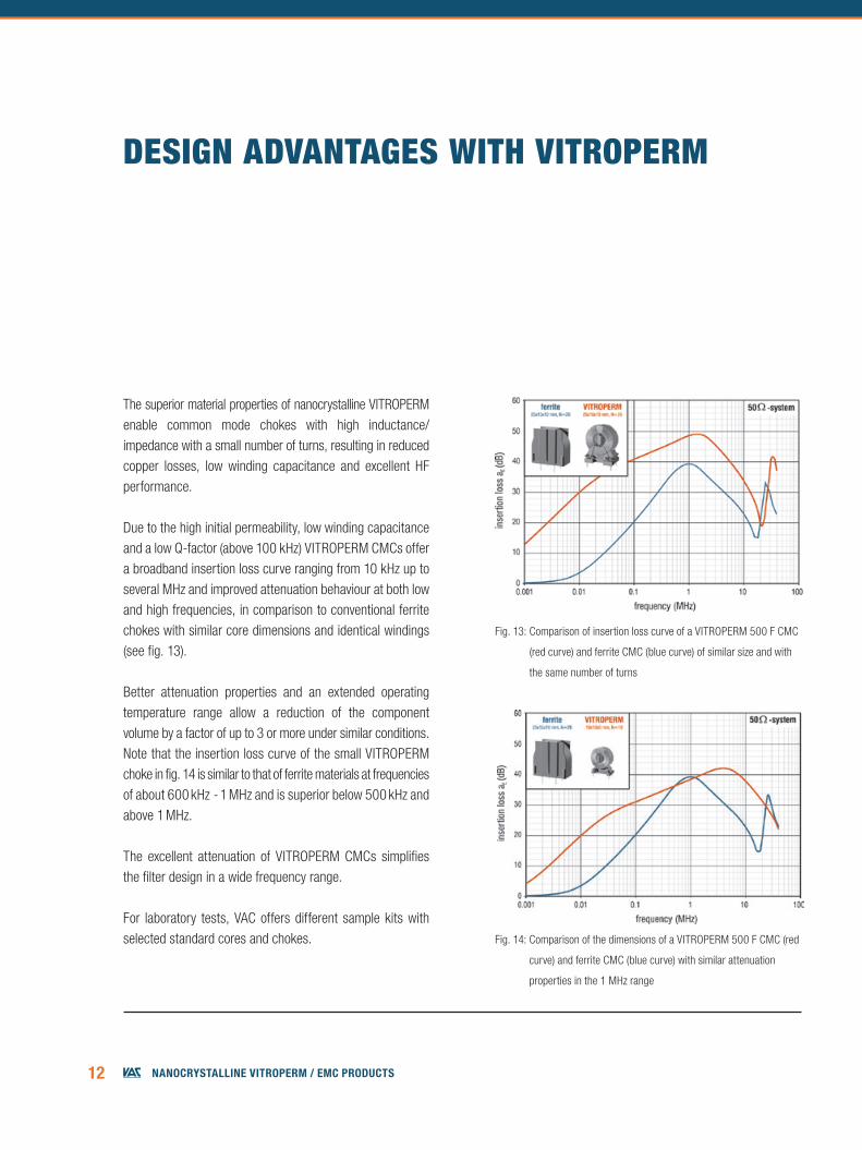
The superior material properties of nanocrystalline VITROPERM enable common mode chokes with high inductance/ impedance with a small number of turns, resulting in reduced copper losses, low winding capacitance and excellent HF performance.
Due to the high initial permeability, low winding capacitance and a low Q-factor (above 100 kHz) VITROPERM CMCs offer a broadband insertion loss curve ranging from 10 kHz up to several MHz and improved attenuation behaviour at both low and high frequencies, in comparison to conventional ferrite chokes with similar core dimensions and identical windings (see fig. 13).
Better attenuation properties and an extended operating temperature range allow a reduction of the component volume by a factor of up to 3 or more under similar conditions. Note that the insertion loss curve of the small VITROPERM choke in fig. 14 is similar to that of ferrite materials at frequencies of about 600 kHz - 1 MHz and is superior below 500 kHz and above 1 MHz.
The excellent attenuation of VITROPERM CMCs simplifies the filter design in a wide frequency range.
For laboratory tests, VAC offers different sample kits with selected standard cores and chokes.
Fig. 13: Comparison of insertion loss curve of a VITROPERM 500 F CMC
(red curve) and ferrite CMC (blue curve) of similar size and with
the same number of turns
Fig. 14: Comparison of the dimensions of a VITROPERM 500 F CMC (red
curve) and ferrite CMC (blue curve) with similar attenuation
properties in the 1 MHz range
13NaNocrystalliNe Vitroperm / emc products
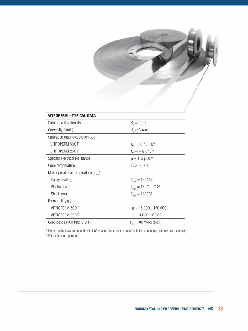
vitroPerM – tyPicAl dAtA
Saturation flux density BS = 1.2 T
Coercivity (static) HC < 3 A/m
Saturation magnetostriction (S)
VITROPERM 500 F S = 10-8….10-6
VITROPERM 250 F S = ≈ 8 x 10⁻⁶
Specific electrical resistance r ≈ 115 µΩcm
Curie temperature TC > 600 °C
Max. operational temperature (Tmax)
Epoxy coating Tmax = 120 °C2)
Plastic casing Tmax = 130/155 °C2)
Short-term Tmax = 180 °C1)
Permeability (µ)
VITROPERM 500 F µi = 15,000…150,000
VITROPERM 250 F µi = 4,000…6,000
Core losses (100 kHz, 0.3 T) PFe = 80 W/kg (typ.)
1) Please contact VAC for more detailed information about the temperature limits of our casing and coating materials.2) For continuous operation
14 NaNocrystalliNe Vitroperm / emc products
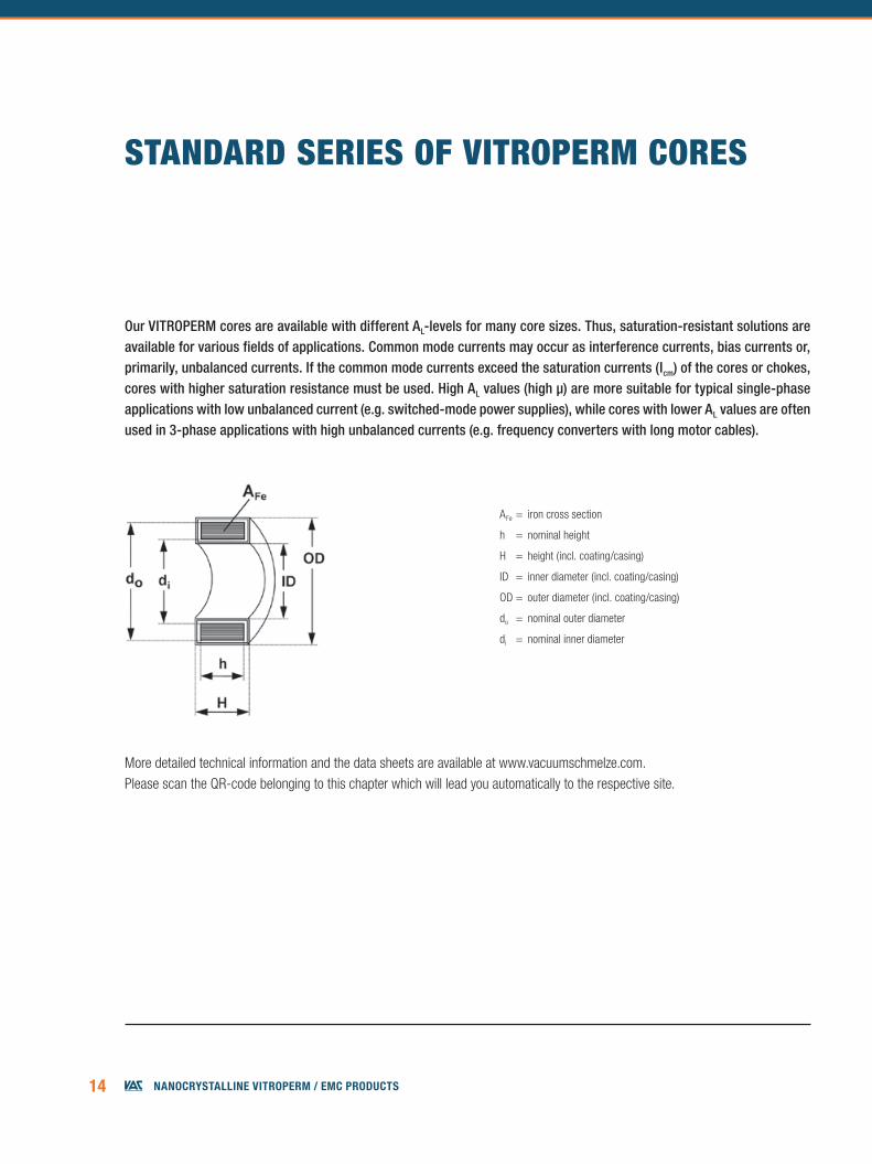
STanDaRD SERIES Of VITROPERM CORES
Our VITROPERM cores are available with different AL-levels for many core sizes. Thus, saturation-resistant solutions are available for various fields of applications. Common mode currents may occur as interference currents, bias currents or, primarily, unbalanced currents. If the common mode currents exceed the saturation currents (Icm) of the cores or chokes, cores with higher saturation resistance must be used. High AL values (high µ) are more suitable for typical single-phase applications with low unbalanced current (e.g. switched-mode power supplies), while cores with lower AL values are often used in 3-phase applications with high unbalanced currents (e.g. frequency converters with long motor cables).
More detailed technical information and the data sheets are available at www.vacuumschmelze.com. Please scan the QR-code belonging to this chapter which will lead you automatically to the respective site.
AFe = iron cross section
h = nominal height
H = height (incl. coating/casing)
ID = inner diameter (incl. coating/casing)
OD = outer diameter (incl. coating/casing)
do = nominal outer diameter
di = nominal inner diameter
15NaNocrystalliNe Vitroperm / emc products
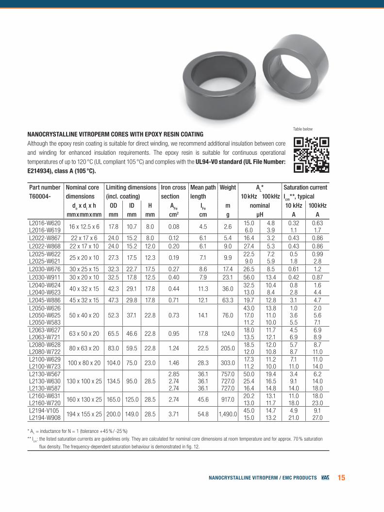
Part number Nominal core Limiting dimensions Iron cross Mean path Weight AL* Saturation currentT60004- dimensions (incl. coating) section length 10 kHz 100 kHz Icm**, typical
do x di x h OD ID H AFe IFe m nominal 10 kHz 100 kHzmm x mm x mm mm mm mm cm2 cm g µH A A
L2016-W620L2016-W619 16 x 12.5 x 6 17.8 10.7 8.0 0.08 4.5 2.6 15.0
6.04.83.9
0.321.1
0.631.7
L2022-W867 22 x 17 x 6 24.0 15.2 8.0 0.12 6.1 5.4 16.4 3.2 0.43 0.86L2022-W868 22 x 17 x 10 24.0 15.2 12.0 0.20 6.1 9.0 27.4 5.3 0.43 0.86L2025-W622L2025-W621 25 x 20 x 10 27.3 17.5 12.3 0.19 7.1 9.9 22.5
9.07.25.9
0.51.8
0.992.8
L2030-W676 30 x 25 x 15 32.3 22.7 17.5 0.27 8.6 17.4 26.5 8.5 0.61 1.2L2030-W911 30 x 20 x 10 32.5 17.8 12.5 0.40 7.9 23.1 56.0 13.4 0.42 0.87L2040-W624L2040-W623 40 x 32 x 15 42.3 29.1 17.8 0.44 11.3 36.0 32.5
13.010.48.4
0.8 2.8
1.64.4
L2045-W886 45 x 32 x 15 47.3 29.8 17.8 0.71 12.1 63.3 19.7 12.8 3.1 4.7L2050-W626L2050-W625 L2050-W583
50 x 40 x 20 52.3 37.1 22.8 0.73 14.1 76.043.017.0 11.2
13.811.0 10.0
1.03.6 5.5
2.05.6 7.1
L2063-W627L2063-W721 63 x 50 x 20 65.5 46.6 22.8 0.95 17.8 124.0 18.0
13.511.712.1
4.56.9
6.98.9
L2080-W628L2080-W722 80 x 63 x 20 83.0 59.5 22.8 1.24 22.5 205.0 18.5
12.012.010.8
5.78.7
8.711.0
L2100-W629L2100-W723 100 x 80 x 20 104.0 75.0 23.0 1.46 28.3 303.0 17.3
11.211.210.0
7.111.0
11.014.0
L2130-W567L2130-W630L2130-W587
130 x 100 x 25 134.5 95.0 28.52.852.742.74
36.136.136.1
757.0727.0727.0
50.025.416.4
19.416.514.8
3.49.1
14.0
6.214.018.0
L2160-W631L2160-W720 160 x 130 x 25 165.0 125.0 28.5 2.74 45.6 917.0 20.2
13.013.111.7
11.018.0
18.023.0
L2194-V105L2194-W908 194 x 155 x 25 200.0 149.0 28.5 3.71 54.8 1,490.0 45.0
15.014.713.2
4.921.0
9.1 27.0
nAnocrystAlline vitroPerM cores With ePoxy resin coAtingAlthough the epoxy resin coating is suitable for direct winding, we recommend additional insulation between core and winding for enhanced insulation requirements. The epoxy resin is suitable for continuous operational temperatures of up to 120 °C (UL compliant 105 °C) and complies with the ul94-v0 standard (ul File number: e214934), class A (105 °c).
* AL = inductance for N = 1 (tolerance +45 % / -25 %)
** Icm: the listed saturation currents are guidelines only. They are calculated for nominal core dimensions at room temperature and for approx. 70 % saturation
flux density. The frequency-dependent saturation behaviour is demonstrated in fig. 12.
Table below
16 NaNocrystalliNe Vitroperm / emc products
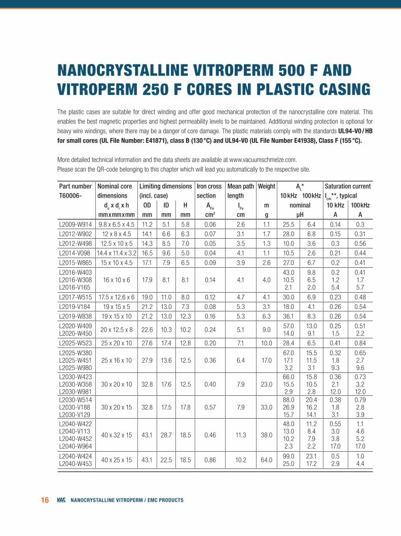
nanOCRYSTaLLInE VITROPERM 500 f anD VITROPERM 250 f CORES In PLaSTIC CaSIngThe plastic cases are suitable for direct winding and offer good mechanical protection of the nanocrystalline core material. This enables the best magnetic properties and highest permeability levels to be maintained. Additional winding protection is optional for heavy wire windings, where there may be a danger of core damage. The plastic materials comply with the standards ul94-v0 / hb for small cores (ul File number: e41871), class b (130 °c) and ul94-v0 (ul File number e41938), class F (155 °c).
Part number Nominal core Limiting dimensions Iron cross Mean path Weight AL* Saturation currentT60006- dimensions (incl. case) section length 10 kHz 100 kHz Icm**, typical
do x di x h OD ID H AFe IFe m nominal 10 kHz 100 kHzmm x mm x mm mm mm mm cm2 cm g µH A A
L2009-W914 9.8 x 6.5 x 4.5 11.2 5.1 5.8 0.06 2.6 1.1 25.5 6.4 0.14 0.3L2012-W902 12 x 8 x 4.5 14.1 6.6 6.3 0.07 3.1 1.7 28.0 6.8 0.15 0.31L2012-W498 12.5 x 10 x 5 14.3 8.5 7.0 0.05 3.5 1.3 10.0 3.6 0.3 0.56L2014-V098 14.4 x 11.4 x 3.2 16.5 9.6 5.0 0.04 4.1 1.1 10.5 2.6 0.21 0.44L2015-W865 15 x 10 x 4.5 17.1 7.9 6.5 0.09 3.9 2.6 27.0 6.7 0.2 0.41
L2016-W403L2016-W308 L2016-V165
16 x 10 x 6 17.9 8.1 8.1 0.14 4.1 4.043.010.5 2.1
9.86.5 2.0
0.21.2 5.4
0.411.7 5.7
L2017-W515 17.5 x 12.6 x 6 19.0 11.0 8.0 0.12 4.7 4.1 30.0 6.9 0.23 0.48L2019-V184 19 x 15 x 5 21.2 13.0 7.3 0.08 5.3 3.1 18.0 4.1 0.26 0.54L2019-W838 19 x 15 x 10 21.2 13.0 12.3 0.16 5.3 6.3 36.1 8.3 0.26 0.54
L2020-W409L2020-W450 20 x 12.5 x 8 22.6 10.3 10.2 0.24 5.1 9.0 57.0
14.013.09.1
0.251.5
0.512.2
L2025-W523 25 x 20 x 10 27.6 17.4 12.8 0.20 7.1 10.0 28.4 6.5 0.41 0.84
L2025-W380L2025-W451L2025-W980
25 x 16 x 10 27.9 13.6 12.5 0.36 6.4 17.067.017.13.2
15.511.53.1
0.321.89.3
0.652.79.6
L2030-W423L2030-W358L2030-W981
30 x 20 x 10 32.8 17.6 12.5 0.40 7.9 23.066.015.52.9
15.810.52.8
0.362.1
12.0
0.73 3.212.0
L2030-W514 L2030-V188L2030-V129
30 x 20 x 15 32.8 17.5 17.8 0.57 7.9 33.088.0 26.9 15.7
20.4 16.2 14.1
0.38 1.8 3.1
0.79 2.8 3.9
L2040-W422 L2040-V113L2040-W452L2040-W964
40 x 32 x 15 43.1 28.7 18.5 0.46 11.3 38.0
48.0 13.010.22.3
11.2 8.47.92.2
0.55 3.03.817.0
1.1 4.65.217.0
L2040-W424L2040-W453 40 x 25 x 15 43.1 22.5 18.5 0.86 10.2 64.0 99.0
25.023.117.2
0.52.9
1.04.4
More detailed technical information and the data sheets are available at www.vacuumschmelze.com.Please scan the QR-code belonging to this chapter which will lead you automatically to the respective site.
17NaNocrystalliNe Vitroperm / emc products
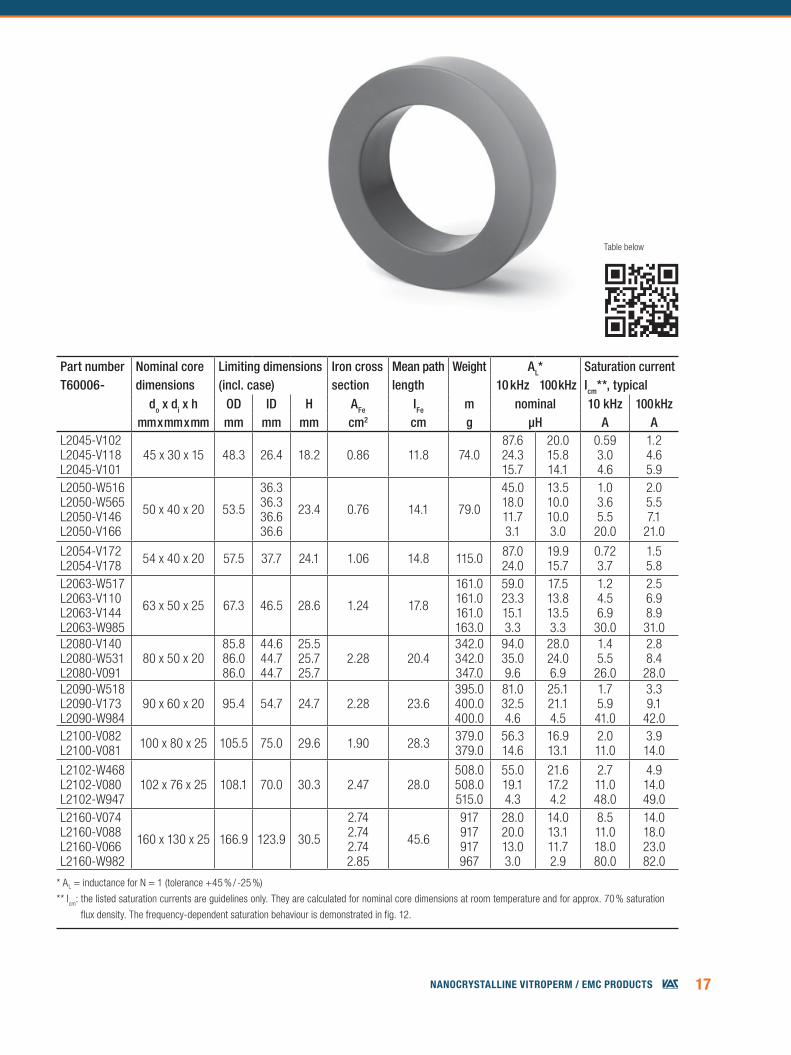
* AL = inductance for N = 1 (tolerance +45 % / -25 %)
** Icm: the listed saturation currents are guidelines only. They are calculated for nominal core dimensions at room temperature and for approx. 70 % saturation
flux density. The frequency-dependent saturation behaviour is demonstrated in fig. 12.
Part number Nominal core Limiting dimensions Iron cross Mean path Weight AL* Saturation currentT60006- dimensions (incl. case) section length 10 kHz 100 kHz Icm**, typical
do x di x h OD ID H AFe IFe m nominal 10 kHz 100 kHzmm x mm x mm mm mm mm cm2 cm g µH A A
L2045-V102L2045-V118L2045-V101
45 x 30 x 15 48.3 26.4 18.2 0.86 11.8 74.087.624.315.7
20.015.814.1
0.593.04.6
1.24.65.9
L2050-W516 L2050-W565 L2050-V146 L2050-V166
50 x 40 x 20 53.5
36.3 36.3 36.6 36.6
23.4 0.76 14.1 79.0
45.018.0 11.7 3.1
13.510.0 10.0 3.0
1.03.6 5.5 20.0
2.0 5.5 7.1
21.0
L2054-V172L2054-V178 54 x 40 x 20 57.5 37.7 24.1 1.06 14.8 115.0 87.0
24.019.9 15.7
0.72 3.7
1.5 5.8
L2063-W517L2063-V110 L2063-V144L2063-W985
63 x 50 x 25 67.3 46.5 28.6 1.24 17.8
161.0161.0 161.0163.0
59.023.3 15.13.3
17.513.8 13.53.3
1.24.5 6.9
30.0
2.56.9 8.931.0
L2080-V140L2080-W531 L2080-V091
80 x 50 x 2085.8 86.0 86.0
44.6 44.7 44.7
25.5 25.7 25.7
2.28 20.4342.0 342.0347.0
94.035.0 9.6
28.024.0 6.9
1.45.5
26.0
2.88.4
28.0L2090-W518 L2090-V173L2090-W984
90 x 60 x 20 95.4 54.7 24.7 2.28 23.6395.0 400.0400.0
81.0 32.54.6
25.1 21.14.5
1.7 5.941.0
3.3 9.1
42.0L2100-V082 L2100-V081 100 x 80 x 25 105.5 75.0 29.6 1.90 28.3 379.0
379.056.3 14.6
16.9 13.1
2.0 11.0
3.9 14.0
L2102-W468L2102-V080L2102-W947
102 x 76 x 25 108.1 70.0 30.3 2.47 28.0508.0508.0515.0
55.019.14.3
21.617.24.2
2.711.048.0
4.914.049.0
L2160-V074L2160-V088L2160-V066L2160-W982
160 x 130 x 25 166.9 123.9 30.5
2.742.742.742.85
45.6
917917917967
28.020.013.03.0
14.013.111.72.9
8.511.018.080.0
14.018.023.082.0
Table below
18 NaNocrystalliNe Vitroperm / emc products
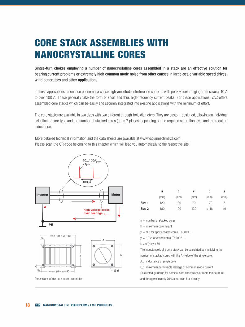
CORE STaCk aSSEMbLIES wITH nanOCRYSTaLLInE CORESSingle-turn chokes employing a number of nanocrystalline cores assembled in a stack are an effective solution for bearing current problems or extremely high common mode noise from other causes in large-scale variable speed drives, wind generators and other applications.
In these applications resonance phenomena cause high-amplitude interference currents with peak values ranging from several 10 A to over 100 A. These generally take the form of short and thus high-frequency current peaks. For these applications, VAC offers assembled core stacks which can be easily and securely integrated into existing applications with the minimum of effort.
The core stacks are available in two sizes with two different through-hole diameters. They are custom-designed, allowing an individual selection of core type and the number of stacked cores (up to 7 pieces) depending on the required saturation level and the required inductance.
Dimensions of the core stack assemblies
n = number of stacked cores
H = maximum core height
y = 9.5 for epoxy coated cores, T60004…
y = 10.2 for cased cores, T60006…
L = n*(H+y)+60
The inductance L of a core stack can be calculated by multiplying the
number of stacked cores with the AL-value of the single core.
AL: inductance of single core
Icm: maximum permissible leakage or common mode current
Calculated guideline for nominal core dimensions at room temperature
and for approximately 70 % saturation flux density.
More detailed technical information and the data sheets are available at www.vacuumschmelze.com.Please scan the QR-code belonging to this chapter which will lead you automatically to the respective site.
a b c d s
(mm) (mm) (mm) (mm) (mm)
size 1 120 130 70 ~ 70 7
size 2 180 190 130 >118 10
19NaNocrystalliNe Vitroperm / emc products
core dAtA dAtA oF core stAcK exAMPle For 5 stAcKed cores
Core part number Nominal core Limit core dimensions AL Size Icm Ldimensions (incl. case/coating) 10 kHz 100 kHz 10 kHz 100 kHz 10 kHz 100 kHz
do x di x h OD ID H nominal typical nominalmm x mm x mm mm mm mm µH A µH
T60004-L2100-W629 100 x 80 x 20 104.0 75.0 23.0 17.3 11.2 1 7.1 11.0 86.5 56.0T60004-L2100-W723 100 x 80 x 20 104.0 75.0 23.0 11.2 10.0 1 11.0 14.0 56.0 50.0T60006-L2100-V082 100 x 80 x 25 105.5 75.0 29.6 56.3 16.9 1 2.0 3.9 281.5 84.5T60006-L2100-V081 100 x 80 x 25 105.5 75.0 29.6 14.6 13.1 1 11.0 14.0 73.0 65.5T60006-L2102-W468 102 x 76 x 25 108.1 70.0 30.3 69.4 21.5 1 2.1 4.1 347.0 108.0T60006-L2102-V080 102 x 76 x 25 108.1 70.0 30.3 19.1 17.2 1 11.0 14.0 95.5 86.0T60006-L2102-W947 102 x 76 x 25 108.1 70.0 30.3 4.3 4.2 1 48.0 49.0 21.5 21.0T60006-L2160-V074 160 x 130 x 25 166.9 123.9 30.5 28.0 14.0 2 8.5 14.0 140.0 70.0T60006-L2160-V088 160 x 130 x 25 166.9 123.9 30.5 20.0 13.1 2 11.0 18.0 100.0 65.5T60006-L2160-V066 160 x 130 x 25 166.9 123.9 30.5 13.0 11.7 2 18.0 23.0 65.0 58.5T60006-L2160-W982 160 x 130 x 25 166.9 123.9 30.5 3.0 2.9 2 80.0 82.0 15.0 14.5
existing core stacks
Core stack part number
Nominal core dimensions (part number) x number of cores
Nominal core stack dimensions
AL Size Icm
10 kHz 100 kHz 10 kHz 100 kHz
do x di x hbase
dimension (L x a)
height (b)
nominal typical
mm x mm x mm mm mm µH AT60016-L2102-W075 102 x 76 x 25 (W947) x 2 140 x 120 130 9.1 8.4 1 48 49T60016-L2102-W078 102 x 76 x 25 (W468) x 6 300 x 120 130 416 130 1 2.1 4.1T60016-L2160-W076 160 x 130 x 25 (W982) x 5 261 x 180 190 16 14.5 2 80 82T60016-L2160-W079 160 x 130 x 25 (V066) x 4 210 x 180 190 52 46.8 2 18 23T60016-L2160-W080 160 x 130 x 25 (V066) x 7 310 x 180 190 91 81.9 2 18 23T60016-L2160-W081 160 x 130 x 25 (V066) x 5 240 x 180 190 65 58.5 2 18 23
In case of interest for a specific core stack with 2-7 cores chosen from above list please contact VAC.
Table below
20 NaNocrystalliNe Vitroperm / emc products
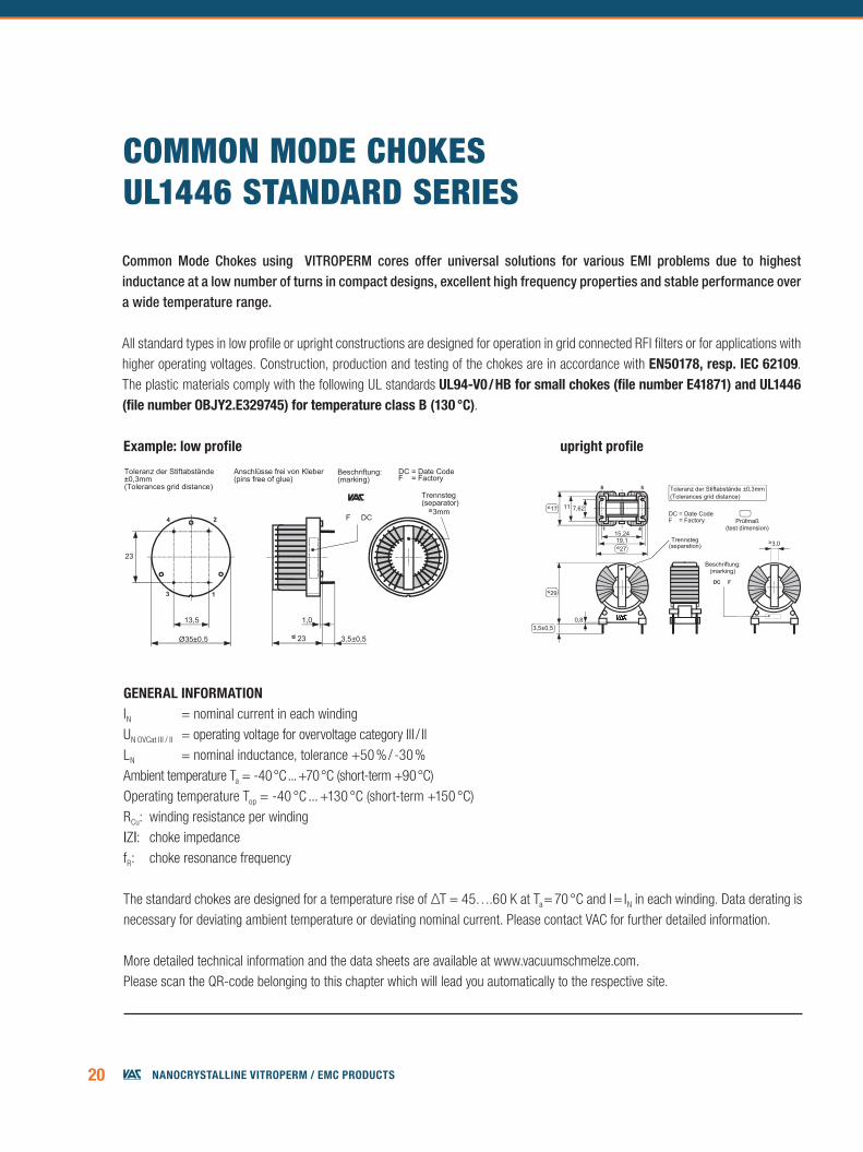
COMMOn MODE CHOkESUL1446 STanDaRD SERIES
generAl inForMAtionIN = nominal current in each windingUN OVCat III / II = operating voltage for overvoltage category III / IILN = nominal inductance, tolerance +50 % / -30 %Ambient temperature Ta = -40 °C ... +70 °C (short-term +90 °C)Operating temperature Top = -40 °C ... +130 °C (short-term +150 °C)RCu: winding resistance per winding |Z|: choke impedance fR: choke resonance frequency
The standard chokes are designed for a temperature rise of ΔT = 45….60 K at Ta = 70 °C and I = IN in each winding. Data derating is necessary for deviating ambient temperature or deviating nominal current. Please contact VAC for further detailed information. More detailed technical information and the data sheets are available at www.vacuumschmelze.com.Please scan the QR-code belonging to this chapter which will lead you automatically to the respective site.
5-R6123-X210
≤ 23
DC = Date CodeF = Factory
Toleranz der Stiftabstände±0,3mm(Tolerances grid distance)
F DC
3,5±0,5
1,0
Ø35±0,5
Trennsteg(separator)
Beschriftung:(marking)
Anschlüsse frei von Kleber(pins free of glue)
≥3mm
23
13,5
3
4 2
1
5-R6161-X504
15,241
8 5
4
Toleranz der Stiftabstände ±0,3mm(Tolerances grid distance)
DC = Date CodeF = Factory
Beschriftung:(marking)
DC F
19,1
7,6211
0,8
Trennsteg(separation)
≥3,0
Prüfmaß(test dimension)
≤17
≤29
3,5±0,5
≤27
Common Mode Chokes using VITROPERM cores offer universal solutions for various EMI problems due to highest inductance at a low number of turns in compact designs, excellent high frequency properties and stable performance over a wide temperature range.
All standard types in low profile or upright constructions are designed for operation in grid connected RFI filters or for applications with higher operating voltages. Construction, production and testing of the chokes are in accordance with en50178, resp. iec 62109. The plastic materials comply with the following UL standards ul94-v0 / hb for small chokes (file number e41871) and ul1446 (file number obJy2.e329745) for temperature class b (130 °c).
example: low profile upright profile
21NaNocrystalliNe Vitroperm / emc products
STANDARD SERIES CMCs FOR 1-PHASE APPLICATIONSPart number IN Design UN LN RCu |Z| fR Icm DimensionsT60405- OVCat III / II 10 kHz 100 kHz 100 kHz 10 kHz l w h
A V mH mH mΩ Ω MHz mA mm mm mmR6131-X402 2 upright 300 / 600 2 x 12.1 2 x 2.8 101.7 3000 3.6 12 22 12 25R6131-X204 4.5 upright 300 / 600 2 x 10.8 2 x 2.5 27.5 2320 1 12 22 12 25R6161-X504 5 upright 300 / 600 2 x 28.3 2 x 6.6 35.6 6500 0.4 10 27 17 29R6166-X206 6 upright 300 / 600 2 x 29.1 2 x 6.7 37.6 8500 0.25 14 35 21 37R6166-X208 8.5 upright 300 / 600 2 x 16.4 2 x 3.7 19.1 4200 0.5 17 35 21 36.5R6123-X210 10 low profile 300 / 600 2 x 11.4 2 x 2.6 12 3200 0.7 16 35 35 23R6166-X210 10 upright 300 / 600 2 x 11.4 2 x 2.6 12.7 3150 0.7 16 35 21 37R6126-X212 12 upright 300 / 600 2 x 11.4 2 x 2.6 9 2950 0.7 22 38 22 35R6123-X213 12.4 low profile 300 / 600 2 x 11.4 2 x 2.6 8.8 2950 0.7 22 35 35 25R6122-X095 13.5 upright 600 / 1000 2 x 16.9 2 x 3.6 7.6 4000 0.7 22 41 21 37R6102-X016 13 low profile 300 / 600 2 x 8.6 2 x 2.2 6.3 2250 1.1 28 35 35 22.5R6123-X616 16 low profile 300 / 600 2 x 12.9 2 x 3.1 5.7 3000 3 26 40 40 24R6126-X216 16 upright 600 / 1000 2 x 5.3 2 x 1.3 2.8 1300 3.5 40 41.5 23.5 40R6166-X033 18 upright 300 / 600 2 x 6 2 x 1.5 4.6 1600 1 35 38 21 38R6166-X039 18 upright 300 / 600 2 x 2.9 2 x 0.7 3.9 830 3.3 50 36 21 38R6123-X220 20.5 low profile 300 / 600 2 x 1.8 2 x 0.4 3.2 500 11.5 40 35 35 23.5R6123-X221 20 low profile 300 / 600 2 x 6.6 2 x 1.6 2.9 1470 4.5 35 43 43 24R6128-X220 20 upright 600 /1000 2 x 5.6 2 x 1.3 2.8 1300 3.6 40 42 27 38R6123-X226 25 low profile 300 / 600 2 x 4.2 2 x 1 1.9 970 7.1 45 43 39.5 25R6123-X227 25 low profile 600 / 1000 2 x 12 2 x 2.8 3.5 2900 2.2 45 52 52 32R6128-X225 25 upright 300 / 600 2 x 4.2 2 x 1 1.9 970 4.9 45 42 27 40R6128-X226 25 upright 600 / 1000 2 x 12 2 x 2.8 3.3 3000 1.5 40 52 28.5 48.5R6123-X232 30 low profile 600 / 1000 2 x 3.9 2 x 0.9 2.4 920 7 50 52 52 29R6128-X031 30 upright 600 / 1000 2 x 3.9 2 x 0.9 2.3 900 4 65 51 27 50R6128-X230 30 upright 600 / 1000 2 x 6.3 2 x 1.5 2.3 1620 2.7 55 52 27 47R6123-X241 40 low profile 600 / 1000 2 x 3.6 2 x 0.8 1.4 870 6 90 52 52 32R6123-X248 46 low profile 600 / 1000 2 x 2.5 2 x 0.6 1 660 5.7 100 57 51 33R6123-X263 63 low profile 600 / 1000 2 x 1.6 2 x 0.4 0.5 390 9.3 120 56 56 32R6123-X285 85 low profile 600 / 1000 2 x 1.6 2 x 0.5 0.6 510 1.6 200 73 73 40
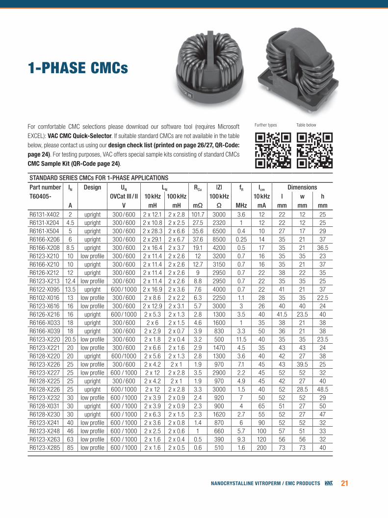
1-PHaSE CMCs
For comfortable CMC selections please download our software tool (requires Microsoft EXCEL): vAc cMc Quick-selector. If suitable standard CMCs are not available in the table below, please contact us using our design check list (printed on page 26/27, Qr-code: page 24). For testing purposes, VAC offers special sample kits consisting of standard CMCs cMc sample Kit (Qr-code page 24).
Further types Table below
22 NaNocrystalliNe Vitroperm / emc products
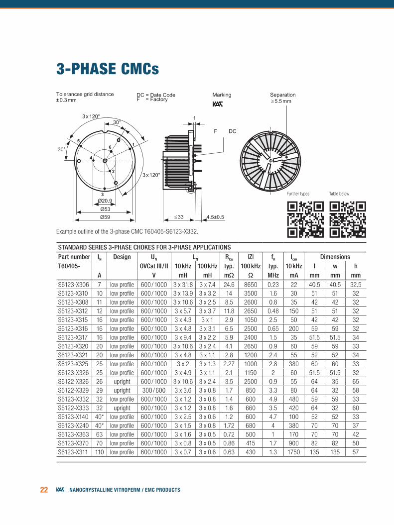
STANDARD SERIES 3-PHASE CHOKES FOR 3-PHASE APPLICATIONSPart number IN Design UN LN RCu |Z| fR Icm DimensionsT60405- OVCat III / II 10 kHz 100 kHz typ. 100 kHz typ. 10 kHz l w h
A V mH mH mΩ Ω MHz mA mm mm mmS6123-X306 7 low profile 600 / 1000 3 x 31.8 3 x 7.4 24.6 8650 0.23 22 40.5 40.5 32.5S6123-X310 10 low profile 600 / 1000 3 x 13.9 3 x 3.2 14 3500 1.6 30 51 51 32S6123-X308 11 low profile 600 / 1000 3 x 10.6 3 x 2.5 8.5 2600 0.8 35 42 42 32S6123-X312 12 low profile 600 / 1000 3 x 5.7 3 x 3.7 11.8 2650 0.48 150 51 51 32S6123-X315 16 low profile 600 / 1000 3 x 4.3 3 x 1 2.9 1050 2.5 50 42 42 32S6123-X316 16 low profile 600 / 1000 3 x 4.8 3 x 3.1 6.5 2500 0.65 200 59 59 32S6123-X317 16 low profile 600 / 1000 3 x 9.4 3 x 2.2 5.9 2400 1.5 35 51.5 51.5 34S6123-X320 20 low profile 600 / 1000 3 x 10.6 3 x 2.4 4.1 2650 0.9 60 59 59 33S6123-X321 20 low profile 600 / 1000 3 x 4.8 3 x 1.1 2.8 1200 2.4 55 52 52 34S6123-X325 25 low profile 600 / 1000 3 x 2 3 x 1.3 2.27 1000 2.8 380 60 60 33S6123-X326 25 low profile 600 / 1000 3 x 4.9 3 x 1.1 2.1 1150 2 60 51.5 51.5 32S6122-X326 26 upright 600 / 1000 3 x 10.6 3 x 2.4 3.5 2500 0.9 55 64 35 65S6122-X329 29 upright 300 / 600 3 x 3.6 3 x 0.8 1.7 850 3.3 80 64 32 58S6123-X332 32 low profile 600 / 1000 3 x 1.2 3 x 0.8 1.4 600 4.9 480 59 59 33S6122-X333 32 upright 600 / 1000 3 x 1.2 3 x 0.8 1.6 660 3.5 420 64 32 60S6123-X140 40* low profile 600 / 1000 3 x 2.5 3 x 0.6 1.2 600 4.7 100 52 52 33S6123-X240 40* low profile 600 / 1000 3 x 1.5 3 x 0.8 1.72 680 4 380 70 70 37S6123-X363 63 low profile 600 / 1000 3 x 1.6 3 x 0.5 0.72 500 1 170 70 70 42S6123-X370 70 low profile 600 / 1000 3 x 0.8 3 x 0.5 0.86 415 1.7 900 82 82 50S6123-X311 110 low profile 600 / 1000 3 x 0.7 3 x 0.6 0.63 430 1.3 1750 135 135 57
3-PHaSE CMCs
Example outline of the 3-phase CMC T60405-S6123-X332.
SeparationMarking
Further types Table below
23NaNocrystalliNe Vitroperm / emc products
STANDARD SERIES 4-FOLD CHOKES Part number IN Design UN LN RCu |Z| fR Icm DimensionsT60405- OVCat III / II 10 kHz 100 kHz typ. 100 kHz typ. 10 kHz l w h
A V mH mH mΩ Ω MHz mA mm mm mm
S6123-X40010**12*
low profile 600 / 1000 4 x 6.9 4 x 1.6 7.66 1500 1.4 40 51 51 33
S6123-X40116**20*
low profile 600 / 1000 4 x 3.6 4 x 0.8 2.75 860 3.4 90 51.5 51.5 33
S6123-X40224** 30*
low profile 600 / 1000 4 x 3.2 4 x 0.7 1.5 750 3.5 100 60 60 33.5
S6123-X40332** 40*
low profile 600 / 1000 4 x 1.4 4 x 0.3 0.82 360 7 160 60 60 33
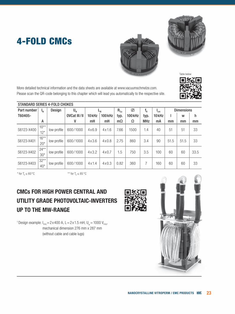
4-fOLD CMCs
* for Ta ≤ 60 °C ** for Ta ≤ 85 °C
1 Design example: Irms = 2 x 400 A, L = 2 x 1.5 mH, Uis = 1000 Vrms, mechanical dimension 276 mm x 287 mm (without cable and cable lugs)
Table below
More detailed technical information and the data sheets are available at www.vacuumschmelze.com. Please scan the QR-code belonging to this chapter which will lead you automatically to the respective site.
cMcs For high PoWer centrAl And
utility grAde PhotovoltAic-inverters
uP to the MW-rAnge
24 NaNocrystalliNe Vitroperm / emc products
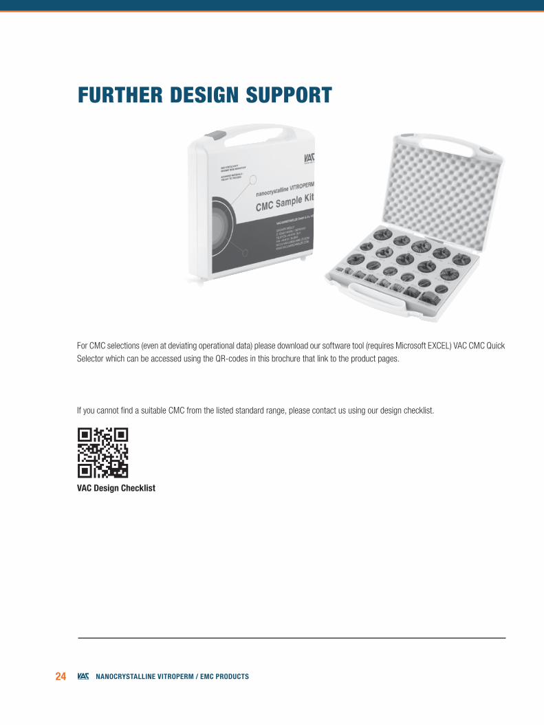
fURTHER DESIgn SUPPORT
For CMC selections (even at deviating operational data) please download our software tool (requires Microsoft EXCEL) VAC CMC Quick Selector which can be accessed using the QR-codes in this brochure that link to the product pages.
If you cannot find a suitable CMC from the listed standard range, please contact us using our design checklist.
vAc design checklist
25NaNocrystalliNe Vitroperm / emc products
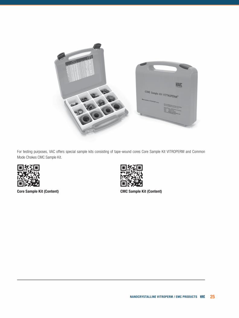
For testing purposes, VAC offers special sample kits consisting of tape-wound cores Core Sample Kit VITROPERM and Common Mode Chokes CMC Sample Kit.
core sample Kit (content) cMc sample Kit (content)
26 NaNocrystalliNe Vitroperm / emc products
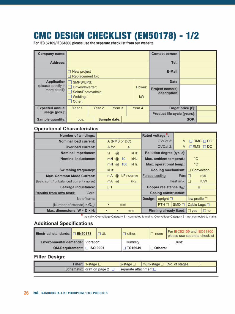
CMC Design Checklist April 2016
VACUUMSCHMELZE GMBH & Co. KG P.O. Box 2253, D-63412 Hanau, Germany mail: [email protected] Tel: +49 6181 38-0 FAX: +49 6181 382066 [08.04.2016] / page 1 of 2
NOTE: The yellow fields contain basic information. Please fill in all available data. The white fields contain additional background information.
Company name:
Contact person:
Address:
Tel.:
New project
Replacement for:
E-Mail:
Application (please specify in
more detail):
SMPS/UPS:
Drives/Inverter:
Solar/Photovoltaic:
Welding:
Other:
Power:
kW
Date:
Project name(s), description:
Expected annual usage [pcs.]:
Year 1
Year 2
Year 3
Year 4
Target price [€]:
Product life cycle [years]:
Sample quantity:
pcs. Sample date:
SOP:
Operational Characteristics Number of windings:
Rated voltage 1): OVCat 3: OVCat 2:
V RMS DC
V RMS DC Nominal load current:
A (RMS or DC) Overload current:
A for
s
Nominal impedance:
Ω @
kHz Pollution degree (typ. 2):
Nominal inductance:
mH @ 10 kHz
mH @ 100 kHz Max. ambient temperat.: Max. operational temp.:
°C
°C Switching frequency:
kHz Cooling mechanism: Convection
Max. Common Mode Current: (leak. curr. / unbalanced current / noise)
mA @ LF (<20kHz)
mA @
kHz Forced cooling Fan:
Heat sink:
m/s
K/W
Leakage inductance:
µH Copper resistance RCu:
Ω Results from own tests: Core:
Casing construction:
No of turns:
Design: upright low profile
(Number of strands) × ØCu:
×
mm PTH SMD Cable Lugs
Max. dimensions: W × D × H:
×
×
mm Pinning already fixed: yes no 1) typically: Overvoltage Category 3 = connected to mains, Overvoltage Category 2 = not connected to mains
Additional Specifications
Electrical standards: EN50178 UL
other:
none For IEC62109 and IEC61800 please use separate checklist
Environmental demands: Vibration:
Humidity:
Dust:
QM-Requirement: ISO 9001 TS16949 Others:
Filter Design: Filter: 1-stage 2-stage multi-stage (No. of stages:
) Schematic: draft on page 2 separate attachment
CMC DESIgn CHECkLIST (En50178) - 1/2For iec 62109/iec61800 please use the separate checklist from our website.
27NaNocrystalliNe Vitroperm / emc products
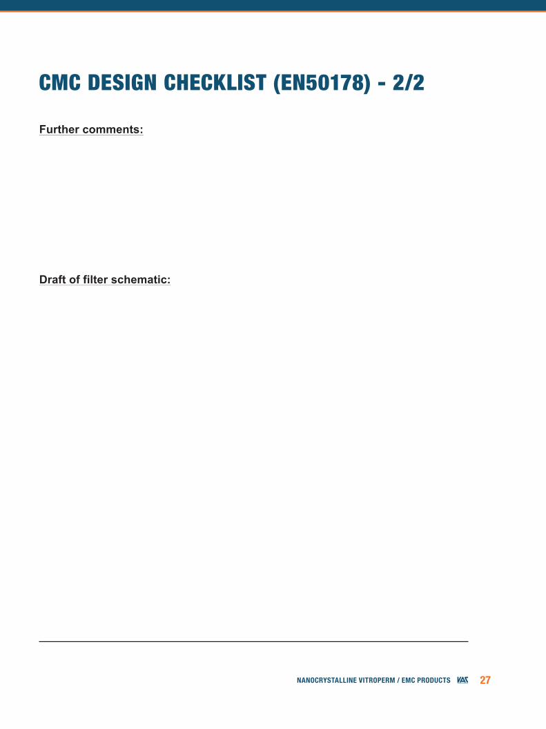
CMC DESIgn CHECkLIST (En50178) - 2/2
- 2 -
A CMC Design Checklist April 2016
VACUUMSCHMELZE GMBH & Co. KG P.O. Box 2253, D-63412 Hanau, Germany mail: [email protected] Tel: +49 6181 38-0 FAX: +49 6181 382066 [08.04.2016] / page 2 of 2
Further comments:
Draft of filter schematic:
Pb-eMc eMc Products bAsed on nAnocrystAlline vitroPerM • edition 2016
Published by VACUUMSCHMELZE GmbH & Co. KG, Hanau© VACUUMSCHMELZE GmbH & Co. KG 2016. All rights reserved.
® is a registered trademark of VACUUMSCHMELZE GmbH & Co. KG
vAcuuMschMelze singAPore Pte ltd1 TAMPINES CENTRAL 5, #06-09CPF TAMPINES BUILDINGSINGAPORE 529508PHONE +65 6391 2600FAX +65 6391 [email protected]
vAc MAgnetics llc2935 DOLPHIN DRIVESUITE 102ELIZABETHTOWN, Ky 42701 PHONE +1 270 769 1333FAX +1 270 769 [email protected]
vAcuuMschMelze gMbh & co. KgGRüNER WEG 37D 63450 HANAU / GERMANyPHONE +49 6181 38 0FAX +49 6181 38 [email protected]
vAcuuMschMelze chinA MAgneticsSHANGHAI SALES OFFICEROOM 06, 19F ZHONGRONG HENGRUI INTERNATIONAL PLAZA620 ZHANGyANG ROAD, PUDONG DISTRICTSHANGHAI, PRC 200122PHONE +86 21 58 31 98 37FAX +86 21 58 31 99 [email protected]
AdvAnced MAteriAls – the Key to Progress

![SCISCITATOR 2015 · [1]. Riverine communities experience two main types of disturbances: natural disturbances and anthropogenic disturbances. Natural disturbances in riverine ecosystems](https://img.pdfslide.us/doc/110x75/5f27dd3959f0c41da22eeec5/sciscitator-1-riverine-communities-experience-two-main-types-of-disturbances.jpg)