Embed Size (px)
DESCRIPTION
EMC PLAN FOR METRO LINE. This is a document for total design of installation without risks conditions in electrical installations and communications systems
Citation preview

7/18/2019 EMC plan for metro ps
http://slidepdf.com/reader/full/emc-plan-for-metro-ps 1/14
ISTANBUL METRO - STAGE 1
E.M.C.
ASSURANCE PLAN
7/18/2019 EMC plan for metro ps
http://slidepdf.com/reader/full/emc-plan-for-metro-ps 2/14
ISTANBUL METRO – Stage 1 Electromechanical Works
EMC_a.doc 2 / 14 30/08/1999
TABLE OF CONTENTS
A faire svp – Merci…
7/18/2019 EMC plan for metro ps
http://slidepdf.com/reader/full/emc-plan-for-metro-ps 3/14
ISTANBUL METRO – Stage 1 Electromechanical Works
EMC_a.doc 3 / 14 30/08/1999
1. INTRODUCTION
This document aims to demonstrate that Electro-Magnetic Compatibility has been carefullystudied throughout the design phase of the Istanbul Metro, and that convenient measures
actually have been applied during construction phase, in order to guarantee the requirement
of the Contract which specifies:
“ All electrical and electronic equipment shall be designed to operate correctly without
degradation of quality, performance or loss of function in the electromagnetic environment
produced by the system.”
General matters about EMC are reminded in the first section.
Then, the basic principles that were applied to the overall design are presented.
A detailed analysis of the possible interference’s in the Metro System follows. It will be
demonstrated that convenient countermeasures have been applied either by the here above
basic principles, or through “ad hoc” measures.
Thus, most of the interference’s will be demonstrated as solved. Particular cases are referred
to be dealt with in specific documents and/or procedures.
2. GENERAL - REMINDERS
Let us first remind what is the ELECTRO-MAGNETIC COMPATIBILITY of an installation:
It is the ability of the components (i.e. apparatuses) :
Relevant issue
to generate electromagnetic interference’s of a limited
level enabling other apparatuses located in the vicinity
to work in compliance with the function for which they
are designed,
EMISSION
to have a sufficient level of immunity against
electromagnetic interference in order to work correctlywithin the environment for which they are designed.
IMMUNITY
7/18/2019 EMC plan for metro ps
http://slidepdf.com/reader/full/emc-plan-for-metro-ps 4/14
ISTANBUL METRO – Stage 1 Electromechanical Works
EMC_a.doc 4 / 14 30/08/1999
The coupling modes that support electromagnetic interference are numerous and are applicable within different frequency ranges:
Coupling modes Frequency range Phenomenon
Conductive coupling (common conduction path)
Capacitive coupling (mutual capacitance)
Electrostatic coupling (ESDischarge transfer)
LF / HF
HF
HF
CONDUCTION
Inductive coupling(induced voltage by magnetic field)
Radiation (circuits = antenna for E/H)
LF / HF
HF
INDUCTION
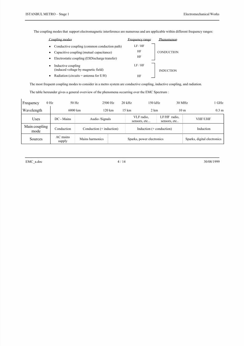
The most frequent coupling modes to consider in a metro system are conductive coupling, inductive coupling, and radiation.
The table hereunder gives a general overview of the phenomena occurring over the EMC Spectrum :
Frequency 0 Hz 50 Hz 2500 Hz 20 kHz 150 kHz 30 MHz 1 GHz
Wavelength 6000 km 120 km 15 km 2 km 10 m 0.3 m
UsesDC - Mains Audio /Signals
VLF radio,
sensors, etc...
LF/HF radio,
sensors, etc..VHF/UHF
Main couplingmode
Conduction Conduction (+ induction) Induction (+ conduction) Induction
SourcesAC mains
supplyMains harmonics Sparks, power electronics Sparks, digital electronics
7/18/2019 EMC plan for metro ps
http://slidepdf.com/reader/full/emc-plan-for-metro-ps 5/14
ISTANBUL METRO – Stage 1 Electromechanical Works
EMC_a.doc 5 / 14 30/08/1999
3. OVERALL DESIGN
Some general basic principles were applied in order to provide an “a priori” step to achieve
EMC of the Istanbul Metro System. These principles are related to two topics; first earthing
and cablings, and then equipment selection.
3.1 Earthing and cablings
As regards this topic, an international IEC Standard is taken as reference:
IEC 61000 - 5 - 2 (nov 1997) :
Electromagnetic compatibity (EMC)
Part 5 : Installation and mitigation guidelines,
Section 2 : Earthing and cabling.
This Standard recommends :
3.1.1 Earthing system design
• Multiple, bonded earth electrodes,
• Bonding all exposed metallic parts and connecting them to the earthing
network.
Let us remark that this is an adequate requirement for both EMC and SAFETY.
These measures are actually applied as far as possible for Istanbul Metro by:
• bonding together all the earth electrodes (pits) of the stations,
• bonding and earthing of enclosures, pipes, cable trays, steel structures, etc...
• earthing cables all along tunnels,
•
dedicated earthing belt for special rooms (substations, signalling & telecom
rooms e.g.).
They are illustrated in the drawing G000PS24SD005
Earthing System General Diagram.
3.1.2
Cablings
•
Make Differential Modes circuits compact and keep them close to earthed
elements.
• Keep some distance between conduits for cables of different use:
- Minimum recommended distance : 0.15 m,
- Recommended stacking order :
- power medium voltage-/- power low voltage-/- auxiliary circuits-/-
control-/- measure,
•
Also reduce magnetic field by shielding,
•
Recommended position of slits in cable trays : parallel to the main axis,
• Avoid transverse slits and slits at the corners of the conduits.
7/18/2019 EMC plan for metro ps
http://slidepdf.com/reader/full/emc-plan-for-metro-ps 6/14
ISTANBUL METRO – Stage 1 Electromechanical Works
EMC_a.doc 6 / 14 30/08/1999
These measures are actually applied for Istanbul Metro with:
•
General use of convenient cable trays, kept in electrical continuity at tees, levelchanges, wall penetrations,
• Typical distance of 20 cm between stacked trays, with 15 cm minimum
distance, and with the following stacking arrangement :
- A - High voltage -/- B - Low voltage - Lighting -/
- C - Control/Telecom/Fire detection -/
- EC - Emergency Control/PA/Emergency telephone.
•
Shielding of MV power cables and control cables dedicated to measurement.
Site checking sheets showing the verification of the minimum distance betweencable trays are gathered in Appendix 1. Moreover, Appendix 2 presents some
examples of basic design drawings that demonstrate convenient principles
application.
3.2 - Equipment
Istanbul Metro takes benefit from European regulation about EMC since critical
equipment supplied for the project are able to be sold within European market.Consequently, they are developed according to the European Council Directive
89/336/CEE (03/05/1989) related to electromagnetic compatibility (and modified
by Directive 92/31/CEE dated 28/04/1992).
This implies series of tests have been yet carried out on the equipment according
to suitable EMC Standards.
Reference to these Standards will be detailed further and samples of compliance
certificates are gathered in Appendix 3
4. EMC ACHIEVING
The measures detailed in the preceding part aims to provide an “a priori” guarantee for
reaching EMC. Nevertheless, it is necessary, as a second step, to carry out a specific
analysis of the electromagnetic interference’s likely to occur in the Metro System and to
check in detail that all the suitable countermeasures have been taken. The key-issue of this
analysis is the disturbance matrix, putting together disturbing and disturbed sub-systems, the
lists of which are the following:
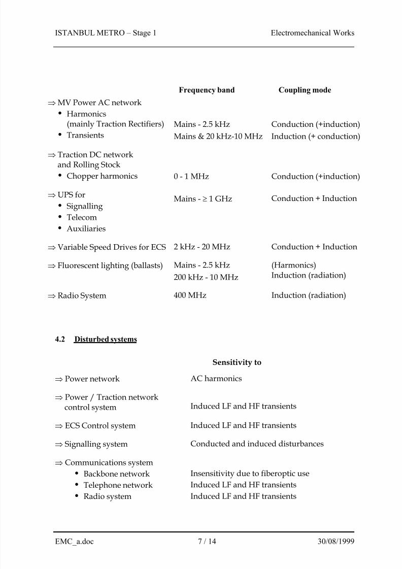
4.1 Disturbing systems
7/18/2019 EMC plan for metro ps
http://slidepdf.com/reader/full/emc-plan-for-metro-ps 7/14
ISTANBUL METRO – Stage 1 Electromechanical Works
EMC_a.doc 7 / 14 30/08/1999
Frequency band Coupling mode
MV Power AC network
•
Harmonics(mainly Traction Rectifiers)
•
Transients
Mains - 2.5 kHz
Mains & 20 kHz-10 MHz
Conduction (+induction)
Induction (+ conduction)
Traction DC networkand Rolling Stock
•
Chopper harmonics 0 - 1 MHz Conduction (+induction)
UPS for•
Signalling
•
Telecom
•
Auxiliaries
Mains - 1 GHz Conduction + Induction
Variable Speed Drives for ECS 2 kHz - 20 MHz Conduction + Induction
Fluorescent lighting (ballasts) Mains - 2.5 kHz
200 kHz - 10 MHz
(Harmonics)Induction (radiation)
Radio System 400 MHz Induction (radiation)
4.2 Disturbed systems
Sensitivity to
Power network AC harmonics
Power / Traction networkcontrol system Induced LF and HF transients
ECS Control system Induced LF and HF transients
Signalling system Conducted and induced disturbances
Communications system
•
Backbone network
•
Telephone network
•
Radio system
Insensitivity due to fiberoptic use
Induced LF and HF transients
Induced LF and HF transients
7/18/2019 EMC plan for metro ps
http://slidepdf.com/reader/full/emc-plan-for-metro-ps 8/14
ISTANBUL METRO – Stage 1 Electromechanical Works
EMC_a.doc 8 / 14 30/08/1999
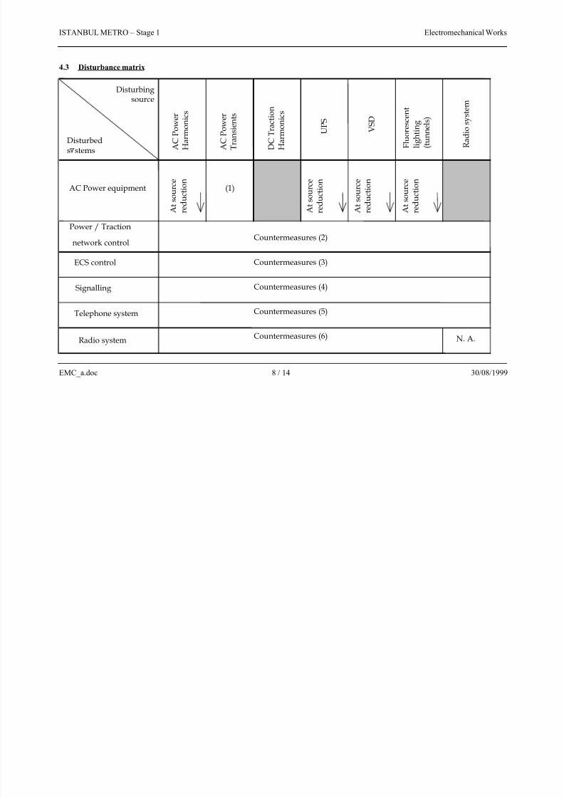
4.3 Disturbance matrix
Disturbeds stems
Disturbingsource
A C
P o w e r
H a r
m o n i c s
U P S
V S D
F l u
o r e s c e n t
l i g h t i n g
( t u n n e l s )
R a d i o s y s t e m
AC Power equipment
A t s o u r c e
r e d u c t i o n
(1)
Power / Traction
network control Countermeasures (2)
ECS control Countermeasures (3)
Signalling
Telephone system Countermeasures (5)
Countermeasures (6) N. A.
Countermeasures (4)
Radio system
A t s o u r c e
r e d u c t i o n
A t s o u r c e
r e d u c t i o n
A t s o u r c e
r e d u c t i o n
A C
P o w e r
T r a n s i e n t s
D C
T r a c t i o n
H a r
m o n i c s
7/18/2019 EMC plan for metro ps
http://slidepdf.com/reader/full/emc-plan-for-metro-ps 9/14
ISTANBUL METRO – Stage 1 Electromechanical Works
EMC_a.doc 9 / 14 30/08/1999
This matrix not only shows the possible interference’s, but also refers, where applicable, to
the measures that are taken to avoid them. These measures classically derive from two basic
principles:
1)
At source reduction,2)
Immunity increasing.
Moreover, in addition to these ones, particular attention was paid to critical equipment
installation by applying geographical segregation.
The detail of these measures is as follows:
4.4 Countermeasures
4.4.1 At source reduction means :
AC Power harmonics : use of 12 - pulse rectifiers allows reduction of half of theharmonics ranks (5, 7, 17, 19, etc...).
AC Power transients : shielding of all MV cables, with screens earthed at both ends.
(induced)
UPS : equipped with input filters compliant with VDE 0871 – A,compliant with EN 50091 - 2 : EMC requirements for UPS.
VSD :
Alspa GD 3000 E drives comply with EN 61800 - 3 (standard product). Alspa C 80 - 35 PLC’s comply with EN 55011 = CISPR 11.
Fluorenscent lighting : electronic ballasts equipped with filters to comply with
EN 55015 = CISPR 15 : limits and methods of measurement of
radio disturbances of electrical lighting equipment and
EN 61000 - 3 - 2 = IEC 61000 - 3 - 2 : EMC - limits for harmonic
current emissions (input current 16 A / phase).
Radio System : compliant with ENV 50121 Parts 3 and 4 for emission criteria.
Please refer to the specific “Radio System EMI/EMC Test Plan”,document number G000XXXXXX
4.4.2 Immunity measures :
( figures in parenthesis refer to the disturbance matrix)
AC Power equipment are designed to withstand power transients(BIL, surge arrestors, etc...).
Power / Traction network control :
PLC’s comply with ENV 50121-5 and EN 61131-2 (CE mark), Cablings are installed according to recognised methods
(cf. “Earthing & Cablings” description).
7/18/2019 EMC plan for metro ps
http://slidepdf.com/reader/full/emc-plan-for-metro-ps 10/14
ISTANBUL METRO – Stage 1 Electromechanical Works
EMC_a.doc 10 / 14 30/08/1999
ECS control :
Alspa GD 3000 E drives comply with EN 61800 - 3 (Product Standard) (CE mark),
Alspa C80-35 PLC’s comply with IEC 61000-4-2, 4-3, 4-4, 61000-6, 255-4, Cablings are installed according to recognised methods
(cf. “Earthing & Cablings” description).
Signalling equipment in tunnel :
On board ATC complies with the EN 50081-2 & EN 50082-2,
Cablings are installed according to recognized methods
(cf. “Earthing & Cablings” description).
Some supplementary precautions are necessary in relation to this critical matter being
the interference of DC chopper harmonics on Signalling System. Therefore, site EMC
measurement are forecast to be performed for the track circuits. They are detailed in thespecific document G000XXXXXX.
Telephone System :
PABX complies with EN50082 : generic immunity standard,
All cablings are shielded with screens earthed at both ends.
Radio System : Equipment comply with ENV 50121 Parts 3 and 4 for immunity criteria.
Please refer to the specific “Radio System EMI/EMC Test Plan”,
document number G000XXXXXX for further details.
4.4.3 Geographical segregation
Even if perturbations due to disturbing equipment are limited while sensitivity of
disturbed equipment are decreased, care has been taken to locate them as far as
possible from each other.
This segregation is made particularly as regards :
Extra Low Voltage (ELV) equipment which includes mainly the PLC ’s,
the computers, the signalling and the telecom ones as disturbed equipment.
the MV-DC-LV(high power)-UPS-VSD as disturbing equipment.
It applies in the following typical locations:
- TPS-LPS : Power equipment
(MV-LV-DC)+ UPSELV equipment
- Ventilation rooms : LV power equipment
(including VSD)ELV equipment
- CCR/CER, Signalling/Telecom rooms : UPS ELV equipment
As regards SOR, these precautions do not apply since they only include low power
supply feeded in L.V.
7/18/2019 EMC plan for metro ps
http://slidepdf.com/reader/full/emc-plan-for-metro-ps 11/14
ISTANBUL METRO – Stage 1 Electromechanical Works
EMC_a.doc 11 / 14 30/08/1999
5. CONCLUSION
This document points out that EMC of Istanbul Metro has been controlled during the
Project. All necessary and adequate measures have been taken, and convenient site tests are
forecast in order to finally ensure the required quality and performance of the System.
7/18/2019 EMC plan for metro ps
http://slidepdf.com/reader/full/emc-plan-for-metro-ps 12/14
ISTANBUL METRO – Stage 1 Electromechanical Works
EMC_a.doc 12 / 14 30/08/1999
APPENDIX 1
Site checking sheets related to cable stacking interval
( En attente )
7/18/2019 EMC plan for metro ps
http://slidepdf.com/reader/full/emc-plan-for-metro-ps 13/14
ISTANBUL METRO – Stage 1 Electromechanical Works
EMC_a.doc 13 / 14 30/08/1999
APPENDIX 2
Examples of basic design drawings related to EMC
7/18/2019 EMC plan for metro ps
http://slidepdf.com/reader/full/emc-plan-for-metro-ps 14/14
ISTANBUL METRO – Stage 1 Electromechanical Works
EMC a doc 14 / 14 30/08/1999
APPENDIX 3
Samples of EMC compliance certificates