Embed Size (px)
Citation preview

www.divecochran.com
Cochran EMC-14
Owner's Manual
English - Imperial Ver: EMC-14i - 1.00
For your records, please fill in the following:
Serial Number: _________________________ Your Name: ____________________________ Your Contact:___________________________ ______________________________________ ______________________________________ Purchase Date: _________________________ Purchase Place: ________________________ Address: ______________________________ ______________________________________ ______________________________________


1
PRODUCT INTRODUCTION: The EMC-14 is quite simple to use and operate, but underneath that simplicity lies a significant level of sophistication. To get the safest and most effective use of this instrument, it is important that the user fully understand the product. Please read and understand this entire manual and know the principles and practices of safe diving before using this device. If you are using the EMC-14 with the Nitrox functions enabled, the diver specifically acknowledges that he has been adequately and thoroughly trained and certified to engage in Nitrox diving by a professional, competent, recognized training agency.
This Manual is divided into the following Sections: Section Page • Operation 1 • Clock Operation 4 • Touch Programming 5 • Warnings 7 • Oxygen & PO2 factors 7 • Configurable Items 9 • Specifications and Maintenance 10 • Liability, and Warranty 11 • Itemized Index and Subjects 13
TOUCH CONTACTS:
The Contacts are used to let the user command the unit to do a number of functions, communicate with a PC for extracting information or configuring the unit, and determining water conductivity. When Contacts 1 & 2 are shorted, the EMC-14 can detect the difference between wet fingers, metal objects, fresh water, salt water, and a PC interface probe.
TURNING ON THE EMC-14: Although the EMC-14 automatically turns on when it is submerged in water, it is STRONGLY recommended that the unit be manually powered up by simultaneously touching Contacts 1 and 2 for two seconds with two wetted fingers. This allows the diver to ensure that the unit is operating correctly and has adequate battery capacity prior to entry. Once activated, the unit will remain on for 60 minutes. If a dive is not initiated within these 60 minutes, the EMC-14 automatically shuts off. Every time Contacts 1 & 2 are bridged with wet fingers, the unit will stay on for one full hour.
The EMC-14 will not turn on if the altitude is greater than 16,000 feet or if the battery voltage is less than 1.6 volts, or a fault is detected during the self-test.
As the EMC-14 first recognizes a turn-on command, it begins a “Diagnostic” function where many aspects of the system will be exercised and tested. This procedure takes about five seconds. During this time, all of the segments in the display are turned on so that the user can confirm their operability. Should a test indicate a malfunction or marginal test, the unit will turn back off again. The user should ensure that all of the display segments are on and operating correctly.
TURNING OFF THE EMC-14: After the Post Dive Interval following a dive, the EMC-14 will remain on for one hour before automatically entering its "Sleep Mode". During the Sleep Mode, all calculations continue but the display is off. This is a power saving feature of the EMC-14. The unit will continue calculating Surface Interval, compartment off gassing as required, and any changes in altitude as it affects Nitrogen Loading. The current Surface Interval and PreDive Predictions can be viewed by reactivating the unit MAIN EMC-14 OPERATING MODES: • Surface Interval (No Nitrogen Residual) • Surface Interval (With Nitrogen Residual) • Dive Mode (Normal No Deco) • Decompression Mode • Post Dive Interval • Touch Programming
SURFACE INTERVAL:
After completion of the Self-Diagnostic mode or after the Post Dive Interval following a dive, the EMC-14 enters the Surface Interval. This period has two screens, a Primary and an Alternate. The Primary and Alternate screen alternate ever four seconds, this cycle time is settable via Analyst®. The Primary Screen displays, if applicable; current Surface Time, the previous dive’s Maximum Depth, the previous dive’s Bottom Time, Dive of Day number, current Time to Fly, Altitude and Temperature. The Alternate Screen displays current calculated CNS, time of day (alternates with current calculated OTU), and current battery voltage. Figure 2 shows the display with no residual Nitrogen (a clean Dive). Figure 4 shows the display with residual Nitrogen (a repetitive dive). Figure 5 shows the alternate screen without residual Nitrogen, figure 6 with.

2
“Surface Time” starts at zero after a dive and begins counting minutes. If the computer shuts off (enters the sleep mode) and is turned on with Nitrogen residual left, the Surface Time continues to count. If the computer shuts off (enters the sleep mode) and is turned on with no Nitrogen residual, the Surface Time will be zero. “Dive of Day” starts at zero and increments after each dive regardless of the calendar day. When there is no remaining Nitrogen residual, the Dive of Day is set to zero and the computer is referred to as a ‘clean’ system. “Time to Fly” is displayed as the number of hours remaining until the nitrogen residual reaches zero plus a twelve-hour safety factor. Flying is not recommended until Time to Fly reaches zero.
“Barometric Altitude” is indicated in six ranges via the Ascent Rate Bar Graph as follows (Altitude compensation is seamless up to 16,000 feet above sea level). The six ranges are for display purposes only: The EMC-14 actually senses and computes extremely small altitude changes and hence, is called “Seamless”. The term “Barometric Altitude” is used instead of just “Altitude” because the EMC-14 measures Barometric Pressure to determine Altitude. Barometric Altitude can vary from actual Altitude by over +/- 1000 feet! Barometric Altitude is what important to the body when diving.
DIVE MODE: Whether in the Surface Interval, PreDive Prediction Mode, Programming Mode or the Logbook Mode, the EMC-14 will automatically enter the Dive Mode whenever the unit determines that it is in water deeper than five feet. On the Primary Screen the Surface time will be replaced with the current Bottom Time. Maximum Depth will be replaced with current Depth, displayed in one-foot increments. Bottom Time will begin once the EMC-14 senses that the diver has descended below five feet and continues until the diver has ascended above three feet. The maximum Bottom Time displayed is 19 hours 59 minutes.
The Alternate Screen will display the current FO2 value that the unit is using in its NDC calculations, the current CNS and OTU values, the current battery voltage and the Max Depth (so far this dive). (Figure 7)
A Depth Alarm, which can be set to warn the diver should a certain depth be exceeded, is set at 130 feet from the factory. When the Depth Alarm is issued the “WARNING” legend and Depth Digits will flash on and off once per second. The depth alarm is disabled if in the Decompression Mode since flashing depth digits have another meaning in this Mode. The maximum depth achieved on the current dive is shown as “MAX DEPTH”. This is updated once per second. “REMAIN TIME” (NDC) is the remaining time (in hours and minutes) that the diver can stay at the current depth without requiring decompression.

3
A “Two Minute Warning” will be issued when this time reaches two minutes or less. The “WARNING” legend and “REMAIN TIME” digits will flash. By immediately ascending to a shallower depth, the diver may avoid a required decompression stop. Temperature is measured for two purposes. One is to compensate the Depth Transducer for Temperature variations. The other is to compensate the Nitrogen algorithm for changes in Temperature that may affect the body. Both of these purposes require that the Temperature be very slow reacting, just like the Depth Transducer and the body. This slow-reacting Temperature is what is displayed. For Temperature effects on the body, the amount of compensation can be set from NORMAL to REDUCED with the Analyst® PC software Interface (see Analyst® Section), if the diver is using a good dry-suit in cold water. Temperature compensation starts at 75 degrees F and gets progressively more conservative as the temperature decreases. There is no compensation above 75 degrees F. Bottom Time will begin once the EMC-14 senses that the diver has descended below five feet (see Training Mode) and continues until the diver has ascended above three feet. The maximum Bottom Time displayed is 9 hours 59 minutes.
ASCENT RATE BAR GRAPH: The Ascent Rate bar graph and alarms are active in both the Dive Mode and Decompression Mode. The five-segment bar graph is used to display the diver's rate of ascent. Via the Analyst® PC Interface, the Ascent Rate Alarms and Bar Graph can be set to the users preferences. The first option is a VARIABLE-BY-DEPTH Ascent Rate. When on, the Ascent Rate Alarm is determined by depth. As the diver ascends to shallow depths, the Maximum Ascent Rate is lowered. The Maximum Ascent Rates and their associated depth are:
60 feet or deeper 60 feet per minute 60 to 30 feet feet per minute equal to the depth Less than 30 feet 30 feet per minute
If VARIABLE-BY-DEPTH is off, the Maximum Ascent Rate Alarm and Bar Graph is specified by the user and can be from 20 to 60 fpm, in one-foot increments. Another selection is the bar graph itself. The two selections are either FIXED or PROPORTIONAL. With FIXED, each of the five bars indicates an additional 10 feet per minute of Ascent Rate regardless of the Maximum Ascent Rate selected. With PROPORTIONAL, each of the five bars indicates 20% (one-fifth) of the selected Maximum Ascent Rate. For FIXED, the maximum ascent rate is 60 feet per minute. With this setting, no bars will illuminate if a diver is ascending at a rate less than 10 feet per minute.
If the diver has an Ascent Rate that exceeds the selected maximum, the entire Ascent Rate Bar Graph will flash once per second, and the WARNING legend will illuminate. The sensitivity or responsiveness of the Ascent Rate may be selected via the Analyst®, eight different levels of sensitivity are available. NOTE: Customizing the Ascent Rate and Ascent Rate Bar Graph are among many of the additional programmable features available when using the Analyst® PC Interface. Available features are described in the section “USER CONFIGURABLE OPTIONS”.
As shipped from the factory, the Ascent Rate is set for VARIABLE-BY-DEPTH AND PROPORTIONAL.
DECOMPRESSION MODE:
Should a no-decompression limit be overstayed, the EMC-14 will enter the Decompression Mode. In this mode, the Ceiling digits will display the depth at which the diver must stop and not ascend above during final ascent. The “TEMP” legend and two digits will be replaced with the “CEIL” legend and two digits. The Ceiling will start at 10 feet and increase in ten-foot increments as the diver remains at a relatively deep depth.
The Remaining No-decompression Time and “NDC” legend will be replaced with Decompression Time and “DEC” legend (Figure 16d). Both STOP time and TOTAL time are displayed in the lower three digits of the screen in hours and minutes. STOP and TOTAL time will alternate at the rate of once every two seconds. In this way, the diver can view the time to spend at a particular STOP depth, and the TOTAL time it will take to complete all STOPS. Clearly, the larger of the two alternating numbers is the Total Decompression Time of all stops, and the smaller of the two numbers is the time required at the current stop. At the ten-foot stop, the TOTAL and STOP times may be the same and therefore appear to not alternate.
When at a specific stop, the required decompression time at that stop is as shown, and will appear to count down as it is recomputed every second, based on the divers exact current depth. The Decompression times (both Stop and Total) are accurate only if the divers’ depth is exactly the same as the required Ceiling. However, it is not necessary to be precisely at that specified Ceiling. Appropriate In-gassing or Out-gassing will be computed regardless of the divers’ current depth.

4
A small margin shallower than the Ceiling also exists. Should a Ceiling be ‘violated’ (diver is shallower than Ceiling), the “WARNING” legend will illuminate and flash along with the Depth and Ceiling digits. This warning will continue until the Depth has been corrected. Out-gassing will continue even though the diver is shallower than the Ceiling. There is no ‘Gauge’ mode or ‘Lockout’ on the EMC-14. If the diver surfaces before satisfying his decompression obligation, the EMC-14 will continue to give out-gassing credit as if it were in a dive, but at a depth of zero feet and will satisfy the decompression time requirements of the required stops using an FO2 of 21%. The unit will continue to log data and perform as if actually in a dive. When the decompression obligation is finally satisfied, the ten-minute “PostDive Interval” will begin.
NOTE: COCHRAN does not intend for this instrument to be used for deliberate Decompression diving. POST DIVE INTERVAL: During the first ten minutes (or up to thirty minutes if the unit is in the Training Mode) after a dive, the EMC-14 is in the Post Dive Interval. The flashing "SURF" legend and a Surface Time of less than ten minutes (or up to thirty if the unit is in the Training Mode) indicate this. Should another dive be commenced before the completion of the Post Dive Interval, that dive will be considered an extension of the previous dive. In this case, Bottom Time will NOT include the time spent on the surface in this Post Dive Interval. However, when reviewing the profile with the Analyst®, the time spent on the surface in this period will be shown.
CONFINED WATER PROTOCOL (Training Mode): The EMC-14 is one of the first dive computers to offer an operating mode designed to record and store data from training dives. That is, dives performed in shallow water environments (swimming pools, shallow lakes, lagoons, etc.) or calm open water environments that have less than 1-foot seas. In the Training Mode, the EMC-14 enters the Dive Mode at a depth of 2 feet instead of 5 feet and will exit the Dive Mode at 1 foot instead of 3 feet. Also the Post Dive Surface Interval may be extended, via the Analyst® from10 minutes up to a maximum of 30 minutes in 1-minute increments after which the dive data is stored in the computer's memory. These changes permit the Instructor to record the complete training session, including in-water surface periods, as a single dive. The Training Mode can only be enabled/disabled via the Professional Edition of the Analyst® PC Interface. CLOCK MODE: The Clock operating mode of the EMC-14 is NOT enabled when shipped from the factory. It can be enabled via the Analyst® P.C. Interface or at an Authorized Cochran Dealer. TOUCH PROGRAMMING MODE: Can only be accessed when the unit is in the Surface Interval and allows the user to view or program into the dive computer:
• Setting Date Clock Time • The PreDive Prediction Mode • Displaying Mode, mode value, CNS, OTU & battery voltage • A Maximum Depth Alarm • An Added degree of Conservatism from 0 to 50% • Setting oxygen percentage of blend 1 in the Constant FO2 Mode • Access the Logbook Mode
While all EMC-14 configurations share certain programming features others are dependent upon the specific configuration of the unit. Refer to the appropriate manual section for the relevant programming menu items.
TOUCH PROGRAMMING - CLOCK: When the EMC-14 is placed into the Clock mode it will display the time of day in an am/pm day format. The clock will continue to run when the EMC-14 is in the Dive Computer Mode. The EMC-14 can be placed into the Clock Mode from the Dive Computer Mode when the unit is in the Normal Surface Interval, while the unit is in Clock Mode the Dive Computer will be in the “Sleep” mode.
NOTE: This Time of Day clock is the same clock that is used to time stamp dives. Modifying the Time of Day clock and/or the Date will affect the Local Time/Date as viewed via the Analyst®.
CLOCK PROGRAMMING PROCEDURE: To begin the programming sequence: 1. Turn the unit on; 2. Using a coin or other conductive metal object, briefly bridge
Contacts 1 and 2 until the CLoCk Menu is seen on the display (fig 30).
3. To enter the Clock submenu, bridge Contacts 1 & 2 with wetted fingers. This will cause the unit to display the CLoCk dAte selection (fig 31).
4. Using a coin or other conductive metal object, bridge Contacts 1 & 2 to access the month of the CLoCk Date setting screen fig 32.
5. Bridge Contacts 1 & 2 with wetted fingers. This will cause the months tens digit to flash.
6. Shorting Contacts 2 & 3 with a coin will increment the numeric value; continue until the required value is displayed.
7. Next using wetted finger, bridge Contacts 1 & 2 to select the next digit; once selected the digit will flash to identify that it is being programmed. Bridge Contacts 2 & 3 till the desired value is displayed.
8. To select the Day short Contacts 1 & 2 with a coin, increment as in step 6 and 7 (fig 34).
9. Repeat step 5 through 7 until all digits have been programmed. 10. To select the Year short Contacts 1 & 2 with a coin, increment as in
step 6 and 7 (fig 33). 11. Repeat step 5 through 7 until all digits have been programmed. 12. To set the Time short Contacts 1 & 2 with a coin, increment as in
step 6 and 7 (fig 40). 13. Repeat step 5 through 7 until all digits have been programmed. 14. To save the changes that have been made and to enter the Clock
Display Mode, bridge Contact 1 & 2 with a coin or other conductive metal object. Once the next programming option is displayed the changes have been saved.

5
To exit the Clock Mode Bridge contacts 1 & 2 with wetted fingers and the computer will return to the Dive Computer Mode’s Surface Display. NOTE: Ensure that the EMC-14 is in the Dive Computer Mode before
commencing a dive. Figures 30, 31, 32, 33, 34 and 41 show how the Clock programming display screens appear.
Figure 40 shows how the Clock display screen appears.
NOTE: Once the EMC-14 is placed in Clock Mode the unit will remain
in that mode until exited by the diver. TOUCH PROGRAMMING MODE: NOTE: To enable the Programming Mode, the EMC-14 must be on
the Surface and not in the Post Dive Interval. NOTE: All visual alarms are suspended while the EMC-14 is in the
Programming Mode. Upon exiting the Programming Mode all alarms are reactivated.
NOTE: Once a value has been changed and the next menu option selected, the new value is stored.
NOTE: It is strongly recommended that the Programming Mode is activated again and what was stored is reviewed.
NOTE: If the EMC-14 is left in the Programming mode for five minutes without the contacts being touched, the unit will automatically exit the Programming Mode and return to the Surface Interval. Once this occurs the EMC-14 will retain the modified programmed settings but options that have not been modified will retain their current settings.
TOUCH PROGRAMMING MODE - PROCEDURE: Contacts 1, 2, & 3 are for programming sequences. To begin the programming sequence: 1. Analyze the gas blend using a calibrated Oxygen Analyzer. 2. Turn the unit on. 3. Using a coin or other conductive metal object, briefly bridge Contacts
1 and 2 until the Programming Menu is seen on the display. The Programming Menu options depend on whether the unit is activated for Clock, and /or Nitrox. The Menu options are displayed in sequence, incrementing to the next selection each time that Contacts 1 & 2 are bridged with a coin. The program option is displayed on the upper row of the display. The current setting for this option is displayed in the lower right of the display.
4. To reprogram the displayed menu values, bridge Contacts 1 & 2 with wetted fingers. This will cause the current setting to flash or in the case of multi-digit numbers, the least significant digit will flash. The clock will toggle between on and off.
5. Using a coin or other conductive metal object, bridge Contacts 2 & 3 to increment the numeric value. Next using wetted finger, bridge
Contacts 1 & 2 to select the next digit, once selected the digit will flash to identify that it is being programmed. Bridge Contacts 2 & 3 till the desired value is shown.
6. Repeat step 5 until all digits have been programmed. 7. To save the changes that have been made bridge Contact 1 & 2 with
a coin or other conductive metal object. Once the next programming option is displayed the changes have been saved.
All programming sequences use the same routine of using Contacts 1 and 2 to SELECT the next programming sequence and Contacts 2 and 3 to INCREMENT the specified value. PROGRAMMING MENU - Air Only: The following table lists the various programming choices with their display identification and figure number.
Identification Description Figure Page
CLC Clock – if enabled 30 5 PdP PreDive Prediction 12 8 InF Misc. Information 14 8 dEP AL Depth Alarm, Max value
is 180 or 320 feet 16 8 (Depending upon unit configuration)
Con Added Conservatism, Max value is 50%. 18 8
LOG Logbook 24 8 PROGRAMMING MENU - SINGLE GAS NITROX The following table lists the various programming choices with their display identification and figure number.
Identification Description Figure Page
CLC Clock – if enabled 30 5 PdP PreDive Prediction 12 8 InF Misc. Information 14 8 dEP AL Depth Alarm, Max
is 180 or 320 feet 16 8 (Depending upon unit configuration)
Con Added Conservatism, Max allowed value is 50%. 18 8
EAn 1 Oxygen percentage of Blend, Allowed value 21 to 50 20 8
LOG Logbook 24 8 TOUCH PROGRAMMING - PREDIVE PREDICTION:
PreDive Prediction is accessed via the Touch Contact Programming Menu. This enables the diver to view the PreDive Prediction information at the touch of the Contacts. The EMC-14 PreDive Prediction starts at 30 feet and increases in 10 feet increments. PreDive Predictions will terminate when the No-Decompression (NDC) time prediction reaches two minutes or a maximum depth of 180 or 320 feet (depending upon unit configuration) is reached. Additional Conservatism, Residual Nitrogen, blend #1 oxygen percentage and Barometric Altitude can affect PreDive Predictions. Once the maximum PreDive Prediction depth has been reached the unit will return to the Surface Interval. During the PreDive Prediction Mode, the unit will compute and display the maximum safe time and the calculated PO2 value at that depth.

6
TOUCH PROGRAMMING - INFORMATION DISPLAY:
The InFormation display is accessed via the Programming Mode. The information presented will depend on the configuration of the dive computer. The information in the lower middle of the screen indicates whether unit is in the Constant FO2 (Nitrox) or Air Mode. The following table lists the identification and the description.
Identifier Description F0 Air only F1 Single Blend Nitrox, 21 to 50%
Battery voltage is displayed in the middle right center of the screen as a two-digit number with an implied decimal point. If the unit is configured for Constant FO2 (Nitrox), the screen will display the current CNS, along with the Time of Day and battery voltage. The current CNS exposure level is displayed on the middle left as a two-digit number proceeded by a lower case “c”. The current time is displayed in the middle center. The CNS value is expressed as percentages. Figure 24a displays a typical InFormation screen for a unit that is enabled for Nitrox. TOUCH PROGRAMMING - DEPTH ALARM: The Depth Alarm allows the diver to select a maximum depth below which the diver does not wish to descend before an alarm is issued. This depth can be set from 0 to 180 or 320 feet in one-foot increments (depending upon unit configuration).
TOUCH PROGRAMMING - CONSERVATISM: This programming function allows the diver to input an added degree of Conservatism into the EMC-14 algorithm. Via Touch Programming the Conservatism can be set from 0 to 50%.
TOUCH PROGRAMMING - BLEND #1: The oxygen percentage of Blend #1 can be programmed from 21.0% to 50.0%. Once programmed the oxygen percentage will remain at the value programmed until changed by the user.
TOUCH PROGRAMMING - LOGBOOK MODE: The Logbook of the EMC-14 has two screens, a Primary Screen and an Alternate Screen. The Logbook is accessed via the Touch Contact Programming (see page 15). This enables the diver to view dive statistics; the EMC-14 has the ability to provide diving data for the most recent 256 dives. The most recent dive will be displayed first. To view the next dive, touch the contacts 1 & 2 with wetted finger after pausing for a few seconds. Do not use a metal object such as a coin or knife-blade once in the Logbook since it will cause the unit to exit the Logbook and return to the Surface Interval. Information contained in the Logbook include: Overall Dive Number Minimum NDC Time Fastest Rate of Ascent Minimum Water Temperature Bottom Time Surface Interval Before Dive Maximum Depth Ending Battery Voltage Maximum DEC Time (Deco Dive) Maximum Ceiling (Deco Dive) The Dive Number that is displayed on the Logbook Menu screen (Figure 25) permits the diver to identify the number of dives made with that EMC-14. If the example shown is the most recent dive made, it can be identified that 136 dives have been made with this unit.
Figure 26 shows that dive 136 started at 10:18 AM on the 8th of October 2003.

7
Figures 27 & 28 display the Logbook of a Normal Dive.
While Figures 29 & 29A display that of a Deco Dive
WARNING INDICATIONS: Failure to observe visual warnings and take corrective action may result in injury or death. In general, if the WARNING legend is flashing, some other digits should be flashing to indicate the anomaly.
• If the diver is ascending faster than the selected maximum ascent rate, then the top bar of the ascent bar graph will flash and the “WARNING” legend will illuminate.
• If the diver descends below the user set Depth Alarm, the Depth digits will flash. The Depth alarm is not active in the Decompression Mode to avoid confusion with the “Shallower Than Ceiling” alarm.
• If the battery voltage goes below 2.4 volts, the “BATT” legend will begin to flash on and off once per second.
• If the diver has less than two minutes of No-Decompression Time (NDC) remaining, the “WARNING” legend will illuminate and flash along with the Remaining NDC time digits.
• During a Decompression dive, if the Depth is less than the CEILING, the “WARNING” legend will illuminate and flash along with the Depth and Ceiling digits.
• If the dive computer determines that either the Depth or Temperature sensor is malfunctioning. The “WARNING” and "SENSOR" legends will illuminate, The Screen will also display either "DEPTH" and/or "TEMP".
• For High PO2, see “OXYGEN TOXICITY FACTORS” on page 7.
• For High CNS, see “OXYGEN TOXICITY FACTORS” on page 7. SENSOR WARNING: The EMC-14 has the capability of monitoring the integrity of it’s' sensors, both the low-pressure (depth/altitude) and the temperature. When the computer detects an error in one of the transducers, the diver is alerted to this condition by the illumination of the “WARNING” and "SENSOR" legends The "DEPTH" Legend will illuminate to indicate the low-pressure transducer or the "TEMP" legend for the temperature transducer (see figure 18a). The “WARNING” legend, along with either the Temperature digits or the Depth digits and the Legend will flash once per second. In the highly unlikely situation were both sensors are detected as having errors, both the "DEPTH" and "TEMP" legends will illuminate. This warning will be issued whether the computer is in the Surface Interval, Dive Mode, Decompression Mode or Post Dive Interval. In the unlikely case that your computer issues one of these warnings the unit should be returned to the factory for evaluation and/or repair. Figure 39 shows a Sensor Warning, in this case a Depth Sensor, as it would be displayed in the Dive Mode. If the Sensor Warning was for the temperature sensor it would display "TEMP“.
OXYGEN TOXICITY FACTORS: The EMC-14 has the ability to track Oxygen Toxicity levels for the Central Nervous System (CNS) as well as the Mission Oxygen Tolerance Units Dose (OTU). In addition, a maximum Partial Pressure of Oxygen (PO2) warning alarm can also be set.
As long as one or more of these three parameters is outside its limits, the “WARNING” legend on the display will continue to flash. These three functions are not active if the NITROX capability is disabled via the Analyst® PC Interface. PARTIAL PRESSURE OF OXYGEN (PO2): High levels of PO2 can cause severe Oxygen poisoning. Widely different levels of PO2 can affect individual divers. The user via the Analyst® can set the PO2 alarm to any level between 0.50 ATA and 1.59 ATA. As shipped from the factory, this is set to 1.40 ATA. Should the PO2 be above the alarm set point, the “WARNING” legend will illuminate and the displayed PO2 value will flash.

8
CENTRAL NERVOUS SYSTEM (CNS) TOXICITY: By the accepted definition of CNS toxicity, should a PO2 value of greater than 1.6 ATA be measured; the CNS Toxicity will be 100%. During the Surface Interval, this percentage will decrease as the CNS declines toward zero. Whatever the current CNS Toxicity level, it can also be viewed on the Surface Interval Alternate Screen or on the InFormation screen in the Programming Mode. The user via the Analyst® can set the CNS Toxicity alarm to any level between 40% and 80% of the maximum allowable limit. As shipped from the factory, this is set to 50%. Should the CNS Toxicity reach 50% of the maximum allowable, the “WARNING” legend will illuminate and on the Alternate Screen the displayed CNS percentage will be flashing along with the “WARNING” legend.
OXYGEN TOLERANCE UNITS (OTU): An issue with long term breathing of higher partial pressures of Oxygen above 0.5 ATA is Pulmonary Oxygen Toxicity or sometimes called WHOLE BODY which must be tracked properly. The EMC-14 will track OTU based on Dr. Bill Hamilton’s ‘REPEX’ method of oxygen exposure management. The OTU Dose is an exponential function of oxygen partial pressure and time. The time-dependent limit varies with length of time (days) that the diver continues to dive without full recovery to zero OTU. The Mission OTU Clock tracks the OTU, which is a running clock that tracks long-term Oxygen exposure. This clock may run for several weeks if frequent dives are made using high levels of PO2. The recovery portion of the OTU algorithm is a linear reduction of OTU over time. The Mission OTU clock is reset to 0:00 when the OTU Dose reaches zero. Symptoms of Pulmonary Oxygen Toxicity include burning in the throat and chest, coughing, and shortness of breath. Discontinue diving and consult a Physician should any of these, or other, symptoms appear. The current Mission Clock, CNS, and OTU values can be seen via the Analyst® PC interface or the current CNS and OTU values can be viewed on the Alternate Screen while in the Surface Interval, Dive Mode, Decompression Mode or Post Dive Interval. The current CNS and OTU values can also be viewed via the Touch Contact Programming mode by selecting the InFormation option. The user via the Analyst® can set the OTU Toxicity alarm to any level between 40% and 80% of the maximum allowable limit. As shipped from the factory, this is set to 50%. Should the OTU Dose reach 50% of the maximum allowable, the “WARNING” legend will illuminate and on the Alternate Screen the displayed OTU value will be flashing along with the “WARNING” legend. Figure 38 shows a CNS exposure over the alarm set point (50%), in the situation were both the CNS and the OTU exposure was over their set points both values would flash.
TOUCH CONTACT PROGRAMMING SCREENS: The following are all of the screens that the EMC-14 is capable of presenting in the Touch Programming Mode. Refer to the particular configuration for appropriate screens.
DATA STORAGE TYPES & CAPACITY: The EMC-14 has the following internal distinct data storage activities that can be recalled, viewed, and stored with the Analyst® PC computer interface: • Current Variable Information: Local Time, CNS toxicity, OTU
Toxicity, Altitude, Battery voltage, Current unit Temperature, 14 tissues loading, and Time to Fly.
• Current Configuration Data: As can be seen in “USER CONFIGURABLE ITEMS”, below.
• Historical Totals Summaries: Dive Time, Number of Dives, Number of Marginal Dives, Number of Violated Dives, Number of Warnings, Decompression Dives, Decompression Time, Maximum Depth and Ceiling, Maximum Depth and Ceiling Dive Number.
• Each Dive Beginning Statistics: 14 tissues loading, Local Time Clock, Dive of Day, Dive Number, Surface Time, CNS Toxicity, OTU Dose, OTU Mission Clock, Altitude, Time to Fly, Battery Voltage. Capacity is the most recent 256 dives.
• Each Dive Ending Statistics: 14 tissues loading, Bottom Time, Max Depth, Average Depth, Min NDC Time, Max Deco Time, Max Deco Ceiling, Missed Ceiling, Missed Deco Time, CNS Toxicity, OTU Dose, OTU Mission Clock, Max PO2, Max Ascent Rate, Max A/R Time, Max A/R Depth, Min Temperature, Average Temperature, Maximum Temperature, Min Battery Voltage, Time to Fly, number of Warnings. Capacity is the most recent 256 dives.
• Each Dive Configuration Data: Full and complete configuration of the system, including Blend #1 Oxygen %, User Conservatism. Capacity is the most recent 256 dives.
• Profile Graphical Information: Depth Graph, Ascent Rate Graph, Temperature Graph, PO2 Graph, O2 % Graph, CNS Graph and OTU Graph. Capacity is 180 hours at one second sampling (dependent upon memory configuration).
• Inter-Dive Events: Number of Initializations, Unit Activation, Altitude Changes of 500 Feet, Temperature Changes of 10 degrees, Low Batteries, Sensor Malfunction, Analyst® interface with Dive Computer.

9
INTER-DIVE EVENTS: The EMC-14 stores important information between dives, even when the unit is not turned on. The information is stored as acquired and is called an “Inter-Dive Event”. Some Inter-Dive events are:
• Initialization of the unit. • The unit is turned on • Low batteries • Altitude Changes of over 500 feet • Temperature Changes of 10 degrees • Sensor Malfunction • Analyst® P.C. Communication
USER CONFIGURABLE ITEMS: The number of and which configurable options are viewed is determined by the EMC-14’s configuration. Caution: Items that can be changed via Touch Contact Programming may be different from their factory settings. By using the optional Analyst® Personal Computer Interface, the user has the ability to change the following items: Dive Time/date Stamp: This is the internal clock setting that is used by the system to time-stamp each individual dive as it occurs. Due to changes in battery voltage and temperature, the internal Time-of-day clock may slowly drift from the ideal. It is recommended that this clock be periodically set to your local time via the Analyst®. Metric or Imperial: The diver may select whether the data is computed and displayed in Metric or Imperial units. The EMC-14 may be ordered either way as shipped from the factory. Selectable Ascent Rate Bar Graph (Fixed or Proportional): This option determines whether the Ascent Rate bar graph indicates the speed of ascent or the percentage of the selected maximum ascent rate. From the factory this set to ‘Proportional’ (percentage). Selectable Variable-By-Depth Ascent Rate Alarm (On or Off): This option gives the diver the ability to utilize a fixed ascent rate warning or a warning based on depth. Should the diver prefer the fixed ascent rate warning the diver can select the maximum ascent rate limit of from 20 to 60 feet per minute (See next topic). As shipped from the factory, this is set to ON. If the VARIABLE rate is selected then the warning will illuminate based on the following table:
DEPTH AVERAGE ASCENT RATE 60 feet and deeper 60 feet per minute 60 to 30 feet same as depth Shallower than 30 feet 30 feet per minute
Selectable Fixed Ascent Rate Alarm Limit: If Variable-By-Depth Ascent Rate Alarm was set to OFF from the above topic; the user may enter the desired Ascent Rate for the alarm to be issued. Ascent Rate Responsiveness (0 to 7): This option determines the responsiveness or sensitivity of the Ascent Rate Bar Graph. Zero is highly responsive and seven is very slow. This feature is set to three as shipped from the factory Remaining Time Responsiveness (0 to 7): This determines the responsiveness of the Remaining Time information that is displayed. Zero is highly responsive and seven is very slow. This feature is set to three as shipped from the factory Max Depth Alarm: This option allows the diver to select a maximum depth below, which the diver does not wish to exceed before an alarm is issued; this function is disabled when in the Decompression Mode. This option may also be set via the Touch Contact Programming. As shipped from the factory, the Depth Alarm is set for 130 feet. Select Decompression Time Display (Total, Stop, Both): There are three options for the manner in which the decompression time is displayed. If you select TOTAL, the decompression time displayed will indicate the total time you will spend in decompression. Watch the Ceiling depth change in order to identify when to ascend to the next stop depth. If you select STOP, the decompression time displayed will indicate the time you must remain at the current Ceiling. When this time is 0:00, the Ceiling depth will decrease and the new stop time will be displayed. If you select BOTH, the TOTAL time and STOP time will alternate at the rate of once every 2 seconds. From the factory, the unit is set to ‘Both’. Temperature Dependent NDC Computations (Normal or Reduced): This feature compensates the decompression algorithm proportional to the ambient water temperature. See User & Environmental Adaptation,
Water Temperature on page 60 for a detailed description of this function. From the factory with this feature set to ‘Normal’. Select Altitude <2000 feet as One Zone (Off or On): This option provides "actual" altitude for any given day at any diving location as explained in the “ALTITUDE ACCLIMATIZATION” on page 12. With changes in barometric pressure due to temperature and weather systems, it is possible, even expected, to have a different apparent altitude at the same dive site from day to day. While the seamless means of monitoring provides the most accurate decompression schedule, all altitudes less than 2,000 feet above sea level can be treated in the algorithm as sea level if so selected. With this option OFF, the unit is calculating altitude in a seamless fashion. With this option ON altitudes less than 2,000 feet above sea level will be treated as sea level. Regardless of the selection, altitudes greater than 2,000 feet above sea level will be treated in a seamless manner. From the factory, this is set to ‘Off’, seamless altitude from sea level to 16,000 feet. Select Alternate Screen Viewing Time (3 to 10): This option allows the diver to set the amount of time that the Alternate Screen will be viewed. From the factory this is set to 4. Select Ceiling Display Divided by 10 (On or Off): This option allows the diver to select when in the Decompression Mode the Ceilings are displayed as 1 = 10, 2 = 20, 3 = 30 etc. (On) or as 10, 20, 30 etc (Off). From the factory this option is set to ‘Off’. Select Nitrox Computations (Off or On): This option enables and disables NITROX computations. If this option is disabled, mixtures other than 21.0% oxygen will be disallowed. Furthermore, if this option is selected as OFF, the EMC-14 will not compute CNS Toxicity, OTU Dose, or maximum PO2 alarm. The factory setting for this option is ‘On’. This option can only be set via the Dealer Edition of the Analyst®. Enter Normal Blend Oxygen % in FO2 Nitrox Mixture (21.0 to 50.0): For Constant FO2 mode, this option allows the user to enter the desired Oxygen percentage for the FO2 Blend in 0.1% increments. Values from 21.0% to 99.9% may be entered. This option may also be set via the Touch Contact Programming method. The factory setting is 21.0%.
High PO2 Alarm Point (0.50 to 1.59): This option allows the diver to select a maximum PO2 (Partial Pressure of Oxygen) at which an alarm is issued. Values from 0.50 to 1.59 are allowed. This is set to a PO2 of 1.40 at the factory before shipping. Selectable NDC Conservatism (0% to 50%): This feature allows the diver to input an added degree of conservatism to the decompression algorithm from 0 to 50 percent in one-percent increments. This may be desirable if the diver is dehydrated, tired, or has some other factor that warrants added conservatism. This option may also be set via the Touch Contact Programming. Conservatism is set to ‘0%’ from the factory. High CNS Alarm Point (40% to 80%): This option allows the diver to select a maximum CNS (Central Nervous System) exposure at which an alarm is issued. Values from 40% to 80% are allowed. This is set to 50% at the factory before shipping.
High OTU Alarm Point (40% to 80%): This option allows the diver to select a maximum OTU (Oxygen Tolerance Units) exposure at which an alarm is sounded. Values from 40% to 80% are allowed. This is set to 50% at the factory before shipping. Confined Water Protocol (Training Mode) - (Enabled or Disabled): This option enables the Training Mode for the EMC-14. In this mode the EMC-14 will enter the Dive Mode at 2 feet instead of 5 feet and exit the Dive Mode at 1 foot instead of 3 feet. The Training Mode also permits the selection of an increased Post Dive Interval period from 10 to 30 minutes in one-minute increments. These changes permit the Instructor to record a complete training session, including in-water surface periods, as a single dive. As shipped from the factory, this is set to ‘Disabled’. This option can only be ‘Enabled’ via the Professional Edition of the Analyst®. Training Mode Post Dive Interval Period (10 to 30): If the Training Mode is enabled this allows the user to select the duration of the Post Dive Interval period from a minimum of 10 minutes to a maximum of 30 minutes in one-minute increments. As shipped from the factory, this is set to 10. This option can only be set via the Professional Edition of the Analyst®. Select Clock Functions (ON or OFF): This option allows the diver to enable or disable the time of day Clock. If set to “ON”, the clock time &

10
date can be set via Touch Contact Programming method. As shipped from the factory, this is set to “OFF”. Enter Clock Time: This allows the diver to set the dive computer clock’s time & date to that of the P.C. Restore Original Configuration Settings: This allows the diver to restore the original factory default settings with a single command. SPECIFICATIONS:
Algorithm EMC-14 a 14 Tissue Adaptive Modified Haldanean
Computation Period Once every second Activation Manual and Water Maximum Depth Over 180 or 328 feet, 1 foot increments (Depends upon unit configuration) Depth Accuracy +/- 1% of full scale (+/- 3.3 feet) Maximum Altitude 16,000 feet, seamless Altitude Accuracy +/- 1000 feet Temperature Display 0 to 99 degrees F, 1 degree increments Temperature Accuracy +/- 2% of full scale after the unit has stabilized
from a change in temperature) Surface Time 0 to 9:59 hrs/mins, 1-minute increments Bottom Time 0 to 9:59 hrs/mins, 1-minute increments Time To Fly 0 to 48 hours, 1 hour increments No-Deco Time 0 to 9:59 hrs/mins, 1-minute increments Decompression Time 0 to 9:59 hrs/mins, 1-minute increments Decompression Ceiling 0 to 180 or 320 feet, 10-foot increments (Depends upon unit configuration) Dive Summary Storage up to 256 Dives Dive Profile Storage up to 180 Dive hours at one second sampling
depending on configuration Profile Sampling 1 second increment Typical Battery Life* Over 2000 dive hours under normal diving
conditions or 2 years (whichever is first) With Clock Mode on, Battery Life is over 1000 dive hours or one year.
* With fresh new ENERGIZER® brand alkaline batteries
Note: Specifications are additionally +/- one least significant digit due to rounding. Specifications are subject to change without notice.
ENHANCEMENTS: The EMC-14 is capable of having its’ capabilities enhanced. It can be upgraded to a Nitrox computer. The Dive Profile Storage memory capacity can be upgraded from a base of 20 hours to 180 hours. CLEANING THE EMC-14: Clean the unit only with fresh water after each use. Towel dry the unit; never use air pressure to dry the unit. This could damage the unit and will void the warranty. Do not use chemicals to clean the case or lens as this may damage the unit, or permanently fog the lens. CHANGING BATTERY: The batteries should be changed when the ‘BATT’ legend is seen or battery voltage reaches 2.4volts as can be seen on the Alternate Screen in the Surface Interval or on the Information Display. The unit will operate until the battery voltage drops below 2.0 volts. Only use fresh, name brand N-Cell size alkaline batteries for maximum battery life. At this time, Eveready Energizer Alkaline is recommended. Be sure to confirm that the batteries are REALLY new and have not been sitting on a shelf losing life. Cold temperatures tend to shorten apparent battery life. Change batteries every two years regardless of battery condition. CAUTION!!! IT IS HIGHLY RECOMMENDED THAT THE BATTERIES ARE CHANGED AFTER THE TIME TO FLY IS ZERO. CHANGING THE BATTERIES WILL CAUSE A COMPLETE LOSS OF ALL PREVIOUS DIVE NITROGEN LOADING. THIS WILL AFFECT NITROGEN CALCULATIONS ON NEAR-FUTURE DIVES. AFTER A BATTERY CHANGE THE DIVE-OF-DAY NUMBER GOING TO ZERO IMMEDIATELY AFTER CHANGING BATTERIES IS AN INDICATION OF A LOSS OF NITROGEN LOADING. To replace the batteries in the EMC-14: 1. Remove the unit from its boot. 2. Make certain the case is dry. 3. Unscrew and remove the outer base ring. 4. Separate the bottom of the EMC-14 from the case assembly.
Extreme care should be taken to avoid damaging the wiring cable, which connects the battery contacts and the depth sensor to the electronics in the main unit.
5. Install replacement batteries in the orientation shown in figure 40.
FIGURE 42
6. Ensure there is no dirt or debris on the O-rings or the mating surface
and that the O-rings are properly installed. 7. Replace the bottom of the EMC-14 on the main unit ensuring that
the index tab on the base is fitted to the index slot of the lens. 8. Carefully align the threads and screw the outer ring on hand tight. ASSISTANCE, REPAIR & MAINTENANCE: The Cochran EMC-14 does not require an Annual Maintenance, but if you suspect that your EMC-14 is not operating correctly, please contact our Customer Support Department in the USA for assistance at 972.644.6284 or FAX the details to 972.644.6286 or E-mail them to [email protected]. Most problems can be resolved without returning the unit. The unit may also be returned to the place of purchase and the dealer requested to contact us. If this is not possible or is inconvenient due to a change in location, contact us for the name of the nearest Team Cochran Authorized Dealer.
• NEVER TEST OR SUBJECT THE PRODUCT TO PRESSURIZED AIR! (Voids Warranty)
• ONLY USE FRESH WATER TO CLEAN UNIT! NEVER USE SOLVENTS!
• DO NOT USE A SCREWDRIVER TO REMOVE BATTERIES! (Voids Warranty)
• ALWAYS KEEP FRESH ENERGIZER® BRAND BATTERIES INSTALLED!
• LUBRICATE BATTERY ENDS WITH THIN FILM OF SILICONE GREASE!
REPLACEMENT PARTS: 'N' Cell Alkaline Batteries (2) P/N 19931 Base O-ring - Parker 2-033 P/N 18971 Retractor Only P/N 15940
ANALYST® Personal Computer Interface
The ANALYST® V4.XX Personal Computer Interface is a complete hardware/software system that uploads data from the Cochran EMC-14 to an IBM or compatible Personal Computer with a Windows® 95/98/NT/ME/2000 & XP operating system. The ANALYST® Personal Computer Interface allows the diver to retrieve dive data, customize the dive computer and also to enter and store information for each dive in a logbook database.

11
FCC LABEL This device has been tested and verified to comply with Part 15, Class B, of the FCC Rules. Operation is subject to the following two conditions: (1) this device may not cause harmful interference, and (2) this device must accept any interference received, including interference that may cause undesired operation. INTERFERENCE STATEMENT: NOTE: This equipment has been tested and found to comply with the limits for a Class B digital device. If not installed and used in accordance with the instructions, it may cause interference to radio communications. The limits are designed to provide reasonable protection against such interference in a residential situation. However, there is no guarantee that interference will not occur in a particular installation. If this equipment does cause interference to radio or television reception, which can be determined by turning the equipment on and off, the user is encouraged to try to correct the interference by one or more of the following measures: • Reorient or relocate the receiving antenna of the affected radio or
television. • Increase the separation between the equipment and the affected
receiver. • Connect equipment and the affected receiver to power outlets on
separate circuits. • Consult the dealer or an experienced radio/TV technician for help.
MODIFICATIONS: Changes or modifications not expressly approved by Cochran Consulting, Inc. could void the user's authority to operate the equipment.
SHIELDED CABLES: This product is designed to be used only with the Analyst® interface cable (USB or RS-232) to maintain compliance with FCC Regulations. PATENT INFORMATION: Protected under one or more Foreign or US patents.
5,899,204 5,794,616 5,617,848 5,570,688
Other patents may be pending. All specifications are subject to change without prior notice. Analyst® is a registered trademark of Cochran Consulting, Inc. Energizer is a registered trademark of the Eveready Battery Co., St. Louis MO. Copyright 2005 Cochran Consulting, Inc.
CE: The CE mark is used to mark conformity with the European Union EMC directive 89/336/EEC. Cochran dive instruments fulfill all the required EU directives. PREN 13319: PREN 13319 “Diving accessories – Depth gauges and combined depth and time measuring devices – Functional and safety requirements test methods” is a European diving depth gauge standard draft. Cochran dive instruments are designed and tested to comply with this standard draft. LIMITED WARRANTY: To the original purchaser ("OWNER") only, Cochran Undersea Technology, a division of Cochran Consulting, Inc. ("COCHRAN"), represents this Product to be free of defects in materials and workmanship under normal SCUBA use for 24 months from the date of shipment from COCHRAN to the Authorized Dealer or Distributor. For purposes of establishing warranty eligibility, this date of shipment can be determined by contacting COCHRAN. Any defective Product, unless cause is specifically excluded in the "Warranty Conditions and Limitations" section below, will at the sole discretion of COCHRAN, be repaired or replaced with a new or refurbished unit of comparable or better function and/or condition. COCHRAN is not responsible for any incidental or secondary damages as a result of Product malfunction.
WARRANTY CONDITIONS and LIMITATIONS: Product must have been obtained from a COCHRAN Authorized Dealer. Contact COCHRAN for verification of dealer status. This Limited Warranty is not transferable. The Product Warranty Registration form on the COCHRAN web site (www.divecochran.com) must be completed within 15 days of purchase in order to validate the Limited Warranty.
Failure to provide proper care for this Product will render this Limited Warranty null and void. Damages or malfunction resulting from accidental or deliberate abuse, tampering, battery leakage, exceeding maximum intended operating depth or other parameters, extreme heat or cold, or other conditions which COCHRAN may deem to be outside the intended scope of this Limited Warranty are not covered. This Limited Warranty does NOT cover plastics, O-rings, batteries, battery life, and flooded battery compartments. This Limited Warranty will be rendered null and void if an attempt is made to establish communications with the computer with any hardware and/or software other than the Cochran approved Analyst® Interface. The OWNER is responsible for shipping this Product to COCHRAN for service, and paying all associated costs, including shipping, insurance, and import duties. OWNER may take Product to an Authorized Dealer to arrange service under terms of this Limited Warranty. COCHRAN will return Product to OWNER or Dealer via a method and carrier of its choosing. Costs for requested expedited return shipping will be the responsibility of OWNER. Product returned for service under terms of this Limited Warranty must be accompanied by a photocopy of the original sales receipt in order for warranty repair or replacement to be performed if the Warranty Registration is not on file.
STATEMENT of LIMITED LIABILITY: A mathematical model is used by this Product to calculate physiological effects of SCUBA diving related to use of compressed air or other breathing mixtures while at depth. Such effects specifically relate to nitrogen absorption into and elimination from body tissues, as well as effects of oxygen used in Enriched Air Nitrox breathing mixtures.
However, because of the number of variables and the varying degrees to which they may affect individuals engaged in SCUBA diving, COCHRAN DOES NOT GUARANTEE THAT USE OF THIS PRODUCT WILL PREVENT DECOMPRESSION SICKNESS OR ANY OTHER CONDITION OR INJURY INCURRED WHILE USING THIS PRODUCT.
These influencing variables may include, but are not limited to, dehydration, obesity, age, old injuries, or other physical conditions on the part of the diver, or environmental extremes of heat or cold, or poor training, or diving practices, any of which may promote the onset of decompression sickness or other harmful effects.
This Product is sold and intended to be used only as a guide, providing the TRAINED and CERTIFIED diver the information needed to make safe diving decisions. It is expressly understood that by buying and/or using this Product the Diver assumes ALL RISK as to its operability, reliability, quality, performance, accuracy, and suitability for his diving style. Furthermore, Diver recognizes that this Product is an electronic instrument being used in a hostile environment and is subject to failure, which may manifest itself in a number of ways. COCHRAN and its distributors and retailers will not be held liable for any personal injuries or other damages resulting from its use, even if COCHRAN has been advised of such occurrences or damages. These products must be handled with care and properly maintained to assure the optimum performance. Users must possess the proper training for SCUBA diving activities and should be fully educated in the operation of this product. Users are encouraged to possess and utilize a redundant (backup) computer for their dive planning and execution. Divers are always encouraged to dive with a buddy at all times. COCHRAN strongly supports and agrees with maximum depth limits of 130 feet for recreational SCUBA diving, as established by recognized training and certification agencies, and in no way encourages diving beyond these or any prudent lesser limits as may be necessitated by environmental, diver-specific, or other conditions. THE WARRANTY AND REMEDIES SET FORTH ABOVE ARE EXCLUSIVE AND IN LIEU OF ALL OTHERS, WHETHER ORAL OR WRITTEN, EXPRESSED OR IMPLIED. COCHRAN UNDERSEA TECHNOLOGY SPECIFICALLY DISCLAIMS ANY AND ALL IMPLIED WARRANTIES, INCLUDING, WITHOUT LIMITATION, WARRANTIES OF MERCHANTABILITY AND FITNESS FOR A PARTICULAR PURPOSE. No Cochran Undersea Technology dealer, agent, or employee is authorized to make any modification, extension, or addition to this warranty.
12
USER & ENVIRONMENTAL ADAPTATION: The EMC-14 is one of the new breed of Dive Computers that adapts its algorithm to the users diving environment and style as originally pioneered by COCHRAN. All of COCHRAN’s newer dive computers incorporate this capability. The factors that are used for this “Adaptation” in the EMC-14 are:
Water Temperature Salt/Fresh Water Compensation Microbubble Altitude Acclimatization User Conservatism
WATER TEMPERATURE: Diving in cold water can lead to a lower core and skin temperature which can affect the gas exchange rate of the body’s tissues. The EMC-14 features two modes of Temperature Compensation, Normal or Reduced. The EMC-14 progressively makes its algorithms more conservative as the water temperature declines below 75 degrees F. Above this water temperature, there is no temperature compensation. In the Reduced Mode, the algorithms are made more conservative by approximately one-half the amount of the Normal Mode. If the diver is wearing an insulated dry suit and is relatively warm even in cold water, this temperature compensation factor may be set to Reduced Mode at the divers’ discretion via the Analyst® Personal Computer Interface. MICROBUBBLE: There are several theories regarding the exact method by which a nitrogen bubble forms from a microbubble, which was formed from micronuclei. Currently the predominant theory states that more rapid ascents accelerate bubble formation. The EMC-14 comprehends and adjusts for this phenomenon. USER CONSERVATISM: Current dive computers cannot tell if the diver is dehydrated, tired, smokes, overweight, or has some other physical issue that may require additional conservatism in the nitrogen algorithm. The EMC-14 allows the diver to input an added degree of conservatism to the nitrogen algorithm from 0 to 50 percent in one-percent increments. This can be done via the Touch Contact Programming Mode or with the Analyst® Personal Computer Interface. SALT/FRESH WATER COMPENSATION (High/Low Water Conductivity): There is approximately a three percent difference in depth readings taken in salt water versus fresh water. Some dive computers are calibrated in feet of fresh water and some are calibrated in feet of seawater. Diving in a medium different from what the dive computer is calibrated for will cause apparent depth errors. Only COCHRAN dive computers, including the EMC-14, actually determine the type of diving medium and compensate the depth reading accordingly. This is accomplished by measuring the conductivity of the water during a dive. Caution must be taken in interpreting this reading since some apparent fresh water is actually high in minerals or contaminants and is correctly compensated as salt water (High Conductivity). This commonly occurs in some caves, springs, and lakes. ALTITUDE ACCLIMATIZATION: Driving or flying to a dive site significantly higher in altitude requires special modifications to the "sea level" algorithm. The EMC-14 regularly samples the ambient barometric pressure to determine these changes in altitude whether the unit is On or Off. Accordingly, the decompression algorithm is changed to reflect these barometric pressure changes. Note that temperature and weather systems also affect barometric pressure and hence, apparent altitude. Using the Time-To-Fly digits, the number of hours required to “adapt” to the new altitude is immediately known to the diver. If a significant altitude change occurs, a minimum of one hour should pass before diving to allow the unit to adapt to this new altitude. Rapid changes in altitude should be avoided. The dive computer may interpret a rapid change from a higher altitude to a lower altitude as a dive. Should this occur, removing the batteries for ten minutes will reset the computer, however, all tissue nitrogen loading will also be lost. Should it be desired to initiate a dive PRIOR to completing the adaptation time, the EMC-14 will treat this dive as a repetitive dive in its algorithm, taking into account the "residual" nitrogen present due to travel to altitude. There are two methods of compensating for altitude. Via the Analyst® PC Interface, ZONE or SEAMLESS altitude compensation may be selected.
In ZONE all altitudes less than 2,000 feet above sea level use the sea-level algorithm. At altitudes greater than this, altitude compensation is “seamless”; literally, every small fraction of gained altitude is considered in adjusting the algorithm. ZONE will reduce the occurrences of obtaining slightly different altitude readings and corresponding no-decompression (NDC) limits when diving within a given area. However, ZONE reduces
the accuracy of the altitude compensation for the first 2,000 feet above sea level, since all altitudes below 2,000 feet are treated as sea level. The advantage in ZONE is that changes in apparent altitude due to temperature or weather changes at sea level will not affect the NDC computations.
In SEAMLESS, the algorithm is adjusted for extremely small changes in altitude. However, a difference in altitude may be seen from day-to-day at a given dive site due to temperature or weather systems and their effect on barometric pressures. SEAMLESS will provide the most accurate altitude compensation algorithm, but normal variations in atmospheric barometric pressure may affect the no-decompression time which is more predominantly seen in the Pre-dive Prediction forecast.
CAUTION: The EMC-14 will not perform Altitude Acclimatization if
the touch contacts are shorted or bridged. Rinse the unit with clean fresh water and dry it with a towel after each dive. Transporting and storing the unit in its’ case will help prevent the possibility of the contacts being shorted or bridged.
WARNING: While your EMC-14 will automatically adjust its no decompression algorithm for altitude, you should NOT attempt to dive at altitudes greater than 1,000 feet above sea level without first completing a sanctioned altitude diving course from a recognized training agency for recreational diving. The EMC-14 should not be used for this type of diving by anyone without this important training.
METRIC/IMPERIAL MODES: If the EMC-14 is computing and displaying in Metric, the “TEMP” oC legend will be illuminated when the computer is on. Metric/Imperial selection is made using the Analyst® software. Changing Modes does not affect any profiles or data stored in the dive computer.
LOW BATTERY INDICATIONS: Fresh ENERGIZER® brand alkaline batteries should read about 3.2 volts on the Alternate Screen and/or the InFormation Screen. When the battery voltage drops to 2.4 volts, the “BATT” legend will begin to flash on and off. It is recommended to change the batteries at this point, but several dives might still remain possible. When the battery voltage decays to 2.0 volts, the “BATT” legend will continue to flash on and off. While there should be sufficient battery power to normally complete a dive, it is not recommended to begin a new dive until fresh ENERGIZER® brand alkaline batteries are installed. After the computer automatically turns itself off (enters Sleep Mode) 70 minutes after a dive, it cannot be turned back on if the battery voltage is less than 2.0 volts. Fresh ENERGIZER® brand alkaline batteries must be installed. See the “BATTERY CHANGES” section for details on how to change batteries.
CAUTION!!! COMPLETE LOSS OF BATTERY POWER MAY CAUSE ALL PREVIOUS DIVE NITROGEN LOADING TO BE LOST. THIS WILL AFFECT NITROGEN CALCULATIONS ON NEAR-FUTURE DIVES. AFTER A BATTERY CHANGE, CONFIRM THAT NO-DECOMPRESSION TIME DATA IS REASONABLE IN THE PRE-DIVE PREDICTION MODE. DIVE-OF-DAY NUMBER GOING TO ZERO IMMEDIATELY AFTER CHANGING BATTERIES IS ANOTHER INDICATION OF A LOSS OF NITROGEN LOADING.
13
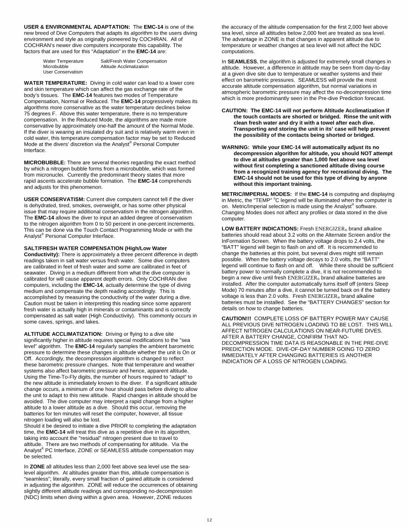
TABLE OF CONTENTS
Page Number
Product Introduction 1 Side Touch Contacts 1 Turning the Product On & Off 1 Main Operating Modes 1 Surface Interval 1 Dive Mode 2 Ascent Rate Bar Graph 3 Decompression Mode 3 Post Dive Interval Mode 4 Confined Water Protocol (Training mode) 4 Touch Contact Programming 4 Clock Programming 4
Clock Programming Procedure 4 Clock Programming Screens 5 Touch Programming Procedures 5 Programming Menus 5
Pre Dive Prediction 5 Information Display 6 Depth Alarm 6 Conservatism 6 Blend #1 O2 % 6 Logbook Mode 6
Logbook Screens 6 Warning Indications 7 Sensor Warning Mode 7
Sensor Warning Screen 7 Oxygen Toxicity Factors 7
Partial Pressure of Oxygen (PO2) 7 Central Nervous System Toxicity 8
Touch Programming Screens 8 Data Storage Types & Capacity 8 Inter-Dive Events 10 User Configurable Options 10 Product Specifications 11 Enhancements 11 Cleaning the Unit 11 Changing Batteries 11 Assistance, Repair, & Maintenance 11 Replacement Parts 11 Analyst® Personal Computer Interface 11 Product Certifications 12 Limited Warranty and Liability Statement 12 User & Environmental Adaptation 13 Low Battery Indications 13 Table of Contents 14 Figures Index 14
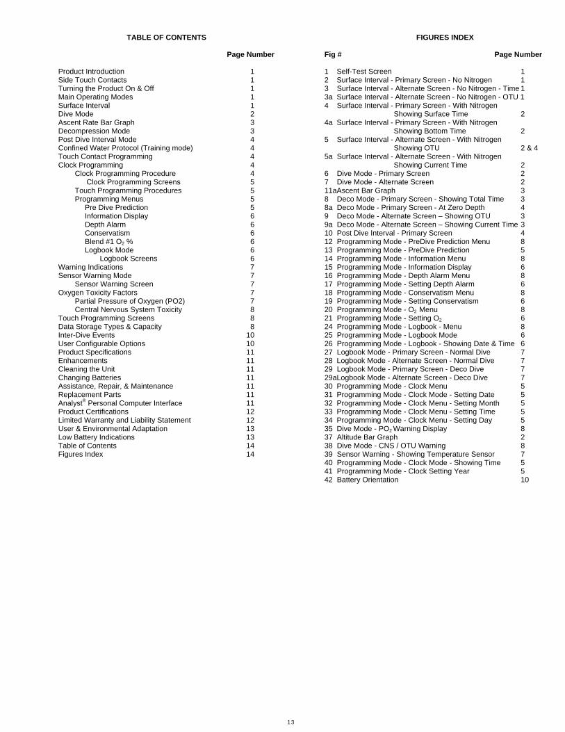
FIGURES INDEX
Fig # Page Number
1 Self-Test Screen 1 2 Surface Interval - Primary Screen - No Nitrogen 1 3 Surface Interval - Alternate Screen - No Nitrogen - Time 1 3a Surface Interval - Alternate Screen - No Nitrogen - OTU 1 4 Surface Interval - Primary Screen - With Nitrogen Showing Surface Time 2 4a Surface Interval - Primary Screen - With Nitrogen Showing Bottom Time 2 5 Surface Interval - Alternate Screen - With Nitrogen Showing OTU 2 & 4 5a Surface Interval - Alternate Screen - With Nitrogen Showing Current Time 2 6 Dive Mode - Primary Screen 2 7 Dive Mode - Alternate Screen 2 11aAscent Bar Graph 3 8 Deco Mode - Primary Screen - Showing Total Time 3 8a Deco Mode - Primary Screen - At Zero Depth 4 9 Deco Mode - Alternate Screen – Showing OTU 3 9a Deco Mode - Alternate Screen – Showing Current Time 3 10 Post Dive Interval - Primary Screen 4 12 Programming Mode - PreDive Prediction Menu 8 13 Programming Mode - PreDive Prediction 5 14 Programming Mode - Information Menu 8 15 Programming Mode - Information Display 6 16 Programming Mode - Depth Alarm Menu 8 17 Programming Mode - Setting Depth Alarm 6 18 Programming Mode - Conservatism Menu 8 19 Programming Mode - Setting Conservatism 6 20 Programming Mode - O2 Menu 8 21 Programming Mode - Setting O2 6 24 Programming Mode - Logbook - Menu 8 25 Programming Mode - Logbook Mode 6 26 Programming Mode - Logbook - Showing Date & Time 6 27 Logbook Mode - Primary Screen - Normal Dive 7 28 Logbook Mode - Alternate Screen - Normal Dive 7 29 Logbook Mode - Primary Screen - Deco Dive 7 29aLogbook Mode - Alternate Screen - Deco Dive 7 30 Programming Mode - Clock Menu 5 31 Programming Mode - Clock Mode - Setting Date 5 32 Programming Mode - Clock Menu - Setting Month 5 33 Programming Mode - Clock Menu - Setting Time 5 34 Programming Mode - Clock Menu - Setting Day 5 35 Dive Mode - PO2 Warning Display 8 37 Altitude Bar Graph 2 38 Dive Mode - CNS / OTU Warning 8 39 Sensor Warning - Showing Temperature Sensor 7 40 Programming Mode - Clock Mode - Showing Time 5 41 Programming Mode - Clock Setting Year 5 42 Battery Orientation 10

Cochran EMC-14
Owner's Manual
English - Imperial Ver: EMC-14i -1.00
1758 Firman Drive Richardson, Texas 75081, USA
Phone 972-644-6284 Fax 972-644-6286
www.divecochran.com