Embed Size (px)
Citation preview
VM801P Embedded Video Engine Plus Module Datasheet Version 1.0
Document Reference No.:FT_001102 Clearance No.: FTDI#426
Neither the whole nor any part of the information contained in, or the product described in this manual, may be adapted or
reproduced in any material or electronic form without the prior written consent of the copyright holder. This product and its
documentation are supplied on an as-is basis and no warranty as to their suitability for any particular purpose is either made or
implied. Future Technology Devices International Ltd will not accept any claim for damages howsoever arising as a result of use or failure of this product. Your statutory rights are not affected. This product or any variant of it is not intended for use in any medical
appliance, device or system in which the failure of the product might reasonably be expected to result in personal injury. This
document provides preliminary information that may be subject to change without notice. No freedom to use patents or other
intellectual property rights is implied by the publication of this document. Future Technology Devices International Ltd, Unit 1, 2
Seaward Place, Centurion Business Park, Glasgow G41 1HH United Kingdom. Scotland Registered Company Number: SC136640
FTDI Chip
VM801P Datasheet
Embedded Video
Engine
Plus Module
General Purpose Multi Media Controller
The VM801P is a development module for
FTDI’s FT801, which is used to develop and
demonstrate the functionality of the FT801
Embedded Video Engine, EVE. The VM801P is
a stand-alone display system which has a flash based microcontroller on board, thus providing a fully integrated display system ready to go.
The VM801P supports many I/O daughter cards or shields for expanding external interfacing and control. These shields use 1 or 2 Micro-MaTch miniature connectors to interface to the VM801P main module. Users will be able to purchase shields from FTDI Chip in the coming months, or alternatively can build their own shield for specific
applications.
The VM801P series of modules support 2 different LCD panel size options and are designed for industrial or commercial environments with precision fitted bezels in either black (-BK) or pearl (-PL).
VM801P43A-xx is the 4.3” LCD
VM801P50A-xx is the 5.0” LCD
The VM801P utilises the FTDI FT801 Embedded Video Engine, EVE. Graphic, audio and capacitive touch features of the FT801 chip can be accessed with the VM801P. For a full list of the FT801’s features please
see the FT801 datasheet.
The VM801P module has the following features:
FT801 for graphics, audio and touch processing
ATMEGA328P system microcontroller operating at 5V/16MHz supporting Arduino libraries
5 point Capacitive Touch screen LCD panel
Backlight LED driver
Audio power amplifier and micro speaker
FT232R USB serial port for firmware upgrade
Micro-SD socket for application storage, including 4GByte SD Card pre-loaded with sample applications
Battery backed Real Time Clock
2x Micro-MaTch miniature connectors for daughter card expansion
5V power supply from micro-USB or battery connector
Precision fitted bezel in black(-BK) or pearl (-PL)
VM801P Embedded Video Engine Plus Module Datasheet Version 1.0
Document Reference No.: FT_001102 Clearance No.: FTDI#426
Copyright © 2014 Future Technology Devices International Limited
1
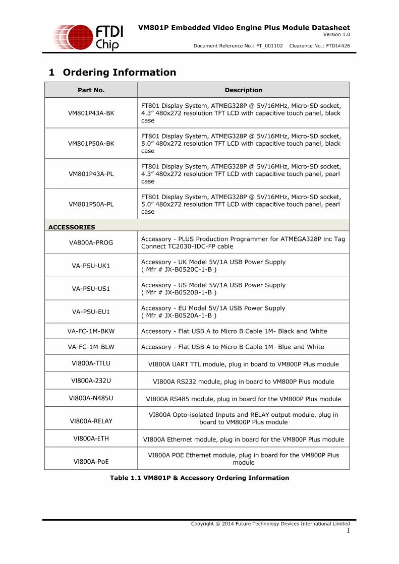
1 Ordering Information
Part No. Description
VM801P43A-BK FT801 Display System, ATMEG328P @ 5V/16MHz, Micro-SD socket, 4.3” 480x272 resolution TFT LCD with capacitive touch panel, black case
VM801P50A-BK FT801 Display System, ATMEG328P @ 5V/16MHz, Micro-SD socket, 5.0” 480x272 resolution TFT LCD with capacitive touch panel, black case
VM801P43A-PL
FT801 Display System, ATMEG328P @ 5V/16MHz, Micro-SD socket,
4.3” 480x272 resolution TFT LCD with capacitive touch panel, pearl case
VM801P50A-PL FT801 Display System, ATMEG328P @ 5V/16MHz, Micro-SD socket, 5.0” 480x272 resolution TFT LCD with capacitive touch panel, pearl case
ACCESSORIES
VA800A-PROG Accessory - PLUS Production Programmer for ATMEGA328P inc Tag Connect TC2030-IDC-FP cable
VA-PSU-UK1 Accessory - UK Model 5V/1A USB Power Supply
( Mfr # JX-B0520C-1-B )
VA-PSU-US1 Accessory - US Model 5V/1A USB Power Supply ( Mfr # JX-B0520B-1-B )
VA-PSU-EU1 Accessory - EU Model 5V/1A USB Power Supply
( Mfr # JX-B0520A-1-B )
VA-FC-1M-BKW Accessory - Flat USB A to Micro B Cable 1M- Black and White
VA-FC-1M-BLW Accessory - Flat USB A to Micro B Cable 1M- Blue and White
VI800A-TTLU VI800A UART TTL module, plug in board to VM800P Plus module
VI800A-232U VI800A RS232 module, plug in board to VM800P Plus module
VI800A-N485U VI800A RS485 module, plug in board for the VM800P Plus module
VI800A-RELAY VI800A Opto-isolated Inputs and RELAY output module, plug in
board to VM800P Plus module
VI800A-ETH VI800A Ethernet module, plug in board for the VM800P Plus module
VI800A-PoE VI800A POE Ethernet module, plug in board for the VM800P Plus
module
Table 1.1 VM801P & Accessory Ordering Information
VM801P Embedded Video Engine Plus Module Datasheet Version 1.0
Document Reference No.: FT_001102 Clearance No.: FTDI#426
Copyright © 2014 Future Technology Devices International Limited
2
Table of Contents
1 Ordering Information ...................................................................................................................... 1
2 Hardware Description ..................................................................................................................... 4
2.1 Physical Description ................................................................................................................ 5
2.1.1 Dimensions ...................................................................................................................... 5
2.2 Connectors and Jumpers......................................................................................................... 5
2.2.1 CN1 - 2-pin power connector .......................................................................................... 5
2.2.2 CN2 – Micro USB Receptacle .......................................................................................... 6
2.2.3 J2 – Audio Selection ........................................................................................................ 6
2.2.4 J5 – Expansion Connector for I/O Daughter Card ........................................................... 6
2.2.5 J6 - Expansion Connector for Comm Daughter Card ...................................................... 7
2.2.6 JP1 – Audio Amplifier Power Selection ........................................................................... 8
2.2.7 SW1 – 5V Power Source Selection .................................................................................. 8
2.2.8 JP4 – USB Power Selection .............................................................................................. 8
2.3 Board Schematics .................................................................................................................... 9
3 Hardware Setup Guide .................................................................................................................. 13
3.1 Power Configuration ............................................................................................................. 13
4 Arduino® Setup .............................................................................................................................. 14
4.1 Hardware Setup .................................................................................................................... 14
4.2 Software Setup ...................................................................................................................... 14
5 Assembling the Bezel and Panel Mounting .................................................................................. 17
5.1 Dimensions for 4.3” Bezel ..................................................................................................... 18
5.2 Dimensions for 5.0” Bezel ..................................................................................................... 19
6 Specifications ................................................................................................................................ 20
6.1 LCD Optical Specifications for 4.3” Panel .............................................................................. 20
6.2 LCD Optical Specifications for 5.0” Panel .............................................................................. 21
7 Contact Information ...................................................................................................................... 22
Appendix A – References ...................................................................................................................... 23
Document References ....................................................................................................................... 23
Acronyms and Abbreviations ............................................................................................................ 23
VM801P Embedded Video Engine Plus Module Datasheet Version 1.0
Document Reference No.: FT_001102 Clearance No.: FTDI#426
Copyright © 2014 Future Technology Devices International Limited
3
Appendix B – List of Tables & Figures ................................................................................................... 24
List of Tables ..................................................................................................................................... 24
List of Figures .................................................................................................................................... 24
Appendix C – Revision History .............................................................................................................. 25
VM801P Embedded Video Engine Plus Module Datasheet Version 1.0
Document Reference No.: FT_001102 Clearance No.: FTDI#426
Copyright © 2014 Future Technology Devices International Limited
4
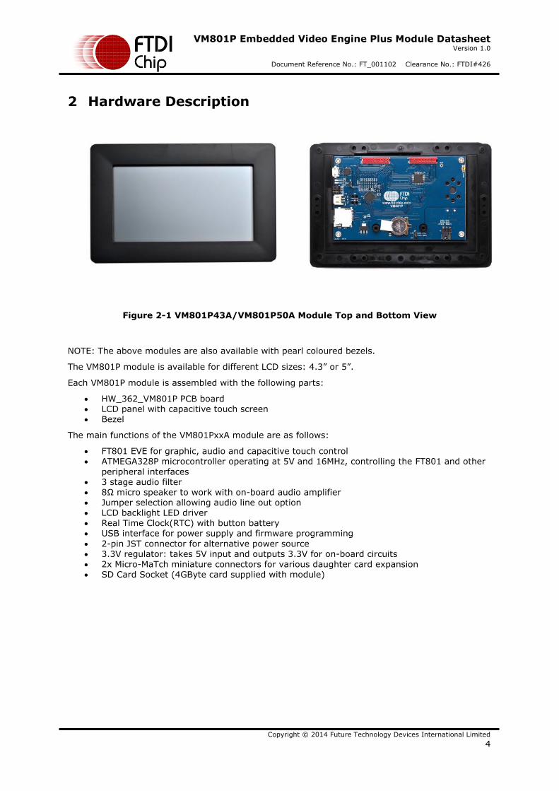
2 Hardware Description
Figure 2-1 VM801P43A/VM801P50A Module Top and Bottom View
NOTE: The above modules are also available with pearl coloured bezels.
The VM801P module is available for different LCD sizes: 4.3” or 5”.
Each VM801P module is assembled with the following parts:
HW_362_VM801P PCB board LCD panel with capacitive touch screen Bezel
The main functions of the VM801PxxA module are as follows:
FT801 EVE for graphic, audio and capacitive touch control ATMEGA328P microcontroller operating at 5V and 16MHz, controlling the FT801 and other
peripheral interfaces 3 stage audio filter 8Ω micro speaker to work with on-board audio amplifier Jumper selection allowing audio line out option LCD backlight LED driver Real Time Clock(RTC) with button battery USB interface for power supply and firmware programming
2-pin JST connector for alternative power source 3.3V regulator: takes 5V input and outputs 3.3V for on-board circuits 2x Micro-MaTch miniature connectors for various daughter card expansion SD Card Socket (4GByte card supplied with module)
VM801P Embedded Video Engine Plus Module Datasheet Version 1.0
Document Reference No.: FT_001102 Clearance No.: FTDI#426
Copyright © 2014 Future Technology Devices International Limited
5
46.2
23.2
102.8
61.2
106.7
68.6
64.8
3.8
5
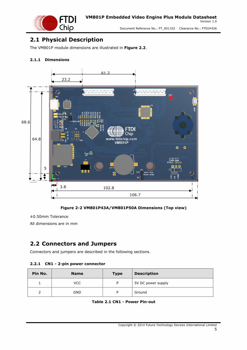
2.1 Physical Description
The VM801P module dimensions are illustrated in Figure 2.2.
2.1.1 Dimensions
Figure 2-2 VM801P43A/VM801P50A Dimensions (Top view)
±0.50mm Tolerance
All dimensions are in mm
2.2 Connectors and Jumpers
Connectors and jumpers are described in the following sections.
2.2.1 CN1 - 2-pin power connector
Pin No. Name Type Description
1 VCC P 5V DC power supply
2 GND P Ground
Table 2.1 CN1 - Power Pin-out
VM801P Embedded Video Engine Plus Module Datasheet Version 1.0
Document Reference No.: FT_001102 Clearance No.: FTDI#426
Copyright © 2014 Future Technology Devices International Limited
6
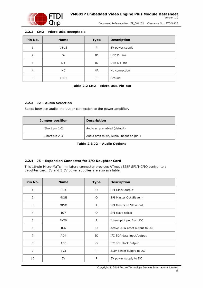
2.2.2 CN2 – Micro USB Receptacle
Pin No. Name Type Description
1 VBUS P 5V power supply
2 D- IO USB D- line
3 D+ IO USB D+ line
4 NC NA No connection
5 GND P Ground
Table 2.2 CN2 – Micro USB Pin-out
2.2.3 J2 – Audio Selection
Select between audio line-out or connection to the power amplifier.
Jumper position Description
Short pin 1-2 Audio amp enabled (default)
Short pin 2-3 Audio amp mute, Audio lineout on pin 1
Table 2.3 J2 – Audio Options
2.2.4 J5 – Expansion Connector for I/O Daughter Card
This 16-pin Micro-MaTch miniature connector provides ATmega328P SPI/I2C/IO control to a daughter card. 5V and 3.3V power supplies are also available.
Pin No. Name Type Description
1 SCK O SPI Clock output
2 MOSI O SPI Master Out Slave in
3 MISO I SPI Master In Slave out
4 IO7 O SPI slave select
5 INT0 I Interrupt input from DC
6 IO6 O Active LOW reset output to DC
7 AD4 IO I2C SDA data input/output
8 AD5 O I2C SCL clock output
9 3V3 P 3.3V power supply to DC
10 5V P 5V power supply to DC
VM801P Embedded Video Engine Plus Module Datasheet Version 1.0
Document Reference No.: FT_001102 Clearance No.: FTDI#426
Copyright © 2014 Future Technology Devices International Limited
7
Pin No. Name Type Description
11 GND P Ground
12 RST# O System reset output
13 IO5 IO GPIO
14 AD0 IO GPIO
15 AD7 AI ADC input
16 AD6 AI ADC input
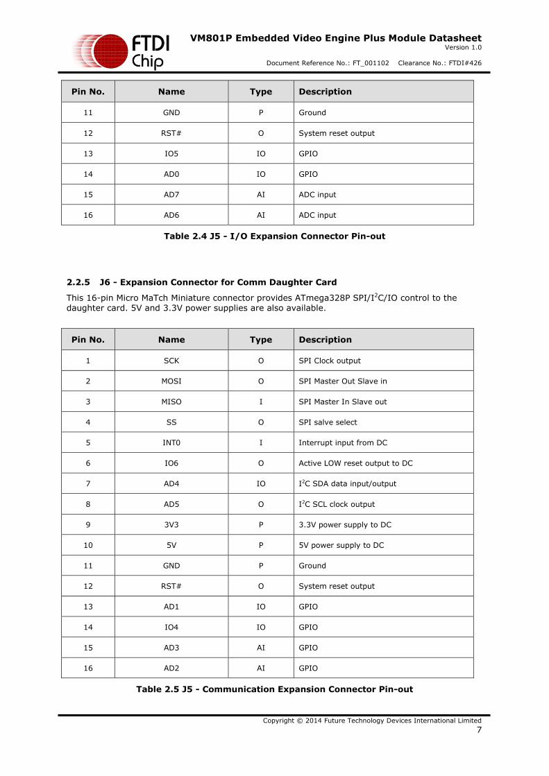
Table 2.4 J5 - I/O Expansion Connector Pin-out
2.2.5 J6 - Expansion Connector for Comm Daughter Card
This 16-pin Micro MaTch Miniature connector provides ATmega328P SPI/I2C/IO control to the daughter card. 5V and 3.3V power supplies are also available.
Pin No. Name Type Description
1 SCK O SPI Clock output
2 MOSI O SPI Master Out Slave in
3 MISO I SPI Master In Slave out
4 SS O SPI salve select
5 INT0 I Interrupt input from DC
6 IO6 O Active LOW reset output to DC
7 AD4 IO I2C SDA data input/output
8 AD5 O I2C SCL clock output
9 3V3 P 3.3V power supply to DC
10 5V P 5V power supply to DC
11 GND P Ground
12 RST# O System reset output
13 AD1 IO GPIO
14 IO4 IO GPIO
15 AD3 AI GPIO
16 AD2 AI GPIO
Table 2.5 J5 - Communication Expansion Connector Pin-out
VM801P Embedded Video Engine Plus Module Datasheet Version 1.0
Document Reference No.: FT_001102 Clearance No.: FTDI#426
Copyright © 2014 Future Technology Devices International Limited
8
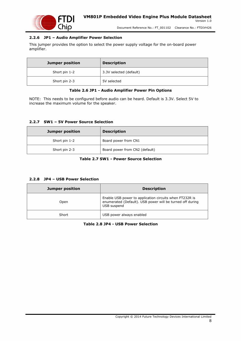
2.2.6 JP1 – Audio Amplifier Power Selection
This jumper provides the option to select the power supply voltage for the on-board power amplifier.
Jumper position Description
Short pin 1-2 3.3V selected (default)
Short pin 2-3 5V selected
Table 2.6 JP1 - Audio Amplifier Power Pin Options
NOTE: This needs to be configured before audio can be heard. Default is 3.3V. Select 5V to increase the maximum volume for the speaker.
2.2.7 SW1 – 5V Power Source Selection
Jumper position Description
Short pin 1-2 Board power from CN1
Short pin 2-3 Board power from CN2 (default)
Table 2.7 SW1 - Power Source Selection
2.2.8 JP4 – USB Power Selection
Jumper position Description
Open Enable USB power to application circuits when FT232R is enumerated (Default). USB power will be turned off during USB suspend
Short USB power always enabled
Table 2.8 JP4 - USB Power Selection
VM801P Embedded Video Engine Plus Module Datasheet Version 1.0
Document Reference No.: FT_001102 Clearance No.: FTDI#426
Copyright © 2014 Future Technology Devices International Limited
9
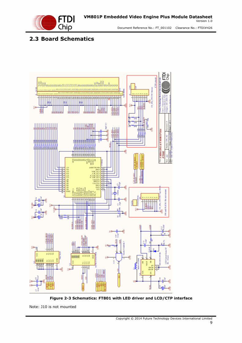
2.3 Board Schematics
Figure 2-3 Schematics: FT801 with LED driver and LCD/CTP interface
Note: J10 is not mounted
VM801P Embedded Video Engine Plus Module Datasheet Version 1.0
Document Reference No.: FT_001102 Clearance No.: FTDI#426
Copyright © 2014 Future Technology Devices International Limited
10
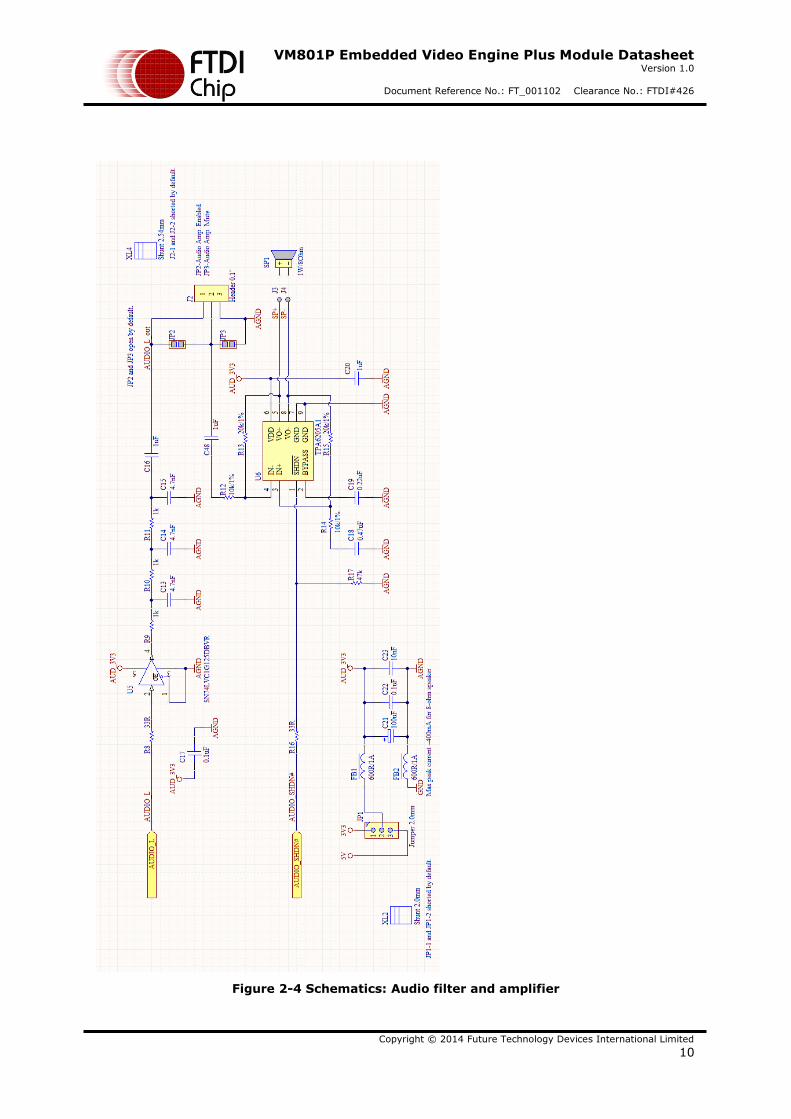
Figure 2-4 Schematics: Audio filter and amplifier
VM801P Embedded Video Engine Plus Module Datasheet Version 1.0
Document Reference No.: FT_001102 Clearance No.: FTDI#426
Copyright © 2014 Future Technology Devices International Limited
11
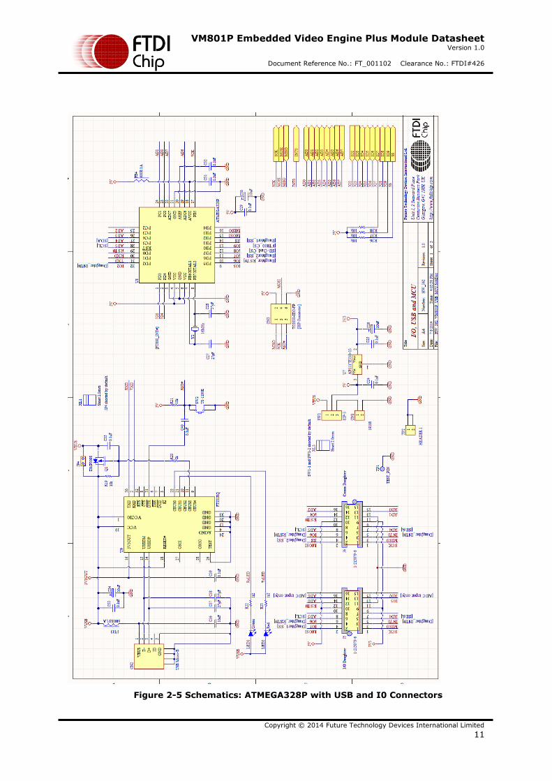
Figure 2-5 Schematics: ATMEGA328P with USB and I0 Connectors
VM801P Embedded Video Engine Plus Module Datasheet Version 1.0
Document Reference No.: FT_001102 Clearance No.: FTDI#426
Copyright © 2014 Future Technology Devices International Limited
12
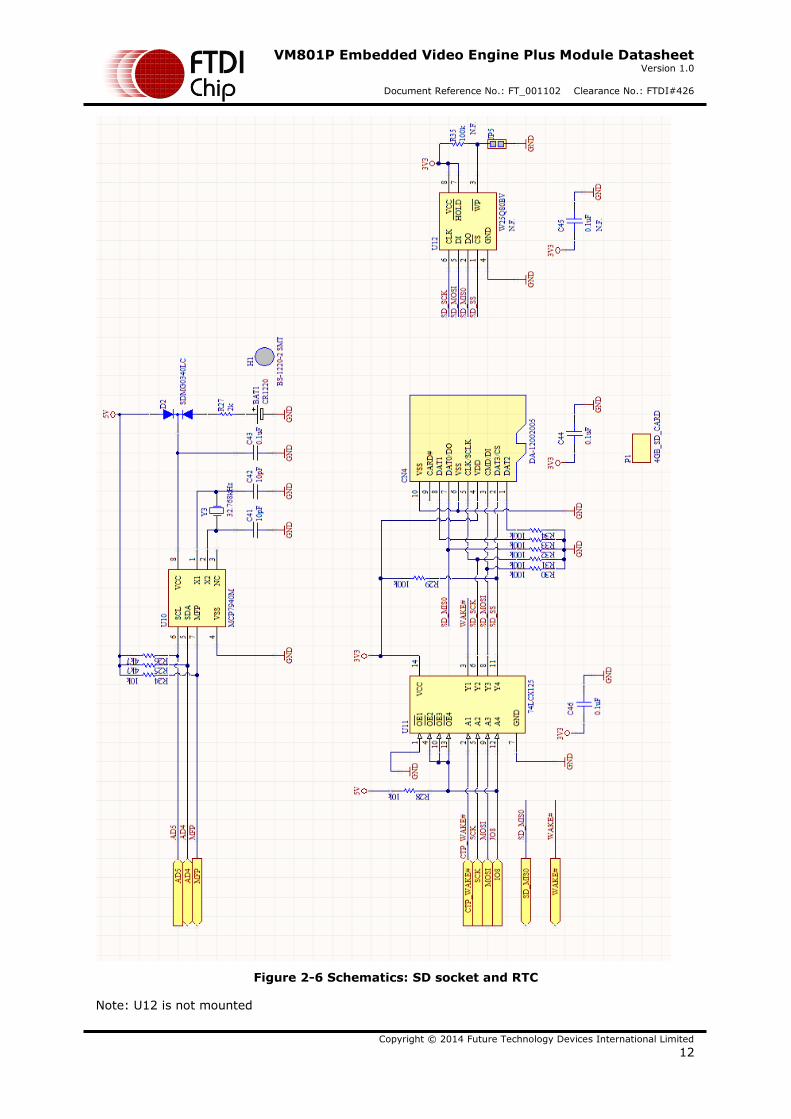
Figure 2-6 Schematics: SD socket and RTC
Note: U12 is not mounted
VM801P Embedded Video Engine Plus Module Datasheet Version 1.0
Document Reference No.: FT_001102 Clearance No.: FTDI#426
Copyright © 2014 Future Technology Devices International Limited
13
3 Hardware Setup Guide
3.1 Power Configuration
There are 2 methods of powering the VM801P board.
1) USB Power(5V) - Connect USB power through micro-USB cable to CN2
2) DC IN(5V) - Connect 5V to CN1
The following table summarizes how to power the VM801P board using the various methods.
Power Method CN1 CN2 SW1
USB Power N/C 5V Short pin 2-3 (default)
DC IN(5V) 5V 5V Short pin 1-2
Table 3.1 Board Power Configuration
VM801P Embedded Video Engine Plus Module Datasheet Version 1.0
Document Reference No.: FT_001102 Clearance No.: FTDI#426
Copyright © 2014 Future Technology Devices International Limited
14
4 Arduino® Setup
FTDI provides sample source code, sample application notes and a ready to run demo based on the Arduino® platform. Detailed information can be found at:
http://www.ftdichip.com/Support/Documents/AppNotes/AN_318_Arduino_Library_for_FT801_Series.pdf
http://www.ftdichip.com/Support/Documents/AppNotes/AN_275_FT801_Example_with_Arduino.pdf
http://www.ftdichip.com/Support/Documents/AppNotes/AN_246%20VM801CB_SampleApp_Arduino_Introduction.pdf
4.1 Hardware Setup
Connect a USB cable (suggest FTDI accessory VA-FC-1M-BKW or VA-FC-1M-BLW) from the VM801P USB port CN2 to the PC USB host port or self-powered hub port.
The USB will supply power to the VM801P module after the FTDI FT232R driver is properly loaded and the USB host completes USB device configuration.
4.2 Software Setup
The arduino code can be downloaded from the Arduino IDE to the ATMEGA328P through the USB connector CN2 connected to the PC. The USB connector CN2 is also used to display debug output
from the ATMEGA328P to the PC terminal application.
Default sample code is downloaded to the ATMEGA328P during the VM801P module manufacturing. When the VM801P is connected to the PC through the USB connector CN2, the
VM801P is powered up and the sample code is functional with the demo applications.
Download the Arduino IDE from http://arduino.cc/en/main/software. Install the Arduino IDE
Open the Arduino IDE Open the FT801 sample project to be downloaded to the VM801P
(Examples are available from: http://www.ftdichip.com/Support/SoftwareExamples/FT800_Projects.htm
Or you may have developed your own code)
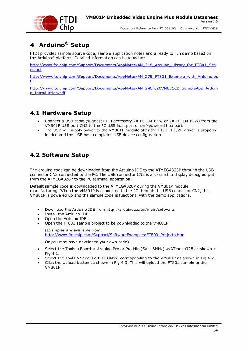
Select the Tools->Board-> Arduino Pro or Pro Mini(5V, 16MHz) w/ATmega328 as shown in Fig 4.1.
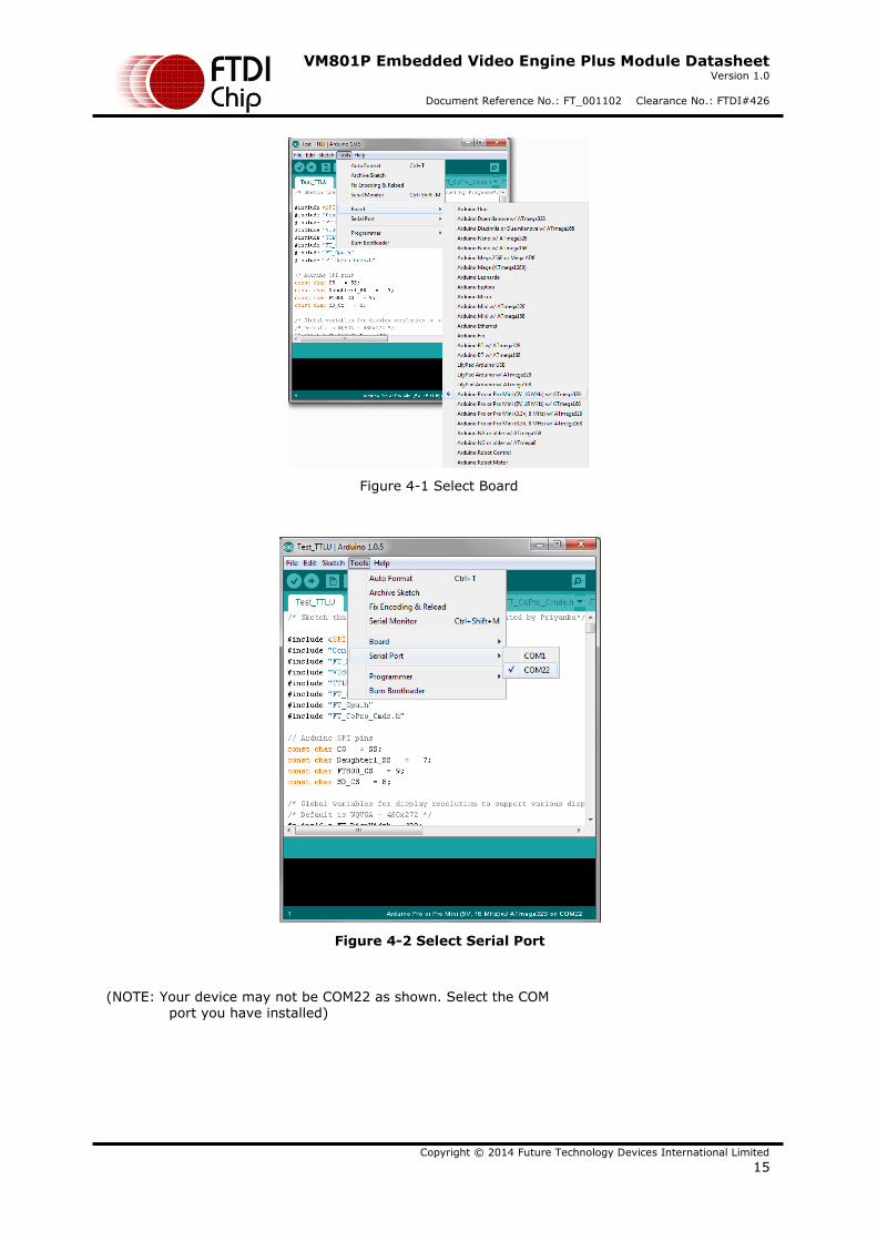
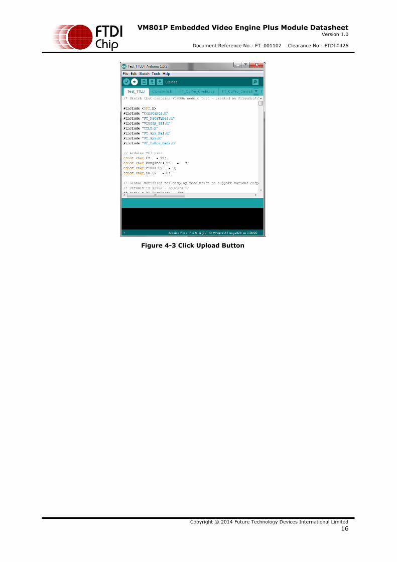
Select the Tools->Serial Port->COMxx corresponding to the VM801P as shown in Fig 4.2. Click the Upload button as shown in Fig 4.3. This will upload the FT801 sample to the
VM801P.
VM801P Embedded Video Engine Plus Module Datasheet Version 1.0
Document Reference No.: FT_001102 Clearance No.: FTDI#426
Copyright © 2014 Future Technology Devices International Limited
15
Figure 4-1 Select Board
Figure 4-2 Select Serial Port
(NOTE: Your device may not be COM22 as shown. Select the COM port you have installed)
VM801P Embedded Video Engine Plus Module Datasheet Version 1.0
Document Reference No.: FT_001102 Clearance No.: FTDI#426
Copyright © 2014 Future Technology Devices International Limited
16
Figure 4-3 Click Upload Button
VM801P Embedded Video Engine Plus Module Datasheet Version 1.0
Document Reference No.: FT_001102 Clearance No.: FTDI#426
Copyright © 2014 Future Technology Devices International Limited
17
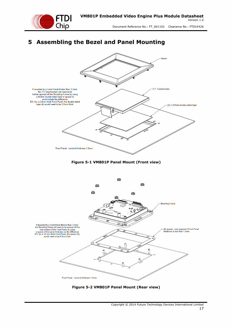
5 Assembling the Bezel and Panel Mounting
Figure 5-1 VM801P Panel Mount (Front view)
Figure 5-2 VM801P Panel Mount (Rear view)
VM801P Embedded Video Engine Plus Module Datasheet Version 1.0
Document Reference No.: FT_001102 Clearance No.: FTDI#426
Copyright © 2014 Future Technology Devices International Limited
18
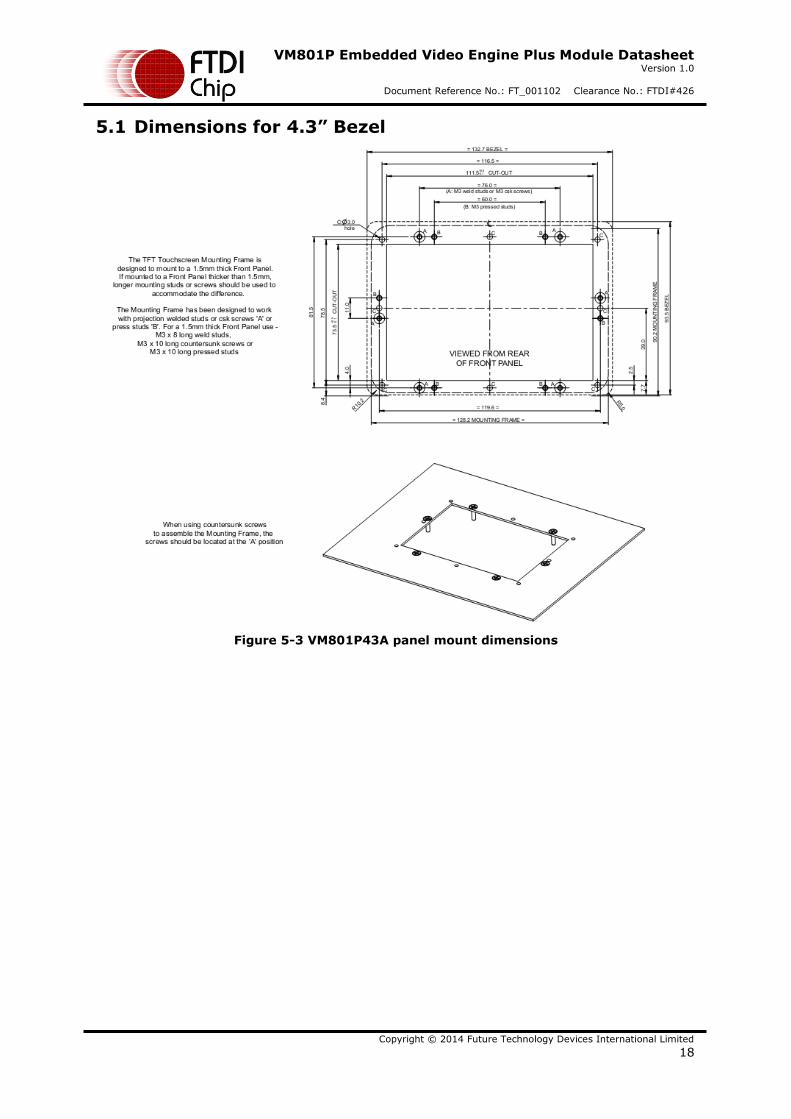
5.1 Dimensions for 4.3” Bezel
Figure 5-3 VM801P43A panel mount dimensions
VM801P Embedded Video Engine Plus Module Datasheet Version 1.0
Document Reference No.: FT_001102 Clearance No.: FTDI#426
Copyright © 2014 Future Technology Devices International Limited
19
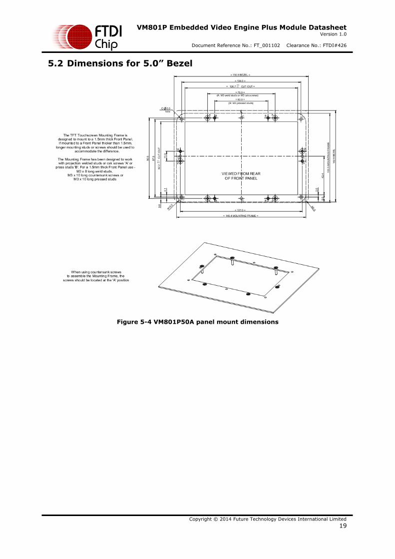
5.2 Dimensions for 5.0” Bezel
Figure 5-4 VM801P50A panel mount dimensions
VM801P Embedded Video Engine Plus Module Datasheet Version 1.0
Document Reference No.: FT_001102 Clearance No.: FTDI#426
Copyright © 2014 Future Technology Devices International Limited
20
6 Specifications
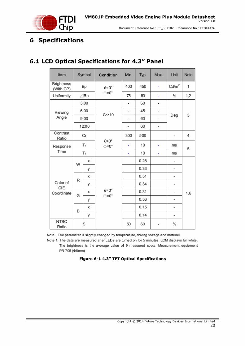
6.1 LCD Optical Specifications for 4.3” Panel
Figure 6-1 4.3” TFT Optical Specifications
VM801P Embedded Video Engine Plus Module Datasheet Version 1.0
Document Reference No.: FT_001102 Clearance No.: FTDI#426
Copyright © 2014 Future Technology Devices International Limited
21
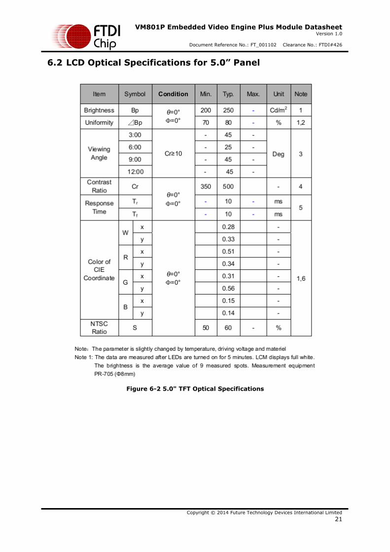
6.2 LCD Optical Specifications for 5.0” Panel
Figure 6-2 5.0" TFT Optical Specifications
VM801P Embedded Video Engine Plus Module Datasheet Version 1.0
Document Reference No.: FT_001102 Clearance No.: FTDI#426
Copyright © 2014 Future Technology Devices International Limited
22
7 Contact Information
Head Office – Glasgow, UK Future Technology Devices International Limited Unit 1, 2 Seaward Place, Centurion Business Park Glasgow G41 1HH United Kingdom Tel: +44 (0) 141 429 2777 Fax: +44 (0) 141 429 2758 E-mail (Sales) [email protected] E-mail (Support) [email protected] E-mail (General Enquiries) [email protected]
Branch Office – Taipei, Taiwan Future Technology Devices International Limited (Taiwan) 2F, No. 516, Sec. 1, NeiHu Road Taipei 114 Taiwan , R.O.C. Tel: +886 (0) 2 8791 3570 Fax: +886 (0) 2 8791 3576 E-mail (Sales) [email protected] E-mail (Support) [email protected] E-mail (General Enquiries) [email protected]
Branch Office – Tigard, Oregon, USA Future Technology Devices International Limited (USA) 7130 SW Fir Loop Tigard, OR 97223-8160 USA Tel: +1 (503) 547 0988 Fax: +1 (503) 547 0987 E-Mail (Sales) [email protected] E-Mail (Support) [email protected] E-Mail (General Enquiries) [email protected]
Branch Office – Shanghai, China Future Technology Devices International Limited (China) Room 1103, No. 666 West Huaihai Road, Shanghai, 200052 China Tel: +86 21 62351596 Fax: +86 21 62351595 E-mail (Sales) [email protected] E-mail (Support) [email protected] E-mail (General Enquiries) [email protected]
Web Site http://ftdichip.com
System and equipment manufacturers and designers are responsible to ensure that their systems, and any Future Technology
Devices International Ltd (FTDI) devices incorporated in their systems, meet all applicable safety, regulatory and system-level performance requirements. All application-related information in this document (including application descriptions, suggested
FTDI devices and other materials) is provided for reference only. While FTDI has taken care to assure it is accurate, this
information is subject to customer confirmation, and FTDI disclaims all liability for system designs and for any applications
assistance provided by FTDI. Use of FTDI devices in life support and/or safety applications is entirely at the user’s risk, and the
user agrees to defend, indemnify and hold harmless FTDI from any and all damages, claims, suits or expense resulting from
such use. This document is subject to change without notice. No freedom to use patents or other intellectual property rights is
implied by the publication of this document. Neither the whole nor any part of the information contained in, or the product
described in this document, may be adapted or reproduced in any material or electronic form without the prior written consent
of the copyright holder. Future Technology Devices International Ltd, Unit 1, 2 Seaward Place, Centurion Business Park, Glasgow G41 1HH, United Kingdom. Scotland Registered Company Number: SC136640
VM801P Embedded Video Engine Plus Module Datasheet Version 1.0
Document Reference No.: FT_001102 Clearance No.: FTDI#426
Copyright © 2014 Future Technology Devices International Limited
23
Appendix A – References
Document References
For module documentations, please refer to URL below:
http://www.ftdichip.com/Products/modules/VM801P.html
FT801 datasheet: DS_FT801
FT801 software programming guide: FT800_Series_Programmers_Guide
AN_318: Arduino Library for FT800 Series
AN_275 : FT800 Example with Arduino
AN_246: VM800CB SampleApp_Arduino Introduction
AN_299: FT800 FT801 Internal Clock Trimming
AN_333: FT800 and FT801 Touch Capabilities
Acronyms and Abbreviations
Terms Description
CTP Capacitive Touch Panel
IO Input Output
I2C Inter Integrated Circuit
LCD Liquid Crystal Display
LED Light-Emitting Diode
RTC Real Time Clock
SD Card Secure Digital Card
SPI Serial Peripheral Interface
USB Universal Serial Bus
VM801P Embedded Video Engine Plus Module Datasheet Version 1.0
Document Reference No.: FT_001102 Clearance No.: FTDI#426
Copyright © 2014 Future Technology Devices International Limited
24
Appendix B – List of Tables & Figures
List of Tables
Table 1.1 VM801P & Accessory Ordering Information ............................................................... 1
Table 2.1 CN1 - Power Pin-out .............................................................................................. 5
Table 2.2 CN2 – Micro USB Pin-out ........................................................................................ 6
Table 2.3 J2 – Audio Options ................................................................................................ 6
Table 2.4 J5 - I/O Expansion Connector Pin-out ...................................................................... 7
Table 2.5 J5 - Communication Expansion Connector Pin-out ..................................................... 7
Table 2.6 JP1 - Audio Amplifier Power Pin Options ................................................................... 8
Table 2.7 SW1 - Power Source Selection ................................................................................ 8
Table 2.8 JP4 - USB Power Selection ..................................................................................... 8
Table 3.1 Board Power Configuration ................................................................................... 13
List of Figures
Figure 2-1 VM801P43A/VM801P50A Module Top and Bottom View ............................................ 4
Figure 2-2 VM801P43A/VM801P50A Dimensions (Top view) ..................................................... 5
Figure 2-3 Schematics: FT801 with LED driver and LCD/CTP interface ....................................... 9
Figure 2-4 Schematics: Audio filter and amplifier .................................................................. 10
Figure 2-5 Schematics: ATMEGA328P with USB and I0 Connectors .......................................... 11
Figure 2-6 Schematics: SD socket and RTC .......................................................................... 12
Figure 4-1 Select Board ..................................................................................................... 15
Figure 4-2 Select Serial Port ............................................................................................... 15
Figure 4-3 Click Upload Button ........................................................................................... 16
Figure 5-1 VM801P Panel Mount (Front view) ....................................................................... 17
Figure 5-2 VM801P Panel Mount (Rear view) ........................................................................ 17
Figure 5-3 VM801P43A panel mount dimensions ................................................................... 18
Figure 5-4 VM801P50A panel mount dimensions ................................................................... 19
Figure 6-1 4.3” TFT Optical Specifications ............................................................................ 20
Figure 6-2 5.0" TFT Optical Specifications ............................................................................ 21
VM801P Embedded Video Engine Plus Module Datasheet Version 1.0
Document Reference No.: FT_001102 Clearance No.: FTDI#426
Copyright © 2014 Future Technology Devices International Limited
25
Appendix C – Revision History
Document Title: VM801P Embedded Video Engine Plus Module Datasheet
Document Reference No.: FT_001102
Clearance No.: FTDI#426
Product Page: www.ftdichip.com/Products/Modules/VM801P.html
Document Feedback: Send Feedback
Revision Changes Date
1.0 First release 2014-11-25