Embed Size (px)
Citation preview
10/10/2013
1
1
Embedded Systems technologies
Riferimenti bibliografici
“Embedded System Design: A Unified Hardware/Software Introduction” , Frank Vahid, Tony Givargis,
John Wiley & Sons Inc., ISBN:0-471-38678-2, 2002.
“Computers as Components: Principles of Embedded Computer Systems Design ”, Wayne Wolf, Morgan
Kaufmann Publishers, ISBN: 1-55860-541-X, 2001
Embedded System Design” by Peter Marwedel, Kluwer Academic Publishers, ISBN: 1-4020-7690-8,
October 2003
2
Three key embedded system technologies
Technology
A manner of accomplishing a task, especially using
technical processes, methods, or knowledge
Three key technologies for embedded systems
Processor technology
IC technology
Design technology

10/10/2013
2
3
Processor technology
Application-specific
Registers
Custom
ALU
Datapath Controller
Program memory
Assembly code
for:
total = 0
for i =1 to …
Control logic
and State
register
Data
memory
IR PC
Single-purpose (“hardware”)
Datapath Controller
Control
logic
State
register
Data
memory
index
total
+
IR PC
Register
file
General
ALU
Datapath Controller
Program
memory
Assembly code
for:
total = 0
for i =1 to …
Control
logic and
State register
Data
memory
General-purpose (“software”)
The architecture of the computation engine used to implement a system’s desired functionality
Processor does not have to be programmable
“Processor” not equal to general-purpose processor
4
Processor technology
total = 0;
for (i = 0; i< N; i++)
total += M[i];
General-purpose
processor
Single-purpose
processor
Application-specific
processor
Desired
functionality
Processors vary in their customization for the problem at hand
10/10/2013
3
5
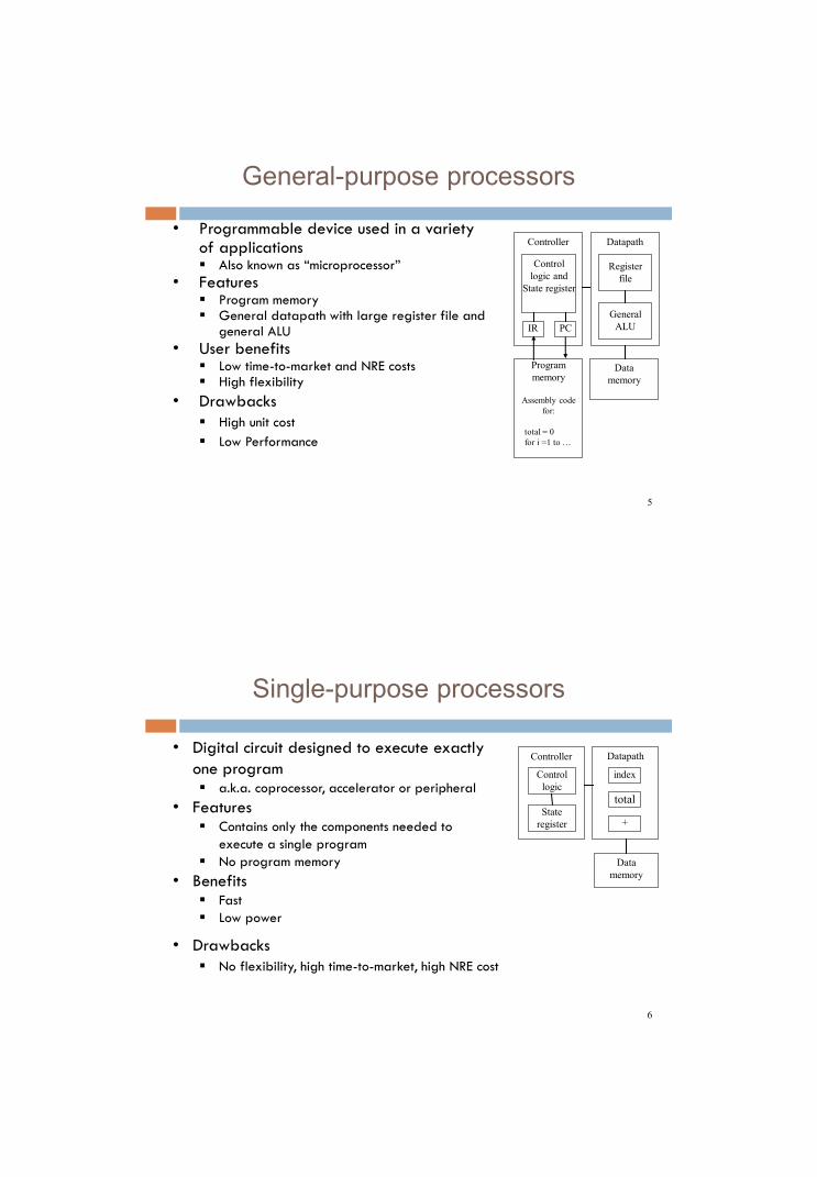
General-purpose processors
• Programmable device used in a variety of applications Also known as “microprocessor”
• Features Program memory General datapath with large register file and
general ALU
• User benefits Low time-to-market and NRE costs High flexibility
• Drawbacks
High unit cost
Low Performance
IR PC
Register
file
General
ALU
Datapath Controller
Program
memory
Assembly code
for:
total = 0
for i =1 to …
Control
logic and
State register
Data
memory
6
Single-purpose processors
• Digital circuit designed to execute exactly
one program a.k.a. coprocessor, accelerator or peripheral
• Features Contains only the components needed to
execute a single program
No program memory
• Benefits Fast
Low power Small size
• Drawbacks
No flexibility, high time-to-market, high NRE cost
Datapath Controller
Control
logic
State
register
Data
memory
index
total
+

10/10/2013
4
7
Single-purpose processors
+
Index
4
+
Total
Memory
Rst_Index
Rst_Total
Clk_Index
Clk_Total
N Compare Cond
Control
Unit
Datapath
8
Application-specific processors
• Programmable processor optimized for a
particular class of applications having common
characteristics Compromise between general-purpose and single-
purpose processors
• Features Program memory
Optimized datapath
Special functional units
• Benefits Some flexibility, good performance, size and power
• Drawbacks
High NRE cost (processor and compiler)
• Examples: Microcontroller, DSP
IR PC
Registers
Custom
ALU
Datapath Controller
Program
memory
Assembly code
for:
total = 0;
for(i =0;i<N;i++)
total+=M[i];
Control
logic and
State register
Data
memory

10/10/2013
5
9
A Common ASIP: Microcontroller
• For embedded control applications – Reading sensors, setting actuators
– Mostly dealing with events (bits): data is present, but not in huge amounts
– e.g., VCR, disk drive, digital camera (assuming SPP for image compression), washing machine, microwave oven
•Microcontroller features – On-chip peripherals
• Timers, analog-digital converters, serial communication, etc.
• Tightly integrated for programmer, typically part of register space
– On-chip program and data memory
– Directprogrammeraccesstomanyofthechip’spins
– Specialized instructions for bit-manipulation and other low-level
10
Digital Signal Processors (DSP)
• For signal processing applications
– Large amounts of digitized data, often streaming
– Data transformations must be applied fast
– e.g., cell-phone voice filter, digital TV, music synthesizer
• DSP features
– Several instruction execution units
– Multiple-accumulate single-cycle instruction, other instrs.
– Efficient vector operations – e.g., add two arrays
• Vector ALUs, loop buffers, etc.

10/10/2013
6
Integrated Circuit Technology
12
Integrated circuit (IC) technology
source drain channel
oxide
gate
Silicon substrate
IC package IC
The manner in which a digital (gate-level)
implementation is mapped onto an IC
IC: Integrated circuit, or “chip”
IC technologies differ in their customization to a design
IC’s consist of numerous layers (perhaps 10 or more)
IC technologies differ with respect to who builds each layer
and when

10/10/2013
7
The basic electrical component in digital systems
Acts as an on/off switch
Voltage at “gate” controls whether current flows
from source to drain
Don’t confuse this “gate” with a logic gate
CMOS transistor
gate
source
drain
Conducts if gate=1
CMOS transistor
Source, Drain
Diffusion area where electrons can flow
Can be connected to metal contacts (via’s)
Gate
Polysilicon area where control voltage is applied
Oxide
Si O2 Insulator so the gate voltage can’t leak

10/10/2013
8
Complementary Metal
Oxide Semiconductor
• We refer to logic levels
– Typically 0 is 0V, 1 is Vdd
• Two basic CMOS types
– nMOS conducts if gate=1
– pMOS conducts if gate=0
– Hence “complementary”
• Basic gates
– Inverter, NAND, NOR
CMOS transistor implementations
x F = x'
1
inverter
0
F = (xy)'
x
1
x
y
y
NAND gate
0
1
F = (x+y)'
x y
x
y
NOR gate
0
gate
source
drain
nMOS
Conducts if gate=1
gate
source
drain
pMOS
Conducts if gate=0
16
IC technology
NAND

10/10/2013
9
IC Technologies
Three types of IC technologies
Full-custom/VLSI
Semi-custom ASIC (gate array and standard cell)
PLD (Programmable Logic Device)
Full-custom
Very Large Scale Integration (VLSI)
All layers are optimized for an embedded system’s particular digital implementation
Placement
Place and orient transistors
Routing
Connect transistors
Sizing
Make fat, fast wires or thin, slow wires
May also need to size buffer
Benefits
Excellent performance, small size, low power

10/10/2013
10
19
Full-custom/VLSI
Drawbacks
High NRE cost (e.g., $300k), long time-to-market
Hand design
Horrible time-to-market/flexibility/NRE cost…
Reserve for the most important units in a processor
ALU, Instruction fetch…
Physical design tools
Less optimal, but faster…
20
Semi-custom
Lower layers are fully or partially built
Designers are left with routing of wires and maybe
placing some blocks
Benefits
Good performance, good size, less NRE cost than a full-
custom implementation (perhaps $10k to $100k)
Drawbacks
Still require weeks to months to develop

10/10/2013
11
Semi-custom
Gate Array
Array of prefabricated gates
“place” and route
Higher density, faster time-to-market
Does not integrate as well with full-custom
Standard Cell
A library of pre-designed cell
Place and route
Lower density, higher complexity
Integrate great with full-custom
Gate array
Standard Cell
22
PLD (Programmable Logic Device)
Programmable Logic Device
Programmable Logic Array, Programmable Array Logic, Field Programmable Gate Array
All layers already exist
Designers can purchase an IC
To implement desired functionality
Connections on the IC are either created or destroyed to implement
Benefits
Very low NRE costs
Great time to market
Drawback
High unit cost, bad for large volume
Power
Except special PLA
slower

10/10/2013
12
23
Programmable Logic Array (PLA)
24
FPGA

10/10/2013
13
Configurable Logic Block (CLB)
I/O block

10/10/2013
14
27
General-
purpose
processor
ASIP Single-
purpose
processor
Semi-custom PLD Full-custom
General,
providing improved:
Customized,
providing improved:
Power efficiency
Performance
Size
Cost (high volume)
Flexibility
Maintainability
NRE cost
Time- to-prototype
Time-to-market
Cost (low volume)
Independence of processor and IC
technologies
Design Technology
10/10/2013
15
Design Technology
• A procedure for designing a system
• Many systems are complex and pose many design
challenges: Large specifications, short time-to-market, high
performance, multiple designers, interface to manufacturing.
• Proper design methodology helps to manage the design
process and improves quality, performance and design costs
Design flow
• A sequence of design steps in a design methodology
• The design flow can be partially or fully automated
• A set or tools can be used to automate the methodology
steps:
– Software engineering tools,
– Compilers,
– Computer-Aided Design tools,
– etc

10/10/2013
16
31
Design Technology
Libraries/IP: Incorporates pre-
designed implementation from
lower abstraction level into
higher level.
System
specification
Behavioral
specification
RT
specification
Logic
specification
To final implementation
Compilation/Synthesis:
Automates exploration and
insertion of implementation
details for lower level.
Test/Verification: Ensures
correct functionality at each
level, thus reducing costly
iterations between levels.
Compilation/
Synthesis
Libraries/
IP
Test/
Verification
System
synthesis
Behavior
synthesis
RT
synthesis
Logic
synthesis
Hw/Sw/
OS
Cores
RT
components
Gates/
Cells
Model simulat./
checkers
Hw-Sw
cosimulators
HDL simulators
Gate
simulators
HLL model
Behavioral model
RT model
Logic model
IC Design Steps
Specifications Specifications High-level
Description
High-level
Description
Functional
Description
Functional
Description
Behavioral
VHDL, C
Structural
VHDL

10/10/2013
17
IC Design Steps
Packaging
Fabri- cation
Physical
Design
Technology
Mapping
Synthesis
Specifications Specifications High-level
Description
High-level
Description
Functional
Description
Functional
Description
Placed
& Routed
Design
Placed
& Routed
Design
X=(AB*CD)+
(A+D)+(A(B+C))
Y = (A(B+C)+AC+
D+A(BC+D))
Gate-level
Design
Gate-level
Design Logic
Description
Logic
Description
Circuit Models
A model of a circuit is an abstraction
A representation that shows relevant features without associated details
Circuit Model
(few details)
Circuit Model
(few details)
Circuit Model
(many details)
Circuit Model
(many details) Synthesis Synthesis

10/10/2013
18
Model Classification
Views of a Model
Behavioral
Describe the function of a circuit regardless of its implementation
Structural
Describe a model as an interconnection of components
Physical
Relate to the physical object (e.g., transistors) of a design

10/10/2013
19
The Y-chart
Architectural-level
Logic-level
Geometrical-level
Behavioral-view Structural-view
Physical-view
GajskiandKuhn’sY-chart
(Silicon Compilers, Addison-Wesley, 1987)
The Y-chart
Behavioral-view Structural-view
Physical-view
Architectural
level
Logic level
Geometrical
level
…
PC = PC + 1;
Fetch(PC);
Decode(Inst);
...
MULT
ADD
RAM
CTRL
S0
S2
S3 S1

10/10/2013
20
Synthesis
Architectural-level
Logic-level
Geometrical-level
Behavioral-view Structural-view
Physical-view
High-level synthesis
(or architectural synthesis)
Logic synthesis
Physical design
Assignment to resources
Interconnection
Scheduling
Interconnection of istances
of library cells (technology
mapping)
Physical layout of the chip
(placement, routing)
40
Moore’sLaw
Gordon Moore predicted in 1965 that the number of transistors that can be integrated on a die would double every 18 months.

10/10/2013
21
Device Complexity
Exponential increase in device
complexity
Increasing with Moore's law (or faster)!
Require exponential increases in design
productivity
We have exponentially more transistors! We have exponentially more transistors!
Heterogeneity on Chip
Greater diversity of on chip elements
Processors
Software
Memory
Analog
More transistors doing different things! More transistors doing different things!

10/10/2013
22
Stronger Market Pressures
Time–to-market
Decreasing design window
Less tolerance for design revisions
44
Design productivity gap
Role of EDA: close the productivity gap
Lo
gic
tra
nsis
tors
pe
r ch
ip
(K
)

10/10/2013
23
45
Design productivity gap
10,000
1,000
100
10
1
0.1
0.01
0.001
Logic
tran
sist
ors
per
chip
(in
mil
lio
ns)
100,000
10,000
1000
100
10
1
0.1
0.01
Pro
duct
ivi
ty
(K)
Tra
ns.
/Sta
ff-M
o.
IC capacity
productivity
Gap
While designer productivity has grown at an impressive rate
over the past decades, the rate of improvement has not kept
pace with chip capacity
46
Design productivity gap
10,000
1,000
100
10
1
0.1
0.01
0.001
Logic
tran
sist
ors
per
chip
(in
mil
lio
ns
)
100,000
10,000
1000
100
10
1
0.1
0.01
Pro
duct
ivit
y
(K)
Tra
ns.
/
Sta
ff-
Mo. IC capacity
productivity
Gap
1981 leading edge chip required 100 designer months
10,000 transistors / 100 transistors/month
2002 leading edge chip requires 30,000 designer months
150,000,000 / 5000 transistors/month
Designer cost increase from $1M to $300M

10/10/2013
24
The situation is even worse than the productivity gap indicates
In theory, adding designers to team reduces project completion time
In reality, productivity per designer decreases due to complexities of team management
and communication
In the software community, known as “the mythical man-month” (Brooks 1975)
At some point, can actually lengthen project completion time! (“Too many cooks”)
• 1M transistors, 1
designer=5000 trans/month
• Each additional designer
reduces for 100 trans/month
• So 2 designers produce 4900
trans/month each
10 20 30 40 0
10000
20000
30000
40000
50000
60000
43
24
19
16 15
16 18
23
Team
Individual
Months until completion
Number of designers
The mythical man-month
48
Managing the design productivity crisis
• IP (Intellectual Property) Reuse
Assembly of predesigned Intellectual
Property components, often from external vendors
Soft and Hard IPs
• System-Level Design and verification
Rather than at the RTL or gate-level
Focus on Interface and Communication

10/10/2013
25
Evolution of Design Methodology
We are now entering the era of block-based design
ASIC/ASSP
Design
System-Board
Integration
Yesterday
Bus Standards,
Predictable, Preverified
Today
VSI Compatible Standards,
Predictable, Preverified
IP/Block
Authoring
System-Chip
Integration
Evolution of SoC Platforms
General-purpose
Scalable RISC
Processor
to 300+ MHz 50•
bit or 64-bit-32•
Library of Device
IP Blocks
Image•
coprocessors
DSPs•
UART•
1394•
USB•
Scalable VLIW
Media Processor:
to 300+ MHz 100•
bit or 64-bit-32•
Nexperia™
System Buses
bit 32-128•
2 Cores: Philips’NexperiaPNX8850 SoC platform for High-end digital video (2001)

10/10/2013
26
What’s Happening in SoCs?
Technology: no slow-down in sight!
Faster and smaller transistors: 90 65 45 32 22 nm
…butslowerwires,lowervoltage,morenoise! 80% or more of the delay of critical paths will be due to interconnects
Design complexity: from 2 to 10 to 100 cores! Design reuse is essential
…butdifferentiation/innovationiskeyforwinningonthemarket!
Performance and power: Performance requirements keep going up
…butpowerbudgetsdon’t!
Communication Architectures
Shared bus
Low area
Poor scalability
High energy consumption
Network-on-Chip
Scalability and modularity
Low energy consumption
Increase of design complexity
Shared bus
IP IP IP
IP IP IP
IP IP IP IP
IP IP IP IP
IP IP IP IP
IP IP IP IP

10/10/2013
27
Intel’s Teraflops
100 Million transistors
80 cores, 160 FP engines
Teraflops perf. @ 62 Watts
On-die mesh network
Power aware design