Embed Size (px)
Citation preview

UM005 1
Firmware v0.5.0.0
Document Revision 2.22
VN-300 User Manual Embedded Navigation Solutions
2 UM005
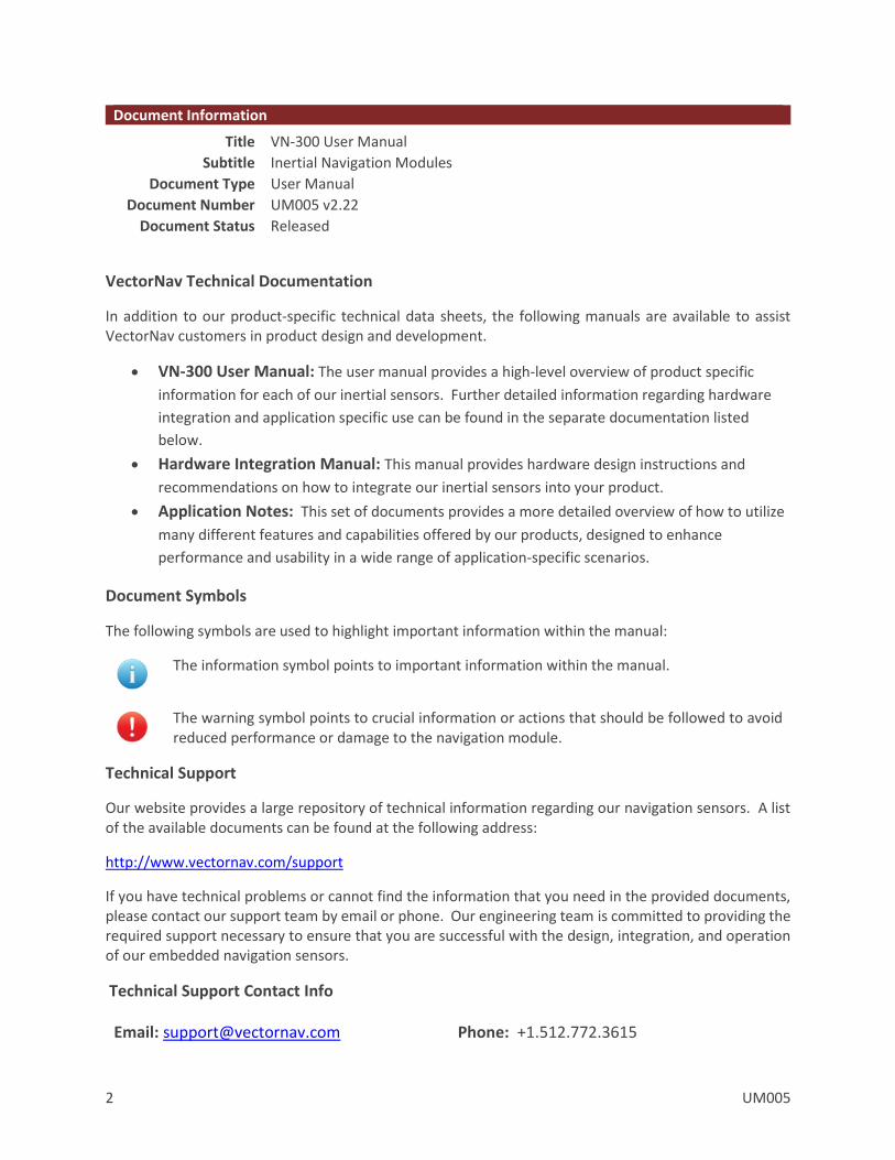
Document Information
Title VN-300 User Manual
Subtitle Inertial Navigation Modules
Document Type User Manual
Document Number UM005 v2.22
Document Status Released
VectorNav Technical Documentation
In addition to our product-specific technical data sheets, the following manuals are available to assist VectorNav customers in product design and development.
VN-300 User Manual: The user manual provides a high-level overview of product specific
information for each of our inertial sensors. Further detailed information regarding hardware
integration and application specific use can be found in the separate documentation listed
below.
Hardware Integration Manual: This manual provides hardware design instructions and
recommendations on how to integrate our inertial sensors into your product.
Application Notes: This set of documents provides a more detailed overview of how to utilize
many different features and capabilities offered by our products, designed to enhance
performance and usability in a wide range of application-specific scenarios.
Document Symbols
The following symbols are used to highlight important information within the manual:
The information symbol points to important information within the manual.
The warning symbol points to crucial information or actions that should be followed to avoid reduced performance or damage to the navigation module.
Technical Support
Our website provides a large repository of technical information regarding our navigation sensors. A list of the available documents can be found at the following address:
http://www.vectornav.com/support
If you have technical problems or cannot find the information that you need in the provided documents, please contact our support team by email or phone. Our engineering team is committed to providing the required support necessary to ensure that you are successful with the design, integration, and operation of our embedded navigation sensors.
Technical Support Contact Info
Email: [email protected] Phone: +1.512.772.3615

UM005 3
Table of Contents
1 Introduction 6
1.1 PRODUCT DESCRIPTION 6
1.2 FACTORY CALIBRATION 6
1.3 OPERATION OVERVIEW 6
1.4 GPS COMPASSING CAPABILITY 7
1.5 MEASUREMENT OUTPUT OPTIONS 7
1.6 PACKAGING OPTIONS 8
1.7 VN-300 PRODUCT CODES 10
2 Specifications 11
2.1 VN-300 SURFACE-MOUNT SENSOR (SMD) ELECTRICAL 11
2.2 VN-300 RUGGED ELECTRICAL 14
2.3 VN-300 SURFACE-MOUNT SENSOR (SMD) DIMENSIONS 16
2.4 VN-300 RUGGED DIMENSIONS 17
2.5 ABSOLUTE MAXIMUM RATINGS 17
2.6 SENSOR COORDINATE SYSTEM 18
3 VN-300 Software Architecture 20
3.1 IMU SUBSYSTEM 20
3.2 NAVSTATE SUBSYSTEM 23
3.3 NAVFILTER SUBSYSTEM 23
3.4 COMMUNICATION INTERFACE 25
3.5 COMMUNICATION PROTOCOL 25
3.6 SYSTEM ERROR CODES 27
3.7 CHECKSUM / CRC 28
4 Initial Setup and Operation 30
4.1 SETUP GPS ANTENNAS 30
4.2 SET THE GPS ANTENNA A OFFSET 31
4.3 ALIGN THE SENSOR TO THE VEHICLE 32
4.4 EXAMPLE GPS ANTENNA CONFIGURATION 33
4.5 CONFIGURE OUTPUTS 35
5 User Configurable Binary Output Messages 36
5.1 AVAILABLE OUTPUT TYPES 36
5.2 CONFIGURING THE OUTPUT TYPES 36
4 UM005
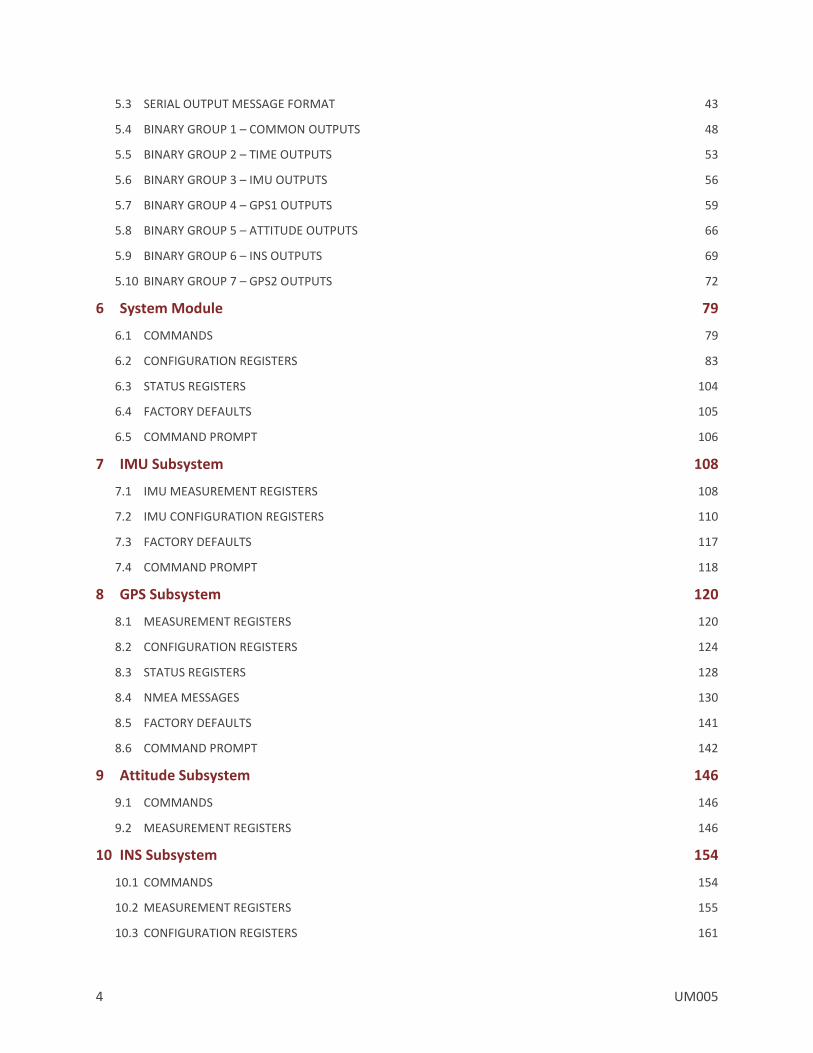
5.3 SERIAL OUTPUT MESSAGE FORMAT 43
5.4 BINARY GROUP 1 – COMMON OUTPUTS 48
5.5 BINARY GROUP 2 – TIME OUTPUTS 53
5.6 BINARY GROUP 3 – IMU OUTPUTS 56
5.7 BINARY GROUP 4 – GPS1 OUTPUTS 59
5.8 BINARY GROUP 5 – ATTITUDE OUTPUTS 66
5.9 BINARY GROUP 6 – INS OUTPUTS 69
5.10 BINARY GROUP 7 – GPS2 OUTPUTS 72
6 System Module 79
6.1 COMMANDS 79
6.2 CONFIGURATION REGISTERS 83
6.3 STATUS REGISTERS 104
6.4 FACTORY DEFAULTS 105
6.5 COMMAND PROMPT 106
7 IMU Subsystem 108
7.1 IMU MEASUREMENT REGISTERS 108
7.2 IMU CONFIGURATION REGISTERS 110
7.3 FACTORY DEFAULTS 117
7.4 COMMAND PROMPT 118
8 GPS Subsystem 120
8.1 MEASUREMENT REGISTERS 120
8.2 CONFIGURATION REGISTERS 124
8.3 STATUS REGISTERS 128
8.4 NMEA MESSAGES 130
8.5 FACTORY DEFAULTS 141
8.6 COMMAND PROMPT 142
9 Attitude Subsystem 146
9.1 COMMANDS 146
9.2 MEASUREMENT REGISTERS 146
10 INS Subsystem 154
10.1 COMMANDS 154
10.2 MEASUREMENT REGISTERS 155
10.3 CONFIGURATION REGISTERS 161

UM005 5
10.4 FACTORY DEFAULTS 163
11 Hard/Soft Iron Estimator Subsystem 164
11.1 CONFIGURATION REGISTERS 164
11.2 STATUS REGISTERS 165
11.3 FACTORY DEFAULTS 166
11.4 COMMAND PROMPT 167
12 World Magnetic & Gravity Module 170
12.1 CONFIGURATION REGISTERS 170
12.2 FACTORY DEFAULTS 172
12.3 COMMAND PROMPT 173

6 UM005
1 Introduction
1.1 Product Description
The VN-300 is a miniature, surface-mount, high-performance GPS-Aided Inertial Navigation System (GPS/INS). Incorporating the latest solid-state MEMS sensor technology, the VN-300 combines a set of 3-axis accelerometers, 3-axis gyros, 3-axis magnetometer, a barometric pressure sensor, two separate 50-channel L1 GPS receivers, as well as a 32-bit processor into a miniature aluminum enclosure. The VN-300 couples measurements from the onboard GPS receivers with measurements from the onboard inertial sensors to provide position, velocity, and attitude estimates of higher accuracies and with better dynamic performance than a standalone GPS receiver or AHRS. The VN-300 utilizes the two separate onboard GPS receivers to perform GPS interferometry utilizing the raw pseudo-range and carrier phase measurements to accurately estimate the heading of the vehicle. This powerful feature enables the VN-300 to accurately estimate heading with respect to true North, without any reliance on magnetic sensors, both in static and dynamic conditions.
1.2 Factory Calibration
MEMS inertial sensors are subject to several common sources of error: bias, scale factor, misalignments, temperature dependencies, and gyro g-sensitivity. All VN-300 sensors undergo a rigorous calibration process at the VectorNav factory to minimize these error sources. Compensation parameters calculated during these calibrations are stored on each individual sensor and digitally applied to the real-time measurements. Unlike the VN-100 and VN-200, the VN-300 is only available with the full thermal calibration option.
Thermal Calibration – this option extends the calibration process over multiple temperatures to ensure performance specifications are met over the full operating temperature range of -40 C to +85 C.
1.3 Operation Overview
The VN-300 has a built-in microprocessor that runs a robust INS Kalman Filter that estimates the position, velocity, and attitude of the sensor. The VN-300 INS filter couples position and velocity measurements from the onboard GPS module with inertial sensor measurements from the onboard accelerometers, gyroscopes, magnetometers, as well as the barometric pressure sensor. This coupling provides high accuracy attitude estimates when the sensor is subjected to dynamic motion and also provides position and velocity estimates at high output rates.
When the VN-300 is in motion, the VN-300 INS filter determines the attitude by comparing the position and velocity measurements to the onboard accelerometer measurements, and the magnetometer measurements are ignored by the INS filter. Compared to an AHRS, the heading accuracy is improved since the INS filter does not rely on measurements of Earth’s background magnetic field and magnetic disturbances no not have an effect on the attitude solution. In addition, the VN-300 pitch and roll estimates are robust to induced accelerations caused by dynamic motion of the sensor. Under static conditions, the heading angle is no longer observable based on only the correlation between the GPS position and velocity and the IMU accelerometer. For static and low-dynamic conditions the VN-300 utilizes GPS compassing techniques to derive accurate heading measurements, without any reliance on the magnetometer.
UM005 7
1.4 GPS Compassing Capability
The VN-300 differs from all other single GPS receiver INS systems, in that it has the capability to accurately estimate heading in both static and dynamic conditions by performing compassing on two separate GPS antennas. The VN-300 can estimate heading by comparing the raw pseudo-range and Doppler measurements between the two GPS antennas. The VN-300 is capable of measuring accurately (to within millimeters) the location of one antenna with respect to the other in an inertial (non-moving relative to Earth) frame of reference. If the VN-300 also knows the position of the two antennas relative to each other in the sensor’s (local body) frame, then it can calculate a heading angle in real-time with a high degree of accuracy. It is important to note that this heading measurement is derived directly from differencing the two GPS receiver measurements at a single point in time, and as such it is not dependent upon velocity, nor makes any assumptions to its direction. The accuracy is dependent only on the quality of the GPS signal, the distance between the two antennas, and the user’s measurement uncertainty in this distance measurement. With the distance between the two GPS antennas set to one meter that is accurately measured to better than 1 centimeter, the VN-300 is capable of estimating heading to within an average error of less than 0.5 degrees.
1.5 Measurement Output Options
Outputs from the VN-300 include:
Position Estimates in the following reference frames: o Latitude, Longitude, and Altitude o X, Y, Z position in Earth Centered Earth Fixed frame o X, Y, Z position in North, East, Down frame
Velocity Estimates in the following reference frames: o X, Y, Z velocities in Earth Centered Earth Fixed frame o X, Y, Z velocities in the North, East, Down frame
Attitude Estimates: o Yaw, Pitch, Roll o Quaternions o Rotation Matrix
INS Filter Uncertainties o Position, Velocity, & Attitude
GPS Time o GPS Time of Week o UTC Time
Angular Rate Measurements: o Bias compensated angular rates o Calibrated gyro measurements
Acceleration Measurements: o Bias compensated acceleration o Calibrated acceleration measurements o Gravity vector
Magnetic Measurements
Pressure Measurements / Altitude
8 UM005
1.6 Packaging Options
The VN-300 is available in two different configurations; a 30-pin surface mount package (VN-300 SMD) and an aluminum encased module (VN-300 Rugged). The VN-300 surface mount package is well suited for customers looking to integrate the VN-300 sensor at the electronics level while the VN-300 Rugged provides a precision enclosure with mounting tabs and alignment holes for a more off-the-shelf solution.
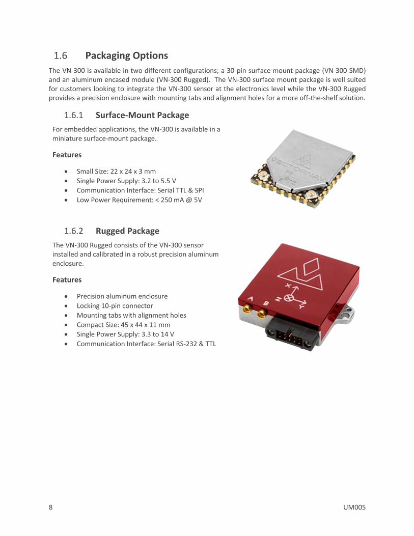
1.6.1 Surface-Mount Package
For embedded applications, the VN-300 is available in a miniature surface-mount package.
Features
Small Size: 22 x 24 x 3 mm
Single Power Supply: 3.2 to 5.5 V
Communication Interface: Serial TTL & SPI
Low Power Requirement: < 250 mA @ 5V
1.6.2 Rugged Package
The VN-300 Rugged consists of the VN-300 sensor installed and calibrated in a robust precision aluminum enclosure.
Features
Precision aluminum enclosure
Locking 10-pin connector
Mounting tabs with alignment holes
Compact Size: 45 x 44 x 11 mm
Single Power Supply: 3.3 to 14 V
Communication Interface: Serial RS-232 & TTL

UM005 9
1.6.3 VN-300 Surface Mount Development Kit
The VN-300 Development Kit provides the VN-300 surface-mount sensor installed onto a small PCB, providing easy access to all of the features and pins on the VN-300. Communication with the VN-300 is provided by USB and RS-232 serial communication ports. A 30-pin header provides easy access to each of the critical pins. The VN-300 Development Kit also includes all of the necessary cabling, documentation, and support software.
Features
Pre-installed VN-300 Sensor
Onboard USB->Serial converter
Onboard TTL->RS-232 converter
30-pin 0.1” header for access to VN-300 pins
Power supply jack – 5V (Can be powered from USB)
Board Size: 76 x 76 x 14 mm
1.6.4 VN-300 Rugged GPS/INS Development Kit
The VN-300 Rugged development kit includes the VN-300 Rugged sensor along with all of the necessary cabling required for operation. Two cables are provided in each development kit: one for RS-232 communication and a second custom cable with a built in USB converter. The devel-
opment kit also includes all of the relevant documentation and support software.
Features
VN-300 Rugged Sensor
10 ft RS-232 cable
6 ft USB connector cable
2x - 16 ft Magnetic Mount GPS Antennas
2x - MCX to SMA Antenna Adapters
Cable Connection Tool
CD w/Software Development Kit
User Manual, Quick Start Guide & Documentation
Carrying Case
10 UM005
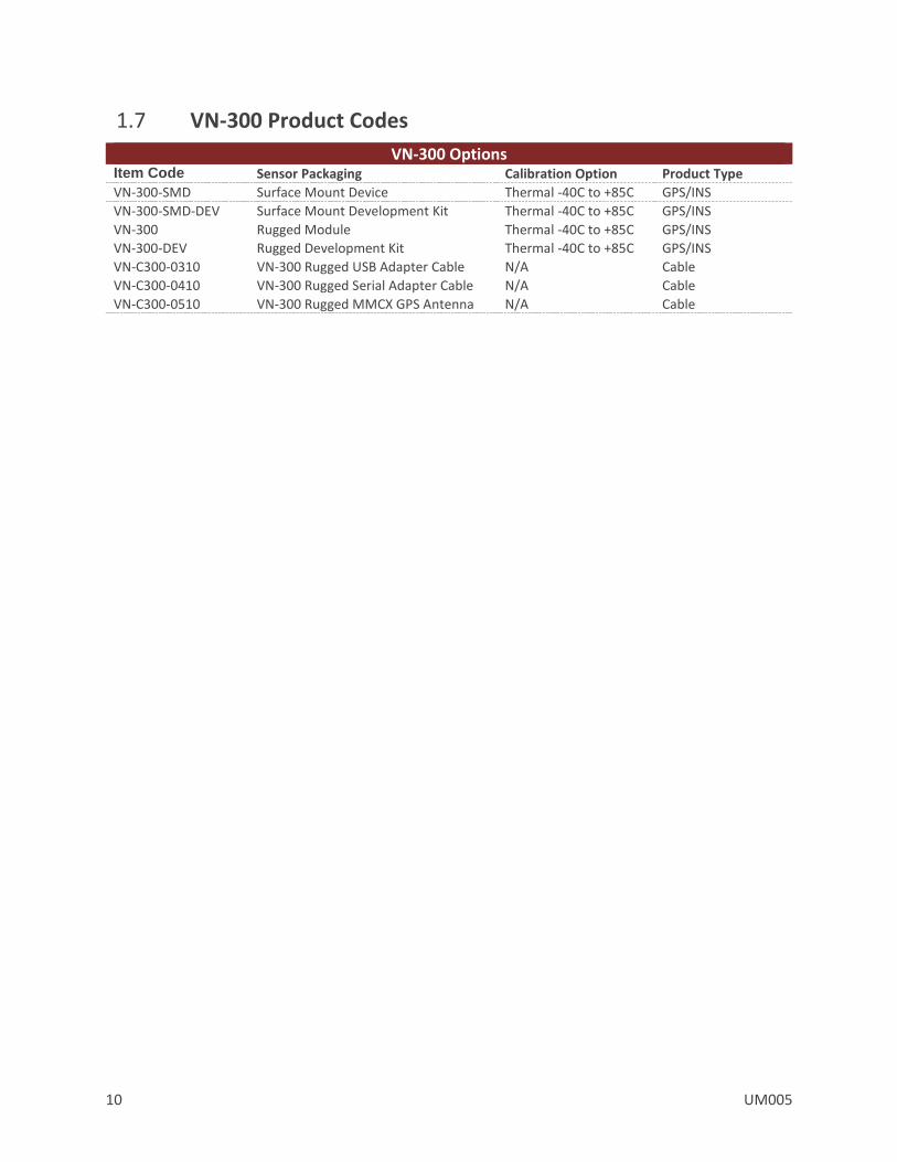
1.7 VN-300 Product Codes
VN-300 Options Item Code Sensor Packaging Calibration Option Product Type
VN-300-SMD Surface Mount Device Thermal -40C to +85C GPS/INS
VN-300-SMD-DEV Surface Mount Development Kit Thermal -40C to +85C GPS/INS
VN-300 Rugged Module Thermal -40C to +85C GPS/INS
VN-300-DEV Rugged Development Kit Thermal -40C to +85C GPS/INS
VN-C300-0310 VN-300 Rugged USB Adapter Cable N/A Cable
VN-C300-0410 VN-300 Rugged Serial Adapter Cable N/A Cable
VN-C300-0510 VN-300 Rugged MMCX GPS Antenna N/A Cable
UM005 11
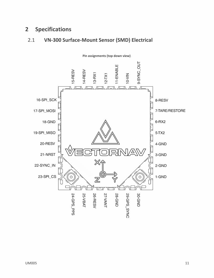
2 Specifications
2.1 VN-300 Surface-Mount Sensor (SMD) Electrical
Pin assignments (top down view)
12 UM005
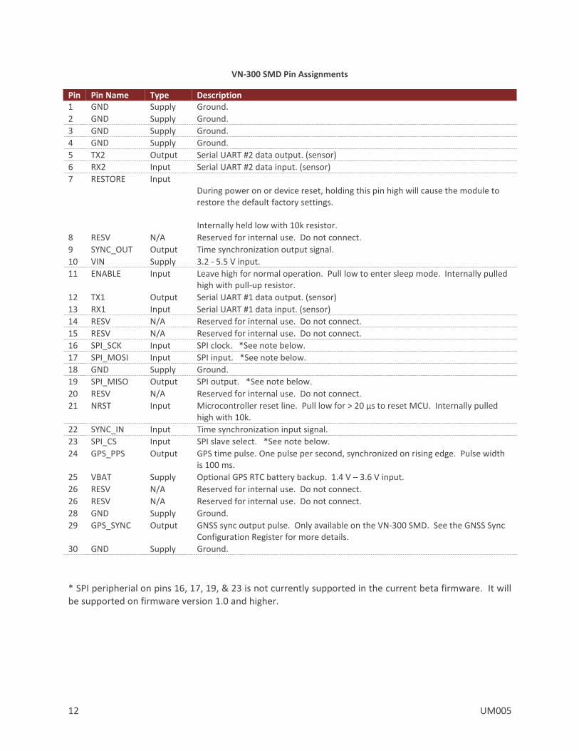
VN-300 SMD Pin Assignments
Pin Pin Name Type Description 1 GND Supply Ground.
2 GND Supply Ground.
3 GND Supply Ground.
4 GND Supply Ground.
5 TX2 Output Serial UART #2 data output. (sensor)
6 RX2 Input Serial UART #2 data input. (sensor)
7 RESTORE Input During power on or device reset, holding this pin high will cause the module to restore the default factory settings. Internally held low with 10k resistor.
8 RESV N/A Reserved for internal use. Do not connect.
9 SYNC_OUT Output Time synchronization output signal.
10 VIN Supply 3.2 - 5.5 V input.
11 ENABLE Input Leave high for normal operation. Pull low to enter sleep mode. Internally pulled high with pull-up resistor.
12 TX1 Output Serial UART #1 data output. (sensor)
13 RX1 Input Serial UART #1 data input. (sensor)
14 RESV N/A Reserved for internal use. Do not connect.
15 RESV N/A Reserved for internal use. Do not connect.
16 SPI_SCK Input SPI clock. *See note below.
17 SPI_MOSI Input SPI input. *See note below.
18 GND Supply Ground.
19 SPI_MISO Output SPI output. *See note below.
20 RESV N/A Reserved for internal use. Do not connect.
21 NRST Input Microcontroller reset line. Pull low for > 20 μs to reset MCU. Internally pulled high with 10k.
22 SYNC_IN Input Time synchronization input signal.
23 SPI_CS Input SPI slave select. *See note below.
24 GPS_PPS Output GPS time pulse. One pulse per second, synchronized on rising edge. Pulse width is 100 ms.
25 VBAT Supply Optional GPS RTC battery backup. 1.4 V – 3.6 V input.
26 RESV N/A Reserved for internal use. Do not connect.
26 RESV N/A Reserved for internal use. Do not connect.
28 GND Supply Ground.
29 GPS_SYNC Output GNSS sync output pulse. Only available on the VN-300 SMD. See the GNSS Sync Configuration Register for more details.
30 GND Supply Ground.
* SPI peripherial on pins 16, 17, 19, & 23 is not currently supported in the current beta firmware. It will be supported on firmware version 1.0 and higher.
UM005 13
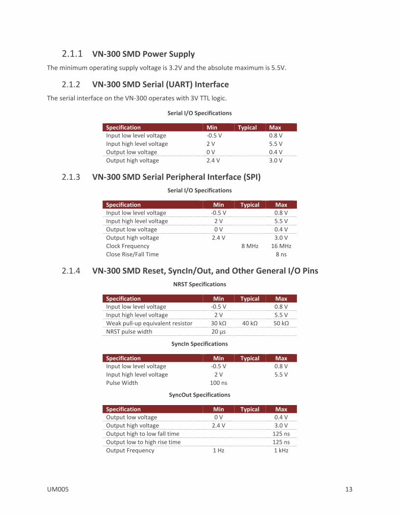
2.1.1 VN-300 SMD Power Supply
The minimum operating supply voltage is 3.2V and the absolute maximum is 5.5V.
2.1.2 VN-300 SMD Serial (UART) Interface
The serial interface on the VN-300 operates with 3V TTL logic.
Serial I/O Specifications
Specification Min Typical Max Input low level voltage -0.5 V 0.8 V
Input high level voltage 2 V 5.5 V
Output low voltage 0 V 0.4 V
Output high voltage 2.4 V 3.0 V
2.1.3 VN-300 SMD Serial Peripheral Interface (SPI)
Serial I/O Specifications
Specification Min Typical Max Input low level voltage -0.5 V 0.8 V
Input high level voltage 2 V 5.5 V
Output low voltage 0 V 0.4 V
Output high voltage 2.4 V 3.0 V
Clock Frequency 8 MHz 16 MHz
Close Rise/Fall Time 8 ns
2.1.4 VN-300 SMD Reset, SyncIn/Out, and Other General I/O Pins
NRST Specifications
Specification Min Typical Max Input low level voltage -0.5 V 0.8 V
Input high level voltage 2 V 5.5 V
Weak pull-up equivalent resistor 30 kΩ 40 kΩ 50 kΩ
NRST pulse width 20 μs
SyncIn Specifications
Specification Min Typical Max Input low level voltage -0.5 V 0.8 V
Input high level voltage 2 V 5.5 V
Pulse Width 100 ns
SyncOut Specifications
Specification Min Typical Max Output low voltage 0 V 0.4 V
Output high voltage 2.4 V 3.0 V
Output high to low fall time 125 ns
Output low to high rise time 125 ns
Output Frequency 1 Hz 1 kHz

14 UM005
2.2 VN-300 Rugged Electrical
VN-300 Rugged Pin Assignments
Pin Pin Name Description 1 VCC +3.3V to +14V
2 TX1 RS-232 voltage levels data output from the sensor. (Serial UART #1)
3 RX1 RS-232 voltage levels data input to the sensor. (Serial UART #1)
4 SYNC_OUT Output signal used for synchronization purposes. Software configurable to pulse when ADC, IMU, or attitude measurements are available.
5 GND Ground
6 RESTORE If high at reset, the device will restore to factory default state. Internally held low with 10k resistor.
7 SYNC_IN Input signal for synchronization purposes. Software configurable to either synchronize the measurements or the output with an external device.
8 TX2_TTL Serial UART #2 data output from the device at TTL voltage level (3V).
9 RX2_TTL Serial UART #2 data into the device at TTL voltage level (3V).
10 GPS_PPS GPS pulse per second output. This pin is a TTL voltage level (3V) output directly connected to the PPS (pulse per second) pin on GPS receiver A.
VN-300 Rugged External Connector
UM005 15
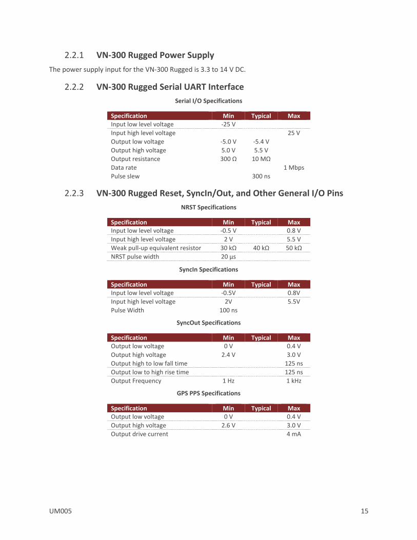
2.2.1 VN-300 Rugged Power Supply
The power supply input for the VN-300 Rugged is 3.3 to 14 V DC.
2.2.2 VN-300 Rugged Serial UART Interface
Serial I/O Specifications
Specification Min Typical Max Input low level voltage -25 V
Input high level voltage 25 V
Output low voltage -5.0 V -5.4 V
Output high voltage 5.0 V 5.5 V
Output resistance 300 Ω 10 MΩ
Data rate 1 Mbps
Pulse slew 300 ns
2.2.3 VN-300 Rugged Reset, SyncIn/Out, and Other General I/O Pins
NRST Specifications
Specification Min Typical Max Input low level voltage -0.5 V 0.8 V
Input high level voltage 2 V 5.5 V
Weak pull-up equivalent resistor 30 kΩ 40 kΩ 50 kΩ
NRST pulse width 20 μs
SyncIn Specifications
Specification Min Typical Max Input low level voltage -0.5V 0.8V
Input high level voltage 2V 5.5V
Pulse Width 100 ns
SyncOut Specifications
Specification Min Typical Max Output low voltage 0 V 0.4 V
Output high voltage 2.4 V 3.0 V
Output high to low fall time 125 ns
Output low to high rise time 125 ns
Output Frequency 1 Hz 1 kHz
GPS PPS Specifications
Specification Min Typical Max Output low voltage 0 V 0.4 V
Output high voltage 2.6 V 3.0 V
Output drive current 4 mA
16 UM005
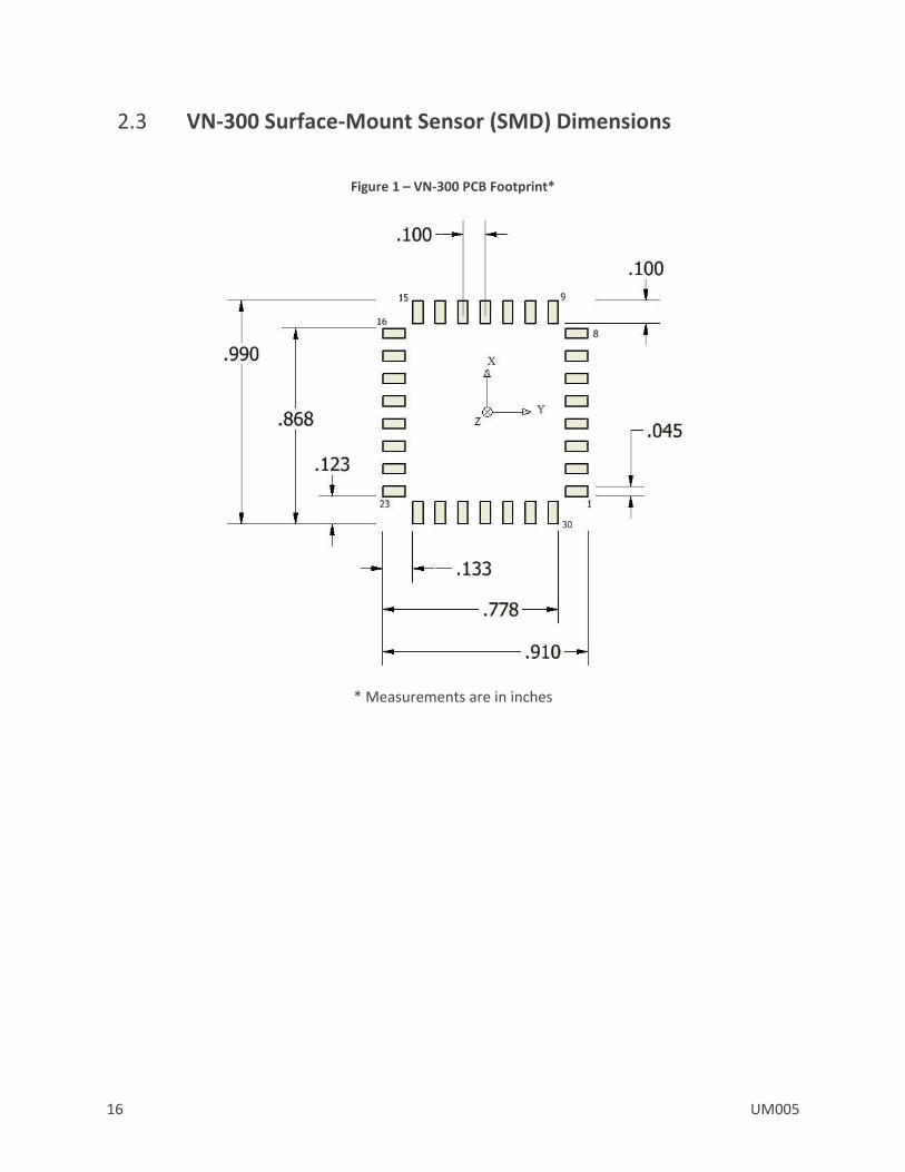
2.3 VN-300 Surface-Mount Sensor (SMD) Dimensions
Figure 1 – VN-300 PCB Footprint*
* Measurements are in inches

UM005 17
2.4 VN-300 Rugged Dimensions
2.4.1 Rugged Connector Type
The main connector used on the VN-300 Rugged is a 10-pin Harwin M80-5001042. The mating connector used on the cable assemblies provided by VectorNav for use with the VN-300 Rugged is a Harwin M80-4861005. The RF connector used on the VN-300 Rugged is a female MMCX jack.
2.5 Absolute Maximum Ratings
SMD Absolute Maximum Ratings
Specification Min Max Input Voltage -0.3 V 5.5 V
Operating Temperature -40 C 85 C
Storage Temperature -40 C 85 C
Rugged Absolute Maximum Ratings
Specification Min Max Input Voltage -0.3 V 14 V
Operating Temperature -40 C 85 C
Storage Temperature -40 C 85 C

18 UM005
2.6 Sensor Coordinate System
2.6.1 Sensor Coordinate Frame
The VN-300 uses a right-handed coordinate system. A positive yaw angle is defined as a positive right-handed rotation around the Z-axis. A positive pitch angle is defined as a positive right-handed rotation around the Y-axis. A positive roll angle is defined as a positive right-handed rotation around the X-axis. The axes direction with respect to the VN-300 module is shown in the figure below.
VN-300 Coordinate System
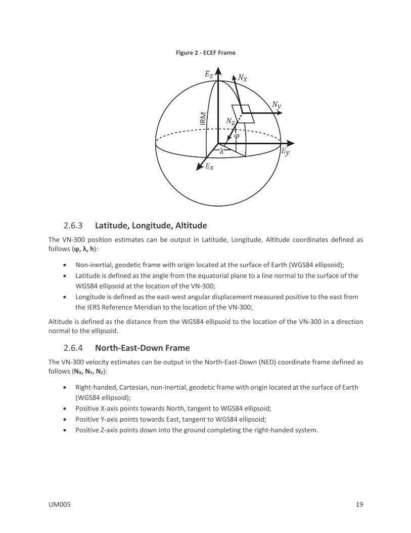
2.6.2 Earth Centered Earth Fixed Frame
The VN-300 position and velocity estimates can be output in the Earth-Centered-Earth-Fixed (ECEF) Frame defined as follows (EX, EY, EZ):
Right-handed, Cartesian, non-inertial frame with origin located at the center of Earth;
Fixed to and rotates with Earth;
Positive X-axis aligns with the WGS84 X-axis, which aligns with the International Earth Rotation and Reference Systems Service (IERS) Reference Meridian (IRM);
Positive Z-axis aligns with the WGS84 Z-axis, which aligns with the IERS Reference Pole (IRP) that points towards the North Pole;
Positive Y-axis aligns with the WGS84 Y-axis, completing the right-handed system.
UM005 19
Figure 2 - ECEF Frame
2.6.3 Latitude, Longitude, Altitude
The VN-300 position estimates can be output in Latitude, Longitude, Altitude coordinates defined as follows (ϕ, λ, h):
Non-inertial, geodetic frame with origin located at the surface of Earth (WGS84 ellipsoid);
Latitude is defined as the angle from the equatorial plane to a line normal to the surface of the
WGS84 ellipsoid at the location of the VN-300;
Longitude is defined as the east-west angular displacement measured positive to the east from
the IERS Reference Meridian to the location of the VN-300;
Altitude is defined as the distance from the WGS84 ellipsoid to the location of the VN-300 in a direction normal to the ellipsoid.
2.6.4 North-East-Down Frame
The VN-300 velocity estimates can be output in the North-East-Down (NED) coordinate frame defined as follows (NX, NY, NZ):
Right-handed, Cartesian, non-inertial, geodetic frame with origin located at the surface of Earth
(WGS84 ellipsoid);
Positive X-axis points towards North, tangent to WGS84 ellipsoid;
Positive Y-axis points towards East, tangent to WGS84 ellipsoid;
Positive Z-axis points down into the ground completing the right-handed system.
20 UM005
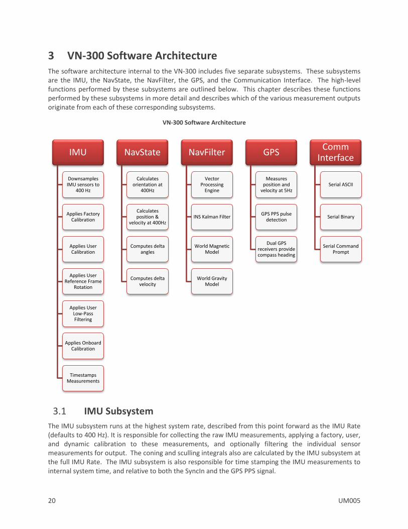
3 VN-300 Software Architecture The software architecture internal to the VN-300 includes five separate subsystems. These subsystems are the IMU, the NavState, the NavFilter, the GPS, and the Communication Interface. The high-level functions performed by these subsystems are outlined below. This chapter describes these functions performed by these subsystems in more detail and describes which of the various measurement outputs originate from each of these corresponding subsystems.
VN-300 Software Architecture
3.1 IMU Subsystem
The IMU subsystem runs at the highest system rate, described from this point forward as the IMU Rate (defaults to 400 Hz). It is responsible for collecting the raw IMU measurements, applying a factory, user, and dynamic calibration to these measurements, and optionally filtering the individual sensor measurements for output. The coning and sculling integrals also are calculated by the IMU subsystem at the full IMU Rate. The IMU subsystem is also responsible for time stamping the IMU measurements to internal system time, and relative to both the SyncIn and the GPS PPS signal.
IMU
Downsamples IMU sensors to
400 Hz
Applies Factory Calibration
Applies User Calibration
Applies User Reference Frame
Rotation
Applies User Low-Pass Filtering
Applies Onboard Calibration
Timestamps Measurements
NavState
Calculates orientation at
400Hz
Calculates position &
velocity at 400Hz
Computes delta angles
Computes delta velocity
NavFilter
Vector Processing
Engine
INS Kalman Filter
World Magnetic Model
World Gravity Model
GPS
Measures position and
velocity at 5Hz
GPS PPS pulse detection
Dual GPS receivers provide compass heading
Comm Interface
Serial ASCII
Serial Binary
Serial Command Prompt
UM005 21
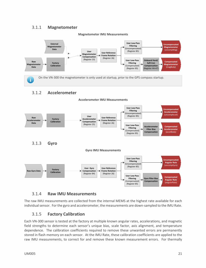
3.1.1 Magnetometer
Magnetometer IMU Measurements
On the VN-300 the magnetometer is only used at startup, prior to the GPS compass startup.
3.1.2 Accelerometer
Accelerometer IMU Measurements
3.1.3 Gyro
Gyro IMU Measurements
3.1.4 Raw IMU Measurements
The raw IMU measurements are collected from the internal MEMS at the highest rate available for each individual sensor. For the gyro and accelerometer, the measurements are down-sampled to the IMU Rate.
3.1.5 Factory Calibration
Each VN-300 sensor is tested at the factory at multiple known angular rates, accelerations, and magnetic field strengths to determine each sensor’s unique bias, scale factor, axis alignment, and temperature dependence. The calibration coefficients required to remove these unwanted errors are permanently stored in flash memory on each sensor. At the IMU Rate, these calibration coefficients are applied to the raw IMU measurements, to correct for and remove these known measurement errors. For thermally
Raw Magnetometer
Data
Factory Calibration
External Magnetometer
DataUser
Magnetometer Compensation(Register 23)
User Reference Frame Rotation
(Register 26)
User Low-Pass Filtering
(Uncompensated)(Register 85)
Onboard Hard/Soft Iron
Compensation(Register 44+47)
Uncompensated Magnetometer(uncompMag)
Compensated Magnetometer
(magBody)
User Low-Pass Filtering
(Compensated)(Register 85)
Raw Accelerometer
Data
Factory Calibration
User Accelerometer Compensation(Register 25)
User Reference Frame Rotation
(Register 26)
User Low-Pass Filtering
(Uncompensated)(Register 85)
Uncompensated Accelerometer(uncompAccel)
Compensated Accelerometer
(accelBody)
User Low-Pass Filtering
(Compensated)(Register 85)
Accelerometer Filter Bias
Compensation
Raw Gyro DataFactory
Calibration
User Gyro Compensation(Register 84)
User Reference Frame Rotation
(Register 26)
User Low-Pass Filtering
(Uncompensated)(Register 85)
Gyro Filter Bias Compensation
Uncompensated Angular Rate
(uncompGyro)
Compensated Angular Rate(angularRate)
User Low-Pass Filtering
(Compensated)(Register 85)
22 UM005
calibrated units the onboard temperature sensor is used to remove the measurement temperature dependence. The output of the factory calibration stage is referred to as the calibrated (but un-compensated) IMU measurements.
3.1.6 User Calibration
The VN-300 provides the user with the ability to apply a separate user calibration to remove additional bias, scale factor, and axis misalignments. The user calibration is applied after the factory calibration, and can be used to optionally fine tune the calibration for each of the individual sensors. The user calibration is optional and in most cases not required for normal operation.
3.1.7 User Reference Frame Rotation
The user reference frame rotation provides the user with the ability to apply a rigid body rotation to each of the sensor outputs. This can be used to transform the coordinate system of the onboard sensors into any other coordinate frame of the user’s choice. Since this transformation is applied to the IMU measurements prior to their use in the onboard attitude estimation algorithms, applying a user reference frame rotation will not only change the output coordinates for the IMU measurements, it will also change the IMU body frame for all subsequent attitude estimation calculations.
A write settings and reset command must be issued after setting the Reference Frame Rotation Register before coordinate transformation will be applied.
3.1.8 User Low-Pass Filtering
The VN-300 also provides a means (see Register 85) to apply low-pass filtering to the output compensated IMU measurements. It is important to note that the user low-pass filtering only applies to the output compensated IMU measurements. All onboard Kalman filters in the NavFilter subsystem always use the unfiltered IMU measurements after the User Reference Frame Rotation (Register 26) has been applied. As such the onboard Kalman filtering will not be affected by the user low-pass filter settings. The user low-pass filtering can be used to down-sample the output IMU measurements to ensure that information is not lost when the IMU measurements are sampled by the user at a lower rate than the internal IMU Rate.
3.1.9 Timestamp Measurements
All onboard measurements captured by the IMU subsystem are time stamped relative to several internal timing events. These events include the monotonically increasing system time (time since startup), the time since the last SyncIn event, and the time since the last GPS PPS pulse. These timestamps are recorded with microsecond resolution and ~10 microsecond accuracy relative to the onboard temperature compensated crystal oscillator. The onboard oscillator has a timing accuracy of ~20ppm over the temperature range of -40C to 80C.
3.1.10 Coning & Sculling
The IMU subsystem is also responsible for computing and accumulating the coning and sculling integrals. These integrals track the delta angle and delta velocity accumulated from one time step to another. The coning and sculling integrals are reset each time the delta angle and/or delta velocity are outputted (asynchronously) or polled from the delta theta and velocity register (Register 80). Between output and polling events, the coning and sculling integration are performed by the IMU subsystem at the IMU Rate.
UM005 23
3.2 NavState Subsystem
The NavState subsystem generates a continuous reliable stream of low-latency, low-jitter state outputs at a rate fixed to the IMU sample rate. The state outputs include any output such as attitude, position, and velocity, which are not directly measureable by the IMU and hence must be estimated by the onboard Kalman filters. The NavState runs immediately after, and in sync with the IMU subsystem, at a rate divisible into the IMU Rate. This rate is referred to as the NavState Rate (default 400 Hz). The NavState decouples the rate at which the state outputs are made available to the user from the rate at which they are being estimated by the onboard Kalman filters. This is very important for many applications which depend on low-latency, low-jitter attitude, position, and velocity measurements as inputs to their control loops. The NavState guarantees the output of new updated state information at a rate fixed to the IMU Rate with very low latency and output jitter. The NavState also provides the ability for the VN-300 to output estimated states at rates faster than the rate of the onboard Kalman filters, which may be affected by system load and input measurements availability.
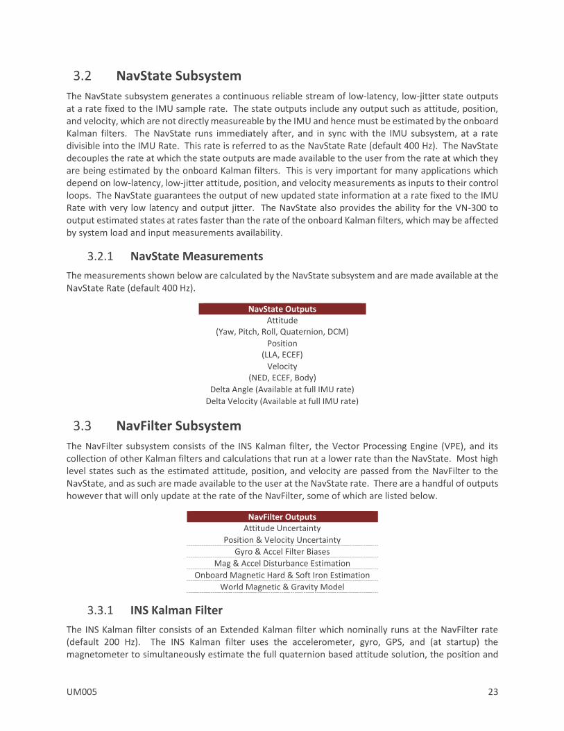
3.2.1 NavState Measurements
The measurements shown below are calculated by the NavState subsystem and are made available at the NavState Rate (default 400 Hz).
NavState Outputs Attitude
(Yaw, Pitch, Roll, Quaternion, DCM)
Position (LLA, ECEF)
Velocity (NED, ECEF, Body)
Delta Angle (Available at full IMU rate)
Delta Velocity (Available at full IMU rate)
3.3 NavFilter Subsystem
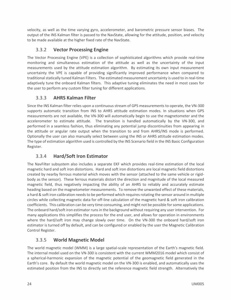
The NavFilter subsystem consists of the INS Kalman filter, the Vector Processing Engine (VPE), and its collection of other Kalman filters and calculations that run at a lower rate than the NavState. Most high level states such as the estimated attitude, position, and velocity are passed from the NavFilter to the NavState, and as such are made available to the user at the NavState rate. There are a handful of outputs however that will only update at the rate of the NavFilter, some of which are listed below.
NavFilter Outputs Attitude Uncertainty
Position & Velocity Uncertainty
Gyro & Accel Filter Biases
Mag & Accel Disturbance Estimation
Onboard Magnetic Hard & Soft Iron Estimation
World Magnetic & Gravity Model
3.3.1 INS Kalman Filter
The INS Kalman filter consists of an Extended Kalman filter which nominally runs at the NavFilter rate (default 200 Hz). The INS Kalman filter uses the accelerometer, gyro, GPS, and (at startup) the magnetometer to simultaneously estimate the full quaternion based attitude solution, the position and
24 UM005
velocity, as well as the time varying gyro, accelerometer, and barometric pressure sensor biases. The output of the INS Kalman filter is passed to the NavState, allowing for the attitude, position, and velocity to be made available at the higher fixed rate of the NavState.
3.3.2 Vector Processing Engine
The Vector Processing Engine (VPE) is a collection of sophisticated algorithms which provide real-time monitoring and simultaneous estimation of the attitude as well as the uncertainty of the input measurements used by the attitude estimation algorithm. By estimating its own input measurement uncertainty the VPE is capable of providing significantly improved performance when compared to traditional statically tuned Kalman Filters. The estimated measurement uncertainty is used to in real-time adaptively tune the onboard Kalman filters. This adaptive tuning eliminates the need in most cases for the user to perform any custom filter tuning for different applications.
3.3.3 AHRS Kalman Filter
Since the INS Kalman filter relies upon a continuous stream of GPS measurements to operate, the VN-300 supports automatic transition from INS to AHRS attitude estimation modes. In situations when GPS measurements are not available, the VN-300 will automatically begin to use the magnetometer and the accelerometer to estimate attitude. The transition is handled automatically by the VN-300, and performed in a seamless fashion, thus eliminating any potential jump discontinuities from appearing in the attitude or angular rate output when the transition to and from AHRS/INS mode is performed. Optionally the user can also manually select between using the INS or AHRS attitude estimation modes. The type of estimation algorithm used is controlled by the INS Scenario field in the INS Basic Configuration Register.
3.3.4 Hard/Soft Iron Estimator
The NavFilter subsystem also includes a separate EKF which provides real-time estimation of the local magnetic hard and soft iron distortions. Hard and soft iron distortions are local magnetic field distortions created by nearby ferrous material which moves with the sensor (attached to the same vehicle or rigid-body as the sensor). These ferrous materials distort the direction and magnitude of the local measured magnetic field, thus negatively impacting the ability of an AHRS to reliably and accurately estimate heading based on the magnetometer measurements. To remove the unwanted effect of these materials, a hard & soft iron calibration needs to be performed which requires rotating the sensor around in multiple circles while collecting magnetic data for off-line calculation of the magnetic hard & soft iron calibration coefficients. This calibration can be very time consuming, and might not be possible for some applications. The onboard hard/soft iron estimator runs in the background without requiring any user intervention. For many applications this simplifies the process for the end user, and allows for operation in environments where the hard/soft iron may change slowly over time. On the VN-300 the onboard hard/soft iron estimator is turned off by default, and can be configured or enabled by the user the Magnetic Calibration Control Register.
3.3.5 World Magnetic Model
The world magnetic model (WMM) is a large spatial-scale representation of the Earth’s magnetic field. The internal model used on the VN-300 is consistent with the current WMM2016 model which consist of a spherical-harmonic expansion of the magnetic potential of the geomagnetic field generated in the Earth’s core. By default the world magnetic model on the VN-300 is enabled, and automatically uses the estimated position from the INS to directly set the reference magnetic field strength. Alternatively the

UM005 25
world magnetic model can be manually used to calculate the magnetic field strength for a given latitude, longitude, altitude, and date which is then subsequently used as the fixed magnetic field reference strength. Control of the world magnetic model is performed using the Reference Vector Configuration Register.
3.3.6 World Gravity Model
The world gravity model (WGM) is a large spatial-scale representation of the Earth’s gravity potential as a function of position on the globe. The internal model used on the VN-300 is consistent with the Earth Gravity Model (EGM96), which consist of a spherical-harmonic expansion of the Earth’s geopotential. By default the world gravity model on the VN-300 is enabled, and automatically is set based on the estimated INS position. Control of the world gravity model is performed using the Reference Vector Configuration Register.
3.4 Communication Interface
The VN-300 provides two separate communication interfaces on two separate serial ports.
3.4.1 Serial Interface
The serial interface consists of two physically separate bi-directional UARTs. Each UART supports baud rates from 9600 bps up to a maximum of 921600 bps.
The rugged version includes an onboard TTL to RS-232 level shifter, thus at the 10-pin connector one serial port is offered with RS-232 voltages levels (Serial 1), while the other serial port (Serial 2) remains at 3V TTL logic levels.
It is important to note that the ability to update the firmware using the onboard bootloader is only supported on the serial port 1 interface. It is highly recommended that if serial port 1 is not used for normal operation, a means of accessing it is designed into the product to support future firmware updates.
3.4.2 SPI Interface
The SPI interface consists of a standard 4-wire synchronous serial data link which is capable of high data rates up to 16 Mbps. The VN-300 operates as slave on the bus enabled by the master using the slave select (SPI_CS) line. See the Basic Communication chapter for more information on the operation of the SPI interface.
3.5 Communication Protocol
The VN-300 utilizes a simple command based communication protocol for the serial interface. An ASCII protocol is used for command and register polling, and an optional binary interface is provided for streaming high speed real-time sensor measurements.
3.5.1 Serial ASCII
On the serial interface a full ASCII protocol provides support for all commands, and register polling. The ASCII protocol is very similar to the widely used NMEA 0183 protocol supported by most GPS receivers, and consists of comma delimited parameters printed in human readable text. Below is an example
26 UM005
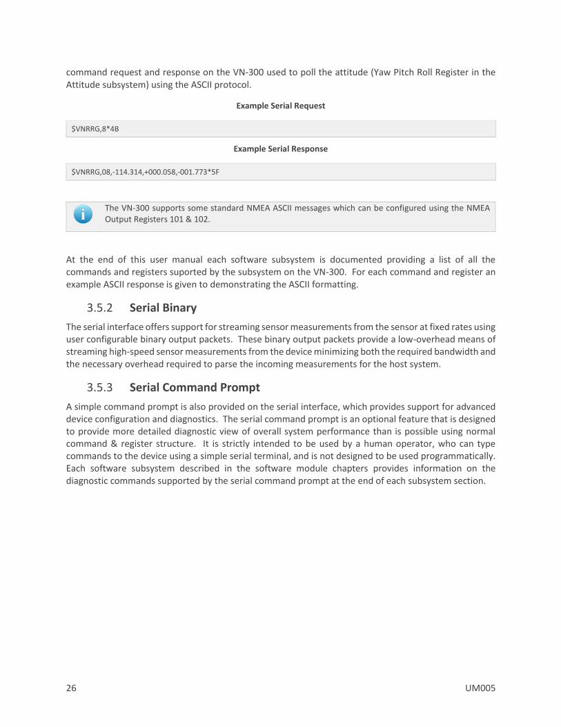
command request and response on the VN-300 used to poll the attitude (Yaw Pitch Roll Register in the Attitude subsystem) using the ASCII protocol.
Example Serial Request
$VNRRG,8*4B
Example Serial Response
$VNRRG,08,-114.314,+000.058,-001.773*5F
The VN-300 supports some standard NMEA ASCII messages which can be configured using the NMEA Output Registers 101 & 102.
At the end of this user manual each software subsystem is documented providing a list of all the commands and registers suported by the subsystem on the VN-300. For each command and register an example ASCII response is given to demonstrating the ASCII formatting.
3.5.2 Serial Binary
The serial interface offers support for streaming sensor measurements from the sensor at fixed rates using user configurable binary output packets. These binary output packets provide a low-overhead means of streaming high-speed sensor measurements from the device minimizing both the required bandwidth and the necessary overhead required to parse the incoming measurements for the host system.
3.5.3 Serial Command Prompt
A simple command prompt is also provided on the serial interface, which provides support for advanced device configuration and diagnostics. The serial command prompt is an optional feature that is designed to provide more detailed diagnostic view of overall system performance than is possible using normal command & register structure. It is strictly intended to be used by a human operator, who can type commands to the device using a simple serial terminal, and is not designed to be used programmatically. Each software subsystem described in the software module chapters provides information on the diagnostic commands supported by the serial command prompt at the end of each subsystem section.

UM005 27
3.6 System Error Codes
In the event of an error, the VN-300 will output $VNERR, followed by an error code. The possible error codes are listed in the table below with a description of the error.
Error Codes
Error Name Code Description Hard Fault 1 If this error occurs, then the firmware on the VN-300 has experienced a
hard fault exception. To recover from this error the processor will force a restart, and a discontinuity will occur in the serial output. The processor will restart within 50 ms of a hard fault error.
Serial Buffer Overflow 2 The processor’s serial input buffer has experienced an overflow. The processor has a 256 character input buffer.
Invalid Checksum 3 The checksum for the received command was invalid.
Invalid Command 4 The user has requested an invalid command.
Not Enough Parameters 5 The user did not supply the minimum number of required parameters for the requested command.
Too Many Parameters 6 The user supplied too many parameters for the requested command.
Invalid Parameter 7 The user supplied a parameter for the requested command which was invalid.
Invalid Register 8 An invalid register was specified.
Unauthorized Access 9 The user does not have permission to write to this register.
Watchdog Reset 10 A watchdog reset has occurred. In the event of a non-recoverable error the internal watchdog will reset the processor within 50 ms of the error.
Output Buffer Overflow 11 The output buffer has experienced an overflow. The processor has a 2048 character output buffer.
Insufficient Baud Rate 12 The baud rate is not high enough to support the requested asynchronous data output at the requested data rate.
Error Buffer Overflow 255 An overflow event has occurred on the system error buffer.
28 UM005
3.7 Checksum / CRC
The serial interface provides the option for either an 8-bit checksum or a 16-bit CRC. In the event neither the checksum nor the CRC is needed, both can be turned off by the user. Refer to the Communication Protocol Control Register for details on disabling the checksum/CRC.
3.7.1 Checksum Bypass
When communicating with the sensor using a serial terminal, the checksum calculation can be bypassed by replacing the hexadecimal digits in the checksum with uppercase X characters. This works for both the 8-bit and 16-bit checksum. An example command to read register 1 is shown below using the checksum bypass feature.
$VNRRG,1*XX
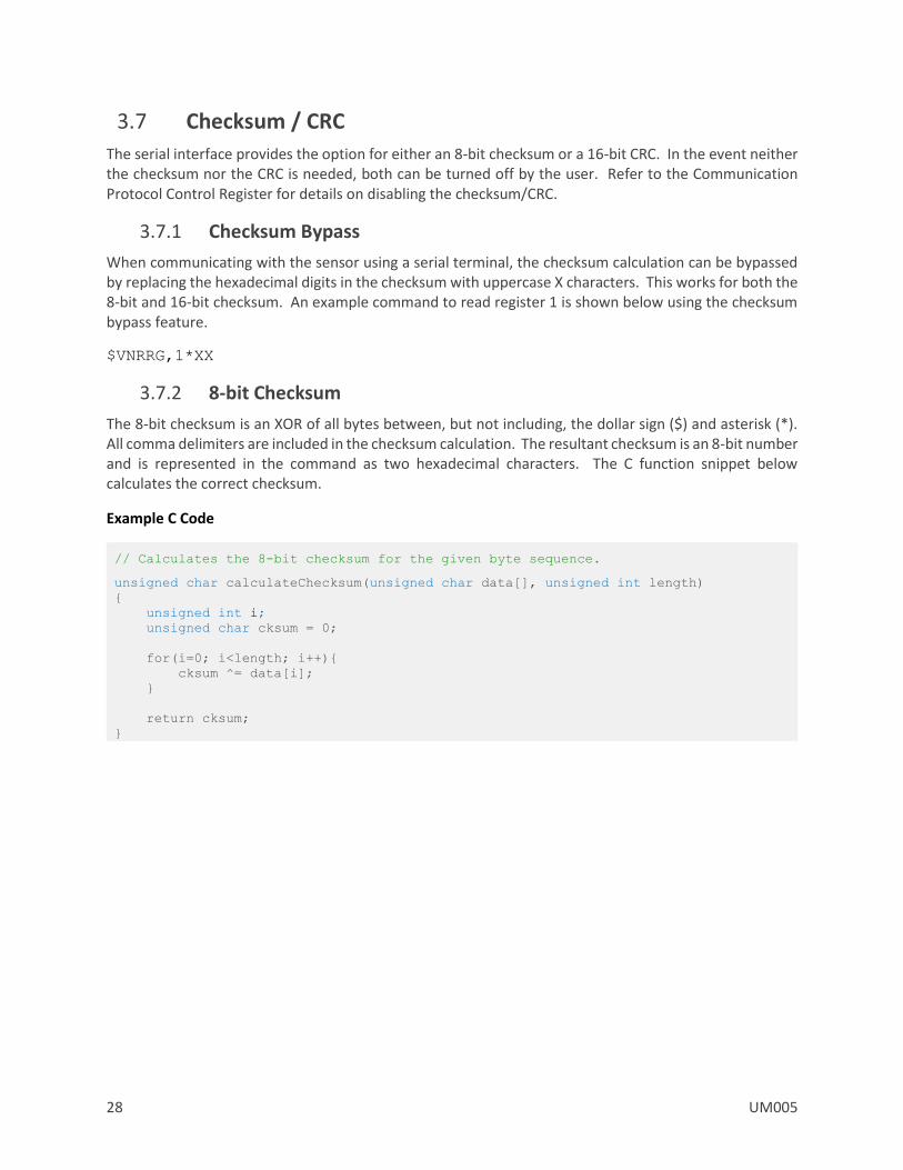
3.7.2 8-bit Checksum
The 8-bit checksum is an XOR of all bytes between, but not including, the dollar sign ($) and asterisk (*). All comma delimiters are included in the checksum calculation. The resultant checksum is an 8-bit number and is represented in the command as two hexadecimal characters. The C function snippet below calculates the correct checksum.
Example C Code
// Calculates the 8-bit checksum for the given byte sequence.
unsigned char calculateChecksum(unsigned char data[], unsigned int length)
unsigned int i;
unsigned char cksum = 0;
for(i=0; i<length; i++)
cksum ^= data[i];
return cksum;
UM005 29
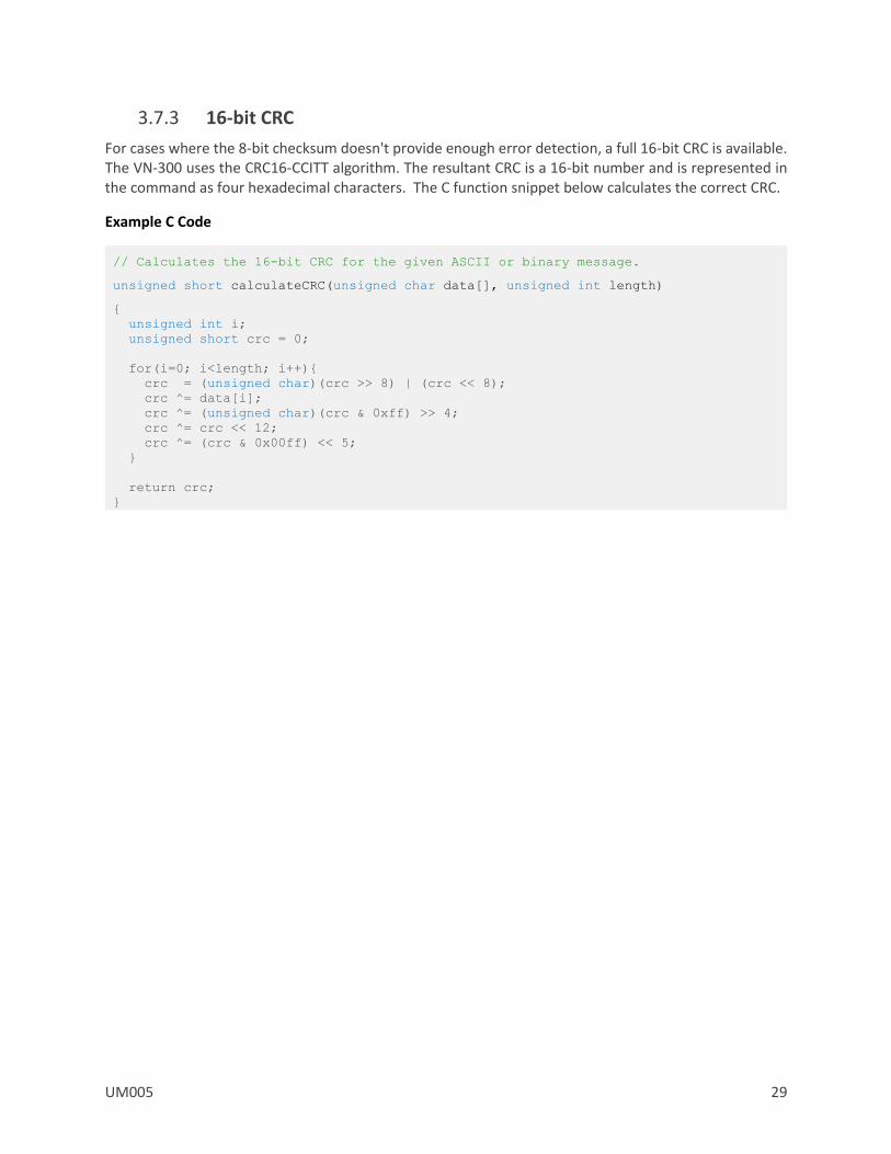
3.7.3 16-bit CRC
For cases where the 8-bit checksum doesn't provide enough error detection, a full 16-bit CRC is available. The VN-300 uses the CRC16-CCITT algorithm. The resultant CRC is a 16-bit number and is represented in the command as four hexadecimal characters. The C function snippet below calculates the correct CRC.
Example C Code
// Calculates the 16-bit CRC for the given ASCII or binary message.
unsigned short calculateCRC(unsigned char data[], unsigned int length)
unsigned int i;
unsigned short crc = 0;
for(i=0; i<length; i++)
crc = (unsigned char)(crc >> 8) | (crc << 8);
crc ^= data[i];
crc ^= (unsigned char)(crc & 0xff) >> 4;
crc ^= crc << 12;
crc ^= (crc & 0x00ff) << 5;
return crc;
30 UM005
4 Initial Setup and Operation The VN-300 INS has been designed to require minimal configuration by the end user for normal operation. This section provides a high-level overview of the recommended steps that the end user should follow to ensure proper operation of the VN-300 for the application. If you are using the product for the first time, it is recommended that you follow the GPS Compass – INS Initial Setup Guide (AN017) that is provided with the product, as it will provide a more detailed step-by-step guide demonstrating how to properly configure the sensor for first time use.
4.1 Setup GPS Antennas
The first step prior to using the product is to determine how the two GPS antennas will be mounted on your vehicle or other platform. The accuracy of the heading measurement is inversely proportional to the distance between the two antennas. With nominal conditions (good GPS availability) the VN-300 can accurately achieve a heading accuracy of less than 0.5 degrees with a distance between the GPS antennas (baseline length) of 1 meter. The VN-300 can operate with baseline lengths as low as a few centimeters; however the static heading accuracy will scale with the antenna separation distance by approximately (0.3 degrees RMS)/(baseline length in meters). For example, a 0.5 meter baseline will provide a static heading accuracy of 0.6 degrees RMS and a 0.25 meter baseline will provide 1.2 degrees RMS. The decrease in accuracy typically levels off around 1.5 to 2.0 degrees RMS for baseline lengths below 20 centimeters. In its factory default state the VN-300 defaults to a 1 meter baseline, although the user can adjust this baseline to any value using the GPS Compass Baseline Register in the GPS subsystem.
4.1.1 GPS Compass Baseline (Factory Default)
As mentioned previously, the VN-300 has a factory default baseline of 1, 0, 0 [m]. This vector represents the position of a point on GPS antenna B relative to the same point on GPS antenna A in the output coordinate system on the VN-300. The default output coordinate system is engraved on the top of the aluminum enclosure. For the factory default case, GPS antenna B should be positioned in front of GPS antenna A relative to the X-axis marked on the VN-300 enclosure as shown in the figure below. If a different baseline length or direction required, then you will need to write the new baseline vector and the measurement uncertainty to the sensor using the GPS Compass Baseline Register.

UM005 31
GPS Compass Baseline
4.1.2 Baseline Measurement Accuracy
It is important the user attempt to measure the distance between the two antennas in each of the three axes as accurately as possible, as the overall heading accuracy of the VN-300 will depend upon the accuracy of this measurement. More specifically the heading accuracy is linearly proportional to the measurement accuracy of the position of GPS antenna B with respect to GPS antenna A, and inversely proportional to the baseline length.
Heading Error [deg] ~= 0.57 * (Baseline Error [cm]) / (Baseline Length [m])
On a 1 meter baseline, a 1 cm measurement error equates to heading error of 0.6 degrees.
It is recommended that you do not attempt to measure between the centers of the two antennas. Instead you should measure to more distinguishable point such as the edge of the antenna where the rubber boot mates to the plastic shroud, as this will result in a more repeatable and accurate measurement.
It is very important that the two antennas are oriented in the same direction relative to each other. The RF phase center of the GPS antenna isn’t always located at the geometric center, thus aligning the antennas in the same direction will ensure that our measurement between two geometric points on the antennas is equivalent to the distance between the two antennas RF phase centers.
4.2 Set the GPS Antenna A Offset
During periods of motion the INS needs to properly account for the relative motion of the primary GPS antenna (antenna A) with respect to the IMU. In the factory default state the VN-300 assumes that the

32 UM005
GPS antenna A is co-located at the same position (to within 10 centimeters) as GPS antenna A. If the distance between the VN-300 and the primary GPS antenna (antenna A) is more than 10 centimeters, then you should measure this offset vector and set it using the GPS Antenna A Offset Register.
Design Rule of Thumb
Error in the measured GPS antenna A offset vector has a weaker impact on the overall heading accuracy than that of the GPS baseline vector. The table below shows how the overall heading accuracy is affected by different amounts of error in the measured GPS antenna A offset vector.
GPS Antenna A Offset Measurement Error [cm]
Best Obtainable Heading Accuracy[deg]
< 10 ~ 0.3 deg
10 - 50 ~ 0.5 deg
50 - 100 ~ 1.0 deg
When the distance between the VN-300 IMU and the GPS antenna A is less than 10 centimeters, it is safe to use the factory default value for this offset of 0, 0, 0. For offsets above 10 centimeters it is recommended that you measure this offset and set it using the GPS Antenna A Offset register.
4.3 Align the Sensor to the Vehicle
By default the VN-300 will output the heading, pitch, and roll with respect to the sensor’s reference frame which is engraved on the top of the VN-300 aluminum enclosure. To ensure that the output is consistent with the attitude of the vehicle the sensor is attached to you will need to align the sensor on the vehicle such that the X-axis points out the front of the vehicle (bow), the Y-axis points out the right (starboard), and the Z-axis points down. If it is not possible to orient the sensor in this configuration with respect to the vehicle, then you will need to use the Reference Frame Rotation Register to set the relative orientation of the IMU with respect to the vehicle. This register can also optionally be used by the user to take into account small known misalignment errors of the IMU with respect to the vehicle.
UM005 33
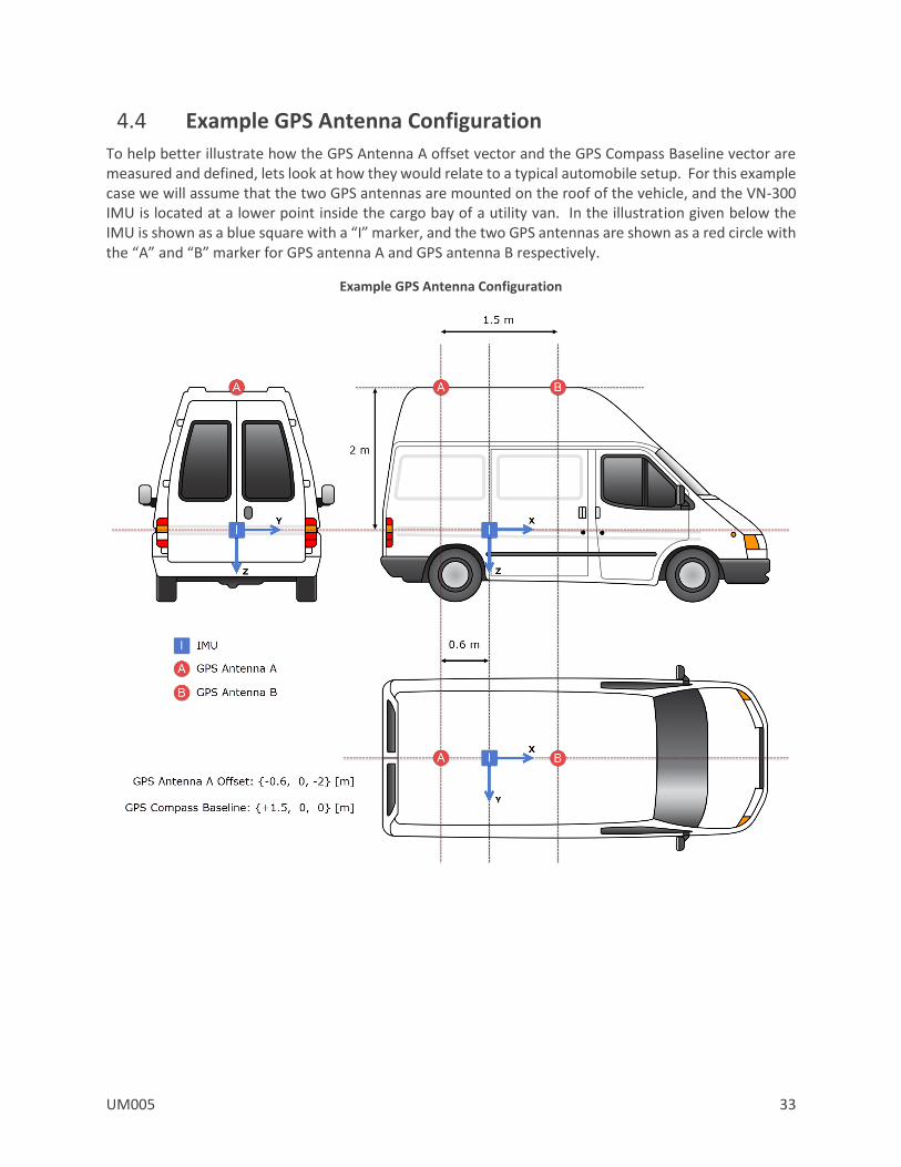
4.4 Example GPS Antenna Configuration
To help better illustrate how the GPS Antenna A offset vector and the GPS Compass Baseline vector are measured and defined, lets look at how they would relate to a typical automobile setup. For this example case we will assume that the two GPS antennas are mounted on the roof of the vehicle, and the VN-300 IMU is located at a lower point inside the cargo bay of a utility van. In the illustration given below the IMU is shown as a blue square with a “I” marker, and the two GPS antennas are shown as a red circle with the “A” and “B” marker for GPS antenna A and GPS antenna B respectively.
Example GPS Antenna Configuration

34 UM005
In summary, for this setup the user will need to make two measurements:
Measurement #1:
Measure the position of GPS antenna A relative to the VN-300 IMU. This measurement is a 3D vector measured in the frame of reference of the IMU output frame. In the case no reference frame rotation is used (factory default), the IMU output frame is the one that is engraved on the VN-300 aluminum enclosure. For automotive applications the X-axis should point out the front of the vehicle, the Y-axis should point out the passenger side, and the Z-axis should point down toward the pavement.
The position of the GPS antenna A with respect to the VN-300 IMU is known as the GPS Antenna A offset, and for this setup it is equal to -0.6, 0, -2 [m]. Once this measurement is made, the user will can either set this using Sensor Explorer (VectorNav’s Configuration GUI application), or by simply sending the following ASCII message to the VN-300:
$VNWRG,57,-0.6,0,2*XX
The above command writes the values -0.6, 0, 2 to register 57 which corresponds to the GPS Antenna A Offset register.
Measurement #2:
The second measurement that needs to be made is the position of GPS antenna B relative to GPS antenna A. This measurement also needs to be made relative the IMU output frame, and for this setup it is equal to +1.5, 0, 0 [m]. Once this measurement is made, the user can either set this using Sensor Explorer, or by simply sending the following ASCII message to the VN-300:
$VNWRG,93,1.5,0,0,0.038,0.038,0.038*XX
The above command writes the values +1.5, 0, 0 to the GPS Compass Baseline Register in the GPS subsystem section along with the uncertainties values of 0.038, 0.038, 0.038.
In this example we have scaled the default uncertainty values of 0.0254, 0.0254, 0.0254 by a factor of 1.5 to adjust for the longer baseline length. It is highly recommended that this type of scaling be performed for any baseline longer than the default of 1.0m.
Once these two measurements have been set on the VN-300, you will need to instruct the VN-300 to save these values to flash memory so that they will take effect upon startup. To do this you can issue a “Write Settings” command from Sensor Explorer or by simply sending the following ASCII command to the VN-300:
$VNWNV*XX
At this point your VN-300 is properly configured and ready for operation.
UM005 35
4.5 Configure Outputs
Under the default configuration settings, the VN-300 will output the INS Solution LLA ASCII message, which includes the GPS Time of Week, GPS Week, INS Status, heading, pitch, roll, lattitude, longitude, altitude, velocity in North East Down, and the solution uncertainty as human readable ASCII messages at a rate of 40Hz. The message format for this message is described in detail in the INS Solution LLA register of the INS subsystem section.
The VN-300 provides two different means of obtaining measurements, using either human readable ASCII messages, or user configurable custom binary output messages.
Human Readable ASCII Messages
The VN-300 provides a variety of measurement output combinations which can be selected using the Asynchronous Output Register. The rate of the output can be adjusted from 1 to 200 message per second using the Asynchronous Output Frequency Register. Each different ASCII output message type has its own unique 5 character heading so that it can easily be distinguished in the data stream.
User Configurable Binary Output Messages
Alternatively for higher rate data, or custom message outputs, the VN-300 also supports the ability to construct your own binary output messages. This option provides the user with the ability to select a subset of any of the available measurements that the VN-300 offers, and have it packaged into a single compact binary packet provided at any rate from 1 to 400 times per second. Up to 3 different custom messages can be created, each with its own separate output rate, and configured to output over one or both of the serial ports.
36 UM005
5 User Configurable Binary Output Messages The VN-300 supports 3 separate user configurable binary output messages available on the serial interface. Each message can be configured by the user to contain any of the available output measurement types from the IMU, NavState, NavFilter, or the GPS subsystems. The device can be configured to asynchronously output each message at a fixed rate based upon a divisor of the IMU internal sampling rate (IMU Rate).
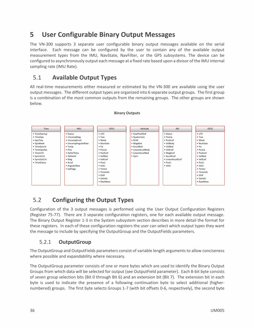
5.1 Available Output Types
All real-time measurements either measured or estimated by the VN-300 are available using the user output messages. The different output types are organized into 6 separate output groups. The first group is a combination of the most common outputs from the remaining groups. The other groups are shown below.
Binary Outputs
5.2 Configuring the Output Types
Configuration of the 3 output messages is performed using the User Output Configuration Registers (Register 75-77). There are 3 separate configuration registers, one for each available output message. The Binary Output Register 1-3 in the System subsystem section describes in more detail the format for these registers. In each of these configuration registers the user can select which output types they want the message to include by specifying the OutputGroup and the OutputFields parameters.
5.2.1 OutputGroup
The OutputGroup and OutputFields parameters consist of variable length arguments to allow conciseness where possible and expandability where necessary.
The OutputGroup parameter consists of one or more bytes which are used to identify the Binary Output Groups from which data will be selected for output (see OutputField parameter). Each 8-bit byte consists of seven group selection bits (Bit 0 through Bit 6) and an extension bit (Bit 7). The extension bit in each byte is used to indicate the presence of a following continuation byte to select additional (higher-numbered) groups. The first byte selects Groups 1-7 (with bit offsets 0-6, respectively), the second byte
Time
• TimeStartup
• TimeGps
• GpsTow
• GpsWeek
• TimeSyncIn
• TimeGpsPps
• TimeUTC
• SyncInCnt
• SyncOutCnt
• TimeStatus
IMU
• Status
• UncompMag
• UncompAccel
• UncompAngularRate
• Temp
• Pres
• DeltaTheta
• DeltaVel
• Mag
• Accel
• AngularRate
• SatFlags
GPS1
• UTC
• Tow
• Week
• NumSats
• Fix
• PosLla
• PosEcef
• VelNed
• VelEcef
• PosU
• VelU
• TimeU
• TimeInfo
• DOP
• SatInfo
• RawMeas
Attitude
• YawPitchRoll
• Quaternion
• DCM
• MagNed
• AccelNed
• LinearAccelBody
• LinearAccelNed
• YprU
INS
• Status
• PosLla
• PosEcef
• VelBody
• VelNed
• VelEcef
• MagEcef
• AccelEcef
• LinearAccelEcef
• PosU
• VelU
GPS2
• UTC
• Tow
• Week
• NumSats
• Fix
• PosLla
• PosEcef
• VelNed
• VelEcef
• PosU
• VelU
• TimeU
• TimeInfo
• DOP
• SatInfo
• RawMeas
UM005 37
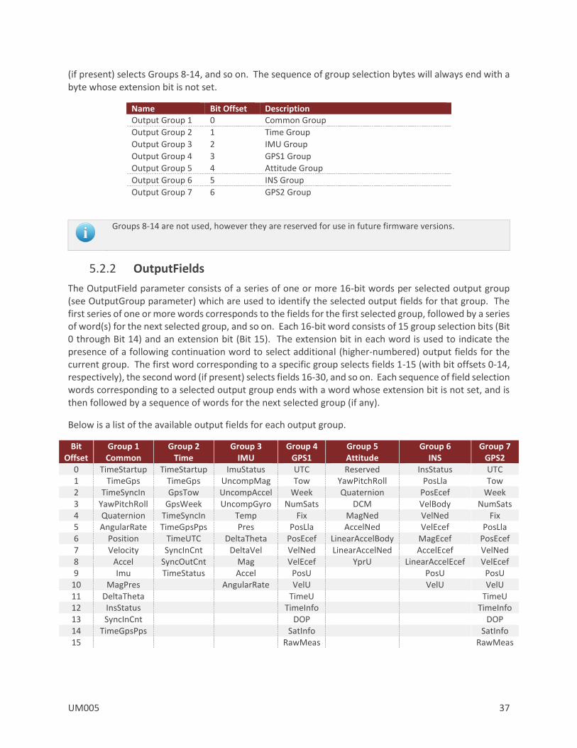
(if present) selects Groups 8-14, and so on. The sequence of group selection bytes will always end with a byte whose extension bit is not set.
Name Bit Offset Description Output Group 1 0 Common Group
Output Group 2 1 Time Group
Output Group 3 2 IMU Group
Output Group 4 3 GPS1 Group
Output Group 5 4 Attitude Group
Output Group 6 5 INS Group
Output Group 7 6 GPS2 Group
Groups 8-14 are not used, however they are reserved for use in future firmware versions.
5.2.2 OutputFields
The OutputField parameter consists of a series of one or more 16-bit words per selected output group (see OutputGroup parameter) which are used to identify the selected output fields for that group. The first series of one or more words corresponds to the fields for the first selected group, followed by a series of word(s) for the next selected group, and so on. Each 16-bit word consists of 15 group selection bits (Bit 0 through Bit 14) and an extension bit (Bit 15). The extension bit in each word is used to indicate the presence of a following continuation word to select additional (higher-numbered) output fields for the current group. The first word corresponding to a specific group selects fields 1-15 (with bit offsets 0-14, respectively), the second word (if present) selects fields 16-30, and so on. Each sequence of field selection words corresponding to a selected output group ends with a word whose extension bit is not set, and is then followed by a sequence of words for the next selected group (if any).
Below is a list of the available output fields for each output group.
Bit Offset
Group 1 Common
Group 2 Time
Group 3 IMU
Group 4 GPS1
Group 5 Attitude
Group 6 INS
Group 7 GPS2
0 TimeStartup TimeStartup ImuStatus UTC Reserved InsStatus UTC 1 TimeGps TimeGps UncompMag Tow YawPitchRoll PosLla Tow 2 TimeSyncIn GpsTow UncompAccel Week Quaternion PosEcef Week 3 YawPitchRoll GpsWeek UncompGyro NumSats DCM VelBody NumSats 4 Quaternion TimeSyncIn Temp Fix MagNed VelNed Fix 5 AngularRate TimeGpsPps Pres PosLla AccelNed VelEcef PosLla 6 Position TimeUTC DeltaTheta PosEcef LinearAccelBody MagEcef PosEcef 7 Velocity SyncInCnt DeltaVel VelNed LinearAccelNed AccelEcef VelNed 8 Accel SyncOutCnt Mag VelEcef YprU LinearAccelEcef VelEcef 9 Imu TimeStatus Accel PosU PosU PosU
10 MagPres AngularRate VelU VelU VelU 11 DeltaTheta TimeU TimeU 12 InsStatus TimeInfo TimeInfo 13 SyncInCnt DOP DOP 14 TimeGpsPps SatInfo SatInfo 15 RawMeas RawMeas
38 UM005
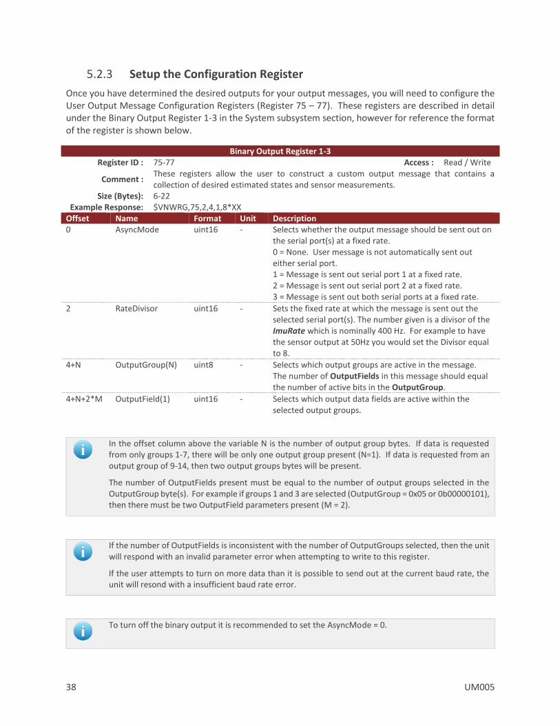
5.2.3 Setup the Configuration Register
Once you have determined the desired outputs for your output messages, you will need to configure the User Output Message Configuration Registers (Register 75 – 77). These registers are described in detail under the Binary Output Register 1-3 in the System subsystem section, however for reference the format of the register is shown below.
Binary Output Register 1-3 Register ID : 75-77 Access : Read / Write
Comment : These registers allow the user to construct a custom output message that contains a collection of desired estimated states and sensor measurements.
Size (Bytes): 6-22 Example Response: $VNWRG,75,2,4,1,8*XX
Offset Name Format Unit Description 0 AsyncMode uint16 - Selects whether the output message should be sent out on
the serial port(s) at a fixed rate. 0 = None. User message is not automatically sent out either serial port. 1 = Message is sent out serial port 1 at a fixed rate. 2 = Message is sent out serial port 2 at a fixed rate. 3 = Message is sent out both serial ports at a fixed rate.
2 RateDivisor uint16 - Sets the fixed rate at which the message is sent out the selected serial port(s). The number given is a divisor of the ImuRate which is nominally 400 Hz. For example to have the sensor output at 50Hz you would set the Divisor equal to 8.
4+N OutputGroup(N) uint8 - Selects which output groups are active in the message. The number of OutputFields in this message should equal the number of active bits in the OutputGroup.
4+N+2*M OutputField(1) uint16 - Selects which output data fields are active within the selected output groups.
In the offset column above the variable N is the number of output group bytes. If data is requested from only groups 1-7, there will be only one output group present (N=1). If data is requested from an output group of 9-14, then two output groups bytes will be present.
The number of OutputFields present must be equal to the number of output groups selected in the OutputGroup byte(s). For example if groups 1 and 3 are selected (OutputGroup = 0x05 or 0b00000101), then there must be two OutputField parameters present (M = 2).
If the number of OutputFields is inconsistent with the number of OutputGroups selected, then the unit will respond with an invalid parameter error when attempting to write to this register.
If the user attempts to turn on more data than it is possible to send out at the current baud rate, the unit will resond with a insufficient baud rate error.
To turn off the binary output it is recommended to set the AsyncMode = 0.
UM005 39
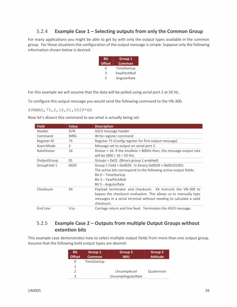
5.2.4 Example Case 1 – Selecting outputs from only the Common Group
For many applications you might be able to get by with only the output types available in the common group. For these situations the configuration of the output message is simple. Suppose only the following information shown below is desired.
Bit Offset
Group 1 Common
0 TimeStartup
3 YawPitchRoll
5 AngularRate
For this example we will assume that the data will be polled using serial port 2 at 50 Hz.
To configure this output message you would send the following command to the VN-300.
$VNWRG,75,2,16,01,0029*XX
Now let’s dissect this command to see what is actually being set:
Field Value Description Header $VN ASCII message header
Command WRG Write register command
Register ID 75 Register 75 (Config register for first output message)
AsyncMode 2 Message set to output on serial port 2.
RateDivisor 16 Divisor = 16. If the ImuRate = 800Hz then, the message output rate will be (800 / 16 = 50 Hz).
OutputGroup 01 Groups = 0x01. (Binary group 1 enabled)
GroupField 1 0029 Group 1 Field = 0x0029. In binary 0x0029 = 0b00101001. The active bits correspond to the following active output fields: Bit 0 – TimeStartup Bit 3 – YawPitchRoll Bit 5 - AngularRate
Checksum XX Payload terminator and checksum. XX instructs the VN-300 to bypass the checksum evaluation. This allows us to manually type messages in a serial terminal without needing to calculate a valid checksum.
End Line \r\n Carriage return and line feed. Terminates the ASCII message.
5.2.5 Example Case 2 – Outputs from multiple Output Groups without extention bits
This example case demonstrates how to select multiple output fields from more than one output group. Assume that the following bold output types are desired:
Bit Offset
Group 1 Common
Group 3 IMU
Group 5 Attitude
0 TimeStartup
1
2 UncompAccel Quaternion
3 UncompAngularRate
40 UM005
4 MagNed
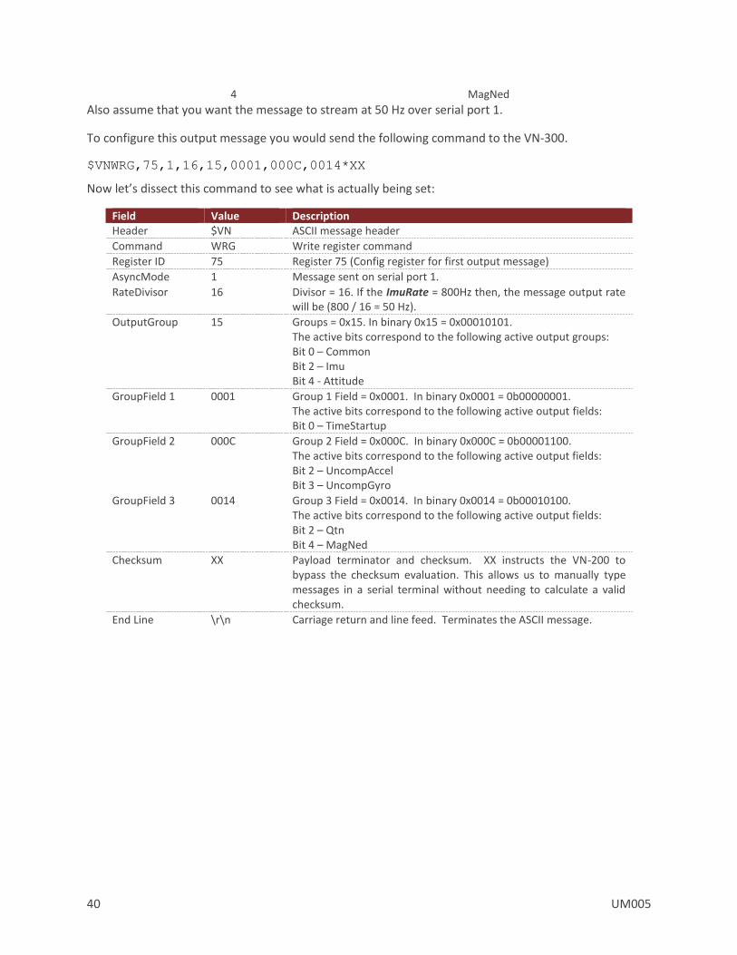
Also assume that you want the message to stream at 50 Hz over serial port 1.
To configure this output message you would send the following command to the VN-300.
$VNWRG,75,1,16,15,0001,000C,0014*XX
Now let’s dissect this command to see what is actually being set:
Field Value Description Header $VN ASCII message header
Command WRG Write register command
Register ID 75 Register 75 (Config register for first output message)
AsyncMode 1 Message sent on serial port 1.
RateDivisor 16 Divisor = 16. If the ImuRate = 800Hz then, the message output rate will be (800 / 16 = 50 Hz).
OutputGroup 15 Groups = 0x15. In binary 0x15 = 0x00010101. The active bits correspond to the following active output groups: Bit 0 – Common Bit 2 – Imu Bit 4 - Attitude
GroupField 1 0001 Group 1 Field = 0x0001. In binary 0x0001 = 0b00000001. The active bits correspond to the following active output fields: Bit 0 – TimeStartup
GroupField 2 000C Group 2 Field = 0x000C. In binary 0x000C = 0b00001100. The active bits correspond to the following active output fields: Bit 2 – UncompAccel Bit 3 – UncompGyro
GroupField 3 0014 Group 3 Field = 0x0014. In binary 0x0014 = 0b00010100. The active bits correspond to the following active output fields: Bit 2 – Qtn Bit 4 – MagNed
Checksum XX Payload terminator and checksum. XX instructs the VN-200 to bypass the checksum evaluation. This allows us to manually type messages in a serial terminal without needing to calculate a valid checksum.
End Line \r\n Carriage return and line feed. Terminates the ASCII message.
UM005 41
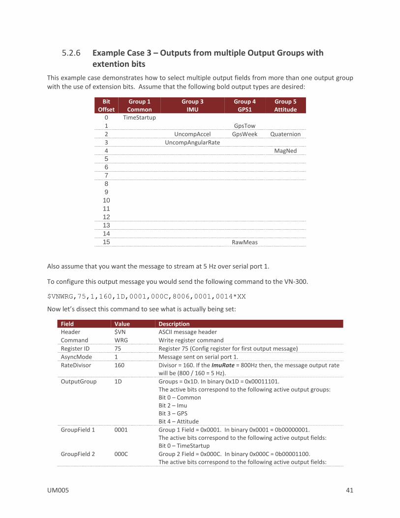
5.2.6 Example Case 3 – Outputs from multiple Output Groups with extention bits
This example case demonstrates how to select multiple output fields from more than one output group with the use of extension bits. Assume that the following bold output types are desired:
Bit Offset
Group 1 Common
Group 3 IMU
Group 4 GPS1
Group 5 Attitude
0 TimeStartup
1 GpsTow
2 UncompAccel GpsWeek Quaternion
3 UncompAngularRate
4 MagNed
5
6
7
8 9
10
11
12
13
14
15 RawMeas
Also assume that you want the message to stream at 5 Hz over serial port 1.
To configure this output message you would send the following command to the VN-300.
$VNWRG,75,1,160,1D,0001,000C,8006,0001,0014*XX
Now let’s dissect this command to see what is actually being set:
Field Value Description Header $VN ASCII message header
Command WRG Write register command
Register ID 75 Register 75 (Config register for first output message)
AsyncMode 1 Message sent on serial port 1.
RateDivisor 160 Divisor = 160. If the ImuRate = 800Hz then, the message output rate will be (800 / 160 = 5 Hz).
OutputGroup 1D Groups = 0x1D. In binary 0x1D = 0x00011101. The active bits correspond to the following active output groups: Bit 0 – Common Bit 2 – Imu Bit 3 – GPS Bit 4 – Attitude
GroupField 1 0001 Group 1 Field = 0x0001. In binary 0x0001 = 0b00000001. The active bits correspond to the following active output fields: Bit 0 – TimeStartup
GroupField 2 000C Group 2 Field = 0x000C. In binary 0x000C = 0b00001100. The active bits correspond to the following active output fields:

42 UM005
Bit 2 – UncompAccel Bit 3 – UncompGyro
GroupField 3 8006,0001 Group 3 Field = 8006,0001. The most significant bit signifies that there subsequent uint16 words involved in this group field. Since the subsequent uint16 word (0001) does not have its extension bit set, the entire group field consist of two uint16 words, and thus can be considered as a uint32 for this example. The remaining fifteen bits in the first word (0006) are the least most significant bits of this uint32 group field. The next word (0001) has its own extension bit which is zero in this case since we do not need to extend out any further. The remaining fifteen bits are the next 15 data bits. The first bit in this group is the 16th overall bit which signals that the RawMeas field has been selected. Bit 1 – GpsTow Bit 2 – GpsWeek Bit 15 – RawMeas
GroupField 4 0014 Group 3 Field = 0x0014. In binary 0x0014 = 0b00010100. The active bits correspond to the following active output fields: Bit 2 – Qtn Bit 4 – MagNed
Checksum XX Payload terminator and checksum. XX instructs the VN-200 to bypass the checksum evaluation. This allows us to manually type messages in a serial terminal without needing to calculate a valid checksum.
End Line \r\n Carriage return and line feed. Terminates the ASCII message.
UM005 43
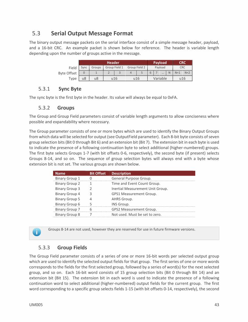
5.3 Serial Output Message Format
The binary output message packets on the serial interface consist of a simple message header, payload, and a 16-bit CRC. An example packet is shown below for reference. The header is variable length depending upon the number of groups active in the message.
Header Payload CRC
Field Sync Groups Group Field 1 Group Field 2 Payload CRC
Byte Offset 0 1 2 3 4 5 6 7 … N N+1 N+2
Type u8 u8 u16 u16 Variable u16
5.3.1 Sync Byte
The sync byte is the first byte in the header. Its value will always be equal to 0xFA.
5.3.2 Groups
The Group and Group Field parameters consist of variable length arguments to allow conciseness where possible and expandability where necessary.
The Group parameter consists of one or more bytes which are used to identify the Binary Output Groups from which data will be selected for output (see OutputField parameter). Each 8-bit byte consists of seven group selection bits (Bit 0 through Bit 6) and an extension bit (Bit 7). The extension bit in each byte is used to indicate the presence of a following continuation byte to select additional (higher-numbered) groups. The first byte selects Groups 1-7 (with bit offsets 0-6, respectively), the second byte (if present) selects Groups 8-14, and so on. The sequence of group selection bytes will always end with a byte whose extension bit is not set. The various groups are shown below.
Name Bit Offset Description Binary Group 1 0 General Purpose Group.
Binary Group 2 1 Time and Event Count Group.
Binary Group 3 2 Inertial Measurement Unit Group.
Binary Group 4 3 GPS1 Measurement Group.
Binary Group 5 4 AHRS Group.
Binary Group 6 5 INS Group.
Binary Group 7 6 GPS2 Measurement Group.
Binary Group 8 7 Not used. Must be set to zero.
Groups 8-14 are not used, however they are reserved for use in future firmware versions.
5.3.3 Group Fields
The Group Field parameter consists of a series of one or more 16-bit words per selected output group which are used to identify the selected output fields for that group. The first series of one or more words corresponds to the fields for the first selected group, followed by a series of word(s) for the next selected group, and so on. Each 16-bit word consists of 15 group selection bits (Bit 0 through Bit 14) and an extension bit (Bit 15). The extension bit in each word is used to indicate the presence of a following continuation word to select additional (higher-numbered) output fields for the current group. The first word corresponding to a specific group selects fields 1-15 (with bit offsets 0-14, respectively), the second

44 UM005
word (if present) selects fields 16-30, and so on. Each sequence of field selection words corresponding to a selected output group ends with a word whose extension bit is not set, and is then followed by a sequence of words for the next selected group (if any).
The group fields represent which output types have been selected in the active binary groups. The number of group fields in the header will depend upon how many groups are active in the message. The number of group fields present in the header will always be equal to the number of active bits in the group byte. When parsing the binary packet you can count the number of active bits present in the group byte, and then you can assume that this number of group fields will be present in the header. For example if only binary group 1 is selected (Group Byte = 0x01), then only one Group field will be present in the header, thus the header will be 4 bytes in length. If both binary group 1 and 3 are active (Group Byte = 0x05), then two Group field elements will be present in the header (4 bytes), thus the header in this case will be 6 bytes in length.
5.3.4 Payload
The payload will consist of the output data selected based upon the bits selected in the group byte and the group field bytes. All output data in the payload section consist of the active outputs selected for binary group 1, followed by the active outputs selected for binary group 2, and so forth. No padding bytes are used between output fields.
5.3.5 CRC
The CRC consists of a 16-bit CRC of the packet. The CRC is calculated over the packet starting just after the sync byte in the header (not including the sync byte) and ending at the end of the payload. More information about the CRC algorithm and example code for how to perform the calculation is shown in the Checksum/CRC section of the Software Architecture chapter. The CRC is selected such that if you compute the 16-bit CRC starting with the group byte and include the CRC itself, a valid packet will result in 0x0000 computed by the running CRC calculation over the entire packet. This provides a simple way of detecting packet corruption by simply checking to see if the CRC calculation of the entire packet (not including the sync byte) results in zero.

UM005 45
5.3.6 Payload Length
When parsing the packet you will need to know the length of the payload (in bytes) in order to know where the packet ends in the data stream. In order to reduce the overhead of the packet header length, the length of the payload is not included in the header. Instead it should be derived based upon determining the type of data present in the packet. All output data types are fixed length, thus the total length of the payload can be determined based upon inspection of the group byte and the group field bytes. In most applications you will likely only use a few binary output types, thus hard coding the payload length in your parser is the easiest approach. If you want to develop a more generic parser that can handle all available data output types supported by the VN-300, the easiest approach is to use a table lookup. Below is a table with the payload size (in bytes) for all available output types.
Binary Output Payload Length In Bytes
Group
1 Group
2 Group
3 Group 4
Group 5
Group 6
Group 7
Field 1 8 8 2 8 2 2 8
Field 2 8 8 12 8 12 24 8
Field 3 8 8 12 2 16 24 2
Field 4 12 2 12 1 36 12 1
Field 5 16 8 4 1 12 12 1
Field 6 12 8 4 24 12 12 24
Field 7 24 8 16 24 12 12 24
Field 8 12 4 12 12 12 12 12
Field 9 12 4 12 12 12 12 12
Field 10 24 1 12 12 12 4 12
Field 11 20 1 12 4 28 4 4
Field 12 28 0 2 4 24 68 4
Field 13 2 0 40 2 0 64 2
Field 14 4 0 0 28 0 0 28
Field 15 8 0 0 2+(N*8) 0 0 2+(N*8)
Field 16 0 0 0 12+(N*28) 0 0 12+(N*28)
The messages highlighted in red in the above table are variable length messages. The size of these messages will be dependent upon the number of packets present. See the description of the fields in the appropriate group section below for more information on how to determine the length of these packets.
The above lookup table can be implemented in C as shown below using a simple 2D array. Assuming you are only using group 1 through 7, with support for 16 fields per group, then this lookup table could be implimented using an 8x16 array of bytes consuming only 128 bytes of memory. With the exception of the SatInfo and RawMeas fields in the GPS group, all other fields have a fixed length. The two variable length fields can be handled seperately with a case statement. For these two fields the lookup table contains the length of the fixed portion of the variable length packet (2 for the SatInfo and 12 for the RawMeas fields).
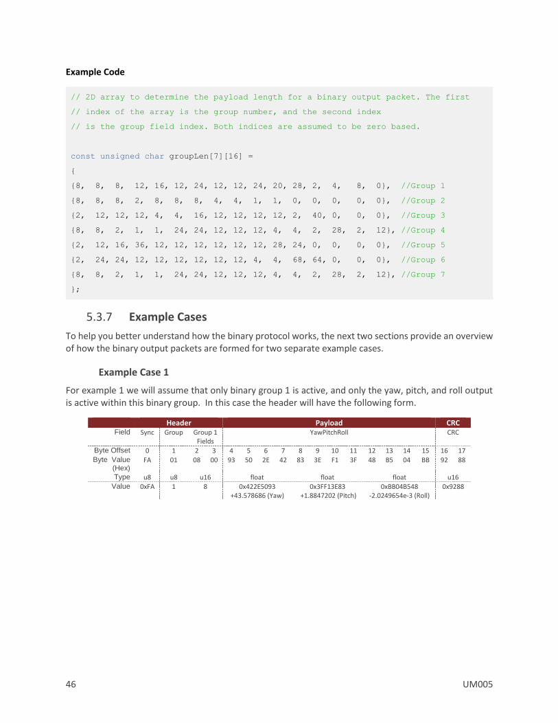
46 UM005
Example Code
// 2D array to determine the payload length for a binary output packet. The first
// index of the array is the group number, and the second index
// is the group field index. Both indices are assumed to be zero based.
const unsigned char groupLen[7][16] =
8, 8, 8, 12, 16, 12, 24, 12, 12, 24, 20, 28, 2, 4, 8, 0, //Group 1
8, 8, 8, 2, 8, 8, 8, 4, 4, 1, 1, 0, 0, 0, 0, 0, //Group 2
2, 12, 12, 12, 4, 4, 16, 12, 12, 12, 12, 2, 40, 0, 0, 0, //Group 3
8, 8, 2, 1, 1, 24, 24, 12, 12, 12, 4, 4, 2, 28, 2, 12, //Group 4
2, 12, 16, 36, 12, 12, 12, 12, 12, 12, 28, 24, 0, 0, 0, 0, //Group 5
2, 24, 24, 12, 12, 12, 12, 12, 12, 4, 4, 68, 64, 0, 0, 0, //Group 6
8, 8, 2, 1, 1, 24, 24, 12, 12, 12, 4, 4, 2, 28, 2, 12, //Group 7
;
5.3.7 Example Cases
To help you better understand how the binary protocol works, the next two sections provide an overview of how the binary output packets are formed for two separate example cases.
Example Case 1
For example 1 we will assume that only binary group 1 is active, and only the yaw, pitch, and roll output is active within this binary group. In this case the header will have the following form.
Header Payload CRC Field Sync Group Group 1
Fields YawPitchRoll CRC
Byte Offset 0 1 2 3 4 5 6 7 8 9 10 11 12 13 14 15 16 17 Byte Value
(Hex) FA 01 08 00 93 50 2E 42 83 3E F1 3F 48 B5 04 BB 92 88
Type u8 u8 u16 float float float u16 Value 0xFA 1 8 0x422E5093
+43.578686 (Yaw) 0x3FF13E83
+1.8847202 (Pitch) 0xBB04B548
-2.0249654e-3 (Roll) 0x9288

UM005 47
Example Case 2
For the second example case we will assume that both binary group 1 and 3 are active. In binary group 1, the Ypr output is selected, and in binary group 3, the Temp output is selected.
Header Field Sync Group Group 1
Fields Group 3
Fields
Byte Offset 0 1 2 3 4 5 Byte Value
(Hex) FA 05 08 00 01 00
Type u8 u8 u16 u16 Value 0xFA 0x05 0x08 0x01
Payload CRC Field YawPitchRoll Temp CRC
Byte Offset 6 7 8 9 10 11 12 13 14 15 16 17 18 19 20 21 22 23
Byte Value (Hex)
A4 15 02 42 4D DF EB 3F F6 1A 36 BE BF 2D A4 41 A8 3A
Type float float float float u16
Value 0x420215A4 +32.521133 (Yaw)
0X3FEBDF4D +1.8427521 (Pitch)
0XBE361AF6 -1.7783722e-1 (Roll)
0X41A42DBF +20.522337 (Temp)
0XA83A
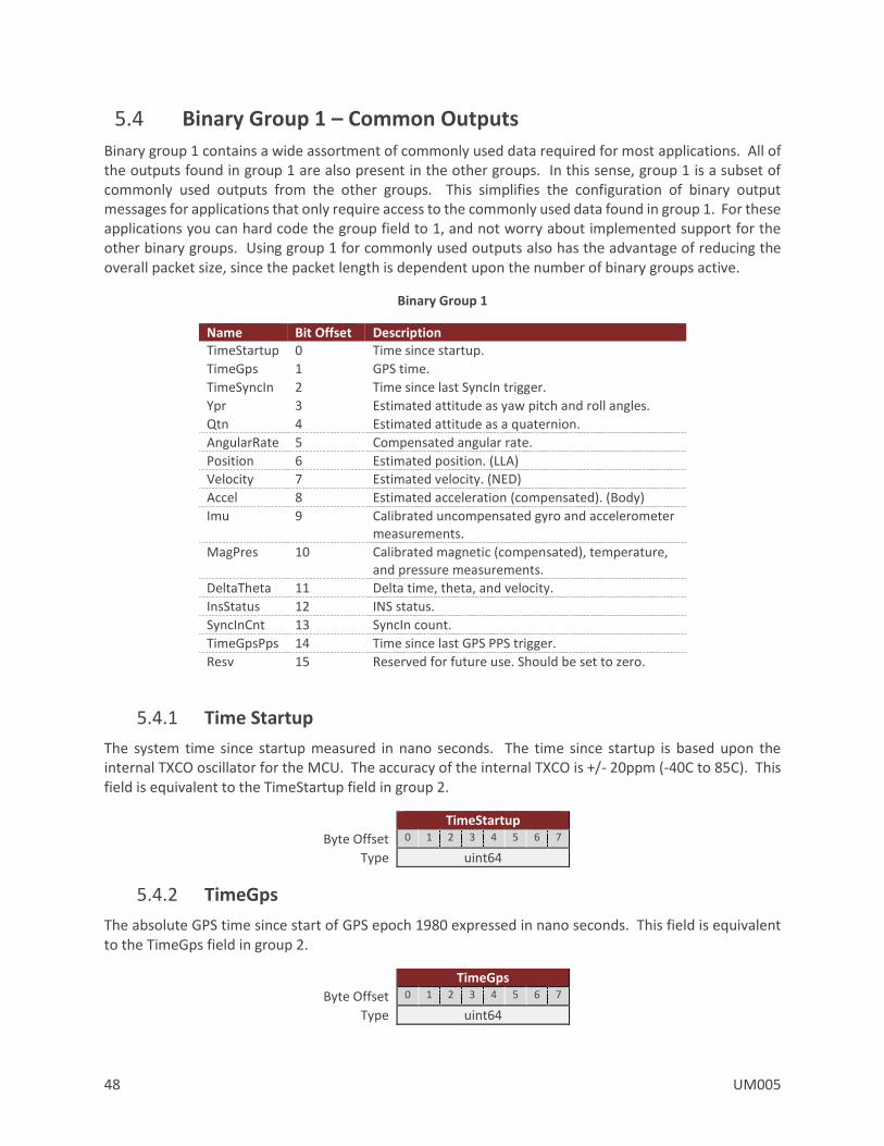
48 UM005
5.4 Binary Group 1 – Common Outputs
Binary group 1 contains a wide assortment of commonly used data required for most applications. All of the outputs found in group 1 are also present in the other groups. In this sense, group 1 is a subset of commonly used outputs from the other groups. This simplifies the configuration of binary output messages for applications that only require access to the commonly used data found in group 1. For these applications you can hard code the group field to 1, and not worry about implemented support for the other binary groups. Using group 1 for commonly used outputs also has the advantage of reducing the overall packet size, since the packet length is dependent upon the number of binary groups active.
Binary Group 1
Name Bit Offset Description TimeStartup 0 Time since startup.
TimeGps 1 GPS time.
TimeSyncIn 2 Time since last SyncIn trigger.
Ypr 3 Estimated attitude as yaw pitch and roll angles.
Qtn 4 Estimated attitude as a quaternion.
AngularRate 5 Compensated angular rate.
Position 6 Estimated position. (LLA)
Velocity 7 Estimated velocity. (NED)
Accel 8 Estimated acceleration (compensated). (Body)
Imu 9 Calibrated uncompensated gyro and accelerometer measurements.
MagPres 10 Calibrated magnetic (compensated), temperature, and pressure measurements.
DeltaTheta 11 Delta time, theta, and velocity.
InsStatus 12 INS status.
SyncInCnt 13 SyncIn count.
TimeGpsPps 14 Time since last GPS PPS trigger.
Resv 15 Reserved for future use. Should be set to zero.
5.4.1 Time Startup
The system time since startup measured in nano seconds. The time since startup is based upon the internal TXCO oscillator for the MCU. The accuracy of the internal TXCO is +/- 20ppm (-40C to 85C). This field is equivalent to the TimeStartup field in group 2.
TimeStartup
Byte Offset 0 1 2 3 4 5 6 7
Type uint64
5.4.2 TimeGps
The absolute GPS time since start of GPS epoch 1980 expressed in nano seconds. This field is equivalent to the TimeGps field in group 2.
TimeGps
Byte Offset 0 1 2 3 4 5 6 7
Type uint64

UM005 49
5.4.3 TimeSyncIn
The time since the last SyncIn trigger event expressed in nano seconds. This field is equivalent to the TimeSyncIn field in group 2.
TimeSyncIn
Byte Offset 0 1 2 3 4 5 6 7
Type uint64
5.4.4 YawPitchRoll
The estimated attitude Yaw, Pitch, and Roll angles measured in degrees. The attitude is given as a 3,2,1 Euler angle sequence describing the body frame with respect to the local North East Down (NED) frame. This field is equivalent to the YawPitchRoll field in group 5.
YawPitchRoll
yaw pitch roll
Byte Offset 0 1 2 3 4 5 6 7 8 9 10 11
Type float float float
5.4.5 Quaternion
The estimated attitude quaternion. The last term is the scalar value. The attitude is given as the body frame with respect to the local North East Down (NED) frame. This field is equivalent to the Quaternion field in group 5.
Quaternion
qtn[0] qtn[1] qtn[2] qtn[3]
Byte Offset 0 1 2 3 4 5 6 7 8 9 10 11 12 13 14 15
Type float float float float
5.4.6 AngularRate
The estimated angular rate measured in rad/s. The angular rates are compensated by the onboard filter bias estimates. The angular rate is expressed in the body frame. This field is equivalent to the AngularRate field in group 3.
AngularRate
rate[0] rate[1] rate[2]
Byte Offset 0 1 2 3 4 5 6 7 8 9 10 11
Type float float float
5.4.7 Position
The estimated position given as latitude, longitude, and altitude given in [deg, deg, m] respectively. This field is equivalent to the PosLla field in group 6.
Position
latitude longitude altitude
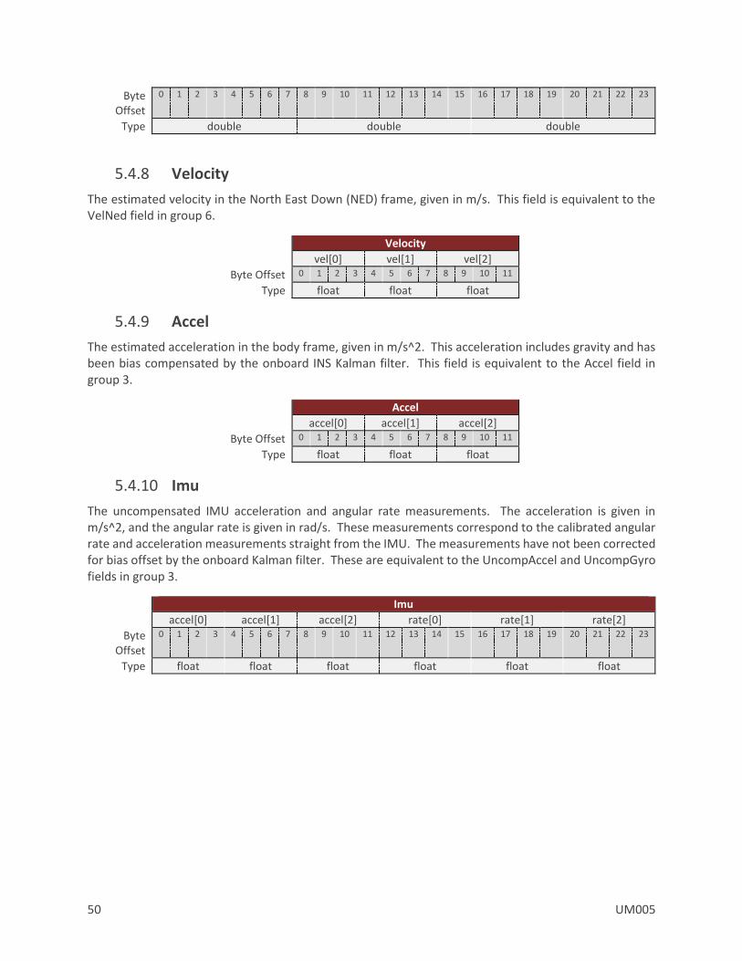
50 UM005
Byte Offset
0 1 2 3 4 5 6 7 8 9 10 11 12 13 14 15 16 17 18 19 20 21 22 23
Type double double double
5.4.8 Velocity
The estimated velocity in the North East Down (NED) frame, given in m/s. This field is equivalent to the VelNed field in group 6.
Velocity
vel[0] vel[1] vel[2]
Byte Offset 0 1 2 3 4 5 6 7 8 9 10 11
Type float float float
5.4.9 Accel
The estimated acceleration in the body frame, given in m/s^2. This acceleration includes gravity and has been bias compensated by the onboard INS Kalman filter. This field is equivalent to the Accel field in group 3.
Accel
accel[0] accel[1] accel[2]
Byte Offset 0 1 2 3 4 5 6 7 8 9 10 11
Type float float float
5.4.10 Imu
The uncompensated IMU acceleration and angular rate measurements. The acceleration is given in m/s^2, and the angular rate is given in rad/s. These measurements correspond to the calibrated angular rate and acceleration measurements straight from the IMU. The measurements have not been corrected for bias offset by the onboard Kalman filter. These are equivalent to the UncompAccel and UncompGyro fields in group 3.
Imu
accel[0] accel[1] accel[2] rate[0] rate[1] rate[2]
Byte Offset
0 1 2 3 4 5 6 7 8 9 10 11 12 13 14 15 16 17 18 19 20 21 22 23
Type float float float float float float
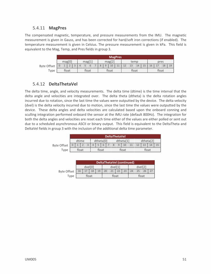
UM005 51
5.4.11 MagPres
The compensated magnetic, temperature, and pressure measurements from the IMU. The magnetic measurement is given in Gauss, and has been corrected for hard/soft iron corrections (if enabled). The temperature measurement is given in Celsius. The pressure measurement is given in kPa. This field is equivalent to the Mag, Temp, and Pres fields in group 3.
MagPres
mag[0] mag[1] mag[2] temp pres
Byte Offset 0 1 2 3 4 5 6 7 8 9 10 11 12 13 14 15 16 17 18 19
Type float float float float float
5.4.12 DeltaThetaVel
The delta time, angle, and velocity measurements. The delta time (dtime) is the time interval that the delta angle and velocities are integrated over. The delta theta (dtheta) is the delta rotation angles incurred due to rotation, since the last time the values were outputted by the device. The delta velocity (dvel) is the delta velocity incurred due to motion, since the last time the values were outputted by the device. These delta angles and delta velocities are calculated based upon the onboard conning and sculling integration performed onboard the sensor at the IMU rate (default 800Hz). The integration for both the delta angles and velocities are reset each time either of the values are either polled or sent out due to a scheduled asynchronous ASCII or binary output. This field is equivalent to the DeltaTheta and DeltaVel fields in group 3 with the inclusion of the additional delta time parameter.
DeltaThetaVel
dtime dtheta[0] dtheta[1] dtheta[2]
Byte Offset 0 1 2 3 4 5 6 7 8 9 10 11 12 13 14 15
Type float float float float
DeltaThetaVel (continued)
dvel[0] dvel[1] dvel[2]
Byte Offset 16 17 18 19 20 21 22 23 24 25 26 27
Type float float float

52 UM005
5.4.13 InsStatus
The INS status bitfield. This field is equivalent to the InsSatus field in group 6. See INS Solution LLA Register for more information on the individual bits in this field.
SolStatus
Byte Offset 0 1
Type u16
5.4.14 SyncInCnt
The number of SyncIn trigger events that have occurred. This field is equivalent to the SyncInCnt field in group 2.
SyncInCnt
Byte Offset 0 1 2 3
Type u32
5.4.15 TimeGpsPps
The time since the last GPS PPS trigger event expressed in nano seconds. This field is equivalent to the TimePPS field in group 2.
TimeGpsPps
Byte Offset 0 1 2 3 4 5 6 7
Type uint64
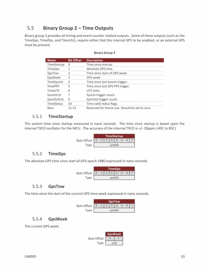
UM005 53
5.5 Binary Group 2 – Time Outputs
Binary group 2 provides all timing and event counter related outputs. Some of these outputs (such as the TimeGps, TimePps, and TimeUtc), require either that the internal GPS to be enabled, or an external GPS must be present.
Binary Group 2
Name Bit Offset Description TimeStartup 0 Time since startup.
TimeGps 1 Absolute GPS time.
GpsTow 2 Time since start of GPS week.
GpsWeek 3 GPS week.
TimeSyncIn 4 Time since last SyncIn trigger.
TimePPS 5 Time since last GPS PPS trigger.
TimeUTC 6 UTC time.
SyncInCnt 7 SyncIn trigger count.
SyncOutCnt 9 SyncOut trigger count.
TimeStatus 10 Time valid status flags.
Resv 11-15 Reserved for future use. Should be set to zero.
5.5.1 TimeStartup
The system time since startup measured in nano seconds. The time since startup is based upon the internal TXCO oscillator for the MCU. The accuracy of the internal TXCO is +/- 20ppm (-40C to 85C).
TimeStartup
Byte Offset 0 1 2 3 4 5 6 7
Type uint64
5.5.2 TimeGps
The absolute GPS time since start of GPS epoch 1980 expressed in nano seconds.
TimeGps
Byte Offset 0 1 2 3 4 5 6 7
Type uint64
5.5.3 GpsTow
The time since the start of the current GPS time week expressed in nano seconds.
GpsTow
Byte Offset 0 1 2 3 4 5 6 7
Type uint64
5.5.4 GpsWeek
The current GPS week.
GpsWeek
Byte Offset 0 1
Type u16

54 UM005
5.5.5 TimeSyncIn
The time since the last SyncIn event trigger expressed in nano seconds.
TimeSyncIn
Byte Offset 0 1 2 3 4 5 6 7
Type uint64
5.5.6 TimeGpsPps
The time since the last GPS PPS trigger event expressed in nano seconds.
TimePps
Byte Offset 0 1 2 3 4 5 6 7
Type uint64
5.5.7 TimeUtc
The current UTC time. The year is given as a signed byte year offset from the year 2000. For example the year 2013 would be given as year 13.
TimeUtc
Fields year month day hour min sec ms
Byte Offset 0 1 2 3 4 5 6 7
Type s8 u8 u8 u8 u8 u8 u16
5.5.8 SyncInCnt
The number of SyncIn trigger events that have occurred.
SyncInCnt
Byte Offset 0 1 2 3
Type u32
5.5.9 SyncOutCnt
The number of SyncOut trigger events that have occurred.
SyncOutCnt
Byte Offset 0 1 2 3
Type u32
5.5.10 TimeStatus
Time valid status flags.
TimeStatus
Byte Offset 0
Type u8
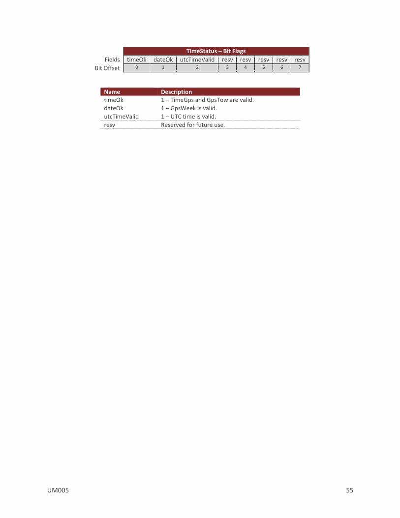
UM005 55
TimeStatus – Bit Flags
Fields timeOk dateOk utcTimeValid resv resv resv resv resv
Bit Offset 0 1 2 3 4 5 6 7
Name Description timeOk 1 – TimeGps and GpsTow are valid.
dateOk 1 – GpsWeek is valid.
utcTimeValid 1 – UTC time is valid.
resv Reserved for future use.
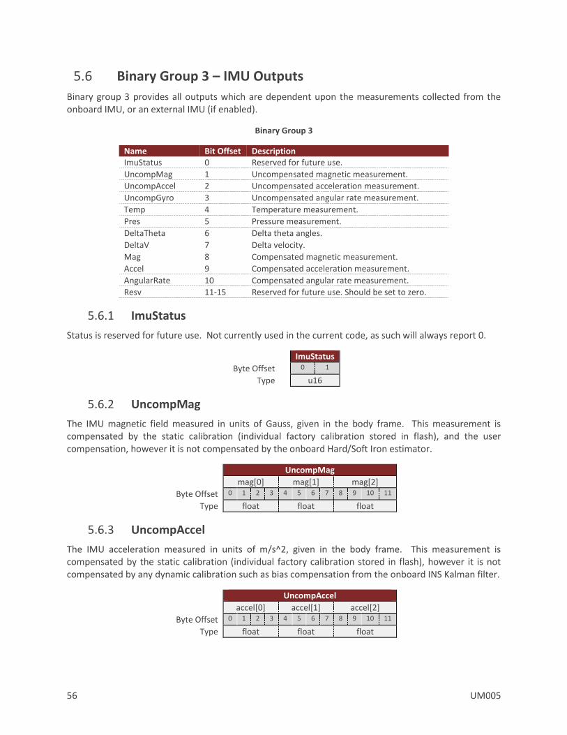
56 UM005
5.6 Binary Group 3 – IMU Outputs
Binary group 3 provides all outputs which are dependent upon the measurements collected from the onboard IMU, or an external IMU (if enabled).
Binary Group 3
Name Bit Offset Description ImuStatus 0 Reserved for future use.
UncompMag 1 Uncompensated magnetic measurement.
UncompAccel 2 Uncompensated acceleration measurement.
UncompGyro 3 Uncompensated angular rate measurement.
Temp 4 Temperature measurement.
Pres 5 Pressure measurement.
DeltaTheta 6 Delta theta angles.
DeltaV 7 Delta velocity.
Mag 8 Compensated magnetic measurement.
Accel 9 Compensated acceleration measurement.
AngularRate 10 Compensated angular rate measurement.
Resv 11-15 Reserved for future use. Should be set to zero.
5.6.1 ImuStatus
Status is reserved for future use. Not currently used in the current code, as such will always report 0.
ImuStatus
Byte Offset 0 1
Type u16
5.6.2 UncompMag
The IMU magnetic field measured in units of Gauss, given in the body frame. This measurement is compensated by the static calibration (individual factory calibration stored in flash), and the user compensation, however it is not compensated by the onboard Hard/Soft Iron estimator.
UncompMag
mag[0] mag[1] mag[2]
Byte Offset 0 1 2 3 4 5 6 7 8 9 10 11
Type float float float
5.6.3 UncompAccel
The IMU acceleration measured in units of m/s^2, given in the body frame. This measurement is compensated by the static calibration (individual factory calibration stored in flash), however it is not compensated by any dynamic calibration such as bias compensation from the onboard INS Kalman filter.
UncompAccel
accel[0] accel[1] accel[2]
Byte Offset 0 1 2 3 4 5 6 7 8 9 10 11
Type float float float
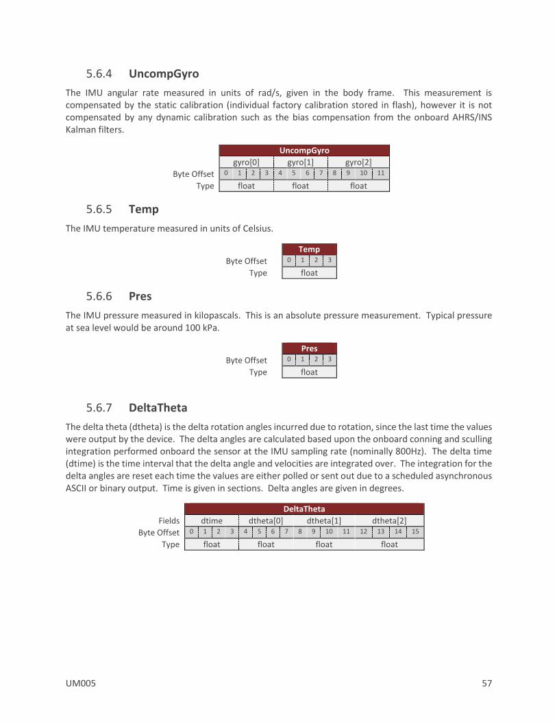
UM005 57
5.6.4 UncompGyro
The IMU angular rate measured in units of rad/s, given in the body frame. This measurement is compensated by the static calibration (individual factory calibration stored in flash), however it is not compensated by any dynamic calibration such as the bias compensation from the onboard AHRS/INS Kalman filters.
UncompGyro
gyro[0] gyro[1] gyro[2]
Byte Offset 0 1 2 3 4 5 6 7 8 9 10 11
Type float float float
5.6.5 Temp
The IMU temperature measured in units of Celsius.
Temp
Byte Offset 0 1 2 3
Type float
5.6.6 Pres
The IMU pressure measured in kilopascals. This is an absolute pressure measurement. Typical pressure at sea level would be around 100 kPa.
Pres
Byte Offset 0 1 2 3
Type float
5.6.7 DeltaTheta
The delta theta (dtheta) is the delta rotation angles incurred due to rotation, since the last time the values were output by the device. The delta angles are calculated based upon the onboard conning and sculling integration performed onboard the sensor at the IMU sampling rate (nominally 800Hz). The delta time (dtime) is the time interval that the delta angle and velocities are integrated over. The integration for the delta angles are reset each time the values are either polled or sent out due to a scheduled asynchronous ASCII or binary output. Time is given in sections. Delta angles are given in degrees.
DeltaTheta
Fields dtime dtheta[0] dtheta[1] dtheta[2]
Byte Offset 0 1 2 3 4 5 6 7 8 9 10 11 12 13 14 15
Type float float float float
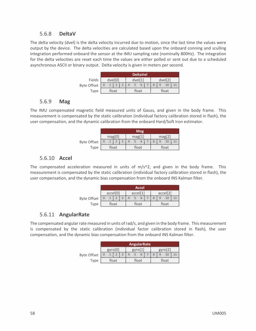
58 UM005
5.6.8 DeltaV
The delta velocity (dvel) is the delta velocity incurred due to motion, since the last time the values were output by the device. The delta velocities are calculated based upon the onboard conning and sculling integration performed onboard the sensor at the IMU sampling rate (nominally 800Hz). The integration for the delta velocities are reset each time the values are either polled or sent out due to a scheduled asynchronous ASCII or binary output. Delta velocity is given in meters per second.
DeltaVel
Fields dvel[0] dvel[1] dvel[2]
Byte Offset 0 1 2 3 4 5 6 7 8 9 10 11
Type float float float
5.6.9 Mag
The IMU compensated magnetic field measured units of Gauss, and given in the body frame. This measurement is compensated by the static calibration (individual factory calibration stored in flash), the user compensation, and the dynamic calibration from the onboard Hard/Soft Iron estimator.
Mag
mag[0] mag[1] mag[2]
Byte Offset 0 1 2 3 4 5 6 7 8 9 10 11
Type float float float
5.6.10 Accel
The compensated acceleration measured in units of m/s^2, and given in the body frame. This measurement is compensated by the static calibration (individual factory calibration stored in flash), the user compensation, and the dynamic bias compensation from the onboard INS Kalman filter.
Accel
accel[0] accel[1] accel[2]
Byte Offset 0 1 2 3 4 5 6 7 8 9 10 11
Type float float float
5.6.11 AngularRate
The compensated angular rate measured in units of rad/s, and given in the body frame. This measurement is compensated by the static calibration (individual factor calibration stored in flash), the user compensation, and the dynamic bias compensation from the onboard INS Kalman filter.
AngularRate
gyro[0] gyro[1] gyro[2]
Byte Offset 0 1 2 3 4 5 6 7 8 9 10 11
Type float float float
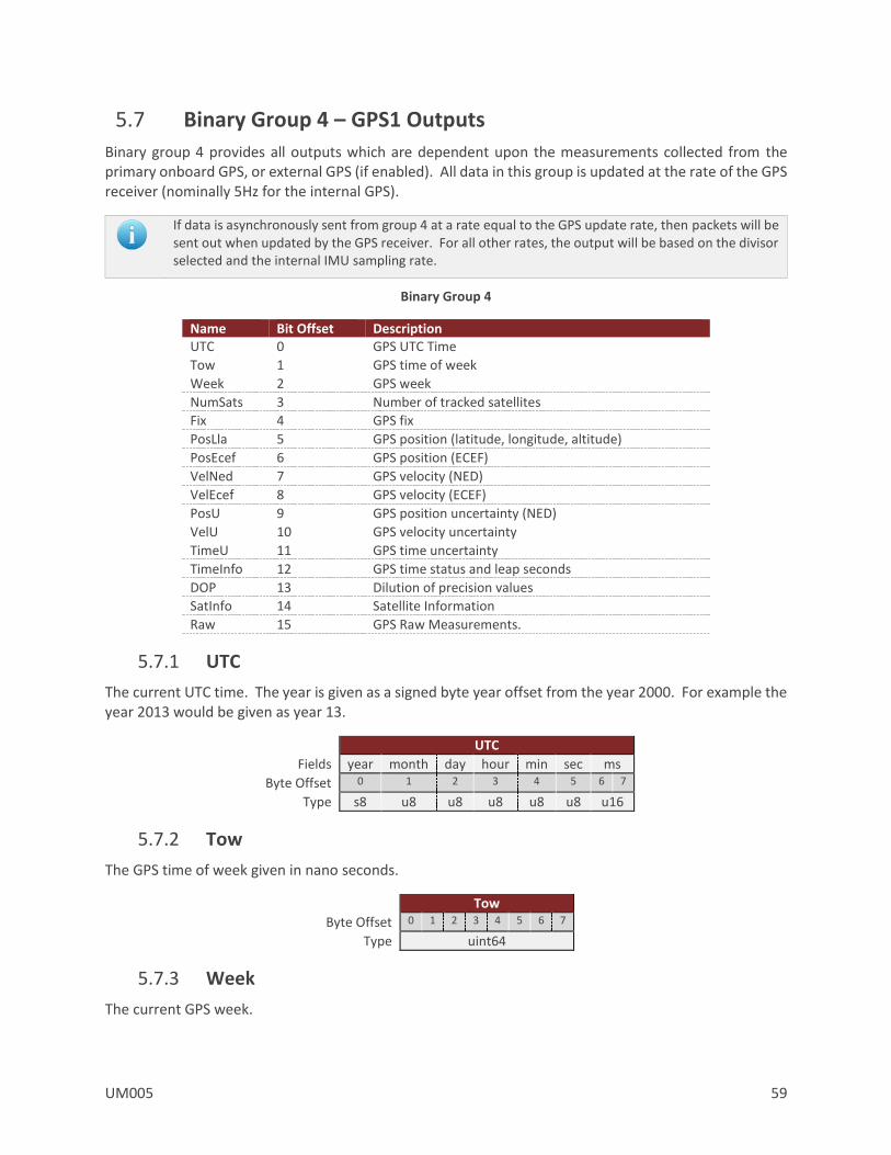
UM005 59
5.7 Binary Group 4 – GPS1 Outputs
Binary group 4 provides all outputs which are dependent upon the measurements collected from the primary onboard GPS, or external GPS (if enabled). All data in this group is updated at the rate of the GPS receiver (nominally 5Hz for the internal GPS).
If data is asynchronously sent from group 4 at a rate equal to the GPS update rate, then packets will be sent out when updated by the GPS receiver. For all other rates, the output will be based on the divisor selected and the internal IMU sampling rate.
Binary Group 4
Name Bit Offset Description UTC 0 GPS UTC Time
Tow 1 GPS time of week
Week 2 GPS week
NumSats 3 Number of tracked satellites
Fix 4 GPS fix
PosLla 5 GPS position (latitude, longitude, altitude)
PosEcef 6 GPS position (ECEF)
VelNed 7 GPS velocity (NED)
VelEcef 8 GPS velocity (ECEF)
PosU 9 GPS position uncertainty (NED)
VelU 10 GPS velocity uncertainty
TimeU 11 GPS time uncertainty
TimeInfo 12 GPS time status and leap seconds
DOP 13 Dilution of precision values
SatInfo 14 Satellite Information
Raw 15 GPS Raw Measurements.
5.7.1 UTC
The current UTC time. The year is given as a signed byte year offset from the year 2000. For example the year 2013 would be given as year 13.
UTC
Fields year month day hour min sec ms
Byte Offset 0 1 2 3 4 5 6 7
Type s8 u8 u8 u8 u8 u8 u16
5.7.2 Tow
The GPS time of week given in nano seconds.
Tow
Byte Offset 0 1 2 3 4 5 6 7
Type uint64
5.7.3 Week
The current GPS week.
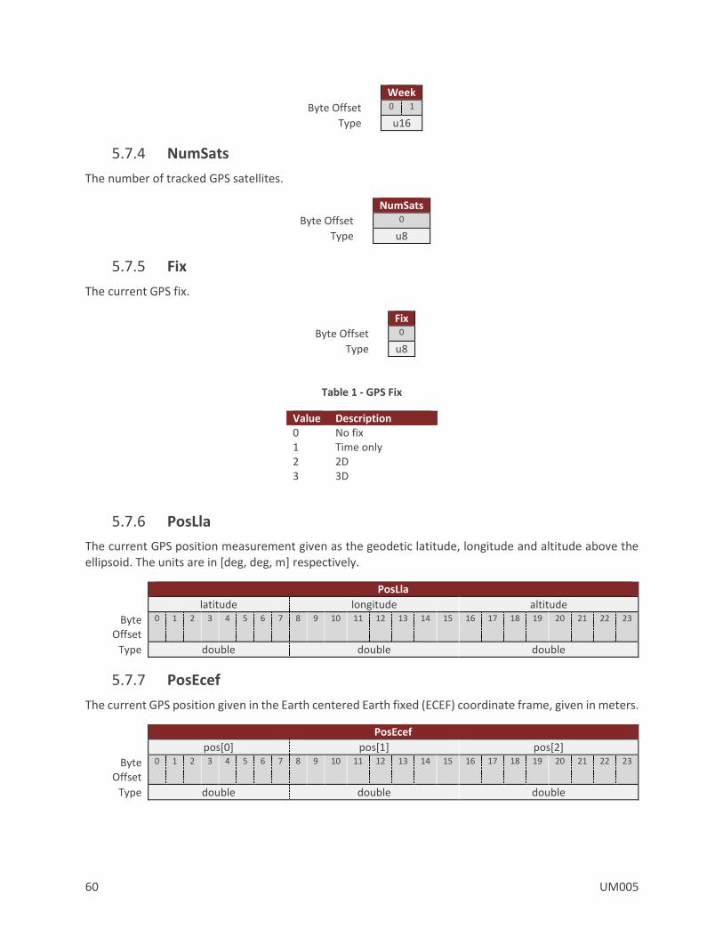
60 UM005
Week
Byte Offset 0 1
Type u16
5.7.4 NumSats
The number of tracked GPS satellites.
NumSats
Byte Offset 0
Type u8
5.7.5 Fix
The current GPS fix.
Fix
Byte Offset 0
Type u8
Table 1 - GPS Fix
Value Description 0 No fix 1 Time only 2 2D 3 3D
5.7.6 PosLla
The current GPS position measurement given as the geodetic latitude, longitude and altitude above the ellipsoid. The units are in [deg, deg, m] respectively.
PosLla
latitude longitude altitude
Byte Offset
0 1 2 3 4 5 6 7 8 9 10 11 12 13 14 15 16 17 18 19 20 21 22 23
Type double double double
5.7.7 PosEcef
The current GPS position given in the Earth centered Earth fixed (ECEF) coordinate frame, given in meters.
PosEcef
pos[0] pos[1] pos[2]
Byte Offset
0 1 2 3 4 5 6 7 8 9 10 11 12 13 14 15 16 17 18 19 20 21 22 23
Type double double double

UM005 61
5.7.8 VelNed
The current GPS velocity in the North East Down (NED) coordinate frame, given in m/s.
VelNed
vel[0] vel[1] vel[2]
Byte Offset 0 1 2 3 4 5 6 7 8 9 10 11
Type float float float
5.7.9 VelEcef
The current GPS velocity in the Earth centered Earth fixed (ECEF) coordinate frame, given in m/s.
VelEcef
vel[0] vel[1] vel[2]
Byte Offset 0 1 2 3 4 5 6 7 8 9 10 11
Type float float float
5.7.10 PosU
The current GPS position uncertainty in the North East Down (NED) coordinate frame, given in meters.
PosU
posU[0] posU[1] posU[2]
Byte Offset 0 1 2 3 4 5 6 7 8 9 10 11
Type float float float
5.7.11 VelU
The current GPS velocity uncertainty, given in m/s.
VelU
Byte Offset 0 1 2 3
Type float
5.7.12 TimeU
The current GPS time uncertainty, given in nano seconds.
TimeU
Byte Offset 0 1 2 3
Type u32
5.7.13 TimeInfo
Flags for valid GPS TOW, week number and UTC and current leap seconds.
TimeInfo
Status LeapSeconds
Byte Offset 0 1
Type u8 s8
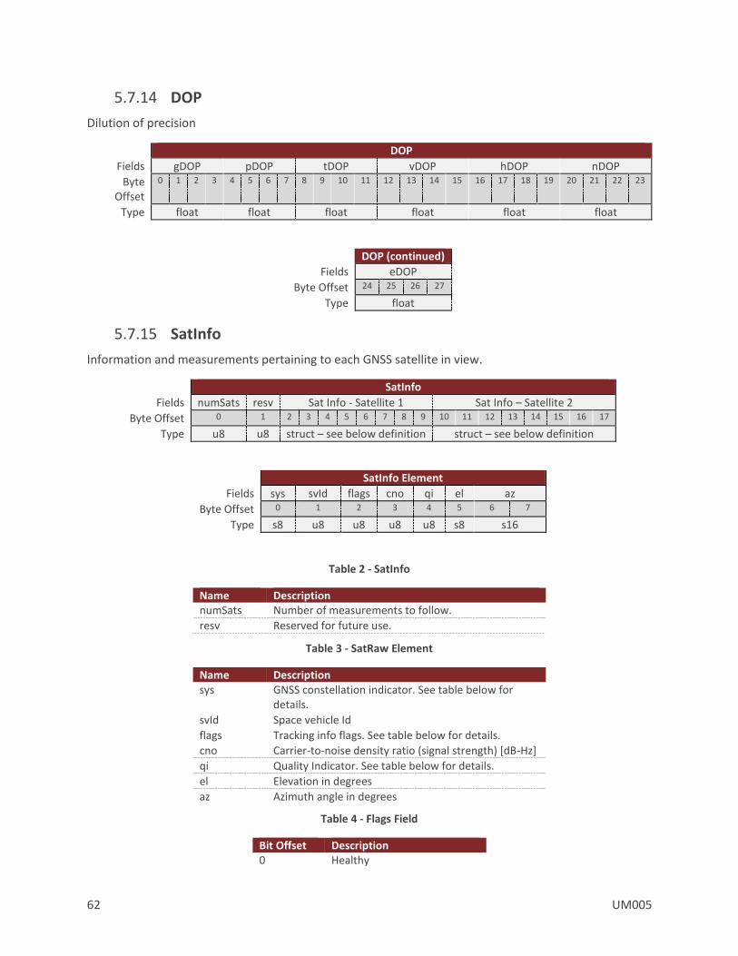
62 UM005
5.7.14 DOP
Dilution of precision
DOP
Fields gDOP pDOP tDOP vDOP hDOP nDOP
Byte Offset
0 1 2 3 4 5 6 7 8 9 10 11 12 13 14 15 16 17 18 19 20 21 22 23
Type float float float float float float
DOP (continued)
Fields eDOP
Byte Offset 24 25 26 27
Type float
5.7.15 SatInfo
Information and measurements pertaining to each GNSS satellite in view.
SatInfo
Fields numSats resv Sat Info - Satellite 1 Sat Info – Satellite 2
Byte Offset 0 1 2 3 4 5 6 7 8 9 10 11 12 13 14 15 16 17
Type u8 u8 struct – see below definition struct – see below definition
SatInfo Element
Fields sys svId flags cno qi el az
Byte Offset 0 1 2 3 4 5 6 7
Type s8 u8 u8 u8 u8 s8 s16
Table 2 - SatInfo
Name Description numSats Number of measurements to follow.
resv Reserved for future use.
Table 3 - SatRaw Element
Name Description sys GNSS constellation indicator. See table below for
details.
svId Space vehicle Id
flags Tracking info flags. See table below for details.
cno Carrier-to-noise density ratio (signal strength) [dB-Hz]
qi Quality Indicator. See table below for details.
el Elevation in degrees
az Azimuth angle in degrees
Table 4 - Flags Field
Bit Offset Description 0 Healthy
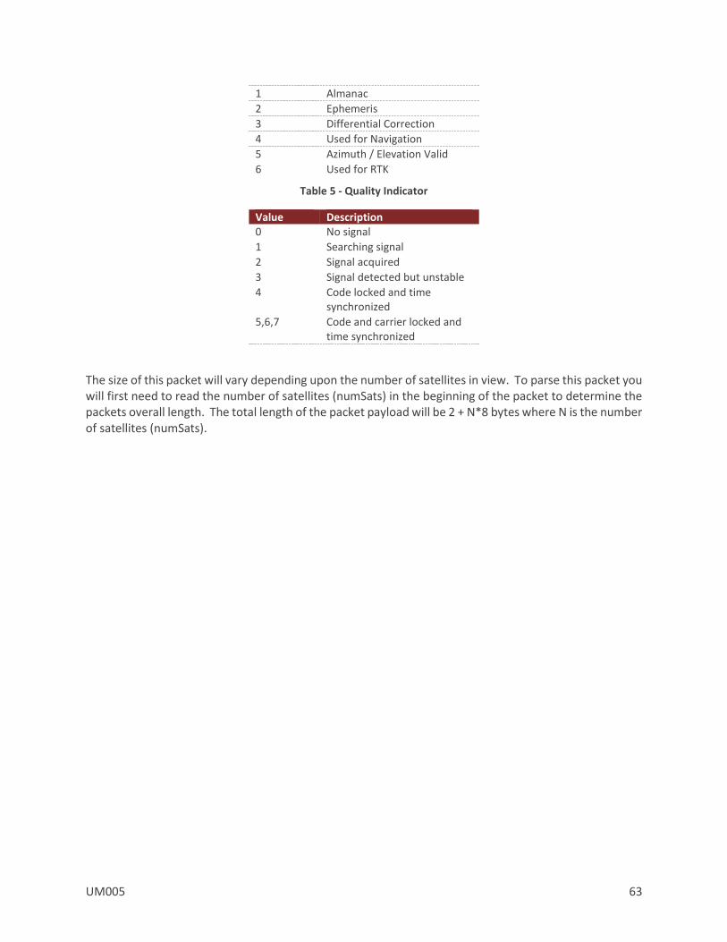
UM005 63
1 Almanac
2 Ephemeris
3 Differential Correction
4 Used for Navigation
5 Azimuth / Elevation Valid
6 Used for RTK
Table 5 - Quality Indicator
Value Description 0 No signal
1 Searching signal
2 Signal acquired
3 Signal detected but unstable
4 Code locked and time synchronized
5,6,7 Code and carrier locked and time synchronized
The size of this packet will vary depending upon the number of satellites in view. To parse this packet you will first need to read the number of satellites (numSats) in the beginning of the packet to determine the packets overall length. The total length of the packet payload will be 2 + N*8 bytes where N is the number of satellites (numSats).

64 UM005
5.7.16 RawMeas
Raw measurements pertaining to each GNSS satellite in view.
RawMeas
Fields tow week numSats resv SatRaw - Satellite 1 SatRaw – Satellite 2
Byte Offset 0-7 8-9 10 11 12-39 40-67
Type double u16 u8 u8 struct – see below definition struct – see below definition
SatRaw Element
Fields sys svId freq chan slot cno flags pr cp dp
Byte Offset
0 1 2 3 4 5 6 7 8-15 16-23 24-27
Type u8 u8 u8 u8 s8 u8 u16 double double float
Table 6 - RawMeas
Name Description tow Time of seek in seconds.
week GPS week number.
numSats Number of measurements to follow.
Table 7 - SatRaw Element
Name Description sys GNSS constellation indicator. See table below for
details.
svId Space vehicle Id.
freq Frequency indicator. See table below for details.
chan Channel Indicator. See table below for details.
slot Slot Id
cno Carrier-to-noise density ratio (signal strength) [dB-Hz]
flags Tracking info flags. See table below for details.
pr Pseudorange measurement in meters.
cp Carrier phase measurement in cycles.
dp Doppler measurement in Hz. Positive sign for approaching satellites.
Table 8 - Sys Field
Value Description 0 GPS
1 SBAS
2 Galileo
3 BeiDou
4 IMES
5 QZSS
6 GLONASS
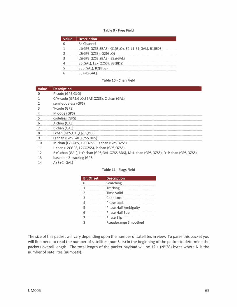
UM005 65
Table 9 - Freq Field
Value Description 0 Rx Channel
1 L1(GPS,QZSS,SBAS), G1(GLO), E2-L1-E1(GAL), B1(BDS)
2 L2(GPS,QZSS), G2(GLO)
3 L5(GPS,QZSS,SBAS), E5a(GAL)
4 E6(GAL), LEX(QZSS), B3(BDS)
5 E5b(GAL), B2(BDS)
6 E5a+b(GAL)
Table 10 - Chan Field
Value Description 0 P-code (GPS,GLO)
1 C/A-code (GPS,GLO,SBAS,QZSS), C chan (GAL)
2 semi-codeless (GPS)
3 Y-code (GPS)
4 M-code (GPS)
5 codeless (GPS)
6 A chan (GAL)
7 B chan (GAL)
8 I chan (GPS,GAL,QZSS,BDS)
9 Q chan (GPS,GAL,QZSS,BDS)
10 M chan (L2CGPS, L2CQZSS), D chan (GPS,QZSS)
11 L chan (L2CGPS, L2CQZSS), P chan (GPS,QZSS)
12 B+C chan (GAL), I+Q chan (GPS,GAL,QZSS,BDS), M+L chan (GPS,QZSS), D+P chan (GPS,QZSS)
13 based on Z-tracking (GPS)
14 A+B+C (GAL)
Table 11 - Flags Field
Bit Offset Description 0 Searching
1 Tracking
2 Time Valid
3 Code Lock
4 Phase Lock
5 Phase Half Ambiguity
6 Phase Half Sub
7 Phase Slip
8 Pseudorange Smoothed
The size of this packet will vary depending upon the number of satellites in view. To parse this packet you will first need to read the number of satellites (numSats) in the beginning of the packet to determine the packets overall length. The total length of the packet payload will be 12 + (N*28) bytes where N is the number of satellites (numSats).

66 UM005
5.8 Binary Group 5 – Attitude Outputs
Binary group 5 provides all estimated outputs which are dependent upon the estimated attitude solution. The attitude will be derived from either the AHRS or the INS, depending upon which filter is currently active and tracking. All of the fields in this group will only be valid if the AHRS/INS filter is currently enabled and tracking.
Binary Group 5
Name Bit Offset Description Reserved 0 Reserved. Not used on this product.
Ypr 1 Yaw Pitch Roll
Qtn 2 Quaternion
DCM 3 Directional Cosine Matrix
MagNed 4 Compensated magnetic (NED)
AccelNed 5 Compensated acceleration (NED)
LinearAccelBody 6 Compensated linear acceleration (no gravity)
LinearAccelNed 7 Compensated linear acceleration (no gravity) (NED)
YprU 8 Yaw Pitch Roll uncertainty
Resv 9-15 Reserved for future use. Should be set to zero.
5.8.1 YawPitchRoll
The estimated attitude Yaw, Pitch, and Roll angles measured in degrees. The attitude is given as a 3,2,1 Euler angle sequence describing the body frame with respect to the local North East Down (NED) frame.
YawPitchRoll
yaw pitch roll
Byte Offset 0 1 2 3 4 5 6 7 8 9 10 11
Type float float float
5.8.2 Quaternion
The estimated attitude quaternion. The last term is the scalar value. The attitude is given as the body frame with respect to the local North East Down (NED) frame.
Quaternion
qtn[0] qtn[1] qtn[2] qtn[3]
Byte Offset 0 1 2 3 4 5 6 7 8 9 10 11 12 13 14 15
Type float float float float
5.8.3 DCM
The estimated attitude directional cosine matrix given in column major order. The DCM maps vectors from the North East Down (NED) frame into the body frame.
Dcm
Fields dcm[0] dcm[1] dcm[2] dcm[3] dcm[4] dcm[5]
Byte Offset
0 1 2 3 4 5 6 7 8 9 10 11 12 13 14 15 16 17 18 19 20 21 22 23
Type float float float float float float
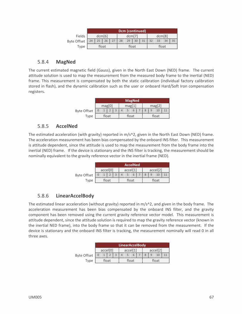
UM005 67
Dcm (continued)
Fields dcm[6] dcm[7] dcm[8]
Byte Offset 24 25 26 27 28 29 30 31 32 33 34 35
Type float float float
5.8.4 MagNed
The current estimated magnetic field (Gauss), given in the North East Down (NED) frame. The current attitude solution is used to map the measurement from the measured body frame to the inertial (NED) frame. This measurement is compensated by both the static calibration (individual factory calibration stored in flash), and the dynamic calibration such as the user or onboard Hard/Soft Iron compensation registers.
MagNed
mag[0] mag[1] mag[2]
Byte Offset 0 1 2 3 4 5 6 7 8 9 10 11
Type float float float
5.8.5 AccelNed
The estimated acceleration (with gravity) reported in m/s^2, given in the North East Down (NED) frame. The acceleration measurement has been bias compensated by the onboard INS filter. This measurement is attitude dependent, since the attitude is used to map the measurement from the body frame into the inertial (NED) frame. If the device is stationary and the INS filter is tracking, the measurement should be nominally equivalent to the gravity reference vector in the inertial frame (NED).
AccelNed
accel[0] accel[1] accel[2]
Byte Offset 0 1 2 3 4 5 6 7 8 9 10 11
Type float float float
5.8.6 LinearAccelBody
The estimated linear acceleration (without gravity) reported in m/s^2, and given in the body frame. The acceleration measurement has been bias compensated by the onboard INS filter, and the gravity component has been removed using the current gravity reference vector model. This measurement is attitude dependent, since the attitude solution is required to map the gravity reference vector (known in the inertial NED frame), into the body frame so that it can be removed from the measurement. If the device is stationary and the onboard INS filter is tracking, the measurement nominally will read 0 in all three axes.
LinearAccelBody
accel[0] accel[1] accel[2]
Byte Offset 0 1 2 3 4 5 6 7 8 9 10 11
Type float float float

68 UM005
5.8.7 LinearAccelNed
The estimated linear acceleration (without gravity) reported in m/s^2, and given in the North East Down (NED) frame. This measurement is attitude dependent as the attitude solution is used to map the measurement from the body frame into the inertial (NED) frame. This acceleration measurement has been bias compensated by the onboard INS filter, and the gravity component has been removed using the current gravity reference vector estimate. If the device is stationary and the onboard INS filter is tracking, the measurement nominally will read 0 in all three axes.
LinearAccelNed
accel[0] accel[1] accel[2]
Byte Offset 0 1 2 3 4 5 6 7 8 9 10 11
Type float float float
5.8.8 YprU
The estimated attitude (Yaw, Pitch, Roll) uncertainty (1 Sigma), reported in degrees.
YprU
yaw pitch roll
Byte Offset 0 1 2 3 4 5 6 7 8 9 10 11
Type float float float
The estimated attitude (YprU) field is not valid when the INS Scenario mode in the INS Basic Configuration register is set to AHRS mode. See the INS Basic Configuration Register in the INS section for more details.
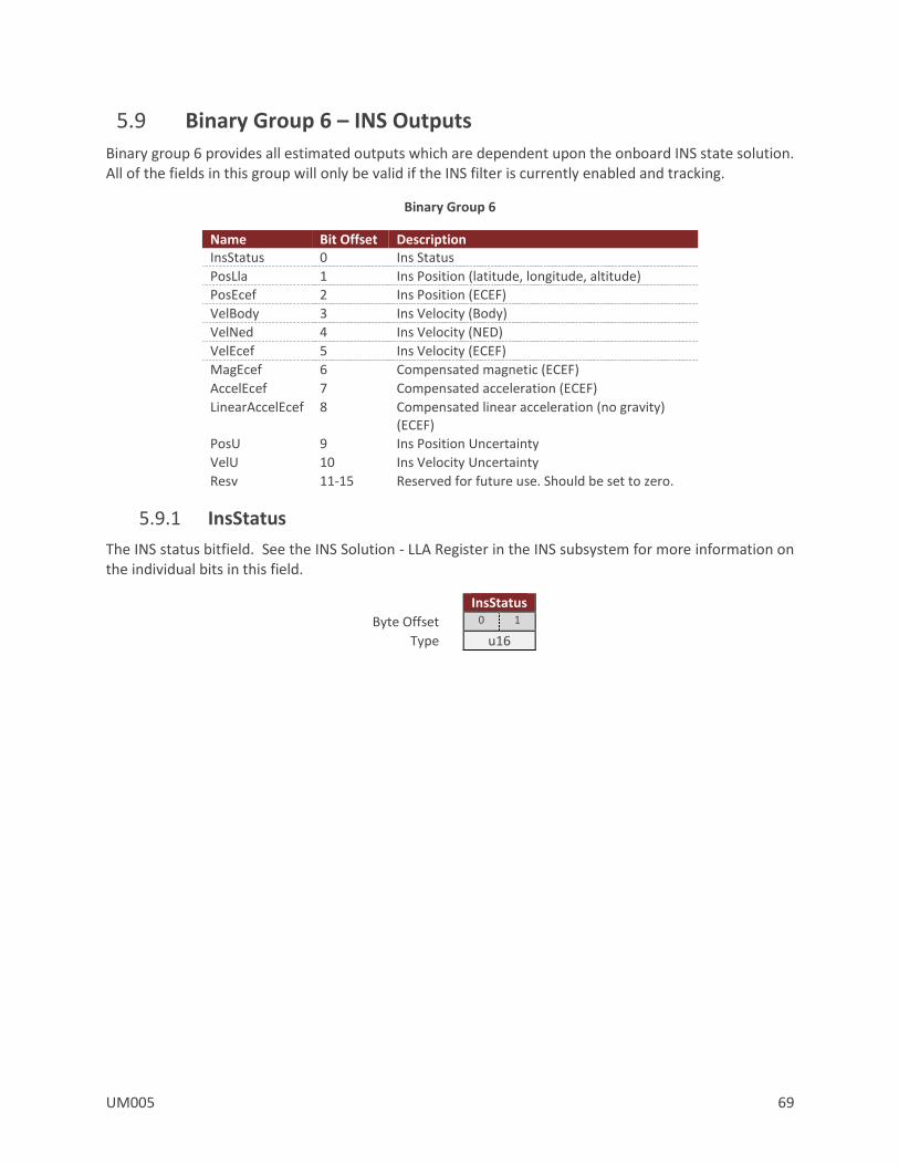
UM005 69
5.9 Binary Group 6 – INS Outputs
Binary group 6 provides all estimated outputs which are dependent upon the onboard INS state solution. All of the fields in this group will only be valid if the INS filter is currently enabled and tracking.
Binary Group 6
Name Bit Offset Description InsStatus 0 Ins Status
PosLla 1 Ins Position (latitude, longitude, altitude)
PosEcef 2 Ins Position (ECEF)
VelBody 3 Ins Velocity (Body)
VelNed 4 Ins Velocity (NED)
VelEcef 5 Ins Velocity (ECEF)
MagEcef 6 Compensated magnetic (ECEF)
AccelEcef 7 Compensated acceleration (ECEF)
LinearAccelEcef 8 Compensated linear acceleration (no gravity) (ECEF)
PosU 9 Ins Position Uncertainty
VelU 10 Ins Velocity Uncertainty
Resv 11-15 Reserved for future use. Should be set to zero.
5.9.1 InsStatus
The INS status bitfield. See the INS Solution - LLA Register in the INS subsystem for more information on the individual bits in this field.
InsStatus
Byte Offset 0 1
Type u16
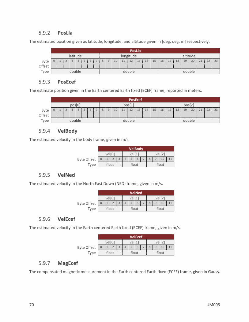
70 UM005
5.9.2 PosLla
The estimated position given as latitude, longitude, and altitude given in [deg, deg, m] respectively.
PosLla
latitude longitude altitude
Byte Offset
0 1 2 3 4 5 6 7 8 9 10 11 12 13 14 15 16 17 18 19 20 21 22 23
Type double double double
5.9.3 PosEcef
The estimate position given in the Earth centered Earth fixed (ECEF) frame, reported in meters.
PosEcef
pos[0] pos[1] pos[2]
Byte Offset
0 1 2 3 4 5 6 7 8 9 10 11 12 13 14 15 16 17 18 19 20 21 22 23
Type double double double
5.9.4 VelBody
The estimated velocity in the body frame, given in m/s.
VelBody
vel[0] vel[1] vel[2]
Byte Offset 0 1 2 3 4 5 6 7 8 9 10 11
Type float float float
5.9.5 VelNed
The estimated velocity in the North East Down (NED) frame, given in m/s.
VelNed
vel[0] vel[1] vel[2]
Byte Offset 0 1 2 3 4 5 6 7 8 9 10 11
Type float float float
5.9.6 VelEcef
The estimated velocity in the Earth centered Earth fixed (ECEF) frame, given in m/s.
VelEcef
vel[0] vel[1] vel[2]
Byte Offset 0 1 2 3 4 5 6 7 8 9 10 11
Type float float float
5.9.7 MagEcef
The compensated magnetic measurement in the Earth centered Earth fixed (ECEF) frame, given in Gauss.

UM005 71
MagEcef
mag[0] mag[1] mag[2]
Byte Offset 0 1 2 3 4 5 6 7 8 9 10 11
Type float float float
5.9.8 AccelEcef
The estimated acceleration (with gravity) reported in m/s^2, given in the Earth centered Earth fixed (ECEF) frame. The acceleration measurement has been bias compensated by the onboard INS filter. This measurement is attitude dependent, since the attitude is used to map the measurement from the body frame into the inertial (ECEF) frame. If the device is stationary and the INS filter is tracking, the measurement should be nominally equivalent to the gravity reference vector in the inertial frame (ECEF).
AccelEcef
accel[0] accel[1] accel[2]
Byte Offset 0 1 2 3 4 5 6 7 8 9 10 11
Type float float float
5.9.9 LinearAccelEcef
The estimated linear acceleration (without gravity) reported in m/s^2, and given in the Earth centered Earth fixed (ECEF) frame. This measurement is attitude dependent as the attitude solution is used to map the measurement from the body frame into the inertial (ECEF) frame. This acceleration measurement has been bias compensated by the onboard INS filter, and the gravity component has been removed using the current gravity reference vector estimate. If the device is stationary and the onboard INS filter is tracking, the measurement will nominally read 0 in all three axes.
LinearAccelEcef
accel[0] accel[1] accel[2]
Byte Offset 0 1 2 3 4 5 6 7 8 9 10 11
Type float float float
5.9.10 PosU
The estimated uncertainty (1 Sigma) in the current position estimate, given in meters.
PosU
Byte Offset 0 1 2 3
Type float
5.9.11 VelU
The estimated uncertainty (1 Sigma) in the current velocity estimate, given in m/s.
VelU
Byte Offset 0 1 2 3
Type float

72 UM005
5.10 Binary Group 7 – GPS2 Outputs
Binary group 7 provides all outputs which are dependent upon the measurements collected from the secondary onboard GPS, or external GPS (if enabled). All data in this group is updated at the rate of the GPS receiver (nominally 5Hz for the internal GPS).
If data is asynchronously sent from group 7 at a rate equal to the GPS update rate, then packets will be sent out when updated by the GPS receiver. For all other rates, the output will be based on the divisor selected and the internal IMU sampling rate.
Binary Group 7
Name Bit Offset Description UTC 0 GPS UTC Time
Tow 1 GPS time of week
Week 2 GPS week
NumSats 3 Number of tracked satellites
Fix 4 GPS fix
PosLla 5 GPS position (latitude, longitude, altitude)
PosEcef 6 GPS position (ECEF)
VelNed 7 GPS velocity (NED)
VelEcef 8 GPS velocity (ECEF)
PosU 9 GPS position uncertainty (NED)
VelU 10 GPS velocity uncertainty
TimeU 11 GPS time uncertainty
TimeInfo 12 GPS time status and leap seconds
DOP 13 Dilution of precision values
SatInfo 14 Satellite Information
Raw 15 GPS Raw Measurements.
5.10.1 UTC
The current UTC time. The year is given as a signed byte year offset from the year 2000. For example the year 2013 would be given as year 13.
UTC
Fields year month day hour min sec ms
Byte Offset 0 1 2 3 4 5 6 7
Type s8 u8 u8 u8 u8 u8 u16
5.10.2 Tow
The GPS time of week given in nano seconds.
Tow
Byte Offset 0 1 2 3 4 5 6 7
Type uint64
5.10.3 Week
The current GPS week.

UM005 73
Week
Byte Offset 0 1
Type u16
5.10.4 NumSats
The number of tracked GPS satellites.
NumSats
Byte Offset 0
Type u8
5.10.5 Fix
The current GPS fix.
Fix
Byte Offset 0
Type u8
Table 12 - GPS Fix
Value Description 0 No fix 1 Time only 2 2D 3 3D
5.10.6 PosLla
The current GPS position measurement given as the geodetic latitude, longitude and altitude above the ellipsoid. The units are in [deg, deg, m] respectively.
PosLla
latitude longitude altitude
Byte Offset
0 1 2 3 4 5 6 7 8 9 10 11 12 13 14 15 16 17 18 19 20 21 22 23
Type double double double
5.10.7 PosEcef
The current GPS position given in the Earth centered Earth fixed (ECEF) coordinate frame, given in meters.
PosEcef
pos[0] pos[1] pos[2]
Byte Offset
0 1 2 3 4 5 6 7 8 9 10 11 12 13 14 15 16 17 18 19 20 21 22 23
Type double double double
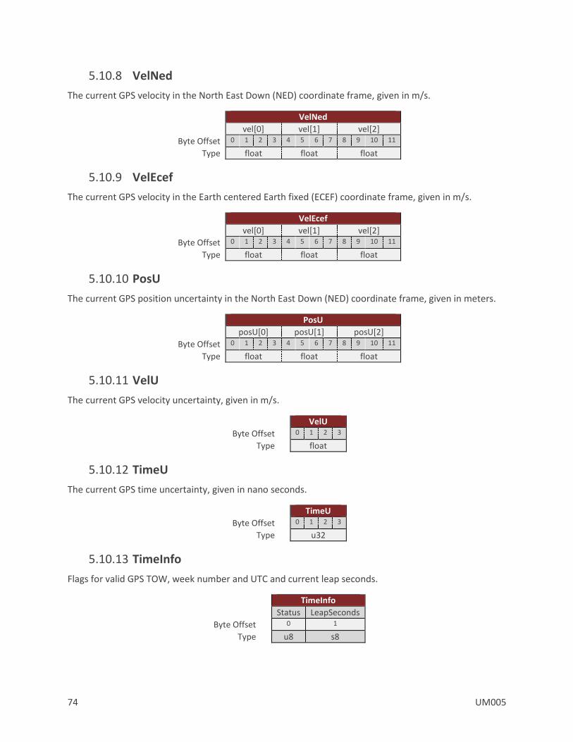
74 UM005
5.10.8 VelNed
The current GPS velocity in the North East Down (NED) coordinate frame, given in m/s.
VelNed
vel[0] vel[1] vel[2]
Byte Offset 0 1 2 3 4 5 6 7 8 9 10 11
Type float float float
5.10.9 VelEcef
The current GPS velocity in the Earth centered Earth fixed (ECEF) coordinate frame, given in m/s.
VelEcef
vel[0] vel[1] vel[2]
Byte Offset 0 1 2 3 4 5 6 7 8 9 10 11
Type float float float
5.10.10 PosU
The current GPS position uncertainty in the North East Down (NED) coordinate frame, given in meters.
PosU
posU[0] posU[1] posU[2]
Byte Offset 0 1 2 3 4 5 6 7 8 9 10 11
Type float float float
5.10.11 VelU
The current GPS velocity uncertainty, given in m/s.
VelU
Byte Offset 0 1 2 3
Type float
5.10.12 TimeU
The current GPS time uncertainty, given in nano seconds.
TimeU
Byte Offset 0 1 2 3
Type u32
5.10.13 TimeInfo
Flags for valid GPS TOW, week number and UTC and current leap seconds.
TimeInfo
Status LeapSeconds
Byte Offset 0 1
Type u8 s8
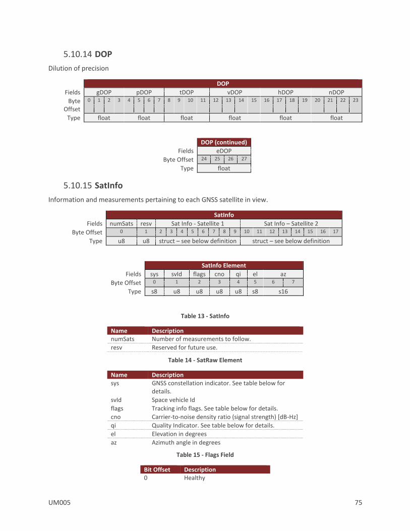
UM005 75
5.10.14 DOP
Dilution of precision
DOP
Fields gDOP pDOP tDOP vDOP hDOP nDOP
Byte Offset
0 1 2 3 4 5 6 7 8 9 10 11 12 13 14 15 16 17 18 19 20 21 22 23
Type float float float float float float
DOP (continued)
Fields eDOP
Byte Offset 24 25 26 27
Type float
5.10.15 SatInfo
Information and measurements pertaining to each GNSS satellite in view.
SatInfo
Fields numSats resv Sat Info - Satellite 1 Sat Info – Satellite 2
Byte Offset 0 1 2 3 4 5 6 7 8 9 10 11 12 13 14 15 16 17
Type u8 u8 struct – see below definition struct – see below definition
SatInfo Element
Fields sys svId flags cno qi el az
Byte Offset 0 1 2 3 4 5 6 7
Type s8 u8 u8 u8 u8 s8 s16
Table 13 - SatInfo
Name Description numSats Number of measurements to follow.
resv Reserved for future use.
Table 14 - SatRaw Element
Name Description sys GNSS constellation indicator. See table below for
details.
svId Space vehicle Id
flags Tracking info flags. See table below for details.
cno Carrier-to-noise density ratio (signal strength) [dB-Hz]
qi Quality Indicator. See table below for details.
el Elevation in degrees
az Azimuth angle in degrees
Table 15 - Flags Field
Bit Offset Description 0 Healthy

76 UM005
1 Almanac
2 Ephemeris
3 Differential Correction
4 Used for Navigation
5 Azimuth / Elevation Valid
6 Used for RTK
Table 16 - Quality Indicator
Value Description 0 No signal
1 Searching signal
2 Signal acquired
3 Signal detected but unstable
4 Code locked and time synchronized
5,6,7 Code and carrier locked and time synchronized
The size of this packet will vary depending upon the number of satellites in view. To parse this packet you will first need to read the number of satellites (numSats) in the beginning of the packet to determine the packets overall length. The total length of the packet payload will be 2 + N*8 bytes where N is the number of satellites (numSats).
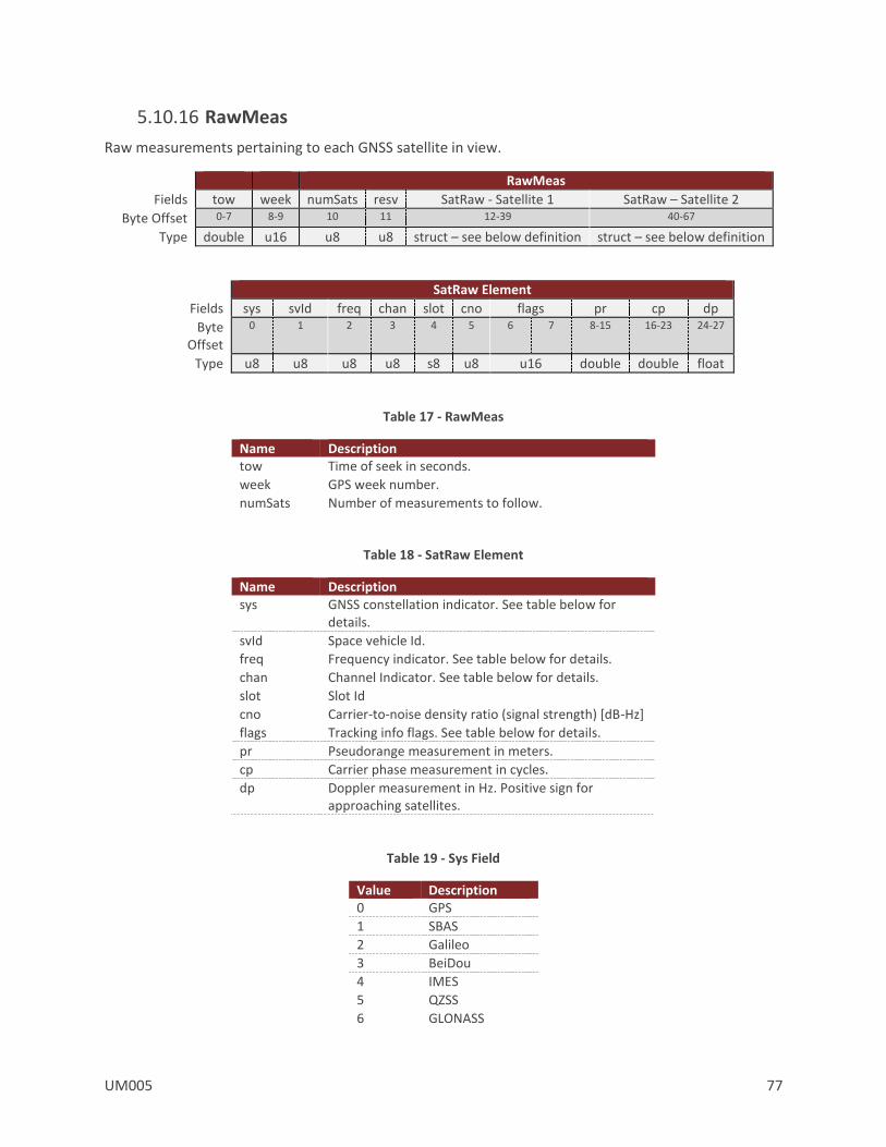
UM005 77
5.10.16 RawMeas
Raw measurements pertaining to each GNSS satellite in view.
RawMeas
Fields tow week numSats resv SatRaw - Satellite 1 SatRaw – Satellite 2
Byte Offset 0-7 8-9 10 11 12-39 40-67
Type double u16 u8 u8 struct – see below definition struct – see below definition
SatRaw Element
Fields sys svId freq chan slot cno flags pr cp dp
Byte Offset
0 1 2 3 4 5 6 7 8-15 16-23 24-27
Type u8 u8 u8 u8 s8 u8 u16 double double float
Table 17 - RawMeas
Name Description tow Time of seek in seconds.
week GPS week number.
numSats Number of measurements to follow.
Table 18 - SatRaw Element
Name Description sys GNSS constellation indicator. See table below for
details.
svId Space vehicle Id.
freq Frequency indicator. See table below for details.
chan Channel Indicator. See table below for details.
slot Slot Id
cno Carrier-to-noise density ratio (signal strength) [dB-Hz]
flags Tracking info flags. See table below for details.
pr Pseudorange measurement in meters.
cp Carrier phase measurement in cycles.
dp Doppler measurement in Hz. Positive sign for approaching satellites.
Table 19 - Sys Field
Value Description 0 GPS
1 SBAS
2 Galileo
3 BeiDou
4 IMES
5 QZSS
6 GLONASS

78 UM005
Table 20 - Freq Field
Value Description 0 Rx Channel
1 L1(GPS,QZSS,SBAS), G1(GLO), E2-L1-E1(GAL), B1(BDS)
2 L2(GPS,QZSS), G2(GLO)
3 L5(GPS,QZSS,SBAS), E5a(GAL)
4 E6(GAL), LEX(QZSS), B3(BDS)
5 E5b(GAL), B2(BDS)
6 E5a+b(GAL)
Table 21 - Chan Field
Value Description 0 P-code (GPS,GLO)
1 C/A-code (GPS,GLO,SBAS,QZSS), C chan (GAL)
2 semi-codeless (GPS)
3 Y-code (GPS)
4 M-code (GPS)
5 codeless (GPS)
6 A chan (GAL)
7 B chan (GAL)
8 I chan (GPS,GAL,QZSS,BDS)
9 Q chan (GPS,GAL,QZSS,BDS)
10 M chan (L2CGPS, L2CQZSS), D chan (GPS,QZSS)
11 L chan (L2CGPS, L2CQZSS), P chan (GPS,QZSS)
12 B+C chan (GAL), I+Q chan (GPS,GAL,QZSS,BDS), M+L chan (GPS,QZSS), D+P chan (GPS,QZSS)
13 based on Z-tracking (GPS)
14 A+B+C (GAL)
Table 22 - Flags Field
Bit Offset Description 0 Searching
1 Tracking
2 Time Valid
3 Code Lock
4 Phase Lock
5 Phase Half Ambiguity
6 Phase Half Sub
7 Phase Slip
8 Pseudorange Smoothed
The size of this packet will vary depending upon the number of satellites in view. To parse this packet you will first need to read the number of satellites (numSats) in the beginning of the packet to determine the packets overall length. The total length of the packet payload will be 12 + (N*28) bytes where N is the number of satellites (numSats).

UM005 79
6 System Module
6.1 Commands
6.1.1 Read Register Command
This command allows the user to read any of the registers on the VN-300. The only required parameter is the ID of the register to be read. The first parameter of the response will contain the same register ID followed by a variable number of parameters. The number of parameters and their formatting is specific to the requested register. Refer to the appropriate register listed in the subsystem sections for details on this formatting. If an invalid register is requested, an error code will be returned.
Example Read Register Command
Example Command Message UART Command $VNRRG,5*46
UART Response $VNRRG,5,9600*65
6.1.2 Write Register Command
This command is used to write data values to a specified register on the VN-300 module. The ID of the register to be written to is the first parameter. This is followed by the data values specific to that register. Refer to the appropriate register listed in the subsystem sections for details on this formatting. If an invalid register is requested, an error code will be returned.
Example Write Register Command
Example Command Message UART Command $VNWRG,5,9600*60
UART Response $VNWRG,5,9600*60

80 UM005
6.1.3 Write Settings Command
This command will write the current register settings into non-volatile memory. Once the settings are stored in non-volatile (Flash) memory, the VN-300 module can be power cycled or reset, and the register will be reloaded from non-volatile memory.
Example Write Settings Command
Example Command Message UART Command $VNWNV*57
UART Response $VNWNV*57
Due to limitations in the flash write speed the write settings command takes ~ 500ms to complete. Any commands that are sent to the sensor during this time will be responded to after the operation is complete.
The sensor must be stationary when issuing a Write Settings Command otherwise a Reset command must also be issued to prevent the Kalman Filter from diverging during the write settings process.
6.1.4 Restore Factory Settings Command
This command will restore the VN-300 module’s factory default settings and will reset the module. There are no parameters for this command. The module will respond to this command before restoring the factory settings.
Example Restore Factory Settings Command
Example Command Message UART Command $VNRFS*5F
UART Response $VNRFS*5F
6.1.5 Reset Command
This command will reset the module. There are no parameters required for this command. The module will first respond to the command and will then perform a reset. Upon a reset all registers will be reloaded with the values saved in non-volatile memory. If no values are stored in non-volatile memory, the device will default to factory settings. Also upon reset the VN-300 will re-initialize its Kalman filter, thus the filter will take a few seconds to completely converge on the correct attitude and correct for gyro bias.
Example Reset Command
Example Command Message UART Command $VNRST*4D
UART Response $VNRST*4D
6.1.6 Firmware Update Command
This command is used to enter the boot loader for performing firmware updates. Upon receiving this command on serial port 1, the VN-300 will enter into firmware reprogramming mode. The easiest method of updating firmware is to use one of the VectorNav Firmware Update Tools. If you wish however to

UM005 81
incorporate the ability to update the firmware into your own system, the protocol and procedure for updating the firmware is outlined in the AN013 Firmware Update Protocol application note.
Example Firmware Update Command
Example Command Message UART Command $VNFWU*XX
UART Response $VNFWU*XX
Firmware updates are only supported on serial port 1. If you plan on using either serial port 2 as your primary means of communicating with the sensor, it is recommended that you also provide support in your design to communicate with the sensor using serial port 1 to facilitate firmware updates.
6.1.7 Serial Command Prompt Command
This command allows you to enter into the command prompt mode on either serial port. The command mode supports a wide range of diagnostics and configuration options that go beyond the abilities of the normal read/write configuration register interface.
Example Command Prompt Command
Example Command Message UART Command $VNCMD*XX
UART Response $VNCMD*XX
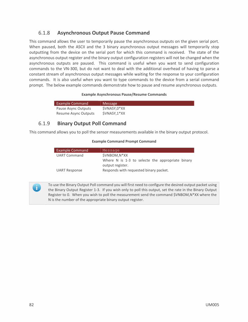
82 UM005
6.1.8 Asynchronous Output Pause Command
This command allows the user to temporarily pause the asynchronous outputs on the given serial port. When paused, both the ASCII and the 3 binary asynchronous output messages will temporarily stop outputting from the device on the serial port for which this command is received. The state of the asynchronous output register and the binary output configuration registers will not be changed when the asynchronous outputs are paused. This command is useful when you want to send configuration commands to the VN-300, but do not want to deal with the additional overhead of having to parse a constant stream of asynchronous output messages while waiting for the response to your configuration commands. It is also useful when you want to type commands to the device from a serial command prompt. The below example commands demonstrate how to pause and resume asynchronous outputs.
Example Asynchronous Pause/Resume Commands
Example Command Message Pause Async Outputs $VNASY,0*XX Resume Async Outputs $VNASY,1*XX
6.1.9 Binary Output Poll Command
This command allows you to poll the sensor measurements available in the binary output protocol.
Example Command Prompt Command
Example Command Message
UART Command $VNBOM,N*XX Where N is 1-3 to selecte the appropriate binary output register.
UART Response Responds with requested binary packet.
To use the Binary Output Poll command you will first need to configure the desired output packet using the Binary Output Register 1-3. If you wish only to poll this output, set the rate in the Binary Output Register to 0. When you wish to poll the measurement send the command $VNBOM,N*XX where the N is the number of the appropriate binary output register.
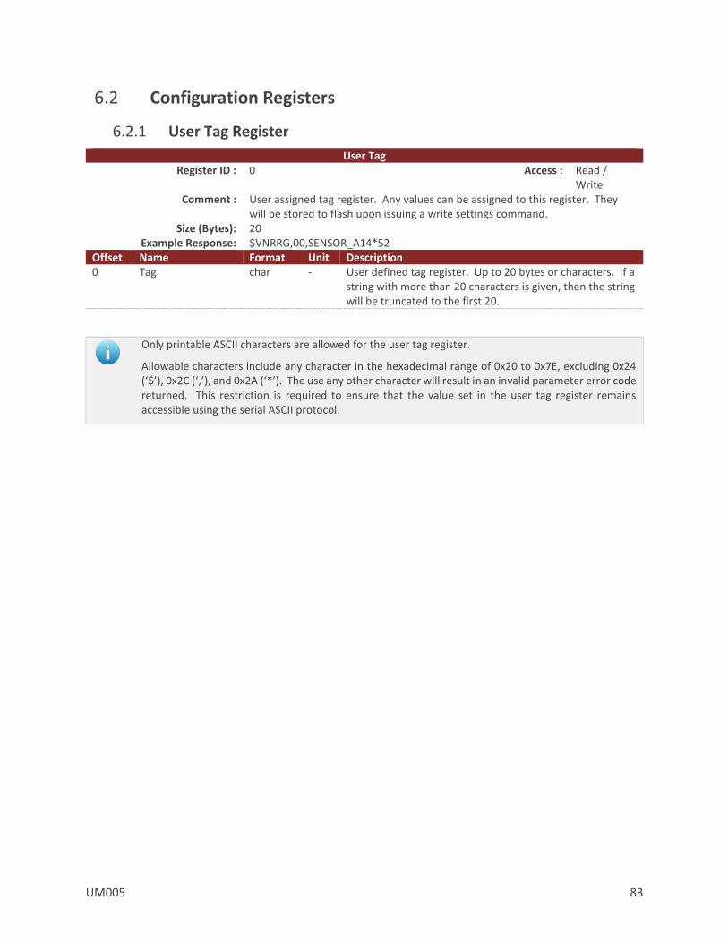
UM005 83
6.2 Configuration Registers
6.2.1 User Tag Register
User Tag Register ID : 0 Access : Read /
Write Comment : User assigned tag register. Any values can be assigned to this register. They
will be stored to flash upon issuing a write settings command. Size (Bytes): 20
Example Response: $VNRRG,00,SENSOR_A14*52 Offset Name Format Unit Description 0 Tag char - User defined tag register. Up to 20 bytes or characters. If a
string with more than 20 characters is given, then the string will be truncated to the first 20.
Only printable ASCII characters are allowed for the user tag register.
Allowable characters include any character in the hexadecimal range of 0x20 to 0x7E, excluding 0x24 (‘$’), 0x2C (‘,’), and 0x2A (‘*’). The use any other character will result in an invalid parameter error code returned. This restriction is required to ensure that the value set in the user tag register remains accessible using the serial ASCII protocol.

84 UM005
6.2.2 Model Number Register
Model Number Register ID : 1 Access : Read Only Comment : Model Number
Size (Bytes): 24 Example Response: $VNRRG,01,VN-310*58
Offset Name Format Unit Description 0 Product
Name char - Product name. Max 24 characters.
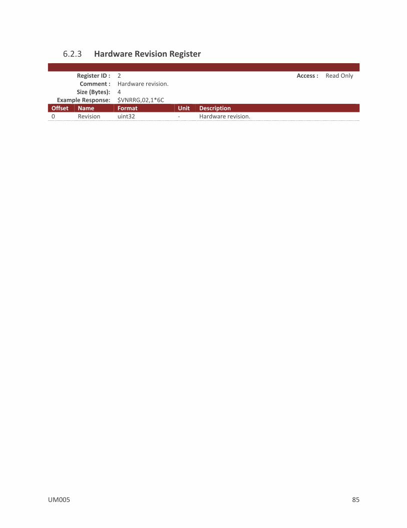
UM005 85
6.2.3 Hardware Revision Register
Register ID : 2 Access : Read Only Comment : Hardware revision.
Size (Bytes): 4 Example Response: $VNRRG,02,1*6C
Offset Name Format Unit Description 0 Revision uint32 - Hardware revision.
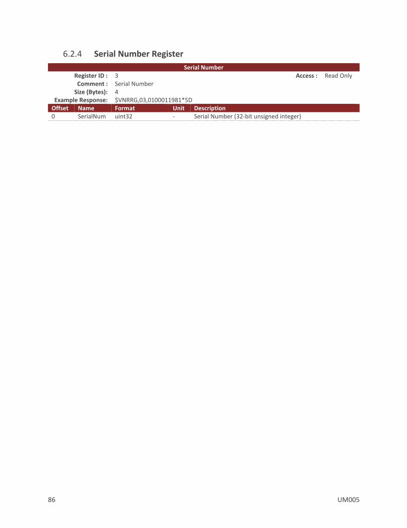
86 UM005
6.2.4 Serial Number Register
Serial Number Register ID : 3 Access : Read Only Comment : Serial Number
Size (Bytes): 4 Example Response: $VNRRG,03,0100011981*5D
Offset Name Format Unit Description 0 SerialNum uint32 - Serial Number (32-bit unsigned integer)
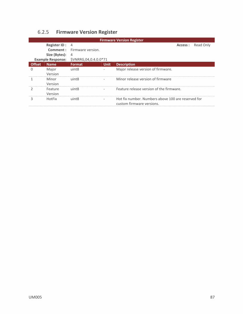
UM005 87
6.2.5 Firmware Version Register
Firmware Version Register Register ID : 4 Access : Read Only Comment : Firmware version.
Size (Bytes): 4 Example Response: $VNRRG,04,0.4.0.0*71
Offset Name Format Unit Description 0 Major
Version uint8 - Major release version of firmware.
1 Minor Version
uint8 - Minor release version of firmware
2 Feature Version
uint8 - Feature release version of the firmware.
3 HotFix uint8 - Hot fix number. Numbers above 100 are reserved for custom firmware versions.
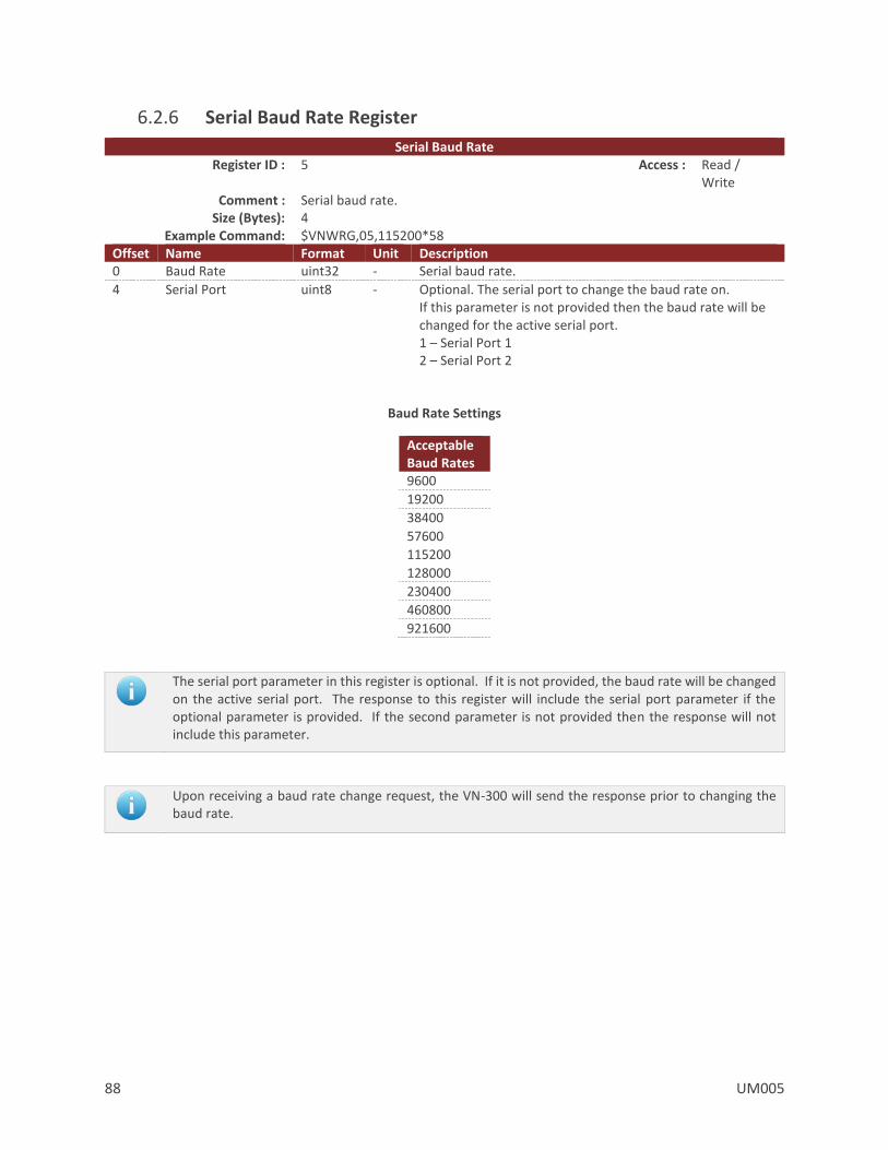
88 UM005
6.2.6 Serial Baud Rate Register
Serial Baud Rate Register ID : 5 Access : Read /
Write Comment : Serial baud rate.
Size (Bytes): 4 Example Command: $VNWRG,05,115200*58
Offset Name Format Unit Description 0 Baud Rate uint32 - Serial baud rate.
4 Serial Port uint8 - Optional. The serial port to change the baud rate on. If this parameter is not provided then the baud rate will be changed for the active serial port. 1 – Serial Port 1 2 – Serial Port 2
Baud Rate Settings
Acceptable Baud Rates 9600
19200
38400
57600
115200
128000
230400
460800
921600
The serial port parameter in this register is optional. If it is not provided, the baud rate will be changed on the active serial port. The response to this register will include the serial port parameter if the optional parameter is provided. If the second parameter is not provided then the response will not include this parameter.
Upon receiving a baud rate change request, the VN-300 will send the response prior to changing the baud rate.
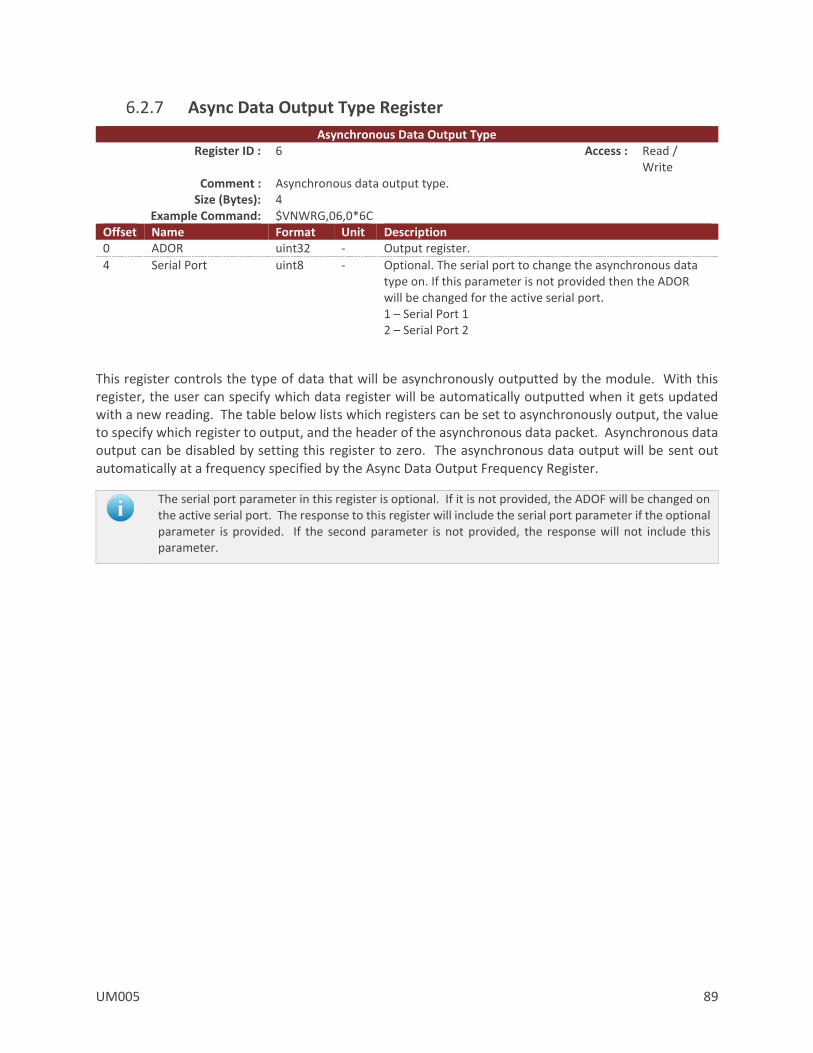
UM005 89
6.2.7 Async Data Output Type Register
Asynchronous Data Output Type Register ID : 6 Access : Read /
Write Comment : Asynchronous data output type.
Size (Bytes): 4 Example Command: $VNWRG,06,0*6C
Offset Name Format Unit Description 0 ADOR uint32 - Output register.
4 Serial Port uint8 - Optional. The serial port to change the asynchronous data type on. If this parameter is not provided then the ADOR will be changed for the active serial port. 1 – Serial Port 1 2 – Serial Port 2
This register controls the type of data that will be asynchronously outputted by the module. With this register, the user can specify which data register will be automatically outputted when it gets updated with a new reading. The table below lists which registers can be set to asynchronously output, the value to specify which register to output, and the header of the asynchronous data packet. Asynchronous data output can be disabled by setting this register to zero. The asynchronous data output will be sent out automatically at a frequency specified by the Async Data Output Frequency Register.
The serial port parameter in this register is optional. If it is not provided, the ADOF will be changed on the active serial port. The response to this register will include the serial port parameter if the optional parameter is provided. If the second parameter is not provided, the response will not include this parameter.
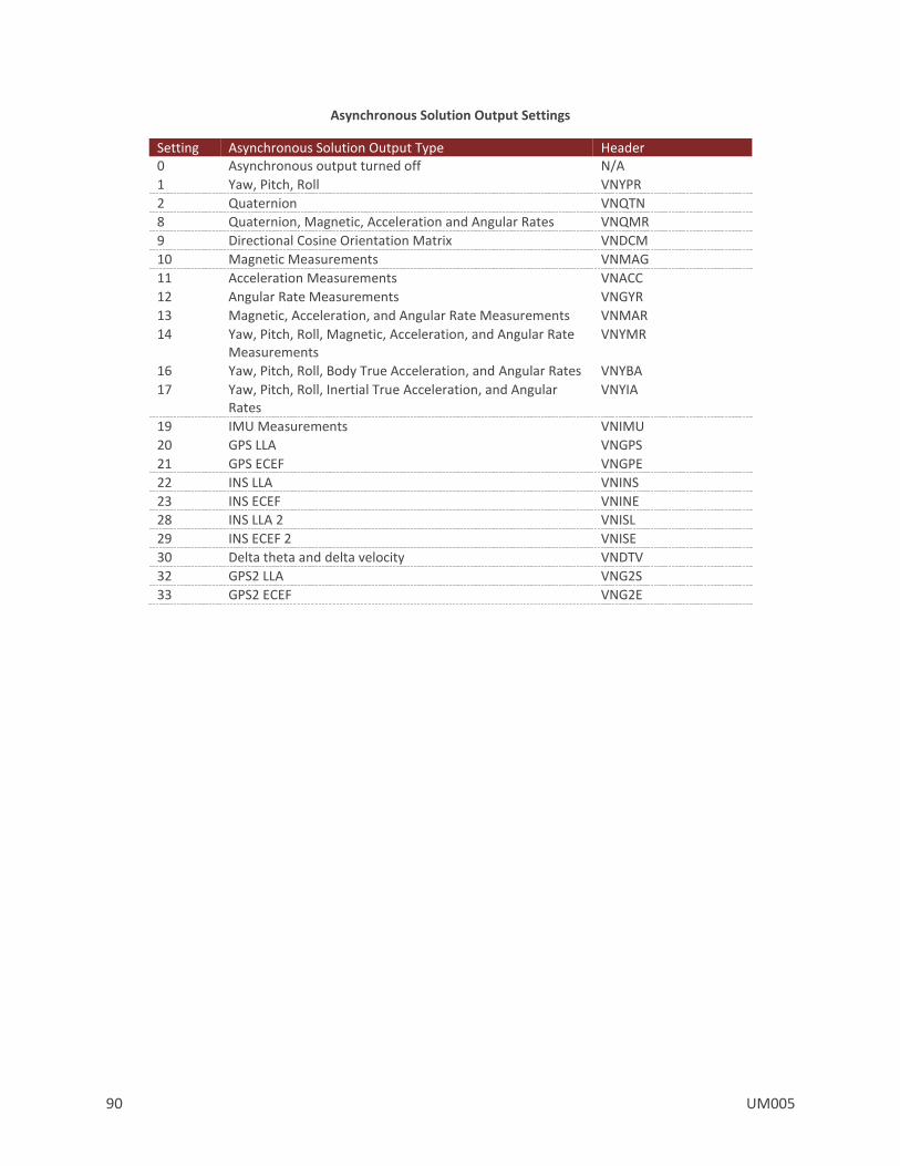
90 UM005
Asynchronous Solution Output Settings
Setting Asynchronous Solution Output Type Header 0 Asynchronous output turned off N/A
1 Yaw, Pitch, Roll VNYPR
2 Quaternion VNQTN
8 Quaternion, Magnetic, Acceleration and Angular Rates VNQMR
9 Directional Cosine Orientation Matrix VNDCM
10 Magnetic Measurements VNMAG
11 Acceleration Measurements VNACC
12 Angular Rate Measurements VNGYR
13 Magnetic, Acceleration, and Angular Rate Measurements VNMAR
14 Yaw, Pitch, Roll, Magnetic, Acceleration, and Angular Rate Measurements
VNYMR
16 Yaw, Pitch, Roll, Body True Acceleration, and Angular Rates VNYBA
17 Yaw, Pitch, Roll, Inertial True Acceleration, and Angular Rates
VNYIA
19 IMU Measurements VNIMU
20 GPS LLA VNGPS
21 GPS ECEF VNGPE
22 INS LLA VNINS
23 INS ECEF VNINE
28 INS LLA 2 VNISL
29 INS ECEF 2 VNISE
30 Delta theta and delta velocity VNDTV
32 GPS2 LLA VNG2S
33 GPS2 ECEF VNG2E

UM005 91
6.2.8 Async Data Output Frequency Register
Asynchronous Data Output Frequency Register ID : 7 Access : Read /
Write Comment : Asynchronous data output frequency.
Size (Bytes): 4 Example Command: $VNWRG,07,40*59
Offset Name Format Unit Description 0 ADOF uint32 Hz Output frequency.
4 Serial Port uint8 - Optional. The serial port to change the asynchronous data type frequency on. If this parameter is not provided then the ADOF will be changed for the active serial port. 1 – Serial Port 1 2 – Serial Port 2
ADOR Data Rates
Acceptable Data Rates (Hz)
1
2
4
5
10
20
25
40
50
100
200
The serial port parameter in this register is optional. If it is not provided, the ADOF will be changed on the active serial port. The response to this register will include the serial port parameter if the optional parameter is provided. If the second parameter is not provided, the response will not include this parameter.

92 UM005
6.2.9 Synchronization Control
Synchronization Control Register ID : 32 Access : Read / Write
Comment : Contains parameters which allow the timing of the VN-300 to be synchronized with external devices.
Size (Bytes): 20 Example Response: $VNRRG,32,3,0,0,0,6,1,0,100000000,0*6B
Offset Name Format Unit Description 0 SyncInMode uint8 - Input signal synchronization mode
1 SyncInEdge uint8 - Input signal synchronization edge selection
2 SyncInSkipFactor uint16 - Input signal trigger skip factor
4 RESERVED uint32 - Reserved for future use. Defaults to 0.
8 SyncOutMode uint8 - Output synchronization signal mode
9 SyncOutPolarity uint8 - Output synchronization signal polarity
10 SyncOutSkipFactor uint16 - Output synchronization signal skip factor
12 SyncOutPulseWidth uint32 ns Output synchronization signal pulse width
16 RESERVED uint32 - Reserved for future use. Defaults to 0.
SyncInMode
The SyncInMode register controls the behavior of the SyncIn event. If the mode is set to COUNT then the internal clock will be used to control the IMU sampling. If SyncInMode is set to IMU then the IMU sampling loop will run on a SyncIn event. The relationship between the SyncIn event and a SyncIn trigger is defined by the SyncInEdge and SyncInSkipFactor parameters. If set to ASYNC then the VN-300 will output asynchronous serial messages upon each trigger event.
SyncIn Mode
Mode Pin Value Description
COUNT SYNC_IN 3 Count number of trigger events on SYNC_IN.
IMU SYNC_IN 4 Start IMU sampling on trigger of SYNC_IN.
ASYNC SYNC_IN 5 Output asynchronous message on trigger of SYNC_IN.
ASYNC3 SYNC_IN 6 Output asynchronous or binary messages configured with a rate of 0 to output on trigger of SYNC_IN.
In ASYNC3 mode messages configured with an output rate = 0 are output each time the appropriate transistion edge of the SyncIn pin is captured according to the edge settings in the SyncInEdge field. Messages configured with output rate > 0 are not affected by the SyncIn puse. This applies to the ASCII Async message set by the Async Data Output Register, the user configurate binary output messages set by the Binary Output Registers, as well as the NMEA messages configured by the NMEA Output Registers.
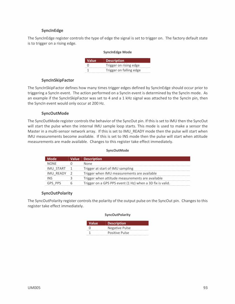
UM005 93
SyncInEdge
The SyncInEdge register controls the type of edge the signal is set to trigger on. The factory default state is to trigger on a rising edge.
SyncInEdge Mode
Value Description 0 Trigger on rising edge
1 Trigger on falling edge
SyncInSkipFactor
The SyncInSkipFactor defines how many times trigger edges defined by SyncInEdge should occur prior to triggering a SyncIn event. The action performed on a SyncIn event is determined by the SyncIn mode. As an example if the SyncInSkipFactor was set to 4 and a 1 kHz signal was attached to the SyncIn pin, then the SyncIn event would only occur at 200 Hz.
SyncOutMode
The SyncOutMode register controls the behavior of the SyncOut pin. If this is set to IMU then the SyncOut will start the pulse when the internal IMU sample loop starts. This mode is used to make a sensor the Master in a multi-sensor network array. If this is set to IMU_READY mode then the pulse will start when IMU measurements become available. If this is set to INS mode then the pulse will start when attitude measurements are made available. Changes to this register take effect immediately.
SyncOutMode
Mode Value Description NONE 0 None
IMU_START 1 Trigger at start of IMU sampling
IMU_READY 2 Trigger when IMU measurements are available
INS 3 Trigger when attitude measurements are available
GPS_PPS 6 Trigger on a GPS PPS event (1 Hz) when a 3D fix is valid.
SyncOutPolarity
The SyncOutPolarity register controls the polarity of the output pulse on the SyncOut pin. Changes to this register take effect immediately.
SyncOutPolarity
Value Description 0 Negative Pulse
1 Positive Pulse

94 UM005
SyncOutSkipFactor
The SyncOutSkipFactor defines how many times the sync out event should be skipped before actually triggering the SyncOut pin.
SyncOutPulseWidth
The SyncOutPulseWidth field controls the desired width of the SyncOut pulse. The default value is 100,000,000 (100 ms).
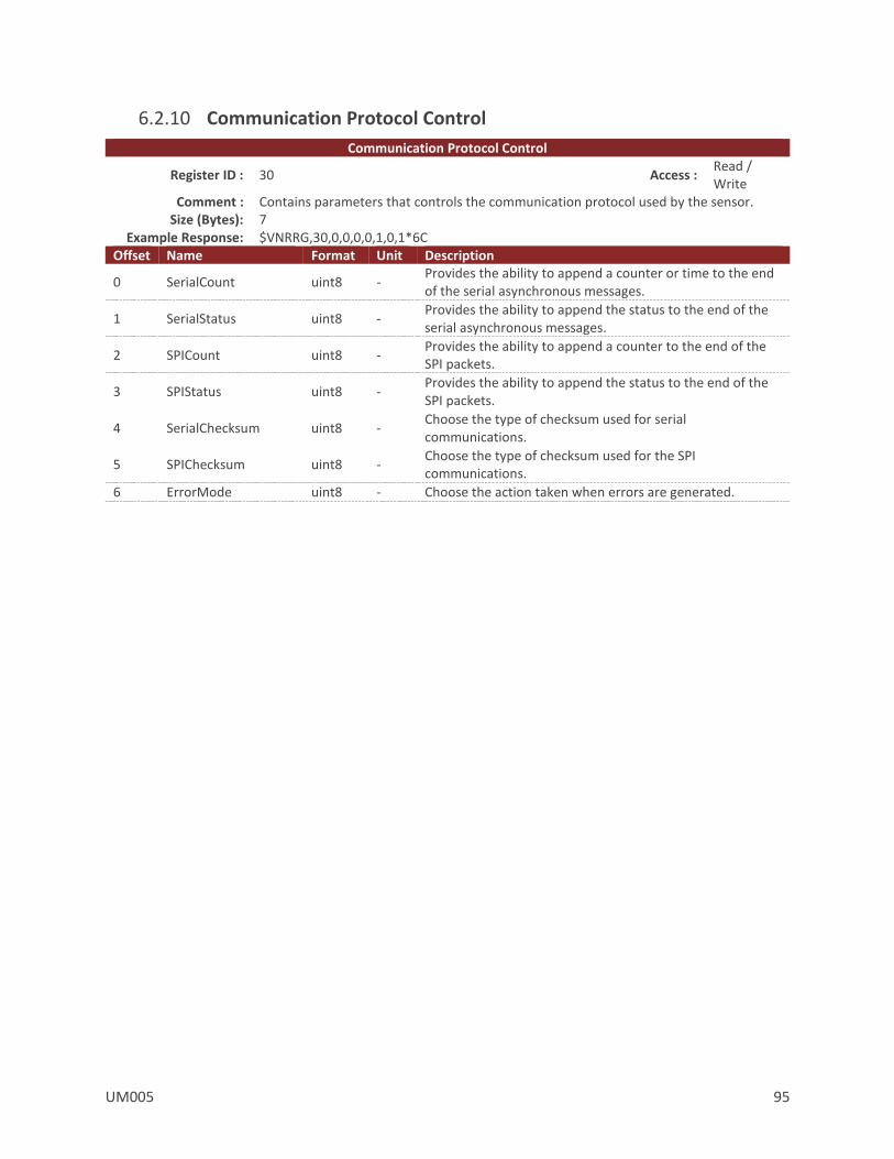
UM005 95
6.2.10 Communication Protocol Control
Communication Protocol Control
Register ID : 30 Access : Read / Write
Comment : Contains parameters that controls the communication protocol used by the sensor. Size (Bytes): 7
Example Response: $VNRRG,30,0,0,0,0,1,0,1*6C Offset Name Format Unit Description
0 SerialCount uint8 - Provides the ability to append a counter or time to the end of the serial asynchronous messages.
1 SerialStatus uint8 - Provides the ability to append the status to the end of the serial asynchronous messages.
2 SPICount uint8 - Provides the ability to append a counter to the end of the SPI packets.
3 SPIStatus uint8 - Provides the ability to append the status to the end of the SPI packets.
4 SerialChecksum uint8 - Choose the type of checksum used for serial communications.
5 SPIChecksum uint8 - Choose the type of checksum used for the SPI communications.
6 ErrorMode uint8 - Choose the action taken when errors are generated.
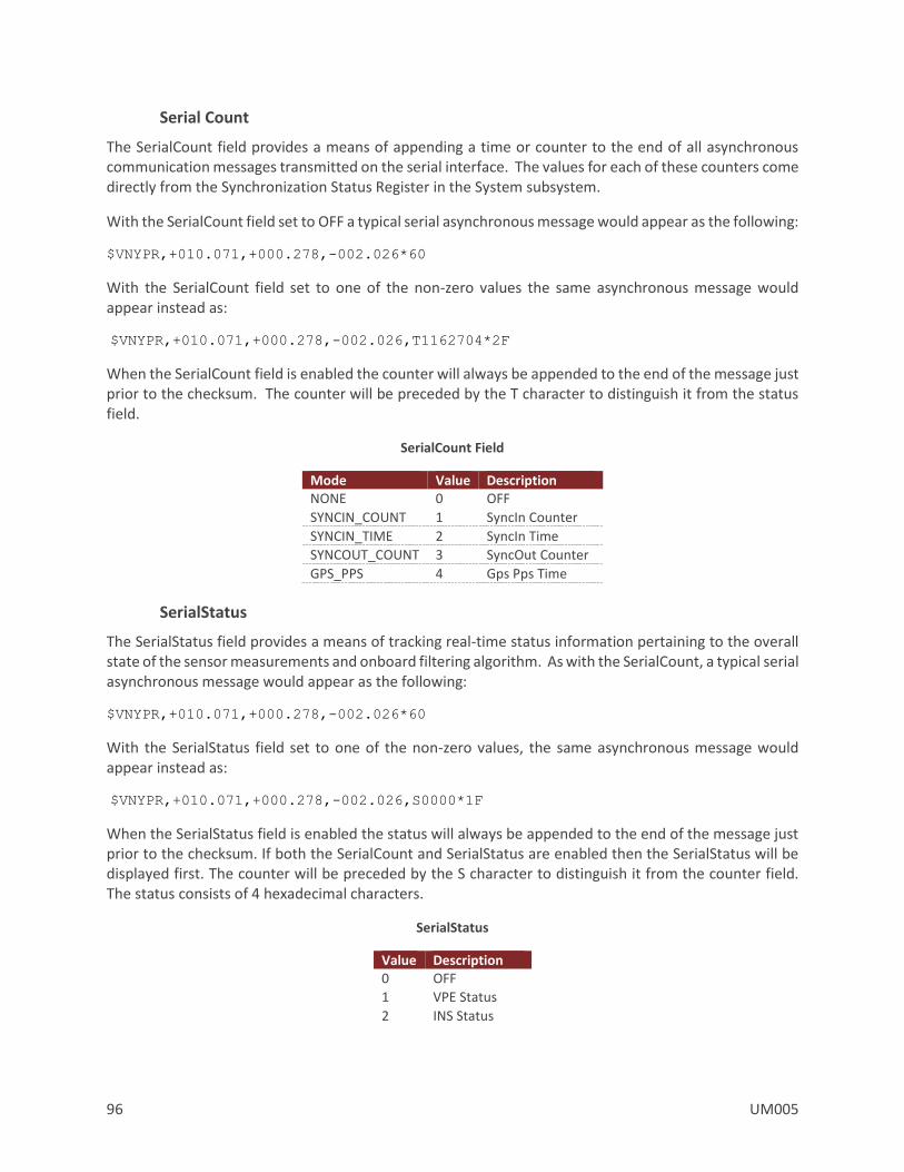
96 UM005
Serial Count
The SerialCount field provides a means of appending a time or counter to the end of all asynchronous communication messages transmitted on the serial interface. The values for each of these counters come directly from the Synchronization Status Register in the System subsystem.
With the SerialCount field set to OFF a typical serial asynchronous message would appear as the following:
$VNYPR,+010.071,+000.278,-002.026*60
With the SerialCount field set to one of the non-zero values the same asynchronous message would appear instead as:
$VNYPR,+010.071,+000.278,-002.026,T1162704*2F
When the SerialCount field is enabled the counter will always be appended to the end of the message just prior to the checksum. The counter will be preceded by the T character to distinguish it from the status field.
SerialCount Field
Mode Value Description NONE 0 OFF
SYNCIN_COUNT 1 SyncIn Counter
SYNCIN_TIME 2 SyncIn Time
SYNCOUT_COUNT 3 SyncOut Counter
GPS_PPS 4 Gps Pps Time
SerialStatus
The SerialStatus field provides a means of tracking real-time status information pertaining to the overall state of the sensor measurements and onboard filtering algorithm. As with the SerialCount, a typical serial asynchronous message would appear as the following:
$VNYPR,+010.071,+000.278,-002.026*60
With the SerialStatus field set to one of the non-zero values, the same asynchronous message would appear instead as:
$VNYPR,+010.071,+000.278,-002.026,S0000*1F
When the SerialStatus field is enabled the status will always be appended to the end of the message just prior to the checksum. If both the SerialCount and SerialStatus are enabled then the SerialStatus will be displayed first. The counter will be preceded by the S character to distinguish it from the counter field. The status consists of 4 hexadecimal characters.
SerialStatus
Value Description 0 OFF
1 VPE Status
2 INS Status

UM005 97
SPICount
The SPICount field provides a means of appending a time or counter to the end of all SPI packets. The values for each of these counters come directly from the Synchronization Status Register.
SPICount Field
Mode Value Description NONE 0 OFF
SYNCIN_COUNT 1 SyncIn Counter
SYNCIN_TIME 2 SyncIn Time
SYNCOUT_COUNT 3 SyncOut Counter
GPS_PPS 4 Gps Pps Time
SPIStatus
The AsyncStatus field provides a means of tracking real-time status information pertaining to the overall state of the sensor measurements and onboard filtering algorithm. This information is very useful in situations where action must be taken when certain crucial events happen such as the detection of gyro saturation or magnetic interference.
SPIStatus
Value Description 0 OFF
1 VPE Status
2 INS Status
SerialChecksum
This field controls the type of checksum used for the serial communications. Normally the VN-300 uses an 8-bit checksum identical to the type used for normal GPS NMEA packets. This form of checksum however offers only a limited means of error checking. As an alternative a full 16-bit CRC (CRC16-CCITT with polynomial = 0x07) is also offered. The 2-byte CRC value is printed using 4 hexadecimal digits.
SerialChecksum
Value Description 1 8-Bit Checksum
3 16-Bit CRC
SPIChecksum
This field controls the type of checksum used for the SPI communications. The checksum is appended to the end of the binary data packet. The 16-bit CRC is identical to the one described above for the SerialChecksum.
SPIChecksum
Value Description 0 OFF
1 8-Bit Checksum
3 16-Bit CRC
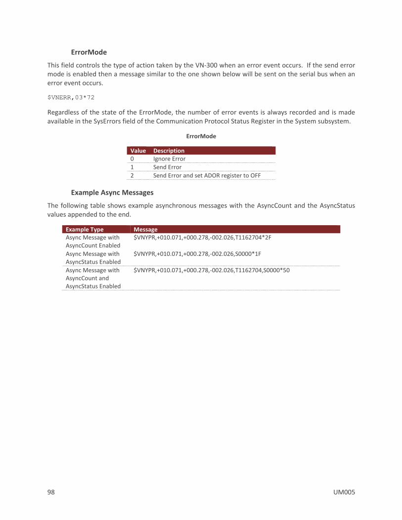
98 UM005
ErrorMode
This field controls the type of action taken by the VN-300 when an error event occurs. If the send error mode is enabled then a message similar to the one shown below will be sent on the serial bus when an error event occurs.
$VNERR,03*72
Regardless of the state of the ErrorMode, the number of error events is always recorded and is made available in the SysErrors field of the Communication Protocol Status Register in the System subsystem.
ErrorMode
Value Description 0 Ignore Error
1 Send Error
2 Send Error and set ADOR register to OFF
Example Async Messages
The following table shows example asynchronous messages with the AsyncCount and the AsyncStatus values appended to the end.
Example Type Message Async Message with AsyncCount Enabled
$VNYPR,+010.071,+000.278,-002.026,T1162704*2F
Async Message with AsyncStatus Enabled
$VNYPR,+010.071,+000.278,-002.026,S0000*1F
Async Message with AsyncCount and AsyncStatus Enabled
$VNYPR,+010.071,+000.278,-002.026,T1162704,S0000*50
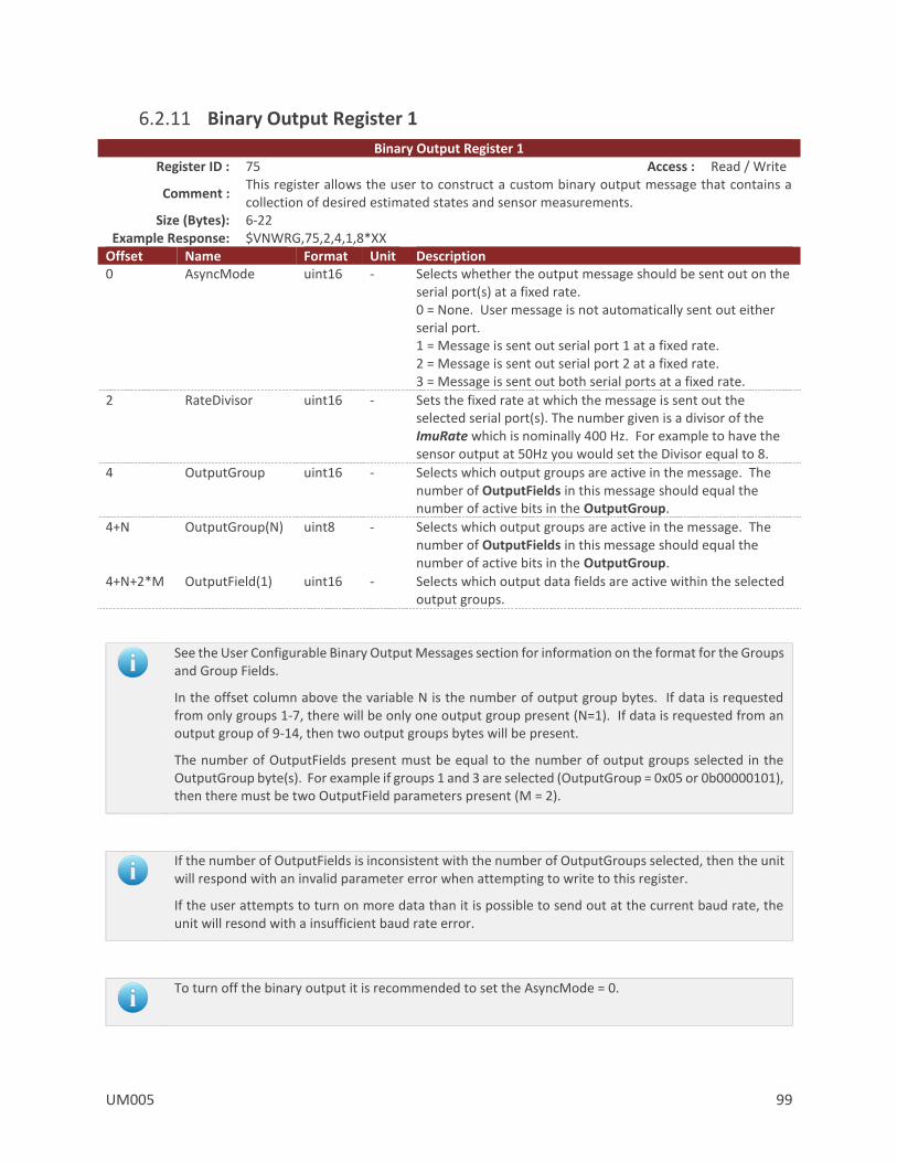
UM005 99
6.2.11 Binary Output Register 1
Binary Output Register 1 Register ID : 75 Access : Read / Write
Comment : This register allows the user to construct a custom binary output message that contains a collection of desired estimated states and sensor measurements.
Size (Bytes): 6-22 Example Response: $VNWRG,75,2,4,1,8*XX
Offset Name Format Unit Description 0 AsyncMode uint16 - Selects whether the output message should be sent out on the
serial port(s) at a fixed rate. 0 = None. User message is not automatically sent out either serial port. 1 = Message is sent out serial port 1 at a fixed rate. 2 = Message is sent out serial port 2 at a fixed rate. 3 = Message is sent out both serial ports at a fixed rate.
2 RateDivisor uint16 - Sets the fixed rate at which the message is sent out the selected serial port(s). The number given is a divisor of the ImuRate which is nominally 400 Hz. For example to have the sensor output at 50Hz you would set the Divisor equal to 8.
4 OutputGroup uint16 - Selects which output groups are active in the message. The number of OutputFields in this message should equal the number of active bits in the OutputGroup.
4+N OutputGroup(N) uint8 - Selects which output groups are active in the message. The number of OutputFields in this message should equal the number of active bits in the OutputGroup.
4+N+2*M OutputField(1) uint16 - Selects which output data fields are active within the selected output groups.
See the User Configurable Binary Output Messages section for information on the format for the Groups and Group Fields.
In the offset column above the variable N is the number of output group bytes. If data is requested from only groups 1-7, there will be only one output group present (N=1). If data is requested from an output group of 9-14, then two output groups bytes will be present.
The number of OutputFields present must be equal to the number of output groups selected in the OutputGroup byte(s). For example if groups 1 and 3 are selected (OutputGroup = 0x05 or 0b00000101), then there must be two OutputField parameters present (M = 2).
If the number of OutputFields is inconsistent with the number of OutputGroups selected, then the unit will respond with an invalid parameter error when attempting to write to this register.
If the user attempts to turn on more data than it is possible to send out at the current baud rate, the unit will resond with a insufficient baud rate error.
To turn off the binary output it is recommended to set the AsyncMode = 0.
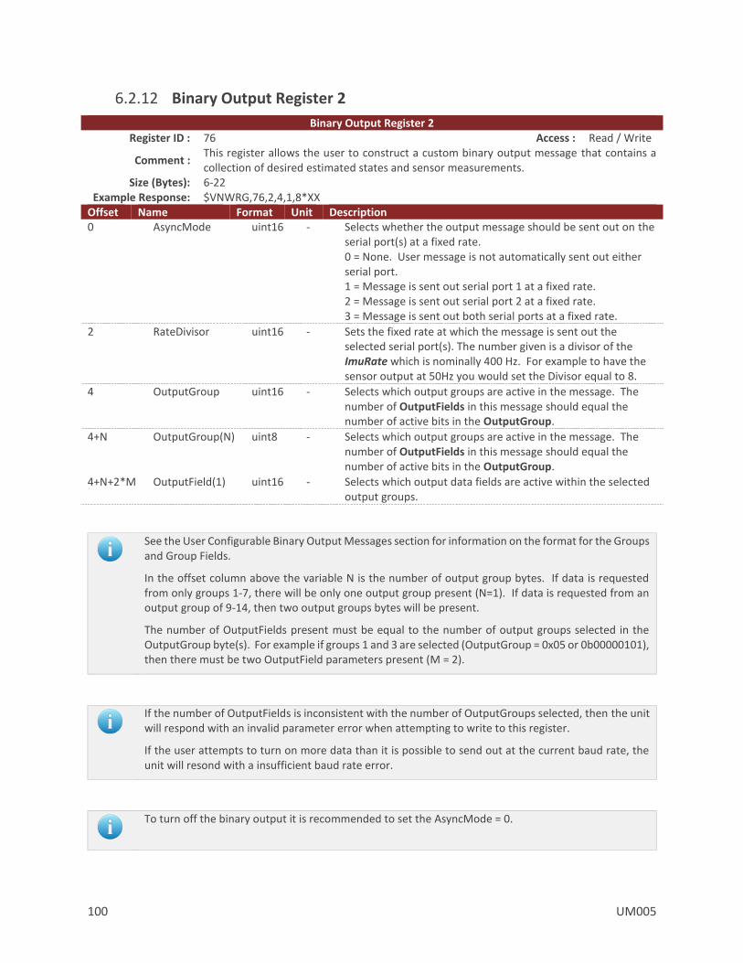
100 UM005
6.2.12 Binary Output Register 2
Binary Output Register 2 Register ID : 76 Access : Read / Write
Comment : This register allows the user to construct a custom binary output message that contains a collection of desired estimated states and sensor measurements.
Size (Bytes): 6-22 Example Response: $VNWRG,76,2,4,1,8*XX
Offset Name Format Unit Description 0 AsyncMode uint16 - Selects whether the output message should be sent out on the
serial port(s) at a fixed rate. 0 = None. User message is not automatically sent out either serial port. 1 = Message is sent out serial port 1 at a fixed rate. 2 = Message is sent out serial port 2 at a fixed rate. 3 = Message is sent out both serial ports at a fixed rate.
2 RateDivisor uint16 - Sets the fixed rate at which the message is sent out the selected serial port(s). The number given is a divisor of the ImuRate which is nominally 400 Hz. For example to have the sensor output at 50Hz you would set the Divisor equal to 8.
4 OutputGroup uint16 - Selects which output groups are active in the message. The number of OutputFields in this message should equal the number of active bits in the OutputGroup.
4+N OutputGroup(N) uint8 - Selects which output groups are active in the message. The number of OutputFields in this message should equal the number of active bits in the OutputGroup.
4+N+2*M OutputField(1) uint16 - Selects which output data fields are active within the selected output groups.
See the User Configurable Binary Output Messages section for information on the format for the Groups and Group Fields.
In the offset column above the variable N is the number of output group bytes. If data is requested from only groups 1-7, there will be only one output group present (N=1). If data is requested from an output group of 9-14, then two output groups bytes will be present.
The number of OutputFields present must be equal to the number of output groups selected in the OutputGroup byte(s). For example if groups 1 and 3 are selected (OutputGroup = 0x05 or 0b00000101), then there must be two OutputField parameters present (M = 2).
If the number of OutputFields is inconsistent with the number of OutputGroups selected, then the unit will respond with an invalid parameter error when attempting to write to this register.
If the user attempts to turn on more data than it is possible to send out at the current baud rate, the unit will resond with a insufficient baud rate error.
To turn off the binary output it is recommended to set the AsyncMode = 0.
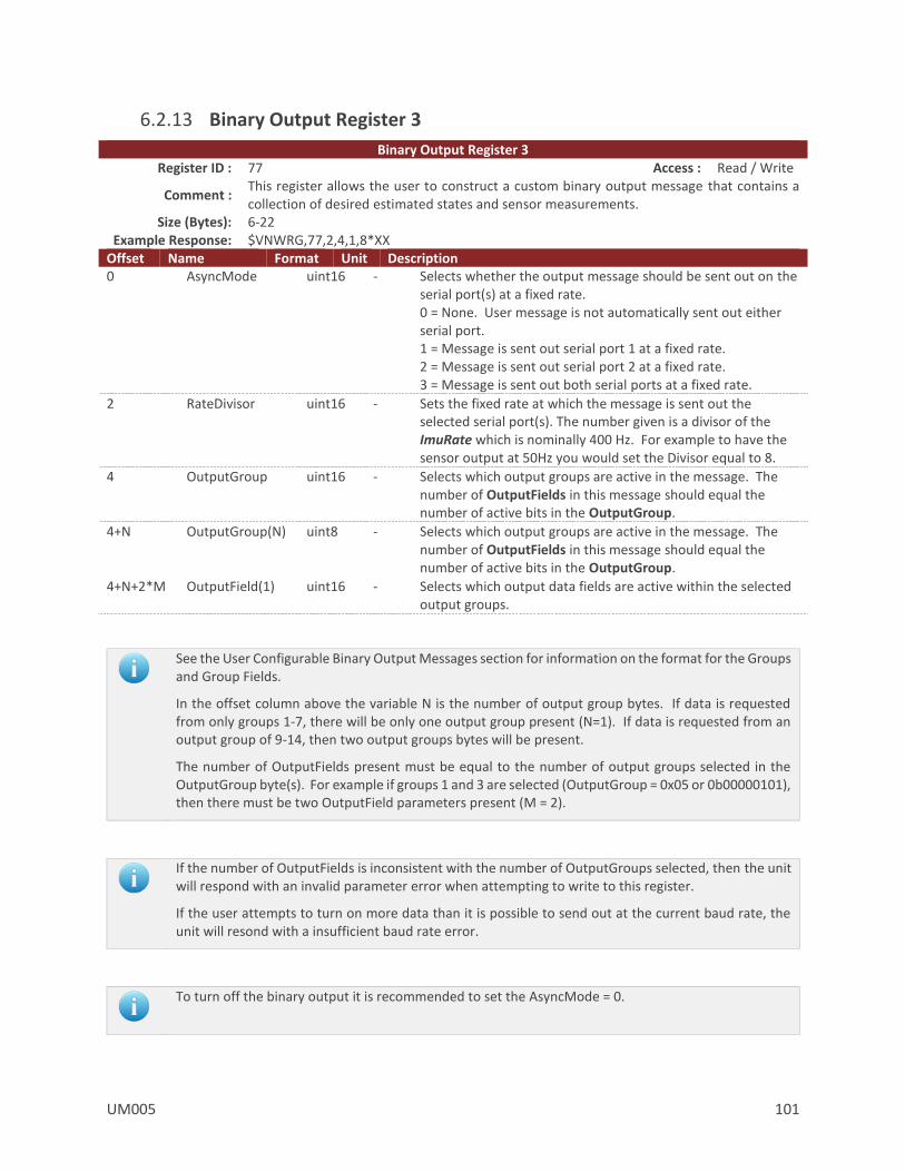
UM005 101
6.2.13 Binary Output Register 3
Binary Output Register 3 Register ID : 77 Access : Read / Write
Comment : This register allows the user to construct a custom binary output message that contains a collection of desired estimated states and sensor measurements.
Size (Bytes): 6-22 Example Response: $VNWRG,77,2,4,1,8*XX
Offset Name Format Unit Description 0 AsyncMode uint16 - Selects whether the output message should be sent out on the
serial port(s) at a fixed rate. 0 = None. User message is not automatically sent out either serial port. 1 = Message is sent out serial port 1 at a fixed rate. 2 = Message is sent out serial port 2 at a fixed rate. 3 = Message is sent out both serial ports at a fixed rate.
2 RateDivisor uint16 - Sets the fixed rate at which the message is sent out the selected serial port(s). The number given is a divisor of the ImuRate which is nominally 400 Hz. For example to have the sensor output at 50Hz you would set the Divisor equal to 8.
4 OutputGroup uint16 - Selects which output groups are active in the message. The number of OutputFields in this message should equal the number of active bits in the OutputGroup.
4+N OutputGroup(N) uint8 - Selects which output groups are active in the message. The number of OutputFields in this message should equal the number of active bits in the OutputGroup.
4+N+2*M OutputField(1) uint16 - Selects which output data fields are active within the selected output groups.
See the User Configurable Binary Output Messages section for information on the format for the Groups and Group Fields.
In the offset column above the variable N is the number of output group bytes. If data is requested from only groups 1-7, there will be only one output group present (N=1). If data is requested from an output group of 9-14, then two output groups bytes will be present.
The number of OutputFields present must be equal to the number of output groups selected in the OutputGroup byte(s). For example if groups 1 and 3 are selected (OutputGroup = 0x05 or 0b00000101), then there must be two OutputField parameters present (M = 2).
If the number of OutputFields is inconsistent with the number of OutputGroups selected, then the unit will respond with an invalid parameter error when attempting to write to this register.
If the user attempts to turn on more data than it is possible to send out at the current baud rate, the unit will resond with a insufficient baud rate error.
To turn off the binary output it is recommended to set the AsyncMode = 0.
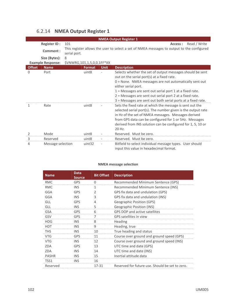
102 UM005
6.2.14 NMEA Output Register 1
NMEA Output Register 1 Register ID : 101 Access : Read / Write
Comment : This register allows the user to select a set of NMEA messages to output to the configured serial port.
Size (Bytes): 8 Example Response: $VNWRG,101,1,5,0,0,1FF*XX
Offset Name Format Unit Description 0 Port uint8 - Selects whether the set of output messages should be sent
out on the serial port(s) at a fixed rate. 0 = None. NMEA messages are not automatically sent out either serial port. 1 = Messages are sent out serial port 1 at a fixed rate. 2 = Messages are sent out serial port 2 at a fixed rate. 3 = Messages are sent out both serial ports at a fixed rate.
1 Rate uint8 - Sets the fixed rate at which the message is sent out the selected serial port(s). The number given is the output rate in Hz of the set of NMEA messages. Messages derived from GPS data can be configured for 1 or 5Hz. Messages derived from INS solution can be configured for 1, 5, 10 or 20 Hz.
2 Mode uint8 - Reserved. Must be zero.
3 Reserved uint8 - Reserved. Must be zero.
4 Message selection uint32 - Bitfield to select individual message types. User should input this value in hexadecimal format.
NMEA message selection
Name Data Source
Bit Offset Description
RMC GPS 0 Recommended Minimum Sentence (GPS)
RMC INS 1 Recommended Minimum Sentence (INS)
GGA GPS 2 GPS fix data and undulation (GPS)
GGA INS 3 GPS fix data and undulation (INS)
GLL GPS 4 Geographic Position (GPS)
GLL INS 5 Geographic Position (INS)
GSA GPS 6 GPS DOP and active satellites
GSV GPS 7 GPS satellites in view
HDG INS 8 Heading
HDT INS 9 Heading, true
THS INS 10 True heading and status
VTG GPS 11 Course over ground and ground speed (GPS)
VTG INS 12 Course over ground and ground speed (INS)
ZDA GPS 13 UTC time and date (GPS)
ZDA INS 14 UTC time and date (INS)
PASHR INS 15 Inertial attitude data
TSS1 INS 16
Reserved 17-31 Reserved for future use. Should be set to zero.

UM005 103
6.2.15 NMEA Output Register 2
NMEA Output Register 2 Register ID : 102 Access : Read / Write
Comment : This register allows the user to select a set of NMEA messages to output to the configured serial port.
Size (Bytes): 8 Example Response: $VNWRG,102,1,5,0,0,1FF*XX
Offset Name Format Unit Description 0 Port uint8 - Selects whether the set of output messages should be sent
out on the serial port(s) at a fixed rate. 0 = None. NMEA messages are not automatically sent out either serial port. 1 = Messages are sent out serial port 1 at a fixed rate. 2 = Messages are sent out serial port 2 at a fixed rate. 3 = Messages are sent out both serial ports at a fixed rate.
1 Rate uint8 - Sets the fixed rate at which the message is sent out the selected serial port(s). The number given is the output rate in Hz of the set of NMEA messages. Messages derived from GPS data can be configured for 1 or 5Hz. Messages derived from INS solution can be configured for 1, 5, 10 or 20 Hz.
2 Mode uint8 - Reserved. Must be zero.
3 Reserved uint8 - Reserved. Must be zero.
4 Message selection uint32 - Bitfield to select individual message types. User should input this value in hexadecimal format.
NMEA message selection
Name Data Source
Bit Offset Description
RMC GPS 0 Recommended Minimum Sentence (GPS)
RMC INS 1 Recommended Minimum Sentence (INS)
GGA GPS 2 GPS fix data and undulation (GPS)
GGA INS 3 GPS fix data and undulation (INS)
GLL GPS 4 Geographic Position (GPS)
GLL INS 5 Geographic Position (INS)
GSA GPS 6 GPS DOP and active satellites
GSV GPS 7 GPS satellites in view
HDG INS 8 Heading
HDT INS 9 Heading, true
THS INS 10 True heading and status
VTG GPS 11 Course over ground and ground speed (GPS)
VTG INS 12 Course over ground and ground speed (INS)
ZDA GPS 13 UTC time and date (GPS)
ZDA INS 14 UTC time and date (INS)
PASHR INS 15 Inertial attitude data
TSS1 INS 16
Reserved 17-31 Reserved for future use. Should be set to zero.
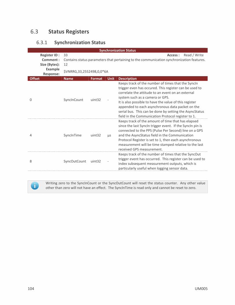
104 UM005
6.3 Status Registers
6.3.1 Synchronization Status
Synchronization Status Register ID : 33 Access : Read / Write Comment : Contains status parameters that pertaining to the communication synchronization features.
Size (Bytes): 12 Example
Response: $VNRRG,33,2552498,0,0*6A
Offset Name Format Unit Description
0 SyncInCount uint32 -
Keeps track of the number of times that the SyncIn trigger even has occured. This register can be used to correlate the attitude to an event on an external system such as a camera or GPS. It is also possible to have the value of this register appended to each asynchronous data packet on the serial bus. This can be done by setting the AsyncStatus field in the Communication Protocol register to 1.
4 SyncInTime uint32 µs
Keeps track of the amount of time that has elapsed since the last SyncIn trigger event. If the SyncIn pin is connected to the PPS (Pulse Per Second) line on a GPS and the AsyncStatus field in the Communication Protocol Register is set to 1, then each asynchronous measurement will be time stamped relative to the last received GPS measurement.
8 SyncOutCount uint32 -
Keeps track of the number of times that the SyncOut trigger event has occurred. This register can be used to index subsequent measurement outputs, which is particularly useful when logging sensor data.
Writing zero to the SyncInCount or the SyncOutCount will reset the status counter. Any other value other than zero will not have an effect. The SyncInTime is read only and cannot be reset to zero.
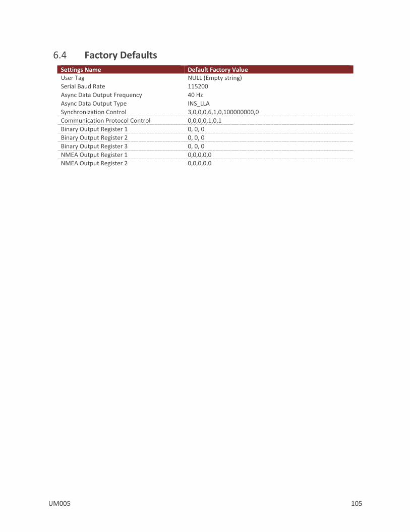
UM005 105
6.4 Factory Defaults Settings Name Default Factory Value User Tag NULL (Empty string)
Serial Baud Rate 115200
Async Data Output Frequency 40 Hz
Async Data Output Type INS_LLA
Synchronization Control 3,0,0,0,6,1,0,100000000,0
Communication Protocol Control 0,0,0,0,1,0,1
Binary Output Register 1 0, 0, 0
Binary Output Register 2 0, 0, 0
Binary Output Register 3 0, 0, 0
NMEA Output Register 1 0,0,0,0,0
NMEA Output Register 2 0,0,0,0,0

106 UM005
6.5 Command Prompt
The command prompt provides a fast and simple means of configuring and monitoring the status of the sensor by typing commands to the unit using the serial port.
6.5.1 List Available Commands
Commands for the System subsystem can be accessed by typing in ‘system’ at the command prompt. To view all available commands, type ‘system ?’. Below is a view of a terminal window showing a list of the available commands.
system ?
System Module Commands:
Command: Description:
-------- -----------------------------------------
info Device specific information such as serial number and firmware version.
comm Information on the communication interfaces.
errors Overview of the logged system errors.
reset Perform a software reset on the unit.
save Save register settings to flash memory.
restore Restore register settings to their factory default state.
6.5.2 System Info
system info
-------------------------------- System Info ---------------------------------
Hardware:
Product Model: VN-310
Serial Number: 100013003
MCU Serial Number: 34323439044731322F002100
Hardware Revision: 2
Form Revision: 1
Software:
Firmware Version: 0.3.0.0
Revision: 691
Build Number: 2813
--------------------------------------------------------------------------------
6.5.3 System Comm
system comm
---------------------- System Communication Interfaces -----------------------
Communication Stats:
Serial Messages Parsed : 29
Spi Messages Parsed : 0
Max Serial RX Buffer Usage : 0
Max Serial TX Buffer Usage : 4
Max Spi RX Buffer Usage : 0
Max Spi TX Buffer Usage : 0

UM005 107
Current Serial 1 TX Bandwidth Usage : 00.0
Current Serial 2 TX Bandwidth Usage : 49.3
Max Serial 1 TX Bandwidth Usage : 49.3
Max Serial 2 TX Bandwidth Usage : 50.5
Min Serial 1 TX Bandwidth Usage : 00.0
Min Serial 2 TX Bandwidth Usage : 48.1
--------------------------------------------------------------------------------
6.5.4 System Errors
system errors
------------------------------- System Errors --------------------------------
Hard Fault Exceptions : 0
Serial Input Buffer Overflow : 0
Serial Output Buffer Overflow : 0
Serial Insufficient Bandwidth : 0
Invalid Checksums : 6
Invalid Commands : 2
Input Error - Too Few Parameters : 0
Input Error - Too Many Parameters : 0
Input Error - Invalid Parameter : 0
Input Error - Invalid Register : 0
Input Error - Unauthorized Access : 2
Input Error - Watchdog Reset : 0
--------------------------------------------------------------------------------
6.5.5 System Reset
system reset
6.5.6 System Save
system save

108 UM005
7 IMU Subsystem
7.1 IMU Measurement Registers
7.1.1 IMU Measurements
This register provides direct access to the calibrated magnetometer, accelerometer, gyro, barometric pressure, and temperature measurements available from the onboard IMU.
IMU Measurements Register ID : 54 Async Header : IMU Access : Read Only
Comment : Provides the calibrated IMU measurements including barometric pressure.
Size (Bytes): 44
Example Read Response:
$VNRRG,54,-02.0841,+00.6045,+02.8911,+00.381,-00.154,-09.657,-00.005683, +00.000262,+00.001475,+21.6,+00099.761*5B
Offset Name Format Unit Description 0 MagX float Gauss Uncompensated Magnetic X-axis.
4 MagY float Gauss Uncompensated Magnetic Y-axis.
8 MagZ float Gauss Uncompensated Magnetic Z-axis.
12 AccelX float m/s2 Uncompensated Acceleration X-axis.
16 AccelY float m/s2 Uncompensated Acceleration Y-axis.
20 AccelZ float m/s2 Uncompensated Acceleration Z-axis.
24 GyroX float rad/s Uncompensated Angular rate X-axis.
28 GyroY float rad/s Uncompensated Angular rate Y-axis.
32 GyroZ float rad/s Uncompensated Angular rate Z-axis.
36 Temp float C IMU Temperature.
40 Pressure float kPa Barometric pressure.
You can configure the device to output this register at a fixed rate using the Async Data Output Type Register in the System subsystem. Once configured the data in this register will be sent out with the $VNIMU header.
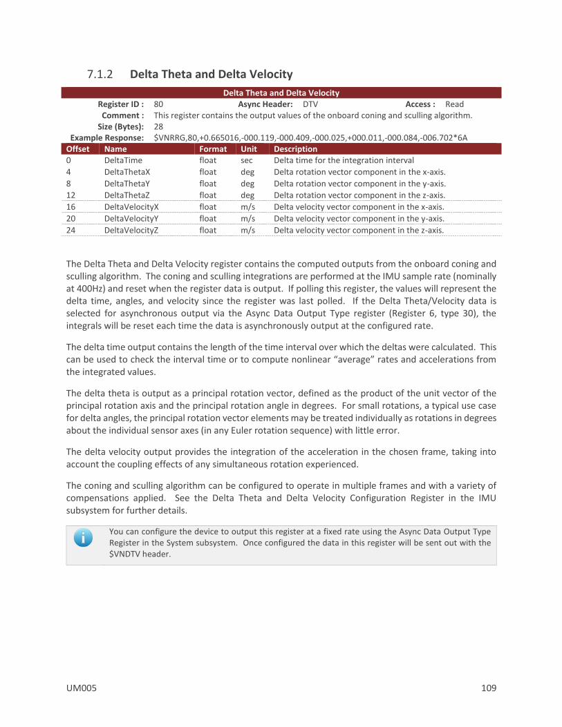
UM005 109
7.1.2 Delta Theta and Delta Velocity
Delta Theta and Delta Velocity Register ID : 80 Async Header: DTV Access : Read Comment : This register contains the output values of the onboard coning and sculling algorithm.
Size (Bytes): 28 Example Response: $VNRRG,80,+0.665016,-000.119,-000.409,-000.025,+000.011,-000.084,-006.702*6A
Offset Name Format Unit Description 0 DeltaTime float sec Delta time for the integration interval
4 DeltaThetaX float deg Delta rotation vector component in the x-axis.
8 DeltaThetaY float deg Delta rotation vector component in the y-axis.
12 DeltaThetaZ float deg Delta rotation vector component in the z-axis.
16 DeltaVelocityX float m/s Delta velocity vector component in the x-axis.
20 DeltaVelocityY float m/s Delta velocity vector component in the y-axis.
24 DeltaVelocityZ float m/s Delta velocity vector component in the z-axis.
The Delta Theta and Delta Velocity register contains the computed outputs from the onboard coning and sculling algorithm. The coning and sculling integrations are performed at the IMU sample rate (nominally at 400Hz) and reset when the register data is output. If polling this register, the values will represent the delta time, angles, and velocity since the register was last polled. If the Delta Theta/Velocity data is selected for asynchronous output via the Async Data Output Type register (Register 6, type 30), the integrals will be reset each time the data is asynchronously output at the configured rate.
The delta time output contains the length of the time interval over which the deltas were calculated. This can be used to check the interval time or to compute nonlinear “average” rates and accelerations from the integrated values.
The delta theta is output as a principal rotation vector, defined as the product of the unit vector of the principal rotation axis and the principal rotation angle in degrees. For small rotations, a typical use case for delta angles, the principal rotation vector elements may be treated individually as rotations in degrees about the individual sensor axes (in any Euler rotation sequence) with little error.
The delta velocity output provides the integration of the acceleration in the chosen frame, taking into account the coupling effects of any simultaneous rotation experienced.
The coning and sculling algorithm can be configured to operate in multiple frames and with a variety of compensations applied. See the Delta Theta and Delta Velocity Configuration Register in the IMU subsystem for further details.
You can configure the device to output this register at a fixed rate using the Async Data Output Type Register in the System subsystem. Once configured the data in this register will be sent out with the $VNDTV header.
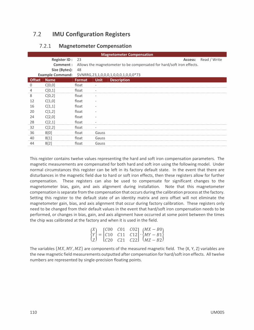
110 UM005
7.2 IMU Configuration Registers
7.2.1 Magnetometer Compensation
Magnetometer Compensation Register ID : 23 Access: Read / Write Comment : Allows the magnetometer to be compensated for hard/soft iron effects.
Size (Bytes): 48 Example Command: $VNRRG,23,1,0,0,0,1,0,0,0,1,0,0,0*73
Offset Name Format Unit Description 0 C[0,0] float -
4 C[0,1] float -
8 C[0,2] float -
12 C[1,0] float -
16 C[1,1] float -
20 C[1,2] float -
24 C[2,0] float -
28 C[2,1] float -
32 C[2,2] float -
36 B[0] float Gauss
40 B[1] float Gauss
44 B[2] float Gauss
This register contains twelve values representing the hard and soft iron compensation parameters. The magnetic measurements are compensated for both hard and soft iron using the following model. Under normal circumstances this register can be left in its factory default state. In the event that there are disturbances in the magnetic field due to hard or soft iron effects, then these registers allow for further compensation. These registers can also be used to compensate for significant changes to the magnetometer bias, gain, and axis alignment during installation. Note that this magnetometer compensation is separate from the compensation that occurs during the calibration process at the factory. Setting this register to the default state of an identity matrix and zero offset will not eliminate the magnetometer gain, bias, and axis alignment that occur during factory calibration. These registers only need to be changed from their default values in the event that hard/soft iron compensation needs to be performed, or changes in bias, gain, and axis alignment have occurred at some point between the times the chip was calibrated at the factory and when it is used in the field.
𝑋𝑌𝑍 = [
𝐶00 𝐶01 𝐶02𝐶10 𝐶11 𝐶12𝐶20 𝐶21 𝐶22
] ∙ 𝑀𝑋 − 𝐵0𝑀𝑌 − 𝐵1𝑀𝑍 − 𝐵2
The variables 𝑀𝑋,𝑀𝑌,𝑀𝑍 are components of the measured magnetic field. The X, Y, Z variables are the new magnetic field measurements outputted after compensation for hard/soft iron effects. All twelve numbers are represented by single-precision floating points.

UM005 111
7.2.2 Acceleration Compensation
Accelerometer Compensation Register ID : 25 Access : Read / Write
Comment : Allows the accelerometer to be further compensated for scale factor, misalignment, and bias errors.
Size (Bytes): 48 Example Command: $VNRRG,25,1,0,0,0,1,0,0,0,1,0,0,0*75
Offset Name Format Unit Description 0 C[0,0] float -
4 C[0,1] float -
8 C[0,2] float -
12 C[1,0] float -
16 C[1,1] float -
20 C[1,2] float -
24 C[2,0] float -
28 C[2,1] float -
32 C[2,2] float -
36 B[0] float m/s2
40 B[1] float m/s2
44 B[2] float m/s2
This register contains twelve values representing the accelerometer compensation parameters. The accelerometer measurements are compensated for changes in bias, gain, and axis alignment that can occur during the installation of the chip on the customer’s board using the following model. Under normal circumstances this register can be left in its factory default state. In the event that there are significant changes to the accelerometer bias, gain, and axis alignment during installation, then these registers allow for further compensation. Note that this accelerometer compensation is separate from the compensation that occurs during the calibration process at the factory. Setting this register to the default state of an identity matrix and zero offset will not eliminate the accelerometer gain, bias, and axis alignment that occur during factory calibration. These registers only need to be changed from their default values in the event that changes in bias, gain, and axis alignment have occurred at some point between the times the chip was calibrated at the factory and when it is used in the field.
𝑋𝑌𝑍 = [
𝐶00 𝐶01 𝐶02𝐶10 𝐶11 𝐶12𝐶20 𝐶21 𝐶22
] ∙ 𝐴𝑋 − 𝐵0𝐴𝑌 − 𝐵1𝐴𝑍 − 𝐵2
The variables AX,AY,AZ are components of the measured acceleration. The X, Y, Z variables are the new acceleration measurements outputted after compensation for changes during sensor mounting. All twelve numbers are represented by single-precision floating points.

112 UM005
7.2.3 Gyro Compensation
Gyro Compensation Register ID : 84 Access : Read / Write Comment : Allows the gyro to be further compensated for scale factor, misalignment, and bias errors.
Size (Bytes): 48 Example Command: $VNRRG,84,1,0,0,0,1,0,0,0,1,0,0,0*7E
Offset Name Format Unit Description 0 C[0,0] float -
4 C[0,1] float -
8 C[0,2] float -
12 C[1,0] float -
16 C[1,1] float -
20 C[1,2] float -
24 C[2,0] float -
28 C[2,1] float -
32 C[2,2] float -
36 B[0] float rad/s
40 B[1] float rad/s
44 B[2] float rad/s
This register contains twelve values representing the gyro compensation parameters. The gyro measurements are compensated for changes in bias, gain, and axis alignment that can occur during the installation of the chip on the customer’s board using the following model. Under normal circumstances this register can be left in its factory default state. In the event that there are significant changes to the gyro bias, gain, and axis alignment during installation or during the life of the part; these registers allow for further compensation. Note that this gyro compensation is separate from the compensation that occurs during the calibration process at the factory. Setting this register to the default state of an identity matrix and zero offset will not eliminate the gyro gain, bias, and axis alignment that occur during factory calibration. These registers only need to be changed from their default values in the event that changes in bias, gain, and axis alignment have occurred at some point between the times the chip was calibrated at the factory and when it is used in the field.
𝑋𝑌𝑍 = [
𝐶00 𝐶01 𝐶02𝐶10 𝐶11 𝐶12𝐶20 𝐶21 𝐶22
] ∙ 𝐺𝑋 − 𝐵0𝐺𝑌 − 𝐵1𝐺𝑍 − 𝐵2
The variables GX, GY, GZIMU are components of the measured angular rate. The GX, GY, GZComp variables are the new acceleration measurements outputted after compensation for changes during sensor mounting. All twelve numbers are represented by single-precision floating points.
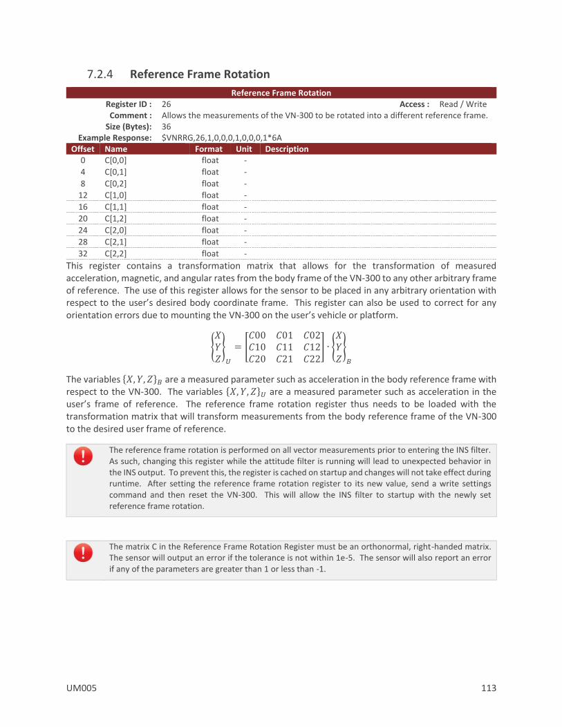
UM005 113
7.2.4 Reference Frame Rotation
Reference Frame Rotation Register ID : 26 Access : Read / Write Comment : Allows the measurements of the VN-300 to be rotated into a different reference frame.
Size (Bytes): 36 Example Response: $VNRRG,26,1,0,0,0,1,0,0,0,1*6A
Offset Name Format Unit Description 0 C[0,0] float -
4 C[0,1] float -
8 C[0,2] float -
12 C[1,0] float -
16 C[1,1] float -
20 C[1,2] float -
24 C[2,0] float -
28 C[2,1] float -
32 C[2,2] float -
This register contains a transformation matrix that allows for the transformation of measured acceleration, magnetic, and angular rates from the body frame of the VN-300 to any other arbitrary frame of reference. The use of this register allows for the sensor to be placed in any arbitrary orientation with respect to the user’s desired body coordinate frame. This register can also be used to correct for any orientation errors due to mounting the VN-300 on the user’s vehicle or platform.
𝑋𝑌𝑍
𝑈
= [𝐶00 𝐶01 𝐶02𝐶10 𝐶11 𝐶12𝐶20 𝐶21 𝐶22
] ∙ 𝑋𝑌𝑍
𝐵
The variables 𝑋, 𝑌, 𝑍𝐵 are a measured parameter such as acceleration in the body reference frame with respect to the VN-300. The variables 𝑋, 𝑌, 𝑍𝑈 are a measured parameter such as acceleration in the user’s frame of reference. The reference frame rotation register thus needs to be loaded with the transformation matrix that will transform measurements from the body reference frame of the VN-300 to the desired user frame of reference.
The reference frame rotation is performed on all vector measurements prior to entering the INS filter. As such, changing this register while the attitude filter is running will lead to unexpected behavior in the INS output. To prevent this, the register is cached on startup and changes will not take effect during runtime. After setting the reference frame rotation register to its new value, send a write settings command and then reset the VN-300. This will allow the INS filter to startup with the newly set reference frame rotation.
The matrix C in the Reference Frame Rotation Register must be an orthonormal, right-handed matrix. The sensor will output an error if the tolerance is not within 1e-5. The sensor will also report an error if any of the parameters are greater than 1 or less than -1.
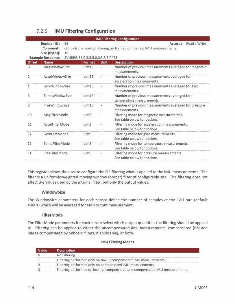
114 UM005
7.2.5 IMU Filtering Configuration
IMU Filtering Configuration Register ID : 85 Access : Read / Write Comment : Controls the level of filtering performed on the raw IMU measurements.
Size (Bytes): 15 Example Response: $VNRRG,85,0,5,5,5,0,0,3,3,3,0*78
Offset Name Format Unit Description 0 MagWindowSize uint16 - Number of previous measurements averaged for magnetic
measurements.
2 AccelWindowSize uint16 - Number of previous measurements averaged for acceleration measurements.
4 GyroWindowSize uint16 - Number of previous measurements averaged for gyro measurements.
6 TempWindowSize uint16 - Number of previous measurements averaged for temperature measurements.
8 PresWindowSize uint16 - Number of previous measurements averaged for pressure measurements.
10 MagFilterMode uint8 - Filtering mode for magnetic measurements. See table below for options.
11 AccelFilterMode uint8 - Filtering mode for acceleration measurements. See table below for options.
12 GyroFilterMode uint8 - Filtering mode for gyro measurements. See table below for options.
13 TempFilterMode uint8 - Filtering mode for temperature measurements. See table below for options.
14 PresFilterMode uint8 - Filtering mode for pressure measurements. See table below for options.
This register allows the user to configure the FIR filtering what is applied to the IMU measurements. The filter is a uniformly-weighted moving window (boxcar) filter of configurable size. The filtering does not affect the values used by the internal filter, but only the output values.
WindowSize
The WindowSize parameters for each sensor define the number of samples at the IMU rate (default 400Hz) which will be averaged for each output measurement.
FilterMode
The FilterMode parameters for each sensor select which output quantities the filtering should be applied to. Filtering can be applied to either the uncompensated IMU measurements, compensated (HSI and biases compensated by onboard filters, if applicable), or both.
IMU Filtering Modes
Value Description 0 No Filtering
1 Filtering performed only on raw uncompensated IMU measurements.
2 Filtering performed only on compensated IMU measurements.
3 Filtering performed on both uncompensated and compensated IMU measurements.

UM005 115
7.2.6 Delta Theta and Delta Velocity Configuration
Delta Theta and Delta Velocity Configuration Register ID : 82 Access : Read / Write Comment : This register contains configuration options for the internal coning/sculling calculations
Size (Bytes): 6 Example Response: $VNRRG,82,0,0,0,0,0*65
Offset Name Format Unit Description 0 IntegrationFrame uint8 - Output frame for delta velocity quantities
1 GyroCompensation uint8 - Compensation to apply to angular rate
2 AccelCompensation uint8 - Compensation(s) to apply to accelerations
3 Reserved uint8 - Reserved for future use. Should be set to 0.
4 Reserved uint16 - Reserved for future use. Should be set to 0.
The Delta Theta and Delta Velocity Configuration register allows configuration of the onboard coning and sculling used to generate integrated motion values from the angular rate and acceleration IMU quantities. The fully-coupled coning and sculling integrals are computed at the IMU sample rate (nominal 400 Hz).
IntegrationFrame
The IntegrationFrame register setting selects the reference frame used for coning and sculling. Note that using any frame other than the body frame will rely on the onboard Kalman filter’s attitude estimate. The factory default state is to integrate in the sensor body frame.
IntegrationFrame
Value Description 0 Body frame 1 NED frame 2 ECEF frame
GyroCompensation
The GyroCompensation register setting selects the compensation to be applied to the angular rate measurements before integration. If bias compensation is selected, the onboard Kalman filter’s real-time estimate of the gyro biases will be used to compensate the IMU measurements before integration. The factory default state is to integrate the uncompensated angular rates from the IMU.
GyroCompensation
Value Description 0 None 1 Bias
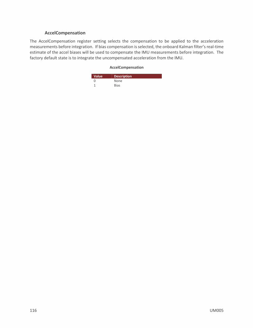
116 UM005
AccelCompensation
The AccelCompensation register setting selects the compensation to be applied to the acceleration measurements before integration. If bias compensation is selected, the onboard Kalman filter’s real-time estimate of the accel biases will be used to compensate the IMU measurements before integration. The factory default state is to integrate the uncompensated acceleration from the IMU.
AccelCompensation
Value Description 0 None 1 Bias

UM005 117
7.3 Factory Defaults Settings Name Default Factory Value Magnetometer Compensation 1,0,0,0,1,0,0,0,1,0,0,0
Accelerometer Compensation 1,0,0,0,1,0,0,0,1,0,0,0
Gyro Compensation 1,0,0,0,1,0,0,0,1,0,0,0
Reference Frame Rotation 1,0,0,0,1,0,0,0,1
IMU Filtering Configuration 0,4,4,4,0,0,3,3,3,0
Delta Theta and Delta Velocity Configuration
0,0,0,0,0

118 UM005
7.4 Command Prompt
The command prompt provides a fast and simple means of configuring and monitoring the status of the sensor by typing commands to the unit using the serial port.
7.4.1 List Available Commands
Commands for the System subsystem can be accessed by typing in ‘imu’ at the command prompt. To view all available commands, type ‘imu ?’. Below is a view of a terminal window showing a list of the available commands.
imu ?
Imu Module Commands:
Command: Description:
-------- --------------------------------------------------------------------
info Imu specific information such as serial number and firmware version.
meas Current Imu measurement, and run-time statistics.
7.4.2 IMU Info
imu info
------------------------------ Imu Information -------------------------------
Magnetometer - HSI Settings (Register 44)
Mode : Using Onboard
Magnetometer - User HSI Calibration (Register 23)
+01.000 +00.000 +00.000 +00.000
+00.000 +01.000 +00.000 +00.000
+00.000 +00.000 +01.000 +00.000
Magnetometer - Onboard HSI Calibration (Register 47)
+01.000 +00.000 +00.000 -00.000
+00.000 +01.000 +00.000 -00.000
+00.000 +00.000 +01.000 -00.000
Accelerometer - User Calibration (Register 25)
+01.000 +00.000 +00.000 +00.000
+00.000 +01.000 +00.000 +00.000
+00.000 +00.000 +01.000 +00.000
Sensor Self Test: (performed at startup)
Mag : Passed
Accel : Passed
Gyro : Passed
Pres : Passed
--------------------------------------------------------------------------------
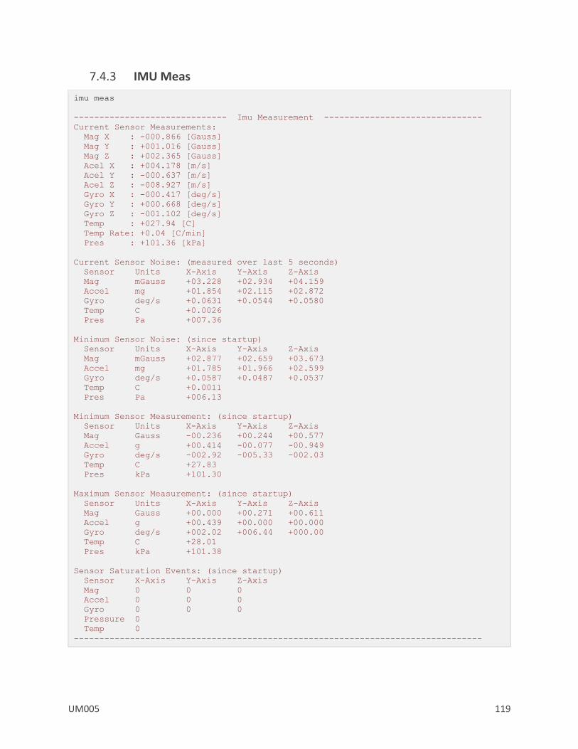
UM005 119
7.4.3 IMU Meas
imu meas
------------------------------ Imu Measurement -------------------------------
Current Sensor Measurements:
Mag X : -000.866 [Gauss]
Mag Y : +001.016 [Gauss]
Mag Z : +002.365 [Gauss]
Acel X : +004.178 [m/s]
Acel Y : -000.637 [m/s]
Acel Z : -008.927 [m/s]
Gyro X : -000.417 [deg/s]
Gyro Y : +000.668 [deg/s]
Gyro Z : -001.102 [deg/s]
Temp : +027.94 [C]
Temp Rate: +0.04 [C/min]
Pres : +101.36 [kPa]
Current Sensor Noise: (measured over last 5 seconds)
Sensor Units X-Axis Y-Axis Z-Axis
Mag mGauss +03.228 +02.934 +04.159
Accel mg +01.854 +02.115 +02.872
Gyro deg/s +0.0631 +0.0544 +0.0580
Temp C +0.0026
Pres Pa +007.36
Minimum Sensor Noise: (since startup)
Sensor Units X-Axis Y-Axis Z-Axis
Mag mGauss +02.877 +02.659 +03.673
Accel mg +01.785 +01.966 +02.599
Gyro deg/s +0.0587 +0.0487 +0.0537
Temp C +0.0011
Pres Pa +006.13
Minimum Sensor Measurement: (since startup)
Sensor Units X-Axis Y-Axis Z-Axis
Mag Gauss -00.236 +00.244 +00.577
Accel g +00.414 -00.077 -00.949
Gyro deg/s -002.92 -005.33 -002.03
Temp C +27.83
Pres kPa +101.30
Maximum Sensor Measurement: (since startup)
Sensor Units X-Axis Y-Axis Z-Axis
Mag Gauss +00.000 +00.271 +00.611
Accel g +00.439 +00.000 +00.000
Gyro deg/s +002.02 +006.44 +000.00
Temp C +28.01
Pres kPa +101.38
Sensor Saturation Events: (since startup)
Sensor X-Axis Y-Axis Z-Axis
Mag 0 0 0
Accel 0 0 0
Gyro 0 0 0
Pressure 0
Temp 0
--------------------------------------------------------------------------------
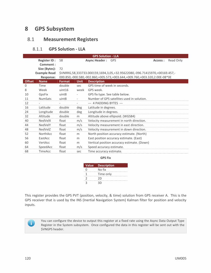
120 UM005
8 GPS Subsystem
8.1 Measurement Registers
8.1.1 GPS Solution - LLA
GPS Solution - LLA Register ID : 58 Async Header : GPS Access : Read Only Comment :
Size (Bytes): 72 Example Read
Response: $VNRRG,58,333733.000159,1694,3,05,+32.95622080,-096.71415970,+00169.457,-000.850,-000.580,-002.860,+005.573,+003.644,+009.760,+003.320,2.00E-08*0E
Offset Name Format Unit Description 0 Time double sec GPS time of week in seconds.
8 Week uint16 week GPS week.
10 GpsFix uint8 - GPS fix type. See table below.
11 NumSats uint8 - Number of GPS satellites used in solution.
12 - - - --- 4 PADDING BYTES ---
16 Latitude double deg Latitude in degrees.
24 Longitude double deg Longitude in degrees.
32 Altitude double m Altitude above ellipsoid. (WGS84)
40 NedVelX float m/s Velocity measurement in north direction.
44 NedVelY float m/s Velocity measurement in east direction.
48 NedVelZ float m/s Velocity measurement in down direction.
52 NorthAcc float m North position accuracy estimate. (North)
56 EastAcc float m East position accuracy estimate. (East)
60 VertAcc float m Vertical position accuracy estimate. (Down)
64 SpeedAcc float m/s Speed accuracy estimate.
68 TimeAcc float sec Time accuracy estimate.
GPS Fix
Value Description 0 No fix
1 Time only
2 2D
3 3D
This register provides the GPS PVT (position, velocity, & time) solution from GPS receiver A. This is the GPS receiver that is used by the INS (Inertial Navigation System) Kalman filter for position and velocity inputs.
You can configure the device to output this register at a fixed rate using the Async Data Output Type Register in the System subsystem. Once configured the data in this register will be sent out with the $VNGPS header.

UM005 121
8.1.2 GPS Solution - ECEF
GPS Solution – ECEF Register ID : 59 Async Header : GPE Access : Read Only Comment : Available at 5Hz only.
Size (Bytes): 72 Example Read
Response: $VNRRG,59,333752.800322,1694,3,06,-0626351.600,-5320522.490,+3449975.910,-000.810,-002.970,+000.850,+010.170,+010.170,+010.170,+002.740,1.80E-08*35
Offset Name Format Unit Description 0 Tow double sec GPS time of week.
8 Week uint16 week Current GPS week.
10 GpsFix uint8 - GPS fix type. See table below.
11 NumSats uint8 - Number of GPS satellites used in solution.
12 - - - --- 4 PADDING BYTES ---
16 PositionX double m ECEF X coordinate.
24 PositionY double m ECEF Y coordinate.
32 PositionZ double m ECEF Z coordinate.
40 VelocityX float m/s ECEF X velocity.
44 VelocityY float m/s ECEF Y velocity.
48 VelocityZ float m/s ECEF Z velocity.
52 PosAccX float m ECEF X position accuracy estimate.
56 PosAccY float m ECEF Y position accuracy estimate.
60 PosAccZ float m ECEF Z position accuracy estimate.
64 SpeedAcc float m/s Speed accuracy estimate.
68 TimeAcc float sec Time accuracy estimate.
GPS Fix
Value Description 0 No fix
1 Time only
2 2D
3 3D
This register provides the GPS PVT (position, velocity, & time) solution from GPS receiver A. This is the GPS receiver that is used by the INS (Inertial Navigation System) Kalman filter for position and velocity inputs.
You can configure the device to output this register at a fixed rate using the Async Data Output Type Register in the System subsystem. Once configured the data in this register will be sent out with the $VNGPE header.

122 UM005
8.1.3 GPS2 Solution - LLA
GPS2 Solution - LLA Register ID : 103 Async Header : G2S Access : Read Only Comment : The calculated navigation solution of the Ant B receiver, expressed in the LLA/NED frames.
Updates at the GPS rate (5Hz default). Size (Bytes): 72
Example Read Response:
$VNRRG,103,505020.999614,1941,3,13,+32.89195540,-096.70376740,+00165.491,+000.000,-000.008,-000.025,+001.320,+001.303,+003.259,+000.098,2.00E-09*35
Offset Name Format Unit Description 0 Time double sec GPS time of week in seconds.
8 Week uint16 week GPS week.
10 GpsFix uint8 - GPS fix type. See table below.
11 NumSats uint8 - Number of GPS satellites used in solution.
12 - - - --- 4 PADDING BYTES ---
16 Latitude double deg Latitude in degrees.
24 Longitude double deg Longitude in degrees.
32 Altitude double m Altitude above ellipsoid. (WGS84)
40 NedVelX float m/s Velocity measurement in north direction.
44 NedVelY float m/s Velocity measurement in east direction.
48 NedVelZ float m/s Velocity measurement in down direction.
52 NorthAcc float m North position accuracy estimate. (North)
56 EastAcc float m East position accuracy estimate. (East)
60 VertAcc float m Vertical position accuracy estimate. (Down)
64 SpeedAcc float m/s Speed accuracy estimate.
68 TimeAcc float sec Time accuracy estimate.
GPS Fix
Value Description 0 No fix
1 Time only
2 2D
3 3D
You can configure the device to output this register at a fixed rate using the Async Data Output Type Register in the System subsystem. Once configured, the data in this register will be sent out with the $VNG2S header.
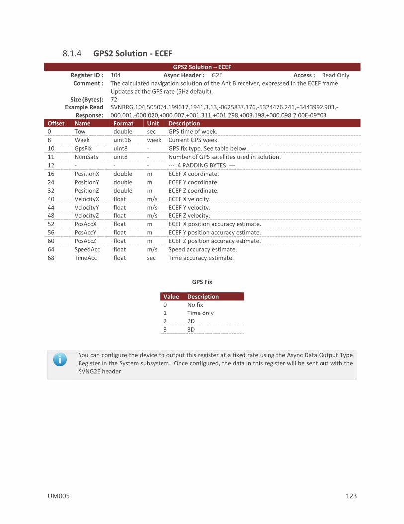
UM005 123
8.1.4 GPS2 Solution - ECEF
GPS2 Solution – ECEF Register ID : 104 Async Header : G2E Access : Read Only Comment : The calculated navigation solution of the Ant B receiver, expressed in the ECEF frame.
Updates at the GPS rate (5Hz default). Size (Bytes): 72
Example Read Response:
$VNRRG,104,505024.199617,1941,3,13,-0625837.176,-5324476.241,+3443992.903,-000.001,-000.020,+000.007,+001.311,+001.298,+003.198,+000.098,2.00E-09*03
Offset Name Format Unit Description 0 Tow double sec GPS time of week.
8 Week uint16 week Current GPS week.
10 GpsFix uint8 - GPS fix type. See table below.
11 NumSats uint8 - Number of GPS satellites used in solution.
12 - - - --- 4 PADDING BYTES ---
16 PositionX double m ECEF X coordinate.
24 PositionY double m ECEF Y coordinate.
32 PositionZ double m ECEF Z coordinate.
40 VelocityX float m/s ECEF X velocity.
44 VelocityY float m/s ECEF Y velocity.
48 VelocityZ float m/s ECEF Z velocity.
52 PosAccX float m ECEF X position accuracy estimate.
56 PosAccY float m ECEF Y position accuracy estimate.
60 PosAccZ float m ECEF Z position accuracy estimate.
64 SpeedAcc float m/s Speed accuracy estimate.
68 TimeAcc float sec Time accuracy estimate.
GPS Fix
Value Description 0 No fix
1 Time only
2 2D
3 3D
You can configure the device to output this register at a fixed rate using the Async Data Output Type Register in the System subsystem. Once configured, the data in this register will be sent out with the $VNG2E header.

124 UM005
8.2 Configuration Registers
8.2.1 GPS Configuration
GPS Configuration Register ID : 55 Access : Read / Write Comment :
Size (Bytes): 5 Example Response: $VNRRG,55,0,0,5,0,1*6B
Offset Name Format Unit Description 0 Mode uint8 - GPS mode.
0 = Use onboard GPS. 1 = Use external GPS. 2 = Use external VectorNav sensor as the GPS.
1 PpsSource uint8 - GPS PPS mode. 0 = GPS PPS signal is present on the GPS_PPS pin (pin 24) and should trigger on a rising edge. 1 = GPS PPS signal is present on the GPS_PPS pin (pin 24) and should trigger on a falling edge. 2 = GPS PPS signal is present on the SyncIn pin (pin 22) and should trigger on a rising edge. 3 = GPS PPS signal is present on the SyncIn pin (pin 22) and should trigger on a falling edge.
2 Rate uint8 - GPS navigation rate. Value must be set to 5.
3 TimeSyncDelta uint8 - Reserved for future use. Field should be set to zero.
4 AntPower uint8 - Antenna supply configuration. Values other than 1 are only supported on the VN300-SMD. 0 = Disable antenna power supply. 1 = Use internal antenna power supply (3V, 50mA combined). 2 = Use external antenna power supply (VANT pin, up to 5V and 100mA combined).

UM005 125
8.2.2 GPS Antenna A Offset
GPS Antenna A Offset Register ID : 57 Access : Read / Write
Comment : Configures the position offset of GPS antenna A from the VN-300 in the vehicle reference frame.
Size (Bytes): 12 Example Response: $VNRRG,57,0,0,0*68
Offset Name Format Unit Description 0 PositionX float m Relative position of GPS antenna. (X-axis)
4 PositionY float m Relative position of GPS antenna. (Y-axis)
8 PositionZ float m Relative position of GPS antenna. (Z-axis)
The position of the GPS antenna A relative to the sensor in the vehicle coordinate frame also referred to as the GPS antenna lever arm. In the example scenario shown in the figure below, the GPS antenna offset is X= +2.5m, Y= +0.0m, Z= -2.0m.
GPS Antenna A Offset
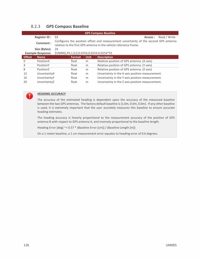
126 UM005
8.2.3 GPS Compass Baseline
GPS Compass Baseline Register ID : 93 Access : Read / Write
Comment : Configures the position offset and measurement uncertainty of the second GPS antenna relative to the first GPS antenna in the vehicle reference frame.
Size (Bytes): 24 Example Response: $VNRRG,93,1,0,0,0.0254,0.0254,0.0254*55
Offset Name Format Unit Description 0 PositionX float m Relative position of GPS antenna. (X-axis)
4 PositionY float m Relative position of GPS antenna. (Y-axis)
8 PositionZ float m Relative position of GPS antenna. (Z-axis)
12 UncertaintyX float m Uncertainty in the X-axis position measurement.
16 UncertaintyY float m Uncertainty in the Y-axis position measurement.
20 UncertaintyZ float m Uncertainty in the Z-axis position measurement.
HEADING ACCURACY
The accuracy of the estimated heading is dependent upon the accuracy of the measured baseline between the two GPS antennas. The factory default baseline is 1.0m, 0.0m, 0.0m. If any other baseline is used, it is extremely important that the user acurately measures this baseline to ensure accurate heading estimates.
The heading accuracy is linearly proportional to the measurement accuracy of the position of GPS antenna B with respect to GPS antenna A, and inversely proportional to the baseline length.
Heading Error [deg] ~= 0.57 * (Baseline Error [cm]) / (Baseline Length [m])
On a 1 meter baseline, a 1 cm measurement error equates to heading error of 0.6 degrees.
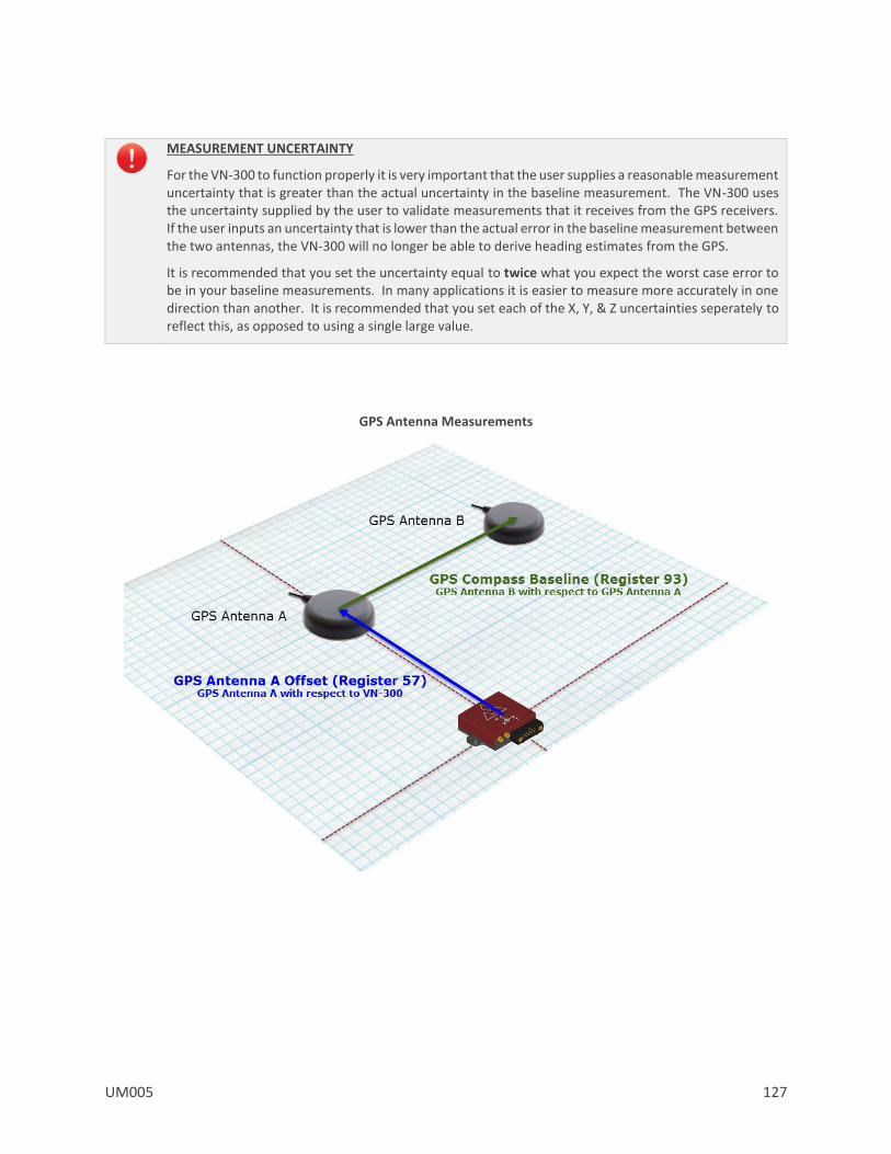
UM005 127
MEASUREMENT UNCERTAINTY
For the VN-300 to function properly it is very important that the user supplies a reasonable measurement uncertainty that is greater than the actual uncertainty in the baseline measurement. The VN-300 uses the uncertainty supplied by the user to validate measurements that it receives from the GPS receivers. If the user inputs an uncertainty that is lower than the actual error in the baseline measurement between the two antennas, the VN-300 will no longer be able to derive heading estimates from the GPS.
It is recommended that you set the uncertainty equal to twice what you expect the worst case error to be in your baseline measurements. In many applications it is easier to measure more accurately in one direction than another. It is recommended that you set each of the X, Y, & Z uncertainties seperately to reflect this, as opposed to using a single large value.
GPS Antenna Measurements

128 UM005
8.3 Status Registers
8.3.1 GPS Compass Startup Status
GPS Compass Startup Status Register ID : 98 Access : Read Comment : Provides status information on the GPS compass startup process.
Size (Bytes): 8 Example Response: $VNRRG,98,046,+001.318*4E
Offset Name Format Unit Description 0 PercentComplete uint8 - The estimated startup process completion percent
4 CurrentHeading float deg The current best heading estimate
The percentage may decrease if the satellites signal integrity is compromised during the startup process.
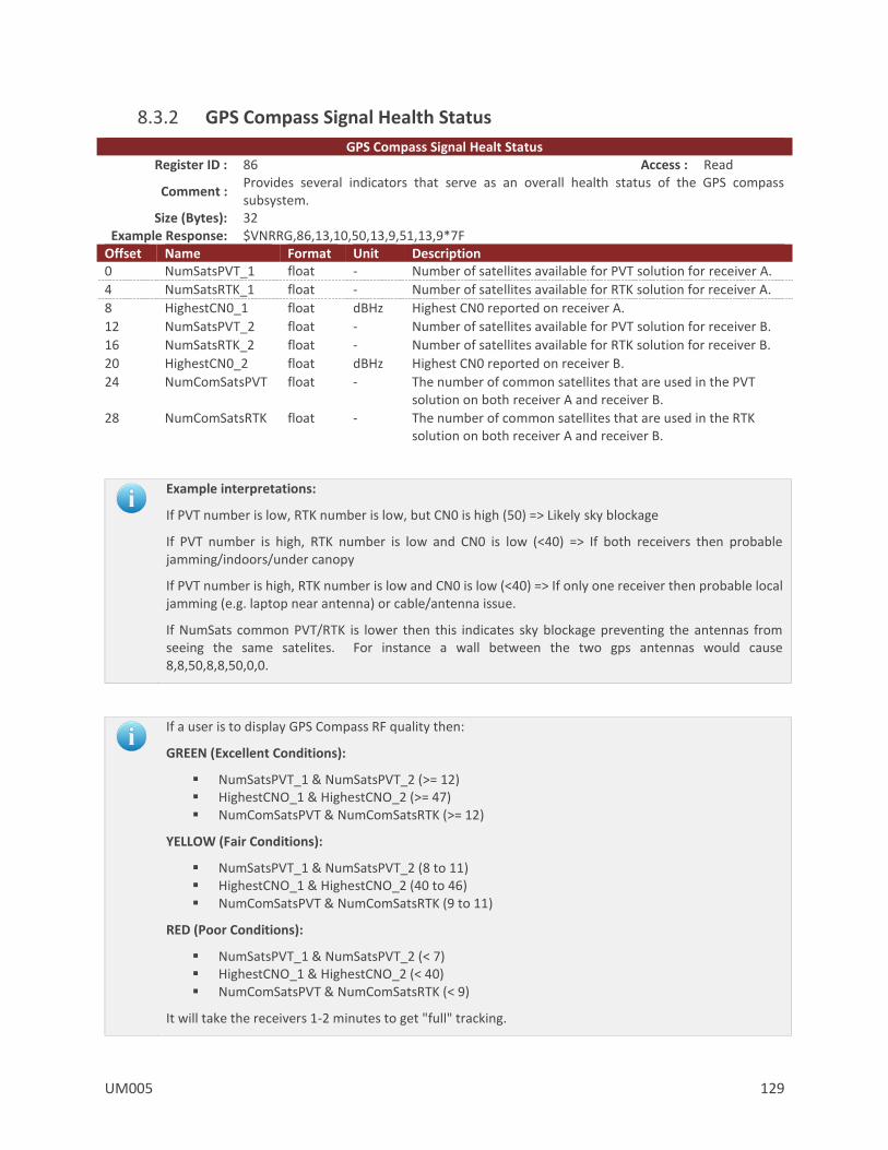
UM005 129
8.3.2 GPS Compass Signal Health Status
GPS Compass Signal Healt Status Register ID : 86 Access : Read
Comment : Provides several indicators that serve as an overall health status of the GPS compass subsystem.
Size (Bytes): 32 Example Response: $VNRRG,86,13,10,50,13,9,51,13,9*7F
Offset Name Format Unit Description 0 NumSatsPVT_1 float - Number of satellites available for PVT solution for receiver A.
4 NumSatsRTK_1 float - Number of satellites available for RTK solution for receiver A.
8 HighestCN0_1 float dBHz Highest CN0 reported on receiver A.
12 NumSatsPVT_2 float - Number of satellites available for PVT solution for receiver B.
16 NumSatsRTK_2 float - Number of satellites available for RTK solution for receiver B.
20 HighestCN0_2 float dBHz Highest CN0 reported on receiver B.
24 NumComSatsPVT float - The number of common satellites that are used in the PVT solution on both receiver A and receiver B.
28 NumComSatsRTK float - The number of common satellites that are used in the RTK solution on both receiver A and receiver B.
Example interpretations:
If PVT number is low, RTK number is low, but CN0 is high (50) => Likely sky blockage
If PVT number is high, RTK number is low and CN0 is low (<40) => If both receivers then probable jamming/indoors/under canopy
If PVT number is high, RTK number is low and CN0 is low (<40) => If only one receiver then probable local jamming (e.g. laptop near antenna) or cable/antenna issue.
If NumSats common PVT/RTK is lower then this indicates sky blockage preventing the antennas from seeing the same satelites. For instance a wall between the two gps antennas would cause 8,8,50,8,8,50,0,0.
If a user is to display GPS Compass RF quality then:
GREEN (Excellent Conditions):
NumSatsPVT_1 & NumSatsPVT_2 (>= 12) HighestCNO_1 & HighestCNO_2 (>= 47) NumComSatsPVT & NumComSatsRTK (>= 12)
YELLOW (Fair Conditions):
NumSatsPVT_1 & NumSatsPVT_2 (8 to 11) HighestCNO_1 & HighestCNO_2 (40 to 46) NumComSatsPVT & NumComSatsRTK (9 to 11)
RED (Poor Conditions):
NumSatsPVT_1 & NumSatsPVT_2 (< 7) HighestCNO_1 & HighestCNO_2 (< 40) NumComSatsPVT & NumComSatsRTK (< 9)
It will take the receivers 1-2 minutes to get "full" tracking.

130 UM005
8.4 NMEA Messages
8.4.1 RMC – Recommended Minumum Sentence C
Example:
$GPRMC,193144.00,A,3253.508483,N,09642.202932,W,0.015,242.35,260116,3.44,E,D,V*51
Field Structure Format Units Example 1 RMC Header $GPRMC n/a
2 Time hhmmss.ss 193144.00 3 Status A A – Data valid
V – Data invalid A
4,5 Latitude, N/S ddmm.mm,a Degrees minutes, Direction indicator
3253.508483,N
6,7 Longitude, E/W ddmm.mm,a Degrees minutes, Direction indicator
09642.202932,W
8 Speed over ground x.xx knots 0.015
9 Course over ground x.xx degrees True 242.35
10 Date ddmmyy 260116
11,12 Magnetic variation, E/W x.xx,a Degrees minutes, Direction indicator
3.44,E
13 Mode Indicator a D
14 Navigational Status a V 15 Sentence terminator *XX<CRLF> Checksum *51<CRLF>

UM005 131
8.4.2 GGA – Global Positioning System Fix Data
Example:
$GPGGA,193144.00,3253.508483,N,09642.202932,W,2,10,0.83,185.976,M,-25.278,M,,0000*6A
Field Structure Format Units Example 1 GGA header $GPGGA n/a 2 Time hhmss.ss 193144.00
3, 4 Latitude, N/S ddmm.mm,a Degrees minutes, Direction Indicator
3253.508483,N
5, 6 Longitude, E/W dddmm.mm,a Degrees minutes, Direction Indicator
09642.202932,W
7 Quality Indicator a 0 - Fix invalid 1 - GPS SPS mode, fix valid 2 - Differential GPS, SPS mode, fix valid 6 - Estimated (dead reckoning) Mode
2
8 Number of satellites used dd 00-12 10
9 Horizontal dilution of precision x.xx 0.83
10, 11 Altitude, mean-sea-level, in meters
x.xx,a Meters 185.976,M
12,13 Geoidal separation x.xx,a Meters -25.278,M
14 Age of data a Not populated
15 Differential reference station ID xxxx Always “0000”
16 Sentence terminator *XX<CRLF> Checksum *6A<CRLF>

132 UM005
8.4.3 GLL – Geographic Position
Example:
$GPGLL,3253.508483,N,09642.202932,W,193144.00,A,D*70
Field Structure Format Units Example 1 GLL header $GPGLL n/a 2,3 Latitude, N/S ddmm.mm,a Degrees minutes,
Direction Indicator 3253.508483,N
4,5 Longitude, E/W dddmm.mm,a Degrees minutes, Direction Indicator
09642.202932,W
6 Time hhmmss.ss 193144.00
7 Status a V = Invalid A = Autonomous D = Differential
A
8 Mode a A = Autonomous D = Differential E = Estimated N = Data invalid
D
9 Sentence terminator *XX<CRLF> Checksum *70<CRLF>
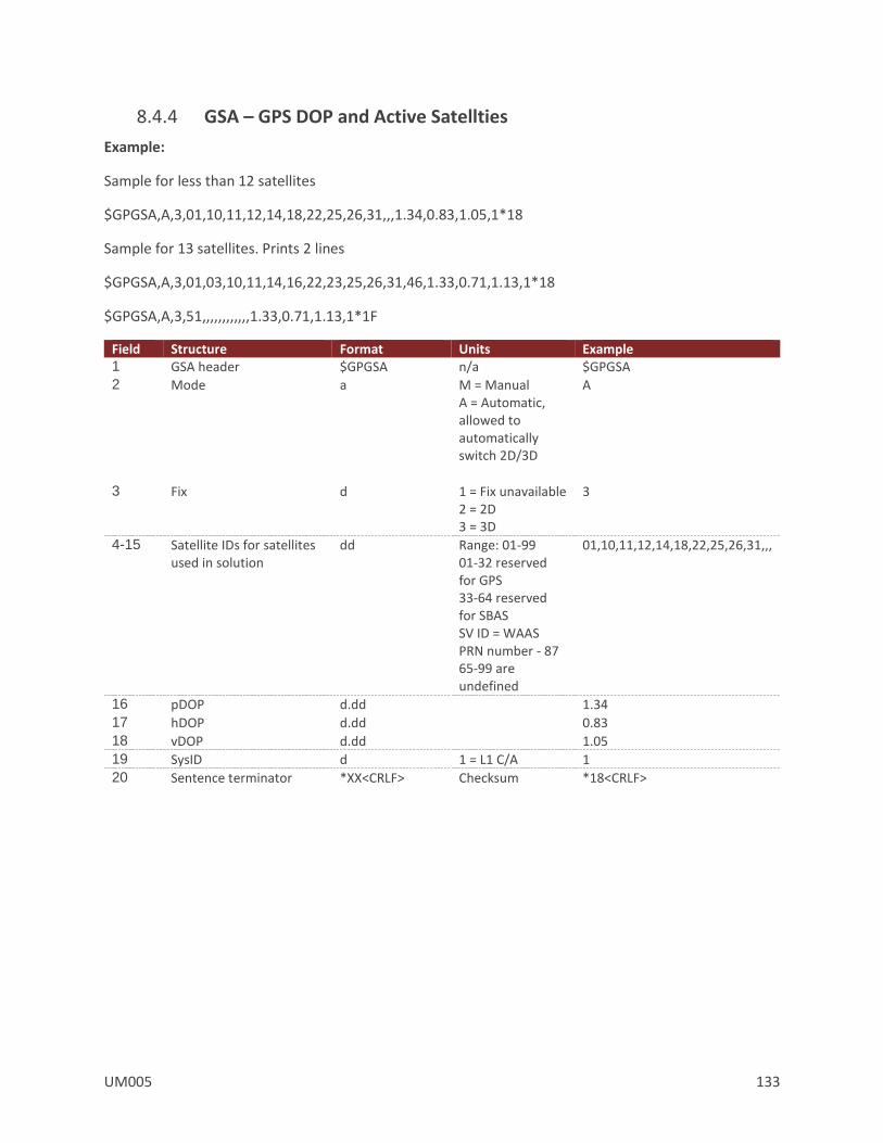
UM005 133
8.4.4 GSA – GPS DOP and Active Satellties
Example:
Sample for less than 12 satellites
$GPGSA,A,3,01,10,11,12,14,18,22,25,26,31,,,1.34,0.83,1.05,1*18
Sample for 13 satellites. Prints 2 lines
$GPGSA,A,3,01,03,10,11,14,16,22,23,25,26,31,46,1.33,0.71,1.13,1*18
$GPGSA,A,3,51,,,,,,,,,,,,1.33,0.71,1.13,1*1F
Field Structure Format Units Example 1 GSA header $GPGSA n/a $GPGSA 2 Mode a M = Manual
A = Automatic, allowed to automatically switch 2D/3D
A
3 Fix d 1 = Fix unavailable 2 = 2D 3 = 3D
3
4-15 Satellite IDs for satellites used in solution
dd
Range: 01-99 01-32 reserved for GPS 33-64 reserved for SBAS SV ID = WAAS PRN number - 87 65-99 are undefined
01,10,11,12,14,18,22,25,26,31,,,
16 pDOP d.dd 1.34
17 hDOP d.dd 0.83
18 vDOP d.dd 1.05
19 SysID d 1 = L1 C/A 1
20 Sentence terminator *XX<CRLF> Checksum *18<CRLF>

134 UM005
8.4.5 GSV – GPS Satellties in View
Example:
Sample with 14 satellites in view
$GPGSV,4,1,14,01,26,305,45,03,02,311,37,10,49,119,48,11,21,282,44,1*62
$GPGSV,4,2,14,12,08,043,36,14,53,033,49,18,17,126,41,22,83,005,47,1*62
$GPGSV,4,3,14,25,26,078,48,26,08,171,43,31,72,199,49,32,38,316,,1*6F
$GPGSV,4,4,14,46,50,182,45,51,50,199,45,1*6D
Field Structure Format Units Example 1 GSV header $GPGSV n/a $GPGSV 2 Total number of
sentences d
n/a Range: 1 to 9
4
3 Sentence number d n/a Range: 1 to 9
1
4 Total number of satellites in view
d
n/a 14
5 Satellite ID number dd 01
6 Elevation dd degrees Range: 00 to 90
26
7 Azimuth ddd degrees True Range: 000 to 359
305
8 SNR (C/No) dd dB-Hz Range: 00 to 99
45
9-12 2nd SatID,El,Az,SNR dd,dd,ddd,dd 03,02,311,37
13-16 3rd SatID,El,Az,SNR dd,dd,ddd,dd 10,49,119,48
17-20 4th SatID,El,Az,SNR dd,dd,ddd,dd 11,21,282,44
21 Signal ID x 1= L1 C/A 1
22 Sentence terminator *XX<CRLF> Checksum *62<CRLF>
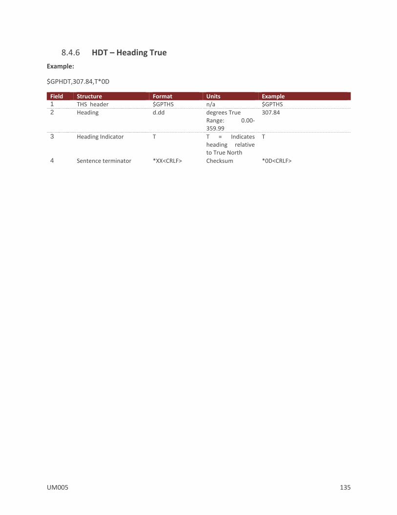
UM005 135
8.4.6 HDT – Heading True
Example:
$GPHDT,307.84,T*0D
Field Structure Format Units Example 1 THS header $GPTHS n/a $GPTHS 2 Heading d.dd
degrees True Range: 0.00-359.99
307.84
3 Heading Indicator T T = Indicates heading relative to True North
T
4 Sentence terminator *XX<CRLF> Checksum *0D<CRLF>
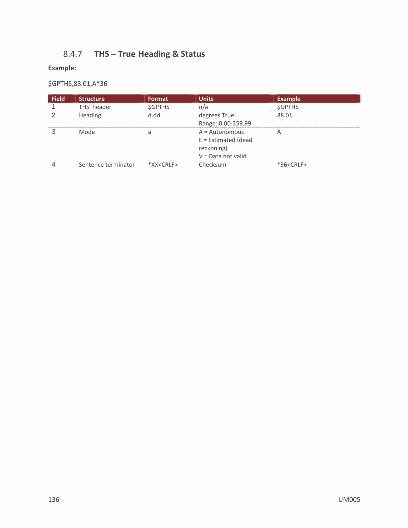
136 UM005
8.4.7 THS – True Heading & Status
Example:
$GPTHS,88.01,A*36
Field Structure Format Units Example 1 THS header $GPTHS n/a $GPTHS 2 Heading d.dd
degrees True Range: 0.00-359.99
88.01
3 Mode a A = Autonomous E = Estimated (dead reckoning) V = Data not valid
A
4 Sentence terminator *XX<CRLF> Checksum *36<CRLF>

UM005 137
8.4.8 VTG – Course Over Ground And Ground Speed
Example:
$GPVTG,242.35,T,238.91,M,0.015,N,0.028,K,D*2B
Field Structure Format Units Example 1 VTG header $GPVTG n/a $GPVTG 2,3 Course over ground d.dd,T
degrees True Range: 0.00-359.99
242.35,T
4,5 Course over ground d.dd,M degrees Magnetic Range: 0.00-359.99
238.91,M
6,7 Speed over ground d.ddd,N knots 0.015,N

138 UM005
8.4.9 ZDA – UTC Time & Date
Example:
$GPZDA,193144.00,26,01,2016,00,00*6C
Field Structure Format Units Example 1 ZDA header $xxZDA n/a $GPZDA 2 UTC Time hhmmss.ss 193144.00
3 UTC Day dd Range: 01-31 26
4 UTC Month dd Range: 01-12 01
5 UTC Year dddd 2016
6 Local Zone hours dd Always “00” 00
7 Local Zone minutes dd Always “00” 00
8 Sentence terminator *XX<CRLF> Checksum *6C<CRLF>
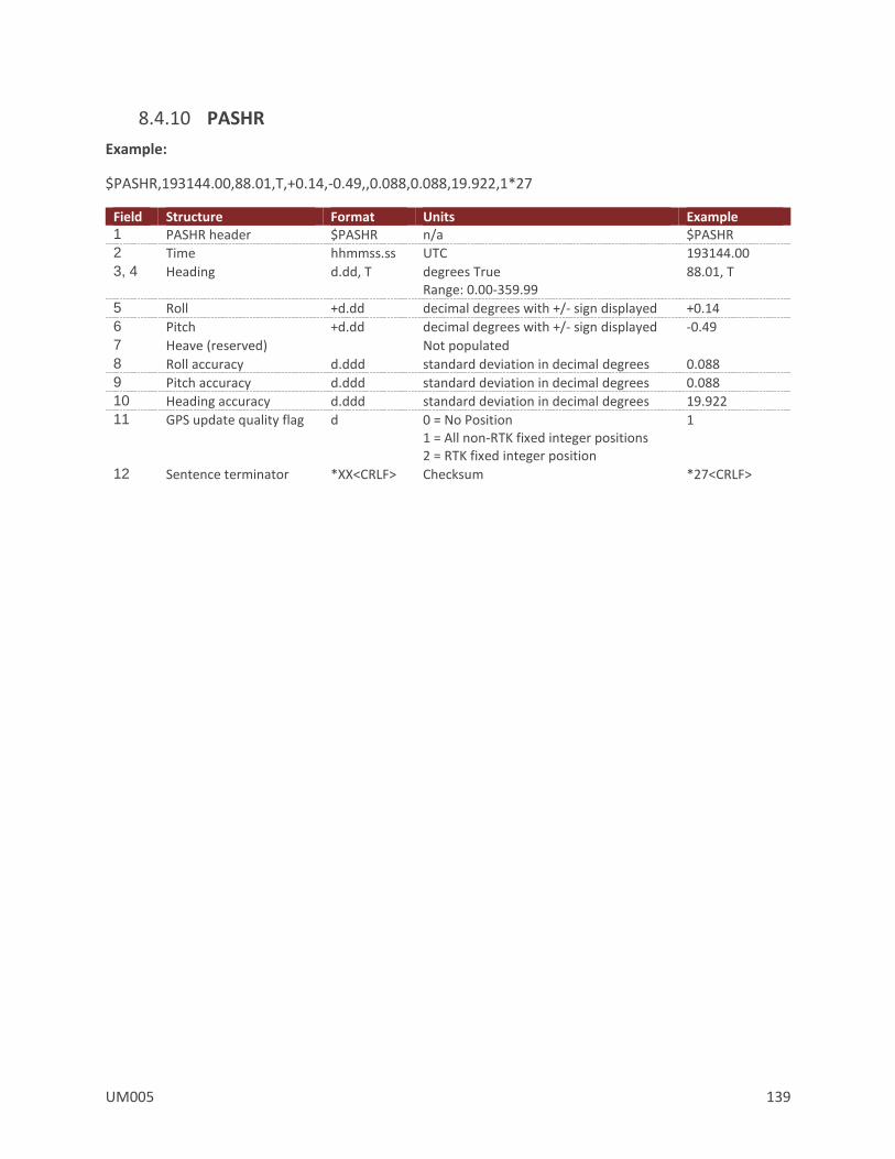
UM005 139
8.4.10 PASHR
Example:
$PASHR,193144.00,88.01,T,+0.14,-0.49,,0.088,0.088,19.922,1*27
Field Structure Format Units Example 1 PASHR header $PASHR n/a $PASHR 2 Time hhmmss.ss UTC 193144.00
3, 4 Heading d.dd, T
degrees True Range: 0.00-359.99
88.01, T
5 Roll +d.dd decimal degrees with +/- sign displayed +0.14
6 Pitch +d.dd decimal degrees with +/- sign displayed -0.49
7 Heave (reserved) Not populated
8 Roll accuracy d.ddd standard deviation in decimal degrees 0.088
9 Pitch accuracy d.ddd standard deviation in decimal degrees 0.088 10 Heading accuracy d.ddd standard deviation in decimal degrees 19.922
11 GPS update quality flag d 0 = No Position 1 = All non-RTK fixed integer positions 2 = RTK fixed integer position
1
12 Sentence terminator *XX<CRLF> Checksum *27<CRLF>

140 UM005
8.4.11 TSS1
Example:
Fixed length of 27 characters
Sample: :00FFFF 0000F 0014 -0048
Field Structure Format Units Example 1 Start of packet ASCII (0x3A) n/a :
2 Horizontal acceleration xx 0.03835 m/ss Range: 0-9.81
00
3 Vertical acceleration xxxx
0.000625 m/ss Range:-20.48 to 20.48
FFFF
4 Space character ASCII (0x20)
5 Heave (Reserved)
mdddd centimeters Not supported Always “ 0000”
“ 0000”
6 Status flag a h - Heading aided mode but unstable data F - Full aided mode and stable data
F
7 Roll angle mdddd 1 char for sign “ “ if positive “-” if negative 4 char decimal number
0.01° Range: -90° to +90°
“ 0014”
8 Space character ASCII (0x20)
9 Pitch angle mdddd 1 char for sign “ “ if positive “-” if negative 4 char decimal number
0.01° Range: -90° to +90°
“-0048”
10 Sentence terminator <CRLF> <CRLF>

UM005 141
8.5 Factory Defaults Settings Name Default Factory Value Gps Configuration 0,0,5,0,1
GPS Antenna A Offset 0,0,0
GPS Compass Baseline 1,0,0,0.0254,0.0254,0.0254
GPS Compass Estimated Baseline 0,0,0,0,0,0,0,0,0
GPS Compass Baseline Config 1,0,0,0.0254,0.0254,0.0254
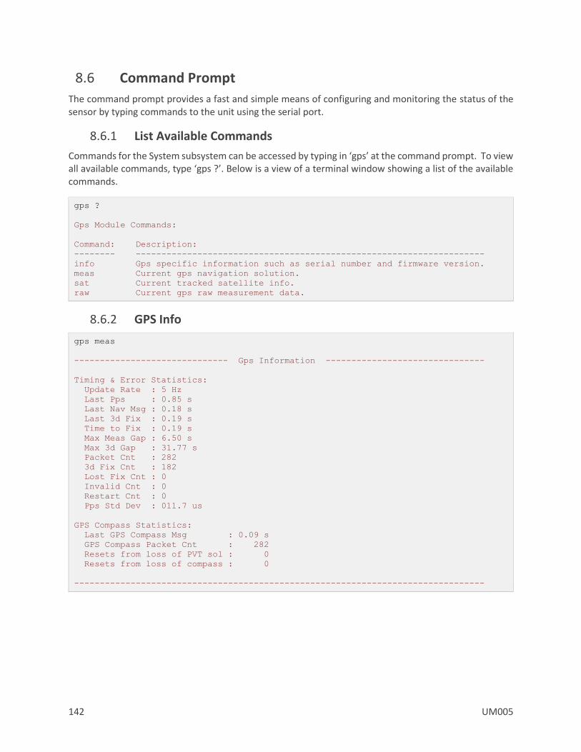
142 UM005
8.6 Command Prompt
The command prompt provides a fast and simple means of configuring and monitoring the status of the sensor by typing commands to the unit using the serial port.
8.6.1 List Available Commands
Commands for the System subsystem can be accessed by typing in ‘gps’ at the command prompt. To view all available commands, type ‘gps ?’. Below is a view of a terminal window showing a list of the available commands.
gps ?
Gps Module Commands:
Command: Description:
-------- --------------------------------------------------------------------
info Gps specific information such as serial number and firmware version.
meas Current gps navigation solution.
sat Current tracked satellite info.
raw Current gps raw measurement data.
8.6.2 GPS Info
gps meas
------------------------------ Gps Information -------------------------------
Timing & Error Statistics:
Update Rate : 5 Hz
Last Pps : 0.85 s
Last Nav Msg : 0.18 s
Last 3d Fix : 0.19 s
Time to Fix : 0.19 s
Max Meas Gap : 6.50 s
Max 3d Gap : 31.77 s
Packet Cnt : 282
3d Fix Cnt : 182
Lost Fix Cnt : 0
Invalid Cnt : 0
Restart Cnt : 0
Pps Std Dev : 011.7 us
GPS Compass Statistics:
Last GPS Compass Msg : 0.09 s
GPS Compass Packet Cnt : 282
Resets from loss of PVT sol : 0
Resets from loss of compass : 0
--------------------------------------------------------------------------------
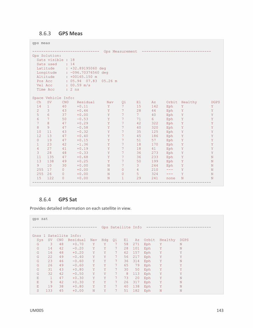
UM005 143
8.6.3 GPS Meas
gps meas
------------------------------ Gps Measurement -------------------------------
Gps Solution:
Sats visible : 18
Sats used : 14
Latitude : +32.89195060 deg
Longitude : -096.70376560 deg
Altitude : +00165.150 m
Pos Acc : 05.94 07.83 05.26 m
Vel Acc : 00.59 m/s
Time Acc : 2 ns
Space Vehicle Info:
Ch SV CN0 Residual Nav Qi El Az Orbit Healthy DGPS
14 1 40 +0.11 Y 7 15 142 Eph Y Y
2 3 43 +0.46 Y 7 28 44 Eph Y Y
5 6 37 +0.00 Y 7 7 40 Eph Y Y
6 7 50 -0.53 Y 7 71 6 Eph Y Y
7 8 47 +0.29 Y 7 42 322 Eph Y Y
8 9 47 -0.58 Y 7 40 320 Eph Y Y
10 11 43 -0.32 Y 7 35 125 Eph Y Y
12 13 47 +0.40 Y 7 45 186 Eph Y Y
0 19 47 +0.15 Y 7 51 57 Eph Y Y
1 23 42 -1.36 Y 7 18 170 Eph Y Y
4 27 41 +0.19 Y 7 18 41 Eph Y Y
3 28 48 -0.33 Y 7 36 273 Eph Y Y
11 135 47 +0.68 Y 7 36 233 Eph Y N
13 138 49 +0.25 Y 7 50 199 Eph Y N
9 10 30 +0.00 N 7 3 244 Eph Y N
255 17 0 +0.00 N 0 4 210 --- Y N
255 26 0 +0.00 N 0 5 324 --- Y N
15 122 0 +0.00 N 1 29 241 none N N
--------------------------------------------------------------------------------
8.6.4 GPS Sat
Provides detailed information on each satellite in view.
gps sat
----------------------------- Gps Satellite Info -----------------------------
Gnss 1 Satellite Info:
Sys SV CN0 Residual Nav Hdg Qi El Az Orbit Healthy DGPS
G 3 48 +0.70 Y Y 7 58 271 Eph Y N
G 14 42 -0.20 Y Y 7 28 101 Eph Y N
G 16 48 +0.20 Y Y 7 62 157 Eph Y Y
G 22 49 -0.40 Y Y 7 56 217 Eph Y Y
G 23 46 -0.60 Y Y 7 36 314 Eph Y N
G 26 49 -0.60 Y Y 7 65 79 Eph Y Y
G 31 43 +0.80 Y Y 7 30 50 Eph Y Y
G 32 42 -0.50 Y Y 7 8 113 Eph Y Y
E 1 47 +0.30 Y Y 7 73 20 Eph Y N
E 9 42 +0.30 Y Y 7 26 317 Eph Y N
E 19 38 +0.80 Y Y 7 40 138 Eph Y N
S 133 45 +0.00 N Y 7 51 182 Eph N N
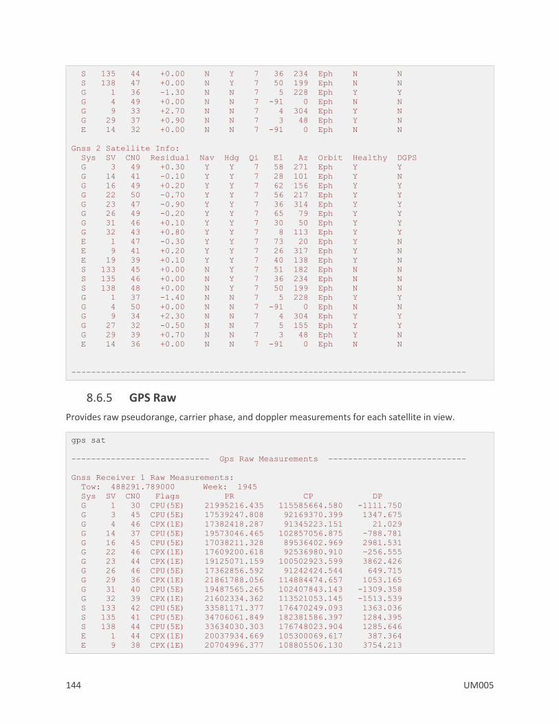
144 UM005
S 135 44 +0.00 N Y 7 36 234 Eph N N
S 138 47 +0.00 N Y 7 50 199 Eph N N
G 1 36 -1.30 N N 7 5 228 Eph Y Y
G 4 49 +0.00 N N 7 -91 0 Eph N N
G 9 33 +2.70 N N 7 4 304 Eph Y N
G 29 37 +0.90 N N 7 3 48 Eph Y N
E 14 32 +0.00 N N 7 -91 0 Eph N N
Gnss 2 Satellite Info:
Sys SV CN0 Residual Nav Hdg Qi El Az Orbit Healthy DGPS
G 3 49 +0.30 Y Y 7 58 271 Eph Y Y
G 14 41 -0.10 Y Y 7 28 101 Eph Y N
G 16 49 +0.20 Y Y 7 62 156 Eph Y Y
G 22 50 -0.70 Y Y 7 56 217 Eph Y Y
G 23 47 -0.90 Y Y 7 36 314 Eph Y Y
G 26 49 -0.20 Y Y 7 65 79 Eph Y Y
G 31 46 +0.10 Y Y 7 30 50 Eph Y Y
G 32 43 +0.80 Y Y 7 8 113 Eph Y Y
E 1 47 -0.30 Y Y 7 73 20 Eph Y N
E 9 41 +0.20 Y Y 7 26 317 Eph Y N
E 19 39 +0.10 Y Y 7 40 138 Eph Y N
S 133 45 +0.00 N Y 7 51 182 Eph N N
S 135 46 +0.00 N Y 7 36 234 Eph N N
S 138 48 +0.00 N Y 7 50 199 Eph N N
G 1 37 -1.40 N N 7 5 228 Eph Y Y
G 4 50 +0.00 N N 7 -91 0 Eph N N
G 9 34 +2.30 N N 7 4 304 Eph Y Y
G 27 32 -0.50 N N 7 5 155 Eph Y Y
G 29 39 +0.70 N N 7 3 48 Eph Y N
E 14 36 +0.00 N N 7 -91 0 Eph N N
--------------------------------------------------------------------------------
8.6.5 GPS Raw
Provides raw pseudorange, carrier phase, and doppler measurements for each satellite in view.
gps sat
---------------------------- Gps Raw Measurements ----------------------------
Gnss Receiver 1 Raw Measurements:
Tow: 488291.789000 Week: 1945
Sys SV CN0 Flags PR CP DP
G 1 30 CPU(5E) 21995216.435 115585664.580 -1111.750
G 3 45 CPU(5E) 17539247.808 92169370.399 1347.675
G 4 46 CPX(1E) 17382418.287 91345223.151 21.029
G 14 37 CPU(5E) 19573046.465 102857056.875 -788.781
G 16 45 CPU(5E) 17038211.328 89536402.969 2981.531
G 22 46 CPX(1E) 17609200.618 92536980.910 -256.555
G 23 44 CPX(1E) 19125071.159 100502923.599 3862.426
G 26 46 CPU(5E) 17362856.592 91242424.544 649.715
G 29 36 CPX(1E) 21861788.056 114884474.657 1053.165
G 31 40 CPU(5E) 19487565.265 102407843.143 -1309.358
G 32 39 CPX(1E) 21602334.362 113521053.145 -1513.539
S 133 42 CPU(5E) 33581171.377 176470249.093 1363.036
S 135 41 CPU(5E) 34706061.849 182381586.397 1284.395
S 138 44 CPU(5E) 33634030.303 176748023.904 1285.646
E 1 44 CPX(1E) 20037934.669 105300069.617 387.364
E 9 38 CPX(1E) 20704996.377 108805506.130 3754.213

UM005 145
E 14 31 CPX(1E) 22905458.870 120369000.152 5929.075
E 19 35 CPX(1E) 21708714.613 114080079.734 -864.291
Gnss Receiver 2 Raw Measurements:
Tow: 488291.796000 Week: 1945
Sys SV CN0 Flags PR CP DP
G 1 33 CPU(5E) 24143253.395 126873636.789 -1942.844
G 3 46 CPX(1E) 19687282.117 103457364.551 517.010
G 4 47 CPX(1E) 19530453.118 102633220.531 -809.564
G 9 29 CPU(5E) 23883872.888 125510648.972 3475.966
G 14 37 CPU(5E) 21721080.948 114145048.940 -1619.466
G 16 46 CPU(5E) 19186245.410 100824400.286 2150.645
G 22 46 CPX(1E) 19757234.490 103824970.459 -1087.305
G 23 44 CPX(1E) 21273106.758 111790930.112 3031.521
G 26 46 CPX(1E) 19510891.075 102530424.189 -180.786
G 27 29 CPU(5E) 23795645.058 125046947.785 3291.902
G 29 36 CPU(5E) 24009822.382 126172466.423 222.601
G 31 43 CPX(1E) 21635600.079 113695843.911 -2139.902
G 32 39 CPU(5E) 23750370.363 124809052.890 -2344.513
S 133 42 CPU(5E) 35729205.685 187758240.001 532.729
S 135 43 CPU(5E) 36854095.774 193669578.017 453.580
S 138 45 CPU(5E) 35782064.419 188036015.915 455.008
E 1 44 CPX(1E) 22185968.942 116588061.137 -443.474
E 9 38 CPX(1E) 22853029.883 120093497.120 2923.180
E 14 30 CPX(1E) 25053493.806 131657041.908 5098.145
E 19 36 CPX(1E) 23856748.398 125368053.621 -1695.151
Legend: T=Time Lock, C=Code Lock, P=Phase Lock, S=Phase Slip, A=Half-Wave Amb,
U=Half-Wave Sub
--------------------------------------------------------------------------------
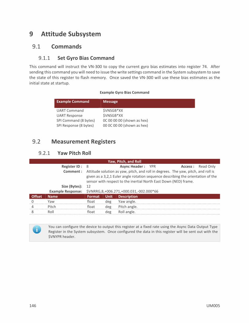
146 UM005
9 Attitude Subsystem
9.1 Commands
9.1.1 Set Gyro Bias Command
This command will instruct the VN-300 to copy the current gyro bias estimates into register 74. After sending this command you will need to issue the write settings command in the System subsystem to save the state of this register to flash memory. Once saved the VN-300 will use these bias estimates as the initial state at startup.
Example Gyro Bias Command
Example Command Message
UART Command $VNSGB*XX UART Response $VNSGB*XX SPI Command (8 bytes) 0C 00 00 00 (shown as hex) SPI Response (8 bytes) 00 0C 00 00 (shown as hex)
9.2 Measurement Registers
9.2.1 Yaw Pitch Roll
Yaw, Pitch, and Roll Register ID : 8 Async Header : YPR Access : Read Only Comment : Attitude solution as yaw, pitch, and roll in degrees. The yaw, pitch, and roll is
given as a 3,2,1 Euler angle rotation sequence describing the orientation of the sensor with respect to the inertial North East Down (NED) frame.
Size (Bytes): 12 Example Response: $VNRRG,8,+006.271,+000.031,-002.000*66
Offset Name Format Unit Description 0 Yaw float deg Yaw angle.
4 Pitch float deg Pitch angle.
8 Roll float deg Roll angle.
You can configure the device to output this register at a fixed rate using the Async Data Output Type Register in the System subsystem. Once configured the data in this register will be sent out with the $VNYPR header.
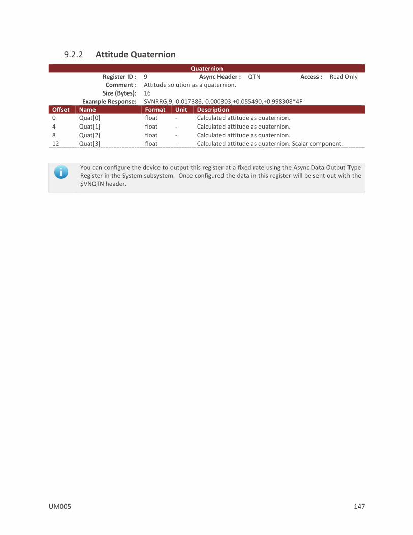
UM005 147
9.2.2 Attitude Quaternion
Quaternion Register ID : 9 Async Header : QTN Access : Read Only Comment : Attitude solution as a quaternion.
Size (Bytes): 16 Example Response: $VNRRG,9,-0.017386,-0.000303,+0.055490,+0.998308*4F
Offset Name Format Unit Description 0 Quat[0] float - Calculated attitude as quaternion.
4 Quat[1] float - Calculated attitude as quaternion.
8 Quat[2] float - Calculated attitude as quaternion.
12 Quat[3] float - Calculated attitude as quaternion. Scalar component.
You can configure the device to output this register at a fixed rate using the Async Data Output Type Register in the System subsystem. Once configured the data in this register will be sent out with the $VNQTN header.
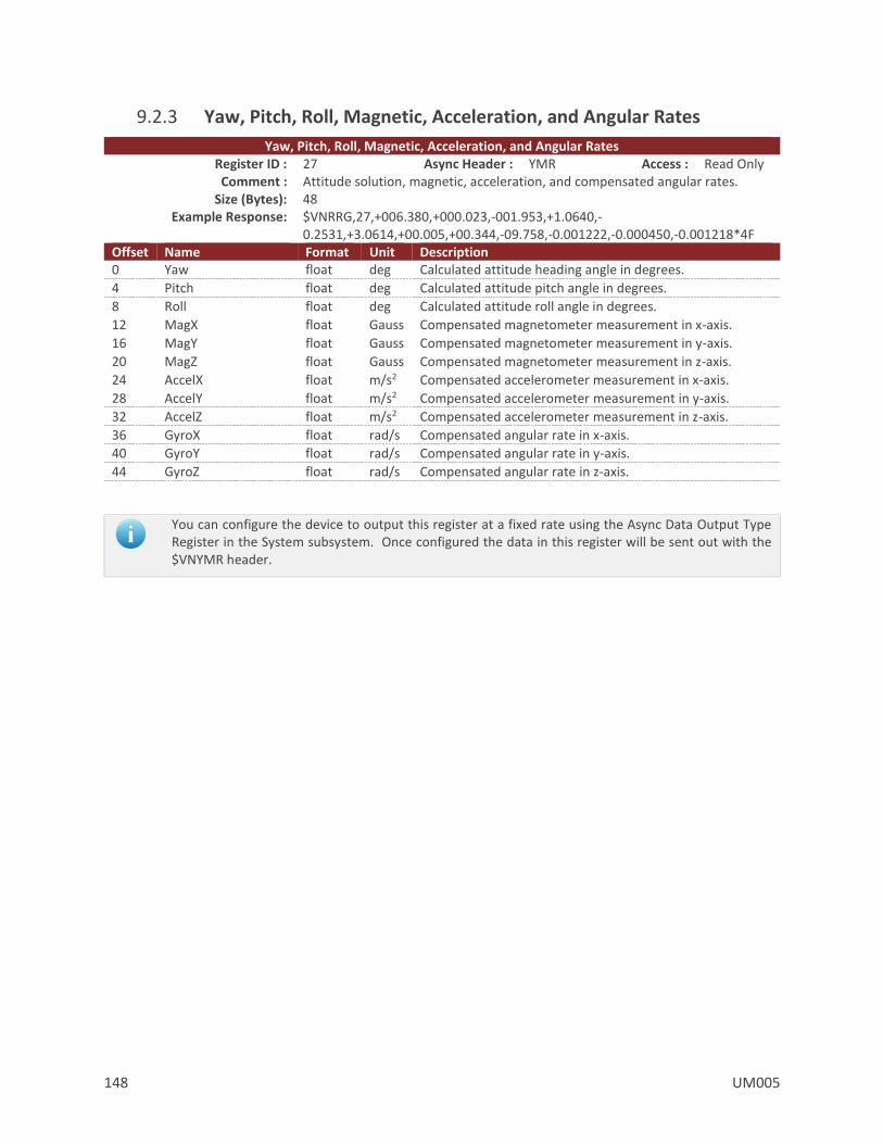
148 UM005
9.2.3 Yaw, Pitch, Roll, Magnetic, Acceleration, and Angular Rates
Yaw, Pitch, Roll, Magnetic, Acceleration, and Angular Rates Register ID : 27 Async Header : YMR Access : Read Only Comment : Attitude solution, magnetic, acceleration, and compensated angular rates.
Size (Bytes): 48 Example Response: $VNRRG,27,+006.380,+000.023,-001.953,+1.0640,-
0.2531,+3.0614,+00.005,+00.344,-09.758,-0.001222,-0.000450,-0.001218*4F Offset Name Format Unit Description 0 Yaw float deg Calculated attitude heading angle in degrees.
4 Pitch float deg Calculated attitude pitch angle in degrees.
8 Roll float deg Calculated attitude roll angle in degrees.
12 MagX float Gauss Compensated magnetometer measurement in x-axis.
16 MagY float Gauss Compensated magnetometer measurement in y-axis.
20 MagZ float Gauss Compensated magnetometer measurement in z-axis.
24 AccelX float m/s2 Compensated accelerometer measurement in x-axis.
28 AccelY float m/s2 Compensated accelerometer measurement in y-axis.
32 AccelZ float m/s2 Compensated accelerometer measurement in z-axis.
36 GyroX float rad/s Compensated angular rate in x-axis.
40 GyroY float rad/s Compensated angular rate in y-axis.
44 GyroZ float rad/s Compensated angular rate in z-axis.
You can configure the device to output this register at a fixed rate using the Async Data Output Type Register in the System subsystem. Once configured the data in this register will be sent out with the $VNYMR header.
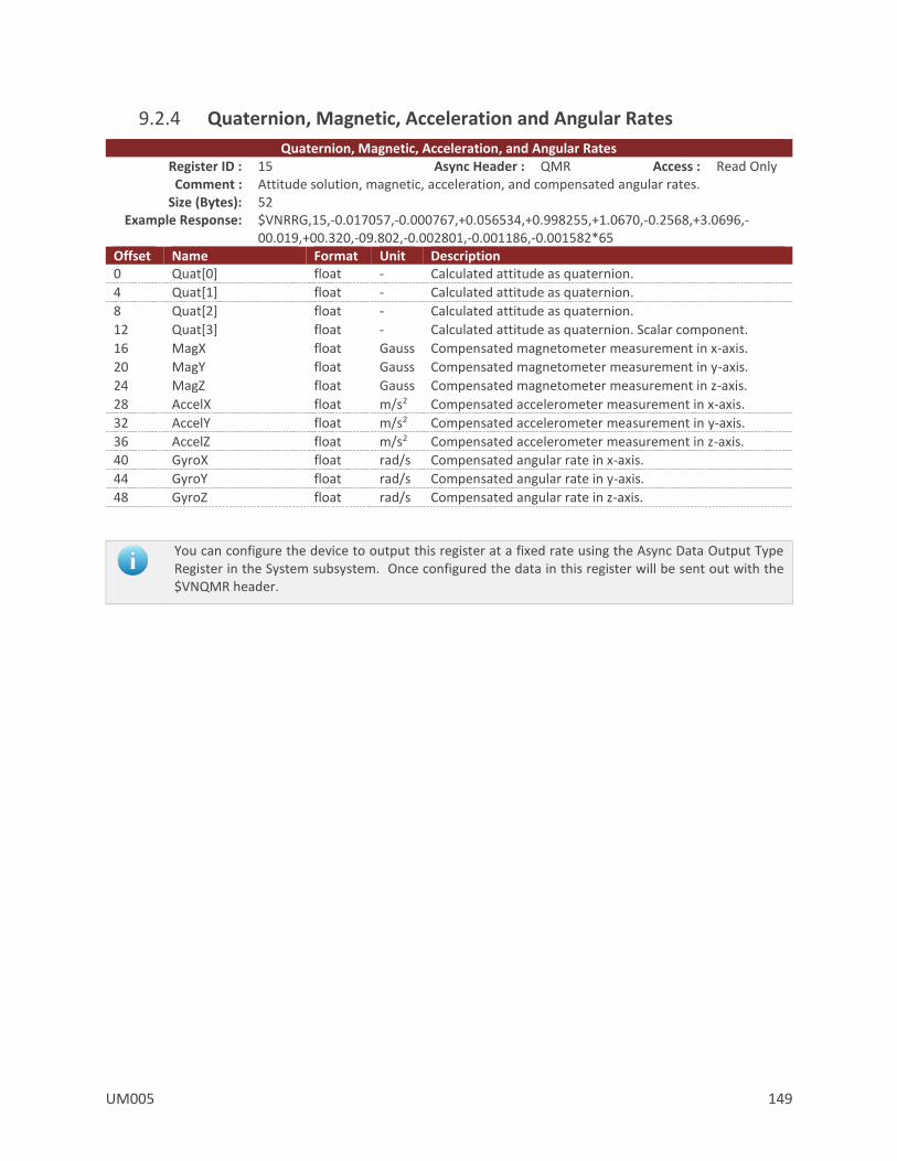
UM005 149
9.2.4 Quaternion, Magnetic, Acceleration and Angular Rates
Quaternion, Magnetic, Acceleration, and Angular Rates Register ID : 15 Async Header : QMR Access : Read Only Comment : Attitude solution, magnetic, acceleration, and compensated angular rates.
Size (Bytes): 52 Example Response: $VNRRG,15,-0.017057,-0.000767,+0.056534,+0.998255,+1.0670,-0.2568,+3.0696,-
00.019,+00.320,-09.802,-0.002801,-0.001186,-0.001582*65 Offset Name Format Unit Description 0 Quat[0] float - Calculated attitude as quaternion.
4 Quat[1] float - Calculated attitude as quaternion.
8 Quat[2] float - Calculated attitude as quaternion.
12 Quat[3] float - Calculated attitude as quaternion. Scalar component.
16 MagX float Gauss Compensated magnetometer measurement in x-axis.
20 MagY float Gauss Compensated magnetometer measurement in y-axis.
24 MagZ float Gauss Compensated magnetometer measurement in z-axis.
28 AccelX float m/s2 Compensated accelerometer measurement in x-axis.
32 AccelY float m/s2 Compensated accelerometer measurement in y-axis.
36 AccelZ float m/s2 Compensated accelerometer measurement in z-axis.
40 GyroX float rad/s Compensated angular rate in x-axis.
44 GyroY float rad/s Compensated angular rate in y-axis.
48 GyroZ float rad/s Compensated angular rate in z-axis.
You can configure the device to output this register at a fixed rate using the Async Data Output Type Register in the System subsystem. Once configured the data in this register will be sent out with the $VNQMR header.

150 UM005
9.2.5 Magnetic Measurements
Magnetic Measurements Register ID : 17 Async Header : MAG Access : Read Only Comment : Magnetometer measurements.
Size (Bytes): 12 Example Response: $VNRRG,17,+1.0647,-0.2498,+3.0628*66
Offset Name Format Unit Description 0 MagX float Gauss Compensated magnetometer measurement in x-axis.
4 MagY float Gauss Compensated magnetometer measurement in y-axis.
8 MagZ float Gauss Compensated magnetometer measurement in z-axis.
You can configure the device to output this register at a fixed rate using the Async Data Output Type Register in the System subsystem. Once configured the data in this register will be sent out with the $VNMAG header.

UM005 151
9.2.6 Acceleration Measurements
Acceleration Measurements Register ID : 18 Async Header : ACC Access : Read Only Comment : Acceleration measurements.
Size (Bytes): 12 Example Response: $VNRRG,18,+00.013,+00.354,-09.801*65
Offset Name Format Unit Description 0 AccelX float m/s2 Compensated accelerometer measurement in x-axis.
4 AccelY float m/s2 Compensated accelerometer measurement in y-axis.
8 AccelZ float m/s2 Compensated accelerometer measurement in z-axis.
You can configure the device to output this register at a fixed rate using the Async Data Output Type Register in the System subsystem. Once configured the data in this register will be sent out with the $VNACC header.
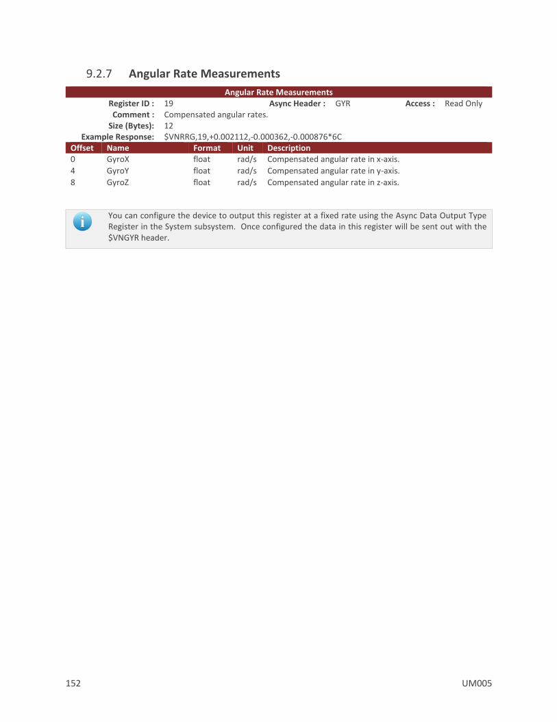
152 UM005
9.2.7 Angular Rate Measurements
Angular Rate Measurements Register ID : 19 Async Header : GYR Access : Read Only Comment : Compensated angular rates.
Size (Bytes): 12 Example Response: $VNRRG,19,+0.002112,-0.000362,-0.000876*6C
Offset Name Format Unit Description 0 GyroX float rad/s Compensated angular rate in x-axis.
4 GyroY float rad/s Compensated angular rate in y-axis.
8 GyroZ float rad/s Compensated angular rate in z-axis.
You can configure the device to output this register at a fixed rate using the Async Data Output Type Register in the System subsystem. Once configured the data in this register will be sent out with the $VNGYR header.
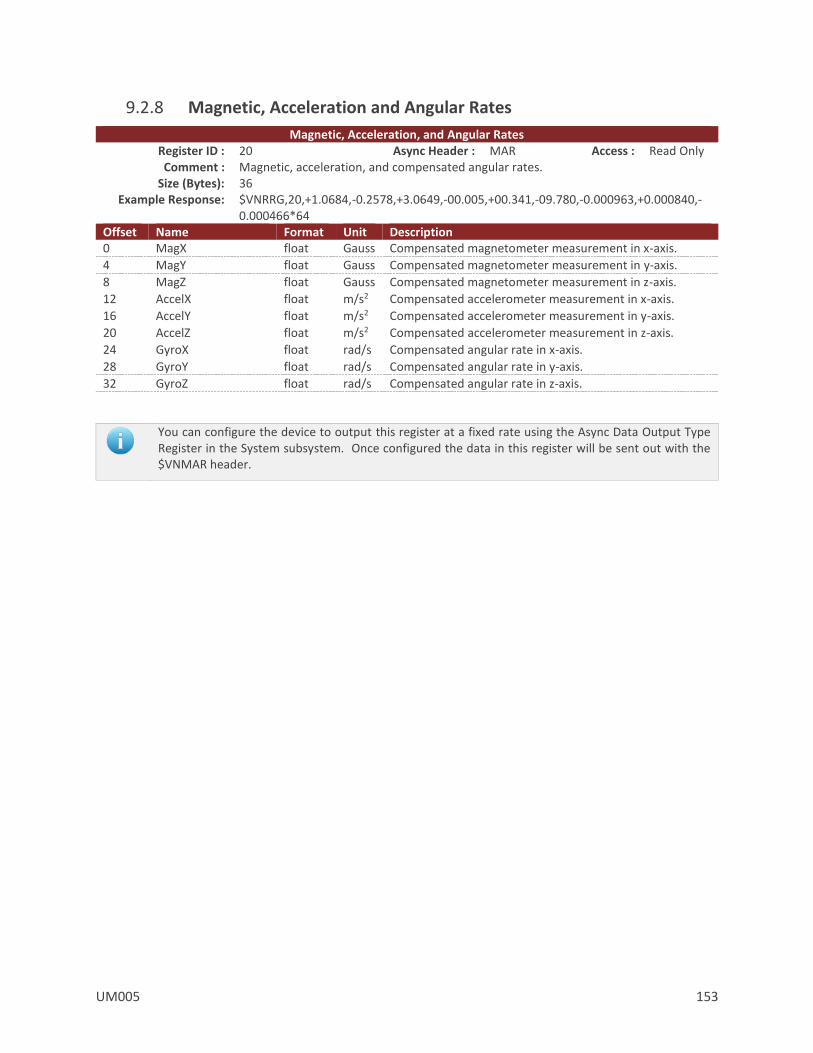
UM005 153
9.2.8 Magnetic, Acceleration and Angular Rates
Magnetic, Acceleration, and Angular Rates Register ID : 20 Async Header : MAR Access : Read Only Comment : Magnetic, acceleration, and compensated angular rates.
Size (Bytes): 36 Example Response: $VNRRG,20,+1.0684,-0.2578,+3.0649,-00.005,+00.341,-09.780,-0.000963,+0.000840,-
0.000466*64 Offset Name Format Unit Description 0 MagX float Gauss Compensated magnetometer measurement in x-axis.
4 MagY float Gauss Compensated magnetometer measurement in y-axis.
8 MagZ float Gauss Compensated magnetometer measurement in z-axis.
12 AccelX float m/s2 Compensated accelerometer measurement in x-axis.
16 AccelY float m/s2 Compensated accelerometer measurement in y-axis.
20 AccelZ float m/s2 Compensated accelerometer measurement in z-axis.
24 GyroX float rad/s Compensated angular rate in x-axis.
28 GyroY float rad/s Compensated angular rate in y-axis.
32 GyroZ float rad/s Compensated angular rate in z-axis.
You can configure the device to output this register at a fixed rate using the Async Data Output Type Register in the System subsystem. Once configured the data in this register will be sent out with the $VNMAR header.
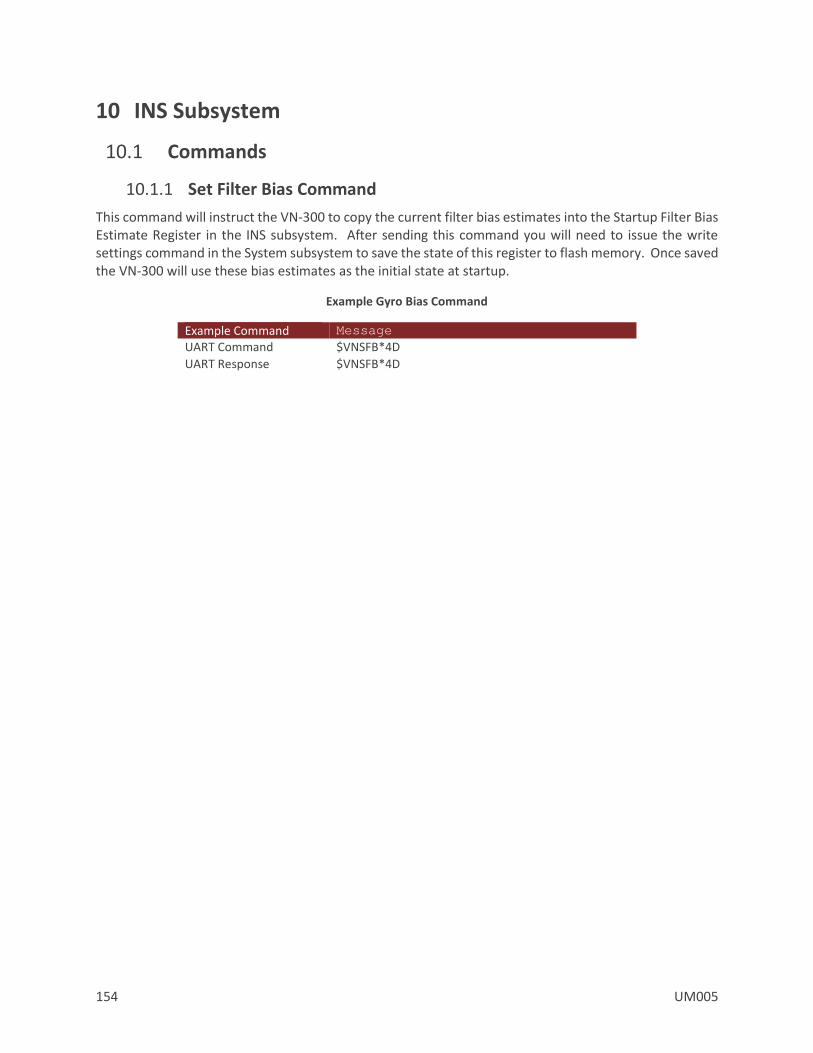
154 UM005
10 INS Subsystem
10.1 Commands
10.1.1 Set Filter Bias Command
This command will instruct the VN-300 to copy the current filter bias estimates into the Startup Filter Bias Estimate Register in the INS subsystem. After sending this command you will need to issue the write settings command in the System subsystem to save the state of this register to flash memory. Once saved the VN-300 will use these bias estimates as the initial state at startup.
Example Gyro Bias Command
Example Command Message
UART Command $VNSFB*4D
UART Response $VNSFB*4D
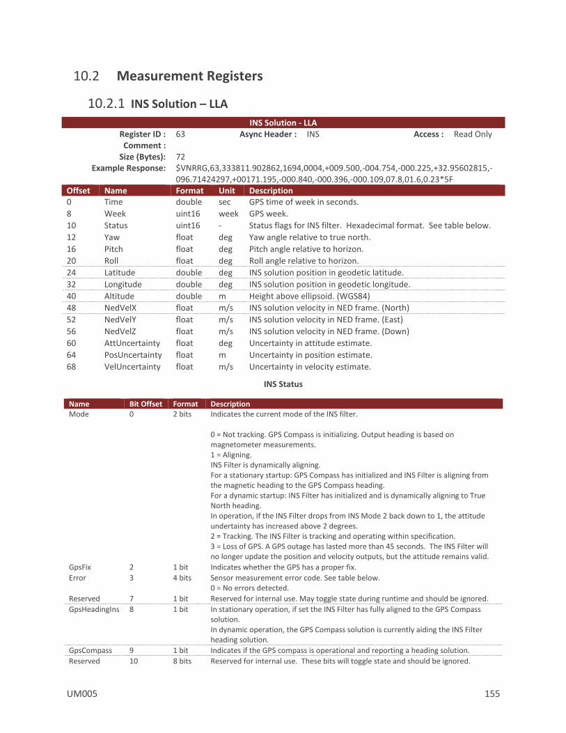
UM005 155
10.2 Measurement Registers
10.2.1 INS Solution – LLA INS Solution - LLA
Register ID : 63 Async Header : INS Access : Read Only Comment :
Size (Bytes): 72 Example Response: $VNRRG,63,333811.902862,1694,0004,+009.500,-004.754,-000.225,+32.95602815,-
096.71424297,+00171.195,-000.840,-000.396,-000.109,07.8,01.6,0.23*5F Offset Name Format Unit Description 0 Time double sec GPS time of week in seconds.
8 Week uint16 week GPS week.
10 Status uint16 - Status flags for INS filter. Hexadecimal format. See table below.
12 Yaw float deg Yaw angle relative to true north.
16 Pitch float deg Pitch angle relative to horizon.
20 Roll float deg Roll angle relative to horizon.
24 Latitude double deg INS solution position in geodetic latitude.
32 Longitude double deg INS solution position in geodetic longitude.
40 Altitude double m Height above ellipsoid. (WGS84)
48 NedVelX float m/s INS solution velocity in NED frame. (North)
52 NedVelY float m/s INS solution velocity in NED frame. (East)
56 NedVelZ float m/s INS solution velocity in NED frame. (Down)
60 AttUncertainty float deg Uncertainty in attitude estimate.
64 PosUncertainty float m Uncertainty in position estimate.
68 VelUncertainty float m/s Uncertainty in velocity estimate.
INS Status
Name Bit Offset Format Description Mode 0 2 bits Indicates the current mode of the INS filter.
0 = Not tracking. GPS Compass is initializing. Output heading is based on magnetometer measurements. 1 = Aligning. INS Filter is dynamically aligning. For a stationary startup: GPS Compass has initialized and INS Filter is aligning from the magnetic heading to the GPS Compass heading. For a dynamic startup: INS Filter has initialized and is dynamically aligning to True North heading. In operation, if the INS Filter drops from INS Mode 2 back down to 1, the attitude undertainty has increased above 2 degrees. 2 = Tracking. The INS Filter is tracking and operating within specification. 3 = Loss of GPS. A GPS outage has lasted more than 45 seconds. The INS Filter will no longer update the position and velocity outputs, but the attitude remains valid.
GpsFix 2 1 bit Indicates whether the GPS has a proper fix.
Error 3 4 bits Sensor measurement error code. See table below. 0 = No errors detected.
Reserved 7 1 bit Reserved for internal use. May toggle state during runtime and should be ignored.
GpsHeadingIns 8 1 bit In stationary operation, if set the INS Filter has fully aligned to the GPS Compass solution. In dynamic operation, the GPS Compass solution is currently aiding the INS Filter heading solution.
GpsCompass 9 1 bit Indicates if the GPS compass is operational and reporting a heading solution.
Reserved 10 8 bits Reserved for internal use. These bits will toggle state and should be ignored.
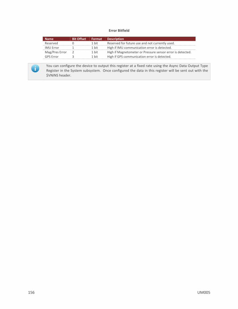
156 UM005
Error Bitfield
Name Bit Offset Format Description Reserved 0 1 bit Reserved for future use and not currently used.
IMU Error 1 1 bit High if IMU communication error is detected.
Mag/Pres Error 2 1 bit High if Magnetometer or Pressure sensor error is detected.
GPS Error 3 1 bit High if GPS communication error is detected.
You can configure the device to output this register at a fixed rate using the Async Data Output Type Register in the System subsystem. Once configured the data in this register will be sent out with the $VNINS header.

UM005 157
10.2.2 INS Solution - ECEF
INS Solution – ECEF Register ID : 64 Async Header : INE Access : Read Only Comment :
Size (Bytes): 72 Example Response: $VNRRG,64,333837.222917,1694,0004,+009.315,-004.767,-000.193,-0626356.433,-
5320530.947,+3449961.679,-000.224,-000.476,-000.564,07.7,01.5,0.22*65 Offset Name Format Unit Description 0 Time double sec GPS time of week in seconds.
8 Week uint16 week GPS week.
10 Status uint16 - Status flags for INS filter. See table below.
12 Yaw float deg Yaw angle relative to true north.
16 Pitch float deg Pitch angle relative to horizon.
20 Roll float deg Roll angle relative to horizon.
24 PositionX double m INS solution position in ECEF. (X-axis)
32 PositionY double m INS solution position in ECEF. (Y-axis)
40 PositionZ double m INS solution position in ECEF. (Z-axis)
48 VelocityX float m/s INS solution velocity in ECEF frame. (X-axis)
52 VelocityY float m/s INS solution velocity in ECEF frame. (Y-axis)
56 VelocityZ float m/s INS solution velocity in ECEF frame. (Z-axis)
60 AttUncertainty float deg Expected uncertainty in estimated attitude.
64 PosUncertainty float m Expected uncertainty in estimated position.
68 VelUncertainty float m/s Expected uncertainty in estimated velocity.
Table 23 - INS Status
Name Bit Offset Format Description Mode 0 2 bits Indicates the current mode of the INS filter.
0 = Not tracking. GPS Compass is initializing. Output heading is based on magnetometer measurements. 1 = Aligning. INS Filter is dynamically aligning. For a stationary startup: GPS Compass has initialized and INS Filter is aligning from the magnetic heading to the GPS Compass heading. For a dynamic startup: INS Filter has initialized and is dynamically aligning to True North heading. In operation, if the INS Filter drops from INS Mode 2 back down to 1, the attitude undertainty has increased above 2 degrees. 2 = Tracking. The INS Filter is tracking and operating within specification. 3 = Loss of GPS. A GPS outage has lasted more than 45 seconds. The INS Filter will no longer update the position and velocity outputs, but the attitude remains valid.
GpsFix 2 1 bit Indicates whether the GPS has a proper fix. Error 3 4 bits Sensor measurement error code. See table below.
0 = No errors detected. Reserved 7 1 bit Reserved for internal use. May toggle state during runtime and should be ignored. GpsHeadingIns 8 1 bit In stationary operation, if set the INS Filter has fully aligned to the GPS Compass
solution. In dynamic operation, the GPS Compass solution is currently aiding the INS Filter heading solution.
GpsCompass 9 1 bit Indicates if the GPS compass is operational and reporting a heading solution.
Reserved 10 8 bits Reserved for internal use. These bits will toggle state and should be ignored.

158 UM005
Table 24 - Error Bitfield
Name Bit Offset Format Description Reserved 0 1 bit Reserved for future use and not currently used. IMU Error 1 1 bit High if IMU communication error is detected. Mag/Pres Error 2 1 bit High if Magnetometer or Pressure sensor error is detected. GPS Error 3 1 bit High if GPS communication error is detected.
You can configure the device to output this register at a fixed rate using the Async Data Output Type Register in the System subsystem. Once configured the data in this register will be sent out with the $VNINE header.

UM005 159
10.2.3 INS State - LLA
INS State – LLA Register ID : 72 Async Header : ISL Access : Read Only Comment :
Size (Bytes): 72 Example Response: $VNRRG,72,+170.420,+001.398,+001.806,+00.000295,-00.000911,-
00.000905,+32.95680804,-096.71414860,+00179.592,+000.181,-000.073,-000.050,+00.209,-00.322,-10.040*52
Offset Name Format Unit Description 0 Yaw float deg Yaw angle relative to true north.
4 Pitch float deg Pitch angle relative to horizon.
8 Roll float deg Roll angle relative to horizon.
12 Latitude double deg Estimated position in geodetic latitude.
20 Longitude double deg Estimated position in geodetic longitude.
28 Altitude double m Estimated height above ellipsoid. (WGS84)
36 VelocityX float m/s Estimated velocity in NED frame. (North)
40 VelocityY float m/s Estimated velocity in NED frame. (East)
44 VelocityZ float m/s Estimated velocity in NED frame. (Down)
48 AccelX float m/s2 Estimated acceleration in body frame. (X-axis)
52 AccelY float m/s2 Estimated acceleration in body frame. (Y-axis)
56 AccelZ float m/s2 Estimated acceleration in body frame. (Z-axis)
60 AngularRateX float rad/s Estimated angular rate in body frame. (X-axis)
64 AngularRateY float rad/s Estimated angular rate in body frame. (Y-axis)
68 AngularRateZ float rad/s Estimated angular rate in body frame. (Z-axis)
You can configure the device to output this register at a fixed rate using the Async Data Output Type Register in the System subsystem. Once configured the data in this register will be sent out with the $VNISL header.
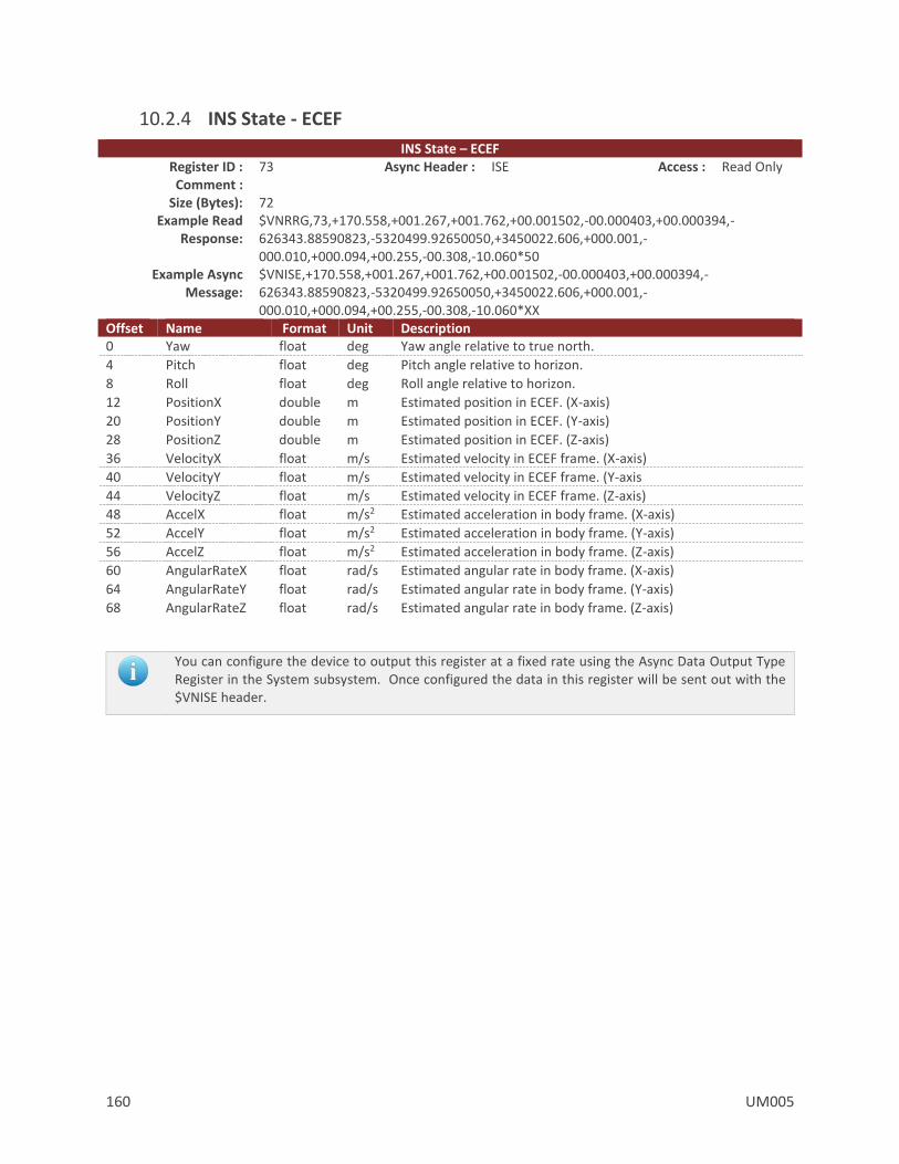
160 UM005
10.2.4 INS State - ECEF
INS State – ECEF Register ID : 73 Async Header : ISE Access : Read Only Comment :
Size (Bytes): 72 Example Read
Response: $VNRRG,73,+170.558,+001.267,+001.762,+00.001502,-00.000403,+00.000394,-626343.88590823,-5320499.92650050,+3450022.606,+000.001,-000.010,+000.094,+00.255,-00.308,-10.060*50
Example Async Message:
$VNISE,+170.558,+001.267,+001.762,+00.001502,-00.000403,+00.000394,-626343.88590823,-5320499.92650050,+3450022.606,+000.001,-000.010,+000.094,+00.255,-00.308,-10.060*XX
Offset Name Format Unit Description 0 Yaw float deg Yaw angle relative to true north.
4 Pitch float deg Pitch angle relative to horizon.
8 Roll float deg Roll angle relative to horizon.
12 PositionX double m Estimated position in ECEF. (X-axis)
20 PositionY double m Estimated position in ECEF. (Y-axis)
28 PositionZ double m Estimated position in ECEF. (Z-axis)
36 VelocityX float m/s Estimated velocity in ECEF frame. (X-axis)
40 VelocityY float m/s Estimated velocity in ECEF frame. (Y-axis
44 VelocityZ float m/s Estimated velocity in ECEF frame. (Z-axis)
48 AccelX float m/s2 Estimated acceleration in body frame. (X-axis)
52 AccelY float m/s2 Estimated acceleration in body frame. (Y-axis)
56 AccelZ float m/s2 Estimated acceleration in body frame. (Z-axis)
60 AngularRateX float rad/s Estimated angular rate in body frame. (X-axis)
64 AngularRateY float rad/s Estimated angular rate in body frame. (Y-axis)
68 AngularRateZ float rad/s Estimated angular rate in body frame. (Z-axis)
You can configure the device to output this register at a fixed rate using the Async Data Output Type Register in the System subsystem. Once configured the data in this register will be sent out with the $VNISE header.
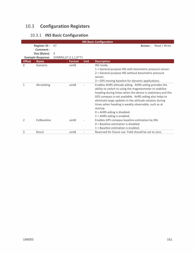
UM005 161
10.3 Configuration Registers
10.3.1 INS Basic Configuration
INS Basic Configuration Register ID : 67 Access : Read / Write Comment :
Size (Bytes): 4 Example Response: $VNRRG,67,3,1,1,0*71
Offset Name Format Unit Description 0 Scenario uint8 - INS mode.
1 = General purpose INS with barometric pressure sensor. 2 = General purpose INS without barometric pressure sensor. 3 = GPS moving baseline for dynamic applications.
1 AhrsAiding uint8 - Enables AHRS attitude aiding. AHRS aiding provides the ability to switch to using the magnetometer to stabilize heading during times when the device is stationary and the GPS compass is not available. AHRS aiding also helps to eliminate large updates in the attitude solution during times when heading is weakly observable, such as at startup. 0 = AHRS aiding is disabled. 1 = AHRS aiding is enabled.
2 EstBaseline uint8 - Enables GPS compass baseline estimation by INS. 0 = Baseline estimation is disabled. 1 = Baseline estimation is enabled.
3 Resv2 uint8 - Reserved for future use. Field should be set to zero.
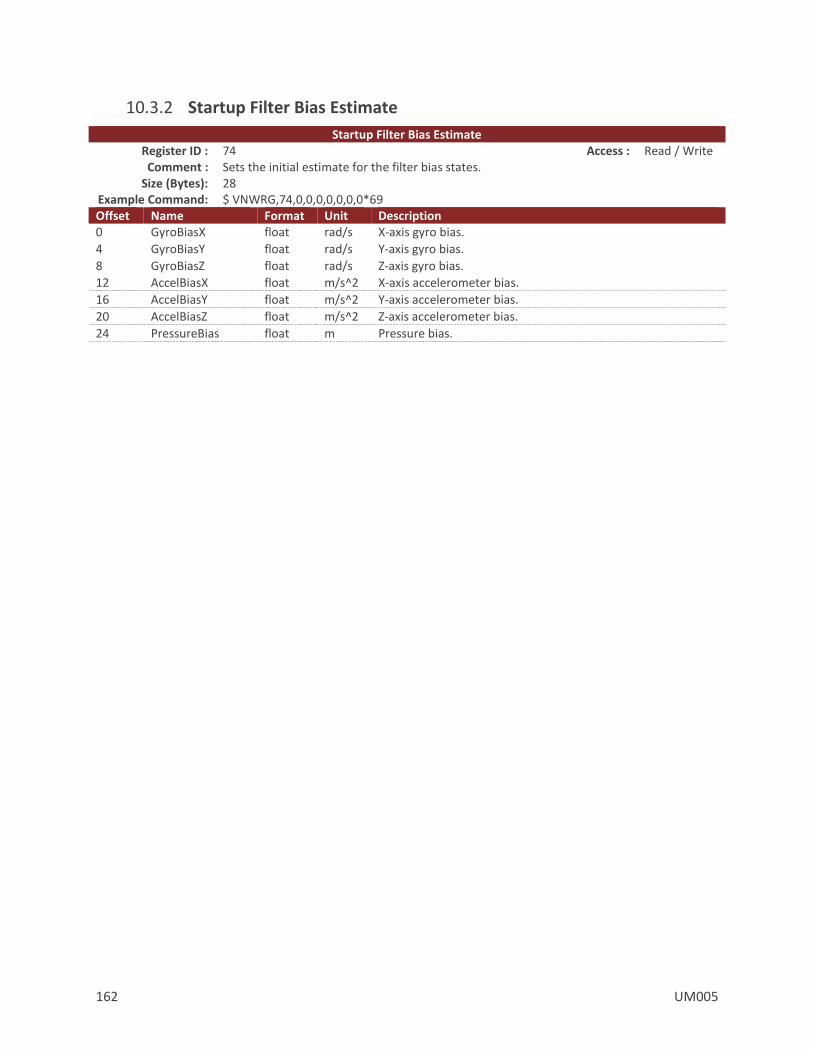
162 UM005
10.3.2 Startup Filter Bias Estimate
Startup Filter Bias Estimate Register ID : 74 Access : Read / Write Comment : Sets the initial estimate for the filter bias states.
Size (Bytes): 28 Example Command: $ VNWRG,74,0,0,0,0,0,0,0*69 Offset Name Format Unit Description 0 GyroBiasX float rad/s X-axis gyro bias.
4 GyroBiasY float rad/s Y-axis gyro bias.
8 GyroBiasZ float rad/s Z-axis gyro bias.
12 AccelBiasX float m/s^2 X-axis accelerometer bias.
16 AccelBiasY float m/s^2 Y-axis accelerometer bias.
20 AccelBiasZ float m/s^2 Z-axis accelerometer bias.
24 PressureBias float m Pressure bias.

UM005 163
10.4 Factory Defaults Settings Name Default Factory Value INS Basic Configuration 3,0,1,0
Startup Filter Bias Estimate 0,0,0,0,0,0,0
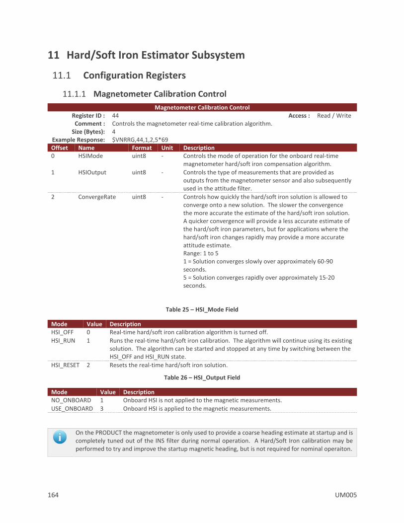
164 UM005
11 Hard/Soft Iron Estimator Subsystem
11.1 Configuration Registers
11.1.1 Magnetometer Calibration Control
Magnetometer Calibration Control Register ID : 44 Access : Read / Write Comment : Controls the magnetometer real-time calibration algorithm.
Size (Bytes): 4 Example Response: $VNRRG,44,1,2,5*69 Offset Name Format Unit Description 0 HSIMode uint8 - Controls the mode of operation for the onboard real-time
magnetometer hard/soft iron compensation algorithm.
1 HSIOutput uint8 - Controls the type of measurements that are provided as outputs from the magnetometer sensor and also subsequently used in the attitude filter.
2 ConvergeRate uint8 - Controls how quickly the hard/soft iron solution is allowed to converge onto a new solution. The slower the convergence the more accurate the estimate of the hard/soft iron solution. A quicker convergence will provide a less accurate estimate of the hard/soft iron parameters, but for applications where the hard/soft iron changes rapidly may provide a more accurate attitude estimate. Range: 1 to 5 1 = Solution converges slowly over approximately 60-90 seconds. 5 = Solution converges rapidly over approximately 15-20 seconds.
Table 25 – HSI_Mode Field
Mode Value Description HSI_OFF 0 Real-time hard/soft iron calibration algorithm is turned off.
HSI_RUN 1 Runs the real-time hard/soft iron calibration. The algorithm will continue using its existing solution. The algorithm can be started and stopped at any time by switching between the HSI_OFF and HSI_RUN state.
HSI_RESET 2 Resets the real-time hard/soft iron solution.
Table 26 – HSI_Output Field
Mode Value Description NO_ONBOARD 1 Onboard HSI is not applied to the magnetic measurements.
USE_ONBOARD 3 Onboard HSI is applied to the magnetic measurements.
On the PRODUCT the magnetometer is only used to provide a coarse heading estimate at startup and is completely tuned out of the INS filter during normal operation. A Hard/Soft Iron calibration may be performed to try and improve the startup magnetic heading, but is not required for nominal operaiton.
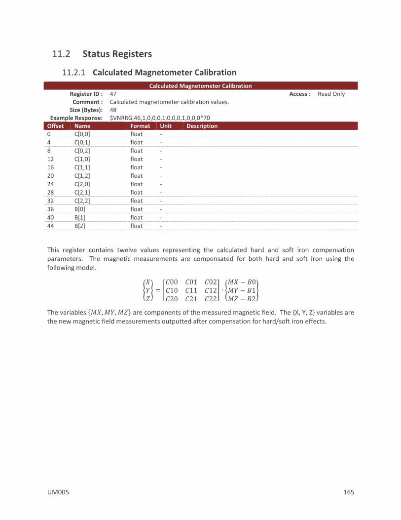
UM005 165
11.2 Status Registers
11.2.1 Calculated Magnetometer Calibration
Calculated Magnetometer Calibration Register ID : 47 Access : Read Only Comment : Calculated magnetometer calibration values.
Size (Bytes): 48 Example Response: $VNRRG,46,1,0,0,0,1,0,0,0,1,0,0,0*70
Offset Name Format Unit Description 0 C[0,0] float -
4 C[0,1] float -
8 C[0,2] float -
12 C[1,0] float -
16 C[1,1] float -
20 C[1,2] float -
24 C[2,0] float -
28 C[2,1] float -
32 C[2,2] float -
36 B[0] float -
40 B[1] float -
44 B[2] float -
This register contains twelve values representing the calculated hard and soft iron compensation parameters. The magnetic measurements are compensated for both hard and soft iron using the following model.
𝑋𝑌𝑍 = [
𝐶00 𝐶01 𝐶02𝐶10 𝐶11 𝐶12𝐶20 𝐶21 𝐶22
] ∙ 𝑀𝑋 − 𝐵0𝑀𝑌 − 𝐵1𝑀𝑍 − 𝐵2
The variables 𝑀𝑋,𝑀𝑌,𝑀𝑍 are components of the measured magnetic field. The X, Y, Z variables are the new magnetic field measurements outputted after compensation for hard/soft iron effects.

166 UM005
11.3 Factory Defaults Settings Name Default Factory Value Magnetometer Calibration Control 1,3,5
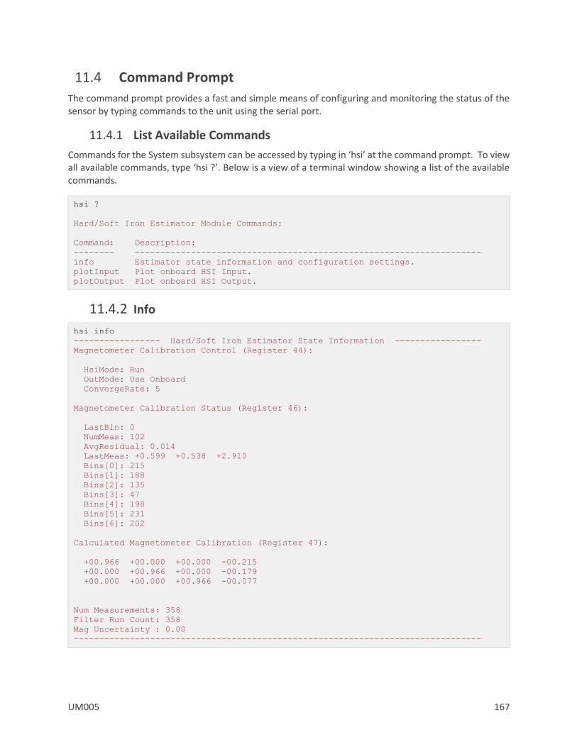
UM005 167
11.4 Command Prompt
The command prompt provides a fast and simple means of configuring and monitoring the status of the sensor by typing commands to the unit using the serial port.
11.4.1 List Available Commands
Commands for the System subsystem can be accessed by typing in ‘hsi’ at the command prompt. To view all available commands, type ‘hsi ?’. Below is a view of a terminal window showing a list of the available commands.
hsi ?
Hard/Soft Iron Estimator Module Commands:
Command: Description:
-------- --------------------------------------------------------------------
info Estimator state information and configuration settings.
plotInput Plot onboard HSI Input.
plotOutput Plot onboard HSI Output.
11.4.2 Info
hsi info
----------------- Hard/Soft Iron Estimator State Information -----------------
Magnetometer Calibration Control (Register 44):
HsiMode: Run
OutMode: Use Onboard
ConvergeRate: 5
Magnetometer Calibration Status (Register 46):
LastBin: 0
NumMeas: 102
AvgResidual: 0.014
LastMeas: +0.599 +0.538 +2.910
Bins[0]: 215
Bins[1]: 188
Bins[2]: 135
Bins[3]: 47
Bins[4]: 198
Bins[5]: 231
Bins[6]: 202
Calculated Magnetometer Calibration (Register 47):
+00.966 +00.000 +00.000 -00.215
+00.000 +00.966 +00.000 -00.179
+00.000 +00.000 +00.966 -00.077
Num Measurements: 358
Filter Run Count: 358
Mag Uncertainty : 0.00
--------------------------------------------------------------------------------

168 UM005
11.4.3 PlotInput
hsi plotinput
--------------------- HSI Estimator Magnetic Input Plot ----------------------
Uncalibrated XY
+-------------------+-------------------+-------------------+-------------------+
| | * * * | * * | |
| | **** * * * * *** | |
| | * * * * | ** | |
| * * * * * |* * * | |
| *** ** * * * ** * | |
| *** | * * * * * | ** * |
| * |* * ** * * | * * * |* * |
| * | * *| * | |
| * *| * * * | * ** * |
+---------***-------+-----------*-------*----*--*-----*-----+----------*--------+
| * | * * * * | ** |
| * * * | * * *** |
| * ** * | * | * * | |
| ** | * ** | | * * |
| * * | * * * | * | |
| *** | *| * * * * | * |
| * | * * | * | * * * |
| * | * | * | * * |
| * ** | | * * | * |
+---*-*-*-----------+---*---------------+--------*-----*----+*------*-------*---+
| * | * | * | * * |
| * * * | | ** | * |
| | * * ** * *| * | * |
| * ** * | * * ** * * * * ** ** * |
| * * | * * | | ** |
| ** | * | * | * |
| * * * * | * | * |
| ** | | * * | ** |
| *** * * | | * | *** |
+--------**--------*+-------------------+-------------------+-----***-----------+
| **** * | * * * * * |* ** |
| * * * | * | ** |
| *** | | | * * |
| * | * | * * |
| | * | * * | |
| | | | |
| | * | | |
| | | | |
| | | | |
+-------------------+-------------------+-------------------+-------------------+
Plot Center : +0.000, +0.000
Plot Scale : +1.042, +1.042
--------------------------------------------------------------------------------
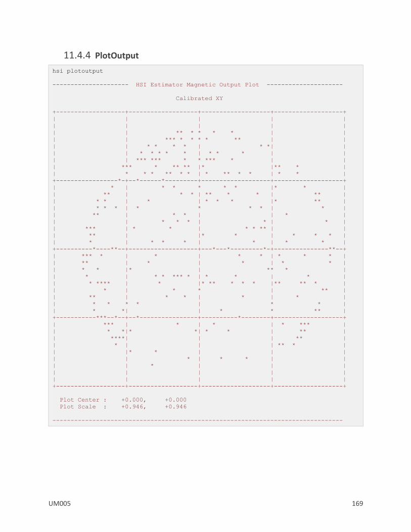
UM005 169
11.4.4 PlotOutput
hsi plotoutput
--------------------- HSI Estimator Magnetic Output Plot ---------------------
Calibrated XY
+-------------------+-------------------+-------------------+-------------------+
| | | | |
| | | | |
| | ** * * * * | |
| | *** * * * * ** | |
| | * * * * | * *| |
| | * * * * * | * * * | |
| | *** *** * * *** * | |
| *** * ** ** |* |** * |
| * * * ** * * | * ** * * | * * |
+-----------------*-+--*------*---------+-------------------+-------------------+
| * | * * * * * |* * |
| ** | * * | ** * * | ** |
| * * | * | * * * |* ** |
| * * * | * * * * | * |
| ** | * * | | * |
| | * * * | * | * |
| *** | * * | * * ** | |
| ** | |* * | * * * |
| * | * * * | * | * * |
+----------*----**--+-------------------+---*---*---------*-+---------------**--+
| *** * | * | * * | * * * |
| ** | * | * | * * |
| * * |* | ** * |
| * | * * *** * | * * | * |
| * **** | * |* ** * * * |** ** * |
| * | * * | ** |
| ** | * * | * | * |
| * * * * | * * |
| * *| | * * ** |
+-----------***--*--+--*----------------+----------*--------+-------------------+
| *** | * | * | * *** |
| * *|* *| * * | ** |
| ****| | | ** |
| * | | | ** * |
| |* * | | |
| | * | * * | |
| | * | | |
| | | | |
| | | | |
+-------------------+-------------------+-------------------+-------------------+
Plot Center : +0.000, +0.000
Plot Scale : +0.946, +0.946
--------------------------------------------------------------------------------

170 UM005
12 World Magnetic & Gravity Module
12.1 Configuration Registers
12.1.1 Magnetic and Gravity Reference Vectors
Magnetic and Gravity Reference Vectors Register ID : 21 Firmware : 0.3.0.0 Access: Read / Write Comment : Magnetic and gravity reference vectors.
Size (Bytes): 24 Example Command: $VNWRG,21,1,0,1.8,0,0,-9.79375*56
Offset Name Format Unit Description 0 MagRefX float Gauss X-Axis Magnetic Reference
4 MagRefY float Gauss Y-Axis Magnetic Reference
8 MagRefZ float Gauss Z-Axis Magnetic Reference
12 AccRefX float m/s2 X-Axis Gravity Reference
16 AccRefY float m/s2 Y-Axis Gravity Reference
20 AccRefZ float m/s2 Z-Axis Gravity Reference
This register contains the reference vectors for the magnetic and gravitational fields as used by the
onboard filter. The values map to either the user-set values or the results of calculations of the onboard
reference models (see the Reference Vector Configuration Register in the IMU subsystem). When the
reference values come from the onboard model(s), those values are read-only. When the reference
models are disabled, the values reflect the user reference vectors and will be writable. For example, if
the onboard World Magnetic Model is enabled and the onboard Gravitational Model is disabled, only
the gravity reference values will be modified on a register write. Note that the user reference vectors
will not be overwritten by the onboard models, but will retain their previous values for when the
onboard models are disabled.

UM005 171
12.1.2 Reference Vector Configuration
Reference Vector Configuration Register ID : 83 Firmware : v0.3.0.0 Access : Read / Write Comment : Control register for both the onboard world magnetic and gravity model corrections.
Size (Bytes): 32 Example Response: $VNRRG,83,0,0,0,0,1000,0.000,+00.00000000,+000.00000000,+00000.000*4E
Offset Name Format Unit Description 0 UseMagModel uint8 - Set to 1 to use the world magnetic model.
1 UseGravityModel uint8 - Set to 1 to use the world gravity model.
2 Resv1 uint8 - Reserved for future use. Must be set to zero.
3 Resv2 uint8 - Reserved for future use. Must be set to zero.
4 RecalcThreshold uint32 - Maximum distance traveled before magnetic and gravity models are recalculated for the new position.
8 Year float year The reference date expressed as a decimal year. Used for both the magnetic and gravity models.
12 **** 4 byte padding ***
16 Latitude double deg The reference latitude position in degrees.
24 Longitude double deg The reference longitude position in degrees.
32 Altitude double m The reference altitude above the reference ellipsoid in meters.
This register allows configuration of the onboard spherical harmonic models used to calculate the local magnetic and gravitational reference values. Having accurate magnetic reference values improves the accuracy of heading when using the magnetometer and accounts for magnetic declination. Having accurate gravitational reference values improves accuracy by allowing the INS filter to more accurately estimate the accelerometer biases. The VN-300 currently includes the EGM96 gravitational model and the WMM2010 magnetic model. The models are upgradable to allow updating to future models when available.
The magnetic and gravity models can be individually enabled or disabled using the UseMagModel and UseGravityModel parameters, respectively. When disabled, the corresponding values set by the user in the Reference Vector Register in the IMU subsystem will be used instead of values calculated by the onboard model.
The VN-300 starts up with the user configured reference vector values. Shortly after startup (and if the models are enabled), the location and time set in this register will be used to update the reference vectors. When a 3D GPS fix is available, the location and time reported by the GPS will be used to update the model. If GPS is lost, the reference vectors will hold their last valid values. The model values will be recalculated whenever the current position has changed by the RecaclThreshold or the date has changed by more than approximately 8 hours, whichever comes first.

172 UM005
12.2 Factory Defaults Settings Name Default Factory Value Magnetic and Gravity Reference Vectors 1,0,1.8,0,0,-9.793746
Reference Vector Configuration 1,1,0,0,1000,0,0,0,0
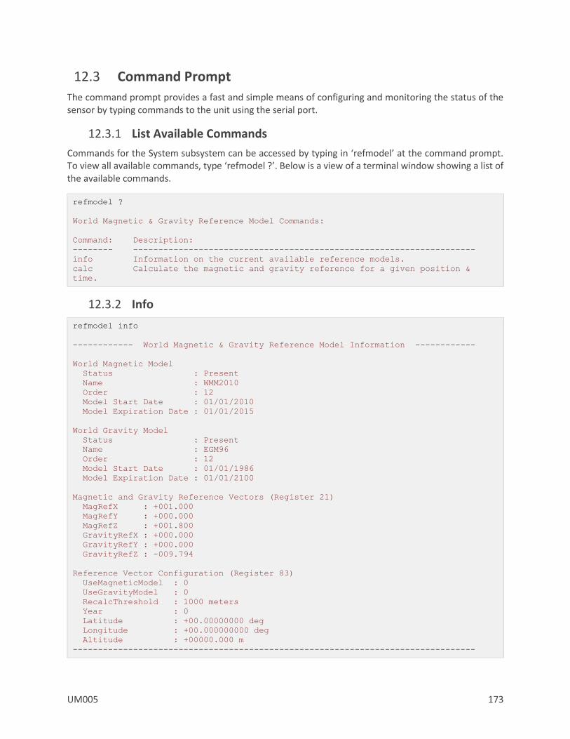
UM005 173
12.3 Command Prompt
The command prompt provides a fast and simple means of configuring and monitoring the status of the sensor by typing commands to the unit using the serial port.
12.3.1 List Available Commands
Commands for the System subsystem can be accessed by typing in ‘refmodel’ at the command prompt. To view all available commands, type ‘refmodel ?’. Below is a view of a terminal window showing a list of the available commands.
refmodel ?
World Magnetic & Gravity Reference Model Commands:
Command: Description:
-------- --------------------------------------------------------------------
info Information on the current available reference models.
calc Calculate the magnetic and gravity reference for a given position &
time.
12.3.2 Info
refmodel info
------------ World Magnetic & Gravity Reference Model Information ------------
World Magnetic Model
Status : Present
Name : WMM2010
Order : 12
Model Start Date : 01/01/2010
Model Expiration Date : 01/01/2015
World Gravity Model
Status : Present
Name : EGM96
Order : 12
Model Start Date : 01/01/1986
Model Expiration Date : 01/01/2100
Magnetic and Gravity Reference Vectors (Register 21)
MagRefX : +001.000
MagRefY : +000.000
MagRefZ : +001.800
GravityRefX : +000.000
GravityRefY : +000.000
GravityRefZ : -009.794
Reference Vector Configuration (Register 83)
UseMagneticModel : 0
UseGravityModel : 0
RecalcThreshold : 1000 meters
Year : 0
Latitude : +00.00000000 deg
Longitude : +00.000000000 deg
Altitude : +00000.000 m
--------------------------------------------------------------------------------

174 UM005
Please Read Carefully:
Information in this document is provided solely in connection with VectorNav Technologies, LLC (“VectorNav”) products. VectorNav reserves the right to make changes, corrections, modifications, or improvements to this document, and the products and services described herein at any time, without notice.
All VectorNav products are sold pursuant of VectorNav’s terms and conditions of sale.
No license to any intellectual property, expressed or implied, is granted under this document. If any part of this document refers to any third party products or services it shall not be deemed a license grant by VectorNav for the use of such third party products or services, or any intellectual property contained therein or considered as a warranty covering the use in any manner whatsoever of such third party products or services or any intellectual property contained therein.
Information in this document supersedes and replaces all information previously supplied.
The VectorNav logo is a registered trademark of VectorNav Technologies, LLC. All other names are the property of their respective owners.
© 2017 VectorNav Technologies, LLC – All rights reserved


![AGENDA AT A GLANCE · 2020. 9. 11. · INTERNET OF THINGS [IOT] CUSTOMER EXPERIENCE [CX] DEVOPS VN / ID TH / ID TH / VN VN TH / ID TH / VN / ID VN Application integration patterns](https://img.pdfslide.us/doc/110x75/600d7d2ff10c1d69245d15da/agenda-at-a-glance-2020-9-11-internet-of-things-iot-customer-experience-cx.jpg)