Embed Size (px)
Citation preview

Embedded Box PC B O X E R - 6 9 1 4
BOXER-6914 Fanless Embedded Box PC Intel® Atom™ D2550 1.86GHz
Processor CFast™/SIM Slot
2 DIO, 14/16 COMs 2 USB 3.0, 4 USB 2.0
BOXER-6914 Manual 1st Ed. April 10, 2015

Embedded Box PC B O X E R - 6 9 1 4
Copyright Notice
This document is copyrighted, 2015. All rights are reserved. The original manufacturer reserves the right to make improvements to the products described in this manual at any time without notice.
No part of this manual may be reproduced, copied, translated, or transmitted in any form or by any means without the prior written permission of the original manufacturer. Information provided in this manual is intended to be accurate and reliable. However, the original manufacturer assumes no responsibility for its use, or for any in-fringements upon the rights of third parties that may result from its use.
The material in this document is for product information only and is subject to change without notice. While reasonable efforts have been made in the preparation of this document to assure its accuracy, AAEON assumes no liabilities resulting from errors or omissions in this document, or from the use of the information contained herein.
AAEON reserves the right to make changes in the product design without notice to its users.
i
Embedded Box PC B O X E R - 6 9 1 4
Acknowledgments
• AMI is a trademark of American Megatrends Inc.
• CFast™ is a trademark of the Compact Flash Association.
• Intel®, Atom™ are trademarks of Intel® Corporation.
• Microsoft Windows® is a registered trademark of Microsoft
Corp.
• PC/AT, PS/2, and VGA are trademarks of International Business Machines Corporation.
All other product names or trademarks are properties of their respective owners.
ii
Embedded Box PC B O X E R - 6 9 1 4
Packing List
Before you begin operating your PC, please make sure that the following materials have been shipped:
1 BOXER-6914 Embedded Box PC
1 Phoenix Power Connector
4 M3 x 4mm Screws
4 6# -32 x 10mm Screws
2 Wallmount Brackets
1 DVD-ROM for manual (in PDF format) and
Drivers
If any of these items should be missing or damaged, please contact your distributor or sales representative immediately.
iii

Embedded Box PC B O X E R - 6 9 1 4
Safety & Warranty Please read the following safety instructions carefully. It is advised
that you keep this manual for future references
1. Disconnect this device from any AC supply before cleaning.
2. While cleaning, use a damp cloth instead of liquid or spray
detergents.
3. For any pluggable equipment, the power outlet must be installed
near the device and easily accessible.
4. Keep this device away from humidity.
5. Place this device on a solid surface during installation. Dropping
it or letting it fall could cause damage.
6. The openings on the device’s enclosure are for dissipating heat.
DO NOT COVER THE OPENINGS.
7. Watch out for high temperatures that may occur during system
operation.
8. Make sure the voltage of the power source is correct before
connecting the device to the power outlet.
9. Position the power cord so that people cannot step on it. Do not
place anything over the power cord.
10. All cautions and warnings on the device should be noted.
11. If the device is not to be used for a long time, disconnect it from
the power supply to avoid damage by transient over-voltage.
12. Never pour any liquid into the openings. This could cause fire or
electric shock.
iv

Embedded Box PC B O X E R - 6 9 1 4
13. As most electronic components are sensitive to static electrical
charge, be sure to ground yourself to prevent static charge when
installing the internal components. Use a grounding wrist strap
and contain all electronic components in any static-shielded
devices.
14. If any of the following situations arises, please the contact
our service personnel:
i. Damaged power cord or plug
ii. Liquid intrusion to the device
iii. Exposure to moisture
iv. Device is not working as expected or in a manner
as described in this manual
v. The device is dropped or damaged
vi. Any obvious signs of damage displayed on the
device 15. DO NOT LEAVE THIS DEVICE IN AN UNCONTROLLED
ENVIRONMENT WHERE THE STORAGE TEMPERATURE IS BELOW -10° C (14°F) OR ABOVE 60° C (140° F) TO PREVENT DAMAGE.
v
Embedded Box PC B O X E R - 6 9 1 4
FCC This device complies with Part 15 FCC Rules.
Operation is subject to the following two
conditions: (1) this device may not cause
harmful interference, and (2) this device must
accept any interference received including
interference that may cause undesired
operation.
Caution: There is a danger of explosion if the battery is incorrectly replaced. Replace only with the same or equivalent type recommended by the manufacturer. Dispose of used batteries according to the manufacturer’s instructions and your local government’s recycling or disposal directives.
Attention: Il y a un risque d’explosion si la batterie est remplacée de façon incorrecte. Ne la remplacer qu’avec le même modèle ou équivalent recommandé par le constructeur. Recycler les batteries usées en accord avec les instructions du fabricant et les directives gouvernementales de recyclage.
vi

Embedded Box PC B O X E R - 6 9 1 4
China RoHS Requirements
产品中有毒有害物质或元素名称及含量 AAEON Boxer/ Industrial System
部件名称
有毒有害物质或元素
铅
(Pb)
汞
(Hg)
镉
(Cd)
六价铬
(Cr(VI))
多溴联苯
(PBB)
多溴二苯
醚(PBDE)
印刷电路板
及其电子组件 × ○ ○ ○ ○ ○
外部信号
连接器及线材 × ○ ○ ○ ○ ○
外壳 × ○ ○ ○ ○ ○
中央处理器
与内存 × ○ ○ ○ ○ ○
硬盘 × ○ ○ ○ ○ ○
电源 × ○ ○ ○ ○ ○
O:表示该有毒有害物质在该部件所有均质材料中的含量均在
SJ/T 11363-2006 标准规定的限量要求以下。 X:表示该有毒有害物质至少在该部件的某一均质材料中的含量超出
SJ/T 11363-2006 标准规定的限量要求。 备注: 一、此产品所标示之环保使用期限,系指在一般正常使用状况下。 二、上述部件物质中央处理器、内存、硬盘、电源为选购品。
vii
Embedded Box PC B O X E R - 6 9 1 4
Contents Chapter 1 General Information
1.1 Introduction ................................................................ 1-2
1.2 Features .................................................................... 1-3
1.3 Specifications ............................................................ 1-4
1.4 Product Overview ...................................................... 1-7
Chapter 2 Quick Installation Guide
2.1 List of Jumpers .......................................................... 2-2
2.2 List of Carrier Board Connectors ............................... 2-3
2.3 List of I/O Board Connectors ..................................... 2-6
2.4 Setting Jumpers ........................................................ 2-5
2.5 RS-232/422 Selector for COM1 and COM2 (JP1, JP2)
......................................................................................... 2-7
2.6 Clear CMOS (JP10) .................................................. 2-8
2.7 Digital I/O (CN5 – Carrier Board) .............................. 2-8
2.8 SATA Power Connector (CN24) ............................... 2-9
2.9 COM 3 – 16 (CN3, 3A, 3B, 4, 4A, 4B, 5A, 5B, 6A, 6B,
29,30)............................................................................. 2-9
Chapter 3 AMI BIOS Setup
3.1 System Test and Initialization. .................................. 3-2
3.2 AMI BIOS Setup ........................................................ 3-3
Chapter 4 Driver Installation
4.1 Installation ................................................................. 4-3
Appendix A Programming The Watchdog Timer
A.1 Watchdog Timer Initial Program ............................ A-2
viii

Embedded Box PC B O X E R - 6 9 1 4
Appendix B I/O Information
B.1 I/O Address Map .................................................. B-2
B.2 Memory Address Map .......................................... B-5
B.3 IRQ Mapping Chart .............................................. B-6
B.4 DMA Channel Assignments ............................... B-10
Appendix C Programming the Digital I/O
C.1 DIO Programming ................................................. C-2
ix
Embedded Box PC B O X E R - 6 9 1 4
Chapter 1 General Information 1-1
General Information
Chapter
1
Embedded Box PC B O X E R - 6 9 1 4
Chapter 1 General Information 1-2
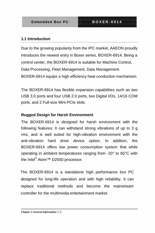
1.1 Introduction
Due to the growing popularity from the IPC market, AAEON proudly
introduces the newest entry in Boxer series, BOXER-6914. Being a
control center, the BOXER-6914 is suitable for Machine Control,
Data Processing, Fleet Management, Data Management.
BOXER-6914 equips a high efficiency heat conduction mechanism.
The BOXER-6914 has flexible expansion capabilities such as two
USB 3.0 ports and four USB 2.0 ports, two Digital I/Os, 14/16 COM
ports, and 2 Full-size Mini-PCIe slots.
Rugged Design for Harsh Environment
The BOXER-6914 is designed for harsh environment with the
following features: It can withstand strong vibrations of up to 3 g
rms, and is well suited for high-vibration environment with the
anti-vibration hard drive device option. In addition, the
BOXER-6914 offers low power consumption system that while
operating in ambient temperatures ranging from -20° to 65°C with
the Intel® Atom™ D2550 processor.
The BOXER-6914 is a standalone high performance box PC
designed for long-life operation and with high reliability. It can
replace traditional methods and become the mainstream
controller for the multimedia entertainment market.
Embedded Box PC B O X E R - 6 9 1 4
Chapter 1 General Information 1-3
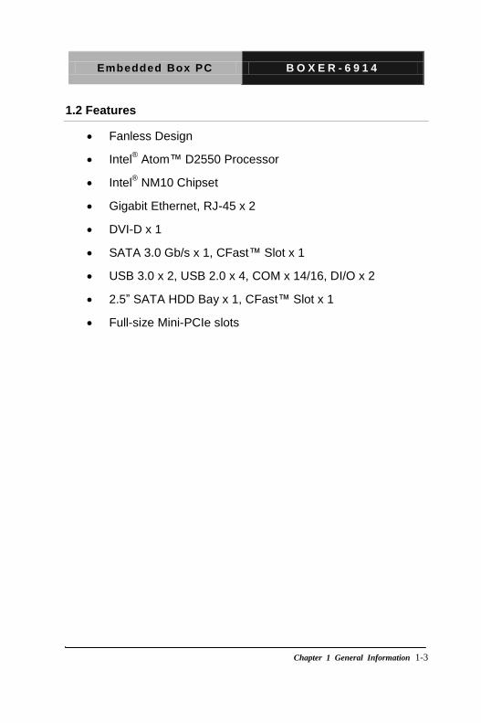
1.2 Features
Fanless Design
Intel® Atom™ D2550 Processor
Intel® NM10 Chipset
Gigabit Ethernet, RJ-45 x 2
DVI-D x 1
SATA 3.0 Gb/s x 1, CFast™ Slot x 1
USB 3.0 x 2, USB 2.0 x 4, COM x 14/16, DI/O x 2
2.5” SATA HDD Bay x 1, CFast™ Slot x 1
Full-size Mini-PCIe slots
Embedded Box PC B O X E R - 6 9 1 4
Chapter 1 General Information 1-4
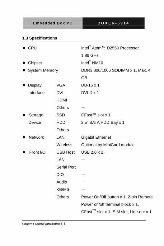
1.3 Specifications
CPU Intel® Atom™ D2550 Processor,
1.86 GHz
Chipset Intel® NM10
System Memory DDR3 800/1066 SODIMM x 1, Max. 4
GB
Display
Interface
VGA DB-15 x 1
DVI DVI-D x 1
HDMI -
Others -
Storage
Device
SSD CFast™ slot x 1
HDD 2.5” SATA HDD Bay x 1
Others -
Network LAN Gigabit Ethernet
Wireless Optional by MiniCard module
Front I/O USB Host USB 2.0 x 2
LAN -
Serial Port -
DIO -
Audio -
KB/MS -
Others Power On/Off button x 1, 2-pin Remote
Power on/off terminal block x 1,
CFastTM
slot x 1, SIM slot, Line-out x 1
Embedded Box PC B O X E R - 6 9 1 4
Chapter 1 General Information 1-5
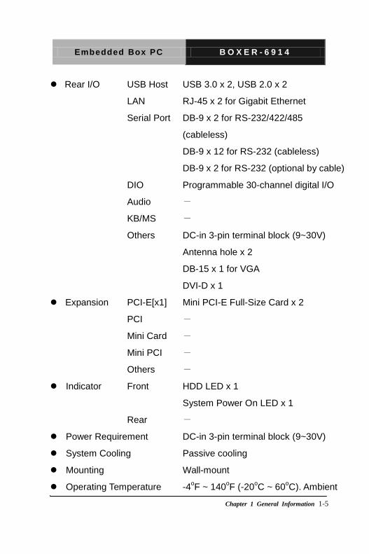
Rear I/O USB Host USB 3.0 x 2, USB 2.0 x 2
LAN RJ-45 x 2 for Gigabit Ethernet
Serial Port DB-9 x 2 for RS-232/422/485
(cableless)
DB-9 x 12 for RS-232 (cableless)
DB-9 x 2 for RS-232 (optional by cable)
DIO Programmable 30-channel digital I/O
Audio -
KB/MS -
Others DC-in 3-pin terminal block (9~30V)
Antenna hole x 2
DB-15 x 1 for VGA
DVI-D x 1
Expansion PCI-E[x1] Mini PCI-E Full-Size Card x 2
PCI -
Mini Card -
Mini PCI -
Others -
Indicator Front HDD LED x 1
System Power On LED x 1
Rear -
Power Requirement DC-in 3-pin terminal block (9~30V)
System Cooling Passive cooling
Mounting Wall-mount
Operating Temperature -4oF ~ 140
oF (-20
oC ~ 60
oC). Ambient
Embedded Box PC B O X E R - 6 9 1 4
Chapter 1 General Information 1-6
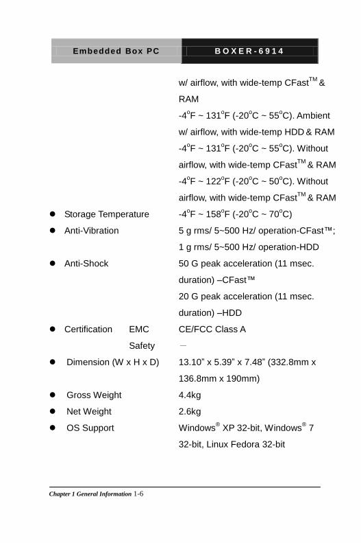
w/ airflow, with wide-temp CFastTM
&
RAM
-4oF ~ 131
oF (-20
oC ~ 55
oC). Ambient
w/ airflow, with wide-temp HDD & RAM
-4oF ~ 131
oF (-20
oC ~ 55
oC). Without
airflow, with wide-temp CFastTM
& RAM
-4oF ~ 122
oF (-20
oC ~ 50
oC). Without
airflow, with wide-temp CFastTM
& RAM
Storage Temperature -4oF ~ 158
oF (-20
oC ~ 70
oC)
Anti-Vibration 5 g rms/ 5~500 Hz/ operation-CFast™;
1 g rms/ 5~500 Hz/ operation-HDD
Anti-Shock 50 G peak acceleration (11 msec.
duration) –CFast™
20 G peak acceleration (11 msec.
duration) –HDD
Certification EMC CE/FCC Class A
Safety -
Dimension (W x H x D) 13.10” x 5.39” x 7.48” (332.8mm x
136.8mm x 190mm)
Gross Weight 4.4kg
Net Weight 2.6kg
OS Support Windows® XP 32-bit, Windows
® 7
32-bit, Linux Fedora 32-bit
Embedded Box PC B O X E R - 6 9 1 4
Chapter 1 General Information 1-7
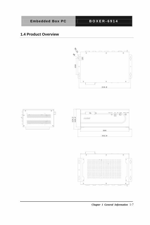
1.4 Product Overview
BOXER- 6 9 1 4
UNITS:m m
3 3 2 ,8
3 0 0
12
4,2
11
0,2
1 9 0
1 1 ,9
3 1 6 ,8
10
0R
2,2
5
R5
20
COM5 COM7 COM9 COM11
COM6 COM8 COM10 COM12
COM1 COM3 COM13
COM2 COM4 COM14
COM16 COM15
DIO
DIODVI
VGA USB/LAN
F.G.
DC-IN 9~30V
F.G . - +AUDIO OUT HDD REMOTE POWERPOWERUSB
Embedded Box PC B O X E R - 6 9 1 4
Chapter 1 General Information 1-8
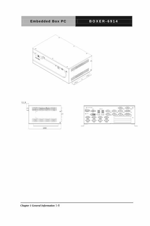
BOXER- 6 9 1 4
UNITS:m m
3 3 2 ,8
3 0 0
12
4,2
11
0,2
1 9 0
1 1 ,9
3 1 6 ,8
10
0
R2
,25
R5
20
COM5 COM7 COM9 COM11
COM6 COM8 COM10 COM12
COM1 COM3 COM13
COM2 COM4 COM14
COM16 COM15
DIO
DIODVI
VGA USB/LAN
F.G.
DC-IN 9~30V
F.G . - +AUDIO OUT HDD REMOTE POWERPOWERUSB
Embedded Box PC B O X E R - 6 9 1 4
Quick Installation
Guide
Chapter
2
Chapter 2 Hardware Installation 2-1
Embedded Box PC B O X E R - 6 9 1 4
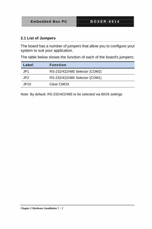
2.1 List of Jumpers
The board has a number of jumpers that allow you to configure your system to suit your application.
The table below shows the function of each of the board's jumpers:
Label Function
JP1 RS-232/422/485 Selector (COM2)
JP2 RS-232/422/485 Selector (COM1)
JP10 Clear CMOS
Note: By default, RS-232/422/485 to be selected via BIOS settings
Chapter 2 Hardware Installation 2 - 2
Embedded Box PC B O X E R - 6 9 1 4
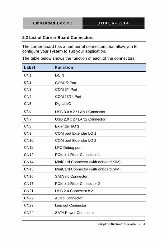
2.2 List of Carrier Board Connectors
The carrier board has a number of connectors that allow you to configure your system to suit your application.
The table below shows the function of each of the connectors:
Label Function
CN1 DCIN
CN2 COM1/2 Port
CN3 COM 3/4 Port
CN4 COM 13/14 Port
CN5 Digital I/O
CN6 USB 3.0 x 2 / LAN1 Connector
CN7 USB 2.0 x 2 / LAN2 Connector
CN8 Extender I/O 3
CN9 COM port Extender I/O 1
CN10 COM port Extender I/O 2
CN11 LPC Debug port
CN12 PCIe x 1 Riser Connector 1
CN14 MiniCard Connector (with onboard SIM)
CN15 MiniCard Connector (with onboard SIM)
CN16 SATA 2.0 Connector
CN17 PCIe x 1 Riser Connector 2
CN21 USB 2.0 Connector x 2
CN22 Audio Connector
CN23 Line out Connector
CN24 SATA Power Connector
Chapter 2 Hardware Installation 2 - 3
Embedded Box PC B O X E R - 6 9 1 4
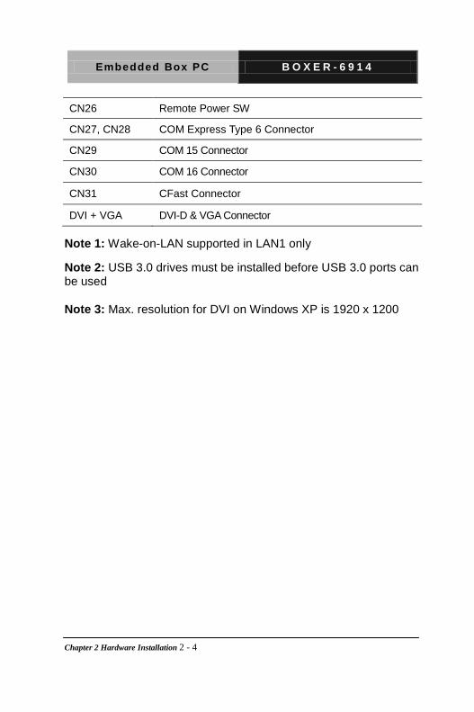
CN26 Remote Power SW
CN27, CN28 COM Express Type 6 Connector
CN29 COM 15 Connector
CN30 COM 16 Connector
CN31 CFast Connector
DVI + VGA DVI-D & VGA Connector
Note 1: Wake-on-LAN supported in LAN1 only
Note 2: USB 3.0 drives must be installed before USB 3.0 ports can be used
Note 3: Max. resolution for DVI on Windows XP is 1920 x 1200
Chapter 2 Hardware Installation 2 - 4
Embedded Box PC B O X E R - 6 9 1 4
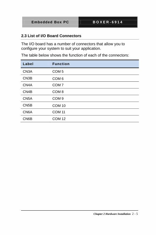
2.3 List of I/O Board Connectors
The I/O board has a number of connectors that allow you to configure your system to suit your application.
The table below shows the function of each of the connectors:
Label Function
CN3A COM 5
CN3B COM 6
CN4A COM 7
CN4B COM 8
CN5A COM 9
CN5B COM 10
CN6A COM 11
CN6B COM 12
Chapter 2 Hardware Installation 2 - 5

Embedded Box PC B O X E R - 6 9 1 4
2.4 Setting Jumpers
You configure your card to match the needs of your application by setting jumpers. A jumper is the simplest kind of electric switch. It consists of two metal pins and a small metal clip (often protected by a plastic cover) that slides over the pins to connect them. To “close” a jumper you connect the pins with the clip.
To “open” a jumper you remove the clip. Sometimes a jumper will have three pins, labeled 1, 2 and 3. In this case you would connect either pins 1 and 2 or 2 and 3.
1 2 3
Open Closed Closed 2-3
A pair of needle-nose pliers may be helpful when working with jumpers.
If you have any doubts about the best hardware configuration for your application, contact your local distributor or sales representative before you make any change.
In general, you simply need a standard cable to make most connections.
Chapter 2 Hardware Installation 2 - 6
Embedded Box PC B O X E R - 6 9 1 4
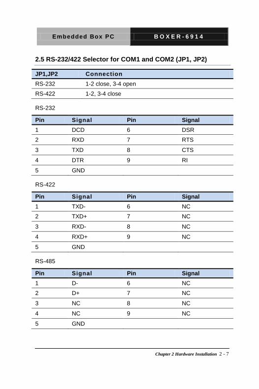
2.5 RS-232/422 Selector for COM1 and COM2 (JP1, JP2)
JP1,JP2 Connection RS-232 1-2 close, 3-4 open
RS-422 1-2, 3-4 close
RS-232
Pin Signal Pin Signal 1 DCD 6 DSR
2 RXD 7 RTS
3 TXD 8 CTS
4 DTR 9 RI
5 GND
RS-422
Pin Signal Pin Signal 1 TXD- 6 NC
2 TXD+ 7 NC
3 RXD- 8 NC
4 RXD+ 9 NC
5 GND
RS-485
Pin Signal Pin Signal 1 D- 6 NC
2 D+ 7 NC
3 NC 8 NC
4 NC 9 NC
5 GND
Chapter 2 Hardware Installation 2 - 7

Embedded Box PC B O X E R - 6 9 1 4
2.6 Clear CMOS (JP10)
JP10 Function
1-2 Normal (Default)
2-3 Clear CMOS
2.7 Digital I/O (CN5 – Carrier Board)
CN5A (Carrier board)
Pin Signal Pin Signal
1 DIO0-0 9 DIO1-0
2 DIO0-1 10 DIO1-1
3 DIO0-2 11 DIO1-2
4 DIO0-3 12 DIO1-3
5 DIO0-4 13 DIO1-4
6 DIO0-5 14 DIO1-5
7 DIO0-6 15 DIO1-6
8 DIO0-7
CN5B (Carrier board)
Pin Signal Pin Signal
1 DIO1-7 9 DIO2-7
2 DIO2-0 10 DIO3-0
3 DIO2-1 11 DIO3-1
4 DIO2-2 12 DIO3-2
5 DIO2-3 13 DIO3-3
6 DIO2-4 14 DIO3-4
7 DIO2-5 15 DIO3-5
8 DIO2-6
Chapter 2 Hardware Installation 2 - 8
Embedded Box PC B O X E R - 6 9 1 4
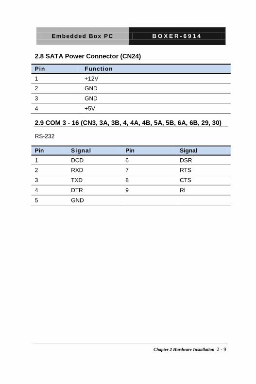
2.8 SATA Power Connector (CN24)
Pin Function
1 +12V
2 GND
3 GND
4 +5V
2.9 COM 3 - 16 (CN3, 3A, 3B, 4, 4A, 4B, 5A, 5B, 6A, 6B, 29, 30)
RS-232
Pin Signal Pin Signal 1 DCD 6 DSR
2 RXD 7 RTS
3 TXD 8 CTS
4 DTR 9 RI
5 GND
Chapter 2 Hardware Installation 2 - 9

Embedded Box PC B O X E R - 6 9 1 4
AMI BIOS Setup
Chapter
3
Chapter 3 AMI BIOS Setup 3-1
Embedded Box PC B O X E R - 6 9 1 4
3.1 System Test and Initialization
These routines test and initialize board hardware. If the routines
encounter an error during the tests, you will either hear a few short
beeps or see an error message on the screen. There are two kinds
of errors: fatal and non-fatal. The system can usually continue the
boot up sequence with non-fatal errors.
System configuration verification
These routines check the current system configuration stored in the
CMOS memory and BIOS NVRAM. If system configuration is not
found or system configuration data error is detected, system will
load optimized default and re-boot with this default system
configuration automatically.
There are four situations in which you will need to setup system
configuration:
1. You are starting your system for the first time
2. You have changed the hardware attached to your system
3. The system configuration is reset by Clear-CMOS jumper
4. The CMOS memory has lost power and the configuration
information has been erased.
The BOXER-6914 CMOS memory has an integral lithium battery
backup for data retention. However, you will need to replace the
complete unit when it finally runs down.
Chapter 3 AMI BIOS Setup 3-2

Embedded Box PC B O X E R - 6 9 1 4
3.2 AMI BIOS Setup
AMI BIOS ROM has a built-in Setup program that allows users to
modify the basic system configuration. This type of information is
stored in battery-backed CMOS RAM and BIOS NVRAM so that it
retains the Setup information when the power is turned off.
Entering Setup
Power on the computer and press <Del>or <F2> immediately. This
will allow you to enter Setup.
Main
Set the date, use tab to switch between date elements.
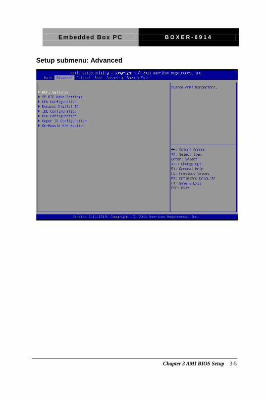
Advanced
Enable disable boot option for legacy network devices.
Chipset
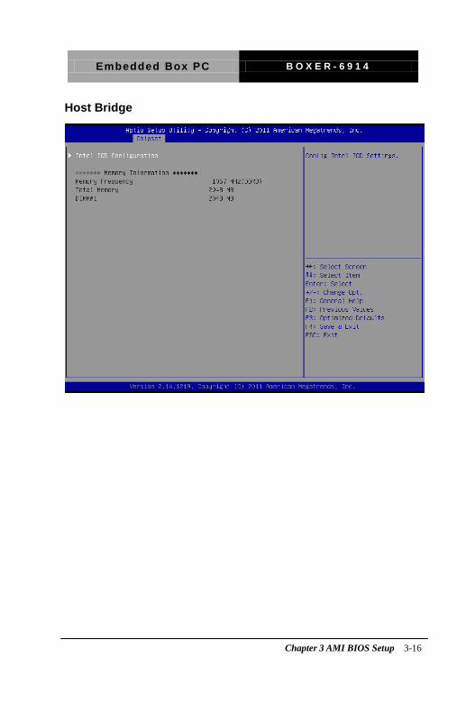
Host bridge parameters.
Boot
Enables/disable quiet boot option.
Security
Set setup administrator password.
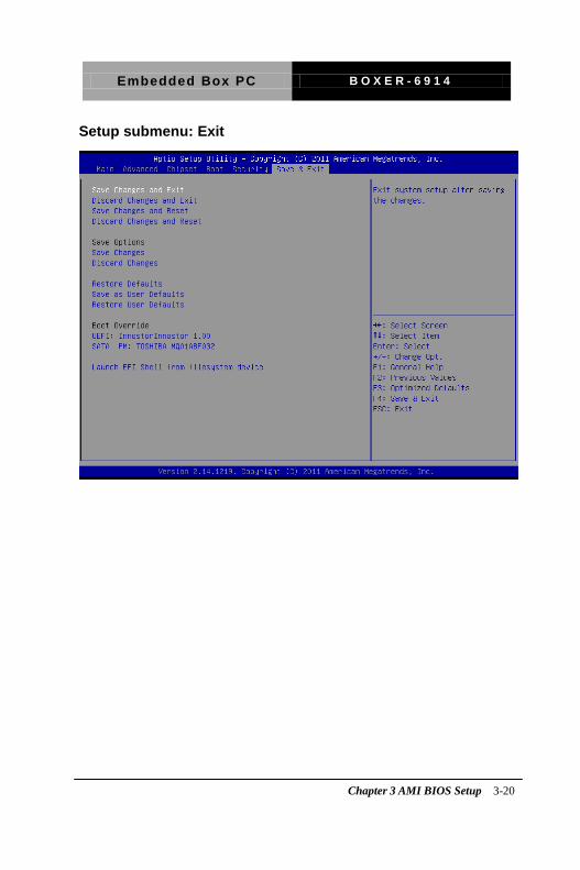
Save & Exit
Exit system setup after saving the changes.
Chapter 3 AMI BIOS Setup 3-3

Embedded Box PC B O X E R - 6 9 1 4
Setup Menu
Setup submenu: Main
Chapter 3 AMI BIOS Setup 3-4
Embedded Box PC B O X E R - 6 9 1 4
Setup submenu: Advanced
Chapter 3 AMI BIOS Setup 3-5

Embedded Box PC B O X E R - 6 9 1 4
CPU Configuration
Options summary: Hyper-Threading Disabled
Enabled Optimal Default, Failsafe Default
Chapter 3 AMI BIOS Setup 3-6

Embedded Box PC B O X E R - 6 9 1 4
IDE Configuration (IDE)
Options summary:
SATA Controllers Enable Optimal Default, Failsafe Default Disable
En/Disable SATA Controller
SATA Mode IDE Optimal Default, Failsafe Default AHCI
Chapter 3 AMI BIOS Setup 3-7

Embedded Box PC B O X E R - 6 9 1 4
USB Configuration
Options summary: Legacy USB Support Enable Optimal Default, Failsafe Default
Disable
Chapter 3 AMI BIOS Setup 3-8
Embedded Box PC B O X E R - 6 9 1 4
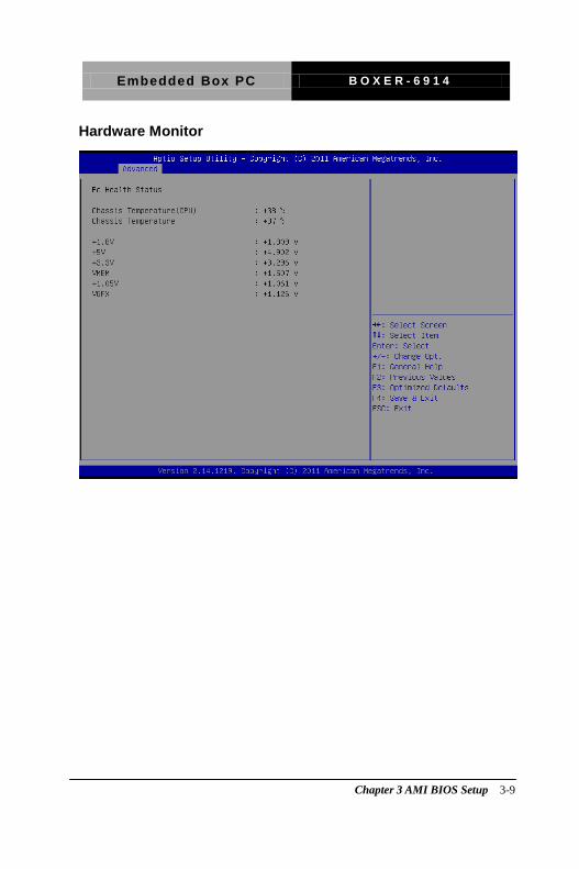
Hardware Monitor
Chapter 3 AMI BIOS Setup 3-9
Embedded Box PC B O X E R - 6 9 1 4
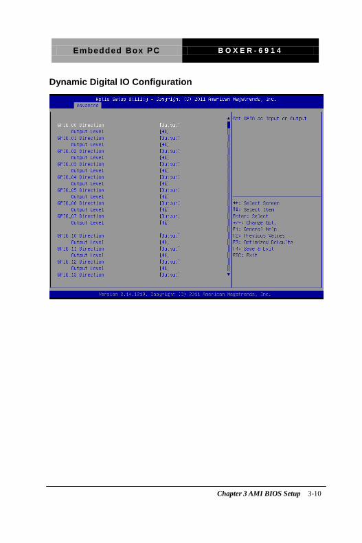
Dynamic Digital IO Configuration
Chapter 3 AMI BIOS Setup 3-10
Embedded Box PC B O X E R - 6 9 1 4
Chapter 3 AMI BIOS Setup 3-11
Embedded Box PC B O X E R - 6 9 1 4
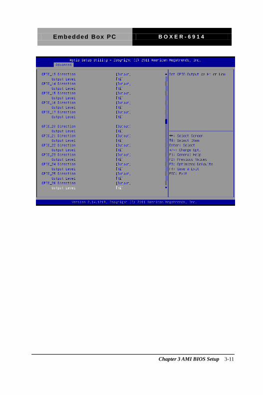
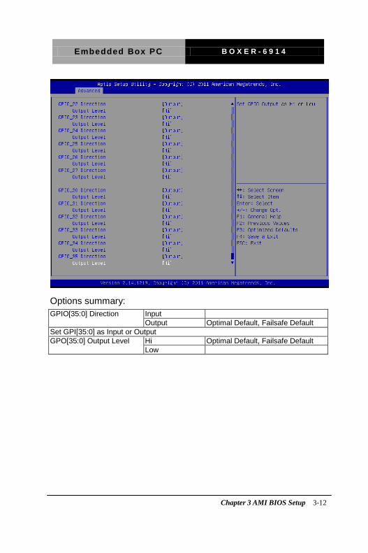
Options summary: GPIO[35:0] Direction Input
Output Optimal Default, Failsafe Default Set GPI[35:0] as Input or Output GPO[35:0] Output Level Hi Optimal Default, Failsafe Default
Low
Chapter 3 AMI BIOS Setup 3-12
Embedded Box PC B O X E R - 6 9 1 4
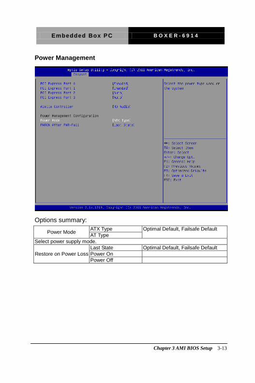
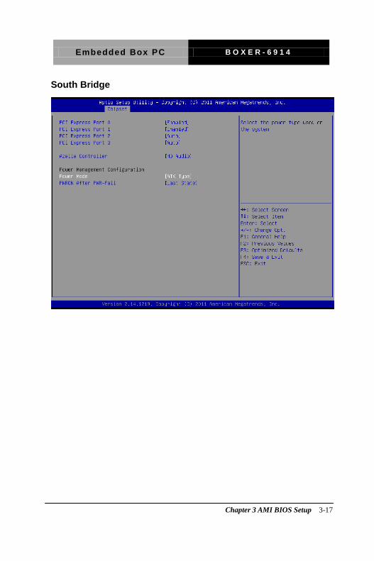
Power Management
Options summary:
Power Mode ATX Type Optimal Default, Failsafe Default AT Type
Select power supply mode.
Restore on Power Loss Last State Optimal Default, Failsafe Default Power On Power Off
Chapter 3 AMI BIOS Setup 3-13
Embedded Box PC B O X E R - 6 9 1 4
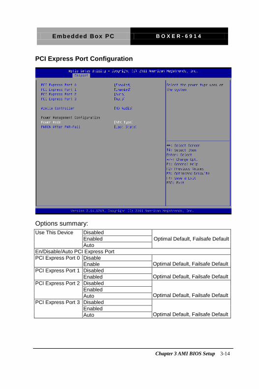
PCI Express Port Configuration
Options summary: Use This Device Disabled
Enabled Optimal Default, Failsafe Default Auto
En/Disable/Auto PCI Express Port PCI Express Port 0 Disable
Optimal Default, Failsafe Default Enable PCI Express Port 1 Disabled
Optimal Default, Failsafe Default Enabled PCI Express Port 2 Disabled
Optimal Default, Failsafe Default
Enabled Auto
PCI Express Port 3 Disabled Optimal Default, Failsafe Default
Enabled Auto
Chapter 3 AMI BIOS Setup 3-14
Embedded Box PC B O X E R - 6 9 1 4
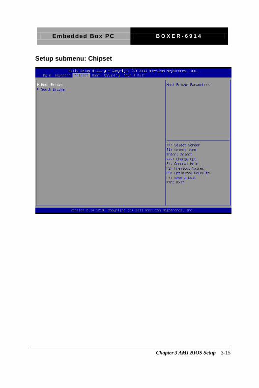
Setup submenu: Chipset
Chapter 3 AMI BIOS Setup 3-15
Embedded Box PC B O X E R - 6 9 1 4
Host Bridge
Chapter 3 AMI BIOS Setup 3-16
Embedded Box PC B O X E R - 6 9 1 4
South Bridge
Chapter 3 AMI BIOS Setup 3-17

Embedded Box PC B O X E R - 6 9 1 4
Security
Change User/Supervisor Password You can install a Supervisor password, and if you install a supervisor password, you can then install a user password. A user password does not provide access to many of the features in the Setup utility. If you highlight these items and press Enter, a dialog box appears which lets you enter a password. You can enter no more than six letters or numbers. Press Enter after you have typed in the password. A second dialog box asks you to retype the password for confirmation. Press Enter after you have retyped it correctly. The password is required at boot time, or when the user enters the Setup utility.
Removing the Password
Highlight this item and type in the current password. At the next dialog
box press Enter to disable password protection.
Chapter 3 AMI BIOS Setup 3-18

Embedded Box PC B O X E R - 6 9 1 4
Setup submenu: Boot
Options summary: Quiet Boot Disabled
Enabled Default En/Disable showing boot logo. Option ROM Messages Force BIOS Default
Keep Current Set display mode for Option ROM Launch On-Module LAN PXE OpROM Disabled Default
Enabled En/Disable Legacy Boot Option
Chapter 3 AMI BIOS Setup 3-19
Embedded Box PC B O X E R - 6 9 1 4
Setup submenu: Exit
Chapter 3 AMI BIOS Setup 3-20

Embedded Box PC B O X E R - 6 9 1 4
Driver Installation
Chapter
4
Chapter 4 Driver Installation 4 -1
Embedded Box PC B O X E R - 6 9 1 4
The BOXER-6914 comes with a driver disk that contains all drivers
and utilities that can help you setup your product.
Insert the disk and the installation guide will start automatically. If it
doesn’t, please follow the sequence below to install the drivers.
Follow the sequence below to install the drivers:
Step 1 – Install Chipset Driver
Step 2 – Install VGA Driver
Step 3 – Install LAN Driver
Step 4 – Install Audio Driver
Step 5 – Install USB 3.0 Driver
Step 6 – Install AHCI Driver
Step 7 – Install F81216 Patch
Step 8 – Install F81512 Driver
Please read following instructions for detailed installations.
Chapter 4 Driver Installation 4 -2
Embedded Box PC B O X E R - 6 9 1 4
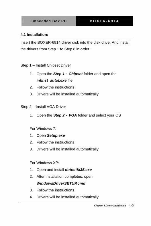
4.1 Installation:
Insert the BOXER-6914 driver disk into the disk drive. And install
the drivers from Step 1 to Step 8 in order.
Step 1 – Install Chipset Driver
1. Open the Step 1 - Chipset folder and open the
infinst_autol.exe file
2. Follow the instructions
3. Drivers will be installed automatically
Step 2 – Install VGA Driver
1. Open the Step 2 - VGA folder and select your OS
For Windows 7:
1. Open Setup.exe
2. Follow the instructions
3. Drivers will be installed automatically
For Windows XP:
1. Open and install dotnetfx35.exe
2. After installation completes, open
WindowsDriverSETUP.cmd
3. Follow the instructions
4. Drivers will be installed automatically
Chapter 4 Driver Installation 4 -3

Embedded Box PC B O X E R - 6 9 1 4
Step 3 – Install LAN Driver
1. Open the Step 3 - LAN folder and select your OS
2. Open the .exe file in the folder
3. Follow the instructions
4. Drivers will be installed automatically
Step 4 – Install Audio Driver
1. Open the Step 4 - AUDIO folder and select your OS
2. Open setup.exe
3. Follow the instructions
4. Drivers will be installed automatically
Step 5 – Install USB3.0 Driver
1. Open the Step 5 – USB3.0 folder and open
RENESAS-USB3-Host-Driver-21160-setup file
2. Follow the instructions
3. Drivers will be installed automatically
Step 6 – Install AHCI Driver
1. Open the Step 6 - AHCI folder and select your OS
2. Open setup.exe
3. Follow the instructions
4. Drivers will be installed automatically
Chapter 4 Driver Installation 4 -4

Embedded Box PC B O X E R - 6 9 1 4
Step 7 – Install F81216 Patch
1. Open the Step 7 – F81216 Patch folder and open the
setup.exe file
2. Follow the instructions
3. Drivers will be installed automatically
Step 8 – Install F81512 Driver
1. Open the Step 8 – F81512 Driver folder and open the
setup.exe file
2. Follow the instructions
3. Drivers will be installed automatically
Chapter 4 Driver Installation 4 -5

Embedded Box PC B O X E R - 6 9 1 4
Programming the
Watchdog Timer
Appendix
A
Appendix A Programming the Watchdog Timer A-1
Embedded Box PC B O X E R - 6 9 1 4
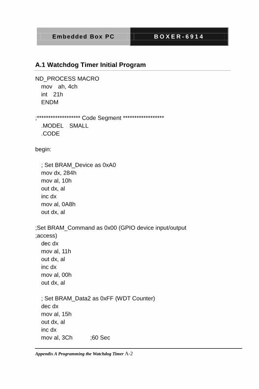
A.1 Watchdog Timer Initial Program
ND_PROCESS MACRO mov ah, 4ch int 21h ENDM ;******************* Code Segment ****************** .MODEL SMALL .CODE begin: ; Set BRAM_Device as 0xA0 mov dx, 284h mov al, 10h out dx, al inc dx mov al, 0A8h out dx, al ;Set BRAM_Command as 0x00 (GPIO device input/output ;access) dec dx mov al, 11h out dx, al inc dx mov al, 00h out dx, al ; Set BRAM_Data2 as 0xFF (WDT Counter) dec dx mov al, 15h out dx, al inc dx mov al, 3Ch ;60 Sec
Appendix A Programming the Watchdog Timer A-2
Embedded Box PC B O X E R - 6 9 1 4
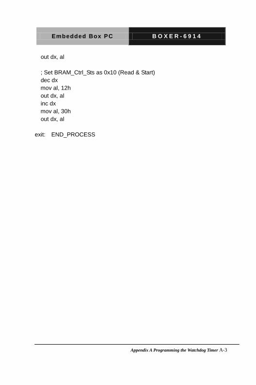
out dx, al ; Set BRAM_Ctrl_Sts as 0x10 (Read & Start) dec dx mov al, 12h out dx, al inc dx mov al, 30h out dx, al exit: END_PROCESS
Appendix A Programming the Watchdog Timer A-3
Embedded Box PC B O X E R - 6 9 1 4
I/O Information
Appendix
B
Appendix B I/O Information B-1

Embedded Box PC B O X E R - 6 9 1 4
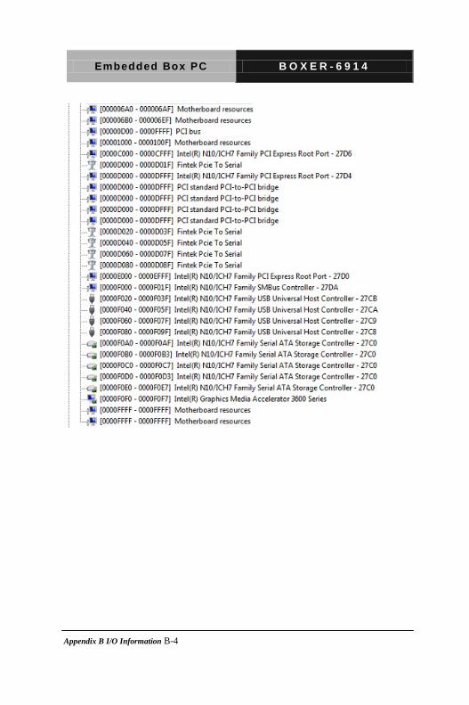
B.1 I/O Address Map
Appendix B I/O Information B-2

Embedded Box PC B O X E R - 6 9 1 4
Appendix B I/O Information B-3
Embedded Box PC B O X E R - 6 9 1 4
Appendix B I/O Information B-4
Embedded Box PC B O X E R - 6 9 1 4
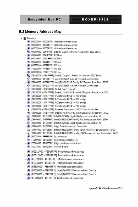
B.2 Memory Address Map
Appendix B I/O Information B-5

Embedded Box PC B O X E R - 6 9 1 4
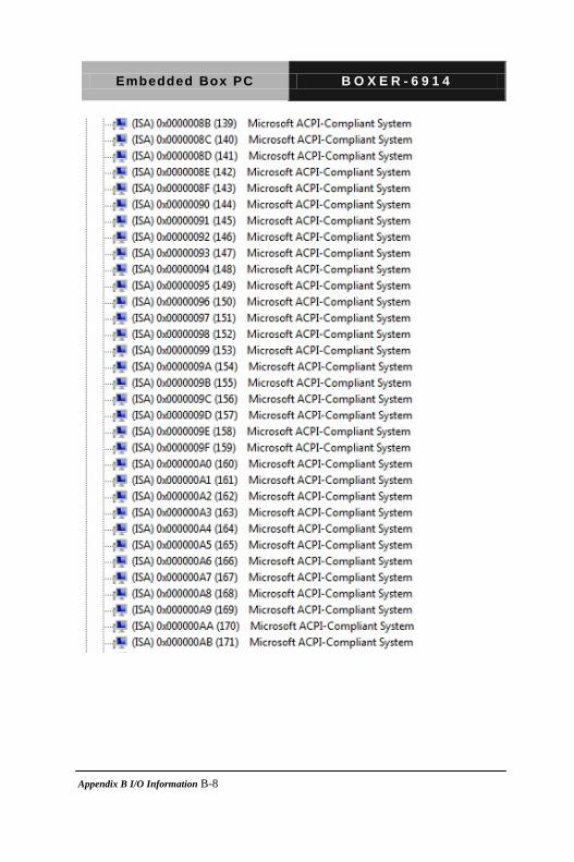
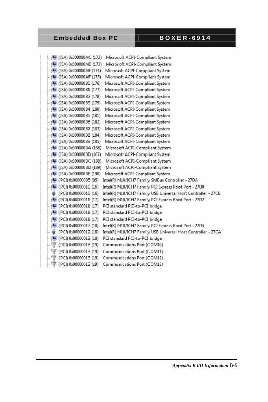
B.3 IRQ Mapping Chart
Appendix B I/O Information B-6

Embedded Box PC B O X E R - 6 9 1 4
Appendix B I/O Information B-7
Embedded Box PC B O X E R - 6 9 1 4
Appendix B I/O Information B-8
Embedded Box PC B O X E R - 6 9 1 4
Appendix B I/O Information B-9
Embedded Box PC B O X E R - 6 9 1 4
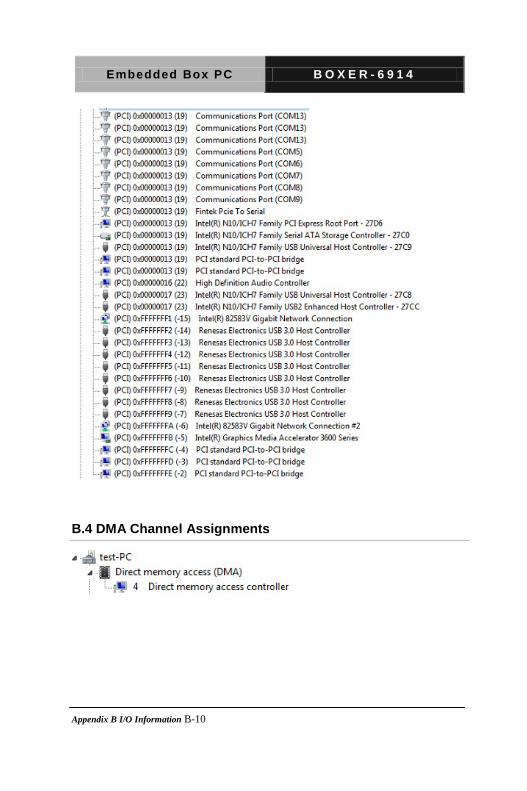
B.4 DMA Channel Assignments
Appendix B I/O Information B-10

Embedded Box PC B O X E R - 6 9 1 4
Programming the Digital I/O
Appendix
C
Appendix C Programming the Digital I/O C-1
Embedded Box PC B O X E R - 6 9 1 4
C.1 DIO Programming
1. General Description
F75113 is a low power general purpose IO chip providing 40 GPIO.
Level or pulse mode can be programmed by registers so all GPIO
can be programmed to logic one, zero, high pulse or low pulse.
GPIO0X~GPIO2X can be programmed to be power LED. F75113
includes two sets of watchdog timer for system reset. Besides, two
power-down modes (Manual or Smart) can be selected to save
power and control the total consumption under 10uA, so F75113
can fit the requirement of mobile device such as PDA or cell phone.
2. Access Interface
The F75113 provides three auto-detected access interfaces, LPC,
SMBus or SPI, to read/write internal registers. In LPC interface, the
default address of Configuration Register I/O port is 2Eh. When
user writes data 10h to LPC configuration register 27h, the address
of Configuration Register I/O port will be 4Eh. In SMBus interface,
Serial Bus address default value is 6Eh (0110_1110). Another SPI
interface only care the least eight bits (LSB) of 24 bits address. SPI
interface write register by 02h instruction (Page Program) and read
register by 03h instruction (Read Data). Also SPI interface
supported byte write/read function.
Besides, the pin 46, 47, 48, 1, 2, 3, 4 are multi-function pins. If user
want to access internal register by LPC interface, the F75113 will
Appendix C Programming the Digital I/O C-2
Embedded Box PC B O X E R - 6 9 1 4
only supported 39 GPIO function and the pin 4 won’t be used for
GPIO function. If user wants to access internal register by SMBus
interface, the pin 48, 1, 2, 3 must be set internal pull-high with 10KΩ.
When user don’t use the pin 4 (GPIO function), the pin will must be
set internal pull-high. In SPI interface, the pin 2, 3 must be set
internal pull-high with 10KΩ. Also, the pin 4 will be selectively set
internal pull-high with 10KΩ by user.
3. Register Description
When users access internal registers by LPC interface, the
configuration register will be used to control the behavior of the
corresponding devices. To configure the register, using the index
port to select the index and then writing data port to alter the
parameters. The default index port and data port are 2Eh and 2Fh
respectively. Write data 10h in index 27h of global control register to
change the default value to 4Eh/4Fh. To enable configuration, the
entry key 50h must be written to the index port. To disable
configuration, write exit key AAh to the index port. Following is an
example to enable configuration and disable configuration by using
debug.
-o 2e 50
-o 2e 50 (enable configuration)
-o 2e aa (disable configuration)
The Following is a register map (total devices) grouped in
hexadecimal address order, which shows a summary of all registers
Appendix C Programming the Digital I/Os C-3

Embedded Box PC B O X E R - 6 9 1 4
and their default value. Please refer each device chapter if you want
more detail information.
Appendix C Programming the Digital I/O C-4
Embedded Box PC B O X E R - 6 9 1 4
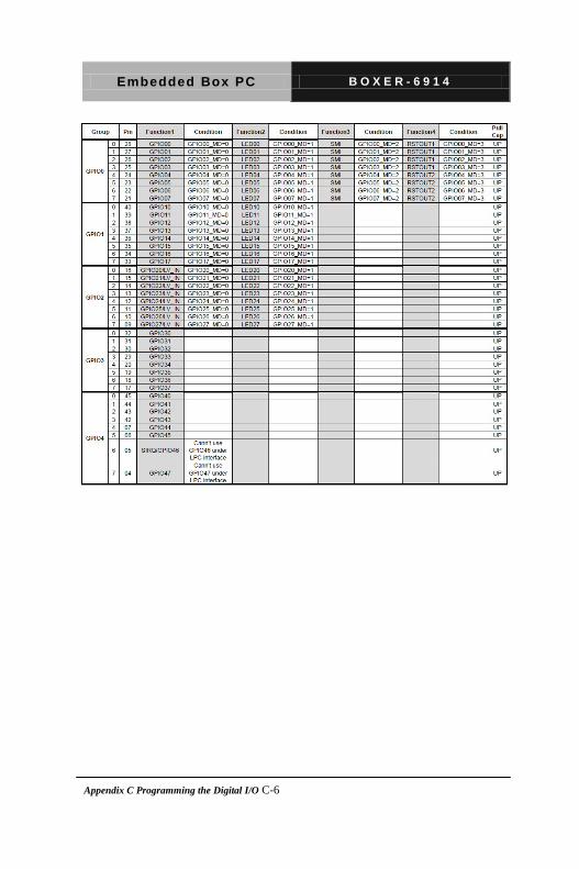
4. GPIO Function
The F75113 with GPIO0X~GPIO4X General Purpose I/O port is
composed of independent I/O pins controlled and controls multi-pin
function by Index 02~06h register. Each of GPIO group has input
capability, output (push-pull and open-drain) capability, internal
pull-up resister with 10KΩ. Also F75113 has GPIO2x groups with
the Low Level Input, LED, SMI and RSTOUT function. Please
check below table how to select the GPIO multi-function pin that
user wants.
Appendix C Programming the Digital I/Os C-5
Embedded Box PC B O X E R - 6 9 1 4
Appendix C Programming the Digital I/O C-6
Embedded Box PC B O X E R - 6 9 1 4
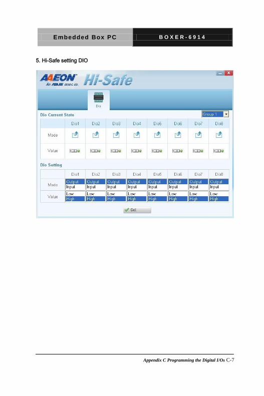
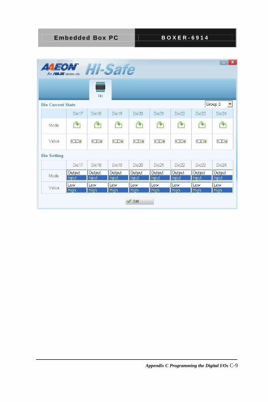
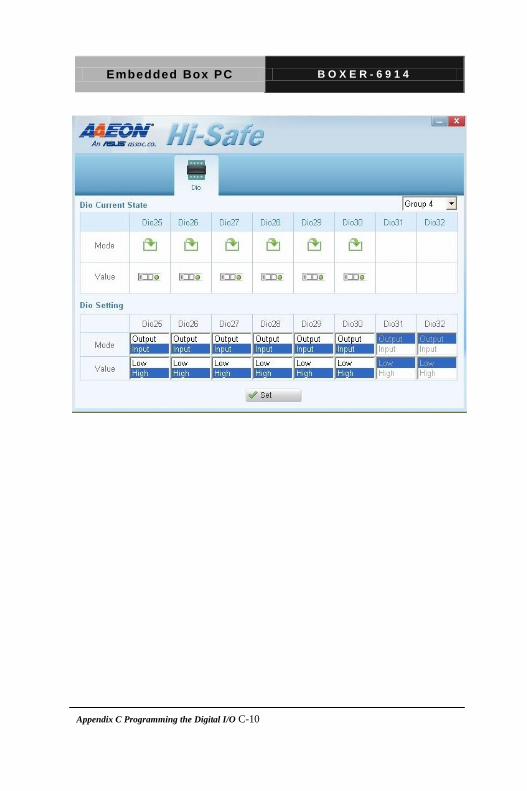
5. Hi-Safe setting DIO
Appendix C Programming the Digital I/Os C-7

Embedded Box PC B O X E R - 6 9 1 4
Appendix C Programming the Digital I/O C-8
Embedded Box PC B O X E R - 6 9 1 4
Appendix C Programming the Digital I/Os C-9
Embedded Box PC B O X E R - 6 9 1 4
Appendix C Programming the Digital I/O C-10


![Boxer Engine[101]](https://img.pdfslide.us/doc/110x75/552722bd4a795973118b4635/boxer-engine101.jpg)