Embed Size (px)
Citation preview
Rev. 2010-08-16130R0195 MG12J202
*MG14B102*
Embedded BACnetOperating Instructions
August 2010
TR200
BAS-SVX35A-EN
Trane has a policy of continuous product and product data improvement and reserves the right to change design and specifications without notice.
www.trane.com
For more information, contact your local Trane office or e-mail us at [email protected]
Literature order number BAS-SVX35A-EN
Date August 2010
Substitutes
Table of Contents
Safety 2
Copyright, Limitation of Liability and Revision Rights 2
Before Commencing Repair Work 4
Special Conditions 5
Introduction 6
How to Install 8
The BACnet Interface 8
Switches S201, S202, and S801 10
Bus Cabling 12
How to Configure the System 13
Configuring BACnet 13
Example of a simple setup of BACnet 14
How to Control the Frequency Converter 15
Network Frequency Converter Control Inputs and -Outputs 16
Drive Feedback to Network 21
BIBBs 21
Parameters 23
Parameter Overview 23
Parameter Description 24
Troubleshooting 31
Alarm, Warning and Extended Status Word 31
Alarm Words 32
Warning Words 33
Index 34
TR200 Embedded BACnet Operating Instructions 1

Safety
Copyright, Limitation of Liability and Revision Rights This publication contains information proprietary to Trane. By accepting and using this manual the user agrees
that the information contained herein will be used solely for operating equipment from Trane or equipment
from other vendors provided that such equipment is intended for communication with Trane equipment over
a serial communication link. This publication is protected under the Copyright laws of most countries.
Trane does not warrant that a software program produced according to the guidelines provided in this manual
will function properly in every physical, hardware or software environment.
Although Trane has tested and reviewed the documentation within this manual, Trane makes no warranty or
representation, neither expressed nor implied, with respect to this documentation, including its quality, per-
formance, or fitness for a particular purpose.
In no event shall Trane be liable for direct, indirect, special, incidental, or consequential damages arising out of
the use, or the inability to use information contained in this manual, even if advised of the possibility of such
damages. In particular, Trane is not responsible for any costs, including but not limited to those incurred as a
result of lost profits or revenue, loss or damage of equipment, loss of computer programs, loss of data, the costs
to substitute these, or any claims by third parties.
Trane reserves the right to revise this publication at any time and to make changes to its contents without prior
notice or any obligation to notify former or present users of such revisions or changes.
2 TR200 Embedded BACnet Operating Instructions
Warnings, Cautions and NoticesNote that warnings, cautions and notices appear at appropriate intervals throughout this manual. Warnings are
provide to alert installing contractors to potential hazards that could result in personal injury or death. Cautions
are designed to alert personnel to hazardous situations that could result in personal injury, while notices indicate
a situation that could result in equipment or property-damage-only accidents.
Your personal safety and the proper operation of this machine depend upon the strict observance of these
precautions.
Warnings, Cautions and Notices appear at appropriate sections throughout this literature. Read these carefully.
WARNINGIndicates a potentially hazardous situation which, if not avoided, could result in death or serious injury.
CAUTIONIndicates a potentially hazardous situation which, if not avoided, could result in minor or moderate injury. It could alsobe used to alert against unsafe practices.
NOTICEIndicates a situation that could result in equipment or property-damage only accidents.
Note
Indicates something important to be noted by the reader.
✮ Indicates default setting
Safety
TR200 Embedded BACnet Operating Instructions 3
Safety Note
WARNINGFailure to follow instructions below could result in death or serious injury.
Safety Regulations
1. The frequency converter must be disconnected from mains if repair work is to be carried out. Check that
the mains supply has been disconnected and that the necessary time has passed before removing motor
and mains plugs.
2. The [STOP/RESET] key on the keypad of the frequency converter does not disconnect the equipment from
mains and is thus not to be used as a safety switch.
3. Correct protective earthing of the equipment must be established, the user must be protected against supply
voltage, and the motor must be protected against overload in accordance with applicable national and local
regulations.
4. The earth leakage currents are higher than 3.5 mA.
5. Protection against motor overload is set by par. 1-90 Motor Thermal Protection. If this function is desired,
set par. 1-90 Motor Thermal Protection to data value [ETR trip] (default value) or data value [ETR warning].
Note: The function is initialized at 1.16 x rated motor current and rated motor frequency. For the North
American market: The ETR functions provide class 20 motor overload protection in accordance with NEC.
6. Do not remove the plugs for the motor and mains supply while the frequency converter is connected to
mains. Check that the mains supply has been disconnected and that the necessary time has passed before
removing motor and mains plugs.
7. Please note that the frequency converter has more voltage inputs than L1, L2 and L3, when load sharing
(linking of DC intermediate circuit) and external 24 Vdc have been installed. Check that all voltage inputs
have been disconnected and that the necessary time has passed before commencing repair work.
WARNINGWarning against Unintended Start
1. The motor can be brought to a stop by means of digital commands, bus commands, references or a local stop,while the frequency converter is connected to mains. If personal safety considerations make it necessary to ensurethat no unintended start occurs, these stop functions are not sufficient.
2. While parameters are being changed, the motor may start. Consequently, the stop key [STOP/RESET] must alwaysbe activated; following which data can be modified.
3. A motor that has been stopped may start if faults occur in the electronics of the frequency converter, or if atemporary overload or a fault in the supply mains or the motor connection ceases.
Consequently, disconnect all electric power, including remote disconnects before servicing. Follow proper lockout/tagout procedures to ensure the power can not be inadvertently energized. Failure to follow recommendations couldresult in death or serious injury.
Before Commencing Repair Work
WARNINGHazardous Voltage!
1. Disconnect the frequency converter from mains
2. Disconnect DC bus terminals 88 and 89
3. Wait at least the time mentioned in section General Warning above
4. Remove motor cable
Failure to follow recommendations could result in death or serious injury.
Safety
4 TR200 Embedded BACnet Operating Instructions
Special ConditionsElectrical ratings:
The rating indicated on the nameplate of the frequency converter is based on a typical 3-phase mains power
supply, within the specified voltage, current and temperature range, which is expected to be used in most ap-
plications.
The frequency converters also support other special applications, which affect the electrical ratings of the fre-
quency converter.
Special conditions which affect the electrical ratings might be:
• Single phase applications
• High temperature applications which require de-rating of the electrical ratings
• Marine applications with more severe environmental conditions.
Other applications might also affect the electrical ratings.
Consult the relevant sections in this manual and in the TR200 Design Guide for information about the electrical
ratings.
Installation requirements:
The overall electrical safety of the frequency converter requires special installation considerations regarding:
• Fuses and circuit breakers for over-current and short-circuit protection
• Selection of power cables (mains, motor, brake, loadsharing and relay)
• Grid configuration (grounded delta transformer leg, IT,TN, etc.)
• Safety of low-voltage ports (PELV conditions).
Consult the relevant clauses in these instructions and in the TR200 Design Guide for information about the
installation requirements.
Safety
TR200 Embedded BACnet Operating Instructions 5
Introduction
About this ManualFirst time users can obtain the most essential information for quick installation and set-up in these chapters:
Introduction
How to Install
How to Configure the System
For more detailed information including the full range of set-up options and diagnosis tools please refer to the
chapters:
How to Control the Frequency Converter
Parameters
Troubleshooting
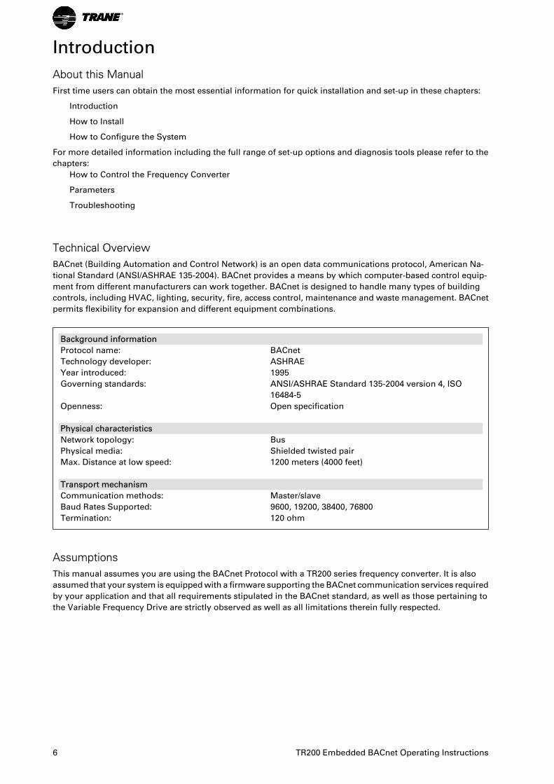
Technical OverviewBACnet (Building Automation and Control Network) is an open data communications protocol, American Na-
tional Standard (ANSI/ASHRAE 135-2004). BACnet provides a means by which computer-based control equip-
ment from different manufacturers can work together. BACnet is designed to handle many types of building
controls, including HVAC, lighting, security, fire, access control, maintenance and waste management. BACnet
permits flexibility for expansion and different equipment combinations.
Background information
Protocol name: BACnet
Technology developer: ASHRAE
Year introduced: 1995
Governing standards: ANSI/ASHRAE Standard 135-2004 version 4, ISO
16484-5
Openness: Open specification
Physical characteristics
Network topology: Bus
Physical media: Shielded twisted pair
Max. Distance at low speed: 1200 meters (4000 feet)
Transport mechanism
Communication methods: Master/slave
Baud Rates Supported: 9600, 19200, 38400, 76800
Termination: 120 ohm
AssumptionsThis manual assumes you are using the BACnet Protocol with a TR200 series frequency converter. It is also
assumed that your system is equipped with a firmware supporting the BACnet communication services required
by your application and that all requirements stipulated in the BACnet standard, as well as those pertaining to
the Variable Frequency Drive are strictly observed as well as all limitations therein fully respected.
6 TR200 Embedded BACnet Operating Instructions
Background KnowledgeThe Trane implementation of the BACnet Protocol is designed to communicate with any system complying with
the BACnet MS/TP standard. Familiarity with the PC, BMS or PLC used as a master in the system is assumed.
Issues regarding hardware or software produced by other manufacturers are beyond the scope of this manual
and are not the responsibility of Trane.
If you have questions regarding set-up of master-to-master communication or communication to a non-Trane
slave, please consult the appropriate manuals.
Available Literature for TR200
- Operating Instructions BAS-SVX19 provide the necessary information for getting the drive up and running.
- Operating Instructions TR200 High Power BAS-SVX21
- Design Guide BAS-SVX23 entails all technical information about the drive and customer design and appli-
cations.
- Programming Guide BAS-SVP04 provides information on how to programme and includes complete pa-
rameter descriptions.
x = Revision number
yy = Language code
Trane technical literature is available in print from your local Trane Sales Office or online at:
www.trane.com/vfd
Abbreviations
ACI Acyclical Control Interval
AOC Application Orientated Controller
AV Analog Variable
BMS Building Management System
BV Binary Variable
CAN Controller Area Network
CTW Control Word
EEPROM Electrical Erasable Programmable Read Only Memory
EIA Electronic Industries Association: Specifies of the EIA Standard RS 485-A
EMC Electromagnetic Compatibility
IND Sub index
I/O Input/Output
ISO International Standards Organization
LCD Liquid Crystal Display
LCP Local Control Panel
LED Light Emitting Diode
MAV Main Actual Value
MRV Main Reference Value
PC Personal Computer
PCD Process Data
PDU Protocol Data Unit
PELV Protected Extra Low Voltage
PLC Programmable Logic Control
PNU Parameter Number
PVA Parameter Value
RC Request/Response Characteristics
STW Status Word
Introduction
TR200 Embedded BACnet Operating Instructions 7
How to Install
The BACnet Interface
Cabling
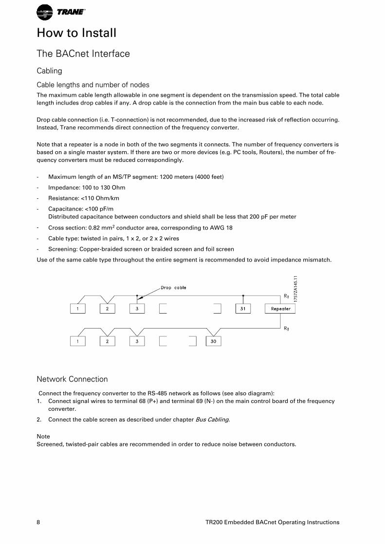
Cable lengths and number of nodesThe maximum cable length allowable in one segment is dependent on the transmission speed. The total cable
length includes drop cables if any. A drop cable is the connection from the main bus cable to each node.
Drop cable connection (i.e. T-connection) is not recommended, due to the increased risk of reflection occurring.
Instead, Trane recommends direct connection of the frequency converter.
Note that a repeater is a node in both of the two segments it connects. The number of frequency converters is
based on a single master system. If there are two or more devices (e.g. PC tools, Routers), the number of fre-
quency converters must be reduced correspondingly.
- Maximum length of an MS/TP segment: 1200 meters (4000 feet)
- Impedance: 100 to 130 Ohm
- Resistance: <110 Ohm/km
- Capacitance: <100 pF/m
Distributed capacitance between conductors and shield shall be less that 200 pF per meter
- Cross section: 0.82 mm2 conductor area, corresponding to AWG 18
- Cable type: twisted in pairs, 1 x 2, or 2 x 2 wires
- Screening: Copper-braided screen or braided screen and foil screen
Use of the same cable type throughout the entire segment is recommended to avoid impedance mismatch.
1757
ZA14
5.11
Network Connection
Connect the frequency converter to the RS-485 network as follows (see also diagram):
1. Connect signal wires to terminal 68 (P+) and terminal 69 (N-) on the main control board of the frequency
converter.
2. Connect the cable screen as described under chapter Bus Cabling.
Note
Screened, twisted-pair cables are recommended in order to reduce noise between conductors.
8 TR200 Embedded BACnet Operating Instructions
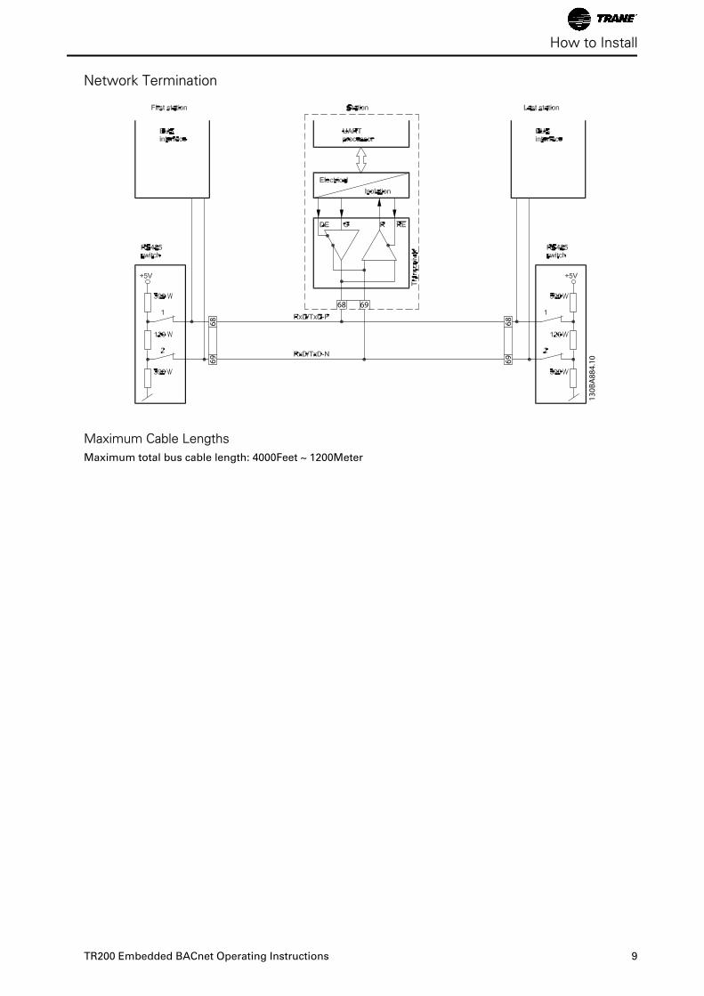
Network Termination
Maximum Cable LengthsMaximum total bus cable length: 4000Feet ~ 1200Meter
How to Install
TR200 Embedded BACnet Operating Instructions 9
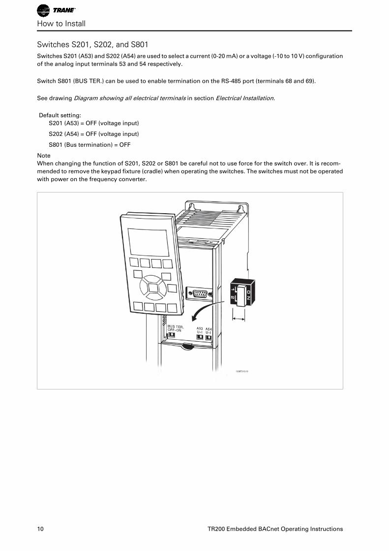
Switches S201, S202, and S801 Switches S201 (A53) and S202 (A54) are used to select a current (0-20 mA) or a voltage (-10 to 10 V) configuration
of the analog input terminals 53 and 54 respectively.
Switch S801 (BUS TER.) can be used to enable termination on the RS-485 port (terminals 68 and 69).
See drawing Diagram showing all electrical terminals in section Electrical Installation.
Default setting:
S201 (A53) = OFF (voltage input)
S202 (A54) = OFF (voltage input)
S801 (Bus termination) = OFF
Note
When changing the function of S201, S202 or S801 be careful not to use force for the switch over. It is recom-
mended to remove the keypad fixture (cradle) when operating the switches. The switches must not be operated
with power on the frequency converter.
130BT310.10
How to Install
10 TR200 Embedded BACnet Operating Instructions
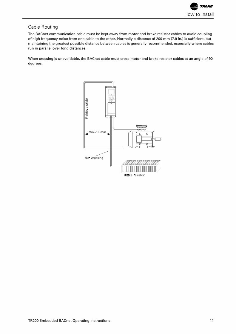
Cable RoutingThe BACnet communication cable must be kept away from motor and brake resistor cables to avoid coupling
of high frequency noise from one cable to the other. Normally a distance of 200 mm (7.9 in.) is sufficient, but
maintaining the greatest possible distance between cables is generally recommended, especially where cables
run in parallel over long distances.
When crossing is unavoidable, the BACnet cable must cross motor and brake resistor cables at an angle of 90
degrees.
How to Install
TR200 Embedded BACnet Operating Instructions 11
Bus Cabling
EMC PrecautionsThe following EMC precautions are recommended to achieve interference-free operation of the BACnet network.
Additional EMC information is available in the TR200 Design Guide, MG.12.IX.YY. Please also consult the BACnet
master manual for further installation guidelines.
Note
Ensure compliance with relevant national and local regulations, for example in protective earth connection.
Single Ground ShieldingFor installing the bus cable on MS/TP, two different strategies can be followed, Single ground of shield and
multiple ground of shield. Each strategy has both advantages and disadvantages. The following chapter explains
the different between the two strategies. The single ground shield is specified in the ANSI/ASRAHE 135-2004
standard. The solution benefits by having only one ground connection of the shield, by doing so the possibility
for ground loop of equalizing current is heavily reduced. In these systems the shield of the MS/TP cables has to
be isolated from ground at all stations, except one. At each station the shield from the two cables has to be
connected with each other, and isolated from ground. The best solution for this has been proven to be the use
of shrink tubes. The single ground shielding is a good approach where the system uses long bus cables. If two
buildings have to be connected over the same MS/TP bus cable, the use of fibre optic has to be considered. This
will prevent that a lightning stroke will be carried from one building to another, and problem with difference in
earth potential can be neglected.
Multiple Ground ShieldingIf the distance between the individual drives is limited (e.g. inside a cabinet or in one control room) Trane
recommends connecting the screen to ground at both ends of the bus cable. This ensures the maximum pro-
tection from EMC noise. Connecting the screen at each end will require that each BACnet device has the same
earth potential or an equalizing current will flow in the screen of the cable and cause disturbance and poor
performance of the system. Low impedance to ground connection of the screen can be achieved by connecting
the surface of the screen to ground, by means of a cable clamp or a conductive cable gland. The TR200 Series
supplies various clamps and brackets to enable a proper ground connection of the BACnet cable screen.
Trane recommends to connect the screen to ground at both ends of the bus cable. This ensures the maximum
protection from EMC noise. Connecting the screen at each end will require that each BACnet device has the
same earth potential or else an equalizing current will flow in the screen of the cable and cause disturbance and
poor performance of the system. Where this is not possible, the screen can be isolated from the chassis of the
drive by use of shrink-tubing. It must be pointed out that the routing of the BACnet cable must be established
with a maximum distance to other cables such as mains, motor cable, etc..
How to Install
12 TR200 Embedded BACnet Operating Instructions
How to Configure the System
Configuring BACnet
Initialization Procedure
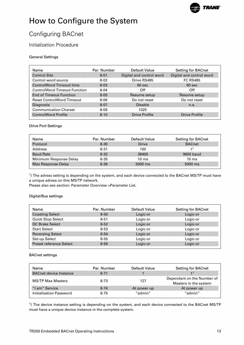
General Settings
Name Par. Number Default Value Setting for BACnet
Control Site 8-01 Digital and control word Digital and control word
Control word source 8-02 Drive RS485 FC RS485
ControlWord Timeout time 8-03 60 sec 60 sec
ControlWord Timeout Function 8-04 Off Off
End of Timeout Function 8-05 Resume setup Resume setup
Reset ControlWord Timeout 8-06 Do not reset Do not reset
Diagnosis 8-07 Disable n.a.
Communication Charset 8-09 1025
ControlWord Profile 8-10 Drive Profile Drive Profile
Drive Port Settings
Name Par. Number Default Value Setting for BACnet
Protocol 8-30 Drive BACnet
Address 8-31 100 11
Baud Rate 8-32 38400 9600 baud
Minimum Response Delay 8-35 10 ms 10 ms
Max Response Delay 8-36 5000 ms 5000 ms
1) The adress setting is depending on the system, and each device connected to the BACnet MS/TP must have
a unique adress on this MS/TP network.
Please also see section: Parameter Overview >Parameter List.
Digital/Bus settings
Name Par. Number Default Value Setting for BACnet
Coasting Select 8-50 Logic-or Logic-or
Quick Stop Select 8-51 Logic-or Logic-or
DC Brake Select 8-52 Logic-or Logic-or
Start Select 8-53 Logic-or Logic-or
Reversing Select 8-54 Logic-or Logic-or
Set-up Select 8-55 Logic-or Logic-or
Preset reference Select 8-56 Logic-or Logic-or
BACnet settings
Name Par. Number Default Value Setting for BACnet
BACnet device Instance 8-71 1 11
MS/TP Max Masters 8-73 127Dependant on the Number of
Masters in the system
“I am” Service 8-74 At power up At power up
Initialisation Password 8-75 “admin” “admin”
1) The device instance setting is depending on the system, and each device connected to the BACnet MS/TP
must have a unique device instance in the complete system.
TR200 Embedded BACnet Operating Instructions 13
Control Word Time-out FunctionPar. 8-03 Control Timeout Time and par. 8-04 Control Timeout Function are not enabled in this version of the
BACnet option.
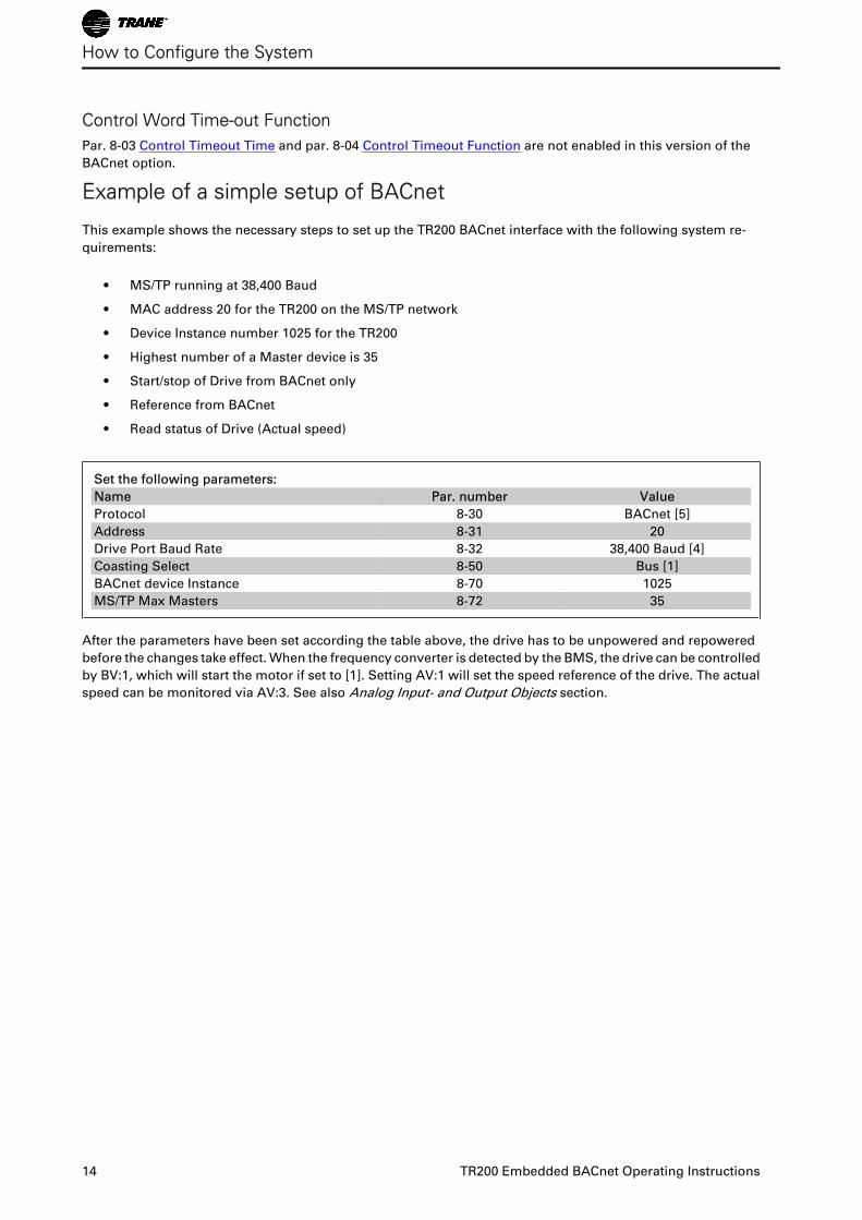
Example of a simple setup of BACnet
This example shows the necessary steps to set up the TR200 BACnet interface with the following system re-
quirements:
• MS/TP running at 38,400 Baud
• MAC address 20 for the TR200 on the MS/TP network
• Device Instance number 1025 for the TR200
• Highest number of a Master device is 35
• Start/stop of Drive from BACnet only
• Reference from BACnet
• Read status of Drive (Actual speed)
Set the following parameters:
Name Par. number Value
Protocol 8-30 BACnet [5]
Address 8-31 20
Drive Port Baud Rate 8-32 38,400 Baud [4]
Coasting Select 8-50 Bus [1]
BACnet device Instance 8-70 1025
MS/TP Max Masters 8-72 35
After the parameters have been set according the table above, the drive has to be unpowered and repowered
before the changes take effect. When the frequency converter is detected by the BMS, the drive can be controlled
by BV:1, which will start the motor if set to [1]. Setting AV:1 will set the speed reference of the drive. The actual
speed can be monitored via AV:3. See also Analog Input- and Output Objects section.
How to Configure the System
14 TR200 Embedded BACnet Operating Instructions
How to Control the Frequency Converter
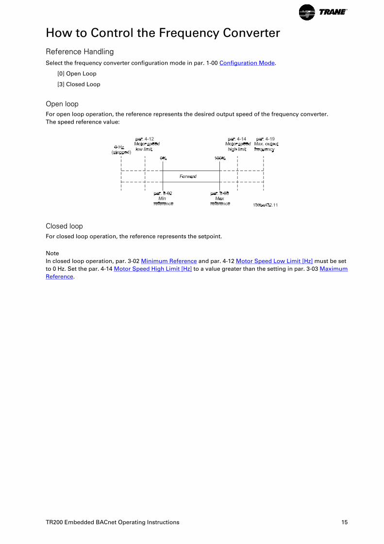
Reference HandlingSelect the frequency converter configuration mode in par. 1-00 Configuration Mode.
[0] Open Loop
[3] Closed Loop
Open loopFor open loop operation, the reference represents the desired output speed of the frequency converter.
The speed reference value:
Closed loopFor closed loop operation, the reference represents the setpoint.
Note
In closed loop operation, par. 3-02 Minimum Reference and par. 4-12 Motor Speed Low Limit [Hz] must be set
to 0 Hz. Set the par. 4-14 Motor Speed High Limit [Hz] to a value greater than the setting in par. 3-03 Maximum
Reference.
TR200 Embedded BACnet Operating Instructions 15
Network Frequency Converter Control Inputs and -Outputs
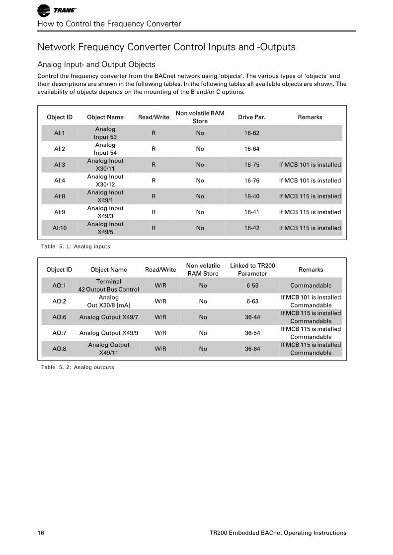
Analog Input- and Output ObjectsControl the frequency converter from the BACnet network using 'objects'. The various types of 'objects' and
their descriptions are shown in the following tables. In the following tables all available objects are shown. The
availability of objects depends on the mounting of the B and/or C options.
Object ID Object Name Read/WriteNon volatile RAM
StoreDrive Par. Remarks
AI:1Analog
Input 53R No 16-62
AI:2Analog
Input 54R No 16-64
AI:3Analog Input
X30/11R No 16-75 If MCB 101 is installed
AI:4Analog Input
X30/12R No 16-76 If MCB 101 is installed
AI:8Analog Input
X49/1R No 18-40 If MCB 115 is installed
AI:9Analog Input
X49/3R No 18-41 If MCB 115 is installed
AI:10Analog Input
X49/5R No 18-42 If MCB 115 is installed
Table 5. 1: Analog inputs
Object ID Object Name Read/WriteNon volatile
RAM Store
Linked to TR200
ParameterRemarks
AO:1Terminal
42 Output Bus ControlW/R No 6-53 Commandable
AO:2Analog
Out X30/8 [mA]W/R No 6-63
If MCB 101 is installed
Commandable
AO:6 Analog Output X49/7 W/R No 36-44If MCB 115 is installed
Commandable
AO:7 Analog Output X49/9 W/R No 36-54If MCB 115 is installed
Commandable
AO:8Analog Output
X49/11W/R No 36-64
If MCB 115 is installed
Commandable
Table 5. 2: Analog outputs
How to Control the Frequency Converter
16 TR200 Embedded BACnet Operating Instructions
Object ID Object Name Read/WriteNon volatile
RAM Store
TR200
ParameterRemarks
AV:11 Input Reference 1 W/R No Commandable
AV:21 Input Reference 2 W/R No Commandable
AV:32 Output Speed Read No
AV:43 PID Feedback Read No
AV:5 Motor Current Read No 16-14
AV:6 Power [kW] Read No 16-10
AV:7 kWh Counter Read No 15-02
AV:8 Inverter Thermal Read No 16-35
AV:11 Motor Voltage Read No 16-12
AV:12 Frequency Read No 16-13
AV:13 Torque [%] Read No 16-22
AV:14 DC Link Voltage Read No 16-30
AV:15 Motor Thermal Read No 16-18
AV:16 Heatsink Temp. Read TR200 16-34
AV:17 Operating Hours Read TR200 15-00
AV:18 Running Hours Read TR200 15-01
AV:19 Bus Feedback 1 W/R TR200 8-94
AV:20 Bus Feedback 2 W/R TR200 8-95
AV:21 Bus Feedback 3 W/R TR200 8-96
AV:22 PID Start Speed [Hz] W/R TR200 20-83
AV:23 On Reference Bandwidth W/R TR200 20-84
AV:24 PID Proportional Gain W/R TR200 20-93
AV:25 PID Integral Time W/R TR200 20-94
AV:26 PID Differentiation Time W/R N/A 20-95
AV:27 PID Diff. Gain Limit W/R TR200 20-96
AV:28 Slave Messages Rcvd Read TR200 8-82
AV:29 Slave Error Count Read TR200 8-83
AV:30 Slave Messages Sent Read N/A 8-84
AV:50 Alarm Log: Error Code Read TR200 15-30
AV:514 Fault Code Read TR200
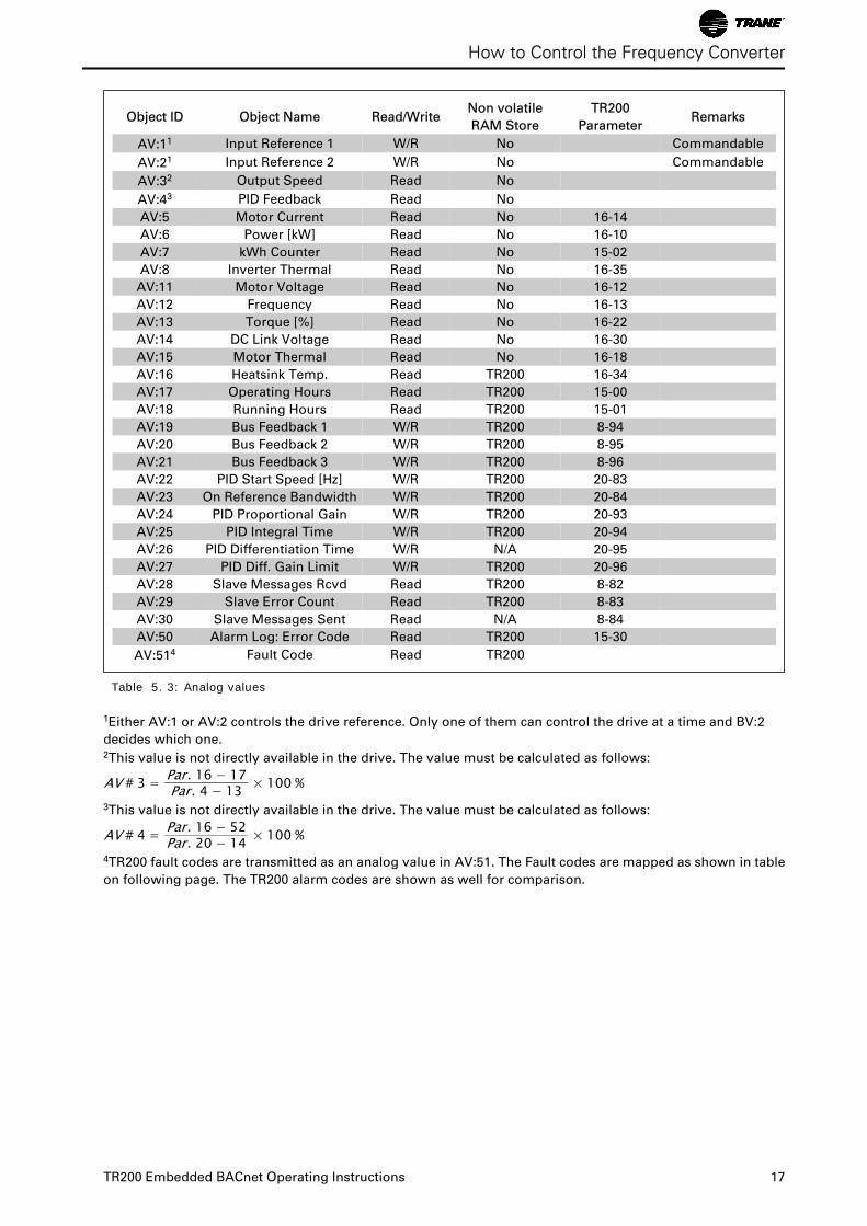
Table 5. 3: Analog values
1Either AV:1 or AV:2 controls the drive reference. Only one of them can control the drive at a time and BV:2
decides which one.2This value is not directly available in the drive. The value must be calculated as follows:
AV # 3 = Par. 16 − 17Par. 4 − 13 × 100 %
3This value is not directly available in the drive. The value must be calculated as follows:
AV # 4 = Par. 16 − 52Par. 20 − 14 × 100 %
4TR200 fault codes are transmitted as an analog value in AV:51. The Fault codes are mapped as shown in table
on following page. The TR200 alarm codes are shown as well for comparison.
How to Control the Frequency Converter
TR200 Embedded BACnet Operating Instructions 17
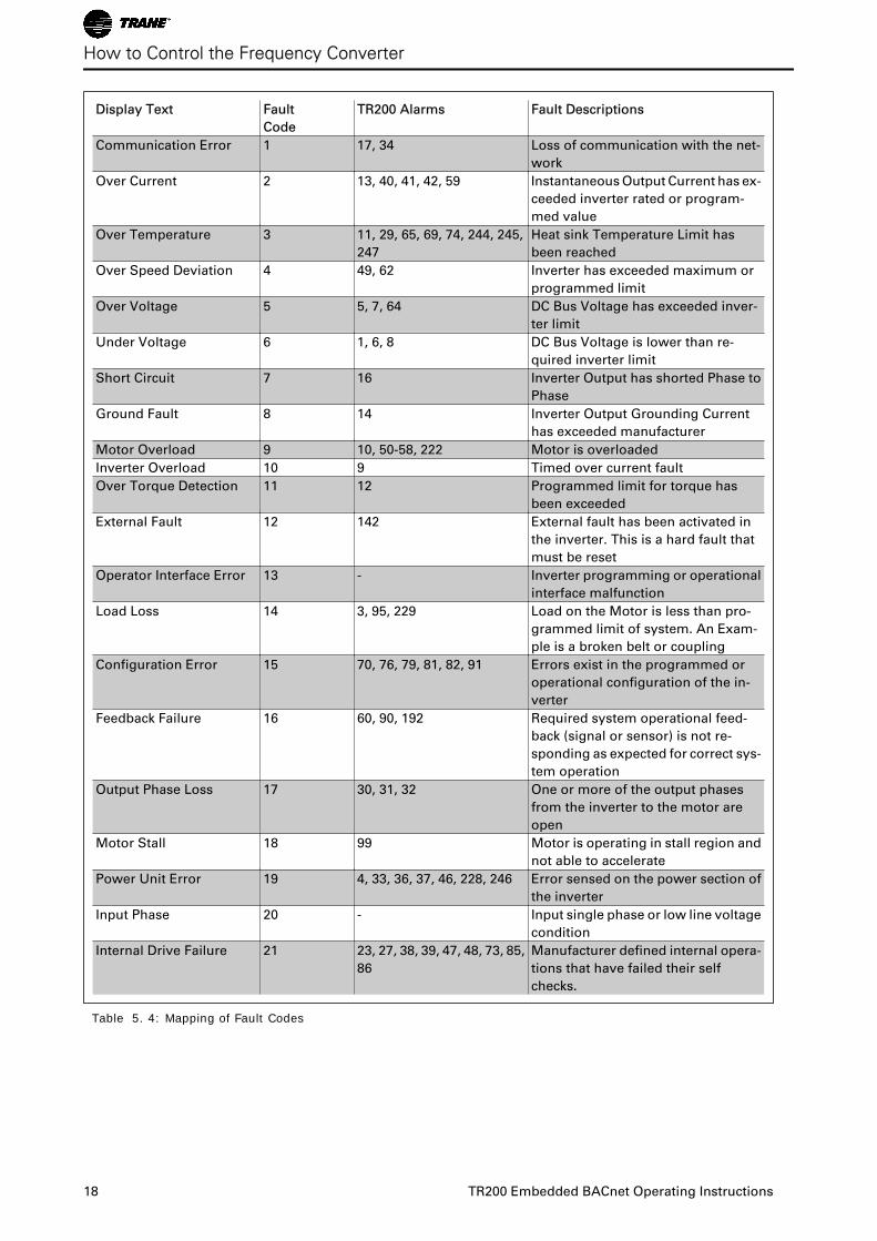
Display Text Fault
Code
TR200 Alarms Fault Descriptions
Communication Error 1 17, 34 Loss of communication with the net-
work
Over Current 2 13, 40, 41, 42, 59 Instantaneous Output Current has ex-
ceeded inverter rated or program-
med value
Over Temperature 3 11, 29, 65, 69, 74, 244, 245,
247
Heat sink Temperature Limit has
been reached
Over Speed Deviation 4 49, 62 Inverter has exceeded maximum or
programmed limit
Over Voltage 5 5, 7, 64 DC Bus Voltage has exceeded inver-
ter limit
Under Voltage 6 1, 6, 8 DC Bus Voltage is lower than re-
quired inverter limit
Short Circuit 7 16 Inverter Output has shorted Phase to
Phase
Ground Fault 8 14 Inverter Output Grounding Current
has exceeded manufacturer
Motor Overload 9 10, 50-58, 222 Motor is overloaded
Inverter Overload 10 9 Timed over current fault
Over Torque Detection 11 12 Programmed limit for torque has
been exceeded
External Fault 12 142 External fault has been activated in
the inverter. This is a hard fault that
must be reset
Operator Interface Error 13 - Inverter programming or operational
interface malfunction
Load Loss 14 3, 95, 229 Load on the Motor is less than pro-
grammed limit of system. An Exam-
ple is a broken belt or coupling
Configuration Error 15 70, 76, 79, 81, 82, 91 Errors exist in the programmed or
operational configuration of the in-
verter
Feedback Failure 16 60, 90, 192 Required system operational feed-
back (signal or sensor) is not re-
sponding as expected for correct sys-
tem operation
Output Phase Loss 17 30, 31, 32 One or more of the output phases
from the inverter to the motor are
open
Motor Stall 18 99 Motor is operating in stall region and
not able to accelerate
Power Unit Error 19 4, 33, 36, 37, 46, 228, 246 Error sensed on the power section of
the inverter
Input Phase 20 - Input single phase or low line voltage
condition
Internal Drive Failure 21 23, 27, 38, 39, 47, 48, 73, 85,
86
Manufacturer defined internal opera-
tions that have failed their self
checks.
Table 5. 4: Mapping of Fault Codes
How to Control the Frequency Converter
18 TR200 Embedded BACnet Operating Instructions
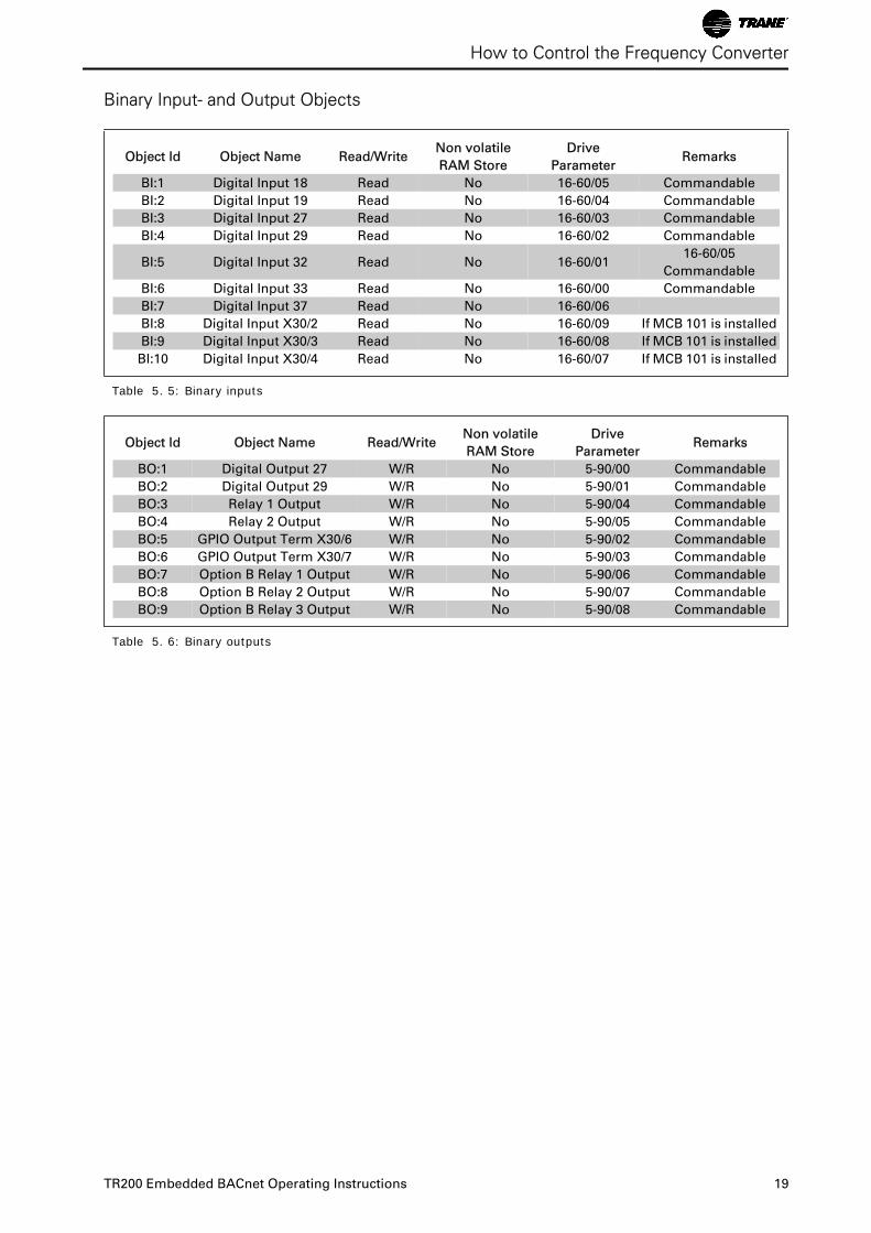
Binary Input- and Output Objects
Object Id Object Name Read/WriteNon volatile
RAM Store
Drive
ParameterRemarks
BI:1 Digital Input 18 Read No 16-60/05 Commandable
BI:2 Digital Input 19 Read No 16-60/04 Commandable
BI:3 Digital Input 27 Read No 16-60/03 Commandable
BI:4 Digital Input 29 Read No 16-60/02 Commandable
BI:5 Digital Input 32 Read No 16-60/0116-60/05
Commandable
BI:6 Digital Input 33 Read No 16-60/00 Commandable
BI:7 Digital Input 37 Read No 16-60/06
BI:8 Digital Input X30/2 Read No 16-60/09 If MCB 101 is installed
BI:9 Digital Input X30/3 Read No 16-60/08 If MCB 101 is installed
BI:10 Digital Input X30/4 Read No 16-60/07 If MCB 101 is installed
Table 5. 5: Binary inputs
Object Id Object Name Read/WriteNon volatile
RAM Store
Drive
ParameterRemarks
BO:1 Digital Output 27 W/R No 5-90/00 Commandable
BO:2 Digital Output 29 W/R No 5-90/01 Commandable
BO:3 Relay 1 Output W/R No 5-90/04 Commandable
BO:4 Relay 2 Output W/R No 5-90/05 Commandable
BO:5 GPIO Output Term X30/6 W/R No 5-90/02 Commandable
BO:6 GPIO Output Term X30/7 W/R No 5-90/03 Commandable
BO:7 Option B Relay 1 Output W/R No 5-90/06 Commandable
BO:8 Option B Relay 2 Output W/R No 5-90/07 Commandable
BO:9 Option B Relay 3 Output W/R No 5-90/08 Commandable
Table 5. 6: Binary outputs
How to Control the Frequency Converter
TR200 Embedded BACnet Operating Instructions 19
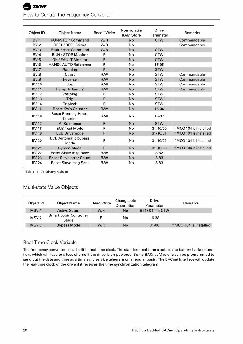
Object ID Object Name Read / WriteNon volatile
RAM Store
Drive
ParameterRemarks
BV:1 RUN/STOP Command W/R No CTW Commandable
BV:2 REF1 / REF2 Select W/R No Commandable
BV:3 Fault Reset Command W/R No CTW
BV:4 RUN / STOP Monitor R No CTW
BV:5 OK / FAULT Monitor R No CTW
BV:6 HAND / AUTO Reference R No 16-95
BV:7 Running R No STW
BV:8 Coast R/W No STW Commandable
BV:9 Reverse R/W No STW Commandable
BV:10 Jog R/W No STW Commandable
BV:11 Ramp 1/Ramp 2 R/W No STW Commandable
BV:12 Warning R No STW
BV:13 Trip R No STW
BV:14 Triplock R No STW
BV:15 Reset KWh Counter R/W No 15-06
BV:16Reset Running Hours
CounterR/W No 15-07
BV:17 At Reference R No STW
BV:18 ECB Test Mode R No 31-10/00 If MCO 104 is installed
BV:19 ECB Drivemode R No 31-10/01 If MCO 104 is installed
BV:20ECB Automatic bypass
modeR No 31-10/02 If MCO 104 is installed
BV:21 Bypass Mode R No 31-10/03 If MCO 104 is installed
BV:22 Reset Slave msg Recv R/W No 8-82
BV:23 Reset Slave error Count R/W No 8-83
BV:24 Reset Slave msg Sent R/W No 8-83
Table 5. 7: Binary values
Multi-state Value Objects
Object Id Object Name Read/WriteChangeable
Description
Drive
ParameterRemarks
MSV:1 Active Setup W/R No Bit13&14 in CTW
MSV:2Smart Logic Controller
StageR No 16-38
MSV:3 Bypass Mode W/R No 31-00 If MCO 104 is installed
Real Time Clock VariableThe frequency converter has a built-in real-time clock. The standard real-time clock has no battery backup func-
tion, which will lead to a loss of time if the drive is un-powered. Some BACnet Master's can be programmed to
send out the date and time as a time sync service telegram on a regular basis. The BACnet Interface will update
the real-time clock of the drive if it receives the time synchronization telegram.
How to Control the Frequency Converter
20 TR200 Embedded BACnet Operating Instructions
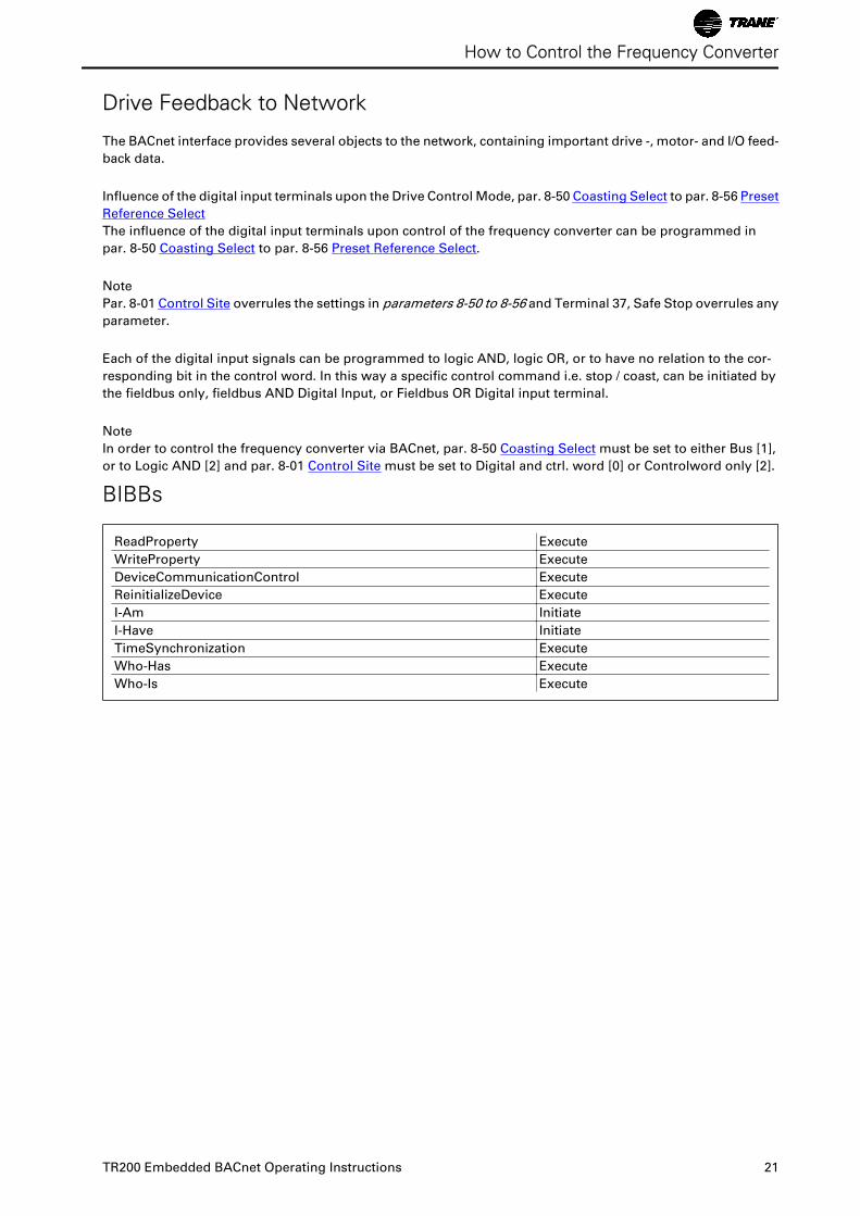
Drive Feedback to Network
The BACnet interface provides several objects to the network, containing important drive -, motor- and I/O feed-
back data.
Influence of the digital input terminals upon the Drive Control Mode, par. 8-50 Coasting Select to par. 8-56 Preset
Reference Select
The influence of the digital input terminals upon control of the frequency converter can be programmed in
par. 8-50 Coasting Select to par. 8-56 Preset Reference Select.
Note
Par. 8-01 Control Site overrules the settings in parameters 8-50 to 8-56 and Terminal 37, Safe Stop overrules any
parameter.
Each of the digital input signals can be programmed to logic AND, logic OR, or to have no relation to the cor-
responding bit in the control word. In this way a specific control command i.e. stop / coast, can be initiated by
the fieldbus only, fieldbus AND Digital Input, or Fieldbus OR Digital input terminal.
Note
In order to control the frequency converter via BACnet, par. 8-50 Coasting Select must be set to either Bus [1],
or to Logic AND [2] and par. 8-01 Control Site must be set to Digital and ctrl. word [0] or Controlword only [2].
BIBBs
ReadProperty Execute
WriteProperty Execute
DeviceCommunicationControl Execute
ReinitializeDevice Execute
I-Am Initiate
I-Have Initiate
TimeSynchronization Execute
Who-Has Execute
Who-Is Execute
How to Control the Frequency Converter
TR200 Embedded BACnet Operating Instructions 21
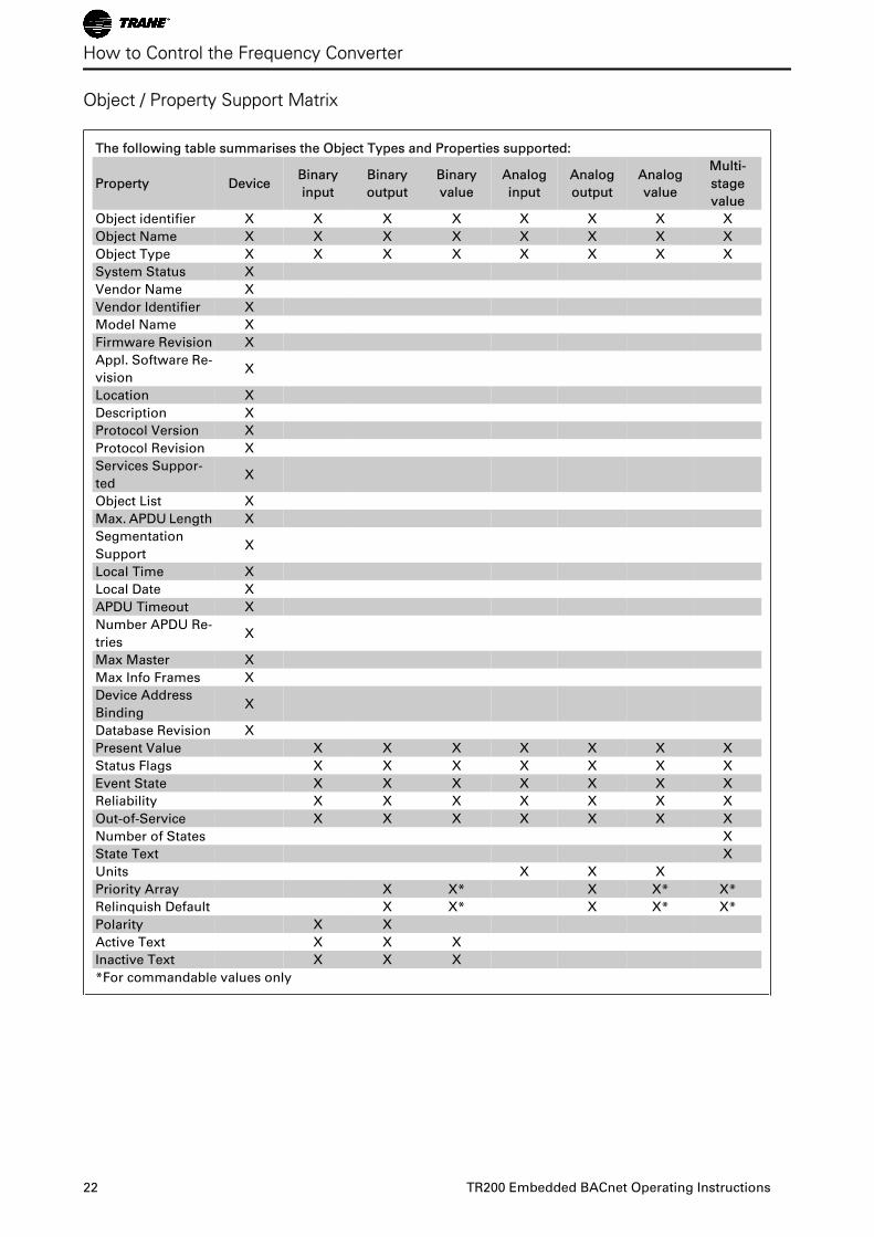
Object / Property Support Matrix
The following table summarises the Object Types and Properties supported:
Property DeviceBinary
input
Binary
output
Binary
value
Analog
input
Analog
output
Analog
value
Multi-
stage
value
Object identifier X X X X X X X X
Object Name X X X X X X X X
Object Type X X X X X X X X
System Status X
Vendor Name X
Vendor Identifier X
Model Name X
Firmware Revision X
Appl. Software Re-
visionX
Location X
Description X
Protocol Version X
Protocol Revision X
Services Suppor-
tedX
Object List X
Max. APDU Length X
Segmentation
SupportX
Local Time X
Local Date X
APDU Timeout X
Number APDU Re-
triesX
Max Master X
Max Info Frames X
Device Address
BindingX
Database Revision X
Present Value X X X X X X X
Status Flags X X X X X X X
Event State X X X X X X X
Reliability X X X X X X X
Out-of-Service X X X X X X X
Number of States X
State Text X
Units X X X
Priority Array X X* X X* X*
Relinquish Default X X* X X* X*
Polarity X X
Active Text X X X
Inactive Text X X X
*For commandable values only
How to Control the Frequency Converter
22 TR200 Embedded BACnet Operating Instructions
Parameters
Parameter Overview
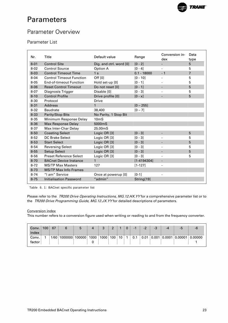
Parameter List
Nr. Title Default value RangeConversion in-
dex
Data
type
8-01 Control Site Dig. and ctrl. word [0] [0 - 2] - 5
8-02 Control Source Option A [0 - 4] - 5
8-03 Control Timeout Time 1 s 0.1 - 18000 - 1 7
8-04 Control Timeout Function Off [0] [0 - 10] - 5
8-05 End-of-timeout Function Hold set-up [0] [0 - 1] - 5
8-06 Reset Control Timeout Do not reset [0] [0 - 1] - 5
8-07 Diagnosis Trigger Disable [0] [0 - 3] - 5
8-10 Control Profile Drive profile [0] [0 - x] - 5
8-30 Protocol Drive
8-31 Address 1 [0 – 255]
8-32 Baudrate 38,400 [0 – 7]
8-33 Parity/Stop Bits No Parity, 1 Stop Bit
8-35 Minimum Response Delay 10mS
8-36 Max Response Delay 5000mS
8-37 Max Inter-Char Delay 25.00mS
8-50 Coasting Select Logic OR [3] [0 - 3] - 5
8-52 DC Brake Select Logic OR [3] [0 - 3] - 5
8-53 Start Select Logic OR [3] [0 - 3] - 5
8-54 Reversing Select Logic OR [3] [0 - 3] - 5
8-55 Setup Select Logic OR [3] [0 - 3] - 5
8-56 Preset Reference Select Logic OR [3] [0 - 3] - 5
8-70 BACnet Device Instance 1 [1-4194304] -
8-72 MS/TP Max Masters 127 [1-127] -
8-73 MS/TP Max Info Frames
8-74 “I am” Service Once at powerup [0] [0-1] -
8-75 Initialisation Password “admin” String[19]
Table 6. 1: BACnet specific parameter list
Please refer to the TR200 Drive Operating Instructions, MG.12.HX.YY for a comprehensive parameter list or to
the TR200 Drive Programming Guide, MG.12.JX.YY for detailed descriptions of parameters.
Conversion index
This number refers to a conversion figure used when writing or reading to and from the frequency converter.
Conv.
index
100 67 6 5 4 3 2 1 0 -1 -2 -3 -4 -5 -6
Conv.
factor
1 1/60 1000000 100000 1000
0
1000 100 10 1 0.1 0.01 0.001 0.0001 0.00001 0.00000
1
TR200 Embedded BACnet Operating Instructions 23
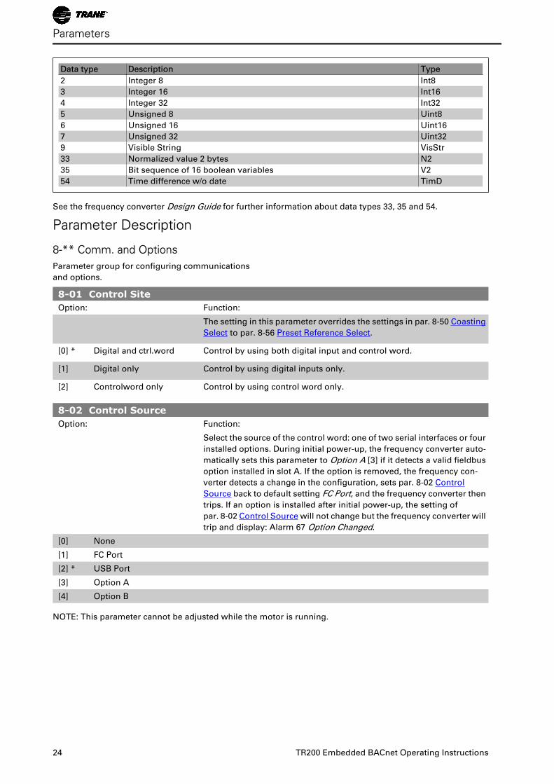
Data type Description Type
2 Integer 8 Int8
3 Integer 16 Int16
4 Integer 32 Int32
5 Unsigned 8 Uint8
6 Unsigned 16 Uint16
7 Unsigned 32 Uint32
9 Visible String VisStr
33 Normalized value 2 bytes N2
35 Bit sequence of 16 boolean variables V2
54 Time difference w/o date TimD
See the frequency converter Design Guide for further information about data types 33, 35 and 54.
Parameter Description
8-** Comm. and Options Parameter group for configuring communications
and options.
8-01 Control SiteOption: Function:
The setting in this parameter overrides the settings in par. 8-50 Coasting
Select to par. 8-56 Preset Reference Select.
[0] * Digital and ctrl.word Control by using both digital input and control word.
[1] Digital only Control by using digital inputs only.
[2] Controlword only Control by using control word only.
8-02 Control SourceOption: Function:
Select the source of the control word: one of two serial interfaces or four
installed options. During initial power-up, the frequency converter auto-
matically sets this parameter to Option A [3] if it detects a valid fieldbus
option installed in slot A. If the option is removed, the frequency con-
verter detects a change in the configuration, sets par. 8-02 Control
Source back to default setting FC Port, and the frequency converter then
trips. If an option is installed after initial power-up, the setting of
par. 8-02 Control Source will not change but the frequency converter will
trip and display: Alarm 67 Option Changed.
[0] None
[1] FC Port
[2] * USB Port
[3] Option A
[4] Option B
NOTE: This parameter cannot be adjusted while the motor is running.
Parameters
24 TR200 Embedded BACnet Operating Instructions
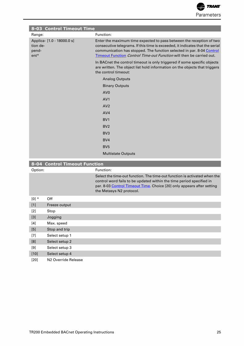
8-03 Control Timeout TimeRange: Function:
Applica-
tion de-
pend-
ent*
[1.0 - 18000.0 s] Enter the maximum time expected to pass between the reception of two
consecutive telegrams. If this time is exceeded, it indicates that the serial
communication has stopped. The function selected in par. 8-04 Control
Timeout Function Control Time-out Function will then be carried out.
In BACnet the control timeout is only triggered if some specific objects
are written. The object list hold information on the objects that triggers
the control timeout:
Analog Outputs
Binary Outputs
AV0
AV1
AV2
AV4
BV1
BV2
BV3
BV4
BV5
Multistate Outputs
8-04 Control Timeout FunctionOption: Function:
Select the time-out function. The time-out function is activated when the
control word fails to be updated within the time period specified in
par. 8-03 Control Timeout Time. Choice [20] only appears after setting
the Metasys N2 protocol.
[0] * Off
[1] Freeze output
[2] Stop
[3] Jogging
[4] Max. speed
[5] Stop and trip
[7] Select setup 1
[8] Select setup 2
[9] Select setup 3
[10] Select setup 4
[20] N2 Override Release
Parameters
TR200 Embedded BACnet Operating Instructions 25
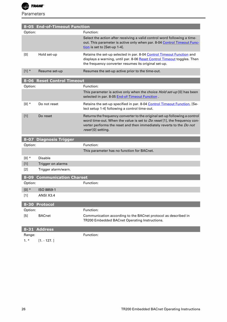
8-05 End-of-Timeout FunctionOption: Function:
Select the action after receiving a valid control word following a time-
out. This parameter is active only when par. 8-04 Control Timeout Func-
tion is set to [Set-up 1-4].
[0] Hold set-up Retains the set-up selected in par. 8-04 Control Timeout Function and
displays a warning, until par. 8-06 Reset Control Timeout toggles. Then
the frequency converter resumes its original set-up.
[1] * Resume set-up Resumes the set-up active prior to the time-out.
8-06 Reset Control TimeoutOption: Function:
This parameter is active only when the choice Hold set-up [0] has been
selected in par. 8-05 End-of-Timeout Function .
[0] * Do not reset Retains the set-up specified in par. 8-04 Control Timeout Function, [Se-
lect setup 1-4] following a control time-out.
[1] Do reset Returns the frequency converter to the original set-up following a control
word time-out. When the value is set to Do reset [1], the frequency con-
verter performs the reset and then immediately reverts to the Do not
reset [0] setting.
8-07 Diagnosis TriggerOption: Function:
This parameter has no function for BACnet.
[0] * Disable
[1] Trigger on alarms
[2] Trigger alarm/warn.
8-09 Communication CharsetOption: Function:
[0] * ISO 8859-1
[1] ANSI X3.4
8-30 ProtocolOption: Function:
[5] BACnet Communication according to the BACnet protocol as described in
TR200 Embedded BACnet Operating Instructions.
8-31 AddressRange: Function:
1. * [1. - 127. ]
Parameters
26 TR200 Embedded BACnet Operating Instructions
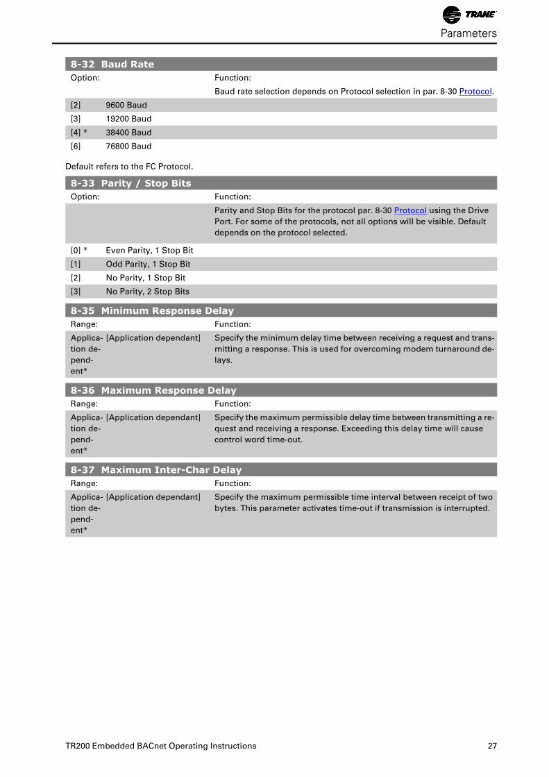
8-32 Baud RateOption: Function:
Baud rate selection depends on Protocol selection in par. 8-30 Protocol.
[2] 9600 Baud
[3] 19200 Baud
[4] * 38400 Baud
[6] 76800 Baud
Default refers to the FC Protocol.
8-33 Parity / Stop BitsOption: Function:
Parity and Stop Bits for the protocol par. 8-30 Protocol using the Drive
Port. For some of the protocols, not all options will be visible. Default
depends on the protocol selected.
[0] * Even Parity, 1 Stop Bit
[1] Odd Parity, 1 Stop Bit
[2] No Parity, 1 Stop Bit
[3] No Parity, 2 Stop Bits
8-35 Minimum Response DelayRange: Function:
Applica-
tion de-
pend-
ent*
[Application dependant] Specify the minimum delay time between receiving a request and trans-
mitting a response. This is used for overcoming modem turnaround de-
lays.
8-36 Maximum Response DelayRange: Function:
Applica-
tion de-
pend-
ent*
[Application dependant] Specify the maximum permissible delay time between transmitting a re-
quest and receiving a response. Exceeding this delay time will cause
control word time-out.
8-37 Maximum Inter-Char DelayRange: Function:
Applica-
tion de-
pend-
ent*
[Application dependant] Specify the maximum permissible time interval between receipt of two
bytes. This parameter activates time-out if transmission is interrupted.
Parameters
TR200 Embedded BACnet Operating Instructions 27
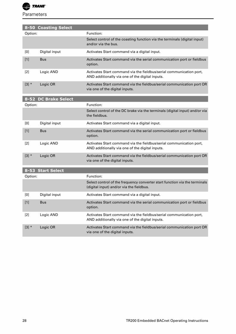
8-50 Coasting SelectOption: Function:
Select control of the coasting function via the terminals (digital input)
and/or via the bus.
[0] Digital input Activates Start command via a digital input.
[1] Bus Activates Start command via the serial communication port or fieldbus
option.
[2] Logic AND Activates Start command via the fieldbus/serial communication port,
AND additionally via one of the digital inputs.
[3] * Logic OR Activates Start command via the fieldbus/serial communication port OR
via one of the digital inputs.
8-52 DC Brake SelectOption: Function:
Select control of the DC brake via the terminals (digital input) and/or via
the fieldbus.
[0] Digital input Activates Start command via a digital input.
[1] Bus Activates Start command via the serial communication port or fieldbus
option.
[2] Logic AND Activates Start command via the fieldbus/serial communication port,
AND additionally via one of the digital inputs.
[3] * Logic OR Activates Start command via the fieldbus/serial communication port OR
via one of the digital inputs.
8-53 Start SelectOption: Function:
Select control of the frequency converter start function via the terminals
(digital input) and/or via the fieldbus.
[0] Digital input Activates Start command via a digital input.
[1] Bus Activates Start command via the serial communication port or fieldbus
option.
[2] Logic AND Activates Start command via the fieldbus/serial communication port,
AND additionally via one of the digital inputs.
[3] * Logic OR Activates Start command via the fieldbus/serial communication port OR
via one of the digital inputs.
Parameters
28 TR200 Embedded BACnet Operating Instructions
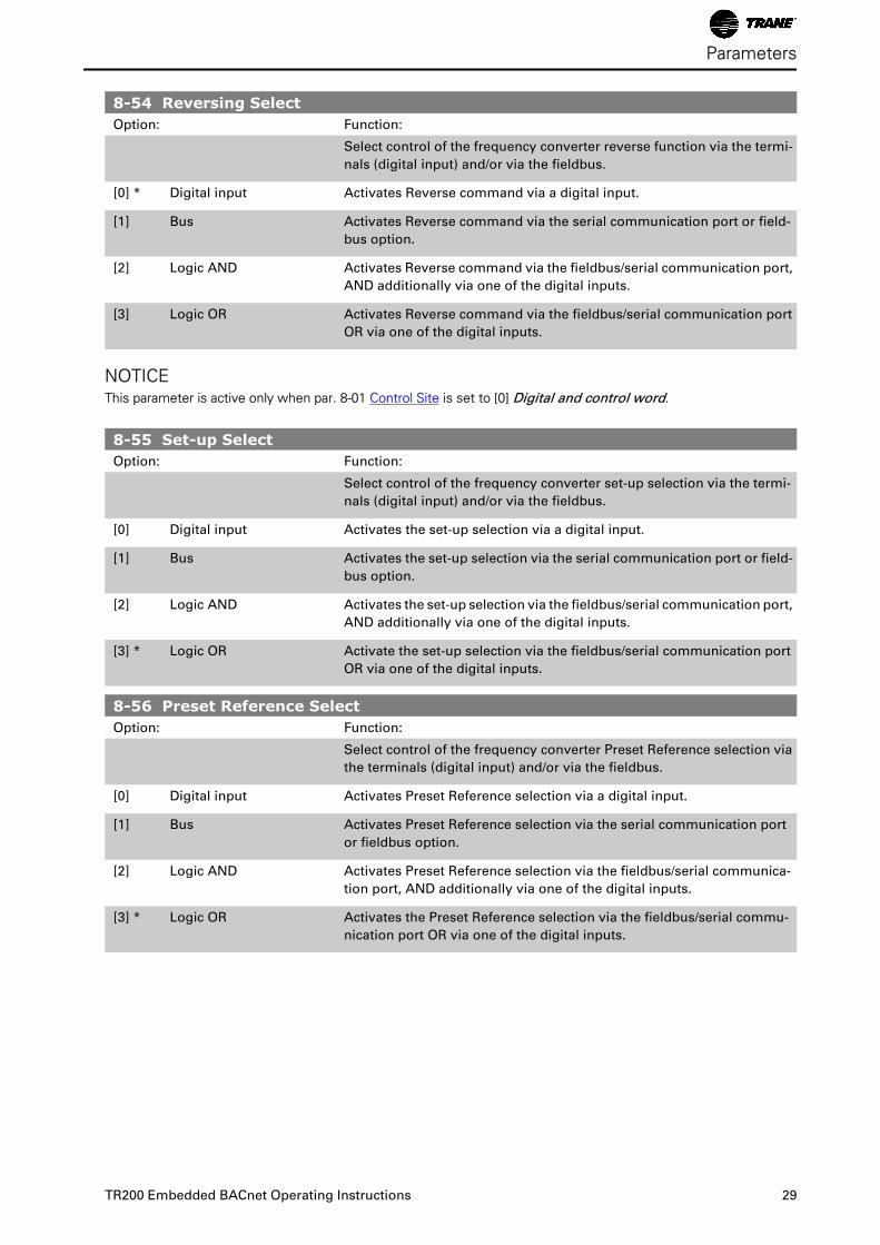
8-54 Reversing SelectOption: Function:
Select control of the frequency converter reverse function via the termi-
nals (digital input) and/or via the fieldbus.
[0] * Digital input Activates Reverse command via a digital input.
[1] Bus Activates Reverse command via the serial communication port or field-
bus option.
[2] Logic AND Activates Reverse command via the fieldbus/serial communication port,
AND additionally via one of the digital inputs.
[3] Logic OR Activates Reverse command via the fieldbus/serial communication port
OR via one of the digital inputs.
NOTICEThis parameter is active only when par. 8-01 Control Site is set to [0] Digital and control word.
8-55 Set-up SelectOption: Function:
Select control of the frequency converter set-up selection via the termi-
nals (digital input) and/or via the fieldbus.
[0] Digital input Activates the set-up selection via a digital input.
[1] Bus Activates the set-up selection via the serial communication port or field-
bus option.
[2] Logic AND Activates the set-up selection via the fieldbus/serial communication port,
AND additionally via one of the digital inputs.
[3] * Logic OR Activate the set-up selection via the fieldbus/serial communication port
OR via one of the digital inputs.
8-56 Preset Reference SelectOption: Function:
Select control of the frequency converter Preset Reference selection via
the terminals (digital input) and/or via the fieldbus.
[0] Digital input Activates Preset Reference selection via a digital input.
[1] Bus Activates Preset Reference selection via the serial communication port
or fieldbus option.
[2] Logic AND Activates Preset Reference selection via the fieldbus/serial communica-
tion port, AND additionally via one of the digital inputs.
[3] * Logic OR Activates the Preset Reference selection via the fieldbus/serial commu-
nication port OR via one of the digital inputs.
Parameters
TR200 Embedded BACnet Operating Instructions 29
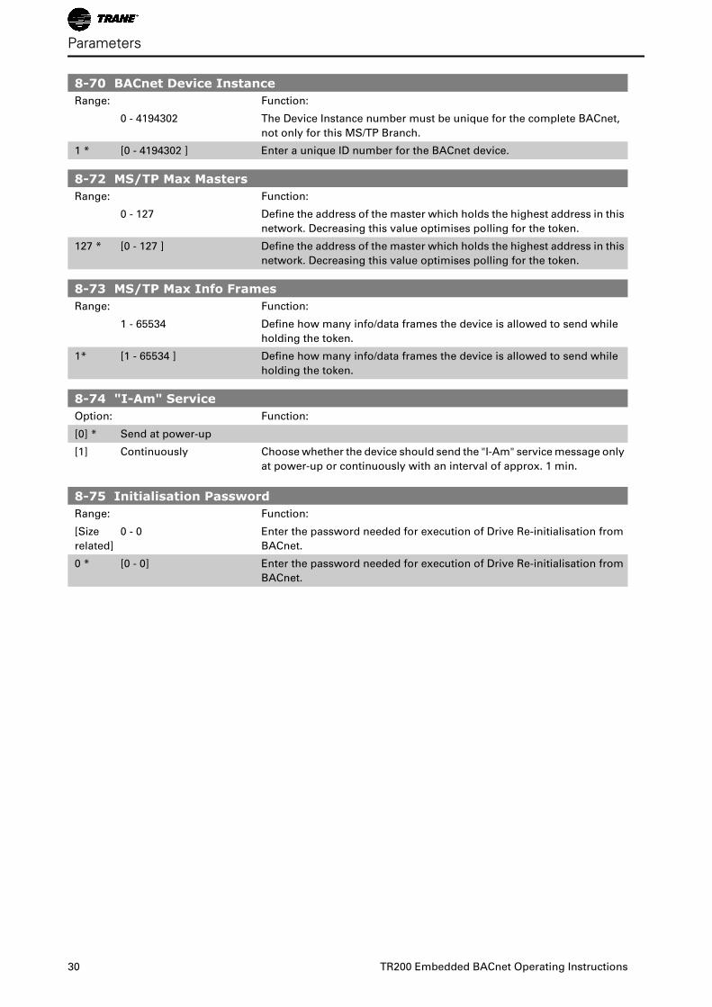
8-70 BACnet Device InstanceRange: Function:
0 - 4194302 The Device Instance number must be unique for the complete BACnet,
not only for this MS/TP Branch.
1 * [0 - 4194302 ] Enter a unique ID number for the BACnet device.
8-72 MS/TP Max MastersRange: Function:
0 - 127 Define the address of the master which holds the highest address in this
network. Decreasing this value optimises polling for the token.
127 * [0 - 127 ] Define the address of the master which holds the highest address in this
network. Decreasing this value optimises polling for the token.
8-73 MS/TP Max Info FramesRange: Function:
1 - 65534 Define how many info/data frames the device is allowed to send while
holding the token.
1* [1 - 65534 ] Define how many info/data frames the device is allowed to send while
holding the token.
8-74 "I-Am" ServiceOption: Function:
[0] * Send at power-up
[1] Continuously Choose whether the device should send the "I-Am" service message only
at power-up or continuously with an interval of approx. 1 min.
8-75 Initialisation PasswordRange: Function:
[Size
related]
0 - 0 Enter the password needed for execution of Drive Re-initialisation from
BACnet.
0 * [0 - 0] Enter the password needed for execution of Drive Re-initialisation from
BACnet.
Parameters
30 TR200 Embedded BACnet Operating Instructions
Troubleshooting
Alarm, Warning and Extended Status Word
Alarm and Warning Messages
GeneralThere is a clear distinction between alarms and warnings. In the event of an alarm, the frequency converter will
enter a fault condition. After the cause for the alarm has been cleared, the master must acknowledge the alarm
message in order to start operation of the frequency converter again. A warning, on the other hand, may appear
when a warning condition arises, then disappear when conditions return to normal without interfering with the
process.
Alarm Word and Warning Word are shown on the display in Hex format. If there is more than one warning or
alarm, a sum of all warnings or alarms will be shown. Warning Word and Alarm Word are displayed in par.
16-90 to 16-95. For more information on the individual alarms and warnings, please refer to: TR200 Design
Guide.
WarningsAll warnings within the frequency converter are represented by a single bit within a Warning Word. A Warning
Word is always an action parameter. Bit status FALSE [0] means no warning, while bit status TRUE [1] means
warning. Each bit status has a corresponding text string message. In addition to the Warning Word message
the master will also be notified via a change to bit 7 in the status word.
AlarmsFollowing an alarm message the frequency converter will enter a fault condition. Only after the fault has been
rectified and the master has acknowledged the alarm message by setting bit 3 in the Control Word, can the FC
resume operation. All alarms within the TR200 are represented by a single bit within an Alarm Word. An Alarm
Word is always an action parameter. Bit status FALSE [0] means no alarm, while bit status TRUE [1] means
alarm.
TR200 Embedded BACnet Operating Instructions 31
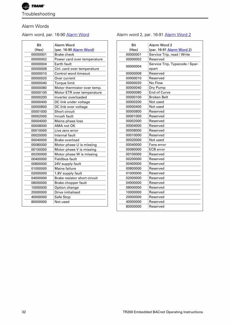
Alarm Words
Alarm word, par. 16-90 Alarm Word
Bit
(Hex)
Alarm Word
(par. 16-90 Alarm Word)
00000001 Brake check
00000002 Power card over temperature
00000004 Earth fault
00000008 Ctrl. card over temperature
00000010 Control word timeout
00000020 Over current
00000040 Torque limit
00000080 Motor thermistor over temp.
00000100 Motor ETR over temperature
00000200 Inverter overloaded
00000400 DC link under voltage
00000800 DC link over voltage
00001000 Short circuit
00002000 Inrush fault
00004000 Mains phase loss
00008000 AMA not OK
00010000 Live zero error
00020000 Internal fault
00040000 Brake overload
00080000 Motor phase U is missing
00100000 Motor phase V is missing
00200000 Motor phase W is missing
00400000 Fieldbus fault
00800000 24V supply fault
01000000 Mains failure
02000000 1.8V supply fault
04000000 Brake resistor short circuit
08000000 Brake chopper fault
10000000 Option change
20000000 Drive initialised
40000000 Safe Stop
80000000 Not used
Alarm word 2, par. 16-91 Alarm Word 2
Bit
(Hex)
Alarm Word 2
(par. 16-91 Alarm Word 2)
00000001 Service Trip, read / Write
00000002 Reserved
00000004Service Trip, Typecode / Spar-
epart
00000008 Reserved
00000010 Reserved
00000020 No Flow
00000040 Dry Pump
00000080 End of Curve
00000100 Broken Belt
00000200 Not used
00000400 Not used
00000800 Reserved
00001000 Reserved
00002000 Reserved
00004000 Reserved
00008000 Reserved
00010000 Reserved
00020000 Not used
00040000 Fans error
00080000 ECB error
00100000 Reserved
00200000 Reserved
00400000 Reserved
00800000 Reserved
01000000 Reserved
02000000 Reserved
04000000 Reserved
08000000 Reserved
10000000 Reserved
20000000 Reserved
40000000 Reserved
80000000 Reserved
Troubleshooting
32 TR200 Embedded BACnet Operating Instructions
Warning Words
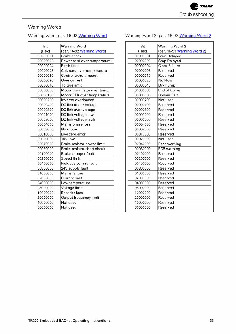
Warning word, par. 16-92 Warning Word
Bit
(Hex)
Warning Word
(par. 16-92 Warning Word)
00000001 Brake check
00000002 Power card over temperature
00000004 Earth fault
00000008 Ctrl. card over temperature
00000010 Control word timeout
00000020 Over current
00000040 Torque limit
00000080 Motor thermistor over temp.
00000100 Motor ETR over temperature
00000200 Inverter overloaded
00000400 DC link under voltage
00000800 DC link over voltage
00001000 DC link voltage low
00002000 DC link voltage high
00004000 Mains phase loss
00008000 No motor
00010000 Live zero error
00020000 10V low
00040000 Brake resistor power limit
00080000 Brake resistor short circuit
00100000 Brake chopper fault
00200000 Speed limit
00400000 Fieldbus comm. fault
00800000 24V supply fault
01000000 Mains failure
02000000 Current limit
04000000 Low temperature
08000000 Voltage limit
10000000 Encoder loss
20000000 Output frequency limit
40000000 Not used
80000000 Not used
Warning word 2, par. 16-93 Warning Word 2
Bit
(Hex)
Warning Word 2
(par. 16-93 Warning Word 2)
00000001 Start Delayed
00000002 Stop Delayed
00000004 Clock Failure
00000008 Reserved
00000010 Reserved
00000020 No Flow
00000040 Dry Pump
00000080 End of Curve
00000100 Broken Belt
00000200 Not used
00000400 Reserved
00000800 Reserved
00001000 Reserved
00002000 Reserved
00004000 Reserved
00008000 Reserved
00010000 Reserved
00020000 Not used
00040000 Fans warning
00080000 ECB warning
00100000 Reserved
00200000 Reserved
00400000 Reserved
00800000 Reserved
01000000 Reserved
02000000 Reserved
04000000 Reserved
08000000 Reserved
10000000 Reserved
20000000 Reserved
40000000 Reserved
80000000 Reserved
Troubleshooting
TR200 Embedded BACnet Operating Instructions 33
Index""i-am" Service 8-74 30
AAbbreviations 7
Alarm And Warning Messages 31
Alarm Word 32
American National Standard 6
Analog Input- And Output Objects 16
Assumptions 6
BBackground Knowledge 7
Bacnet (building Automation And Control Network) 6
Bacnet Cable 11
Bacnet Settings 13
Bacnet Specific Parameter List 23
Bibb's 21
Binary Input- And Output Objects 19
CCable Lengths And Number Of Nodes 8
Cable Routing 11
Cabling 8
Coasting Select 8-50 28
Communication Cable 11
Control Site 8-01 24
Control Timeout Function 8-04 25
Control Timeout Time 8-03 25
Control Word Time-out Function 14
Copyright, Limitation Of Liability And Revision Rights 2
DDc Brake Select 8-52 28
Diagnosis Trigger 8-07 26
Digital/bus Settings 13
Drive Feedback To Network 21
Drive Port Settings 13
EElectrical Ratings 5
Emc Precautions 12
End-of-timeout Function 8-05 26
GGeneral Settings 13
IInitialization Procedure 13
LLiterature 7
MMaximum Inter-char Delay 8-37 27
Maximum Response Delay 8-36 27
Minimum Response Delay 8-35 27
Multiple Ground Shielding 12
Multi-state Value Objects 20
Index
34 TR200 Embedded BACnet Operating Instructions
NNetwork Connection 8
Network Frequency Converter Control Inputs And -outputs 16
Network Termination 9
OObject / Property Support Matrix 22
PParameter List 23
Parity / Stop Bits 8-33 27
Preset Reference Select 8-56 29
RReal Time Clock Variable 20
Reference Handling 15
Reset Control Timeout 8-06 26
Reversing Select 8-54 29
SSafety Note 4
Safety Regulations 4
Setup Example 14
Set-up Select 8-55 29
Single Ground Shielding 12
Start Select 8-53 28
Switches S201, S202, And S801 10
TTechnical Overview 6
WWarning Against Unintended Start 4
Warning Word 33
Warning Word 2 33
Index
TR200 Embedded BACnet Operating Instructions 35