Embed Size (px)
Citation preview

FlightSafety International, Inc.Marine Air Terminal, LaGuardia Airport
Flushing, New York 11371(718) 565-4100
www.flightsafety.com
FlightSafetyinternational
EMB-120 BrasiliaPILOT TRAINING MANUAL
VOLUME 2AIRCRAFT SYSTEMS

Copyright © 1995 by FlightSafety International, Inc.All rights reserved.
Printed in the United States of America.
Courses for the EMB-120 Brasilia are taught at the following FlightSafety Learning Centers:
Long Beach Learning CenterLong Beach Municipal Airport4330 Donald Douglas DriveLong Beach, California 90808Phone: (562) 938-0100Toll-Free: (800) 487-7670Fax: (562) 938-0110
Atlanta Learning Center1010 Toffie TerraceAtlanta, Georgia 30354Phone: (678) 365-2700Fax: (678) 365-2699
Paris Learning CenterBP 25, Zone d Aviation d AffairesBldg. 404 Aeroport duBourget93352 Le Bourget, CEDEX FrancePhone: (+33) (1) 49-92-1919Fax: (33) (1) 49-92-1892
FOR TRAINING PURPOSES ONLY
FOR TRAINING PURPOSES ONLY
NOTICE
The material contained in this training manual is based on information obtained from theaircraft manufacturer’s Pilot Manuals and Maintenance Manuals. It is to be used forfamiliarization and training purposes only.
At the time of printing it contained then-current information. In the event of conflictbetween data provided herein and that in publications issued by the manufacturer or theFAA, that of the manufacturer or the FAA shall take precedence.
We at FlightSafety want you to have the best training possible. We welcome anysuggestions you might have for improving this manual or any other aspect of ourtraining program.

CONTENTS
Chapter 1 AIRCRAFT GENERAL
Chapter 2 ELECTRICAL POWER SYSTEMS
Chapter 3 LIGHTING
Chapter 4 MASTER WARNING SYSTEM
Chapter 5 FUEL SYSTEM
Chapter 6 AUXILIARY POWER UNIT
Chapter 7 POWERPLANT
Chapter 8 FIRE PROTECTION
Chapter 9 PNEUMATICS
Chapter 10 ICE AND RAIN PROTECTION
Chapter 11 AIR CONDITIONING
Chapter 12 PRESSURIZATION
Chapter 13 HYDRAULIC POWER SYSTEMS
Chapter 14 LANDING GEAR AND BRAKES
Chapter 15 FLIGHT CONTROLS
Chapter 16 AVIONICS
Chapter 17 OXYGEN SYSTEMS
WALKAROUND
ANNUNCIATOR PANEL
INSTRUMENT PANEL POSTER
Revision 4 1-i
CHAPTER 1AIRCRAFT GENERAL
CONTENTS
Page
INTRODUCTION ................................................................................................................... 1-1
GENERAL............................................................................................................................... 1-2
STRUCTURES........................................................................................................................ 1-2
General ............................................................................................................................. 1-2
Cockpit ............................................................................................................................. 1-5
Cabin ................................................................................................................................ 1-9
Doors.............................................................................................................................. 1-13
EMERGENCY EQUIPMENT .............................................................................................. 1-17
General........................................................................................................................... 1-17
Emergency Locator Transmitter .................................................................................... 1-17
Emergency Exits ............................................................................................................ 1-19
Emergency Lighting....................................................................................................... 1-19
SYSTEMS ............................................................................................................................. 1-19
Electrical Systems.......................................................................................................... 1-19
Fuel System.................................................................................................................... 1-20
Auxiliary Power Unit ..................................................................................................... 1-20
Powerplant ..................................................................................................................... 1-20
Fire Protection................................................................................................................ 1-20
Ice and Rain Protection.................................................................................................. 1-20
Air Conditioning and Pressurization.............................................................................. 1-21
Hydraulic System........................................................................................................... 1-21
FOR TRAINING PURPOSES ONLY
EMB-120 PILOT TRAINING MANUAL
FlightSafety international
Landing Gear and Brakes .............................................................................................. 1-21
Flight Controls ............................................................................................................... 1-21
Avionics ......................................................................................................................... 1-21
Oxygen........................................................................................................................... 1-22
PUBLICATIONS................................................................................................................... 1-22
QUESTIONS......................................................................................................................... 1-24
EMB-120 PILOT TRAINING MANUAL
FlightSafety international
Revision 41-ii FOR TRAINING PURPOSES ONLY
Revision 4 1-iii
ILLUSTRATIONS
Figure Title Page
1-1 EMB 120 RT Brasilia ............................................................................................... 1-2
1-2 Exterior Three-View Drawing .................................................................................. 1-3
1-3 Turning Distance ...................................................................................................... 1-4
1-4 Danger Zones ........................................................................................................... 1-4
1-5 Cockpit Layout ......................................................................................................... 1-5
1-6 Overhead Panel......................................................................................................... 1-6
1-7 Windshield and Direct Vision Windows .................................................................. 1-7
1-8 Normal and Emergency Window Operation ............................................................ 1-7
1-9 Pilots’ Seats .............................................................................................................. 1-8
1-10 Observer’s Seat......................................................................................................... 1-8
1-11 Pedal Adjust Mechanism.......................................................................................... 1-8
1-12 Pilot’s Seat Adjustment ............................................................................................ 1-9
1-13 Passenger Configuration/Interior Layout (Typical) ............................................... 1-10
1-14 Attendant’s Station (Typical) ................................................................................. 1-11
1-15 Attendant’s Panel ................................................................................................... 1-12
1-16 Toilet....................................................................................................................... 1-12
1-17 Galley ..................................................................................................................... 1-12
1-18 Forward Door Controls .......................................................................................... 1-13
1-19 Door Warning Lights.............................................................................................. 1-13
1-21 Forward Entry Door Operation .............................................................................. 1-14
1-20 Forward Door Emergency Valve ............................................................................ 1-14
1-22 Cargo/Service Door Location ................................................................................ 1-15
1-23 Cargo Door Operation............................................................................................ 1-16
FOR TRAINING PURPOSES ONLY
EMB-120 PILOT TRAINING MANUAL
FlightSafety international
1-24 Doors Warning Lights (Overhead Panel) ............................................................... 1-16
1-25 Standard Emergency Equipment Location............................................................. 1-17
1-26 Life Vest Location and Operation .......................................................................... 1-18
1-27 Hand Hold Rope Location and Use ....................................................................... 1-18
1-28 Emergency Exit Operation ..................................................................................... 1-19
EMB-120 PILOT TRAINING MANUAL
FlightSafety international
Revision 41-iv FOR TRAINING PURPOSES ONLY
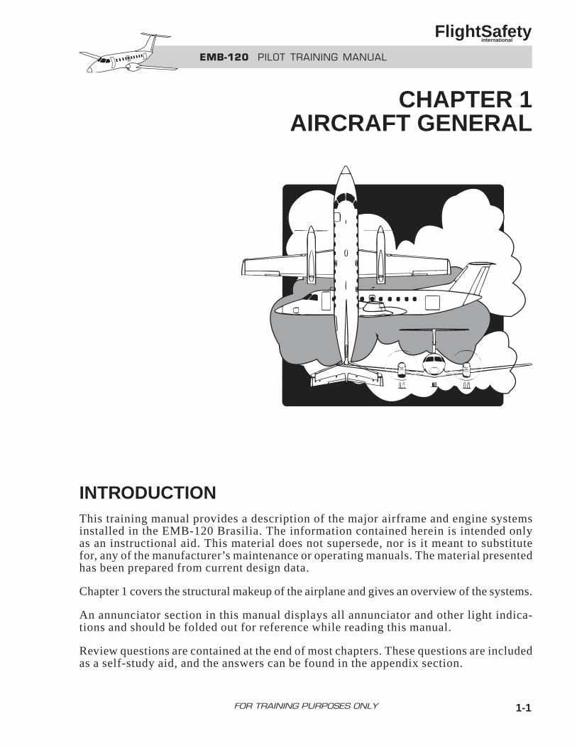
INTRODUCTIONThis training manual provides a description of the major airframe and engine systemsinstalled in the EMB-120 Brasilia. The information contained herein is intended onlyas an instructional aid. This material does not supersede, nor is it meant to substitutefor, any of the manufacturer’s maintenance or operating manuals. The material presentedhas been prepared from current design data.
Chapter 1 covers the structural makeup of the airplane and gives an overview of the systems.
An annunciator section in this manual displays all annunciator and other light indica-tions and should be folded out for reference while reading this manual.
Review questions are contained at the end of most chapters. These questions are includedas a self-study aid, and the answers can be found in the appendix section.
EMB-120 PILOT TRAINING MANUAL
FlightSafety international
CHAPTER 1AIRCRAFT GENERAL
1-1FOR TRAINING PURPOSES ONLY
GENERALThe EMB-120 Brasilia is certified in accor-dance w i th FAR Pa r t 25 a i rwor th ine s sstandards. It is designed for passenger andcargo transportation on typical commercialair carriers. There are three types: RT, ER,and FC.
The minimum crew requirements for operationsin the EMB-120 Brasilia are one pilot and onecopilot. The pilot-in-command must have aBrasilia type rating and meet the requirementsof FAR 61.58 for two-pilot operation. The copi-lot shall possess a multiengine rating and meetthe requirements of FAR 61.55.
STRUCTURES
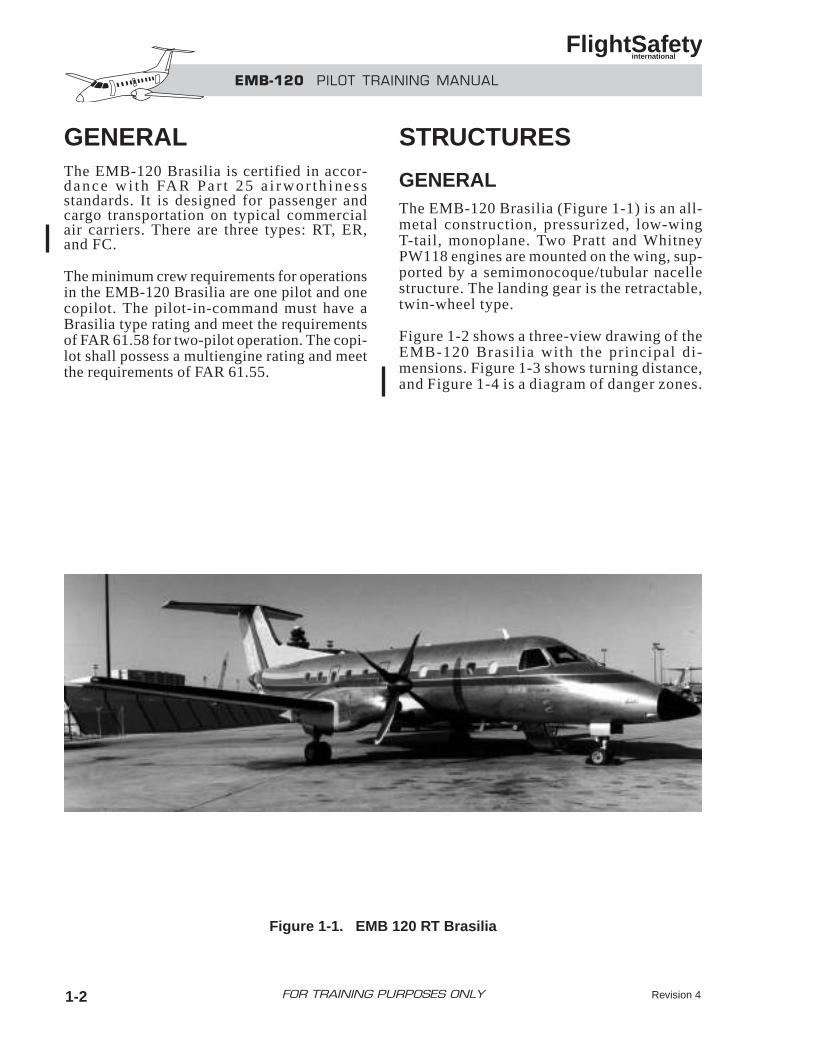
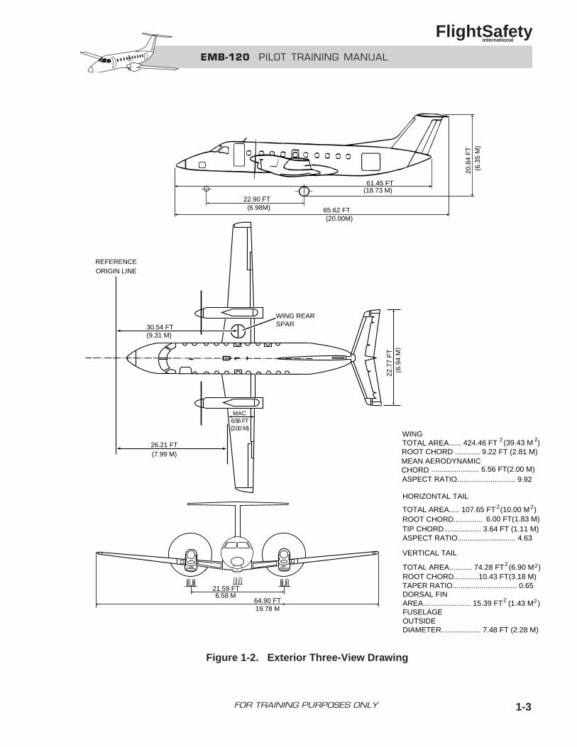
GENERALThe EMB-120 Brasilia (Figure 1-1) is an all-metal construction, pressurized, low-wingT-tail, monoplane. Two Pratt and WhitneyPW118 engines are mounted on the wing, sup-ported by a semimonocoque/tubular nacellestructure. The landing gear is the retractable,twin-wheel type.
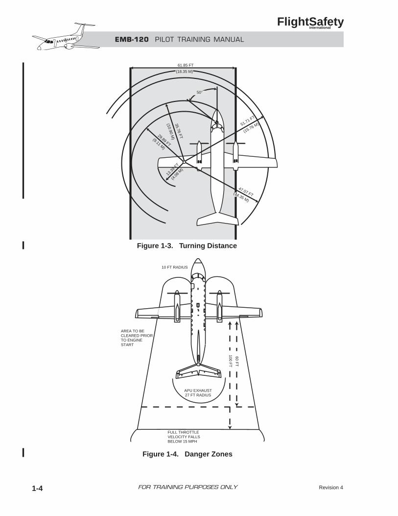
Figure 1-2 shows a three-view drawing of theEMB-120 Brasil ia with the principal di-mensions. Figure 1-3 shows turning distance,and Figure 1-4 is a diagram of danger zones.
EMB-120 PILOT TRAINING MANUAL
FlightSafety international
Revision 41-2 FOR TRAINING PURPOSES ONLY
Figure 1-1. EMB 120 RT Brasilia
EMB-120 PILOT TRAINING MANUAL
FlightSafety international
1-3FOR TRAINING PURPOSES ONLY
61.45 FT(18.73 M)
(20.00M)
(6.98M) 65.62 FT
22.90 FT
(6.3
5 M
)20
.84
FT
)
64.90 FT19.78 M
21.59 FT6.58 M
WINGTOTAL AREA...... 424.46 FT 2 (39.43 M 2)ROOT CHORD ............ 9.22 FT (2.81 M)MEAN AERODYNAMICCHORD ....................... 6.56 FT(2.00 M)ASPECT RATIO............................. 9.92
HORIZONTAL TAIL
TOTAL AREA..... 107.65 FT 2(10.00 M )2
ROOT CHORD.............. 6.00 FT(1.83 M)TIP CHORD.................. 3.64 FT (1.11 M)ASPECT RATIO............................ 4.63
VERTICAL TAIL
TOTAL AREA........... 74.28 FT2 (6.90 M )ROOT CHORD............10.43 FT(3.18 M)TAPER RATIO............................... 0.65DORSAL FINAREA....................... 15.39 FT 2 (1.43 M ) 2
FUSELAGEOUTSIDEDIAMETER................... 7.48 FT (2.28 M)
22.7
7 F
T6.
94 M
(
2
30.54 FT(9.31 M)
WING REARSPAR
MAC6.56 FT(2.00 M)
26.21 FT(7.99 M)
REFERENCEORIGIN LINE
Figure 1-2. Exterior Three-View Drawing
EMB-120 PILOT TRAINING MANUAL
FlightSafety international
Revision 41-4 FOR TRAINING PURPOSES ONLY
61.85 FT
(18.35 M)
50°
51.71 FT
(4.0
8 M
)13
.39
FT
(15.76 M)
47.07 FT(14.35 M)
35.76 FT
(10.90 M)
29.89 FT(9.11 M)
APU EXHAUST27 FT RADIUS
AREA TO BECLEARED PRIORTO ENGINESTART
10 FT RADIUS
FULL THROTTLEVELOCITY FALLSBELOW 15 MPH
60 FT
100 FT
Figure 1-3. Turning Distance
Figure 1-4. Danger Zones
COCKPIT
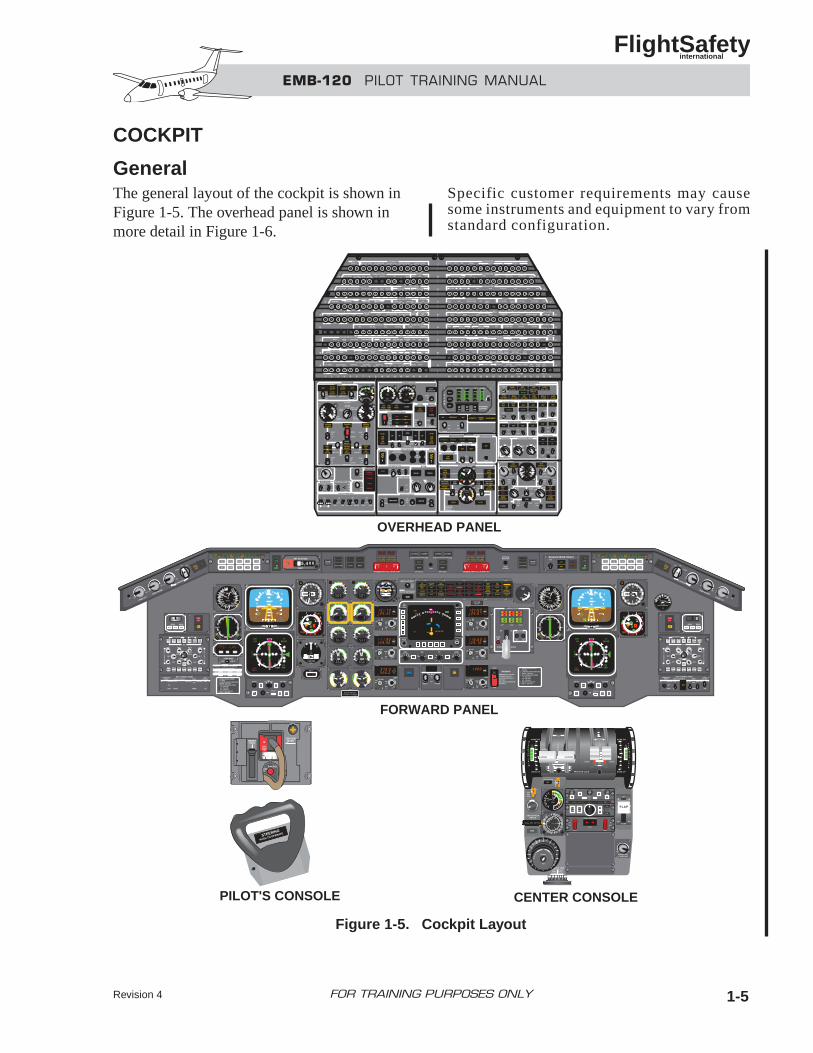
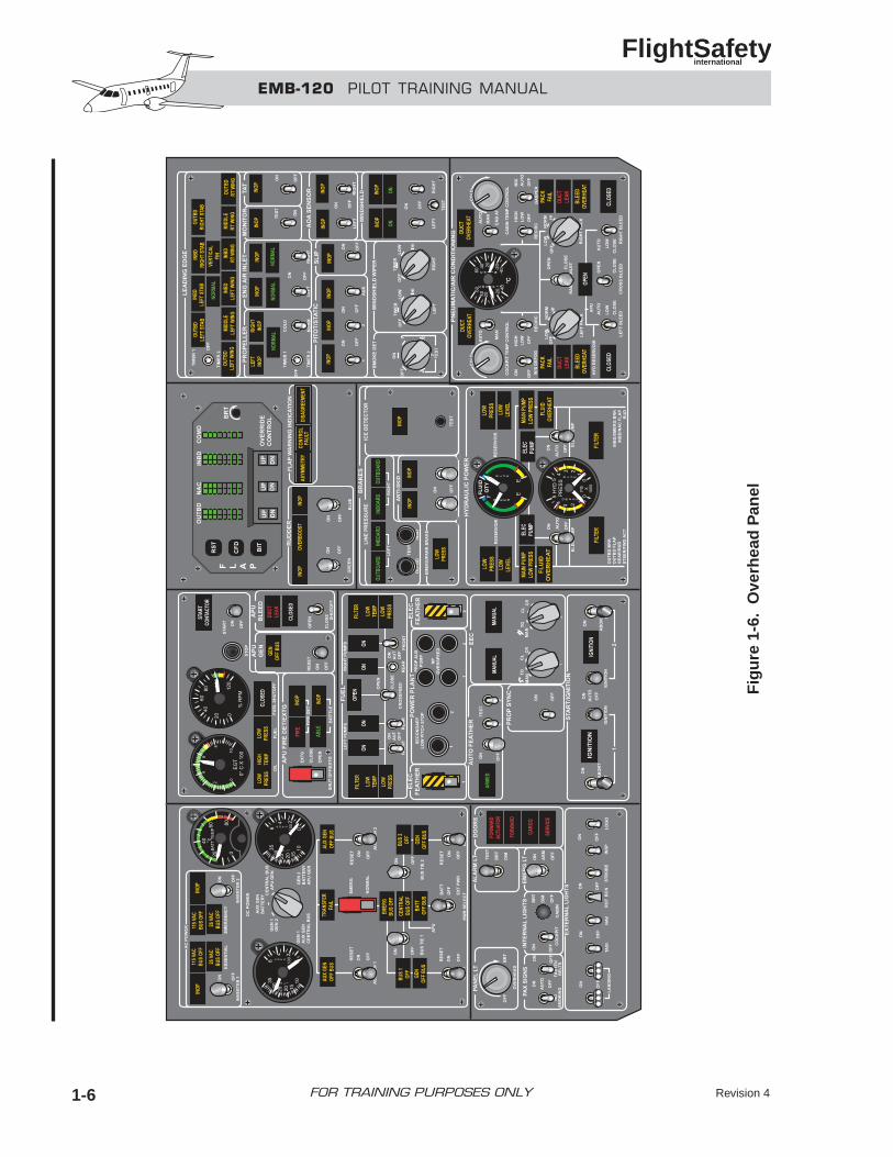
GeneralThe general layout of the cockpit is shown inFigure 1-5. The overhead panel is shown inmore detail in Figure 1-6.
Specific customer requirements may causesome instruments and equipment to vary fromstandard configuration.
EMB-120 PILOT TRAINING MANUAL
FlightSafety international
Revision 4 1-5FOR TRAINING PURPOSES ONLY
OVERHEAD PANEL
FORWARD PANEL
PILOT'S CONSOLE CENTER CONSOLE
Figure 1-5. Cockpit Layout
EMB-120 PILOT TRAINING MANUAL
FlightSafety international
Revision 41-6 FOR TRAINING PURPOSES ONLY
Fig
ure
1-6
. O
verh
ead
Pan
el
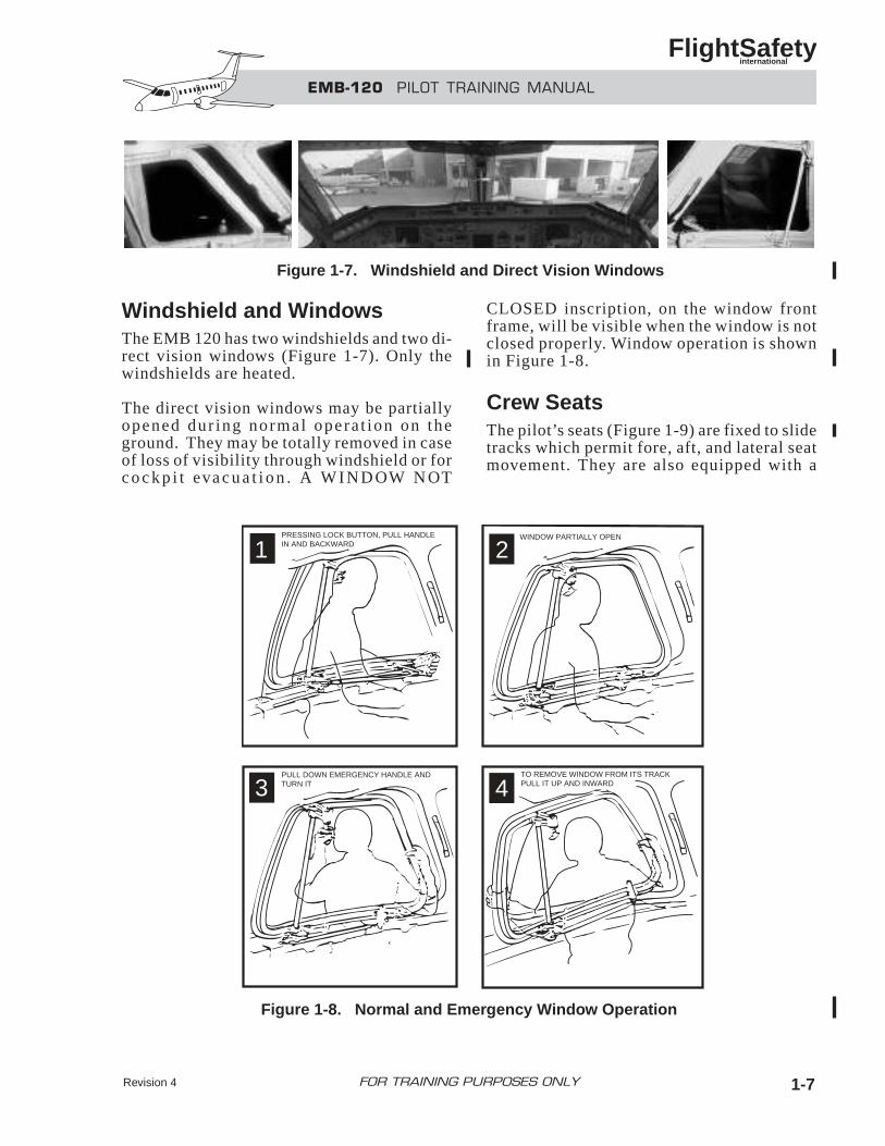
Windshield and WindowsThe EMB 120 has two windshields and two di-rect vision windows (Figure 1-7). Only thewindshields are heated.
The direct vision windows may be partiallyopened dur ing normal opera t ion on theground. They may be totally removed in caseof loss of visibility through windshield or forc o c k p i t eva c u a t i o n . A W I N D OW N OT
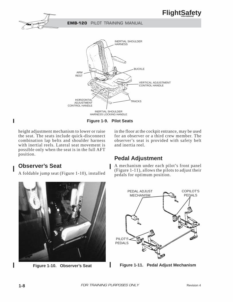
CLOSED inscription, on the window frontframe, will be visible when the window is notclosed properly. Window operation is shownin Figure 1-8.
Crew SeatsThe pilot’s seats (Figure 1-9) are fixed to slidetracks which permit fore, aft, and lateral seatmovement. They are also equipped with a
EMB-120 PILOT TRAINING MANUAL
FlightSafety international
Revision 4 1-7FOR TRAINING PURPOSES ONLY
Figure 1-7. Windshield and Direct Vision Windows
21
43
PRESSING LOCK BUTTON, PULL HANDLEIN AND BACKWARD
WINDOW PARTIALLY OPEN
TO REMOVE WINDOW FROM ITS TRACKPULL IT UP AND INWARD
PULL DOWN EMERGENCY HANDLE ANDTURN IT
Figure 1-8. Normal and Emergency Window Operation
height adjustment mechanism to lower or raisethe seat. The seats include quick-disconnectcombination lap belts and shoulder harnesswith inertial reels. Lateral seat movement ispossible only when the seat is in the full AFTposition.
Observer’s SeatA foldable jump seat (Figure 1-10), installed
in the floor at the cockpit entrance, may be usedfor an observer or a third crew member. Theobserver’s seat is provided with safety beltand inertia reel.
Pedal AdjustmentA mechanism under each pilot’s front panel(Figure 1-11), allows the pilots to adjust theirpedals for optimum position.
EMB-120 PILOT TRAINING MANUAL
FlightSafety international
Revision 41-8 FOR TRAINING PURPOSES ONLY
INERTIAL SHOULDERHARNESS
BUCKLE
VERTICAL ADJUSTMENTCONTROL HANDLE
INERTIAL SHOULDERHARNESS LOCKING HANDLE
TRACKSHORIZONTALADJUSTMENT
CONTROL HANDLE
ARMREST
PILOT'SPEDALS
COPILOT'SPEDALS
PEDAL ADJUSTMECHANISM
Figure 1-9. Pilot Seats
Figure 1-10. Observer’s Seat Figure 1-11. Pedal Adjust Mechanism
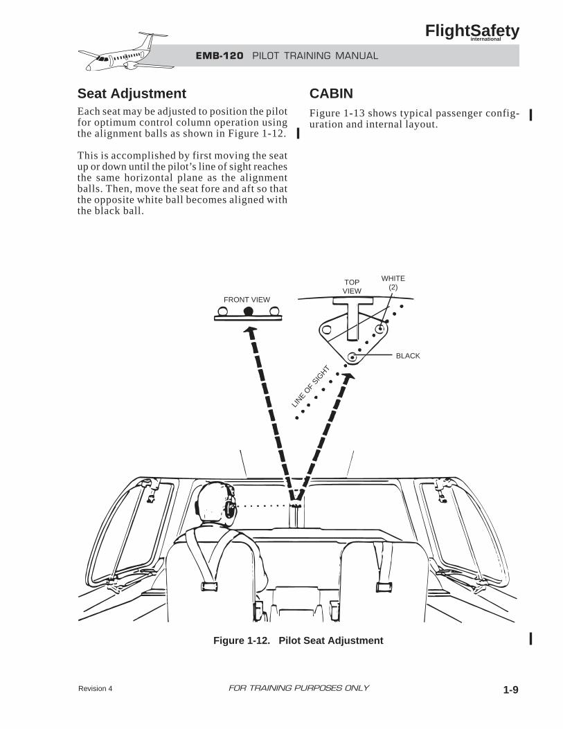
Seat AdjustmentEach seat may be adjusted to position the pilotfor optimum control column operation usingthe alignment balls as shown in Figure 1-12.
This is accomplished by first moving the seatup or down until the pilot’s line of sight reachesthe same horizontal plane as the alignmentballs. Then, move the seat fore and aft so thatthe opposite white ball becomes aligned withthe black ball.
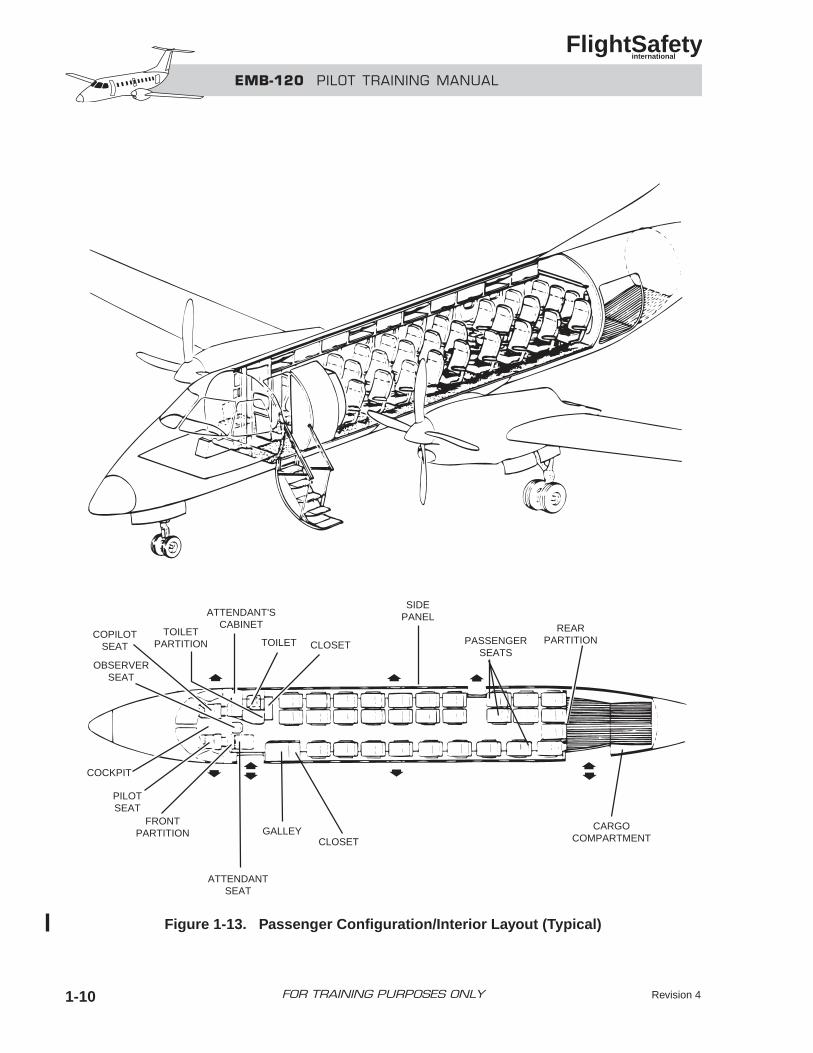
CABINFigure 1-13 shows typical passenger config-uration and internal layout.
EMB-120 PILOT TRAINING MANUAL
FlightSafety international
Revision 4 1-9FOR TRAINING PURPOSES ONLY
LINE O
F SIG
HT
FRONT VIEW
TOPVIEW
WHITE(2)
BLACK
Figure 1-12. Pilot Seat Adjustment
EMB-120 PILOT TRAINING MANUAL
FlightSafety international
Revision 41-10 FOR TRAINING PURPOSES ONLY
Figure 1-13. Passenger Configuration/Interior Layout (Typical)
COPILOTSEAT
OBSERVERSEAT
TOILETPARTITION
ATTENDANT'SCABINET
TOILET CLOSET
SIDEPANEL
PASSENGERSEATS
REARPARTITION
CARGOCOMPARTMENTCLOSET
GALLEY
ATTENDANTSEAT
PILOTSEAT
COCKPIT
FRONTPARTITION
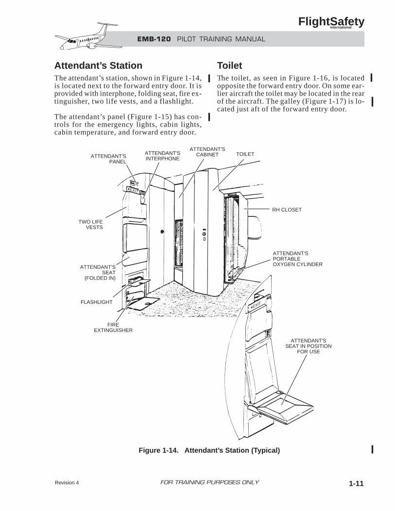
Attendant’s StationThe attendant’s station, shown in Figure 1-14,is located next to the forward entry door. It isprovided with interphone, folding seat, fire ex-tinguisher, two life vests, and a flashlight.
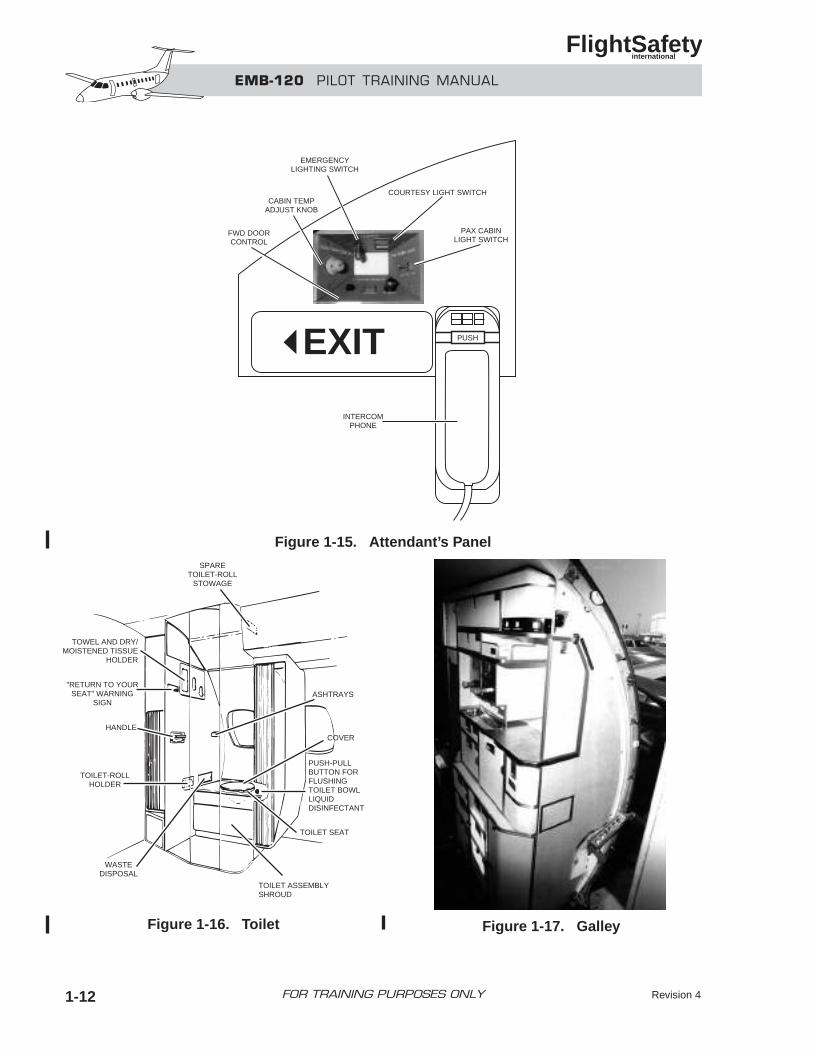
The attendant’s panel (Figure 1-15) has con-trols for the emergency lights, cabin lights,cabin temperature, and forward entry door.
ToiletThe toilet, as seen in Figure 1-16, is locatedopposite the forward entry door. On some ear-lier aircraft the toilet may be located in the rearof the aircraft. The galley (Figure 1-17) is lo-cated just aft of the forward entry door.
EMB-120 PILOT TRAINING MANUAL
FlightSafety international
Revision 4 1-11FOR TRAINING PURPOSES ONLY
FIREEXTINGUISHER
FLASHLIGHT
ATTENDANT'SSEAT
(FOLDED IN)
ATTENDANT'SPANEL
ATTENDANT'SINTERPHONE
ATTENDANT'SCABINET
RH CLOSET
ATTENDANT'SPORTABLEOXYGEN CYLINDER
ATTENDANT'SSEAT IN POSITION
FOR USE
EXIT
EXIT
TOILET
TWO LIFEVESTS
Figure 1-14. Attendant’s Station (Typical)
EMB-120 PILOT TRAINING MANUAL
FlightSafety international
Revision 41-12 FOR TRAINING PURPOSES ONLY
PUSHEXIT
CABIN TEMPADJUST KNOB
EMERGENCYLIGHTING SWITCH
COURTESY LIGHT SWITCH
PAX CABINLIGHT SWITCH
FWD DOORCONTROL
INTERCOMPHONE
SPARETOILET-ROLL
STOWAGE
TOWEL AND DRY/MOISTENED TISSUE
HOLDER
"RETURN TO YOURSEAT" WARNING
SIGN
HANDLE
TOILET-ROLLHOLDER
WASTEDISPOSAL
TOILET ASSEMBLYSHROUD
TOILET SEAT
PUSH-PULLBUTTON FORFLUSHINGTOILET BOWLLIQUIDDISINFECTANT
COVER
ASHTRAYS
Figure 1-15. Attendant’s Panel
Figure 1-16. Toilet Figure 1-17. Galley
DOORS
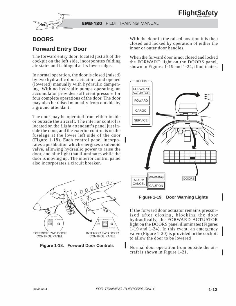
Forward Entry DoorThe forward entry door, located just aft of thecockpit on the left side, incorporates foldingair stairs and is hinged at its lower edge.
In normal operation, the door is closed (raised)by two hydraulic door actuators, and opened(lowered) manually with hydraulic dampen-ing. With no hydraulic pumps operating, anaccumulator provides sufficient pressure forfour complete operations of the door. The doormay also be raised manually from outside bya ground attendant.
The door may be operated from either insideor outside the aircraft. The interior control islocated on the flight attendant’s panel just in-side the door, and the exterior control is on thefuselage at the lower left side of the door(Figure 1-18). Each control panel incorpo-rates a pushbutton which energizes a solenoidvalve, allowing hydraulic power to raise thedoor, and blue light that illuminates while thedoor is moving up. The interior control panelalso incorporates a circuit breaker.
With the door in the raised position it is thenclosed and locked by operation of either theinner or outer door handles.
When the forward door is not closed and lockedthe FORWARD light on the DOORS panel,shown in Figures 1-19 and 1-24, illuminates.
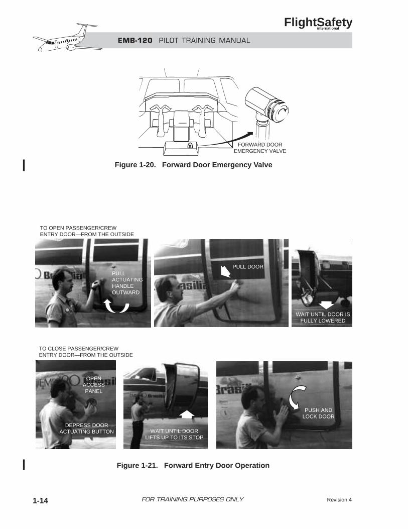
If the forward door actuator remains pressur-i z ed a f t e r c l o s ing , b lock ing t he doo rhydraulically, the FORWARD ACTUATORlight on the DOORS panel illuminates (Figures1-19 and 1-24). In this event, an emergencyvalve (Figure 1-20) is provided in the cockpitto allow the door to be lowered
Normal door operation from outside the air-craft is shown in Figure 1-21.
EMB-120 PILOT TRAINING MANUAL
FlightSafety international
Revision 4 1-13FOR TRAINING PURPOSES ONLY
Figure 1-19. Door Warning Lights
PRESSCLOSEDOOR
FWD DOOR
CONTROL IN TRANSIT
PRESSCLOSEDOOR
CONTROL IN TRANSIT
EXTERIOR FWD DOORCONTROL PANEL
FWD DOOR
INTERIOR FWD DOORCONTROL PANEL
2
DOORSWARNING
CAUTION
ALARMCANCEL
FORWARDACTUATOR
FOWARD
CARGO
SERVICE
DOORS
Figure 1-18. Forward Door Controls
EMB-120 PILOT TRAINING MANUAL
FlightSafety international
Revision 41-14 FOR TRAINING PURPOSES ONLY
FORWARD DOOREMERGENCY VALVE
Figure 1-20. Forward Door Emergency Valve
TO OPEN PASSENGER/CREWENTRY DOOR—FROM THE OUTSIDE
PULLACTUATINGHANDLEOUTWARD
PULL DOOR
WAIT UNTIL DOOR ISFULLY LOWERED
OPENACCESSPANEL
DEPRESS DOORACTUATING BUTTON WAIT UNTIL DOOR
LIFTS UP TO ITS STOP
PUSH ANDLOCK DOOR
TO CLOSE PASSENGER/CREWENTRY DOOR—FROM THE OUTSIDE
Figure 1-21. Forward Entry Door Operation
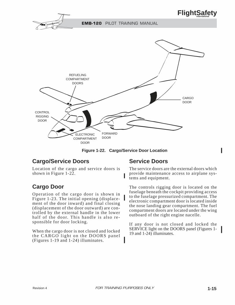
Cargo/Service DoorsLocation of the cargo and service doors isshown in Figure 1-22.
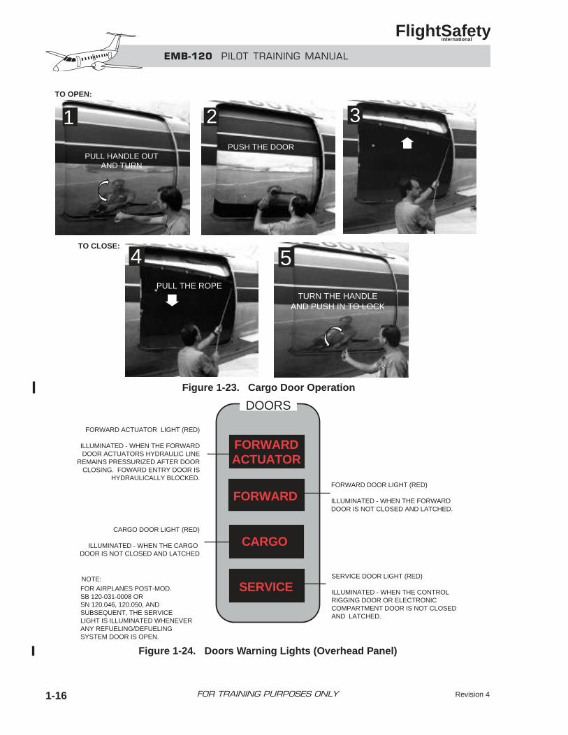
Cargo DoorOperation of the cargo door is shown inFigure 1-23. The initial opening (displace-ment of the door inward) and final closing(displacement of the door outward) are con-trolled by the external handle in the lowerhalf of the door. This handle is also re-sponsible for door locking.
When the cargo door is not closed and lockedthe CARGO l igh t on the DOORS pane l(Figures 1-19 and 1-24) illuminates.
Service DoorsThe service doors are the external doors whichprovide maintenance access to airplane sys-tems and equipment.
The controls rigging door is located on thefuselage beneath the cockpit providing accessto the fuselage pressurized compartment. Theelectronic compartment door is located insidethe nose landing gear compartment. The fuelcompartment doors are located under the wingoutboard of the right engine nacelle.
If any door is not closed and locked theSERVICE light on the DOORS panel (Figures 1-19 and 1-24) illuminates.
EMB-120 PILOT TRAINING MANUAL
FlightSafety international
Revision 4 1-15FOR TRAINING PURPOSES ONLY
CARGODOOR
FORWARDDOOR
ELECTRONICCOMPARTMENT
DOOR
CONTROLRIGGING
DOOR
REFUELINGCOMPARTMENT
DOORS
Figure 1-22. Cargo/Service Door Location
EMB-120 PILOT TRAINING MANUAL
FlightSafety international
Revision 41-16 FOR TRAINING PURPOSES ONLY
TO OPEN:
PUSH THE DOOR
2 3
PULL THE ROPE
4
TURN THE HANDLEAND PUSH IN TO LOCK
5
PULL HANDLE OUTAND TURN
1
TO CLOSE:
DOORS
FORWARD DOOR LIGHT (RED)
ILLUMINATED - WHEN THE FORWARDDOOR IS NOT CLOSED AND LATCHED.
SERVICE DOOR LIGHT (RED)
ILLUMINATED - WHEN THE CONTROLRIGGING DOOR OR ELECTRONICCOMPARTMENT DOOR IS NOT CLOSEDAND LATCHED.
NOTE:FOR AIRPLANES POST-MOD. SB 120-031-0008 ORSN 120.046, 120.050, AND SUBSEQUENT, THE SERVICE LIGHT IS ILLUMINATED WHENEVER ANY REFUELING/DEFUELING SYSTEM DOOR IS OPEN.
FORWARD ACTUATOR LIGHT (RED)
ILLUMINATED - WHEN THE FORWARDDOOR ACTUATORS HYDRAULIC LINE
REMAINS PRESSURIZED AFTER DOORCLOSING. FOWARD ENTRY DOOR IS
HYDRAULICALLY BLOCKED.
CARGO DOOR LIGHT (RED)
ILLUMINATED - WHEN THE CARGO DOOR IS NOT CLOSED AND LATCHED
FORWARDACTUATOR
FORWARD
CARGO
SERVICE
Figure 1-23. Cargo Door Operation
Figure 1-24. Doors Warning Lights (Overhead Panel)
EMERGENCY EQUIPMENT
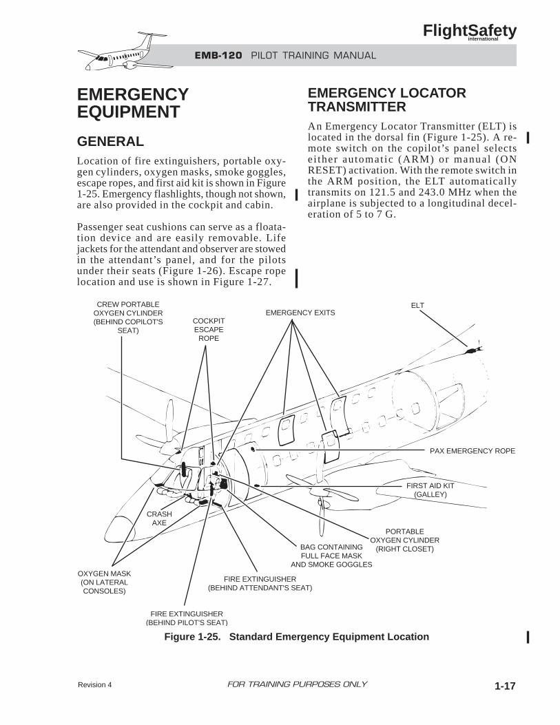
GENERALLocation of fire extinguishers, portable oxy-gen cylinders, oxygen masks, smoke goggles,escape ropes, and first aid kit is shown in Figure1-25. Emergency flashlights, though not shown,are also provided in the cockpit and cabin.
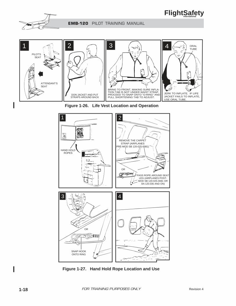
Passenger seat cushions can serve as a floata-tion device and are easily removable. Lifejackets for the attendant and observer are stowedin the attendant’s panel, and for the pilotsunder their seats (Figure 1-26). Escape ropelocation and use is shown in Figure 1-27.
EMERGENCY LOCATORTRANSMITTERAn Emergency Locator Transmitter (ELT) islocated in the dorsal fin (Figure 1-25). A re-mote switch on the copilot’s panel selectsei ther automat ic (ARM) or manual (ONRESET) activation. With the remote switch inthe ARM position, the ELT automaticallytransmits on 121.5 and 243.0 MHz when theairplane is subjected to a longitudinal decel-eration of 5 to 7 G.
EMB-120 PILOT TRAINING MANUAL
FlightSafety international
Revision 4 1-17FOR TRAINING PURPOSES ONLY
CREW PORTABLEOXYGEN CYLINDER(BEHIND COPILOT'S
SEAT)COCKPITESCAPE
ROPE
EMERGENCY EXITSELT
OXYGEN MASK(ON LATERALCONSOLES)
CRASHAXE
FIRE EXTINGUISHER(BEHIND PILOT'S SEAT)
FIRE EXTINGUISHER(BEHIND ATTENDANT'S SEAT)
BAG CONTAININGFULL FACE MASK
AND SMOKE GOGGLES
PORTABLEOXYGEN CYLINDER
(RIGHT CLOSET)
FIRST AID KIT(GALLEY)
PAX EMERGENCY ROPE
Figure 1-25. Standard Emergency Equipment Location
EMB-120 PILOT TRAINING MANUAL
FlightSafety international
Revision 41-18 FOR TRAINING PURPOSES ONLY
4
JERK TO INFLATE. IF LIFEJACKET FAILS TO INFLATE,USE ORAL TUBE.
ORALTUBE
2
DON JACKET AND PUTSTRAPS AROUND BACK
3
BRING TO FRONT, MAKING SURE INFLA-TION TAB IS NOT UNDER WAIST STRAP.PROCEED TO SNAP ONTO "O-RING" ANDPULL SHORTENING TAB TO ADJUST.
1PILOT'S
SEAT
ATTENDANT'SSEAT
HAND HOLDROPES
REMOVE THE CARPETSTRAP (AIRPLANES
PRE-MOD SB 120-025-0081)
PASS ROPE AROUND SEATLEG (AIRPLANES POST-
MOD SB 120-025-0081 ORSN 120.035 AND ON)
OR
OR
SNAP HOOKONTO RING
1 2
3 4
Figure 1-26. Life Vest Location and Operation
Figure 1-27. Hand Hold Rope Location and Use
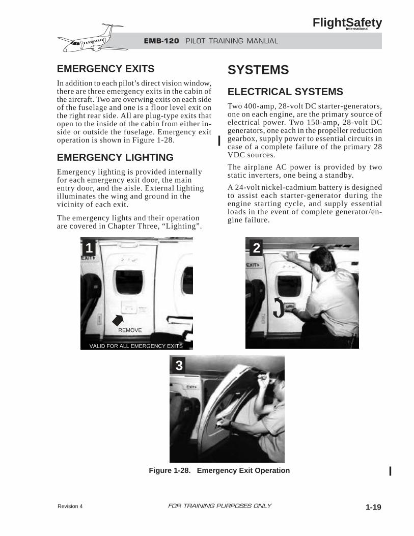
EMERGENCY EXITSIn addition to each pilot’s direct vision window,there are three emergency exits in the cabin ofthe aircraft. Two are overwing exits on each sideof the fuselage and one is a floor level exit onthe right rear side. All are plug-type exits thatopen to the inside of the cabin from either in-side or outside the fuselage. Emergency exitoperation is shown in Figure 1-28.
EMERGENCY LIGHTINGEmergency lighting is provided internallyfor each emergency exit door, the mainentry door, and the aisle. External lightingilluminates the wing and ground in thevicinity of each exit.
The emergency lights and their operationare covered in Chapter Three, “Lighting”.
SYSTEMS
ELECTRICAL SYSTEMSTwo 400-amp, 28-volt DC starter-generators,one on each engine, are the primary source ofelectrical power. Two 150-amp, 28-volt DCgenerators, one each in the propeller reductiongearbox, supply power to essential circuits incase of a complete failure of the primary 28VDC sources.
The airplane AC power is provided by twostatic inverters, one being a standby.
A 24-volt nickel-cadmium battery is designedto assist each starter-generator during theengine starting cycle, and supply essentialloads in the event of complete generator/en-gine failure.
EMB-120 PILOT TRAINING MANUAL
FlightSafety international
Revision 4 1-19FOR TRAINING PURPOSES ONLY
1 2
3
VALID FOR ALL EMERGENCY EXITS
REMOVE
Figure 1-28. Emergency Exit Operation
An emergency battery is available as a backupfor selected loads and to provide emergencypower for both the standby horizon and gen-erator control units (GCUs).
A starter-generator installed on the APU, iden-tical to the main generators, is used to start theAPU. It may be used to provide electricalpower to all buses on the ground, and forstandby power in flight.
FUEL SYSTEMThe fuel system is made up of two tanks, onein each wing. Each wing tank is made up oftwo independent cells separated by the wheel-well. These inboard and outboard cells areinterconnected by tubes for gravity fuel trans-fer. Fuel is supplied to the engine by pumpsinstalled in a collector tank located in the low-est region of each inboard fuel cell. Each wingtank has a usable capacity of 437 US Gal.
Each engine is supplied independently fromits wing tank. A crossfeed line allows eitherwing tank to supply both engines simultane-ously. Gages for monitoring fuel flow and fuelquantity are located on the fuel managementpanel in the cockpit.
The aircraft may be gravity fueled using over-wing fillercaps, and manually defueled. Apressurized system is provided for faster fu-eling/defueling.
AUXILIARY POWER UNITThe APU, located in the tail cone, is a gas tur-bine engine used to supply pressurized air andelectrical power to the airplane.
POWERPLANTTwo Pratt and Whitney PW118 or PW118Aturboprop engines, both flat rated at 1800SHP, are mounted on the wings. The engine isa three-shaft, two-spool gas generator with afree power turbine.
Engine airflow is straight-through with airentering an intake below the propeller spinner,then through an S-duct to the engine. This S-duct provides inertial separation and protectionin the event of foreign object ingestion.
PropellerEach engine is equipped with a HamiltonSundstrand model 14 RF-9, four-blade, con-s t an t speed , r eve r s ib le , fu l l f ea the r ingpropeller. Automatic feathering and propellersynchronization systems are installed.
FIRE PROTECTIONFire detectors installed in the engine acces-sories section, wheelwell, pipe zones and APUcompartment provide fire or overheat warning.
The engine fire control panel, installed on thecenter glareshield panel, is provided with bot-tle discharge ability and INOP lights, shutoffvalve position indicators, fire warning lights,extinguishing handles, and a test button. TheAPU fire control panel on the overhead APUCONTROL panel, provides the means for APUfire detection and extinguishing.
A smoke detection system is installed for usewhen the a i rplane is conver ted to cargoconfiguration.
ICE AND RAIN PROTECTIONAn electrical anti-icing system protects the leftand right windshields, pitot/static tubes, staticports, angle of attack, and side slip sensors.
Electrical deicing system protects the pro-peller blades to permit unrestricted operationinto known icing conditions. The wings, sta-bilizers, vertical fin, and engine air inlets areprotected by inflatable deicers.
The rain removal system consists of two in-dependent two-speed wipers, one on eachwindshield.
EMB-120 PILOT TRAINING MANUAL
FlightSafety international
Revision 41-20 FOR TRAINING PURPOSES ONLY
AIR CONDITIONING ANDPRESSURIZATIONThe air-conditioning and pressurization sys-tem provides conditioned pressurized air to thecockpit and passenger cabin. The system is op-erated using bleed air from either the enginesor the APU.
The cockpit and passenger cabin are suppliedby separate air ducting with cross-connectingcapabilities. Temperature of the two zones isindependently controlled.
The cabin pressure control, designed to main-tain a 7 psi cabin/ambient pressure differential,maintains the cabin at sea level pressure up toan altitude of 16,800 ft. Control is accom-p l i shed by an e l ec t ropneuma t i c va lve(automatic mode) or by a pneumatic valve(manual mode).
HYDRAULIC SYSTEMHydraulic power is provided by two indepen-dent systems. Each system is powered by amain pump, driven by the left or right propellergearbox. DC powered electrical pumps providebackup pressure for each system. Two pres-surized hydraulic reservoirs are arranged sothat leakage in either of the systems will notaffect operation of the other. Each hydraulicreservoir is equipped with transmitters andswitches that display system status on the HY-DRAULIC POWER PANEL located on thecockpit overhead panel.
LANDING GEAR AND BRAKESThe landing gear is a conventional tricycle,dual-wheel, forward retracting type.
Three modes are provided for operation of thelanding gear:
• Normal hydraulic retraction and extension
• Alternate electrical override extension
• Emergency free-fall extension with man-ual release of the uplocks.
Nosewheel steering is controlled through asteering handle on the pilot’s left console.Limited nosewheel steering is available withthe rudder pedals.
A normal brake system is actuated by con-ventional means through the pilot or copilotrudder pedals and controlled by a dual anti-skidsystem.
An emergency brake sys tem is ac tuatedthrough a handle and control valve. Pressureto the brakes is proportional to handle dis-placement.
FLIGHT CONTROLSFlight controls are operated by conventionalcontrol wheels, columns, and rudder pedals forpilot and copilot. They are normally inter-connec t ed and j o in t l y ope ra t ed . I n anemergency, control wheels and columns maybe disconnected between the pilot and copi-lot, rendering the airplane controllable byeither. Pedals are independently adjustable, al-lowing comfortable operation.
The elevators and ailerons are mechanicallyactuated. The rudder is hydraulically actu-ated with a mechanical back-up.
The flaps, divided into three panels per wing,are hydraulically actuated.
Elevator and aileron trim is by mechanical ac-tuators to trim tabs. Rudder trim is hydraulic.
AVIONICS
Flight instrumentsConventional air data instruments (airspeed,altimeter, and vertical speed indicator) areprovided with separate pitot/static sources forpilot and copilot.
An independent standby attitude indicator onthe center panel, and a standby compass inthe top of the windshield center post, provideback-up attitude and heading information.
EMB-120 PILOT TRAINING MANUAL
FlightSafety international
Revision 4 1-21FOR TRAINING PURPOSES ONLY
NavigationThe navigation system includes the followingequipment:
• Electronic flight instrument system(EFIS)
• Two independent attitude and headingreference systems (AHRS)
• Two radiomagnetic indicators (RMI)
• Two distance measuring equipment(DME) systems
• Two VHF/NAV(VOR/ILS/MB) radios
• Two ATC transponders
• One automatic direction finder (ADF)
• One radio altimeter system
The EFIS displays consist of two electronic at-t i t ude d i r ec to r i nd i ca to r s (EADI) , twoelectronic horizontal situation indicators(EHSI), and a multifunction display (MFD).The EADI and EHSI are color cathode-raytube displays.
The AHRS provides attitude and heading sig-nals to the EFIS and autopilot/flight director;pitch and roll angle to the weather radar; andturn rate and normal acceleration data to theautopilot, if required.
Radar is displayed on the multifunction displayand each EHSI when in the ARC or map mode.
AutoflightThe autoflight system is a fully integratedthree-axis dual flight control system includ-ing manual electric trim. It is divided into twogeneral systems:
• Flight director system
• Autopilot system
Available functions include heading, altitude andairspeed control, VOR/ILS approach coupling,glide-slope operation, and go-around mode.
CommunicationThe communication system includes:
• Interphone for communication betweenpersonnel in the cockpit, and flight crewmembers and cabin/ramp personnel
• Passenger address system for commu-nication between flight crew membersand passengers
• VHF for air-to-air and air-to-groundcommunication.
The airplane is equipped with a cockpit voicerecorder.
OXYGENThe airplane is equipped with a conventionalgaseous oxygen system. One oxygen cylin-der supplies low-pressure oxygen to both thecrew and passenger systems. The crew systemconsists of three quick-donning masks. Thepassenger system consists of continuous flowmasks in dispensing units, installed in theaisle ceiling. The units open automatically,when cabin altitude exceeds 14,000 feet, ormanually by a switch installed on the controlstand in the cockpit.
Other related equipment includes portableoxygen cylinders, smoke goggles, and fullface masks.
PUBLICATIONSThe FAA-approved Airplane Flight Manual(AFM) is a required flight item. It contains thelimitations, operating procedures, performancedata pertinent to takeoffs and landings, andweight and balance data. It does not containenroute performance information. The AFMalways takes precedence over any other pub-lication.
The EMB 120 Operating Manual contains ex-panded descriptions of the airplane systemsand operating procedures. It contains enrouteflight planning information as well as sometakeoff and landing performance information.
EMB-120 PILOT TRAINING MANUAL
FlightSafety international
Revision 41-22 FOR TRAINING PURPOSES ONLY
The EMB120 check l i s t (QRH– QuickReferrence Handbook) contains abbreviatedope ra t i ng p rocedu re s and abb rev i a t edperformance data. If any doubt exists or if theconditions are not covered by the checklist, theAFM must be consulted.
The EMB 120 Weight and Balance Manualcontains detailed infomation in the form oftables and diagrams. However, it is not requiredto be in the airplane as the basic empty weightand moment and means of determining thecenter-of-gravity location are all containedin the AFM.
EMB-120 PILOT TRAINING MANUAL
FlightSafety international
Revision 4 1-23FOR TRAINING PURPOSES ONLY
1. The EMB 120 is certified under:A. FAR Part 25B. FAR Part 61C. FAR Part 91D. Brazilian CAA Paragraph 7
2. The EMB 120 has how many generators?A. 2B. 3C. 4D. 5
3. The EMB 120 forward entry door may be:A. Raised and lowered electricallyB. Raised and lowered manuallyC. Raised hydraulically—lowered man-
uallyD. Both B and C
4. The EMB 120 direct vision windows maybe removed by the crew.A. TrueB. False
5. If the main entry door is not securelyclosed and locked:A. An alarm will sound at the flight at-
tendants station.B. A door open light will illuminate in
the cockpit.C. A door solenoid will prevent engine
start.D. There is no indication of this situation.
6. How many cycles can the forward entrydoor be operated without recharging itsaccumulator?A. 1B. 2C. 3D. 4
EMB-120 PILOT TRAINING MANUAL
FlightSafety international
Revision 41-24 FOR TRAINING PURPOSES ONLY
QUESTIONS
EMB-120 PILOT TRAINING MANUAL
FlightSafety international
FOR TRAINING PURPOSES ONLYRevision 4 2-i
CHAPTER 2ELECTRICAL POWER SYSTEMS
CONTENTS
Page
INTRODUCTION ................................................................................................................... 2-1
GENERAL............................................................................................................................... 2-1
DC POWER............................................................................................................................. 2-2
Components ..................................................................................................................... 2-2
Distribution ...................................................................................................................... 2-6
Control and Monitoring ................................................................................................... 2-9
AC POWER........................................................................................................................... 2-12
Components ................................................................................................................... 2-12
Distribution .................................................................................................................... 2-12
Control and Monitoring ................................................................................................. 2-12
ELECTRICAL SYSTEM OPERATION............................................................................... 2-12
Normal Mode................................................................................................................. 2-15
Emergency Mode ........................................................................................................... 2-20
Overcurrent Protection................................................................................................... 2-22
PRE MOD SB 120-024-00051 ELECTRICAL SYSTEM DIFFERENCES ........................ 2-29
ELECTRICAL CONTROL PANEL SUMMARY ................................................................ 2-37
QUESTIONS......................................................................................................................... 2-39
Revision 4 2-iii
ILLUSTRATIONS
Figure Title Page
2-1 Electrical Component Location................................................................................ 2-2
2-2 Battery Location....................................................................................................... 2-2
2-3 Battery Temperature Gage........................................................................................ 2-3
2-4 Backup Battery Switch............................................................................................. 2-4
2-5 External Power Receptacle....................................................................................... 2-5
2-6 Power Select Switch ................................................................................................. 2-5
2-7 Central DC Power Distribution ................................................................................ 2-6
2-8 Auxiliary DC Power System .................................................................................... 2-7
2-9 Backup DC Power System ....................................................................................... 2-8
2-10 Radio Master System................................................................................................ 2-9
2-11 Electrical Control Panel—DC System ................................................................... 2-11
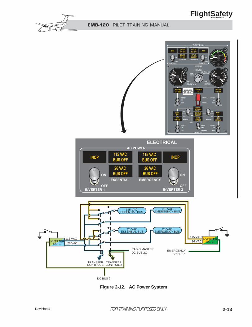
2-12 AC Power System .................................................................................................. 2-13
2-13 Electrical Power System......................................................................................... 2-14
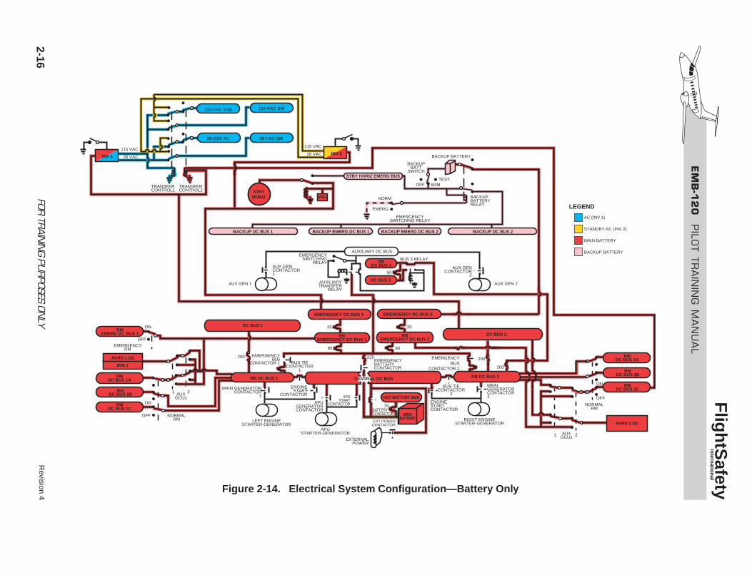
2-14 Electrical System Configuration—Battery Only.................................................... 2-16
2-15 Electrical System Configuration—External Power................................................ 2-17
2-16 Electrical System Configuration—APU Generator ............................................... 2-18
2-17 Electrical System Configuration—Single Engine.................................................. 2-19
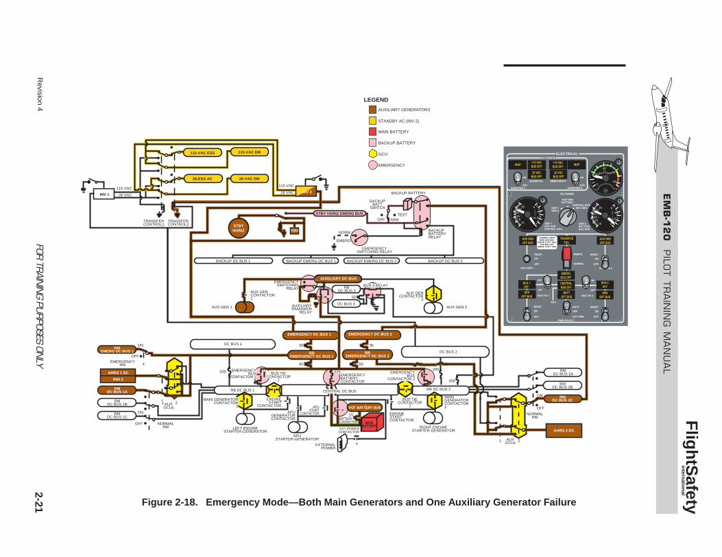
2-18 Emergency Mode—Both Main Generatorsand One Auxiliary Generator Failure..................................................................... 2-21
2-19 Emergency Mode—Total Generator Failure .......................................................... 2-23
2-20 Overcurrent Case 1: Short Circuit, Central DC Bus............................................... 2-24
2-21 Overcurrent Case 2: Short Circuit, Relay Box DC Bus 1 ...................................... 2-26
2-22 Overcurrent Case 3: Short Circuit, Relay Box DC Bus 2 ...................................... 2-28
FOR TRAINING PURPOSES ONLY
EMB-120 PILOT TRAINING MANUAL
FlightSafety international
Revision 42-iv
2-23 Circuit-Breaker Panel............................................................................................. 2-35
2-24 Electrical Control Panel ......................................................................................... 2-36
TABLE
Table Title Page
2-1 Electrical Bus Equipment Distribution................................................................... 2-30
FOR TRAINING PURPOSES ONLY
EMB-120 PILOT TRAINING MANUAL
FlightSafety international
EMB-120 PILOT TRAINING MANUAL
FlightSafety international
2-1
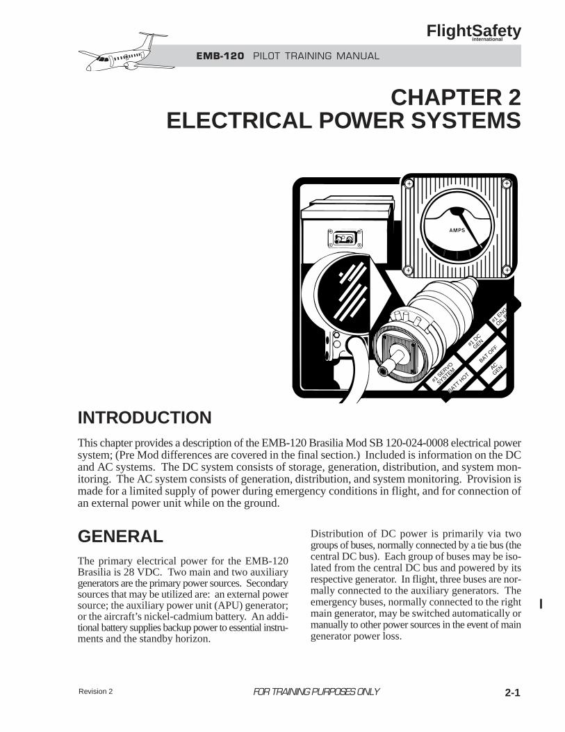
INTRODUCTIONThis chapter provides a description of the EMB-120 Brasilia Mod SB 120-024-0008 electrical powersystem; (Pre Mod differences are covered in the final section.) Included is information on the DCand AC systems. The DC system consists of storage, generation, distribution, and system mon-itoring. The AC system consists of generation, distribution, and system monitoring. Provision ismade for a limited supply of power during emergency conditions in flight, and for connection ofan external power unit while on the ground.
GENERALThe primary electrical power for the EMB-120Brasilia is 28 VDC. Two main and two auxiliarygenerators are the primary power sources. Secondarysources that may be utilized are: an external powersource; the auxiliary power unit (APU) generator;or the aircraft’s nickel-cadmium battery. An addi-tional battery supplies backup power to essential instru-ments and the standby horizon.
Distribution of DC power is primarily via twogroups of buses, normally connected by a tie bus (thecentral DC bus). Each group of buses may be iso-lated from the central DC bus and powered by itsrespective generator. In flight, three buses are nor-mally connected to the auxiliary generators. Theemergency buses, normally connected to the rightmain generator, may be switched automatically ormanually to other power sources in the event of maingenerator power loss.
#1 S
ERVO
SYSTEM
BATT HOT
BAT OFF
AC
GEN
#1 D
C
GEN
#1 E
NG
OIL PL
FOR TRAINING PURPOSES ONLY
CHAPTER 2ELECTRICAL POWER SYSTEMS
Revision 2
2-2
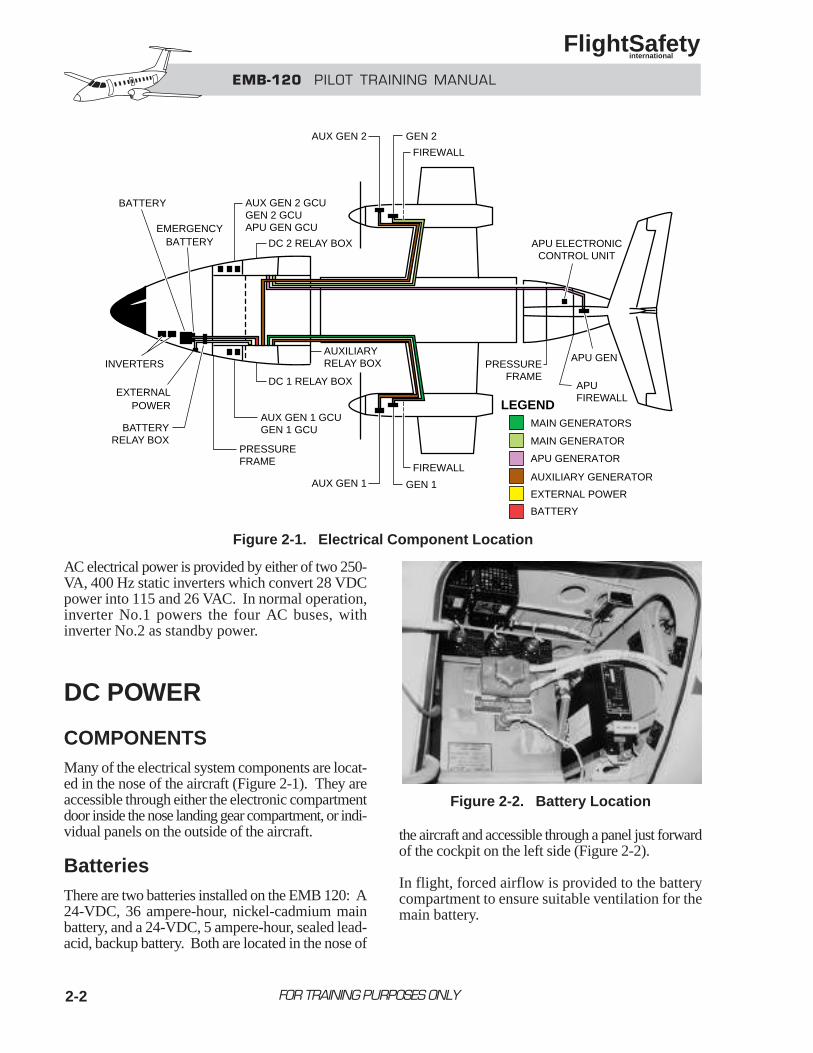
AC electrical power is provided by either of two 250-VA, 400 Hz static inverters which convert 28 VDCpower into 115 and 26 VAC. In normal operation,inverter No.1 powers the four AC buses, withinverter No.2 as standby power.
DC POWER
COMPONENTSMany of the electrical system components are locat-ed in the nose of the aircraft (Figure 2-1). They areaccessible through either the electronic compartmentdoor inside the nose landing gear compartment, or indi-vidual panels on the outside of the aircraft.
BatteriesThere are two batteries installed on the EMB 120: A24-VDC, 36 ampere-hour, nickel-cadmium mainbattery, and a 24-VDC, 5 ampere-hour, sealed lead-acid, backup battery. Both are located in the nose of
the aircraft and accessible through a panel just forwardof the cockpit on the left side (Figure 2-2).
In flight, forced airflow is provided to the batterycompartment to ensure suitable ventilation for themain battery.
FOR TRAINING PURPOSES ONLY
EMB-120 PILOT TRAINING MANUAL
FlightSafety international
APUFIREWALL
APU GEN
APU ELECTRONICCONTROL UNIT
PRESSUREFRAME
PRESSUREFRAME
LEGENDMAIN GENERATORS
MAIN GENERATOR
APU GENERATOR
AUXILIARY GENERATOR
EXTERNAL POWER
EXTERNALPOWER
BATTERY
FIREWALL
GEN 1
FIREWALL
GEN 2
AUX GEN 1
AUX GEN 2
AUX GEN 1 GCUGEN 1 GCU
AUXILIARYRELAY BOX
AUX GEN 2 GCUGEN 2 GCUAPU GEN GCU
DC 1 RELAY BOX
DC 2 RELAY BOX
BATTERYRELAY BOX
INVERTERS
BATTERY
EMERGENCYBATTERY
Figure 2-2. Battery Location
Figure 2-1. Electrical Component Location
Revision 4 2-3
Main BatteryThe main battery is connected in parallel with themain generators. It is designed to power each gen-erator during the engine starting cycle when exter-nal power is not available. It will also supplyessential loads for approximately 30 minutes in theevent of loss of all generators.
The battery is always connected to the hot battery bus.
Positioning the PWR SELECT switch to BATT ener-gizes the battery contactor closed, connecting thebattery to the central DC bus. The battery contac-tor is provided with a protective device that openswhen the current from the central DC bus to the bat-tery exceeds 500 amps.
On the ground with the battery as the only powersource, a safety circuit inhibits power to the recir-culation fans, gasper fan, and ground cooling fans.
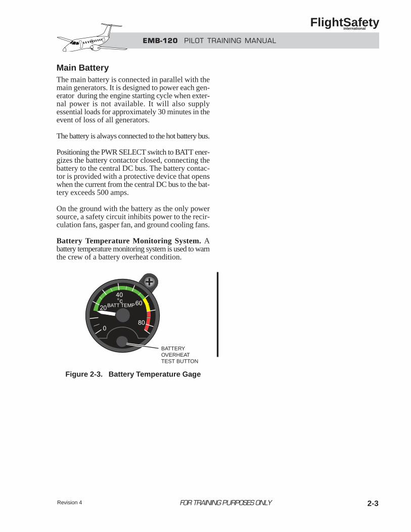
Battery Temperature Monitoring System. Abattery temperature monitoring system is used to warnthe crew of a battery overheat condition.
FOR TRAINING PURPOSES ONLY
EMB-120 PILOT TRAINING MANUAL
FlightSafety international
BATTERYOVERHEATTEST BUTTON
Figure 2-3. Battery Temperature Gage
EMB-120 PILOT TRAINING MANUAL
FlightSafety international
Revision 42-4
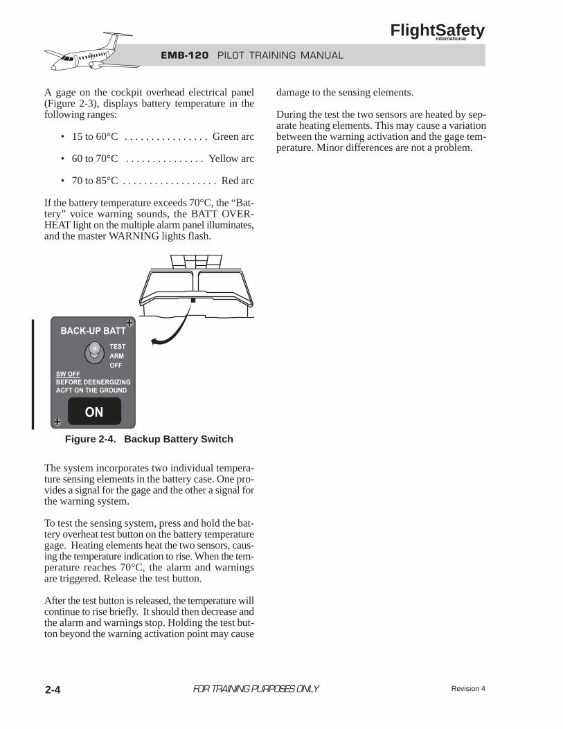
A gage on the cockpit overhead electrical panel(Figure 2-3), displays battery temperature in thefollowing ranges:
• 15 to 60°C . . . . . . . . . . . . . . . . Green arc
• 60 to 70°C . . . . . . . . . . . . . . . Yellow arc
• 70 to 85°C . . . . . . . . . . . . . . . . . . Red arc
If the battery temperature exceeds 70°C, the “Bat-tery” voice warning sounds, the BATT OVER-HEAT light on the multiple alarm panel illuminates,and the master WARNING lights flash.
The system incorporates two individual tempera-ture sensing elements in the battery case. One pro-vides a signal for the gage and the other a signal forthe warning system.
To test the sensing system, press and hold the bat-tery overheat test button on the battery temperaturegage. Heating elements heat the two sensors, caus-ing the temperature indication to rise. When the tem-perature reaches 70°C, the alarm and warningsare triggered. Release the test button.
After the test button is released, the temperature willcontinue to rise briefly. It should then decrease andthe alarm and warnings stop. Holding the test but-ton beyond the warning activation point may cause
damage to the sensing elements.
During the test the two sensors are heated by sep-arate heating elements. This may cause a variationbetween the warning activation and the gage tem-perature. Minor differences are not a problem.
FOR TRAINING PURPOSES ONLY
Figure 2-4. Backup Battery Switch
2-5FOR TRAINING PURPOSES ONLY
EMB-120 PILOT TRAINING MANUAL
FlightSafety international
Backup Battery
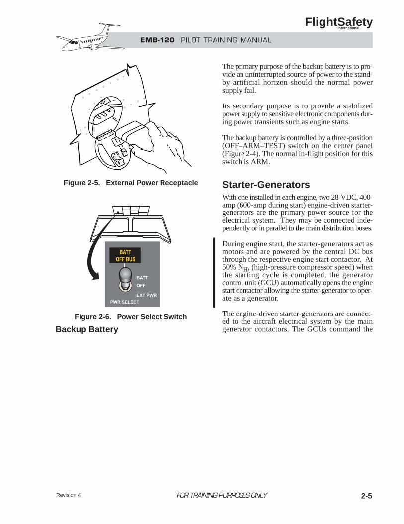
The primary purpose of the backup battery is to pro-vide an uninterrupted source of power to the stand-by artificial horizon should the normal powersupply fail.
Its secondary purpose is to provide a stabilizedpower supply to sensitive electronic components dur-ing power transients such as engine starts.
The backup battery is controlled by a three-position(OFF–ARM–TEST) switch on the center panel(Figure 2-4). The normal in-flight position for thisswitch is ARM.
Starter-GeneratorsWith one installed in each engine, two 28-VDC, 400-amp (600-amp during start) engine-driven starter-generators are the primary power source for theelectrical system. They may be connected inde-pendently or in parallel to the main distribution buses.
During engine start, the starter-generators act asmotors and are powered by the central DC busthrough the respective engine start contactor. At50% NH, (high-pressure compressor speed) whenthe starting cycle is completed, the generatorcontrol unit (GCU) automatically opens the enginestart contactor allowing the starter-generator to oper-ate as a generator.
The engine-driven starter-generators are connect-ed to the aircraft electrical system by the maingenerator contactors. The GCUs command the
Figure 2-5. External Power Receptacle
Figure 2-6. Power Select Switch
Revision 4
Revision 42-6
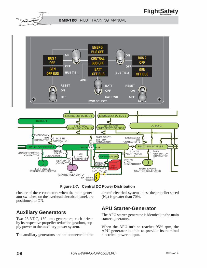
closure of these contactors when the main gener-ator switches, on the overhead electrical panel, arepositioned to ON.
Auxiliary GeneratorsTwo 28-VDC, 150-amp generators, each drivenby its respective propeller reduction gearbox, sup-ply power to the auxiliary power system.
The auxiliary generators are not connected to the
aircraft electrical system unless the propeller speed(NP) is greater than 70%.
APU Starter-GeneratorThe APU starter-generator is identical to the mainstarter-generators.
When the APU turbine reaches 95% rpm, theAPU generator is able to provide its nominalelectrical power output.
FOR TRAINING PURPOSES ONLY
EMB-120 PILOT TRAINING MANUAL
FlightSafety international
EMERGENCY DC BUS 2EMERGENCY DC BUS 1
RELAY BOXEMERGENCY DC BUS 2
RELAY BOXEMERGENCY DC BUS 1
RELAY BOX DC BUS 2
RIGHT ENGINESTARTER-GENERATOR
MAIN GENERATORCONTACTOR2ENGINE
STARTCONTACTOR 2
ENGINESTART
CONTACTOR 1APU
STARTCONTACTOR
EMERGENCYBATTERYCONTACTOR
BATTERYCONTACTOR
HOT BATTERY BUS
MAINBATTERY
EXTERNALPOWER
EXT POWERCONTACTOR
CENTRAL DC BUS
BUS TIECONTACTOR
2
BUS TIECONTACTOR
1
APUGENERATORCONTACTOR
APUSTARTER-GENERATOR
LEFT ENGINESTARTER-GENERATOR
MAIN GENERATORCONTACTOR
1
EMERGENCYBUS
CONTACTOR
DC BUS 2
DC BUS 1
RELAY BOX DC BUS 1
EMERGENCYBUS
CONTACTOR 2
Figure 2-7. Central DC Power Distribution
EMB-120 PILOT TRAINING MANUAL
FlightSafety international
2-7
The main purpose of the APU generator is to sub-stitute for the external power unit on the ground. Itmay also be used in parallel with the battery to powera starter-generator during engine start.
In flight, if required, the APU generator may be usedin parallel with the main generators.
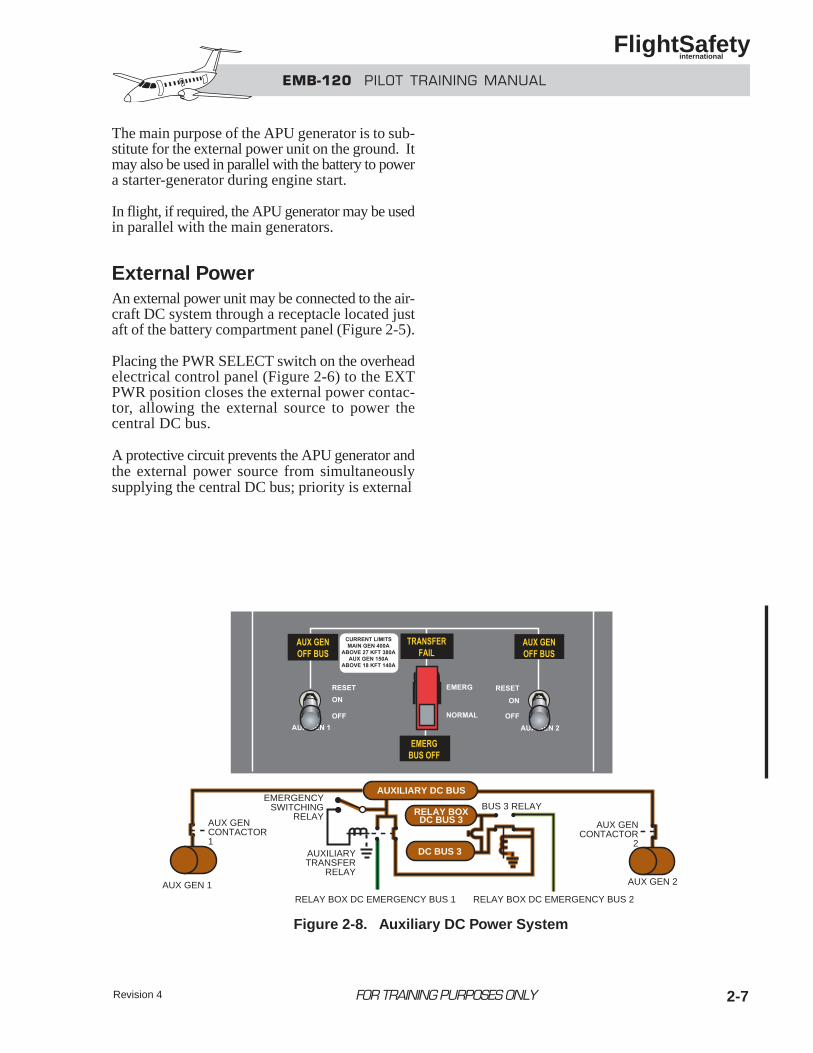
External PowerAn external power unit may be connected to the air-craft DC system through a receptacle located justaft of the battery compartment panel (Figure 2-5).
Placing the PWR SELECT switch on the overheadelectrical control panel (Figure 2-6) to the EXTPWR position closes the external power contac-tor, allowing the external source to power thecentral DC bus.
A protective circuit prevents the APU generator andthe external power source from simultaneouslysupplying the central DC bus; priority is external
FOR TRAINING PURPOSES ONLY
AUXILIARY DC BUS
RELAY BOXDC BUS 3
DC BUS 3AUXILIARYTRANSFER
RELAY
EMERGENCYSWITCHING
RELAYAUX GENCONTACTOR1
AUX GENCONTACTOR
2
AUX GEN 1 AUX GEN 2
BUS 3 RELAY
RELAY BOX DC EMERGENCY BUS 2RELAY BOX DC EMERGENCY BUS 1
Figure 2-8. Auxiliary DC Power System
Revision 4

Revision 42-8
power. A similar circuit also prevents the maingenerator and the external power source fromsimultaneously supplying the central DC bus; pri-ority in this case is the main generator.
An overvoltage relay protects the central DC bus ifexternal power exceeds 32 VDC. In this condition, theexternal power contactor will open, disconnecting theexternal power from the central DC bus.
The external power voltage may be monitored on
the left voltammeter by setting the voltammeter selec-tor to the CENTRAL BUS/APU GEN position.
DISTRIBUTION
Central DC SystemDirect current is distributed throughout the air-craft as shown in Figure 2-7.
Each main generator is normally connected to the
FOR TRAINING PURPOSES ONLY
EMB-120 PILOT TRAINING MANUAL
FlightSafety international
VSUSTANDBYHORIZON BACKUP
BATTERYRELAY
BACKUP BATTERY
BACKUPBATT
SWITCH
OFFTEST
ARM
NORM
AUX GEN 1/2 GCUGEN 1/2 GCU
EMERGEMERGENCY
SWITCHING RELAY
EMERGENCYDC BUS 2
EMERGENCYDC BUS 1
STBY HORIZ EMERG BUS
BACKUP DC BUS 1 BACKUP EMERG DC BUS 1 BACKUP EMERG DC BUS 2 BACKUP DC BUS 2
DC BUS 1 EMERG DC BUS 1 EMERG DC BUS 2 DC BUS 2
• AURAL WARNING• AHRS 1• NH AND T6 ENG 1 INDICATIONS• RCCBs FOR: L HYD AUX PUMP
L PROP HEATERRECIRC FAN 1L WSHLD DEICEGASPER FANTAXI LIGHTL GRND COOL FAN
• AHRS 2• NH AND T6 ENG 2 INDICATIONS• RCCBs FOR: R HYD AUX PUMP
R PROP HEATERRECIRC FAN 2R LDG LIGHTR WSHLD DEICER GRND COOL FAN
• EEC 1• IGNITION LIGHT 1• RCCB FOR L AUX FEATHER PUMP
• CLOCK/CHRONO• EEC 2• IGNITION LIGHT 2• RCCBs FOR: R AUX FEATHER PUMP
L LDG LIGHT
Figure 2-9. Backup DC Power System
Revision 4 2-9FOR TRAINING PURPOSES ONLY
EMB-120 PILOT TRAINING MANUAL
FlightSafety international
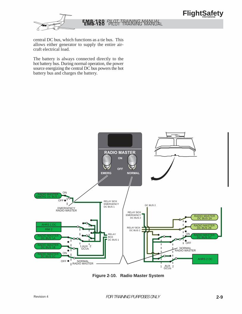
central DC bus, which functions as a tie bus. Thisallows either generator to supply the entire air-craft electrical load.
The battery is always connected directly to thehot battery bus. During normal operation, the powersource energizing the central DC bus powers the hotbattery bus and charges the battery.
EMB-120 PILOT TRAINING MANUAL
RELAY BOXEMERGENCYDC BUS 1
RELAY BOXEMERGENCY
DC BUS 2
RELAYBOXDC BUS 1
RELAY BOXDC BUS 2
DC BUS 2
RADIO MASTERDC BUS 2A
RADIO MASTERDC BUS 2B
RADIO MASTERDC BUS 2C
ON
OFF
NORMALRADIO MASTER
AHRS 2 DC
1 2AUXGCUs
ON
ON
OFF
OFF
EMERGENCYRADIO MASTER
NORMALRADIO MASTER
RADIO MASTEREMERG DC BUS 1
RADIO MASTERDC BUS 1A
RADIO MASTERDC BUS 1B
RADIO MASTERDC BUS 1C
AHRS 1 DC
RMI 2
1 2 AUXGCUs
Figure 2-10. Radio Master System
EMB-120 PILOT TRAINING MANUAL
FlightSafety international
2-10
Auxiliary DC SystemWhen propeller speed (NP) reaches 70%, the aux-iliary generator control unit (GCU) connects the aux-iliary generator to the auxiliary DC bus (Figure 2-8).(The auxiliary generators are the only power sourcefor the auxiliary DC bus.)
When powered, the auxiliary DC bus, energizes arelay that shifts the bus 3 contactor, switching bothrelay box DC bus 3 and DC bus 3 from relay boxDC bus 2 to the auxiliary DC bus.
When NP drops below 70%, the auxiliary GCU dis-connects the generator from the auxiliary DC bus. Ifthe auxiliary DC bus loses power (both auxiliarygenerators below 70%), both relay box DC bus 3 andDC bus 3 switch back to relay box DC bus 2.
The auxiliary GCUs also switch the primary nav-igation equipment (AHRS 1, AHRS 2, RMI 2,and radio master DC bus 1A and 2C) to the emer-gency buses.
FOR TRAINING PURPOSES ONLY Revision 4
Revision 4 2-11FOR TRAINING PURPOSES ONLY
EMB-120 PILOT TRAINING MANUAL
FlightSafety international
Figure 2-11. Electrical Control Panel—DC System
2-12 FOR TRAINING PURPOSES ONLY
EMB-120 PILOT TRAINING MANUAL
FlightSafety international
Backup DC Power SystemThe backup power system (Figure 2-9) consists ofthe backup battery, the BACKUP BATT switchon the center panel, and the following buses:
• Backup DC bus 1
• Backup DC bus 2
• Backup emergency DC bus 1
• Backup emergency DC bus 2
• Standby horizon emergency bus
Through one-way diodes, each backup bus is joint-ly connected to essential instruments normallypowered by one of the four main DC buses (DC bus1, DC bus 2, emergency DC bus 1, emergency DCbus 2).
The backup battery system operates in the normalmode whenever the BACKUP BATT switch is in theARM position (and the electrical DC system isoperating in the normal mode). In this mode, all fivebuses are in a powered, standby status. The back-up battery is charged by emergency DC bus 2, andthe standby attitude indicator is powered by emer-gency DC bus 1.
If the voltage on any of the four main DC buses dropsbelow the voltage of their respective backup buses,power will be supplied to essential instrumentsthrough the backup buses.
The backup bus circuit breakers are all rated oneamp higher than the corresponding main DC buscircuit breakers. As a result, the main bus circuitbreakers on the overhead panel open before the back-up bus circuit breakers. This feature assists faultdetection by the pilot.
Revision 4
EMB-120 PILOT TRAINING MANUAL
FlightSafety international
Revision 4 2-13FOR TRAINING PURPOSES ONLY
RADIO MASTERDC BUS 2C
EMERGENCYDC BUS 1
DC BUS 2
115 VAC
26 VAC
115 VAC
26 VAC
TRANSFERCONTROL 1
TRANSFERCONTROL 2
115-VACESSENTIAL BUS
26-VACESSENTIAL BUS
115-VACEMERGENCY BUS
26-VACEMERGENCY BUS
INVERTERNO. 2INVERTER
NO. 1
Figure 2-12. AC Power System
EM
B-1
20
PILO
T T
RA
ININ
G M
AN
UA
L
Flig
htS
afety
intern
ation
al
2-14FOR
TRAIN
ING PU
RPOSES ON
LYR
evision 4
115 VAC
26 VAC
115 VAC
26 VAC
TRANSFERCONTROL 1
TRANSFERCONTROL 2
115-VACESSENTIAL BUS
26-VACESSENTIAL BUS
115-VACEMERGENCY BUS
26-VACEMERGENCY BUS
VSUSTANDBYHORIZON
BACKUP DC BUS 1 BACKUP EMERG DC BUS 1 BACKUP EMERG DC BUS 2 BACKUP DC BUS 2
BACKUPBATTERYRELAY
BACKUP BATTERY
BACKUPBATT
SWITCH
OFFTEST
ARM
NORM
50
35
80
200 225 200
15
200
80
35
EMERG
EMERGENCYSWITCHING RELAY
AUXILIARY DC BUS
RELAY BOXDC BUS 3
DC BUS 3AUXILIARYTRANSFER
RELAY
EMERGENCYSWITCHING
RELAYAUX GENCONTACTOR1
AUX GENCONTACTOR
2
AUX GEN 1 AUX GEN 2
BUS 3 RELAY
EMERGENCY DC BUS 2EMERGENCY DC BUS 1
RELAY BOXEMERGENCY DC BUS 2
RELAY BOXEMERGENCY DC BUS 1
RELAY BOX DC BUS 2
RIGHT ENGINESTARTER-GENERATOR
MAIN GENERATORCONTACTOR2
ENGINESTARTCONTACTOR
ENGINESTART
CONTACTOR APUSTART
CONTACTOR
EMERGENCYBATTERYCONTACTOR
BATTERYCONTACTOR
HOT BATTERY BUS
MAINBATTERY
RADIO MASTERDC BUS 2A
RADIO MASTERDC BUS 2B
RADIO MASTERDC BUS 2C
ON
OFF
NORMALRADIO MASTER
AHRS 2 DC
1 2AUXGCUsEXTERNAL
POWER
EXT POWERCONTACTOR
CENTRAL DC BUS
BUS TIECONTACTOR
2
BUS TIECONTACTOR
1
APUGENERATORCONTACTOR
APUSTARTER-GENERATOR
LEFT ENGINESTARTER-GENERATOR
MAIN GENERATORCONTACTOR
1
EMERGENCYBUS
CONTACTOR 1EMERGENCY
BUSCONTACTOR 2
ON
ON
OFF
OFF
EMERGENCYRADIO MASTER
NORMALRADIO MASTER
RADIO MASTEREMERG DC BUS 1
RADIO MASTERDC BUS 1A
RADIO MASTERDC BUS 1B
RADIO MASTERDC BUS 1C
AHRS 1 DC
RMI 2
1 2 AUXGCUs
LEFT MAIN DC GENERATOR
RIGHT MAIN DC GENERATOR
APU GENERATOR
AUXILIARY GENERATORS
EXTERNAL POWER
AC (INVERTER NO. 1)
STANDBY AC (INVERTER NO. 2)
MAIN BATTERY
BACKUP BATTERY
STBY HORIZ EMERG BUS
INVERTERNO. 2INVERTER
NO. 1
DC BUS 2
DC BUS 1
RELAY BOX DC BUS 1
LEGEND
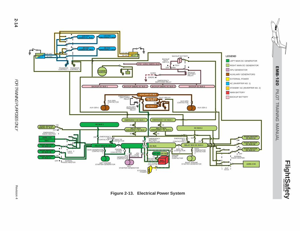
Figure 2-13. Electrical Power System
EMB-120 PILOT TRAINING MANUAL
FlightSafety international
Radio Master SystemDuring the engine starting cycle, bus voltage tran-sients may cause damage to communication and nav-igation instruments. To avoid this, the radio masterswitches allow the pilot to turn off the avionics dur-ing engine start.
There are two radio master switches, onelabeled EMERG and the other labeled NORMAL(Figure 2-10).
The radio master system consists of the radio mas-ter switches, six normal radio master buses, and oneemergency radio master bus.
With both radio master switches in the ON position,the three corresponding relays are deenergized.This connects DC power to the radio master system.
When the switches are in the OFF position, the relaysare energized and power is removed from the radiomaster system.
CONTROL AND MONITORINGControl of the DC electrical system is accom-plished automatically through the five generator con-trol units (GCUs), and manually by switch positionon the overhead electrical control panel.
Monitoring of the electrical system is through thegages and indicator lights on the overhead electri-cal control panel.
GCUsThe main/APU starter-generators and the auxiliarygenerator are controlled by individual GCUs. Thesemultifunction units also provide electrical faultprotection.
Functions of the starter-generator GCUs are asfollows:
• Initiates start cycle:
• Closes start contactor
• Energizes ignition circuit
• Energizes return solenoid to empty draincollector (EPA) tank
• Allows up to 600 amps for generator-aided cross start
• Provides overspeed protection in eventof sheared shaft
• Cancels start cycle at 50% RPM:
• Opens start contactor
• Deenergizes ignition circuit
• Deenergizes EPA return solenoid
• Enables the generator function
• Regulates generator output between 26 and30 VDC (Normal 28.5 VDC)
• Overvoltage protection (> 32 VDC)
• Overcurrent protection (> 400 amps)
• Reverse current protection
• Generator field over excitation protection
• Paralleling protection (maintains generatorloads within 10%)
2-15FOR TRAINING PURPOSES ONLYRevision 4
EM
B-1
20
PILO
T T
RA
ININ
G M
AN
UA
L
Flig
htS
afety
intern
ation
al
2-16FOR
TRAIN
ING PU
RPOSES ON
LYR
evision 4
115-VAC ESS
26-ESS AC
115-VAC EM
26-VAC EM
VSUSTBYHORIZ
BACKUP DC BUS 1 BACKUP EMERG DC BUS 1 BACKUP EMERG DC BUS 2 BACKUP DC BUS 2
BACKUPBATTERYRELAY
BACKUP BATTERY
BACKUPBATT
SWITCH
OFFTEST
ARM
NORM
115 VAC
26 VAC
115 VAC
26 VAC
TRANSFERCONTROL1
TRANSFERCONTROL2
50
35
80
200 225 200
15
200
80
35
EMERG
EMERGENCYSWITCHING RELAY
AUXILIARY DC BUS
RBDC BUS 3
DC BUS 3AUXILIARYTRANSFER
RELAY
EMERGENCYSWITCHING
RELAYAUX GENCONTACTOR1
AUX GENCONTACTOR
2
AUX GEN 1 AUX GEN 2
BUS 3 RELAY
EMERGENCY DC BUS 2EMERGENCY DC BUS 1
RBEMERGENCY DC BUS 2
RBEMERGENCY DC BUS 1
RB DC BUS 2
RIGHT ENGINESTARTER-GENERATOR
MAIN GENERATORCONTACTOR2
ENGINESTARTCONTACTOR
ENGINESTART
CONTACTOR APUSTART
CONTACTOR
EMERGENCYBATTERYCONTACTOR
BATTERYCONTACTOR
HOT BATTERY BUS
MAINBATTERY
RMDC BUS 2A
RMDC BUS 2B
RMDC BUS 2C
ON
OFF
NORMALRM
AHRS 2 DC
1 2AUXGCUsEXTERNAL
POWER
EXT POWERCONTACTOR
CENTRAL DC BUS
BUS TIECONTACTOR
2
BUS TIECONTACTOR
1
APUGENERATORCONTACTOR
APUSTARTER-GENERATOR
LEFT ENGINESTARTER-GENERATOR
MAIN GENERATORCONTACTOR
1
EMERGENCYBUS
CONTACTOR 1
ON
ON
OFF
OFF
EMERGENCYRM
NORMALRM
RMEMERG DC BUS 1
RMDC BUS 1A
RMDC BUS 1B
RMDC BUS 1C
AHRS 1 DC
RMI 2
1 2 AUXGCUs
STBY HORIZ EMERG BUS
DC BUS 2
DC BUS 1
RB DC BUS 1
INV 2INV 1
AC (INV 1)
STANDBY AC (INV 2)
MAIN BATTERY
BACKUP BATTERY
LEGEND
EMERGENCYBUS
CONTACTOR 2
Figure 2-14. Electrical System Configuration—Battery Only
EM
B-1
20
PILO
T T
RA
ININ
G M
AN
UA
L
Flig
htS
afety
intern
ation
al2-17FOR
TRAIN
ING PU
RPOSES ON
LYR
evision 4
115-VAC ESS
26-ESS AC
115-VAC EM
26-VAC EM
VSUSTBYHORIZ
BACKUP DC BUS 1 BACKUP EMERG DC BUS 1 BACKUP EMERG DC BUS 2 BACKUP DC BUS 2
BACKUPBATTERYRELAY
BACKUP BATTERY
BACKUPBATT
SWITCH
OFFTEST
ARM
NORM
115 VAC
26 VAC
115 VAC
26 VAC
TRANSFERCONTROL1
TRANSFERCONTROL2
50
35
80
200 225 200
15
200
80
35
EMERG
EMERGENCYSWITCHING RELAY
AUXILIARY DC BUS
RBDC BUS 3
DC BUS 3AUXILIARYTRANSFER
RELAY
EMERGENCYSWITCHING
RELAYAUX GENCONTACTOR1
AUX GENCONTACTOR
2
AUX GEN 1 AUX GEN 2
BUS 3 RELAY
EMERGENCY DC BUS 2EMERGENCY DC BUS 1
RBEMERGENCY DC BUS 2
RBEMERGENCY DC BUS 1
RIGHT ENGINESTARTER-GENERATOR
MAIN GENERATORCONTACTOR2
ENGINESTARTCONTACTOR
ENGINESTART
CONTACTOR APUSTART
CONTACTOR
EMERGENCYBATTERYCONTACTOR
BATTERYCONTACTOR
HOT BATTERY BUS
MAINBATTERY
RMDC BUS 2A
RMDC BUS 2B
RMDC BUS 2C
ON
OFF
NORMALRM
AHRS 2 DC
1 2AUXGCUsEXTERNAL
POWER
EXT POWERCONTACTOR
CENTRAL DC BUS
BUS TIECONTACTOR
2
BUS TIECONTACTOR
1
APUGENERATORCONTACTOR
APUSTARTER-GENERATOR
LEFT ENGINESTARTER-GENERATOR
MAIN GENERATORCONTACTOR
1
EMERGENCYBUS
CONTACTOR 1
ON
ON
OFF
OFF
EMERGENCYRM
NORMALRM
RMEMERG DC BUS 1
RMDC BUS 1A
RMDC BUS 1B
RMDC BUS 1C
AHRS 1 DC
RMI 2
1 2 AUXGCUs
STBY HORIZ EMERG BUS
DC BUS 2
DC BUS 1
RB DC BUS 1
INV 2INV 1
AC (INV 1)
STANDBY AC (INV 2)
MAIN BATTERY
BACKUP BATTERY
EXT PWR
LEGEND
RB DC BUS 2
EMERGENCYBUS
CONTACTOR 2
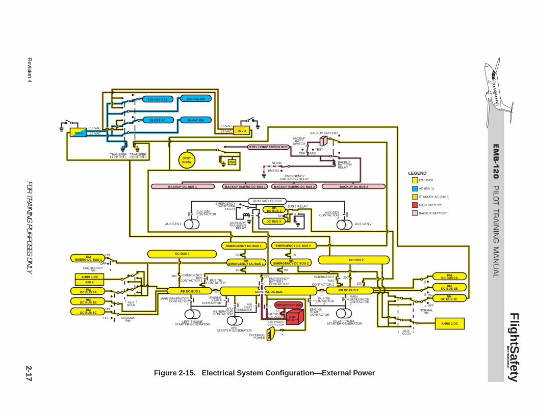
Figure 2-15. Electrical System Configuration—External Power
EM
B-1
20
PILO
T T
RA
ININ
G M
AN
UA
L
Flig
htS
afety
intern
ation
al
2-18FOR
TRAIN
ING PU
RPOSES ON
LYR
evision 4
115-VAC ESS
26-ESS AC
115-VAC EM
26-VAC EM
VSUSTBYHORIZ
BACKUP DC BUS 1 BACKUP EMERG DC BUS 1 BACKUP EMERG DC BUS 2 BACKUP DC BUS 2
BACKUPBATTERYRELAY
BACKUP BATTERY
BACKUPBATT
SWITCH
OFFTEST
ARM
NORM
115 VAC
26 VAC
115 VAC
26 VAC
TRANSFERCONTROL1
TRANSFERCONTROL2
50
35
80
200 225 200
15
200
80
35
EMERG
EMERGENCYSWITCHING RELAY
AUXILIARY DC BUS
RBDC BUS 3
DC BUS 3AUXILIARYTRANSFER
RELAY
EMERGENCYSWITCHING
RELAYAUX GENCONTACTOR1
AUX GENCONTACTOR
2
AUX GEN 1 AUX GEN 2
BUS 3 RELAY
EMERGENCY DC BUS 2EMERGENCY DC BUS 1
RBEMERGENCY DC BUS 2
RBEMERGENCY DC BUS 1
RIGHT ENGINESTARTER-GENERATOR
MAIN GENERATORCONTACTOR2
ENGINESTARTCONTACTOR
ENGINESTART
CONTACTOR APUSTART
CONTACTOR
EMERGENCYBATTERYCONTACTOR
BATTERYCONTACTOR
HOT BATTERY BUS
MAINBATTERY
RMDC BUS 2A
RMDC BUS 2B
RMDC BUS 2C
ON
OFF
NORMALRM
AHRS 2 DC
1 2AUXGCUsEXTERNAL
POWER
EXT POWERCONTACTOR
CENTRAL DC BUS
BUS TIECONTACTOR
2
BUS TIECONTACTOR
1
APUGENERATORCONTACTOR
APUSTARTER-GENERATOR
LEFT ENGINESTARTER-GENERATOR
MAIN GENERATORCONTACTOR
1
EMERGENCYBUS
CONTACTOR 1
ON
ON
OFF
OFF
EMERGENCYRM
NORMALRM
RMEMERG DC BUS 1
RMDC BUS 1A
RMDC BUS 1B
RMDC BUS 1C
AHRS 1 DC
RMI 2
1 2 AUX
GCUs
STBY HORIZ EMERG BUS
DC BUS 2
DC BUS 1
RB DC BUS 1
INV 2INV 1
AC (INV 1)
STANDBY AC (INV 2)
MAIN BATTERY
BACKUP BATTERY
APU GEN
LEGEND
RB DC BUS 2
EMERGENCYBUS
CONTACTOR 2
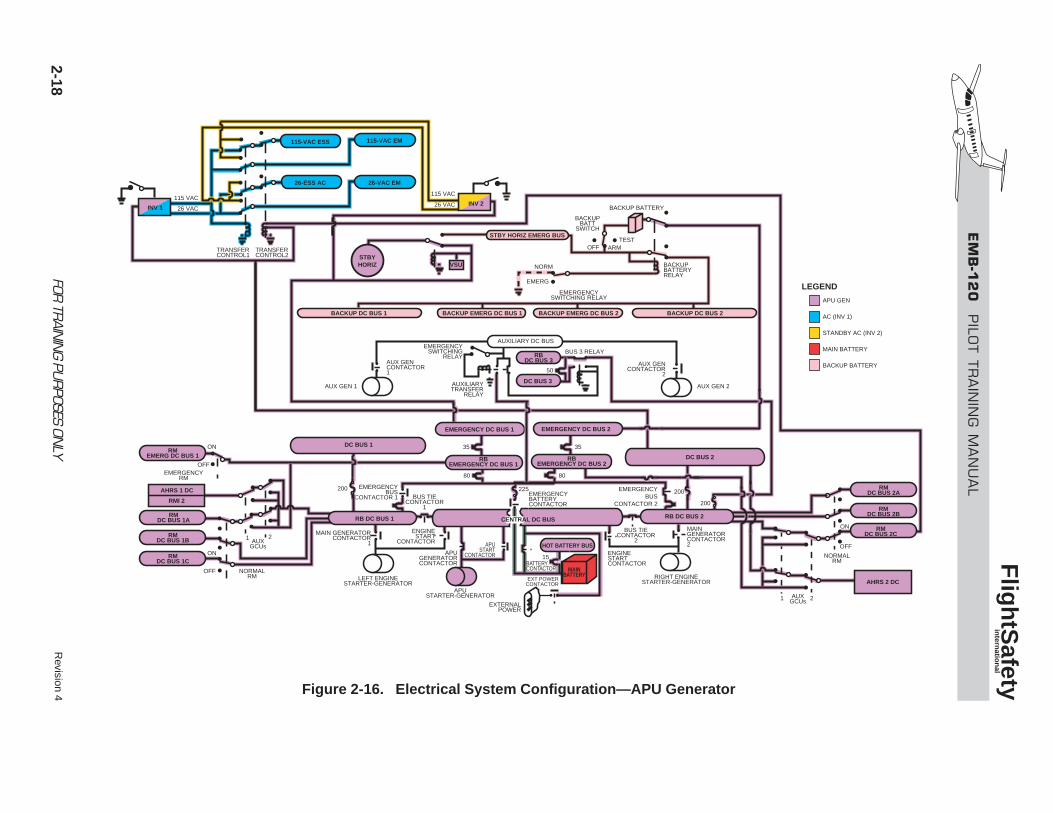
Figure 2-16. Electrical System Configuration—APU Generator
EM
B-1
20
PILO
T T
RA
ININ
G M
AN
UA
L
Flig
htS
afety
intern
ation
al2-19FOR
TRAIN
ING PU
RPOSES ON
LYR
evision 4
115-VAC ESS
26-ESS AC
115-VAC EM
26-VAC EM
VSUSTBYHORIZ
BACKUP DC BUS 1 BACKUP EMERG DC BUS 1 BACKUP EMERG DC BUS 2 BACKUP DC BUS 2
BACKUPBATTERYRELAY
BACKUP BATTERY
BACKUPBATT
SWITCH
OFFTEST
ARM
NORM
115 VAC
26 VAC
115 VAC
26 VAC
TRANSFERCONTROL1
TRANSFERCONTROL2
50
35
80
200 225 200
15
200
80
35
EMERG
EMERGENCYSWITCHING RELAY
AUXILIARY DC BUS
RBDC BUS 3
DC BUS 3AUXILIARYTRANSFER
RELAY
EMERGENCYSWITCHING
RELAYAUX GENCONTACTOR1
AUX GENCONTACTOR
2
AUX GEN 1 AUX GEN 2
BUS 3 RELAY
EMERGENCY DC BUS 2EMERGENCY DC BUS 1
RBEMERGENCY DC BUS 2
RBEMERGENCY DC BUS 1
RIGHT ENGINESTARTER-GENERATOR
MAIN GENERATORCONTACTOR2
ENGINESTARTCONTACTOR
ENGINESTART
CONTACTOR APUSTART
CONTACTOR
EMERGENCYBATTERYCONTACTOR
BATTERYCONTACTOR
HOT BATTERY BUS
MAINBATTERY
RMDC BUS 2A
RMDC BUS 2B
RMDC BUS 2C
ON
OFF
NORMALRM
AHRS 2 DC
1 2AUXGCUsEXTERNAL
POWER
EXT POWERCONTACTOR
CENTRAL DC BUS
BUS TIECONTACTOR
2
BUS TIECONTACTOR
1
APUGENERATORCONTACTOR
APUSTARTER-GENERATOR
LEFT ENGINESTARTER-GENERATOR
MAIN GENERATORCONTACTOR
1
EMERGENCYBUS
CONTACTOR 1
ON
ON
OFF
OFF
EMERGENCYRM
NORMALRM
RMEMERG DC BUS 1
RMDC BUS 1A
RMDC BUS 1B
RMDC BUS 1C
AHRS 1 DC
RMI 2
1 2 AUXGCUs
STBY HORIZ EMERG BUS
DC BUS 2
DC BUS 1
RB DC BUS 1
INV 2INV 1
AC (INV 1)
STANDBY AC (INV 2)
MAIN BATTERY
BACKUP BATTERY
AUXILIARY GENERATOR
R MAIN DC GEN
LEGEND
RB DC BUS 2
EMERGENCYBUS
CONTACTOR 2
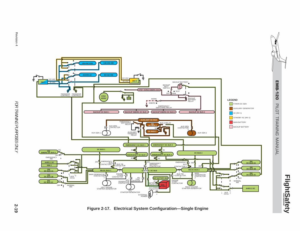
Figure 2-17. Electrical System Configuration—Single Engine
Revision 42-20
Functions of the auxiliary generator GCUs are asfollows:
• At 70% propeller RPM:
• Connects generator to auxiliary DC bus
• Switches relay box DC bus 3 and DC bus3 from relay box DC bus 2 to auxiliaryDC bus
• Voltage regulation same as main generators
• Overvoltage protection (> 32.5 VDC)
• Undervoltage protection (< 23 ±1 VDC)
• Overcurrent protection (220 amps)
• Field excitation protection same as maingenerators
• Paralleling same as main generators
• Underspeed protection when propeller speeddrops below 70%
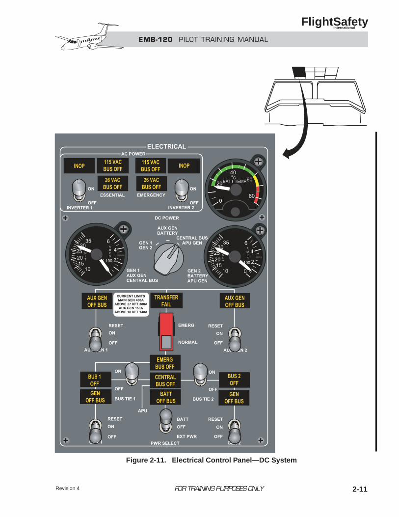
Electrical Control PanelThe DC electrical system is monitored on the over-head electrical control panel (Figure 2-11) by twovoltammeters, the battery temperature gage, and thefollowing annunciator warning lights:
• GEN OFF BUS (left and right main generators)
• BUS 1 OFF
• BUS 2 OFF
• EMERG BUS OFF
• CENTRAL BUS OFF
• BATTERY OFF BUS
• AUX GEN OFF BUS (left and right auxil-iary generators)
• TRANSFER FAIL
A voltammeter selector switch permits monitoringof the volts and amps of each main generator, theauxiliary DC bus, main battery, central bus, and APUgenerator.
AC POWER
COMPONENTS
InvertersThe alternating current system (Figure 2-12) con-sists of two independently powered inverters locat-ed in the nose section of the aircraft and accessiblethrough the electronic compartment door in thenose wheel well. Each inverter produces 115- and26-VAC, 400-Hz power.
Normally both inverters are energized, but only oneis used to power the AC buses. Inverter No. 1, pow-ered from DC bus 2, is the primary AC power source.
Inverter No. 2, powered from emergency DC bus1, is kept in a powered backup status for invert-er No. 1.
Transfer Control RelaysTwo transfer control relays direct the output ofthe inverters to the appropriate AC buses.
Transfer control relay 1 is powered by the 115-VACoutput of inverter No. 1. Transfer control relay 2is powered by DC bus 2 (the power source forinverter No. 1) and radio master DC bus 2C.
FOR TRAINING PURPOSES ONLY
EMB-120 PILOT TRAINING MANUAL
FlightSafety international
EM
B-1
20
PILO
T T
RA
ININ
G M
AN
UA
L
Flig
htS
afety
intern
ation
al2-21FOR
TRAIN
ING PU
RPOSES ON
LYR
evision 4
115-VAC ESS
26-ESS AC
115-VAC EM
26-VAC EM
VSUSTBYHORIZ
BACKUP DC BUS 1 BACKUP EMERG DC BUS 1 BACKUP EMERG DC BUS 2 BACKUP DC BUS 2
BACKUPBATTERYRELAY
BACKUP BATTERY
BACKUPBATT
SWITCH
OFFTEST
ARM
NORM
115 VAC
26 VAC
115 VAC
26 VAC
TRANSFERCONTROL1
TRANSFERCONTROL2
50
35
80
200200
15
200
80
35
EMERG
EMERGENCYSWITCHING RELAY
AUXILIARY DC BUS
RBDC BUS 3
DC BUS 3AUXILIARYTRANSFER
RELAY
EMERGENCYSWITCHING
RELAYAUX GENCONTACTOR1
AUX GENCONTACTOR
2
AUX GEN 1 AUX GEN 2
EMERGENCY DC BUS 2EMERGENCY DC BUS 1
RBEMERGENCY DC BUS 2
RBEMERGENCY DC BUS 1
RIGHT ENGINESTARTER-GENERATOR
MAIN GENERATORCONTACTOR2
ENGINESTARTCONTACTOR
APUSTART
CONTACTOR
EMERGENCYBATTERYCONTACTOR
BATTERYCONTACTOR
HOT BATTERY BUS
MAINBATTERY
RMDC BUS 2A
RMDC BUS 2B
RMDC BUS 2C
ON
OFF
NORMALRM
AHRS 2 DC
1 2AUXGCUsEXTERNAL
POWER
EXT POWERCONTACTOR
CENTRAL DC BUS
APUGENERATORCONTACTOR
APUSTARTER-GENERATOR
LEFT ENGINESTARTER-GENERATOR
ON
ON
OFF
OFF
EMERGENCYRM
NORMALRM
RMEMERG DC BUS 1
RMDC BUS 1A
RMDC BUS 1B
RMDC BUS 1C
AHRS 1 DC
RMI 2
1 2 AUXGCUs
STBY HORIZ EMERG BUS
DC BUS 2
DC BUS 1
RB DC BUS 1
INV 2INV 1
RB DC BUS 2
BUS 3 RELAY
BUS TIECONTACTOR
1
EMERGENCYBUS
CONTACTOR 1
BUS TIECONTACTOR
2
ENGINESTART
CONTACTOR
225
MAIN GENERATORCONTACTOR
1
MAIN BATTERY
BACKUP BATTERY
GCU
EMERGENCY
STANDBY AC (INV 2)
AUXILIARY GENERATORS
LEGEND
EMERGENCYBUS
CONTACTOR 2
Figure 2-18. Emergency Mode—Both Main Generators and One Auxiliary Generator Failure
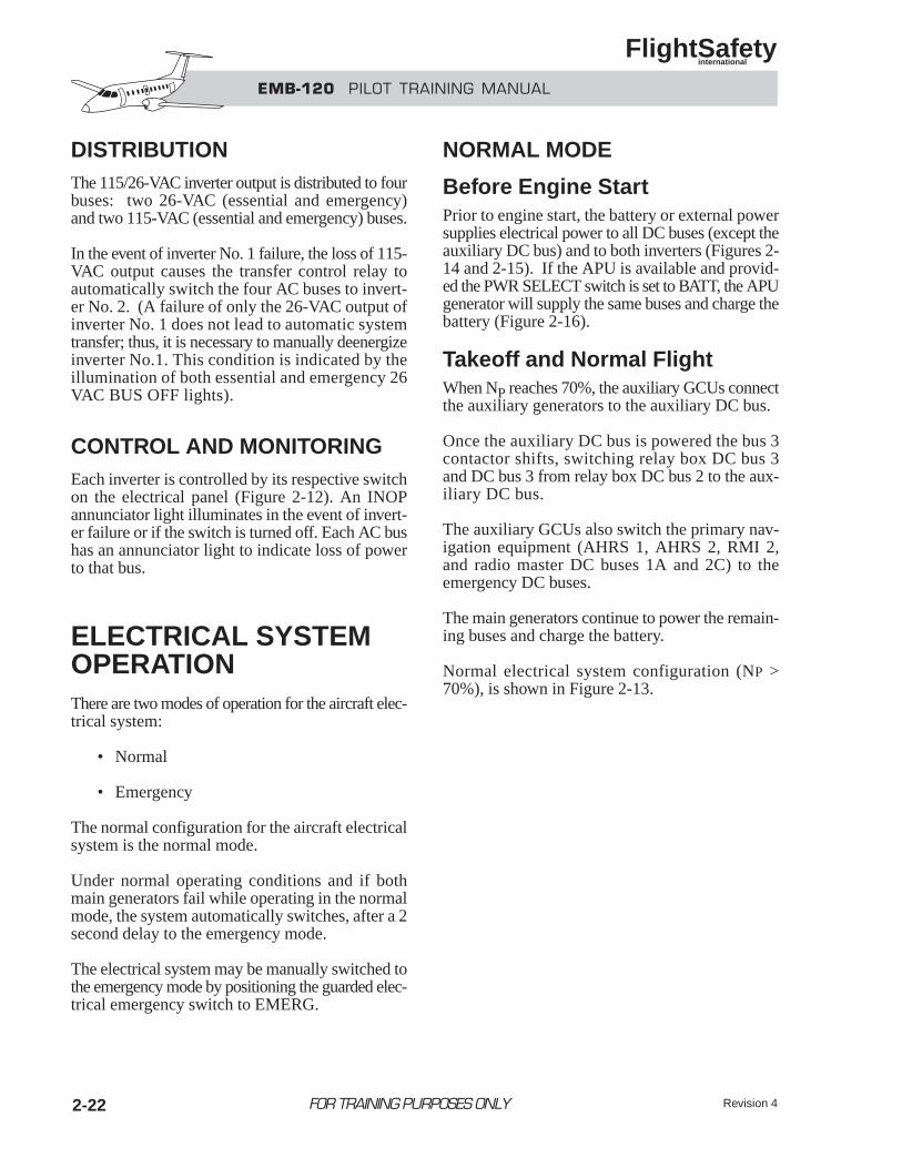
EMB-120 PILOT TRAINING MANUAL
FlightSafety international
DISTRIBUTIONThe 115/26-VAC inverter output is distributed to fourbuses: two 26-VAC (essential and emergency)and two 115-VAC (essential and emergency) buses.
In the event of inverter No. 1 failure, the loss of 115-VAC output causes the transfer control relay toautomatically switch the four AC buses to invert-er No. 2. (A failure of only the 26-VAC output ofinverter No. 1 does not lead to automatic systemtransfer; thus, it is necessary to manually deenergizeinverter No.1. This condition is indicated by theillumination of both essential and emergency 26VAC BUS OFF lights).
CONTROL AND MONITORINGEach inverter is controlled by its respective switchon the electrical panel (Figure 2-12). An INOPannunciator light illuminates in the event of invert-er failure or if the switch is turned off. Each AC bushas an annunciator light to indicate loss of powerto that bus.
ELECTRICAL SYSTEMOPERATIONThere are two modes of operation for the aircraft elec-trical system:
• Normal
• Emergency
The normal configuration for the aircraft electricalsystem is the normal mode.
Under normal operating conditions and if bothmain generators fail while operating in the normalmode, the system automatically switches, after a 2second delay to the emergency mode.
The electrical system may be manually switched tothe emergency mode by positioning the guarded elec-trical emergency switch to EMERG.
NORMAL MODE
Before Engine StartPrior to engine start, the battery or external powersupplies electrical power to all DC buses (except theauxiliary DC bus) and to both inverters (Figures 2-14 and 2-15). If the APU is available and provid-ed the PWR SELECT switch is set to BATT, the APUgenerator will supply the same buses and charge thebattery (Figure 2-16).
Takeoff and Normal FlightWhen NP reaches 70%, the auxiliary GCUs connectthe auxiliary generators to the auxiliary DC bus.
Once the auxiliary DC bus is powered the bus 3contactor shifts, switching relay box DC bus 3and DC bus 3 from relay box DC bus 2 to the aux-iliary DC bus.
The auxiliary GCUs also switch the primary nav-igation equipment (AHRS 1, AHRS 2, RMI 2,and radio master DC buses 1A and 2C) to theemergency DC buses.
The main generators continue to power the remain-ing buses and charge the battery.
Normal electrical system configuration (NP >70%), is shown in Figure 2-13.
2-22 FOR TRAINING PURPOSES ONLY Revision 4
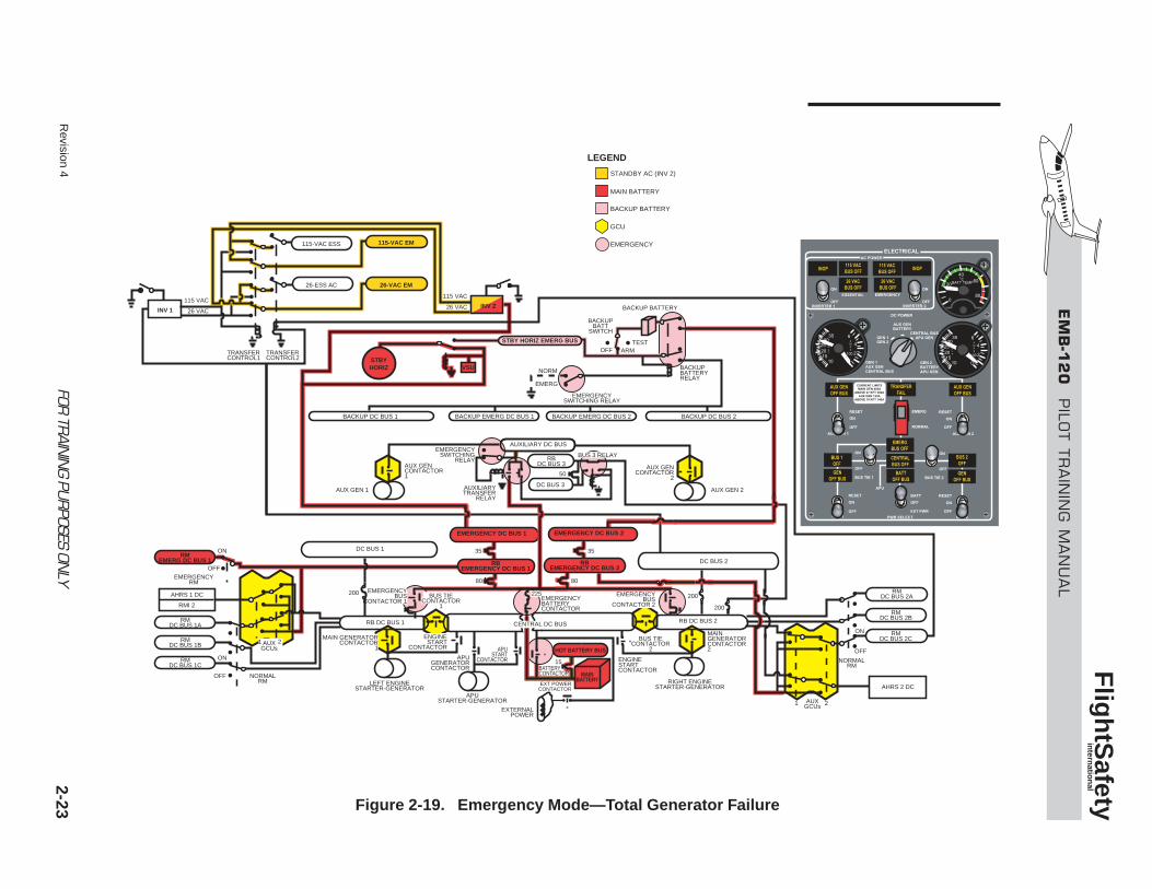
EM
B-1
20
PILO
T T
RA
ININ
G M
AN
UA
L
Flig
htS
afety
intern
ation
al2-23FOR
TRAIN
ING PU
RPOSES ON
LYR
evision 4
115-VAC ESS
26-ESS AC
115-VAC EM
26-VAC EM
VSUSTBYHORIZ
BACKUP DC BUS 1 BACKUP EMERG DC BUS 1 BACKUP EMERG DC BUS 2 BACKUP DC BUS 2
BACKUPBATTERYRELAY
BACKUP BATTERY
BACKUPBATT
SWITCH
OFFTEST
ARM
NORM
115 VAC
26 VAC
115 VAC
26 VAC
TRANSFERCONTROL1
TRANSFERCONTROL2
50
35
80
200 200
15
200
80
35
EMERG
EMERGENCYSWITCHING RELAY
AUXILIARY DC BUS
RBDC BUS 3
DC BUS 3AUXILIARYTRANSFER
RELAY
EMERGENCYSWITCHING
RELAYAUX GENCONTACTOR1
AUX GENCONTACTOR
2
AUX GEN 1 AUX GEN 2
EMERGENCY DC BUS 2EMERGENCY DC BUS 1
RBEMERGENCY DC BUS 2
RBEMERGENCY DC BUS 1
RIGHT ENGINESTARTER-GENERATOR
MAIN GENERATORCONTACTOR2
ENGINESTARTCONTACTOR
APUSTART
CONTACTOR
EMERGENCYBATTERYCONTACTOR
BATTERYCONTACTOR
HOT BATTERY BUS
MAINBATTERY
RMDC BUS 2A
RMDC BUS 2B
RMDC BUS 2C
ON
OFF
NORMALRM
AHRS 2 DC
1 2AUXGCUsEXTERNAL
POWER
EXT POWERCONTACTOR
CENTRAL DC BUS
APUGENERATORCONTACTOR
APUSTARTER-GENERATOR
LEFT ENGINESTARTER-GENERATOR
ON
ON
OFF
OFF
EMERGENCYRM
NORMALRM
RMEMERG DC BUS 1
RMDC BUS 1A
RMDC BUS 1B
RMDC BUS 1C
AHRS 1 DC
RMI 2
STBY HORIZ EMERG BUS
DC BUS 2
DC BUS 1
RB DC BUS 1
INV 2INV 1
RB DC BUS 2
BUS 3 RELAY
BUS TIECONTACTOR
1
EMERGENCYBUS
CONTACTOR 1
BUS TIECONTACTOR
2
ENGINESTART
CONTACTOR
225
MAIN GENERATORCONTACTOR
1
BACKUP BATTERY
GCU
EMERGENCY
MAIN BATTERY
STANDBY AC (INV 2)
LEGEND
AUXGCUs
2 1
EMERGENCYBUS
CONTACTOR 2
Figure 2-19. Emergency Mode—Total Generator Failure
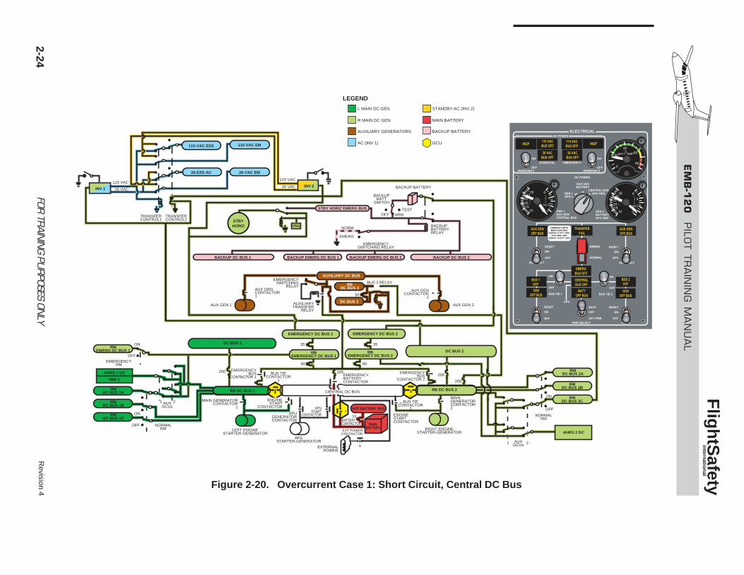
EM
B-1
20
PILO
T T
RA
ININ
G M
AN
UA
L
Flig
htS
afety
intern
ation
al
2-24FOR
TRAIN
ING PU
RPOSES ON
LYR
evision 4
115-VAC ESS
26-ESS AC
115-VAC EM
26-VAC EM
VSUSTBYHORIZ
BACKUP DC BUS 1 BACKUP EMERG DC BUS 1 BACKUP EMERG DC BUS 2 BACKUP DC BUS 2
BACKUPBATTERYRELAY
BACKUP BATTERY
BACKUPBATT
SWITCH
OFFTEST
ARM
NORM
115 VAC
26 VAC
115 VAC
26 VAC
TRANSFERCONTROL1
TRANSFERCONTROL2
50
35
80
200200
15
200
80
35
EMERG
EMERGENCYSWITCHING RELAY
AUXILIARY DC BUS
RBDC BUS 3
DC BUS 3AUXILIARYTRANSFER
RELAY
EMERGENCYSWITCHING
RELAYAUX GENCONTACTOR1
AUX GENCONTACTOR
2
AUX GEN 1 AUX GEN 2
EMERGENCY DC BUS 2EMERGENCY DC BUS 1
RBEMERGENCY DC BUS 2
RBEMERGENCY DC BUS 1
RIGHT ENGINESTARTER-GENERATOR
MAIN GENERATORCONTACTOR2
ENGINESTARTCONTACTOR
APUSTART
CONTACTOR
EMERGENCYBATTERYCONTACTOR
BATTERYCONTACTOR
HOT BATTERY BUS
MAINBATTERY
RMDC BUS 2A
RMDC BUS 2B
RMDC BUS 2C
ON
OFF
NORMALRM
AHRS 2 DC
1 2AUXGCUsEXTERNAL
POWER
EXT POWERCONTACTOR
CENTRAL DC BUS
APUGENERATORCONTACTOR
APUSTARTER-GENERATOR
LEFT ENGINESTARTER-GENERATOR
ON
ON
OFF
OFF
EMERGENCYRM
NORMALRM
RMEMERG DC BUS 1
RMDC BUS 1A
RMDC BUS 1B
RMDC BUS 1C
AHRS 1 DC
RMI 2
STBY HORIZ EMERG BUS
DC BUS 2
DC BUS 1
RB DC BUS 1
INV 2INV 1
RB DC BUS 2
BUS 3 RELAY
BUS TIECONTACTOR
1
EMERGENCYBUS
CONTACTOR 1
BUS TIECONTACTOR
2
ENGINESTART
CONTACTOR
225
MAIN GENERATORCONTACTOR
1
AUXILIARY GENERATORS
AC (INV 1)
R MAIN DC GEN
L MAIN DC GEN
BACKUP BATTERY
GCU
MAIN BATTERY
STANDBY AC (INV 2)
LEGEND
AUXGCUs
2 1
EMERGENCYBUS
CONTACTOR 2
Figure 2-20. Overcurrent Case 1: Short Circuit, Central DC Bus
Revision 4 2-25FOR TRAINING PURPOSES ONLY
EMB-120 PILOT TRAINING MANUAL
FlightSafety international
Single-Engine FlightThe electrical power distribution for single-engineflight (Figure 2-17) is the same as the normal flightconfiguration.
The DC load on the remaining main generatorshould be reduced to 400 amps if the APU gener-ator is not available.
The remaining auxiliary generator continues tosupply the loads of the auxiliary DC bus, relaybox DC bus 3 and DC bus 3 with no restriction.
EMERGENCY MODEThe electrical system may be switched to the emer-gency mode of operation manually; or it mayswitch automatically with the loss of both main gen-erators (after a 2-second delay).
For the switch to occur automatically, the follow-ing conditions must be met:
• At least one main generator switch ON
• PWR SELECT switch in BATT
• Both main generators loss – (Line con-tactors open)
NOTETo prevent a reset to the normal modeafter an automatic switch to the emergen-cy mode, select EMERG on the electricalemergency switch prior to turning both maingenerators switches OFF.
In the emergency mode:
• The emergency bus contactor opens, dis-connecting the emergency DC buses from relaybox DC bus 2.
• The auxiliary transfer relay shifts, connect-ing the emergency DC buses to the auxiliaryDC bus.
• The battery contactor opens, disconnectingthe battery from the central DC bus.
• The emergency battery contactor closes,connecting the battery to the emergency DCbuses.
• The backup battery relay is deenergized,disconnecting the backup buses from thebackup battery.
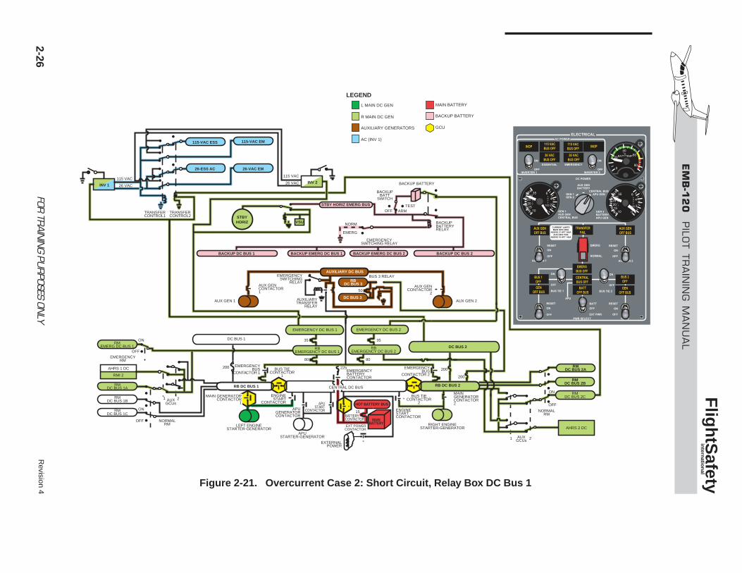
Revision 4
2-26FOR
TRAIN
ING PU
RPOSES ON
LY
EM
B-1
20
PILO
T T
RA
ININ
G M
AN
UA
L
Flig
htS
afety
intern
ation
al
115-VAC ESS
26-ESS AC
115-VAC EM
26-VAC EM
VSUSTBYHORIZ
BACKUP DC BUS 1 BACKUP EMERG DC BUS 1 BACKUP EMERG DC BUS 2 BACKUP DC BUS 2
BACKUPBATTERYRELAY
BACKUP BATTERY
BACKUPBATT
SWITCH
OFFTEST
ARM
NORM
115 VAC
26 VAC
115 VAC
26 VAC
TRANSFERCONTROL1
TRANSFERCONTROL2
50
35
80
200 200
15
200
80
35
EMERG
EMERGENCYSWITCHING RELAY
AUXILIARY DC BUS
RBDC BUS 3
DC BUS 3AUXILIARYTRANSFER
RELAY
EMERGENCYSWITCHING
RELAYAUX GENCONTACTOR1
AUX GENCONTACTOR
2
AUX GEN 1 AUX GEN 2
EMERGENCY DC BUS 2
RBEMERGENCY DC BUS 2
RBEMERGENCY DC BUS 1
RIGHT ENGINESTARTER-GENERATOR
MAIN GENERATORCONTACTOR2
ENGINESTARTCONTACTOR
APUSTART
CONTACTOR
EMERGENCYBATTERYCONTACTOR
EMERGENCYBUS
CONTACTOR 2
BATTERYCONTACTOR
HOT BATTERY BUS
MAINBATTERY
RMDC BUS 2A
RMDC BUS 2B
RMDC BUS 2C
ON
OFF
NORMALRM
AHRS 2 DC
1 2AUXGCUsEXTERNAL
POWER
EXT POWERCONTACTOR
CENTRAL DC BUS
APUGENERATORCONTACTOR
APUSTARTER-GENERATOR
LEFT ENGINESTARTER-GENERATOR
ON
ON
OFF
OFF
EMERGENCYRM
NORMALRM
RMEMERG DC BUS 1
RMDC BUS 1A
RMDC BUS 1B
RMDC BUS 1C
AHRS 1 DC
RMI 2
STBY HORIZ EMERG BUS
DC BUS 2
DC BUS 1
RB DC BUS 1
INV 2INV 1
RB DC BUS 2
BUS 3 RELAY
BUS TIECONTACTOR
1
EMERGENCYBUS
CONTACTOR 1
BUS TIECONTACTOR
2
ENGINESTART
CONTACTOR
225
MAIN GENERATORCONTACTOR
1AUX
GCUs2
EMERGENCY DC BUS 1
AUXILIARY GENERATORS
AC (INV 1)
R MAIN DC GEN
L MAIN DC GEN
BACKUP BATTERY
GCU
MAIN BATTERY
LEGEND
1
Figure 2-21. Overcurrent Case 2: Short Circuit, Relay Box DC Bus 1
Emergency Mode withAPU/Auxiliary GeneratorAvailable
NOTEIf the APU is running, it is connected tothe central DC bus to replace the main gen-erators. The electrical system shouldbe switched to the normal mode to recon-nect the battery and emergency buses tothe central DC bus.
If the APU is not running, the electricalsystem must be switched to the normalmode to energize the central DC bus forAPU airstart.
To switch the electrical system to the normal mode:
• Both main generators switches—OFF
• Electrical emergency switch—NORMAL
Power Source—APU Generator OnlyAfter connecting the APU to the central DC bus andswitching the electrical system to the normal mode,the electrical power distribution is the same asnormal APU only.
Power Source—AuxiliaryGenerator(s) OnlyAll emergency DC buses are powered, the main busesare isolated, and inverter No. 2 powers all ACbuses. Distribution is shown in Figure 2-18.
Power Source—APU Generator andAuxiliary Generator(s)All emergency buses are powered. The main busesfeed from the APU.
Emergency Mode with Loss ofAll Generators Power Source—Battery OnlyThe battery is automatically connected to the emer-gency DC buses and supplies power for approximately30 minutes.
Only the emergency AC buses powered.
Distribution is shown in Figure 2-19.
NOTEThe loads connected to the emergencyDC buses should be reduced at crewdiscretion.
OVERCURRENT PROTECTIONA short circuit in the DC buses could result in anovercurrent condition in the electrical system. Theaircraft is protected from this condition by:
• Automatic intervention of the generator con-trol units (APU, auxiliary, or main GCUs).
• Circuit breakers
• Fuses
The buses protected by GCUs are those that havea direct connection to a generator (i.e., the centralDC bus, relay box DC buses 1 and 2, and the aux-iliary DC bus).
Except for the auxiliary DC bus, a short circuit inany of the other buses protected by GCUs willresult in operational limitations to the aircraft,especially in flight.
The GCUs first priority is to disconnect the battery.
It is strongly recommended not to tryan electrical system reset following ashort circuit in the central DC bus or
CAUTION
Revision 4 2-27FOR TRAINING PURPOSES ONLY
EMB-120 PILOT TRAINING MANUAL
FlightSafety international
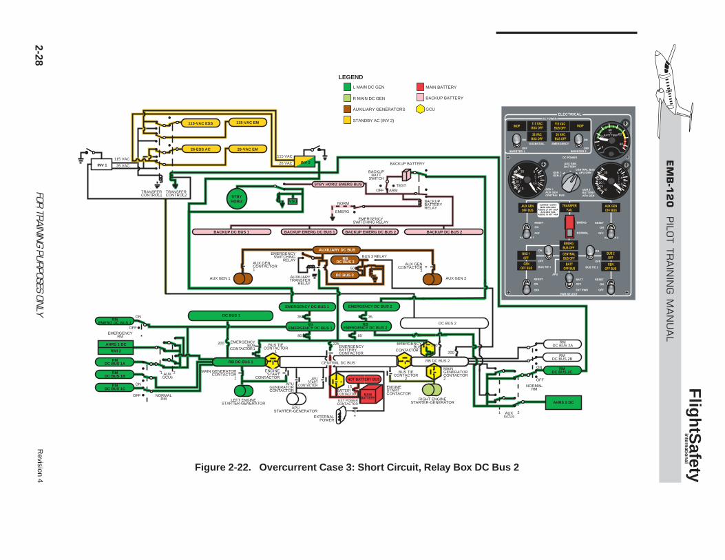
Revision 4
FOR TR
AININ
G PURPOSES ON
LY
EM
B-1
20
PILO
T T
RA
ININ
G M
AN
UA
L
Flig
htS
afety
intern
ation
al
2-28
115-VAC ESS
26-ESS AC
115-VAC EM
26-VAC EM
VSUSTBYHORIZ
BACKUP DC BUS 1 BACKUP EMERG DC BUS 1 BACKUP EMERG DC BUS 2 BACKUP DC BUS 2
BACKUPBATTERYRELAY
BACKUP BATTERY
BACKUPBATT
SWITCH
OFFTEST
ARM
NORM
115 VAC
26 VAC
115 VAC
26 VAC
TRANSFERCONTROL1
TRANSFERCONTROL2
50
35
80
200 200
15
200
80
35
EMERG
EMERGENCYSWITCHING RELAY
AUXILIARY DC BUS
RBDC BUS 3
DC BUS 3AUXILIARYTRANSFER
RELAY
EMERGENCYSWITCHING
RELAYAUX GENCONTACTOR1
AUX GENCONTACTOR
2
AUX GEN 1 AUX GEN 2
EMERGENCY DC BUS 2EMERGENCY DC BUS 1
RBEMERGENCY DC BUS 2
RBEMERGENCY DC BUS 1
RIGHT ENGINESTARTER-GENERATOR
MAIN GENERATORCONTACTOR2
ENGINESTARTCONTACTOR
APUSTART
CONTACTOR
EMERGENCYBATTERYCONTACTOR
BATTERYCONTACTOR
HOT BATTERY BUS
MAINBATTERY
RMDC BUS 2A
RMDC BUS 2B
RMDC BUS 2C
ON
OFF
NORMALRM
AHRS 2 DC
1 2AUXGCUsEXTERNAL
POWER
EXT POWERCONTACTOR
CENTRAL DC BUS
APUGENERATORCONTACTOR
APUSTARTER-GENERATOR
LEFT ENGINESTARTER-GENERATOR
ON
ON
OFF
OFF
EMERGENCYRM
NORMALRM
RMEMERG DC BUS 1
RMDC BUS 1A
RMDC BUS 1B
RMDC BUS 1C
AHRS 1 DC
RMI 2
STBY HORIZ EMERG BUS
DC BUS 2
DC BUS 1
RB DC BUS 1
INV 2INV 1
RB DC BUS 2
BUS 3 RELAY
BUS TIECONTACTOR
1
EMERGENCYBUS
CONTACTOR 1EMERGENCY
BUSCONTACTOR 2
BUS TIECONTACTOR
2
ENGINESTART
CONTACTOR
225
MAIN GENERATORCONTACTOR
1
AUXILIARY GENERATORS
STANDBY AC (INV 2)
R MAIN DC GEN
L MAIN DC GEN
BACKUP BATTERY
GCU
MAIN BATTERY
LEGEND
AUXGCUs
2 1
Figure 2-22. Overcurrent Case 3: Short Circuit, Relay Box DC Bus 2
EMB-120 PILOT TRAINING MANUAL
FlightSafety international
Revision 4 FOR TRAINING PURPOSES ONLY 2-29
relay box DC buses 1 or 2.
NOTEIn the following cases, it is assumed thatthe aircraft is in flight and the electricalsystem was in normal mode prior to theshort circuit.
Case 1—Short Circuit in theCentral DC BusIn the event of a short circuit in the central DC bus(Figure 2-20), both main GCUs isolate the busfrom the electrical system by opening the batterycontactor and bus tie contactors 1 and 2.
If the APU is connected to the central DC bus at thetime the short circuit occurs, it will be disconnect-ed by its GCU.
The following lights illuminate on the electrical panel:
• CENTRAL BUS OFF—Central DC bus is notpowered
• BATT OFF BUS—Battery disconnectedfrom the central DC bus
On APU panel (if connected):
• GEN OFF BUS—APU is not powering thecentral DC bus.
Loss of the central DC bus results in loss of the fol-lowing:
• Engine/APU airstart capability
• Electrical crossfeed (operative main gener-ator supplying the faulty generator buses)
• Battery charging
To regain battery charging, the electrical system mustbe switched to the emergency mode by positioningthe electrical emergency switch to EMERG.
In the emergency mode, the auxiliary DC bus
switches from relay box DC bus 3 and DC bus 3 tothe emergency DC buses and battery.
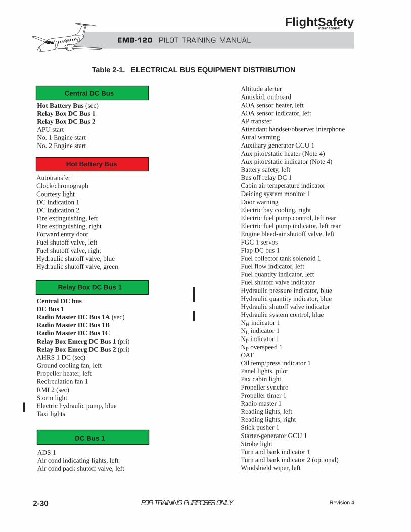
EMB-120 PILOT TRAINING MANUAL
FlightSafety international
Revision 4FOR TRAINING PURPOSES ONLY2-30
Central DC Bus
Hot Battery Bus
Relay Box DC Bus 1
DC Bus 1
Hot Battery Bus (sec)Relay Box DC Bus 1Relay Box DC Bus 2APU startNo. 1 Engine startNo. 2 Engine start
AutotransferClock/chronographCourtesy lightDC indication 1DC indication 2Fire extinguishing, leftFire extinguishing, rightForward entry doorFuel shutoff valve, leftFuel shutoff valve, rightHydraulic shutoff valve, blueHydraulic shutoff valve, green
Central DC busDC Bus 1Radio Master DC Bus 1A (sec)Radio Master DC Bus 1BRadio Master DC Bus 1CRelay Box Emerg DC Bus 1 (pri)Relay Box Emerg DC Bus 2 (pri)AHRS 1 DC (sec)Ground cooling fan, leftPropeller heater, leftRecirculation fan 1RMI 2 (sec)Storm lightElectric hydraulic pump, blueTaxi lights
ADS 1Air cond indicating lights, leftAir cond pack shutoff valve, left
Altitude alerterAntiskid, outboardAOA sensor heater, leftAOA sensor indicator, leftAP transferAttendant handset/observer interphoneAural warningAuxiliary generator GCU 1Aux pitot/static heater (Note 4)Aux pitot/static indicator (Note 4)Battery safety, leftBus off relay DC 1Cabin air temperature indicatorDeicing system monitor 1Door warningElectric bay cooling, rightElectric fuel pump control, left rearElectric fuel pump indicator, left rearEngine bleed-air shutoff valve, leftFGC 1 servosFlap DC bus 1Fuel collector tank solenoid 1Fuel flow indicator, leftFuel quantity indicator, leftFuel shutoff valve indicatorHydraulic pressure indicator, blueHydraulic quantity indicator, blueHydraulic shutoff valve indicatorHydraulic system control, blueNH indicator 1NL indicator 1NP indicator 1NP overspeed 1OATOil temp/press indicator 1Panel lights, pilotPax cabin lightPropeller synchroPropeller timer 1Radio master 1Reading lights, leftReading lights, rightStick pusher 1Starter-generator GCU 1Strobe lightTurn and bank indicator 1Turn and bank indicator 2 (optional)Windshield wiper, left
Table 2-1. ELECTRICAL BUS EQUIPMENT DISTRIBUTION
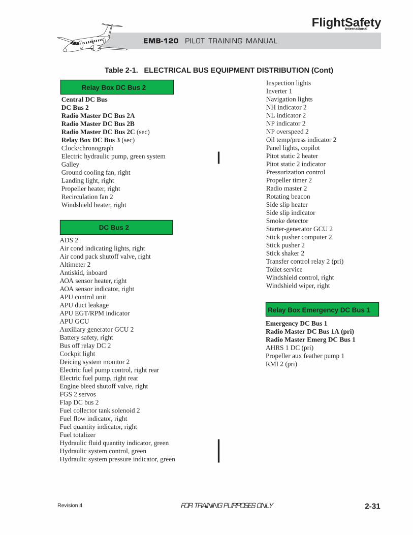
EMB-120 PILOT TRAINING MANUAL
FlightSafety international
Revision 4 FOR TRAINING PURPOSES ONLY 2-31
Relay Box DC Bus 2
DC Bus 2
Relay Box Emergency DC Bus 1
Central DC BusDC Bus 2Radio Master DC Bus 2ARadio Master DC Bus 2BRadio Master DC Bus 2C (sec)Relay Box DC Bus 3 (sec)Clock/chronographElectric hydraulic pump, green systemGalleyGround cooling fan, rightLanding light, rightPropeller heater, rightRecirculation fan 2Windshield heater, right
ADS 2Air cond indicating lights, rightAir cond pack shutoff valve, rightAltimeter 2Antiskid, inboardAOA sensor heater, rightAOA sensor indicator, rightAPU control unitAPU duct leakageAPU EGT/RPM indicatorAPU GCUAuxiliary generator GCU 2Battery safety, rightBus off relay DC 2Cockpit lightDeicing system monitor 2Electric fuel pump control, right rearElectric fuel pump, right rearEngine bleed shutoff valve, rightFGS 2 servosFlap DC bus 2Fuel collector tank solenoid 2Fuel flow indicator, rightFuel quantity indicator, rightFuel totalizerHydraulic fluid quantity indicator, greenHydraulic system control, greenHydraulic system pressure indicator, green
Inspection lightsInverter 1Navigation lightsNH indicator 2NL indicator 2NP indicator 2NP overspeed 2Oil temp/press indicator 2Panel lights, copilotPitot static 2 heaterPitot static 2 indicatorPressurization controlPropeller timer 2Radio master 2Rotating beaconSide slip heaterSide slip indicatorSmoke detectorStarter-generator GCU 2Stick pusher computer 2Stick pusher 2Stick shaker 2Transfer control relay 2 (pri)Toilet serviceWindshield control, rightWindshield wiper, right
Emergency DC Bus 1Radio Master DC Bus 1A (pri)Radio Master Emerg DC Bus 1AHRS 1 DC (pri)Propeller aux feather pump 1RMI 2 (pri)
Table 2-1. ELECTRICAL BUS EQUIPMENT DISTRIBUTION (Cont)
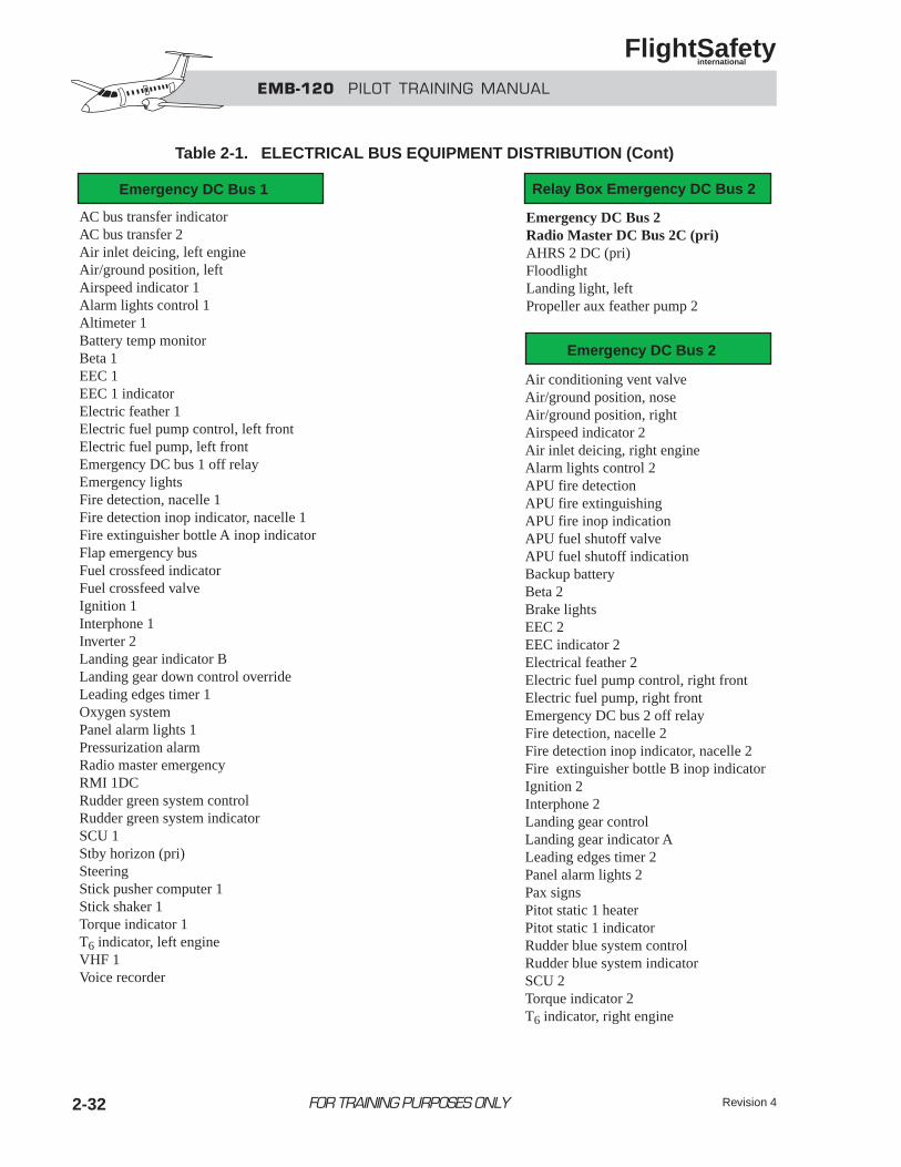
EMB-120 PILOT TRAINING MANUAL
FlightSafety international
Revision 42-32 FOR TRAINING PURPOSES ONLY
Emergency DC Bus 1 Relay Box Emergency DC Bus 2
Emergency DC Bus 2
AC bus transfer indicatorAC bus transfer 2Air inlet deicing, left engineAir/ground position, leftAirspeed indicator 1Alarm lights control 1Altimeter 1Battery temp monitorBeta 1EEC 1EEC 1 indicatorElectric feather 1Electric fuel pump control, left frontElectric fuel pump, left frontEmergency DC bus 1 off relayEmergency lightsFire detection, nacelle 1Fire detection inop indicator, nacelle 1Fire extinguisher bottle A inop indicatorFlap emergency busFuel crossfeed indicatorFuel crossfeed valveIgnition 1Interphone 1Inverter 2Landing gear indicator BLanding gear down control overrideLeading edges timer 1Oxygen systemPanel alarm lights 1Pressurization alarmRadio master emergencyRMI 1DCRudder green system controlRudder green system indicatorSCU 1Stby horizon (pri)SteeringStick pusher computer 1Stick shaker 1Torque indicator 1T6 indicator, left engineVHF 1Voice recorder
Emergency DC Bus 2Radio Master DC Bus 2C (pri)AHRS 2 DC (pri)FloodlightLanding light, leftPropeller aux feather pump 2
Air conditioning vent valveAir/ground position, noseAir/ground position, rightAirspeed indicator 2Air inlet deicing, right engineAlarm lights control 2APU fire detectionAPU fire extinguishingAPU fire inop indicationAPU fuel shutoff valveAPU fuel shutoff indicationBackup batteryBeta 2Brake lightsEEC 2EEC indicator 2Electrical feather 2Electric fuel pump control, right frontElectric fuel pump, right frontEmergency DC bus 2 off relayFire detection, nacelle 2Fire detection inop indicator, nacelle 2Fire extinguisher bottle B inop indicatorIgnition 2Interphone 2Landing gear controlLanding gear indicator ALeading edges timer 2Panel alarm lights 2Pax signsPitot static 1 heaterPitot static 1 indicatorRudder blue system controlRudder blue system indicatorSCU 2Torque indicator 2T6 indicator, right engine
Table 2-1. ELECTRICAL BUS EQUIPMENT DISTRIBUTION (Cont)
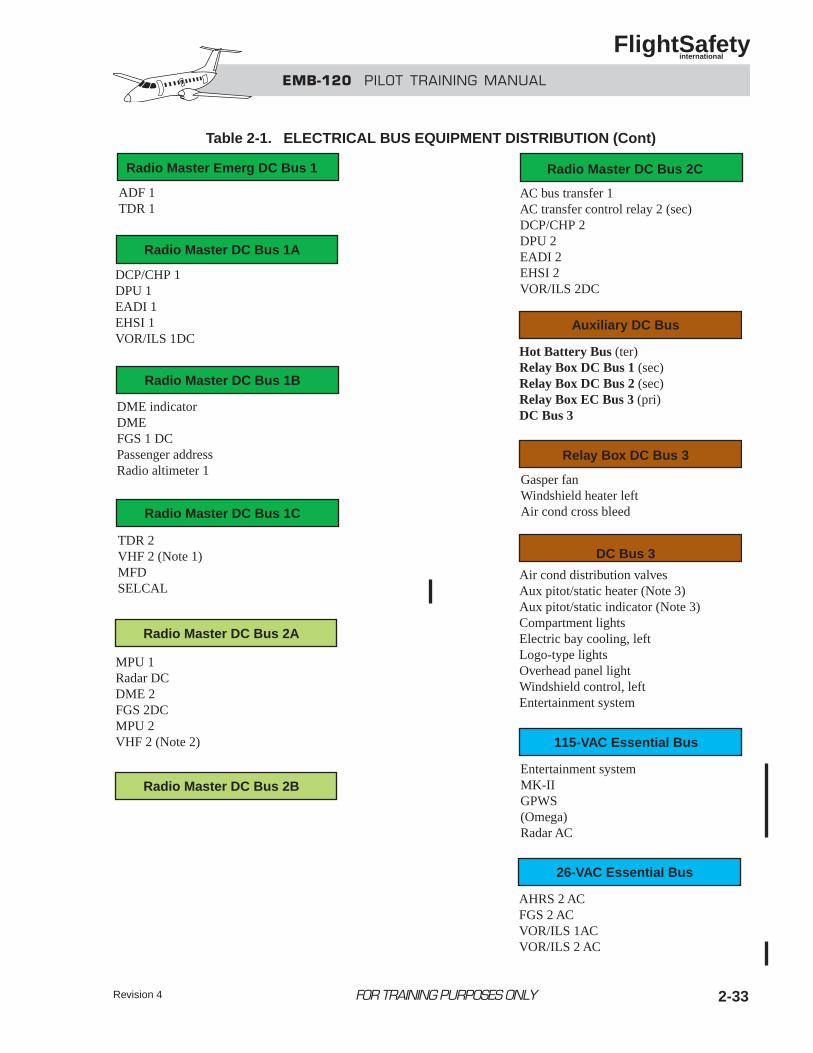
Revision 4 2-33FOR TRAINING PURPOSES ONLY
EMB-120 PILOT TRAINING MANUAL
FlightSafety international
Radio Master Emerg DC Bus 1
Radio Master DC Bus 1A
Radio Master DC Bus 2C
ADF 1TDR 1
DCP/CHP 1DPU 1EADI 1EHSI 1VOR/ILS 1DC
AC bus transfer 1AC transfer control relay 2 (sec)DCP/CHP 2DPU 2EADI 2EHSI 2VOR/ILS 2DC
Radio Master DC Bus 1B
DME indicatorDMEFGS 1 DCPassenger addressRadio altimeter 1
Radio Master DC Bus 1C
TDR 2VHF 2 (Note 1)MFDSELCAL
Radio Master DC Bus 2A
MPU 1Radar DCDME 2FGS 2DCMPU 2VHF 2 (Note 2)
Radio Master DC Bus 2B
Auxiliary DC Bus
Hot Battery Bus (ter)Relay Box DC Bus 1 (sec)Relay Box DC Bus 2 (sec)Relay Box EC Bus 3 (pri)DC Bus 3
Relay Box DC Bus 3
Gasper fanWindshield heater leftAir cond cross bleed
DC Bus 3
Air cond distribution valvesAux pitot/static heater (Note 3)Aux pitot/static indicator (Note 3)Compartment lightsElectric bay cooling, leftLogo-type lightsOverhead panel lightWindshield control, leftEntertainment system
115-VAC Essential Bus
Entertainment systemMK-IIGPWS(Omega)Radar AC
26-VAC Essential Bus
AHRS 2 ACFGS 2 ACVOR/ILS 1ACVOR/ILS 2 AC
Table 2-1. ELECTRICAL BUS EQUIPMENT DISTRIBUTION (Cont)
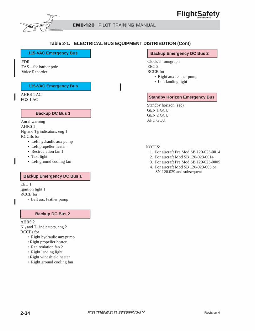
Revision 42-34 FOR TRAINING PURPOSES ONLY
EMB-120 PILOT TRAINING MANUAL
FlightSafety international
FDRTAS—for barber poleVoice Recorder
AHRS 1 ACFGS 1 AC
Backup DC Bus 1
Aural warningAHRS 1NH and T6 indicators, eng 1RCCBs for • Left hydraulic aux pump • Left propeller heater • Recirculation fan 1 • Taxi light • Left ground cooling fan
115-VAC Emergency Bus
115-VAC Emergency Bus
Backup Emergency DC Bus 1
EEC 1Ignition light 1RCCB for: • Left aux feather pump
Backup DC Bus 2
AHRS 2NH and T6 indicators, eng 2RCCBs for • Right hydraulic aux pump • Right propeller heater • Recirculation fan 2 • Right landing light • Right windshield heater • Right ground cooling fan
Backup Emergency DC Bus 2
Clock/chronographEEC 2RCCB for: • Right aux feather pump • Left landing light
Standby Horizon Emergency Bus
Standby horizon (sec)GEN 1 GCUGEN 2 GCUAPU GCU
NOTES: 1. For aircraft Pre Mod SB 120-023-0014 2. For aircraft Mod SB 120-023-0014 3. For aircraft Pre Mod SB 120-023-0005 4. For aircraft Mod SB 120-023-005 or
SN 120.029 and subsequent
Table 2-1. ELECTRICAL BUS EQUIPMENT DISTRIBUTION (Cont)
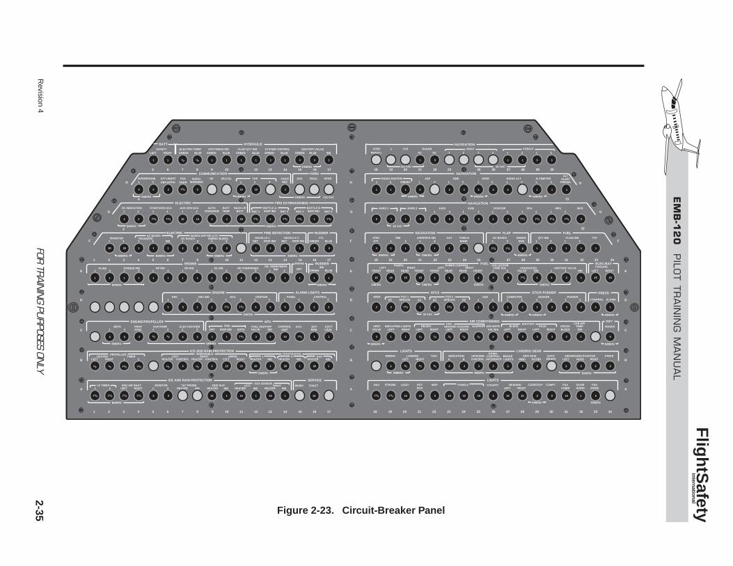
Revision 4
2-35FOR
TRAIN
ING PU
RPOSES ON
LY
EM
B-1
20
PILO
T T
RA
ININ
G M
AN
UA
L
Flig
htS
afety
intern
ation
al
BATT HYDRAULIC
SAFETY ELECTRIC PUMP HYD PRESS IND FLUID QTY IND SYSTEM CONTROL SHUTOFF VALVELEFT GREEN BLUE GREEN BLUE GREEN BLUE GREEN BLUE GREEN BLUE IND
RADAR RNAVTASXFER ΩΩ AC 1 12 1 2 1 22RNAV/ DCRIGHT
COMMUNICATION NAVIGATION
NAVIGATION
FDRS
INTERPHONE ATT HNDST PAX HF SELCAL VHF ADS ADF
EMERG
FDAU DFDRAURALWARNING
VOICEREC1
1 1 1 1 1 1 1 1 1 1
1 1 1 1 1 12 2 2 23
3 1 1 1 1
1 1 1 1 1 13
3 3 3 3 3 3 2 1 51 1
3 3 3
1 1 1 1 1 1 1
3
1 1 3 35
5 1 1 1 15 5 5 5 5 5
3 31/2
1/2
1/2
2 2
2 2 10 10 20
20 20 1 1 1 1 1 1 12 2
2 111111
5
5 5 5
3 3 1 1 115 15 20 20 20
52 1 1 1 1 1103
5 5 5 5 51 1 2 2
11111 1 1 1 12
2 2 2 2
2 1 1 1
2 2 110 107
1/2
1/2
1/2 1/2 1/2 1/2
1/2
7
1/27
1/27
1/27 1/27 1/27 1/27 1/27
2
2 2 21 1 1 1 1 1 13 3 3 3 3
2 2 3 2 2 2 2 2 2 2 2
1/2
1/2
1/2 1/2 1/2 1/2 1/2
1/2 1/2
7
1/27
5 2 2 5 1 53 3 1 1 115 15 15 15 15 10 10
15 15 15 15 15 15
10 10 10 15 15
1/27
1/27
1/27 1/27 1/27 1/27
1/27 1/27 1/27 1/27 1/27
1/27 1/27 5
1/27 1/27 1/271/27
2
65
2 3 4 5 6 7 8 10 11 12 13 14 15 16 17 18 19 20 21 22 23 24 25 27 28 29 30 31 32 33 34 1
2 3 4 5 6 7 8 109 11 12 13 14 15 16 171 19 20 21 22 23 24 25 2726 28 29 30 31 32 33 3418
4
3
H
G
F
H H
G G
F F
E
D
C
B
A
E
D
C
B
E
D
C
B
AA
7 8 9 10 12 13 14 15 16 17 18 19 20 21 22 23 25 26 27 28 29 30
31
32
1 2 3ADDROBS INTPHRADIO MASTER
1 2 1 2DME
1 2XPDR
ALTALERT
PRESEL1 2RADIO ALT1 2
ALTIMETER1 2EMERG
NAVIGATION
EADIAHRS 11 2
EHSI1 2
DPU1 2
MPU MFD1 2
DCP/CHP1 2
AHRS 2
ELECTRIC FIRE EXTINGUISHING
DC INDICATION
EMERG
1 2
1 2
1 2
1 2
START/GEN GCU1 2
AUX GEN GCU AUTOTRANSFER
BATTTEMP
BACK UPBATT
BOTTLE AINOP IND1 NAC 1 NAC 2 NAC 1 NAC 22
ELECTRIC FIRE DETECTION RUDDER NAVIGATION FLAP FUEL
INVERTERAC BUSES
TRANSFERIND 1 2
BUSES OFF RELAYSDC BUSES
1 2EMERG BUSES
DET INOP INDNACELLE 1
DET INOP INDNACELLE 2
GREEN BLUECTL
1 2RMI
1 2DC BUSESOAT TOT
1 2AIRSPEED IND
1 2QTY IND
1 2FLOW IND
ATTSTBY
BANKTURN &
BUSEMERG
RUDDER
GREEN BLUEIND
LEFT RIGHT
COOLING
FRONT FRONTREAR REARLEFT RIGHT
PUMPS
FRONT FRONTREAR REARLEFT RIGHT
21 21TANK SOL
IND INDVALVECROSSFEED SHUTOFF VALVE
PUMPS CONTROL COLLECTOR
LEFT RIGHT
ICE AND RAIN PROTECTIONPROPELLER
HEATERHEATER CONTROL
LEFTHEATER CONTROL
RIGHTLEFT RIGHT
WIPER1 2
TIMER
HEATER IND
ICE AND RAIN PROTECTION SERVICE LIGHTS AOA SENSOR
LEFT NAV STROBE LOGO ROTBCN LEFT RIGHT CABIN
INSP READING COURTESY COMPT PAXSIGNSPAX
WARNDOORPANELS COCKPIT
HEATER INDSIDE SLIP
HEATER INDTAT PROBE
LEFT RIGHTENG AIR INLET
1 2LE TIMER
1 2MONITOR
HEATER INDRIGHT MUSIC TOILET
WINDSHIELD
HEATER IND1
PITOT/STATIC
HEATER IND2
LANDING GEARLIGHTS
A BINDICATIONEMERG TAXILANDING
INBD OUTBD NOSELEFTLEFT RIGHTRIGHTANTI-SKID
CONTROL OVERRIDERUP/DOWN CONTROL
LIGHTSBRAKE
BRAKEAUTO STEERAIR/GROUND POSITION
DOWN
HEATER INDAUX
ENGINET6 IND
1 2 1 2TORQUE IND
1 2NP IND
1 2NH IND
1 2NL IND
1 2NP OVERSPEED
ENGINE/PROPELLER
1 2AUX PUMP
1 2 DET EXTGELEC FEATHER
VALVE INDFUEL SHUTOFF
1 2BETA GCU EGT
RPM DUCTLEAK
PROPSYNC
CONTROLUNIT
FIREINOP IND
APU
ENGINE ALARM LIGHTS
1 2EEC
1 2EEC IND
1 2SCU
1 2IGNITION
1 2PANEL
1 2CONTROL
AFCS STICK PUSHER
1 2PUSHER
1 2SHAKER
1 2COMPUTER
1 2ADSXFER
AC DCSERVOSFGS 2
DC ACSERVOSFGS 1
OIL TEMP/PRESSIND
SMOKE FUEL ELEC-BAY
DET
BOTTLE BINOP IND
VOR/ILS
EMERG
EMERG
EMERG
EMERG
EMERGEMERG EMERG EMERG
EMERG
EMERG EMERG
EMERG
26 VAC
26 VAC
EMERG
EMERG EMERG
EMERGEMERGEMERG
EMERGEMERG 115 VAC
115 VAC 26 VAC
EMERG
EMERG
EMERG
EMERG
EMERG EMERG
EMERG
EMERG
EMERG
EMERG EMERG
EMERG
EMERG
EMERG
CONTROL ALARM
PRESS
VALVESVALVEGROUND COOLINGVENT RECIRC GASPER BLEEDAIR DISTR
LEFT RIGHT LEFT RIGHT LEFT RIGHT LEFT RIGHTPACK CROSS TEMP
LEFT RIGHT BLEED IND INDICATING LIGHTS MASKS
FAN SHUTOFF CAB AIRAIR CONDITIONING OXY
EMERG
Figure 2-23. Circuit-Breaker Panel
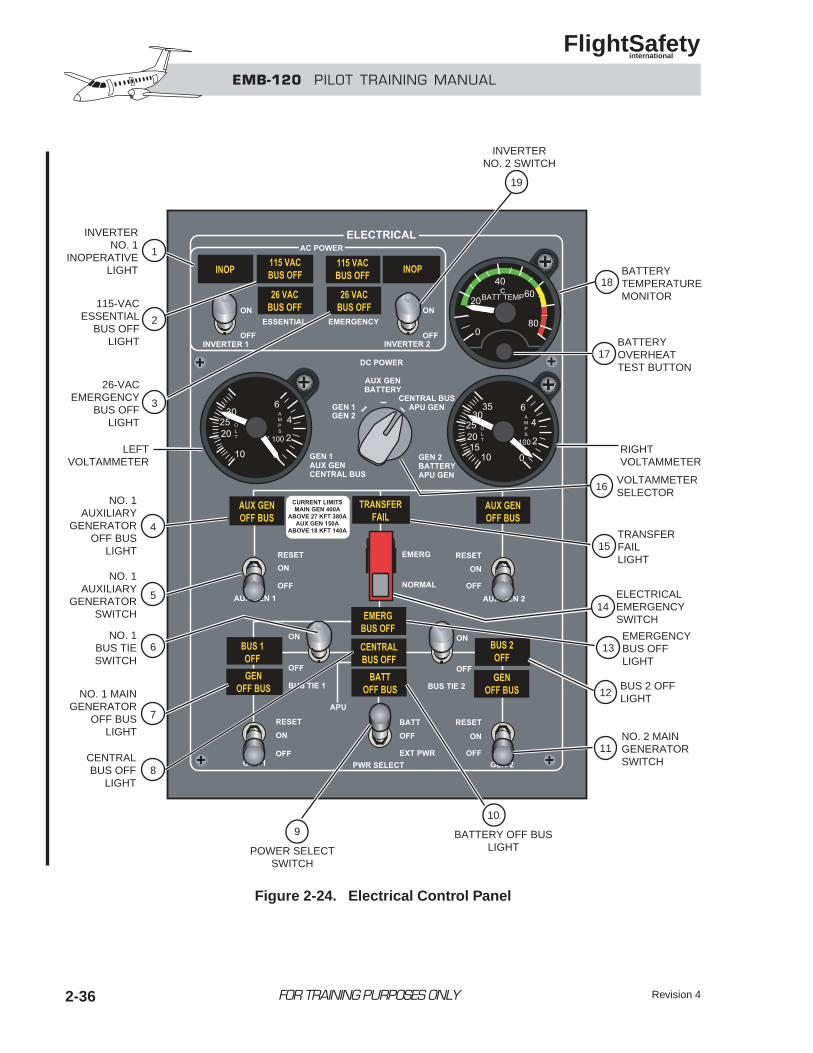
2-36 FOR TRAINING PURPOSES ONLY
EMB-120 PILOT TRAINING MANUAL
FlightSafety international
Revision 4
EMERGENCYBUS OFFLIGHT
ELECTRICALEMERGENCYSWITCH
VOLTAMMETERSELECTOR
RIGHTVOLTAMMETER
LEFTVOLTAMMETER
BUS 2 OFFLIGHT
TRANSFERFAILLIGHT
INVERTERNO. 2 SWITCH
19
18
13
15
12
11
10
BATTERY OFF BUSLIGHT
9
POWER SELECTSWITCH
BATTERYTEMPERATUREMONITOR
NO. 2 MAINGENERATORSWITCH
14
16
17BATTERYOVERHEATTEST BUTTON
INVERTERNO. 1
INOPERATIVELIGHT
1
2
3
4
7
8
5
6
115-VACESSENTIAL
BUS OFFLIGHT
26-VACEMERGENCY
BUS OFFLIGHT
NO. 1AUXILIARY
GENERATOROFF BUS
LIGHT
NO. 1 MAINGENERATOR
OFF BUSLIGHT
CENTRALBUS OFF
LIGHT
NO. 1AUXILIARY
GENERATORSWITCH
NO. 1BUS TIESWITCH
Figure 2-24. Electrical Control Panel
The electrical distribution is as follows:
• Generator 1 continues to power relay box DCbus 1 and DC bus 1.
• Generator 2 continues to power relay boxDC bus 2 and DC bus 2, and picks uprelay box DC bus 3 and DC bus 3 viarelay box DC bus 2.
• Through the auxiliary DC bus, the auxil-iary generators power all emergency DCbuses and charge the battery.
• The central DC bus remains isolated from theelectrical system.
The flight may be continued at the pilot’s discretion;however, engine/APU airstart and electrical cross-feed are not available.
NOTEThe CENTRAL BUS OFF and the BAT-TERY OFF BUS lights remain on.
Case 2—Short Circuit in RelayBox DC Bus 1In the event of a short circuit in relay box DC bus1 (Figure 2-21), the main GCUs isolate both relaybox DC bus 1 and the central DC bus from the elec-trical system by opening the main generator con-tactor 1, the battery contactor, and bus tie contactors1 and 2.
The following lights illuminate on the electrical panel:
• GEN 1 OFF BUS—Main generator 1 is iso-lated from the system.
• BUS 1 OFF—DC bus 1 is not powered.
• CENTRAL BUS OFF—Central DC bus is notpowered.
• BATTERY OFF BUS—Battery is discon-nected from the central DC bus.
NOTEIn some cases, the CENTRAL BUS OFFlight will not illuminate.
Loss of the central DC bus results in loss of thefollowing:
• Engine/APU airstart capability
• Electrical crossfeed
• Battery charging
Loss of relay box DC bus 1 results in loss of thefollowing:
• All equipment connected to:
• DC Bus 1
• Radio master DC buses 1B and 1C.
The aircraft is limited to 25,000 ft, since the left enginebleed (DC bus 1) is closed.
To regain the emergency buses and battery charging,the electrical system must be switched to emergen-cy mode by positioning the electrical emergency switchto EMERG. In the emergency mode, the auxiliary DCbus switches from relay box DC bus 3 and DC bus3 to the emergency DC buses and battery.
Revision 4 2-37FOR TRAINING PURPOSES ONLY
EMB-120 PILOT TRAINING MANUAL
FlightSafety international
The electrical distribution is as follows:
• The main generator 2 continues to supply relaybox DC bus 2 and DC bus 2, and picks up relaybox DC bus 3 and DC bus 3.
• The auxiliary generators, through the auxil-iary DC bus, power all emergency DC busesand charge the battery.
• The following buses remain deenergized:
• Central DC bus
• Relay box DC bus 1
• DC bus 1
• Radio master DC bus 1B and 1C
The left engine bleed is still closed (DC bus 1) lim-iting the aircraft to 25,000 ft.
The flight may be continued at the pilot’s discretion;however, engine/APU airstart and electrical cross-feed are not available, and equipment connected tothe lost buses is also out. Therefore, it is recommendedto land as soon as practical.
NOTEThe GEN 1 GEN OFF BUS, BUS 1OFF, CENTRAL BUS OFF, and BATT-ERY OFF BUS lights remain on.
Case 3—Short Circuit in RelayBox DC Bus 2In the event of a short circuit in relay box DC bus2 (Figure 2-22), the main GCUs isolate both relaybox DC bus 2 and the central DC bus from the elec-trical system by opening the main generator con-tactor 2, the battery contactor, and bus tie contactors1 and 2, and emergency bus contactor 2.
The following lights illuminate on the electrical panel:
• (GEN 2) GEN OFF BUS—Main generator2 is isolated from the system.
• BUS 2 OFF—DC bus 2 is not powered.
• CENTRAL BUS OFF—Central DC bus is notpowered.
• BATTERY OFF BUS—Battery is discon-nected from the central DC bus.
• (INVERTER 1) INOP—Inverter 1 is notpowered.
NOTEIn some cases, the CENTRAL BUS OFFlight will not illuminate.
Loss of the central DC bus results in loss of thefollowing:
• Engine/APU airstart capability
• Electrical crossfeed
• Battery charging
Loss of relay box DC bus 2 results in loss of all equip-ment connected to:
• DC bus 2
• Radio master DC bus 2A and 2B
The right engine bleed (DC Bus 2) is closed, lim-iting airplane to 25,000 ft.
Emergency bus contactor 2 opens and emergencybus contactor 1 closes precluding the loss of emer-gency busses.
To regain battery charging, the electrical system mustbe switched to the emergency mode by positioningthe electrical emergency switch to EMERG. In theemergency mode, the auxiliary DC bus switches fromrelay box DC bus 3 and DC bus 3 to the emergen-cy buses and battery.
NOTEDue to the loss of DC bus 2, this proce-dure results in the loss of relay box DCbus 3 and DC bus 3.
Revision 42-38 FOR TRAINING PURPOSES ONLY
EMB-120 PILOT TRAINING MANUAL
FlightSafety international
The electrical distribution is as follows:
• The main generator 1 continues to power relaybox DC bus 1 and DC bus 1.
• Through the auxiliary DC bus, the auxil-iary generators power all emergency DCbuses and charge the battery.
• The following buses remain deenergized:
• Central DC bus
• Relay box DC bus 2
• DC bus 2
• Relay box DC bus 3
• DC bus 3
• Radio master DC bus 2A and 2B
The flight may be continued at the pilot’s discretion;however, engine/APU airstart and electrical cross-feed are not available, and equipment connected tothe lost buses is also out. Therefore, it is recommendedto land as soon as practical.
NOTEThe GEN 2 GEN OFF BUS, BUS 2OFF, CENTRAL BUS OFF, BATTERYOFF BUS, and inverter 1 INOP lightsremain on.
Case 4—Short Circuit in theCentral DC Bus, Relay Box DCBus 1, or Relay Box DC Bus 2on the GroundA short circuit with the airplane on the ground resultsin the same GCU logic of operation as in flight. Onthe ground, however, the auxiliary DC bus is normallydeenergized and relay box DC bus 3 and DC bus 3 arenormally powered by relay box DC bus 2.
Revision 4 2-39FOR TRAINING PURPOSES ONLY
EMB-120 PILOT TRAINING MANUAL
FlightSafety international
QUESTIONS
PRE MOD SB 120-024-0051 ELECTRICALSYSTEM DIFFERENCESThis manual does not cover Pre Mod electrical dif-ferences. Refer to appropriate Embraer AFM and OPSmanuals.
ELECTRICAL CONTROLPANEL SUMMARY
1. Inverter 1 INOP Light—Illuminates whenInverter No. 1 is not operating due to invert-er failure, loss of power, or switch in the OFFposition.
2. Essential 115 VAC BUS OFF Light—Illu-minates when the 115-VAC essential bus isdeenergized.
3. EMERGENCY 26 VAC BUS OFF Light—Illuminates when the 26-VAC emergencyBus is deenergized.
4. No. 1 AUX GEN OFF BUS Light—Illu-minates when the auxiliary generator contactorNo. 1 is open, isolating the generator from theelectrical system.
5. AUX GEN 1 Switch—
• OFF: Disconnects auxiliary generator No.1 from the auxiliary DC bus.
• ON: Connects the No. 1 auxiliary gener-ator to auxiliary DC bus.
• RESET: This momentary position recon-nects the No. 1 auxiliary generator.
6. BUS TIE 1 Switch—
• Off: Disconnects relay box DC bus 1from the central DC bus.
• ON: Connects relay box DC bus 1 to thecentral DC bus.
7. No. 1 GEN OFF BUS Light—Illuminateswhen the main generator contactor No. 1 isopen, isolating the generator from the elec-trical system.
8. CENTRAL BUS OFF Light—Illuminateswhen the central DC bus is not powered.
Revision 42-40 FOR TRAINING PURPOSES ONLY
EMB-120 PILOT TRAINING MANUAL
FlightSafety international
3-i
CHAPTER 3LIGHTING
CONTENTS
Page
INTRODUCTION .................................................................................................................... 3-1
GENERAL................................................................................................................................ 3-1
INTERNAL LIGHTING .......................................................................................................... 3-2
Cockpit Lighting ............................................................................................................... 3-2
Passenger Cabin Lighting.................................................................................................. 3-5
Compartment Lighting ...................................................................................................... 3-7
EXTERNAL LIGHTING ......................................................................................................... 3-8
Landing Lights .................................................................................................................. 3-8
Taxi Lights......................................................................................................................... 3-9
Navigation Lights.............................................................................................................. 3-9
Rotating Beacons .............................................................................................................. 3-9
Strobe Lights ..................................................................................................................... 3-9
Wing Inspection Lights ..................................................................................................... 3-9
Logo Lights ....................................................................................................................... 3-9
EMERGENCY LIGHTING ................................................................................................... 3-10
Internal Emergency Lights.............................................................................................. 3-10
External Emergency Lights............................................................................................. 3-10
Operation ........................................................................................................................ 3-11
QUESTIONS.......................................................................................................................... 3-12
FOR TRAINING PURPOSES ONLY
EMB-120 PILOT TRAINING MANUAL
FlightSafety international
3-iii
ILLUSTRATIONS
Figure Title Page
3-1 Cockpit Lighting Controls .........................................................................................3-2
3-2 Fluorescent, Utility, and Dome Lighting ....................................................................3-3
3-3 Observer Lights .........................................................................................................3-4
3-4 Passenger Cabin Lighting...........................................................................................3-5
3-5 Passenger Advisory Lights .........................................................................................3-6
3-6 Flight Attendant Call Lights .......................................................................................3-6
3-7 Sterile Light ................................................................................................................3-7
3-8 External Lights ...........................................................................................................3-8
3-9 External Lights Control Panel ....................................................................................3-8
3-10 Emergency Illuminated Areas ..................................................................................3-10
3-11 Cockpit Emergency Lighting Switch .......................................................................3-11
3-12 Flight Attendant Emergency Lighting Switch..........................................................3-11
FOR TRAINING PURPOSES ONLY
EMB-120 PILOT TRAINING MANUAL
FlightSafety international
EMB-120 PILOT TRAINING MANUAL
FlightSafety international
3-1
INTRODUCTIONLighting on the EMB-120 includes lighting for both the interior and exterior of the aircraft. Inter-nal lighting consists of cockpit area and instrument lights, cabin area lights, and the emergencylighting system. External lighting consists of landing, taxi, navigation, strobe, rotating beacon,wing inspection, and logo lights. The baggage compartment, the toilet, nose and tail cone com-partments, the entry and cargo door are also provided with individual lights.
GENERALAircraft lighting is divided into internal and exter-nal lighting. Internal lighting is further divided intocockpit, cabin, and emergency lighting. Cockpitlighting consists of instrument panel lights, flood-lights, and map lights. Cabin lighting consists of
fluorescent lights along the ceiling, passengerreading lights, and lighted signs. The emergencylighting system illuminates the cabin area, theemergency exits, and the emergency evacuation routes.
EXIT
FOR TRAINING PURPOSES ONLY
CHAPTER 3LIGHTING
Revision 2
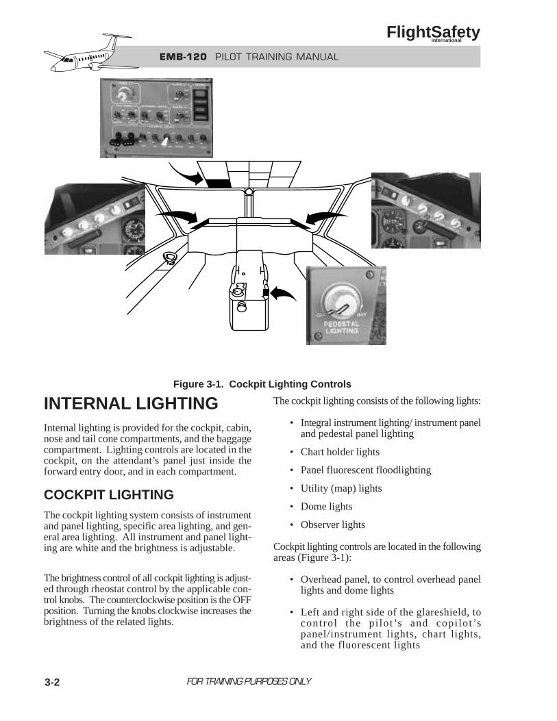
3-2
INTERNAL LIGHTINGInternal lighting is provided for the cockpit, cabin,nose and tail cone compartments, and the baggagecompartment. Lighting controls are located in thecockpit, on the attendant’s panel just inside theforward entry door, and in each compartment.
COCKPIT LIGHTINGThe cockpit lighting system consists of instrumentand panel lighting, specific area lighting, and gen-eral area lighting. All instrument and panel light-ing are white and the brightness is adjustable.
The brightness control of all cockpit lighting is adjust-ed through rheostat control by the applicable con-trol knobs. The counterclockwise position is the OFFposition. Turning the knobs clockwise increases thebrightness of the related lights.
The cockpit lighting consists of the following lights:
• Integral instrument lighting/ instrument paneland pedestal panel lighting
• Chart holder lights
• Panel fluorescent floodlighting
• Utility (map) lights
• Dome lights
• Observer lights
Cockpit lighting controls are located in the followingareas (Figure 3-1):
• Overhead panel, to control overhead panellights and dome lights
• Left and right side of the glareshield, tocontrol the pi lot’s and copi lot’spanel/instrument lights, chart lights,and the fluorescent lights
FOR TRAINING PURPOSES ONLY
EMB-120 PILOT TRAINING MANUAL
FlightSafety international
Figure 3-1. Cockpit Lighting Controls
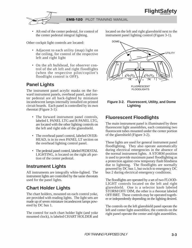
3-3
• Aft end of the center pedestal, for control ofthe center pedestal integral lighting.
Other cockpit light controls are located:
• Adjacent to each utility (map) light onthe ceiling, for control of the respectiveleft and right light
• On the aft bulkhead, for observer con-trol of the aft left and right floodlights(when the respective pilot/copilot’sfloodlight control is OFF).
Panel LightsThe instrument panel acrylic masks on the for-ward instrument panels, overhead panel, and cen-ter pedestal are all back-lighted by miniatureincandescent lamps internally installed on printedcircuit boards. Each panel is controlled by its ownrheostat (Figure 3-1):
• The forward instrument panel controls,labeled L PANEL LTG and R PANEL LTG,are located with the other lighting controls onthe left and right side of the glareshield.
• The overhead panel control, labeled OVER-HEAD, is in its own PANEL LT section onthe overhead lighting control panel.
• The pedestal panel control, labeled PEDESTALLIGHTING, is located on the right aft por-tion of the center pedestal.
Instrument LightsAll instruments are integrally white-lighted. Theinstrument lights are controlled by the same rheostatsused for the panel lights.
Chart Holder LightsThe chart holders, mounted on each control yoke,are provided with reading lights. The light sets aremade up of seven miniature incandescent lamps pow-ered by DC bus 1.
The control for each chart holder light (and yokemounted clock), is labeled CHART HOLDER and
located on the left and right glareshield next to theinstrument panel lighting control (Figure 3-1).
Figure 3-2. Fluorescent, Utility, and DomeLighting
Fluorescent FloodlightsThe main instrument panel is illuminated by threefluorescent light assemblies, each containing twofluorescent tubes mounted under the center portionof the glareshield (Figure 3-2).
These lights are used for general instrument panelfloodlighting. They also operate automaticallyduring electrical emergencies in the absence ofthe normal instrument lights. A STORM positionis used to provide maximum panel floodlighting asa protection against crew temporary flash blindnessdue to lightning. The floodlights are normallypowered by DC bus 1, but switch to emergency DCbus 2 during electrical emergency conditions.
The floodlights are operated by a set of two FLOOD-LIGHT controls located on the left and rightglareshield. One is a selector knob labeledSTORM/OFF/ DIM, the other is a rheostat labeledOFF/BRT. These controls may be operated togeth-er or independently depending on the lighting desired.
The controls on the left glareshield panel operate theleft and center light assemblies; the controls on theright panel operate the center and right assemblies.
FOR TRAINING PURPOSES ONLY
EMB-120 PILOT TRAINING MANUAL
FlightSafety international
UTILITY
DOME
FLUORESCENTFLOODLIGHTS
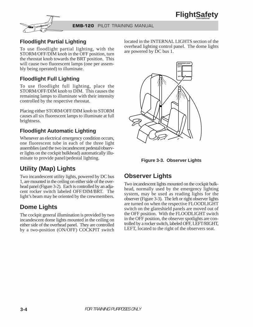
3-4
Floodlight Partial LightingTo use floodlight partial lighting, with theSTORM/OFF/DIM knob in the OFF position, turnthe rheostat knob towards the BRT position. Thiswill cause two fluorescent lamps (one per assem-bly being operated) to illuminate.
Floodlight Full LightingTo use floodlight full lighting, place theSTORM/OFF/DIM knob to DIM. This causes theremaining lamps to illuminate with their intensitycontrolled by the respective rheostat.
Placing either STORM/OFF/DIM knob to STORMcauses all six fluorescent lamps to illuminate at fullbrightness.
Floodlight Automatic LightingWhenever an electrical emergency condition occurs,one fluorescent tube in each of the three lightassemblies (and the two incandescent pedestal/observ-er lights on the cockpit bulkhead) automatically illu-minate to provide panel/pedestal lighting.
Utility (Map) LightsTwo incandescent utility lights, powered by DC bus1, are mounted in the ceiling on either side of the over-head panel (Figure 3-2). Each is controlled by an adja-cent rocker switch labeled OFF/DIM/BRT. Thelight’s beam may be oriented by the crewmembers.
Dome LightsThe cockpit general illumination is provided by twoincandescent dome lights mounted in the ceiling oneither side of the overhead panel. They are controlledby a two-position (ON/OFF) COCKPIT switch
located in the INTERNAL LIGHTS section of theoverhead lighting control panel. The dome lightsare powered by DC bus 1.
Figure 3-3. Observer Lights
Observer LightsTwo incandescent lights mounted on the cockpit bulk-head, normally used by the emergency lightingsystem, may be used as reading lights for theobserver (Figure 3-3). The left or right observer lightsare turned on when the respective FLOODLIGHTswitch on the glareshield panels are moved out ofthe OFF position. With the FLOODLIGHT switchin the OFF position, the observer spotlights are con-trolled by a rocker switch, labeled OFF, LEFT/RIGHT,LEFT, located to the right of the observers seat.
FOR TRAINING PURPOSES ONLY
EMB-120 PILOT TRAINING MANUAL
FlightSafety international
RIGHT/LEFT
OBSERVER LIGHT
LEFT
OFF
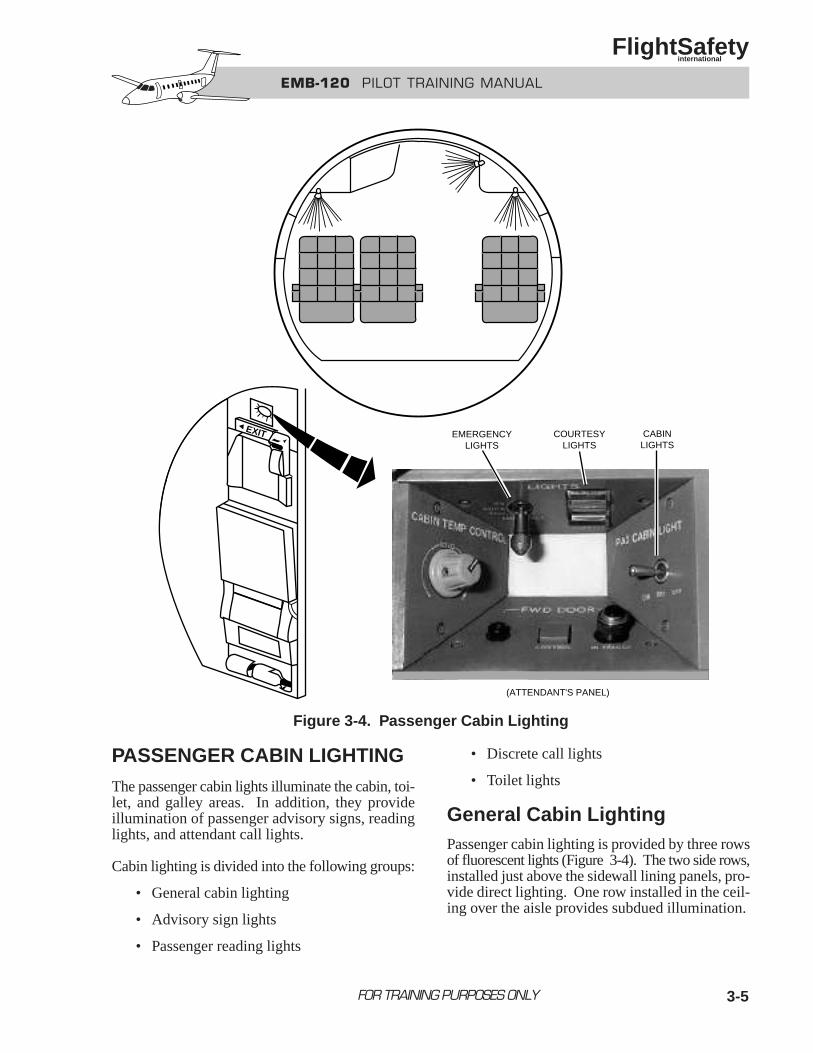
3-5
PASSENGER CABIN LIGHTINGThe passenger cabin lights illuminate the cabin, toi-let, and galley areas. In addition, they provideillumination of passenger advisory signs, readinglights, and attendant call lights.
Cabin lighting is divided into the following groups:
• General cabin lighting
• Advisory sign lights
• Passenger reading lights
• Discrete call lights
• Toilet lights
General Cabin LightingPassenger cabin lighting is provided by three rowsof fluorescent lights (Figure 3-4). The two side rows,installed just above the sidewall lining panels, pro-vide direct lighting. One row installed in the ceil-ing over the aisle provides subdued illumination.
FOR TRAINING PURPOSES ONLY
EMB-120 PILOT TRAINING MANUAL
FlightSafety international
(ATTENDANT'S PANEL)
EMERGENCYLIGHTS
COURTESYLIGHTS
CABINLIGHTS
EXIT
Figure 3-4. Passenger Cabin Lighting
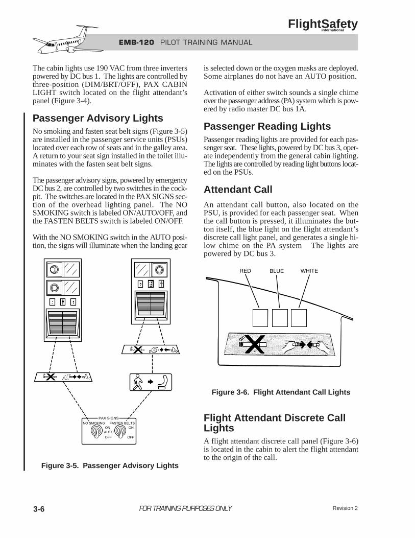
EMB-120 PILOT TRAINING MANUAL
FlightSafety international
3-6
The cabin lights use 190 VAC from three inverterspowered by DC bus 1. The lights are controlled bythree-position (DIM/BRT/OFF), PAX CABINLIGHT switch located on the flight attendant’spanel (Figure 3-4).
Passenger Advisory LightsNo smoking and fasten seat belt signs (Figure 3-5)are installed in the passenger service units (PSUs)located over each row of seats and in the galley area.A return to your seat sign installed in the toilet illu-minates with the fasten seat belt signs.
The passenger advisory signs, powered by emergencyDC bus 2, are controlled by two switches in the cock-pit. The switches are located in the PAX SIGNS sec-tion of the overhead lighting panel. The NOSMOKING switch is labeled ON/AUTO/OFF, andthe FASTEN BELTS switch is labeled ON/OFF.
With the NO SMOKING switch in the AUTO posi-tion, the signs will illuminate when the landing gear
Figure 3-5. Passenger Advisory Lights
is selected down or the oxygen masks are deployed.Some airplanes do not have an AUTO position.
Activation of either switch sounds a single chimeover the passenger address (PA) system which is pow-ered by radio master DC bus 1A.
Passenger Reading LightsPassenger reading lights are provided for each pas-senger seat. These lights, powered by DC bus 3, oper-ate independently from the general cabin lighting.The lights are controlled by reading light buttons locat-ed on the PSUs.
Attendant CallAn attendant call button, also located on thePSU, is provided for each passenger seat. Whenthe call button is pressed, it illuminates the but-ton itself, the blue light on the flight attendant’sdiscrete call light panel, and generates a single hi-low chime on the PA system The lights arepowered by DC bus 3.
Figure 3-6. Flight Attendant Call Lights
Flight Attendant Discrete CallLightsA flight attendant discrete call panel (Figure 3-6)is located in the cabin to alert the flight attendantto the origin of the call.
FOR TRAINING PURPOSES ONLY
NO SMOKING FASTEN BELTSON
AUTO
OFF
ON
OFF
PAX SIGNS
RED BLUE WHITE
Revision 2
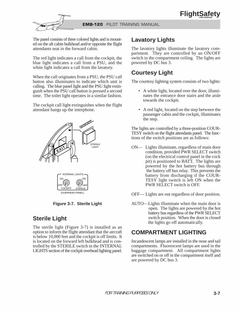
3-7
The panel consists of three colored lights and is mount-ed on the aft cabin bulkhead and/or opposite the flightattendants seat in the forward cabin.
The red light indicates a call from the cockpit, theblue light indicates a call from a PSU, and thewhite light indicates a call from the lavatory.
When the call originates from a PSU, the PSU callbutton also illuminates to indicate which unit iscalling. The blue panel light and the PSU light extin-guish when the PSU call button is pressed a secondtime. The toilet light operates in a similar fashion.
The cockpit call light extinguishes when the flightattendant hangs up the interphone.
Figure 3-7. Sterile Light
Sterile LightThe sterile light (Figure 3-7) is installed as anoption to inform the flight attendant that the aircraftis below 10,000 feet and the cockpit is off limits. Itis located on the forward left bulkhead and is con-trolled by the STERILE switch in the INTERNALLIGHTS section of the cockpit overhead lighting panel.
Lavatory LightsThe lavatory lights illuminate the lavatory com-partment. They are controlled by an ON/OFFswitch in the compartment ceiling. The lights arepowered by DC bus 3.
Courtesy LightThe courtesy lighting system consists of two lights:
• A white light, located over the door, illumi-nates the entrance door stairs and the aisletowards the cockpit.
• A red light, located on the step between thepassenger cabin and the cockpit, illuminatesthe step.
The lights are controlled by a three-position COUR-TESY switch on the flight attendants panel. The func-tions of the switch positions are as follows:
ON— Lights illuminate, regardless of main doorcondition, provided PWR SELECT switch(on the electrical control panel in the cockpit) is positioned to BATT. The lights arepowered by the hot battery bus throughthe battery off bus relay. This prevents thebattery from discharging if the COUR-TESY light switch is left ON when the PWR SELECT switch is OFF.
OFF— Lights are out regardless of door position.
AUTO—Lights illuminate when the main door isopen. The lights are powered by the hotbattery bus regardless of the PWR SELECTswitch position. When the door is closedthe lights go off automatically.
COMPARTMENT LIGHTINGIncandescent lamps are installed in the nose and tailcompartments. Fluorescent lamps are used in thebaggage compartment. All compartment lightsare switched on or off in the compartment itself andare powered by DC bus 3.
FOR TRAINING PURPOSES ONLY
EMB-120 PILOT TRAINING MANUAL
FlightSafety international
INTERNAL LIGHTS
ON
OFFCOCKPIT STERILE
ON
OFF
(OVERHEAD PANEL)
EXITSTERILE
LIGHT
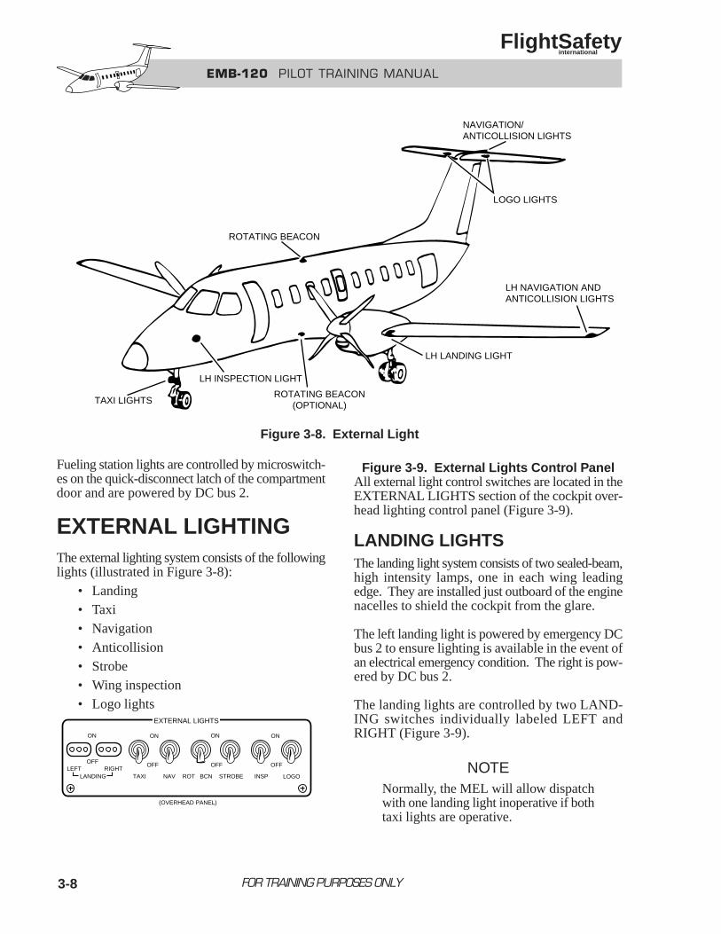
3-8
Fueling station lights are controlled by microswitch-es on the quick-disconnect latch of the compartmentdoor and are powered by DC bus 2.
EXTERNAL LIGHTINGThe external lighting system consists of the followinglights (illustrated in Figure 3-8):
• Landing• Taxi• Navigation• Anticollision• Strobe• Wing inspection• Logo lights
Figure 3-9. External Lights Control PanelAll external light control switches are located in theEXTERNAL LIGHTS section of the cockpit over-head lighting control panel (Figure 3-9).
LANDING LIGHTSThe landing light system consists of two sealed-beam,high intensity lamps, one in each wing leadingedge. They are installed just outboard of the enginenacelles to shield the cockpit from the glare.
The left landing light is powered by emergency DCbus 2 to ensure lighting is available in the event ofan electrical emergency condition. The right is pow-ered by DC bus 2.
The landing lights are controlled by two LAND-ING switches individually labeled LEFT andRIGHT (Figure 3-9).
NOTENormally, the MEL will allow dispatchwith one landing light inoperative if bothtaxi lights are operative.
FOR TRAINING PURPOSES ONLY
EMB-120 PILOT TRAINING MANUAL
FlightSafety international
ROTATING BEACON
NAVIGATION/ANTICOLLISION LIGHTS
LOGO LIGHTS
LH NAVIGATION ANDANTICOLLISION LIGHTS
LH LANDING LIGHT
ROTATING BEACON(OPTIONAL)
LH INSPECTION LIGHT
TAXI LIGHTS
Figure 3-8. External Light
ON
OFF
ON ON ON
OFF OFF OFF
TAXI NAV ROT BCN STROBE LOGOINSPLEFT RIGHT
LANDING
(OVERHEAD PANEL)
EXTERNAL LIGHTS
3-9
TAXI LIGHTSThe taxi light system consists of two sealed-beamlamps mounted on the nose landing gear oleo strut.One lamp has a wide beam and the other a narrowbeam to ensure that all reference angles are illuminatedwhile taxiing. The narrow beam lamp may also beconsidered a third landing light. The landing gearmust be locked down for the lights to illuminate.
The taxi lights are powered by DC bus 1 and are con-trolled by the TAXI switch (Figure 3-9).
NAVIGATION LIGHTSThe navigation lights system consists of six lights,two colored (aviation red and green) and fourwhite.
The red light is located in the left wing tip and thegreen in the right wing tip.
The four white lights are installed at the uppermost center point on the vertical tail (two above andtwo below the strobe light assembly). Regulatoryrequirements for view angles require that, becausethe strobe assembly is mounted between the upperand lower navigation lights, both an upper andlower white navigation light must be illuminated fornight operations.
The navigation lights are powered by DC bus 2 andare controlled by the NAV switch (Figure 3-9).
ROTATING BEACONSThe auxiliary anticollision light system consists oftwo red rotating beacons. One beacon is mountedon the upper surface of the fuselage center sectionand the other is mounted on the underside of the fuse-lage center section.
These 100-candle power lights are mounted onrotating platforms and enclosed under a red trans-parent cover. The lights and the motors whichturn the platforms are powered by DC bus 2.
The rotating beacons are controlled by the ROT BCNswitch (Figure 3-9).
STROBE LIGHTSThe main anticollision light system is the three400-candle power, white strobe lights, installed ineach wing tip and in the tail. The flash rate is 50per minute.
The strobes are normally off for ground operationas a courtesy to other aircraft.
NOTETurn off the strobe lights when operatingin clouds at night.
The strobe lights are powered by DC bus 1 and con-trolled by the STROBE switch (Figure 3-9).
WING INSPECTION LIGHTSThe wing inspection lights are two incandescent lightsinstalled on each side of the aircraft nose. They areused to inspect the wing leading edges and engineair inlets for ice formation. They are also used tovisually inspect the main landing gear.
The lights are powered by DC bus 2 and controlledby the INSP switch (Figure 3-9).
LOGO LIGHTSThe logo light system consists of two sealed-beamlights mounted in the horizontal stabilizer lower sur-face. They are used to illuminate a company logoor name on both sides of the vertical stabilizer.
The logo lights are powered by DC bus 3 and con-trolled by the LOGO switch (Figure 3-9).
FOR TRAINING PURPOSES ONLY
EMB-120 PILOT TRAINING MANUAL
FlightSafety international
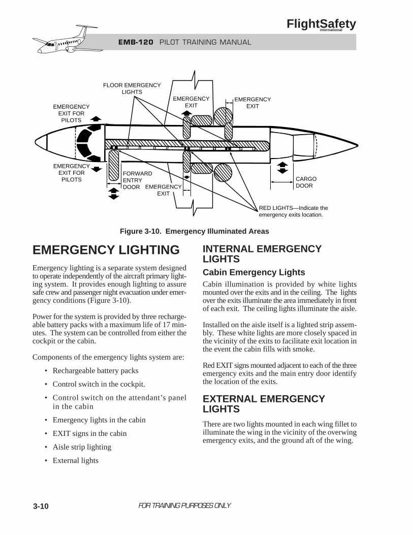
3-10
EMERGENCY LIGHTINGEmergency lighting is a separate system designedto operate independently of the aircraft primary light-ing system. It provides enough lighting to assuresafe crew and passenger night evacuation under emer-gency conditions (Figure 3-10).
Power for the system is provided by three recharge-able battery packs with a maximum life of 17 min-utes. The system can be controlled from either thecockpit or the cabin.
Components of the emergency lights system are:
• Rechargeable battery packs
• Control switch in the cockpit.
• Control switch on the attendant’s panelin the cabin
• Emergency lights in the cabin
• EXIT signs in the cabin
• Aisle strip lighting
• External lights
INTERNAL EMERGENCYLIGHTSCabin Emergency LightsCabin illumination is provided by white lightsmounted over the exits and in the ceiling. The lightsover the exits illuminate the area immediately in frontof each exit. The ceiling lights illuminate the aisle.
Installed on the aisle itself is a lighted strip assem-bly. These white lights are more closely spaced inthe vicinity of the exits to facilitate exit location inthe event the cabin fills with smoke.
Red EXIT signs mounted adjacent to each of the threeemergency exits and the main entry door identifythe location of the exits.
EXTERNAL EMERGENCYLIGHTSThere are two lights mounted in each wing fillet toilluminate the wing in the vicinity of the overwingemergency exits, and the ground aft of the wing.
FOR TRAINING PURPOSES ONLY
EMB-120 PILOT TRAINING MANUAL
FlightSafety international
EMERGENCYEXIT FORPILOTS
EMERGENCYEXIT FORPILOTS
FLOOR EMERGENCYLIGHTS
FORWARDENTRYDOOR
EMERGENCYEXIT
CARGODOOR
RED LIGHTS—Indicate theemergency exits location.
EMERGENCYEXIT
EMERGENCYEXIT
Figure 3-10. Emergency Illuminated Areas
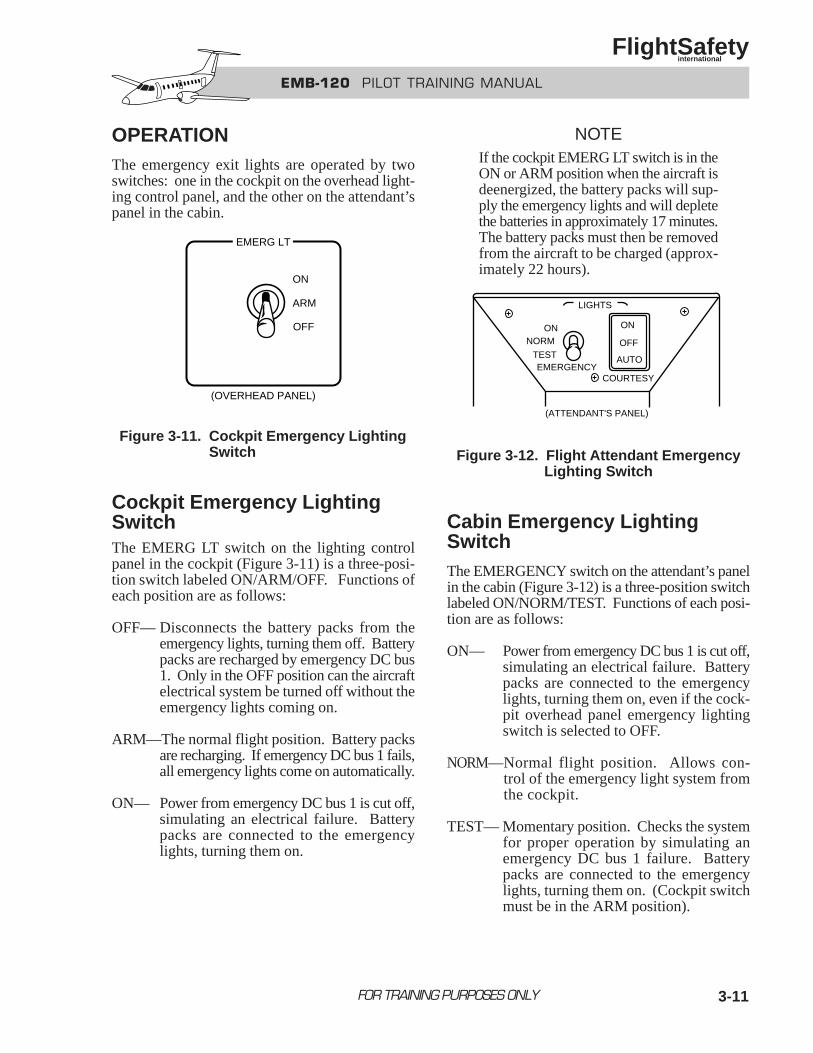
3-11
OPERATIONThe emergency exit lights are operated by twoswitches: one in the cockpit on the overhead light-ing control panel, and the other on the attendant’spanel in the cabin.
Figure 3-11. Cockpit Emergency LightingSwitch
Cockpit Emergency LightingSwitchThe EMERG LT switch on the lighting controlpanel in the cockpit (Figure 3-11) is a three-posi-tion switch labeled ON/ARM/OFF. Functions ofeach position are as follows:
OFF— Disconnects the battery packs from theemergency lights, turning them off. Batterypacks are recharged by emergency DC bus1. Only in the OFF position can the aircraftelectrical system be turned off without theemergency lights coming on.
ARM—The normal flight position. Battery packsare recharging. If emergency DC bus 1 fails,all emergency lights come on automatically.
ON— Power from emergency DC bus 1 is cut off,simulating an electrical failure. Batterypacks are connected to the emergency lights, turning them on.
NOTEIf the cockpit EMERG LT switch is in theON or ARM position when the aircraft isdeenergized, the battery packs will sup-ply the emergency lights and will depletethe batteries in approximately 17 minutes.The battery packs must then be removedfrom the aircraft to be charged (approx-imately 22 hours).
Figure 3-12. Flight Attendant EmergencyLighting Switch
Cabin Emergency LightingSwitchThe EMERGENCY switch on the attendant’s panelin the cabin (Figure 3-12) is a three-position switchlabeled ON/NORM/TEST. Functions of each posi-tion are as follows:
ON— Power from emergency DC bus 1 is cut off,simulating an electrical failure. Batterypacks are connected to the emergencylights, turning them on, even if the cock-pit overhead panel emergency lightingswitch is selected to OFF.
NORM—Normal flight position. Allows con-trol of the emergency light system fromthe cockpit.
TEST— Momentary position. Checks the systemfor proper operation by simulating anemergency DC bus 1 failure. Batterypacks are connected to the emergencylights, turning them on. (Cockpit switchmust be in the ARM position).
FOR TRAINING PURPOSES ONLY
EMB-120 PILOT TRAINING MANUAL
FlightSafety international
(OVERHEAD PANEL)
ON
ARM
OFF
EMERG LT
LIGHTS
(ATTENDANT'S PANEL)
ONNORM
TESTEMERGENCY
ON
OFF
AUTO
COURTESY
3-12
1. The EMB-120 has how many landing lights?A. 1B. 2C. 3D. 4
2. The EMB-120 has how many taxi lights?A. 1B. 2C. 3D. 4
3. Passenger cabin lighting is controlled by:A. A “PCL” switch located on the FO’s side
panelB. A “PCL” switch located on the captain’s
side panel.C. A three-position switch located on the
attendant’s panelD. All of the above
4. Taxi lights turn off automatically on landinggear retraction.A. TrueB. False
5. The flight attendant may be called from:A. The cockpitB. The cabinC. The lavatoryD. All of the above
6. The emergency lights come on if:
A. The cockpit switch is in ARM and emer-gency DC bus 1 fails.
B. The cockpit switch is placed to ON.C. The attendant’s switch is placed to ON,
regardless of the position of the cockpitswitch.
D. All of the above
FOR TRAINING PURPOSES ONLY
EMB-120 PILOT TRAINING MANUAL
FlightSafety international
QUESTIONS
4-iFOR TRAINING PURPOSES ONLY
EMB-120 PILOT TRAINING MANUAL
FlightSafety international
CHAPTER 4MASTER WARNING SYSTEM
CONTENTS
Page
INTRODUCTION ................................................................................................................... 4-1
GENERAL............................................................................................................................... 4-1
VISUAL WARNING SYSTEM .............................................................................................. 4-2
Multiple Alarm Panel ....................................................................................................... 4-2
WARNING and CAUTION Lights .................................................................................. 4-3
Alarm Cancel ................................................................................................................... 4-3
Alarm/Indication Lights ................................................................................................... 4-3
Alarm Lights Switch ........................................................................................................ 4-3
AURAL WARNING SYSTEM ............................................................................................... 4-4
Power On Self-Test .......................................................................................................... 4-5
Synthetic Voice Warnings ................................................................................................ 4-5
Additional Aural Alerts.................................................................................................... 4-5
Speakers and Audio System ............................................................................................ 4-6
WARNING SYSTEM OPERATION....................................................................................... 4-6
QUESTIONS ......................................................................................................................... 4-11
4-iii
ILLUSTRATIONS
Figure Title Page
4-1 Multiple Alarm Panel ............................................................................................. 4-2
4-2 WARNING/CAUTION Lights ............................................................................... 4-3
4-3 Alarm Lights Switch................................................................................................ 4-3
4-4 Aural Warning System (AWS) Interfaces .................................................................. 4-4
4-5 Multiple Alarm Panel Emergency Faults................................................................. 4-9
4-6 Multiple Alarm Panel Abnormal Faults ................................................................ 4-10
TABLE
Table Title Page
4-1 Emergency Faults .................................................................................................... 4-7
FOR TRAINING PURPOSES ONLY
EMB-120 PILOT TRAINING MANUAL
FlightSafety international
4-1
INTRODUCTIONThe master warning system on the EMB-120 includes a visual warning system and an aural warn-ing system to alert the crew of equipment malfunctions, unsafe operating conditions requiring imme-diate attention, as well as indication that a system is in operation. A stall warning system is also installed.
A color representation of all the panel annunciator lights is located in the ANNUNCIATOR PANELsection in the back of this manual.
GENERALThe visual warning system consists of two pair of mas-ter warning/caution lights on the glareshield, a cen-ter multiple alarm panel (MAP) to indicate individualsystem fault, and discrete alarm/indication lights.The aural warning system consists of voice warningsand a wide variety of other distinct aural alerts. Thecapability is provided to dim lights and to test and cancel most annunciation and aural warnings.
The stall warning system that provides continuousvisual information concerning the angle of attack;also aural warnings, control column shakers, and con-trol column pushers is covered in Chapter 15,Flight Controls.
TEST
FOR TRAINING PURPOSES ONLY
EMB-120 PILOT TRAINING MANUAL
FlightSafety international
CHAPTER 4MASTER WARNING SYSTEM
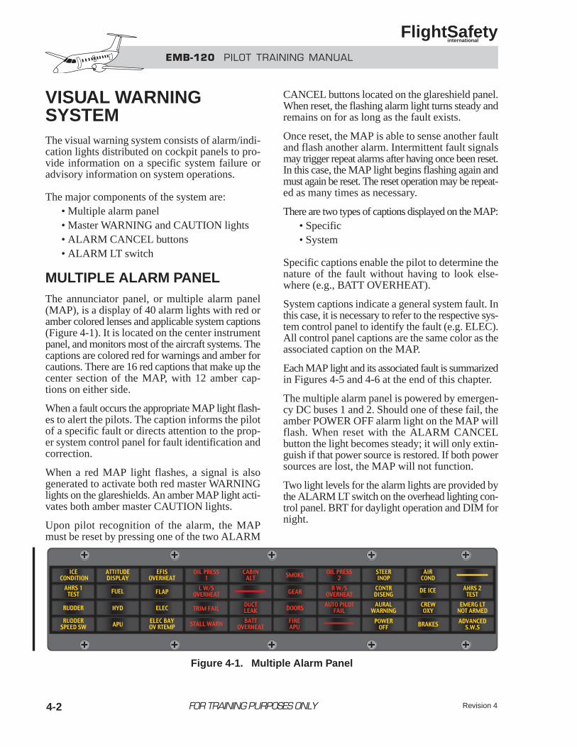
EMB-120 PILOT TRAINING MANUAL
FlightSafety international
Revision 44-2
VISUAL WARNINGSYSTEMThe visual warning system consists of alarm/indi-cation lights distributed on cockpit panels to pro-vide information on a specific system failure oradvisory information on system operations.
The major components of the system are:• Multiple alarm panel • Master WARNING and CAUTION lights• ALARM CANCEL buttons• ALARM LT switch
MULTIPLE ALARM PANELThe annunciator panel, or multiple alarm panel(MAP), is a display of 40 alarm lights with red oramber colored lenses and applicable system captions(Figure 4-1). It is located on the center instrumentpanel, and monitors most of the aircraft systems. Thecaptions are colored red for warnings and amber forcautions. There are 16 red captions that make up thecenter section of the MAP, with 12 amber cap-tions on either side.
When a fault occurs the appropriate MAP light flash-es to alert the pilots. The caption informs the pilotof a specific fault or directs attention to the prop-er system control panel for fault identification andcorrection.
When a red MAP light flashes, a signal is alsogenerated to activate both red master WARNINGlights on the glareshields. An amber MAP light acti-vates both amber master CAUTION lights.
Upon pilot recognition of the alarm, the MAPmust be reset by pressing one of the two ALARM
CANCEL buttons located on the glareshield panel.When reset, the flashing alarm light turns steady andremains on for as long as the fault exists.
Once reset, the MAP is able to sense another faultand flash another alarm. Intermittent fault signalsmay trigger repeat alarms after having once been reset.In this case, the MAP light begins flashing again andmust again be reset. The reset operation may be repeat-ed as many times as necessary.
There are two types of captions displayed on the MAP:• Specific• System
Specific captions enable the pilot to determine thenature of the fault without having to look else-where (e.g., BATT OVERHEAT).
System captions indicate a general system fault. Inthis case, it is necessary to refer to the respective sys-tem control panel to identify the fault (e.g. ELEC).All control panel captions are the same color as theassociated caption on the MAP.
Each MAP light and its associated fault is summarizedin Figures 4-5 and 4-6 at the end of this chapter.
The multiple alarm panel is powered by emergen-cy DC buses 1 and 2. Should one of these fail, theamber POWER OFF alarm light on the MAP willflash. When reset with the ALARM CANCELbutton the light becomes steady; it will only extin-guish if that power source is restored. If both powersources are lost, the MAP will not function.
Two light levels for the alarm lights are provided bythe ALARM LT switch on the overhead lighting con-trol panel. BRT for daylight operation and DIM fornight.
FOR TRAINING PURPOSES ONLY
Figure 4-1. Multiple Alarm Panel
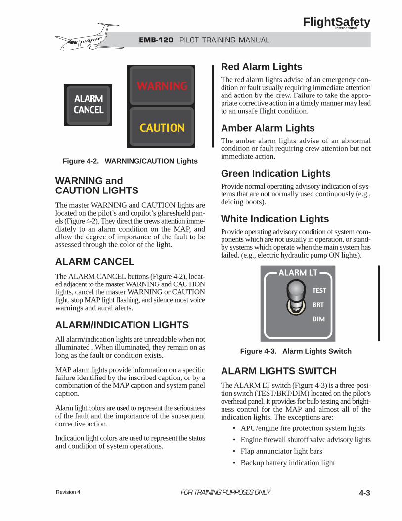
Revision 4 4-3
WARNING andCAUTION LIGHTSThe master WARNING and CAUTION lights arelocated on the pilot’s and copilot’s glareshield pan-els (Figure 4-2). They direct the crews attention imme-diately to an alarm condition on the MAP, andallow the degree of importance of the fault to beassessed through the color of the light.
ALARM CANCELThe ALARM CANCEL buttons (Figure 4-2), locat-ed adjacent to the master WARNING and CAUTIONlights, cancel the master WARNING or CAUTIONlight, stop MAP light flashing, and silence most voicewarnings and aural alerts.
ALARM/INDICATION LIGHTSAll alarm/indication lights are unreadable when notilluminated . When illuminated, they remain on aslong as the fault or condition exists.
MAP alarm lights provide information on a specificfailure identified by the inscribed caption, or by acombination of the MAP caption and system panelcaption.
Alarm light colors are used to represent the seriousnessof the fault and the importance of the subsequentcorrective action.
Indication light colors are used to represent the statusand condition of system operations.
Red Alarm LightsThe red alarm lights advise of an emergency con-dition or fault usually requiring immediate attentionand action by the crew. Failure to take the appro-priate corrective action in a timely manner may leadto an unsafe flight condition.
Amber Alarm LightsThe amber alarm lights advise of an abnormalcondition or fault requiring crew attention but notimmediate action.
Green Indication LightsProvide normal operating advisory indication of sys-tems that are not normally used continuously (e.g.,deicing boots).
White Indication LightsProvide operating advisory condition of system com-ponents which are not usually in operation, or stand-by systems which operate when the main system hasfailed. (e.g., electric hydraulic pump ON lights).
ALARM LIGHTS SWITCHThe ALARM LT switch (Figure 4-3) is a three-posi-tion switch (TEST/BRT/DIM) located on the pilot’soverhead panel. It provides for bulb testing and bright-ness control for the MAP and almost all of theindication lights. The exceptions are:
• APU/engine fire protection system lights
• Engine firewall shutoff valve advisory lights
• Flap annunciator light bars
• Backup battery indication light
EMB-120 PILOT TRAINING MANUAL
FlightSafety international
FOR TRAINING PURPOSES ONLY
Figure 4-2. WARNING/CAUTION Lights
Figure 4-3. Alarm Lights Switch
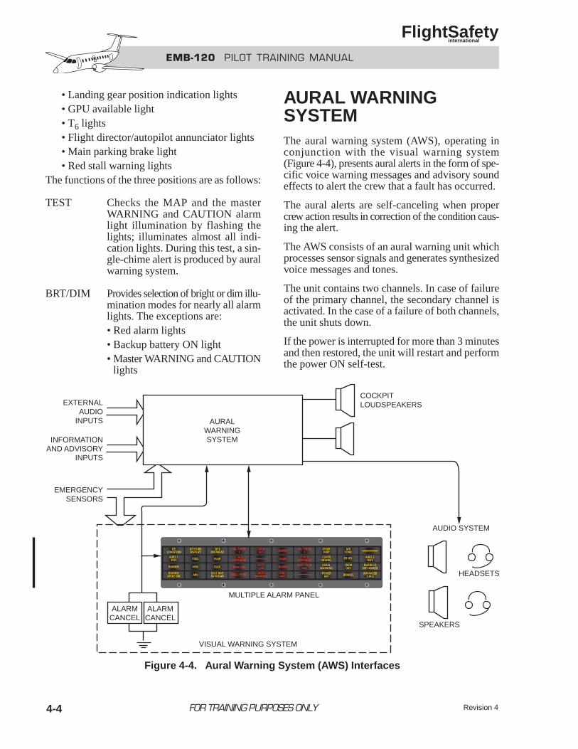
EMB-120 PILOT TRAINING MANUAL
FlightSafety international
Revision 44-4
• Landing gear position indication lights• GPU available light• T6 lights• Flight director/autopilot annunciator lights• Main parking brake light• Red stall warning lights
The functions of the three positions are as follows:
TEST Checks the MAP and the masterWARNING and CAUTION alarmlight illumination by flashing thelights; illuminates almost all indi-cation lights. During this test, a sin-gle-chime alert is produced by auralwarning system.
BRT/DIM Provides selection of bright or dim illu-mination modes for nearly all alarmlights. The exceptions are:• Red alarm lights• Backup battery ON light• Master WARNING and CAUTION
lights
AURAL WARNINGSYSTEMThe aural warning system (AWS), operating inconjunction with the visual warning system(Figure 4-4), presents aural alerts in the form of spe-cific voice warning messages and advisory soundeffects to alert the crew that a fault has occurred.
The aural alerts are self-canceling when propercrew action results in correction of the condition caus-ing the alert.
The AWS consists of an aural warning unit whichprocesses sensor signals and generates synthesizedvoice messages and tones.
The unit contains two channels. In case of failureof the primary channel, the secondary channel isactivated. In the case of a failure of both channels,the unit shuts down.
If the power is interrupted for more than 3 minutesand then restored, the unit will restart and performthe power ON self-test.
FOR TRAINING PURPOSES ONLY
ALARMCANCEL
ALARMCANCEL
HEADSETS
SPEAKERS
AUDIO SYSTEM
COCKPITLOUDSPEAKERSEXTERNAL
AUDIOINPUTS
EMERGENCYSENSORS
AURALWARNINGSYSTEMINFORMATION
AND ADVISORYINPUTS
MULTIPLE ALARM PANEL
VISUAL WARNING SYSTEM
Figure 4-4. Aural Warning System (AWS) Interfaces
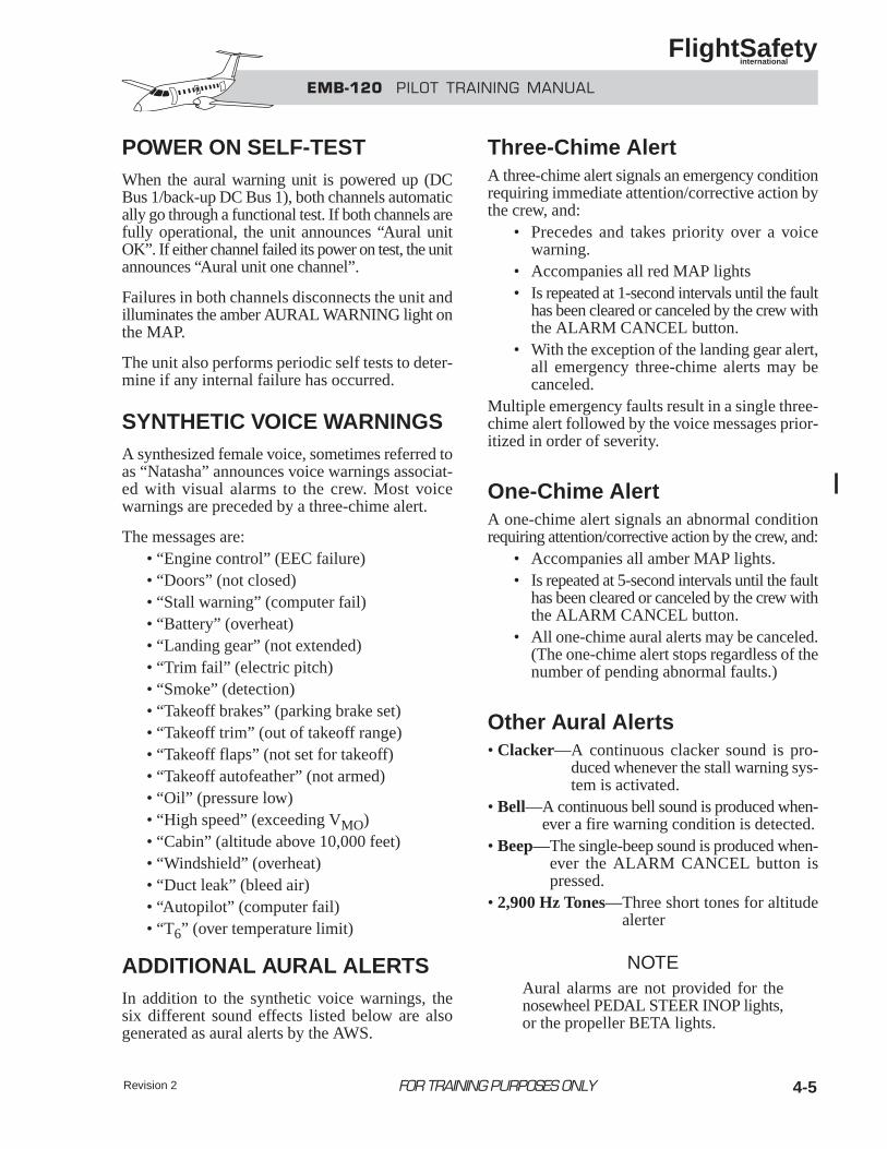
4-5
POWER ON SELF-TESTWhen the aural warning unit is powered up (DCBus 1/back-up DC Bus 1), both channels automatically go through a functional test. If both channels arefully operational, the unit announces “Aural unitOK”. If either channel failed its power on test, the unitannounces “Aural unit one channel”.
Failures in both channels disconnects the unit andilluminates the amber AURAL WARNING light onthe MAP.
The unit also performs periodic self tests to deter-mine if any internal failure has occurred.
SYNTHETIC VOICE WARNINGSA synthesized female voice, sometimes referred toas “Natasha” announces voice warnings associat-ed with visual alarms to the crew. Most voicewarnings are preceded by a three-chime alert.
The messages are:• “Engine control” (EEC failure)• “Doors” (not closed)• “Stall warning” (computer fail)• “Battery” (overheat)• “Landing gear” (not extended)• “Trim fail” (electric pitch)• “Smoke” (detection)• “Takeoff brakes” (parking brake set)• “Takeoff trim” (out of takeoff range)• “Takeoff flaps” (not set for takeoff)• “Takeoff autofeather” (not armed)• “Oil” (pressure low)• “High speed” (exceeding VMO)• “Cabin” (altitude above 10,000 feet)• “Windshield” (overheat)• “Duct leak” (bleed air)• “Autopilot” (computer fail)• “T6” (over temperature limit)
ADDITIONAL AURAL ALERTSIn addition to the synthetic voice warnings, thesix different sound effects listed below are alsogenerated as aural alerts by the AWS.
Three-Chime AlertA three-chime alert signals an emergency conditionrequiring immediate attention/corrective action bythe crew, and:
• Precedes and takes priority over a voicewarning.
• Accompanies all red MAP lights• Is repeated at 1-second intervals until the fault
has been cleared or canceled by the crew withthe ALARM CANCEL button.
• With the exception of the landing gear alert,all emergency three-chime alerts may becanceled.
Multiple emergency faults result in a single three-chime alert followed by the voice messages prior-itized in order of severity.
One-Chime AlertA one-chime alert signals an abnormal conditionrequiring attention/corrective action by the crew, and:
• Accompanies all amber MAP lights.• Is repeated at 5-second intervals until the fault
has been cleared or canceled by the crew withthe ALARM CANCEL button.
• All one-chime aural alerts may be canceled.(The one-chime alert stops regardless of thenumber of pending abnormal faults.)
Other Aural Alerts• Clacker—A continuous clacker sound is pro-
duced whenever the stall warning sys-tem is activated.
• Bell—A continuous bell sound is produced when-ever a fire warning condition is detected.
• Beep—The single-beep sound is produced when-ever the ALARM CANCEL button ispressed.
• 2,900 Hz Tones—Three short tones for altitudealerter
NOTEAural alarms are not provided for thenosewheel PEDAL STEER INOP lights,or the propeller BETA lights.
EMB-120 PILOT TRAINING MANUAL
FlightSafety international
FOR TRAINING PURPOSES ONLY Revision 2
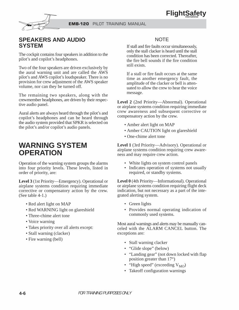
EMB-120 PILOT TRAINING MANUAL
FlightSafety international
4-6
SPEAKERS AND AUDIOSYSTEM The cockpit contains four speakers in addition to thepilot’s and copilot’s headphones.
Two of the four speakers are driven exclusively bythe aural warning unit and are called the AWSpilot’s and AWS copilot’s loudspeaker. There is noprovision for crew adjustment of the AWS speakervolume, nor can they be turned off.
The remaining two speakers, along with thecrewmember headphones, are driven by their respec-tive audio panel.
Aural alerts are always heard through the pilot’s andcopilot’s headphones and can be heard throughthe audio system provided that SPKR is selected onthe pilot’s and/or copilot’s audio panels.
WARNING SYSTEMOPERATIONOperation of the warning system groups the alarmsinto four priority levels. These levels, listed inorder of priority, are:
Level 3 (1st Priority—Emergency). Operational orairplane systems condition requiring immediatecorrective or compensatory action by the crew.(See table 4-1.)
• Red alert light on MAP• Red WARNING light on glareshield• Three-chime alert tone• Voice warning• Takes priority over all alerts except:• Stall warning (clacker)• Fire warning (bell)
NOTEIf stall and fire faults occur simultaneously,only the stall clacker is heard until the stallcondition has been corrected. Thereafter,the fire bell sounds if the fire conditionstill exists.
If a stall or fire fault occurs at the sametime as another emergency fault, theamplitude of the clacker or bell is atten-uated to allow the crew to hear the voicemessage.
Level 2 (2nd Priority—Abnormal). Operationalor airplane systems condition requiring immediatecrew awareness and subsequent corrective orcompensatory action by the crew.
• Amber alert light on MAP• Amber CAUTION light on glareshield• One-chime alert tone
Level 1 (3rd Priority—Advisory). Operational orairplane systems condition requiring crew aware-ness and may require crew action.
• White lights on system control panels• Indicates operation of systems not usually
required, or standby systems.
Level 0 (4th Priority—Informational). Operationalor airplane systems condition requiring flight deckindication, but not necessary as a part of the inte-grated alerting system.
• Green lights• Provides normal operating indication of
commonly used systems.
Most aural warnings and alerts may be manually can-celed with the ALARM CANCEL button. Theexceptions are:
• Stall warning clacker• “Glide slope” (below)• “Landing gear” (not down locked with flap
position greater than 17°)• “High speed” (exceeding VMO)• Takeoff configuration warnings
FOR TRAINING PURPOSES ONLY
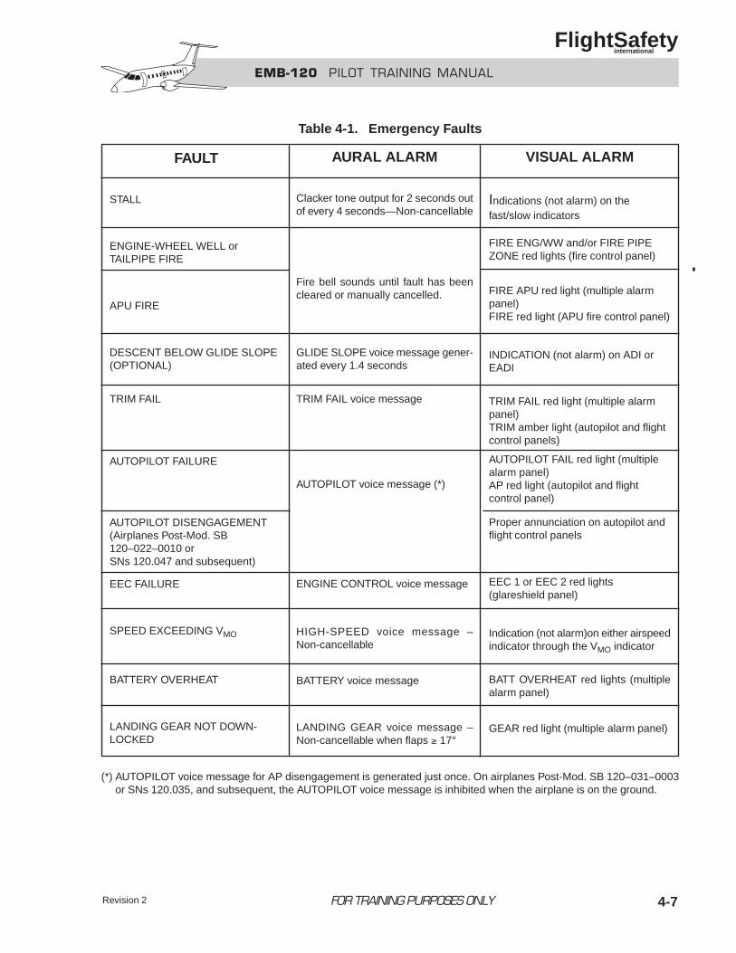
FOR TRAINING PURPOSES ONLY
EMB-120 PILOT TRAINING MANUAL
FlightSafety international
4-7
Table 4-1. Emergency Faults
FAULT
STALL
ENGINE-WHEEL WELL or TAILPIPE FIRE
APU FIRE
DESCENT BELOW GLIDE SLOPE(OPTIONAL)
TRIM FAIL
AUTOPILOT FAILURE
AUTOPILOT DISENGAGEMENT(Airplanes Post-Mod. SB120–022–0010 or SNs 120.047 and subsequent)
EEC FAILURE
SPEED EXCEEDING VMO
BATTERY OVERHEAT
LANDING GEAR NOT DOWN-LOCKED
AURAL ALARM
Clacker tone output for 2 seconds outof every 4 seconds—Non-cancellable
Fire bell sounds until fault has beencleared or manually cancelled.
GLIDE SLOPE voice message gener-ated every 1.4 seconds
TRIM FAIL voice message
AUTOPILOT voice message (*)
ENGINE CONTROL voice message
HIGH-SPEED voice message –Non-cancellable
BATTERY voice message
LANDING GEAR voice message –Non-cancellable when flaps ≥ 17°
VISUAL ALARM
Indications (not alarm) on thefast/slow indicators
FIRE ENG/WW and/or FIRE PIPEZONE red lights (fire control panel)
FIRE APU red light (multiple alarmpanel)FIRE red light (APU fire control panel)
INDICATION (not alarm) on ADI orEADI
TRIM FAIL red light (multiple alarmpanel)TRIM amber light (autopilot and flightcontrol panels)
AUTOPILOT FAIL red light (multiplealarm panel)AP red light (autopilot and flightcontrol panel)
Proper annunciation on autopilot andflight control panels
EEC 1 or EEC 2 red lights(glareshield panel)
Indication (not alarm)on either airspeedindicator through the VMO indicator
BATT OVERHEAT red lights (multiplealarm panel)
GEAR red light (multiple alarm panel)
(*) AUTOPILOT voice message for AP disengagement is generated just once. On airplanes Post-Mod. SB 120–031–0003or SNs 120.035, and subsequent, the AUTOPILOT voice message is inhibited when the airplane is on the ground.
Revision 2
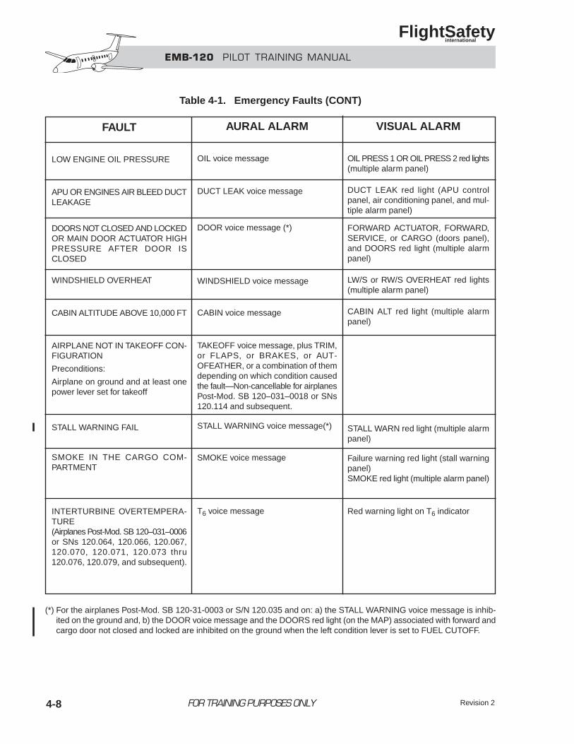
EMB-120 PILOT TRAINING MANUAL
FlightSafety international
FOR TRAINING PURPOSES ONLY 4-8
Table 4-1. Emergency Faults (CONT)
FAULT
LOW ENGINE OIL PRESSURE
APU OR ENGINES AIR BLEED DUCTLEAKAGE
DOORS NOT CLOSED AND LOCKEDOR MAIN DOOR ACTUATOR HIGHPRESSURE AFTER DOOR ISCLOSED
WINDSHIELD OVERHEAT
CABIN ALTITUDE ABOVE 10,000 FT
AIRPLANE NOT IN TAKEOFF CON-FIGURATION
Preconditions:
Airplane on ground and at least onepower lever set for takeoff
STALL WARNING FAIL
SMOKE IN THE CARGO COM-PARTMENT
INTERTURBINE OVERTEMPERA-TURE(Airplanes Post-Mod. SB 120–031–0006or SNs 120.064, 120.066, 120.067,120.070, 120.071, 120.073 thru120.076, 120.079, and subsequent).
AURAL ALARM
OIL voice message
DUCT LEAK voice message
DOOR voice message (*)
WINDSHIELD voice message
CABIN voice message
TAKEOFF voice message, plus TRIM,or FLAPS, or BRAKES, or AUT-OFEATHER, or a combination of themdepending on which condition causedthe fault—Non-cancellable for airplanesPost-Mod. SB 120–031–0018 or SNs120.114 and subsequent.
STALL WARNING voice message(*)
SMOKE voice message
T6 voice message
VISUAL ALARM
OIL PRESS 1 OR OIL PRESS 2 red lights(multiple alarm panel)
DUCT LEAK red light (APU controlpanel, air conditioning panel, and mul-tiple alarm panel)
FORWARD ACTUATOR, FORWARD,SERVICE, or CARGO (doors panel),and DOORS red light (multiple alarmpanel)
LW/S or RW/S OVERHEAT red lights(multiple alarm panel)
CABIN ALT red light (multiple alarmpanel)
STALL WARN red light (multiple alarmpanel)
Failure warning red light (stall warningpanel)SMOKE red light (multiple alarm panel)
Red warning light on T6 indicator
(*) For the airplanes Post-Mod. SB 120-31-0003 or S/N 120.035 and on: a) the STALL WARNING voice message is inhib-ited on the ground and, b) the DOOR voice message and the DOORS red light (on the MAP) associated with forward andcargo door not closed and locked are inhibited on the ground when the left condition lever is set to FUEL CUTOFF.
Revision 2
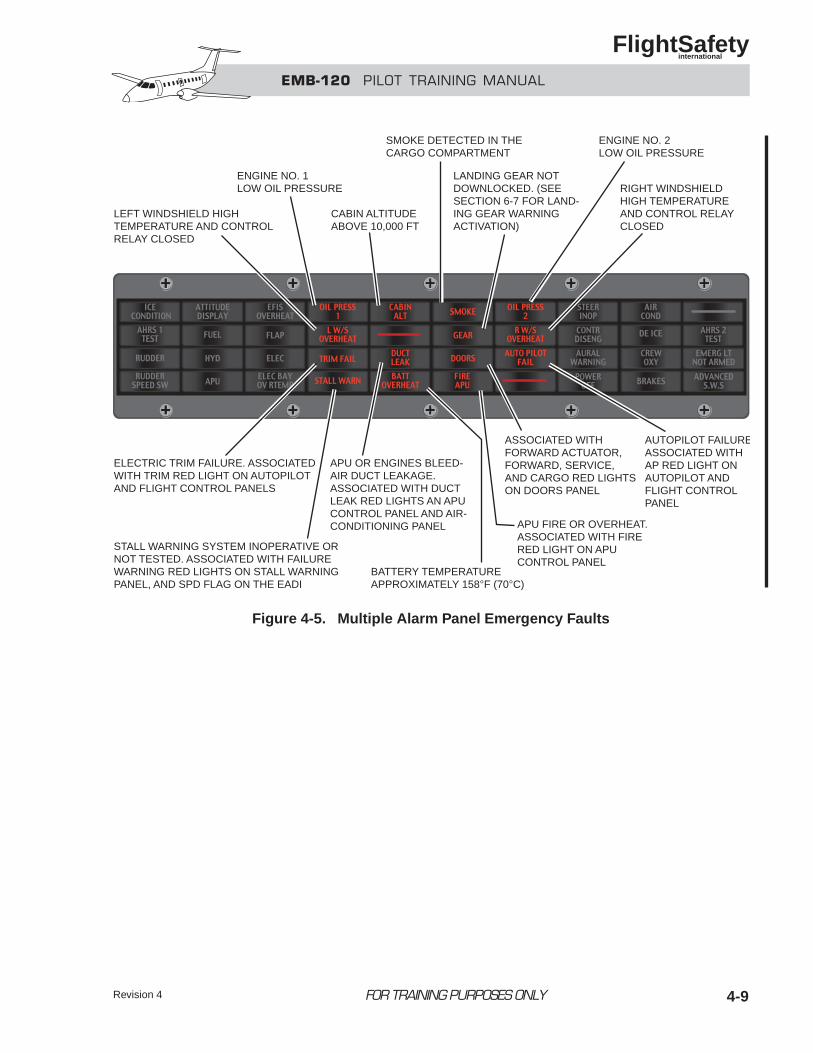
Revision 4 4-9
EMB-120 PILOT TRAINING MANUAL
FlightSafety international
FOR TRAINING PURPOSES ONLY
ELECTRIC TRIM FAILURE. ASSOCIATEDWITH TRIM RED LIGHT ON AUTOPILOTAND FLIGHT CONTROL PANELS
APU OR ENGINES BLEED-AIR DUCT LEAKAGE.ASSOCIATED WITH DUCTLEAK RED LIGHTS AN APUCONTROL PANEL AND AIR-CONDITIONING PANEL
STALL WARNING SYSTEM INOPERATIVE ORNOT TESTED. ASSOCIATED WITH FAILUREWARNING RED LIGHTS ON STALL WARNINGPANEL, AND SPD FLAG ON THE EADI
ASSOCIATED WITHFORWARD ACTUATOR,FORWARD, SERVICE,AND CARGO RED LIGHTSON DOORS PANEL
AUTOPILOT FAILUREASSOCIATED WITHAP RED LIGHT ONAUTOPILOT ANDFLIGHT CONTROLPANEL
BATTERY TEMPERATUREAPPROXIMATELY 158°F (70°C)
APU FIRE OR OVERHEAT.ASSOCIATED WITH FIRERED LIGHT ON APUCONTROL PANEL
LEFT WINDSHIELD HIGHTEMPERATURE AND CONTROLRELAY CLOSED
ENGINE NO. 1LOW OIL PRESSURE
CABIN ALTITUDEABOVE 10,000 FT
SMOKE DETECTED IN THECARGO COMPARTMENT
LANDING GEAR NOTDOWNLOCKED. (SEESECTION 6-7 FOR LAND-ING GEAR WARNINGACTIVATION)
RIGHT WINDSHIELDHIGH TEMPERATUREAND CONTROL RELAYCLOSED
ENGINE NO. 2LOW OIL PRESSURE
Figure 4-5. Multiple Alarm Panel Emergency Faults
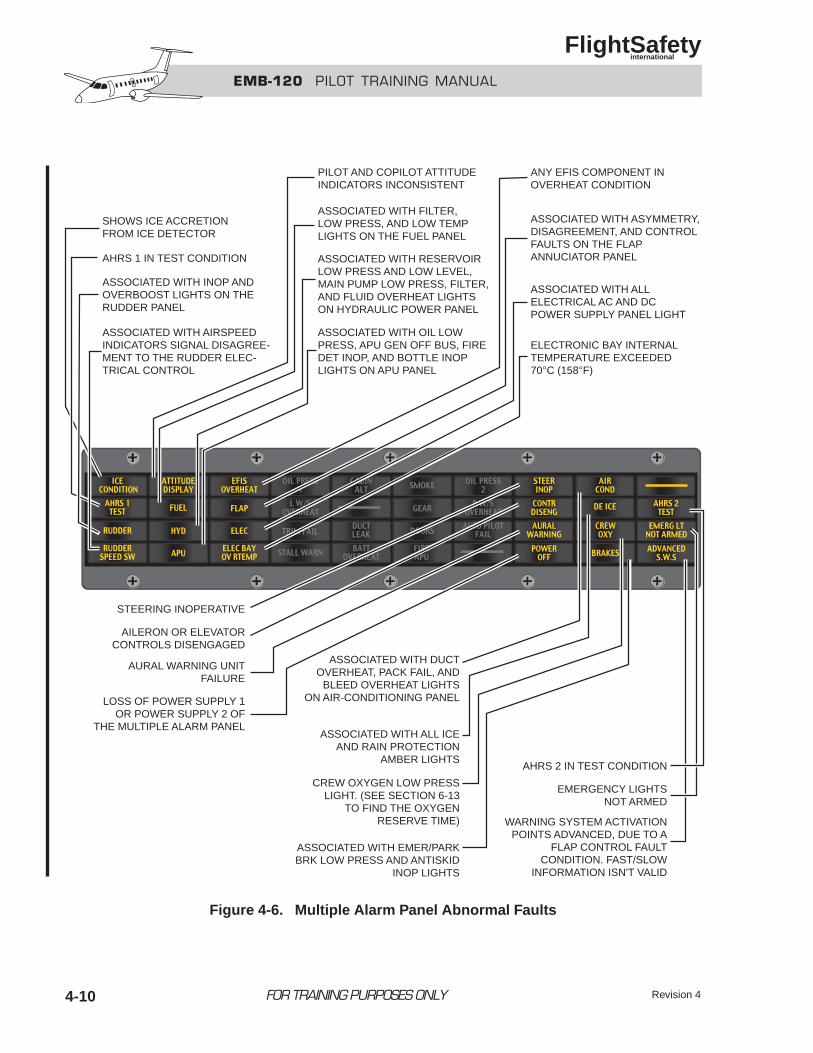
Revision 44-10 FOR TRAINING PURPOSES ONLY
EMB-120 PILOT TRAINING MANUAL
FlightSafety international
SHOWS ICE ACCRETIONFROM ICE DETECTOR
AHRS 1 IN TEST CONDITION
ASSOCIATED WITH INOP ANDOVERBOOST LIGHTS ON THERUDDER PANEL
ASSOCIATED WITH AIRSPEEDINDICATORS SIGNAL DISAGREE-MENT TO THE RUDDER ELEC-TRICAL CONTROL
PILOT AND COPILOT ATTITUDEINDICATORS INCONSISTENT
ASSOCIATED WITH FILTER,LOW PRESS, AND LOW TEMPLIGHTS ON THE FUEL PANEL
ASSOCIATED WITH OIL LOWPRESS, APU GEN OFF BUS, FIREDET INOP, AND BOTTLE INOPLIGHTS ON APU PANEL
ASSOCIATED WITH RESERVOIRLOW PRESS AND LOW LEVEL,MAIN PUMP LOW PRESS, FILTER,AND FLUID OVERHEAT LIGHTSON HYDRAULIC POWER PANEL
ANY EFIS COMPONENT INOVERHEAT CONDITION
ASSOCIATED WITH ALLELECTRICAL AC AND DCPOWER SUPPLY PANEL LIGHT
ELECTRONIC BAY INTERNALTEMPERATURE EXCEEDED70°C (158°F)
ASSOCIATED WITH ASYMMETRY,DISAGREEMENT, AND CONTROLFAULTS ON THE FLAPANNUCIATOR PANEL
AHRS 2 IN TEST CONDITION
STEERING INOPERATIVE
ASSOCIATED WITH DUCTOVERHEAT, PACK FAIL, AND
BLEED OVERHEAT LIGHTSON AIR-CONDITIONING PANEL
ASSOCIATED WITH ALL ICEAND RAIN PROTECTION
AMBER LIGHTS
ASSOCIATED WITH EMER/PARKBRK LOW PRESS AND ANTISKID
INOP LIGHTS
CREW OXYGEN LOW PRESSLIGHT. (SEE SECTION 6-13
TO FIND THE OXYGENRESERVE TIME)
AILERON OR ELEVATORCONTROLS DISENGAGED
AURAL WARNING UNITFAILURE
LOSS OF POWER SUPPLY 1OR POWER SUPPLY 2 OF
THE MULTIPLE ALARM PANEL
EMERGENCY LIGHTSNOT ARMED
WARNING SYSTEM ACTIVATIONPOINTS ADVANCED, DUE TO A
FLAP CONTROL FAULTCONDITION. FAST/SLOW
INFORMATION ISN'T VALID
Figure 4-6. Multiple Alarm Panel Abnormal Faults
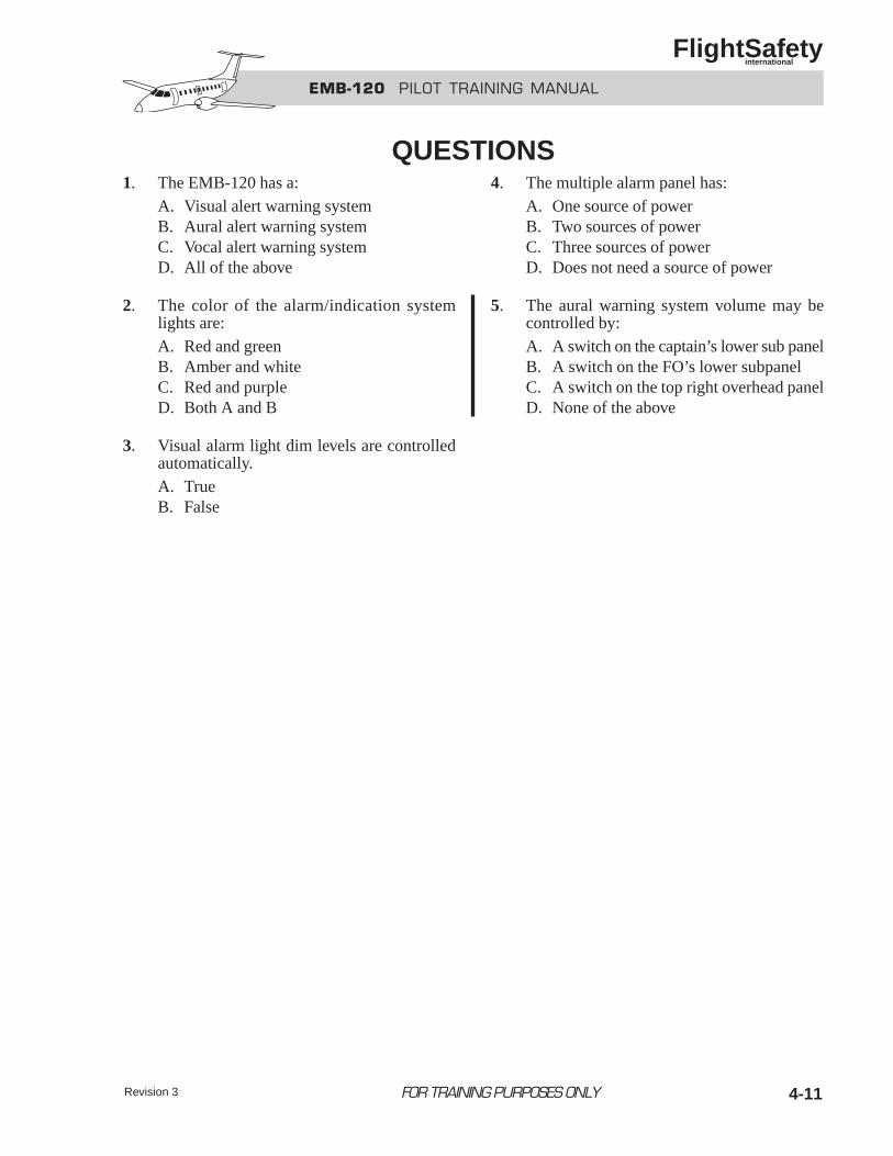
Revision 3 4-11
1. The EMB-120 has a:A. Visual alert warning systemB. Aural alert warning systemC. Vocal alert warning systemD. All of the above
2. The color of the alarm/indication systemlights are:A. Red and greenB. Amber and whiteC. Red and purpleD. Both A and B
3. Visual alarm light dim levels are controlledautomatically.A. TrueB. False
4. The multiple alarm panel has:A. One source of powerB. Two sources of powerC. Three sources of powerD. Does not need a source of power
5. The aural warning system volume may becontrolled by:A. A switch on the captain’s lower sub panelB. A switch on the FO’s lower subpanelC. A switch on the top right overhead panelD. None of the above
EMB-120 PILOT TRAINING MANUAL
FlightSafety international
FOR TRAINING PURPOSES ONLY
QUESTIONS
EMB-120 PILOT TRAINING MANUAL
FlightSafety international
FOR TRAINING PURPOSES ONLY 5-i
CHAPTER 5FUEL SYSTEM
CONTENTS
Page
INTRODUCTION ................................................................................................................... 5-1
GENERAL............................................................................................................................... 5-1
FUEL STORAGE SYSTEM.................................................................................................... 5-2
General ............................................................................................................................. 5-2
Fuel Tanks ........................................................................................................................ 5-2
Fuel Tank Venting ............................................................................................................ 5-3
FUEL FEED SYSTEM............................................................................................................ 5-3
General ............................................................................................................................. 5-3
Fuel Pumps....................................................................................................................... 5-5
Fuel System Valves .......................................................................................................... 5-6
Engine Fuel Feed System................................................................................................. 5-7
APU Fuel Feed System .................................................................................................... 5-9
FUEL SYSTEM CONTROL AND MONITORING............................................................... 5-9
Fuel Control Panel............................................................................................................ 5-9
Fuel Management Panel ................................................................................................... 5-9
Fuel Quantity Indication................................................................................................... 5-9
Fuel Flow Indicators ...................................................................................................... 5-11
Fuel Totalizer ................................................................................................................. 5-11
OPERATION......................................................................................................................... 5-12
Normal ........................................................................................................................... 5-12
Crossfeed........................................................................................................................ 5-13
FUEL SERVICING ............................................................................................................... 5-14
Refueling........................................................................................................................ 5-14
Defueling........................................................................................................................ 5-19
QUESTIONS ......................................................................................................................... 5-23
5-iii
ILLUSTRATIONS
Figure Title Page
5-1 Fuel Storage ............................................................................................................. 5-2
5-2 Fuel Feed System ..................................................................................................... 5-4
5-3 Jet Pump .................................................................................................................. 5-5
5-4 Engine Fuel Feed System ........................................................................................ 5-7
5-5 Fuel Control Panel ................................................................................................... 5-9
5-6 Fuel Management Panel .......................................................................................... 5-9
5-7 Fuel Quantity Measuring Stick .............................................................................. 5-10
5-8 Fuel Totalizer ......................................................................................................... 5-11
5-9 Fuel System Operation During Start ..................................................................... 5-12
5-10 Fuel System Normal Operation ............................................................................. 5-12
5-11 Fuel System Crossfeed .......................................................................................... 5-13
5-12 Fueling Panel ......................................................................................................... 5-14
5-13 Refueling System .................................................................................................. 5-15
5-14 Refueling Adapter ................................................................................................. 5-15
5-15 Refueling Vent Valve ............................................................................................. 5-16
5-16 Pilot Valve ............................................................................................................. 5-16
5-17 Refueling Shutoff Valve ........................................................................................ 5-16
5-18 Refueling System Operation ................................................................................. 5-17
5-19 Defueling System .................................................................................................. 5-19
5-20 Overhead Fuel Panel .............................................................................................. 5-21
5-21 Underwing Fueling Panel ...................................................................................... 5-22
FOR TRAINING PURPOSES ONLY
EMB-120 PILOT TRAINING MANUAL
FlightSafety international
5-1
INTRODUCTIONThe EMB-120 Brasilia fuel system provides a means for storing fuel and distributing it to the enginesand the auxiliary power unit. The fuel system is actually two seperate and identical systems, onelocated in each wing. During normal operation each system supplies fuel to its respective engine;however, fuel crossfeed capability is provided.
GENERALThis chapter covers the operations of the airframefuel system up to the engine fuel control, referredto as the hydromechanical metering unit (HMU).As fuel enters the HMU, fuel system operationbecomes an engine fuel system function and iscovered in Chapter 7, “Powerplant.”
Low-pressure fuel flow from the wing tank to theengine-driven fuel pump is provided by electri-cally driven boost pumps and, once the engine isoperating, an ejector jet pump. The engine-drivenfuel pump provides high-pressure fuel to the HMU
for the engine and for operation of the variousejector jet pumps.
The fuel system is made up of the followingsubsystems:
• Fuel storage
• Fuel feed
• Fuel indicating
• Fuel servicing
0
2
4 6
8
10
MAINFUEL
LBS X 100
FOR TRAINING PURPOSES ONLY
EMB-120 PILOT TRAINING MANUAL
FlightSafety international
CHAPTER 5FUEL SYSTEM
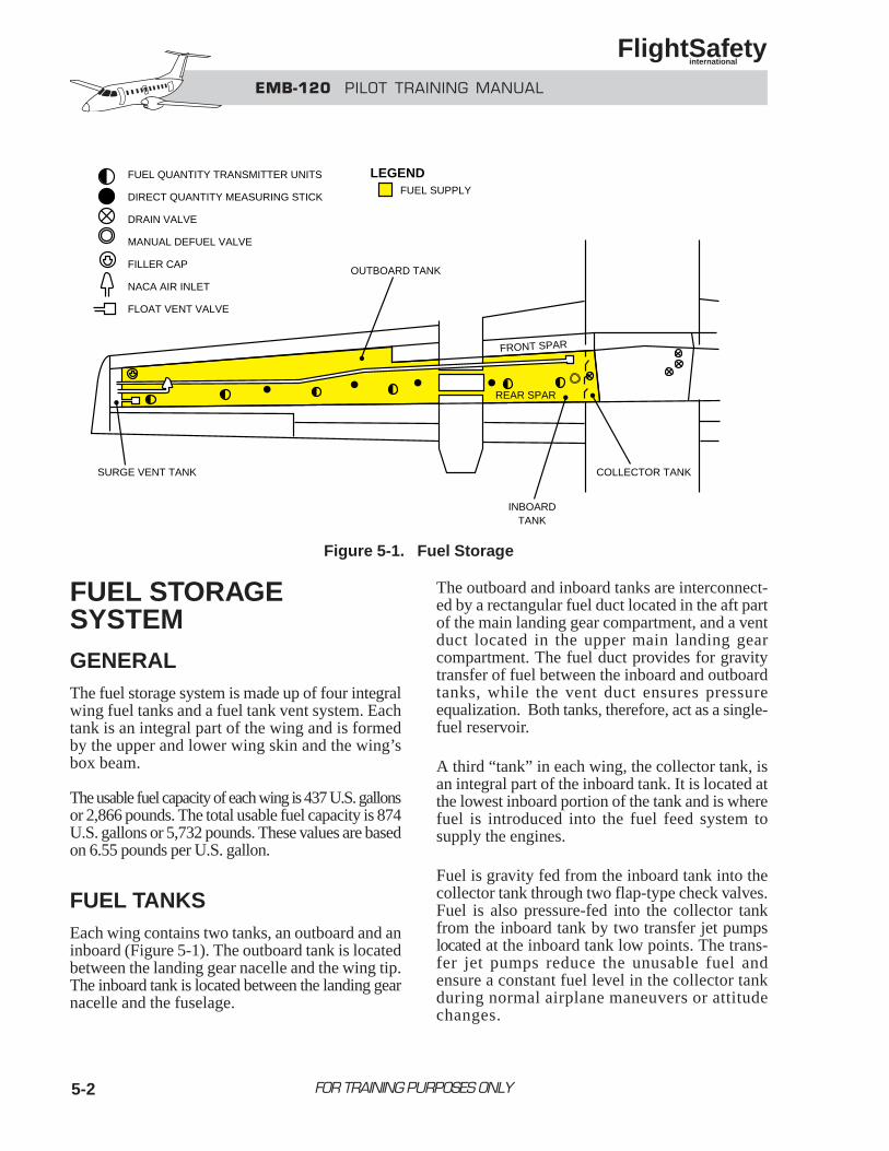
5-2
FUEL STORAGE SYSTEMGENERALThe fuel storage system is made up of four integralwing fuel tanks and a fuel tank vent system. Eachtank is an integral part of the wing and is formedby the upper and lower wing skin and the wing’sbox beam.
The usable fuel capacity of each wing is 437 U.S. gallonsor 2,866 pounds. The total usable fuel capacity is 874U.S. gallons or 5,732 pounds. These values are basedon 6.55 pounds per U.S. gallon.
FUEL TANKSEach wing contains two tanks, an outboard and aninboard (Figure 5-1). The outboard tank is locatedbetween the landing gear nacelle and the wing tip.The inboard tank is located between the landing gearnacelle and the fuselage.
The outboard and inboard tanks are interconnect-ed by a rectangular fuel duct located in the aft partof the main landing gear compartment, and a ventduct located in the upper main landing gearcompartment. The fuel duct provides for gravitytransfer of fuel between the inboard and outboardtanks, while the vent duct ensures pressureequalization. Both tanks, therefore, act as a single-fuel reservoir.
A third “tank” in each wing, the collector tank, isan integral part of the inboard tank. It is located atthe lowest inboard portion of the tank and is wherefuel is introduced into the fuel feed system tosupply the engines.
Fuel is gravity fed from the inboard tank into thecollector tank through two flap-type check valves.Fuel is also pressure-fed into the collector tankfrom the inboard tank by two transfer jet pumpslocated at the inboard tank low points. The trans-fer jet pumps reduce the unusable fuel andensure a constant fuel level in the collector tankduring normal airplane maneuvers or attitudechanges.
FOR TRAINING PURPOSES ONLY
EMB-120 PILOT TRAINING MANUAL
FlightSafety international
FUEL SUPPLY
FUEL QUANTITY TRANSMITTER UNITS
DIRECT QUANTITY MEASURING STICK
DRAIN VALVE
MANUAL DEFUEL VALVE
FILLER CAP
NACA AIR INLET
FLOAT VENT VALVE
OUTBOARD TANK
SURGE VENT TANK
INBOARDTANK
COLLECTOR TANK
FRONT SPAR
REAR SPAR
LEGEND
Figure 5-1. Fuel Storage
5-3
A constant fuel level is necessary because, aspreviously mentioned, the collector tank is thepoint from which fuel is fed to the engine.
The electric booster pumps and the main jet pumpfor the fuel feed system are mounted in the collectortank, and a drain valve is located at its lowest point.
FUEL TANK VENTING The fuel tank vent system provides a means toequalize pressure differentials between thewing tanks and the atmosphere. These pressuredifferentials may be created by fuel pumpsuction, airplane altitude variation, or fuelexpansion due to temperature increase.
The fuel tank vent system is identical in both wingsand consists of the following components:
• Tank interconnecting vent duct
• Surge vent tank
• NACA air intake
• Flame arrestor
• Float vent valves
The vent duct interconnects the outboard andinboard tanks. This duct is located in the upper partof the landing gear compartment and intercon-nects the upper part of both tanks to insure pressureequalization and vent system efficiency.
The surge vent tank is located at the wing tipend of the outboard tank (Figure 5-1), andprovides the means for eliminating internal andexternal pressure differentials.
The NACA air intake (Figure 5-1) connects the surgevent tank with the atmosphere. Located on theunderside of the wing, it is mounted along with asedimentation tank in such a way that, in case of rain,water is separated and drained overboard.
The flame arrestor allows air/fuel vapors to vent tothe atmosphere but prevents external flames frompropagating through the vent system tubing into thefuel tanks. It is located in the vent tube between theNACA air inlet and the surge vent tank.
A float vent valve, located at the highest point in eachof the tanks (Figure 5-1), prevents fuel from flowingfrom the fuel tank into the surge vent tank duringslips, skids or taxiing turns.
NOTEThe float vent valve is not the same as therefueling vent valve explained in therefueling/defueling section. The normaltank vent lines are not large enough toallow for a safe single-point refuelingoperation.
FUEL FEED SYSTEM
GENERALThe fuel feed system (Figure 5-2) is divided into twoidentical left and right subsystems which providefuel to the main engines and APU. The mainengines are normally fed by the fuel system intheir respective wing. The APU is normally fed fromthe fuel system in the right wing.
The fuel feed system in each wing consists of thefollowing components:
• Electric boost pumps
• Main jet pump
• Transfer jet pumps
• Check valves
• Firewall shutoff valve
• Crossfeed
• Motive flow shutoff valve
• Relief valve
FOR TRAINING PURPOSES ONLY
EMB-120 PILOT TRAINING MANUAL
FlightSafety international
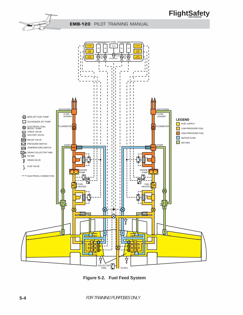
5-4 FOR TRAINING PURPOSES ONLY
EMB-120 PILOT TRAINING MANUAL
FlightSafety international
SHUTDOWN
FLOWDIVIDER
FLOWMETER
START
ENGINEPUMP
FUELHEATER
OPEN
OPEN
LEFT PUMPS RIGHT PUMPS
ON ON ON ON
CLOSEONAUTOFF
ONAUTOFF
FRONT REAR REAR FRONTCROSSFEED
FILTER
LOWTEMP
LOWPRESS
FILTER
LOWTEMP
LOWPRESS
FUEL
SHUTDOWN
FLOWDIVIDER
FLOWMETER
STARTHMU
ENGINEPUMP
FUELHEATER
COLLECTORTANK TO APU
MAIN JET FUEL PUMP
SCAVENGER JET PUMP
ELECTRICAL FUELBOOST PUMP
CHECK VALVE
SHUTOFF VALVE
RELIEF VALVE
PRESSURE SWITCH
TEMPERATURE SWITCH
DRAIN COLLECTOR TANK
FILTER
DRAIN VALVE
FLAP VALVE
ELECTRICAL CONNECTION
FUEL SUPPLY
LOW-PRESSURE FUEL
HIGH-PRESSURE FUEL
MOTIVE FLOW
RETURN
LEGEND
HMU
Figure 5-2. Fuel Feed System
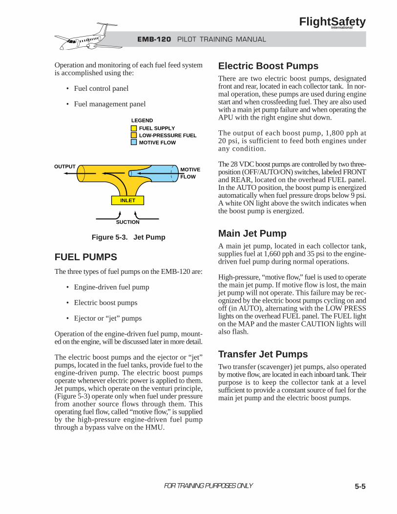
5-5
Operation and monitoring of each fuel feed systemis accomplished using the:
• Fuel control panel
• Fuel management panel
FUEL PUMPSThe three types of fuel pumps on the EMB-120 are:
• Engine-driven fuel pump
• Electric boost pumps
• Ejector or “jet” pumps
Operation of the engine-driven fuel pump, mount-ed on the engine, will be discussed later in more detail.
The electric boost pumps and the ejector or “jet”pumps, located in the fuel tanks, provide fuel to theengine-driven pump. The electric boost pumpsoperate whenever electric power is applied to them.Jet pumps, which operate on the venturi principle,(Figure 5-3) operate only when fuel under pressurefrom another source flows through them. Thisoperating fuel flow, called “motive flow,” is suppliedby the high-pressure engine-driven fuel pumpthrough a bypass valve on the HMU.
Electric Boost PumpsThere are two electric boost pumps, designatedfront and rear, located in each collector tank. In nor-mal operation, these pumps are used during enginestart and when crossfeeding fuel. They are also usedwith a main jet pump failure and when operating theAPU with the right engine shut down.
The output of each boost pump, 1,800 pph at20 psi, is sufficient to feed both engines underany condition.
The 28 VDC boost pumps are controlled by two three-position (OFF/AUTO/ON) switches, labeled FRONTand REAR, located on the overhead FUEL panel.In the AUTO position, the boost pump is energizedautomatically when fuel pressure drops below 9 psi.A white ON light above the switch indicates whenthe boost pump is energized.
Main Jet PumpA main jet pump, located in each collector tank,supplies fuel at 1,660 pph and 35 psi to the engine-driven fuel pump during normal operations.
High-pressure, “motive flow,” fuel is used to operatethe main jet pump. If motive flow is lost, the mainjet pump will not operate. This failure may be rec-ognized by the electric boost pumps cycling on andoff (in AUTO), alternating with the LOW PRESSlights on the overhead FUEL panel. The FUEL lighton the MAP and the master CAUTION lights willalso flash.
Transfer Jet PumpsTwo transfer (scavenger) jet pumps, also operatedby motive flow, are located in each inboard tank. Theirpurpose is to keep the collector tank at a levelsufficient to provide a constant source of fuel for themain jet pump and the electric boost pumps.
FOR TRAINING PURPOSES ONLY
EMB-120 PILOT TRAINING MANUAL
FlightSafety international
INLET
SUCTION
OUTPUT MOTIVEFLOW
FUEL SUPPLYLOW-PRESSURE FUELMOTIVE FLOW
LEGEND
Figure 5-3. Jet Pump
5-6
When operating, the transfer jet pumps increase theusable fuel by taking fuel from the lowestportions of the inboard tank and transferring itinto the collector tank. When the transfer jet pumpsare not operating, usable fuel in the correspondingwing tank is reduced by 79.6 lb (12.15 US gallons).
If motive flow is lost, the transfer jet pumps will notoperate. There is no failure annunciation for the trans-fer jet pumps. However, with the loss of motive flow,the main jet pump no longer operates either and thefailure is recognized by the LOW PRESS indicationspreviously discussed.
FUEL SYSTEM VALVES
Fuel Pump Check ValvesThese check valves are designed to prevent thereturn of fuel from the supply lines to the collectortank through an inoperative pump. The valves areplaced in the fuel lines at the outlets of each elec-tric boost pump and main jet pump.
Firewall Shutoff ValveThe firewall shutoff-valve is an electrically actuatedgate valve that provides a means to stop the flow offuel to the engine.
During normal operation, the valve is in the openposition allowing fuel to flow from the tanks tothe HMU.
The valve closes when the respective engine FIREHANDLE is pulled. A white fuel CLOSED light onthe glareshield fire protection panel illuminateswhen the shutoff valve is closed.
Crossfeed ValveThe crossfeed shutoff valve is located in the cross-feed manifold that connects the right and left fuelsystems. This crossfeed system enables the enginesand the APU to receive fuel from either or both wings.
The crossfeed valve is physically and functionallyidentical to the firewall shutoff valves. It controlsthe flow of fuel through the crossfeed manifold. Dur-ing normal operation this valve is closed.
The valve, powered by emergency DC bus 1, is con-trolled by the CROSSFEED switch on the overheadfuel control panel. When the crossfeed valve opens,both a white light above the switch (labeled OPEN)and a white light on the fuel quantity indication panel(labeled CROSS FEED OPEN) illuminate.
When the crossfeed valve is opened, both motive flowshutoff valves close. Therefore, during crossfeedoperations, an electric boost pump must be used.Also, because motive flow is lost and the transfer jetpumps no longer operate, the unusable fuel is increasedby 79.6 lbs (12.15 U.S. gallons) in each tank.
Motive Flow Shutoff ValveThe motive flow shutoff valves control the fuel flowfrom the HMU to the jet pumps. They are ball-type,electrically actuated valves and operate in con-junction with the crossfeed valve.
These valves are normally in the open position. Whenthe crossfeed switch is placed in the OPEN position,the motive flow shutoff valves close, blocking fuelflow to the main and transfer jet pumps.
A check valve is located at the outlet of eachmotive flow shutoff valve to prevent reversefuel flow into the engine compartment if a fuelline should rupture.
Relief ValveEach fuel line is equipped with a pressure relief valve.The relief valve will divert fuel from the fuel lineto the inboard tank when fuel line pressure exceeds50 psi.
FOR TRAINING PURPOSES ONLY
EMB-120 PILOT TRAINING MANUAL
FlightSafety international
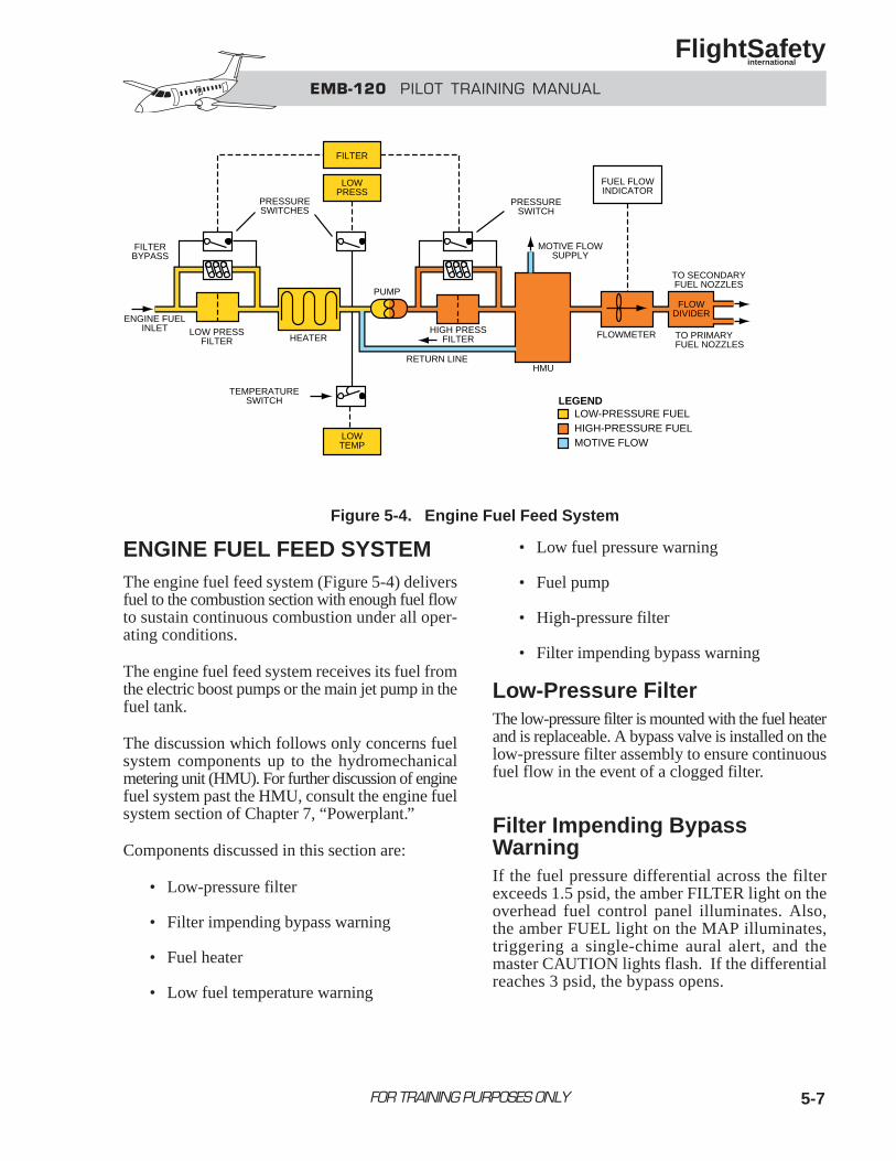
5-7
ENGINE FUEL FEED SYSTEMThe engine fuel feed system (Figure 5-4) deliversfuel to the combustion section with enough fuel flowto sustain continuous combustion under all oper-ating conditions.
The engine fuel feed system receives its fuel fromthe electric boost pumps or the main jet pump in thefuel tank.
The discussion which follows only concerns fuelsystem components up to the hydromechanicalmetering unit (HMU). For further discussion of enginefuel system past the HMU, consult the engine fuelsystem section of Chapter 7, “Powerplant.”
Components discussed in this section are:
• Low-pressure filter
• Filter impending bypass warning
• Fuel heater
• Low fuel temperature warning
• Low fuel pressure warning
• Fuel pump
• High-pressure filter
• Filter impending bypass warning
Low-Pressure FilterThe low-pressure filter is mounted with the fuel heaterand is replaceable. A bypass valve is installed on thelow-pressure filter assembly to ensure continuousfuel flow in the event of a clogged filter.
Filter Impending Bypass WarningIf the fuel pressure differential across the filterexceeds 1.5 psid, the amber FILTER light on theoverhead fuel control panel illuminates. Also,the amber FUEL light on the MAP illuminates,triggering a single-chime aural alert, and themaster CAUTION lights flash. If the differentialreaches 3 psid, the bypass opens.
FOR TRAINING PURPOSES ONLY
EMB-120 PILOT TRAINING MANUAL
FlightSafety international
FILTER
LOWPRESS
PRESSURESWITCHES
FILTERBYPASS
ENGINE FUELINLET LOW PRESS
FILTER HEATER
LOWTEMP
HIGH PRESSFILTER
PUMP
RETURN LINEHMU
MOTIVE FLOWSUPPLY
FUEL FLOWINDICATOR
PRESSURESWITCH
TO SECONDARYFUEL NOZZLES
FLOWDIVIDER
TO PRIMARYFUEL NOZZLES
FLOWMETER
TEMPERATURESWITCH
LOW-PRESSURE FUELHIGH-PRESSURE FUELMOTIVE FLOW
LEGEND
Figure 5-4. Engine Fuel Feed System
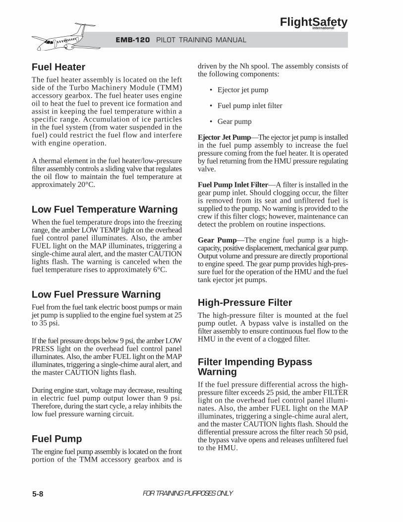
5-8
Fuel HeaterThe fuel heater assembly is located on the leftside of the Turbo Machinery Module (TMM)accessory gearbox. The fuel heater uses engineoil to heat the fuel to prevent ice formation andassist in keeping the fuel temperature within aspecific range. Accumulation of ice particlesin the fuel system (from water suspended in thefuel) could restrict the fuel flow and interferewith engine operation.
A thermal element in the fuel heater/low-pressurefilter assembly controls a sliding valve that regulatesthe oil flow to maintain the fuel temperature atapproximately 20°C.
Low Fuel Temperature WarningWhen the fuel temperature drops into the freezingrange, the amber LOW TEMP light on the overheadfuel control panel illuminates. Also, the amberFUEL light on the MAP illuminates, triggering asingle-chime aural alert, and the master CAUTIONlights flash. The warning is canceled when thefuel temperature rises to approximately 6°C.
Low Fuel Pressure WarningFuel from the fuel tank electric boost pumps or mainjet pump is supplied to the engine fuel system at 25to 35 psi.
If the fuel pressure drops below 9 psi, the amber LOWPRESS light on the overhead fuel control panelilluminates. Also, the amber FUEL light on the MAPilluminates, triggering a single-chime aural alert, andthe master CAUTION lights flash.
During engine start, voltage may decrease, resultingin electric fuel pump output lower than 9 psi.Therefore, during the start cycle, a relay inhibits thelow fuel pressure warning circuit.
Fuel PumpThe engine fuel pump assembly is located on the frontportion of the TMM accessory gearbox and is
driven by the Nh spool. The assembly consists ofthe following components:
• Ejector jet pump
• Fuel pump inlet filter
• Gear pump
Ejector Jet Pump—The ejector jet pump is installedin the fuel pump assembly to increase the fuelpressure coming from the fuel heater. It is operatedby fuel returning from the HMU pressure regulatingvalve.
Fuel Pump Inlet Filter—A filter is installed in thegear pump inlet. Should clogging occur, the filteris removed from its seat and unfiltered fuel issupplied to the pump. No warning is provided to thecrew if this filter clogs; however, maintenance candetect the problem on routine inspections.
Gear Pump—The engine fuel pump is a high-capacity, positive displacement, mechanical gear pump.Output volume and pressure are directly proportionalto engine speed. The gear pump provides high-pres-sure fuel for the operation of the HMU and the fueltank ejector jet pumps.
High-Pressure FilterThe high-pressure filter is mounted at the fuelpump outlet. A bypass valve is installed on thefilter assembly to ensure continuous fuel flow to theHMU in the event of a clogged filter.
Filter Impending Bypass WarningIf the fuel pressure differential across the high-pressure filter exceeds 25 psid, the amber FILTERlight on the overhead fuel control panel illumi-nates. Also, the amber FUEL light on the MAPilluminates, triggering a single-chime aural alert,and the master CAUTION lights flash. Should thedifferential pressure across the filter reach 50 psid,the bypass valve opens and releases unfiltered fuelto the HMU.
FOR TRAINING PURPOSES ONLY
EMB-120 PILOT TRAINING MANUAL
FlightSafety international
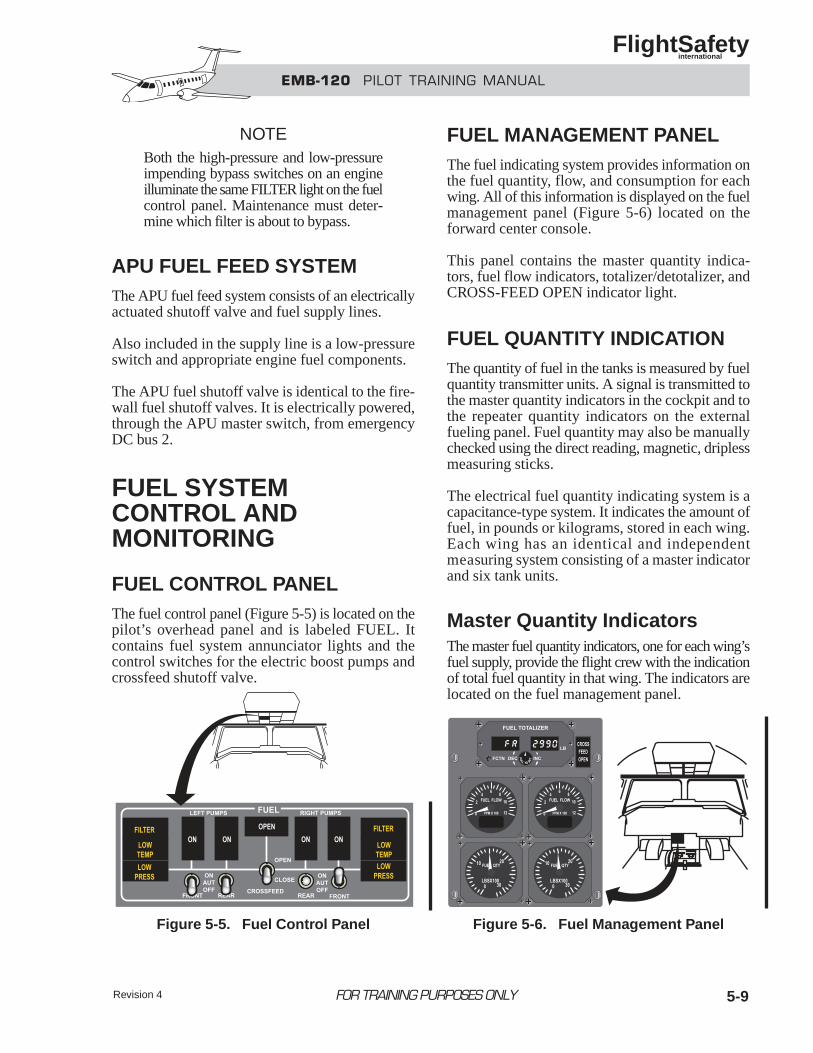
Revision 4 5-9
NOTEBoth the high-pressure and low-pressureimpending bypass switches on an engineilluminate the same FILTER light on the fuelcontrol panel. Maintenance must deter-mine which filter is about to bypass.
APU FUEL FEED SYSTEMThe APU fuel feed system consists of an electricallyactuated shutoff valve and fuel supply lines.
Also included in the supply line is a low-pressureswitch and appropriate engine fuel components.
The APU fuel shutoff valve is identical to the fire-wall fuel shutoff valves. It is electrically powered,through the APU master switch, from emergencyDC bus 2.
FUEL SYSTEM CONTROL AND MONITORING
FUEL CONTROL PANELThe fuel control panel (Figure 5-5) is located on thepilot’s overhead panel and is labeled FUEL. Itcontains fuel system annunciator lights and thecontrol switches for the electric boost pumps andcrossfeed shutoff valve.
FUEL MANAGEMENT PANELThe fuel indicating system provides information onthe fuel quantity, flow, and consumption for eachwing. All of this information is displayed on the fuelmanagement panel (Figure 5-6) located on theforward center console.
This panel contains the master quantity indica-tors, fuel flow indicators, totalizer/detotalizer, andCROSS-FEED OPEN indicator light.
FUEL QUANTITY INDICATIONThe quantity of fuel in the tanks is measured by fuelquantity transmitter units. A signal is transmitted tothe master quantity indicators in the cockpit and tothe repeater quantity indicators on the externalfueling panel. Fuel quantity may also be manuallychecked using the direct reading, magnetic, driplessmeasuring sticks.
The electrical fuel quantity indicating system is acapacitance-type system. It indicates the amount offuel, in pounds or kilograms, stored in each wing.Each wing has an identical and independentmeasuring system consisting of a master indicatorand six tank units.
Master Quantity IndicatorsThe master fuel quantity indicators, one for each wing’sfuel supply, provide the flight crew with the indicationof total fuel quantity in that wing. The indicators arelocated on the fuel management panel.
FOR TRAINING PURPOSES ONLY
EMB-120 PILOT TRAINING MANUAL
FlightSafety international
Figure 5-5. Fuel Control Panel Figure 5-6. Fuel Management Panel
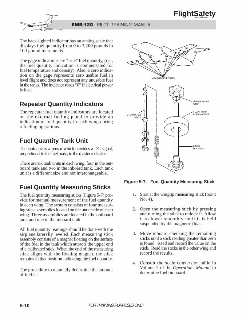
5-10
The back-lighted indicator has an analog scale thatdisplays fuel quantity from 0 to 3,200 pounds in100 pound increments.
The gage indications are “true” fuel quantity, (i.e.,the fuel quantity indication is compensated forfuel temperature and density). Also, a zero indica-tion on the gage represents zero usable fuel inlevel flight and does not represent any unusable fuelin the tanks. The indicator reads “0” if electrical poweris lost.
Repeater Quantity IndicatorsThe repeater fuel quantity indicators are locatedon the external fueling panel to provide anindication of fuel quantity in each wing duringrefueling operations.
Fuel Quantity Tank UnitThe tank unit is a sensor which provides a DC signal,proportional to the fuel mass, to the master indicator.
There are six tank units in each wing, four in the out-board tank and two in the inboard tank. Each tankunit is a different size and not interchangeable.
Fuel Quantity Measuring SticksThe fuel quantity measuring sticks (Figure 5-7) pro-vide for manual measurement of the fuel quantityin each wing. The system consists of four measur-ing stick assemblies located on the underside of eachwing. Three assemblies are located in the outboardtank and one in the inboard tank.
All fuel quantity readings should be done with theairplane laterally leveled. Each measuring stickassembly consists of a magnet floating on the surfaceof the fuel in the tank which attracts the upper endof a calibrated stick. When the end of the measuringstick aligns with the floating magnet, the stickremains in that position indicating the fuel quantity.
The procedure to manually determine the amountof fuel is:
1. Start at the wingtip measuring stick (pointNo. 4).
2. Open the measuring stick by pressingand turning the stick to unlock it. Allowit to lower smoothly until it is heldsuspended by the magnetic float.
3. Move inboard checking the remainingsticks until a stick reading greater than zerois found. Read and record the value on thestick. Read the sticks in the other wing andrecord the results.
4. Consult the scale conversion table inVolume 2 of the Operations Manual todetermine fuel on board.
FOR TRAINING PURPOSES ONLY
EMB-120 PILOT TRAINING MANUAL
FlightSafety international
4 3 21
1
23
4
MEASURING POINTS
UPPER FLOATSTOP
FLOAT WITHRING MAGNET
STICKHOUSING
GRATUATEDSTICK
Figure 5-7. Fuel Quantity Measuring Stick
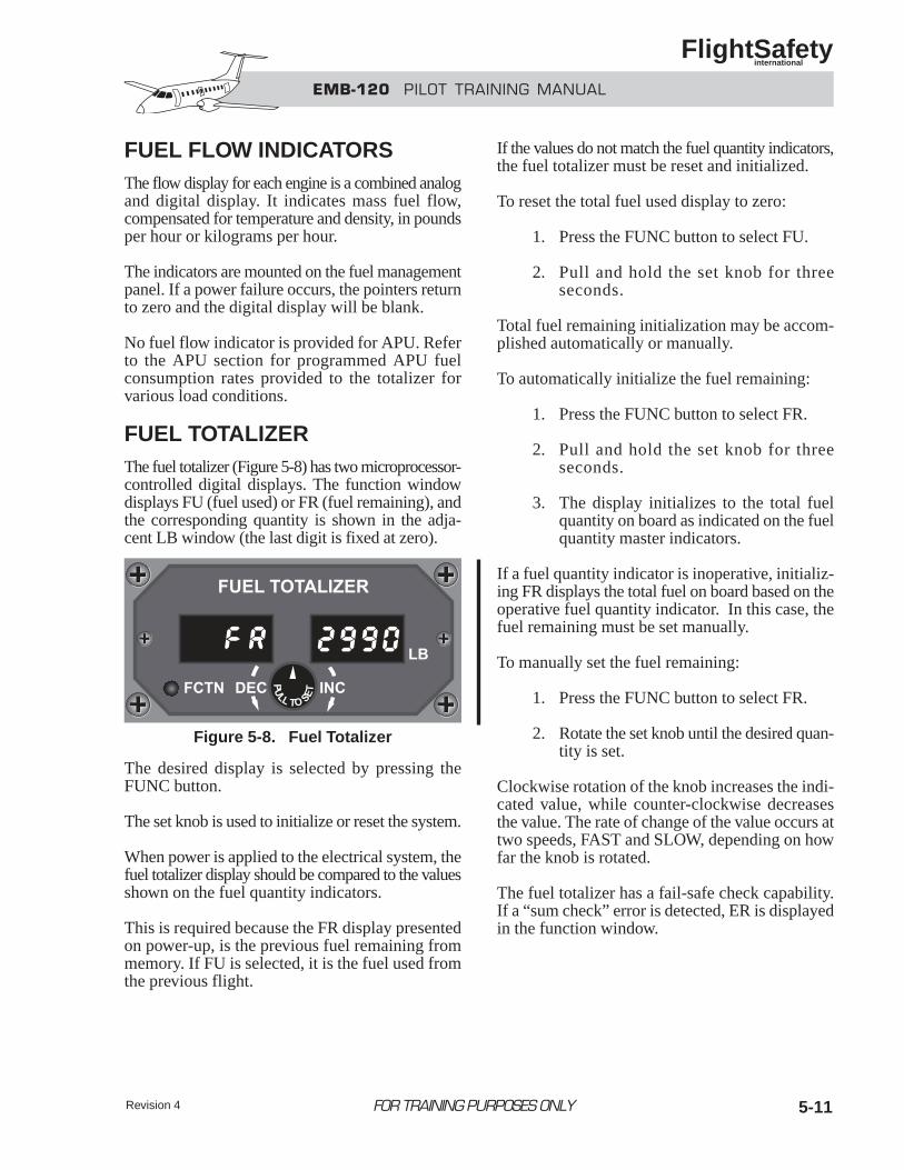
Revision 4 5-11
FUEL FLOW INDICATORSThe flow display for each engine is a combined analogand digital display. It indicates mass fuel flow,compensated for temperature and density, in poundsper hour or kilograms per hour.
The indicators are mounted on the fuel managementpanel. If a power failure occurs, the pointers returnto zero and the digital display will be blank.
No fuel flow indicator is provided for APU. Referto the APU section for programmed APU fuelconsumption rates provided to the totalizer forvarious load conditions.
FUEL TOTALIZERThe fuel totalizer (Figure 5-8) has two microprocessor-controlled digital displays. The function windowdisplays FU (fuel used) or FR (fuel remaining), andthe corresponding quantity is shown in the adja-cent LB window (the last digit is fixed at zero).
The desired display is selected by pressing theFUNC button.
The set knob is used to initialize or reset the system.
When power is applied to the electrical system, thefuel totalizer display should be compared to the valuesshown on the fuel quantity indicators.
This is required because the FR display presentedon power-up, is the previous fuel remaining frommemory. If FU is selected, it is the fuel used fromthe previous flight.
If the values do not match the fuel quantity indicators,the fuel totalizer must be reset and initialized.
To reset the total fuel used display to zero:
1. Press the FUNC button to select FU.
2. Pull and hold the set knob for threeseconds.
Total fuel remaining initialization may be accom-plished automatically or manually.
To automatically initialize the fuel remaining:
1. Press the FUNC button to select FR.
2. Pull and hold the set knob for threeseconds.
3. The display initializes to the total fuelquantity on board as indicated on the fuelquantity master indicators.
If a fuel quantity indicator is inoperative, initializ-ing FR displays the total fuel on board based on theoperative fuel quantity indicator. In this case, thefuel remaining must be set manually.
To manually set the fuel remaining:
1. Press the FUNC button to select FR.
2. Rotate the set knob until the desired quan-tity is set.
Clockwise rotation of the knob increases the indi-cated value, while counter-clockwise decreasesthe value. The rate of change of the value occurs attwo speeds, FAST and SLOW, depending on howfar the knob is rotated.
The fuel totalizer has a fail-safe check capability.If a “sum check” error is detected, ER is displayedin the function window.
FOR TRAINING PURPOSES ONLY
EMB-120 PILOT TRAINING MANUAL
FlightSafety international
Figure 5-8. Fuel Totalizer
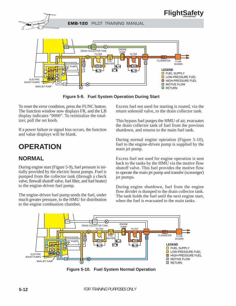
5-12
To reset the error condition, press the FUNC button.The function window now displays FR, and the LBdisplay indicates “0000”. To reinitialize the total-izer, pull the set knob.
If a power failure or signal loss occurs, the functionand value displays will be blank.
OPERATION
NORMALDuring engine start (Figure 5-9), fuel pressure is ini-tially provided by the electric boost pumps. Fuel ispumped from the collector tank (through a checkvalve, firewall shutoff valve, fuel filter, and fuel heater)to the engine-driven fuel pump.
The engine-driven fuel pump sends the fuel, undermuch greater pressure, to the HMU for distributionto the engine combustion chamber.
Excess fuel not used for starting is routed, via thereturn solenoid valve, to the drain collector tank.
This bypass fuel purges the HMU of air, evacuatesthe drain collector tank of fuel from the previousshutdown, and returns to the main fuel tank.
During normal engine operation (Figure 5-10),fuel to the engine-driven pump is supplied by themain jet pump.
Excess fuel not used for engine operation is sentback to the tanks by the HMU via the motive flowshutoff valve. This fuel provides the motive flowto operate the main jet pump and transfer (scavenger)jet pumps.
During engine shutdown, fuel from the engineflow divider is dumped to the drain collector tank.The tank holds the fuel until the next engine start,when the fuel is evacuated to the main tanks.
FOR TRAINING PURPOSES ONLY
EMB-120 PILOT TRAINING MANUAL
FlightSafety international
MAIN JET PUMP
FLOWMETER FLOWDIVIDER
FILTERFILTER
ENGINEPUMP
FUELHEATER
DRAIN COLLECTOR TANK
ELECTRICBOOST PUMPS
FUEL SUPPLYLOW-PRESSURE FUELHIGH-PRESSURE FUELMOTIVE FLOWRETURN
HMU
SCAVENGERJET PUMPS
LEGEND
Figure 5-9. Fuel System Operation During Start
MAIN JET PUMP
FLOWMETER FLOWDIVIDER
FILTERFILTER
ENGINEPUMP
FUELHEATER
DRAIN COLLECTOR TANK
ELECTRICBOOST PUMPS
HMU
SCAVENGERJET PUMPS
FUEL SUPPLYLOW-PRESSURE FUELHIGH-PRESSURE FUELMOTIVE FLOWRETURN
LEGEND
Figure 5-10. Fuel System Normal Operation
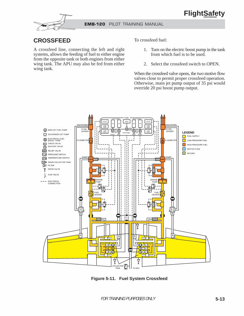
5-13
CROSSFEEDA crossfeed line, connecting the left and rightsystems, allows the feeding of fuel to either enginefrom the opposite tank or both engines from eitherwing tank. The APU may also be fed from eitherwing tank.
To crossfeed fuel:
1. Turn on the electric boost pump in the tankfrom which fuel is to be used.
2. Select the crossfeed switch to OPEN.
When the crossfeed valve opens, the two motive flowvalves close to permit proper crossfeed operation.Otherwise, main jet pump output of 35 psi wouldoverride 20 psi boost pump output.
FOR TRAINING PURPOSES ONLY
EMB-120 PILOT TRAINING MANUAL
FlightSafety international
SHUTDOWN
FLOWDIVIDER
FLOWMETER
STARTHMU
ENGINEPUMP
FUELHEATER
OPEN
OPEN
LEFT PUMPS RIGHT PUMPS
ON ON ON ON
CLOSEONAUTOFF
ONAUTOFF
FRONT REAR REAR FRONTCROSSFEED
FILTER
LOWTEMP
LOWPRESS
FILTER
LOWTEMP
LOWPRESS
FUEL
SHUTDOWN
FLOWDIVIDER
FLOWMETER
STARTHMU
ENGINEPUMP
FUELHEATER
COLLECTORTANK TO APU
MAIN JET FUEL PUMP
SCAVENGER JET PUMP
ELECTRICAL FUELBOOST PUMP
CHECK VALVE
SHUTOFF VALVE
RELIEF VALVE
PRESSURE SWITCH
TEMPERATURE SWITCH
DRAIN COLLECTOR TANK
FILTER
DRAIN VALVE
FLAP VALVE
ELECTRICALCONNECTION
FUEL SUPPLY
LOW-PRESSURE FUEL
HIGH-PRESSURE FUEL
MOTIVE FLOW
RETURN
LEGEND
Figure 5-11. Fuel System Crossfeed
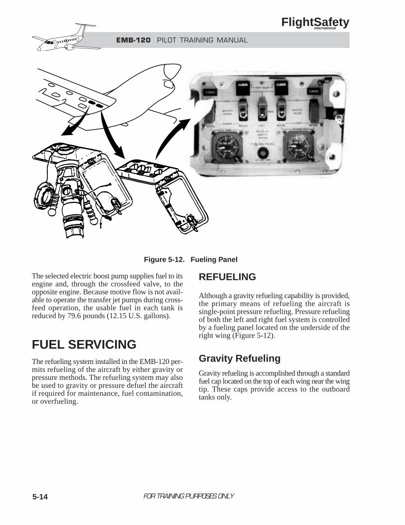
5-14
The selected electric boost pump supplies fuel to itsengine and, through the crossfeed valve, to theopposite engine. Because motive flow is not avail-able to operate the transfer jet pumps during cross-feed operation, the usable fuel in each tank isreduced by 79.6 pounds (12.15 U.S. gallons).
FUEL SERVICINGThe refueling system installed in the EMB-120 per-mits refueling of the aircraft by either gravity orpressure methods. The refueling system may alsobe used to gravity or pressure defuel the aircraftif required for maintenance, fuel contamination,or overfueling.
REFUELING
Although a gravity refueling capability is provided,the primary means of refueling the aircraft issingle-point pressure refueling. Pressure refuelingof both the left and right fuel system is controlledby a fueling panel located on the underside of theright wing (Figure 5-12).
Gravity Refueling Gravity refueling is accomplished through a standardfuel cap located on the top of each wing near the wingtip. These caps provide access to the outboardtanks only.
FOR TRAINING PURPOSES ONLY
EMB-120 PILOT TRAINING MANUAL
FlightSafety international
Figure 5-12. Fueling Panel
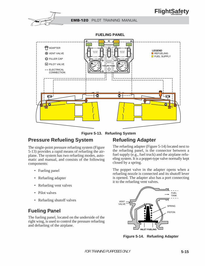
5-15
Pressure Refueling SystemThe single-point pressure refueling system (Figure5-13) provides a rapid means of refueling the air-plane. The system has two refueling modes, auto-matic and manual, and consists of the followingcomponents:
• Fueling panel
• Refueling adapter
• Refueling vent valves
• Pilot valves
• Refueling shutoff valves
Fueling PanelThe fueling panel, located on the underside of theright wing, is used to control the pressure refuelingand defueling of the airplane.
Refueling AdapterThe refueling adapter (Figure 5-14) located next tothe refueling panel, is the connector between afuel supply (e.g., fuel truck) and the airplane refu-eling system. It is a poppet-type valve normally keptclosed by a spring.
The poppet valve in the adapter opens when arefueling nozzle is connected and its shutoff leveris opened. The adapter also has a port connectingit to the refueling vent valves.
FOR TRAINING PURPOSES ONLY
EMB-120 PILOT TRAINING MANUAL
FlightSafety international
VENT VALVECLOSED
CLOSED
CLOSED
CLOSED CLOSEDCLOSED
CLOSED CLOSED
AUTO
OPEN OPEN
SHUTOFFVALVES
SHUTOFFVALVES
DEFUEL REFUEL DEFUELREFUELOFFL TANK R TANK
0
5
1015
20
25
30
FUEL QTY
0
5
1015
20
25
30
FUEL QTY
REFUELINGFUEL SUPPLY
ADAPTER
VENT VALVE
FILLER CAP
PILOT VALVE
ELECTRICALCONNECTION
FUELING PANEL
LEGENDMAN
FUELING PANEL
REFUELINGMASTERSWITCH
QTY IND TEST
Figure 5-13. Refueling System
FUELTANK
VENTVALVE
INLET FUELING
SPRING
PISTON
Figure 5-14. Refueling Adapter
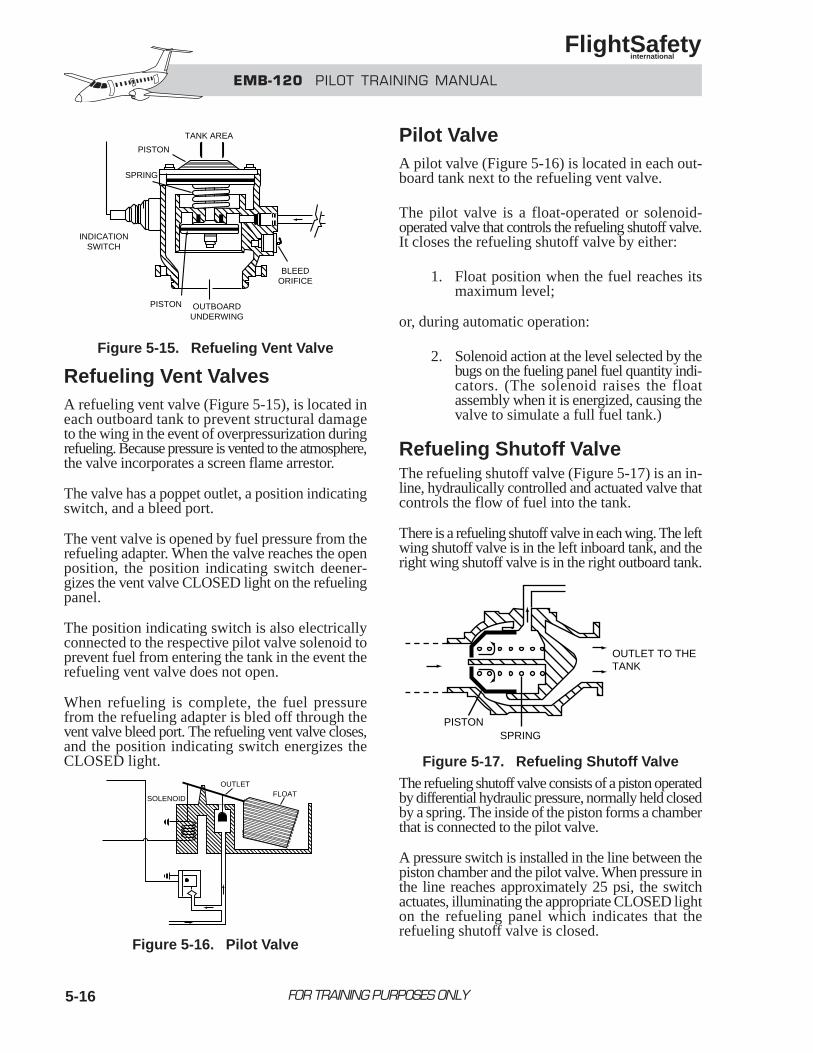
EMB-120 PILOT TRAINING MANUAL
FlightSafety international
FOR TRAINING PURPOSES ONLY5-16
Refueling Vent ValvesA refueling vent valve (Figure 5-15), is located ineach outboard tank to prevent structural damageto the wing in the event of overpressurization duringrefueling. Because pressure is vented to the atmosphere,the valve incorporates a screen flame arrestor.
The valve has a poppet outlet, a position indicatingswitch, and a bleed port.
The vent valve is opened by fuel pressure from therefueling adapter. When the valve reaches the openposition, the position indicating switch deener-gizes the vent valve CLOSED light on the refuelingpanel.
The position indicating switch is also electricallyconnected to the respective pilot valve solenoid toprevent fuel from entering the tank in the event therefueling vent valve does not open.
When refueling is complete, the fuel pressurefrom the refueling adapter is bled off through thevent valve bleed port. The refueling vent valve closes,and the position indicating switch energizes theCLOSED light.
Pilot ValveA pilot valve (Figure 5-16) is located in each out-board tank next to the refueling vent valve.
The pilot valve is a float-operated or solenoid-operated valve that controls the refueling shutoff valve.It closes the refueling shutoff valve by either:
1. Float position when the fuel reaches itsmaximum level;
or, during automatic operation:
2. Solenoid action at the level selected by thebugs on the fueling panel fuel quantity indi-cators. (The solenoid raises the floatassembly when it is energized, causing thevalve to simulate a full fuel tank.)
Refueling Shutoff ValveThe refueling shutoff valve (Figure 5-17) is an in-line, hydraulically controlled and actuated valve thatcontrols the flow of fuel into the tank.
There is a refueling shutoff valve in each wing. The leftwing shutoff valve is in the left inboard tank, and theright wing shutoff valve is in the right outboard tank.
The refueling shutoff valve consists of a piston operatedby differential hydraulic pressure, normally held closedby a spring. The inside of the piston forms a chamberthat is connected to the pilot valve.
A pressure switch is installed in the line between thepiston chamber and the pilot valve. When pressure inthe line reaches approximately 25 psi, the switchactuates, illuminating the appropriate CLOSED lighton the refueling panel which indicates that therefueling shutoff valve is closed.
OUTLET TO THETANK
SPRINGPISTON
Figure 5-17. Refueling Shutoff Valve
TANK AREA
BLEEDORIFICE
PISTON
PISTON
SPRING
INDICATIONSWITCH
OUTBOARDUNDERWING
Figure 5-15. Refueling Vent Valve
OUTLET
FLOATSOLENOID
Figure 5-16. Pilot Valve
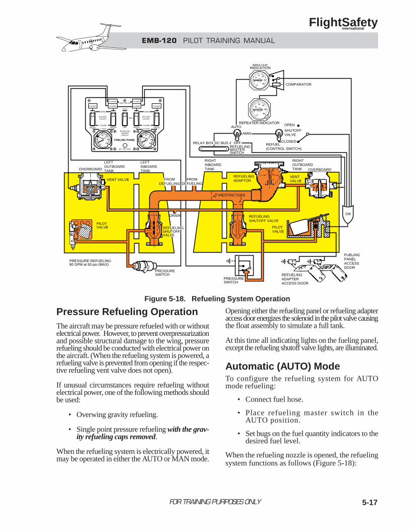
EMB-120 PILOT TRAINING MANUAL
FlightSafety international
FOR TRAINING PURPOSES ONLY
Pressure Refueling OperationThe aircraft may be pressure refueled with or withoutelectrical power. However, to prevent overpressurizationand possible structural damage to the wing, pressurerefueling should be conducted with electrical power onthe aircraft. (When the refueling system is powered, arefueling valve is prevented from opening if the respec-tive refueling vent valve does not open).
If unusual circumstances require refueling withoutelectrical power, one of the following methods shouldbe used:
• Overwing gravity refueling.
• Single point pressure refueling with the grav-ity refueling caps removed.
When the refueling system is electrically powered, itmay be operated in either the AUTO or MAN mode.
Opening either the refueling panel or refueling adapteraccess door energizes the solenoid in the pilot valve causingthe float assembly to simulate a full tank.
At this time all indicating lights on the fueling panel,except the refueling shutoff valve lights, are illuminated.
Automatic (AUTO) ModeTo configure the refueling system for AUTOmode refueling:
• Connect fuel hose.
• Place refueling master switch in theAUTO position.
• Set bugs on the fuel quantity indicators to thedesired fuel level.
When the refueling nozzle is opened, the refuelingsystem functions as follows (Figure 5-18):
5-17
0
5
1015
20
25
30
0
5
1015
20
25
30
OVERBOARD
LEFTOUTBOARDTANK
LEFTINBOARDTANK
RIGHTINBOARDTANK
RIGHTOUTBOARDTANK
VENT VALVE FROMDEFUELING
FROMDEFUELING
DRAIN
REFUELINGSHUTOFFVALVE
PRESSURESWITCH
PRESSURESWITCH
PILOTVALVE
PRESSURE REFUELING90 GPM at 50 psi (MAX)
RESTRICTORS
REFUELINGADAPTOR
VENTVALVE
OVERBOARD
ORREFUELINGSHUTOFF VALVE
PILOTVALVE
REFUELINGADAPTERACCESS DOOR
FUELINGPANELACCESSDOOR
SHUTOFFVALVE
REPEATER INDICATOR OPEN
CLOSEDREFUEL(CONTROL SWITCH)
MAN
RELAY BOX DC BUS 2 OFFREFUELINGMASTERSWITCH
AUTO
MASTERINDICATION
COMPARATOR
VENT VALVECLOSED
CLOSED
CLOSED
CLOSED CLOSEDCLOSED
CLOSED CLOSED
AUTO
OPEN OPEN
SHUTOFFVALVES
SHUTOFFVALVES
DEFUEL REFUEL DEFUELREFUELOFFL TANK R TANK
0
5
1015
20
25
30
FUEL QTY
0
5
1015
20
25
30
FUEL QTY
MAN
FUELING PANEL
REFUELINGMASTERSWITCH
QTY IND TEST
Figure 5-18. Refueling System Operation
5-18
1. Fuel pressure from the refueling adapteris transmitted to the refueling shutoffvalves, pilot valves, and refueling ventvalves. No fuel flows into the tanks atthis time.
2. In the shutoff valve, fuel pressure is trans-mitted through an orifice in the piston, tothe pilot valve through a connecting line.
3. In the pilot valve, the float is being held inthe “full” position by the solenoid, (ener-gized when the access doors were opened).
4. A back-pressure is created in the linebetween the shutoff valve and the pilot valve.
a. When this back-pressure reaches approx-imately 25 psi the pressure switchcloses, illuminating the shutoff valveCLOSED light on the fueling panel.
b. In the shutoff valve, this backpressureresults in a force on the rear of thepiston (larger area) greater than theforce on the face of the piston (smallerarea). This imbalance in forces, aidedby a spring, holds the piston in theclosed position.
5. Once the refueling vent valve is opened byfuel pressure from the refueling adapter,its position indicating switch deenergizesthe vent valve CLOSED light and thepilot valve solenoid.
6. When the pilot valve solenoid deener-gizes the float drops off of the “full” posi-tion and back-pressure in the pilot valvedissipates. As a result:
a. The shutoff valve CLOSED lightgoes out.
b. Fuel pressure overcomes spring pres-sure in the shutoff valve, displacingthe piston thus opening the valve.
7. Fuel flows into the tank until the fuelquantity indicators reach the preselected(bug) quantity or the tanks are full. Wheneither of these conditions are met, therefueling operation is automatically stopped.
Manual (MAN) ModeIn the manual mode the components of the refuelingsystem have the same function as in the automaticmode. The only difference is that the refuelingmaster switch is placed in the MAN position and therefueling shutoff valves have to be selected to theOPEN position.
In the MAN mode, the vent valve signal to the pilotvalve solenoid (holding the float in the “full”position) will not be deenergized until the shutoffvalve switch is placed to OPEN, regardless ofvent valve position.
During manual mode refueling, fuel flow stopswhen any of the following occurs:
• The tanks are full.
• The refueling shutoff valves are selected CLOSED.
• The refueling master switch is selected OFF.
FOR TRAINING PURPOSES ONLY
EMB-120 PILOT TRAINING MANUAL
FlightSafety international
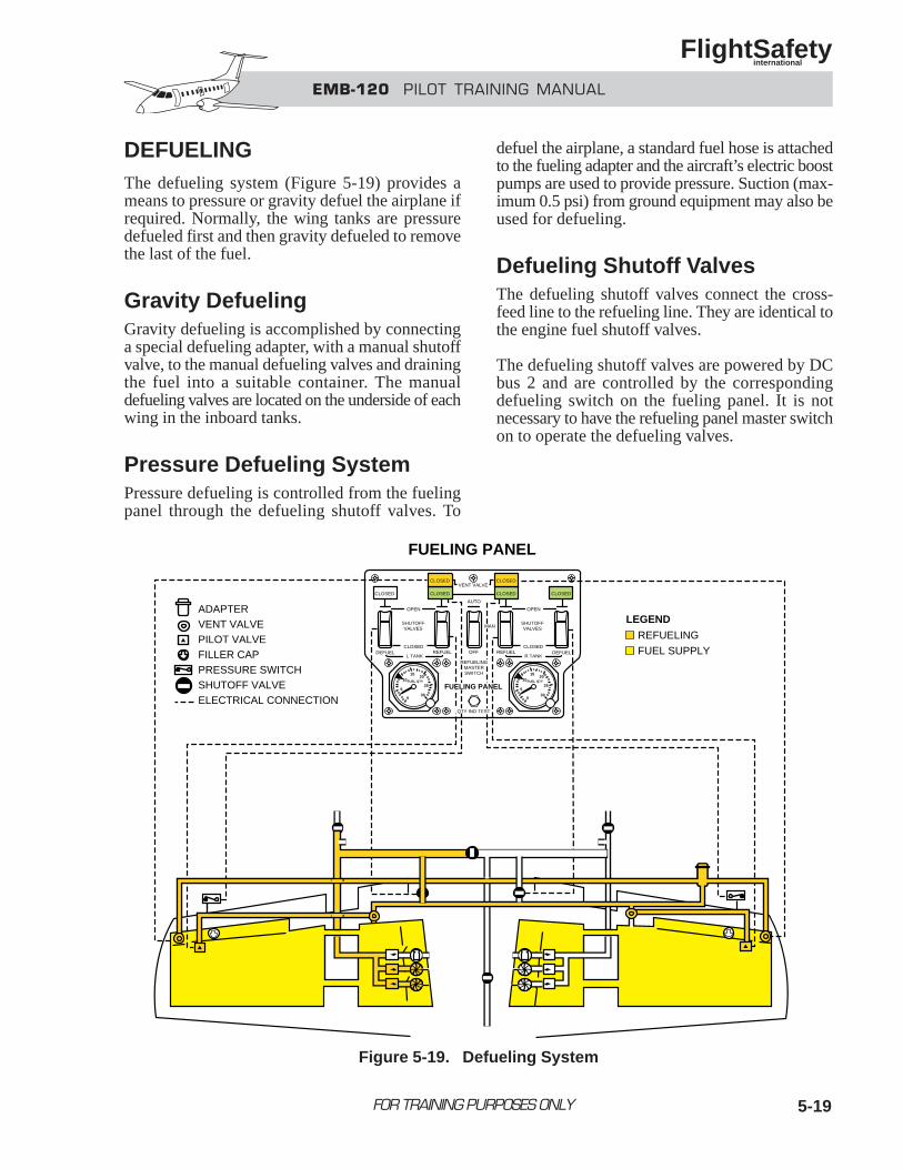
5-19
DEFUELINGThe defueling system (Figure 5-19) provides ameans to pressure or gravity defuel the airplane ifrequired. Normally, the wing tanks are pressuredefueled first and then gravity defueled to removethe last of the fuel.
Gravity DefuelingGravity defueling is accomplished by connectinga special defueling adapter, with a manual shutoffvalve, to the manual defueling valves and drainingthe fuel into a suitable container. The manualdefueling valves are located on the underside of eachwing in the inboard tanks.
Pressure Defueling SystemPressure defueling is controlled from the fuelingpanel through the defueling shutoff valves. To
defuel the airplane, a standard fuel hose is attachedto the fueling adapter and the aircraft’s electric boostpumps are used to provide pressure. Suction (max-imum 0.5 psi) from ground equipment may also beused for defueling.
Defueling Shutoff ValvesThe defueling shutoff valves connect the cross-feed line to the refueling line. They are identical tothe engine fuel shutoff valves.
The defueling shutoff valves are powered by DCbus 2 and are controlled by the correspondingdefueling switch on the fueling panel. It is notnecessary to have the refueling panel master switchon to operate the defueling valves.
FOR TRAINING PURPOSES ONLY
EMB-120 PILOT TRAINING MANUAL
FlightSafety international
REFUELING
FUEL SUPPLY
ADAPTERVENT VALVEPILOT VALVEFILLER CAPPRESSURE SWITCHSHUTOFF VALVEELECTRICAL CONNECTION
FUELING PANEL
LEGEND
VENT VALVECLOSED
CLOSED
CLOSED
CLOSED CLOSEDCLOSED
CLOSED CLOSED
AUTO
OPEN OPEN
SHUTOFFVALVES
SHUTOFFVALVES
DEFUEL REFUEL DEFUELREFUELOFFL TANK R TANK
0
5
1015
20
25
30
FUEL QTY
0
5
1015
20
25
30
FUEL QTY
MAN
FUELING PANEL
REFUELINGMASTERSWITCH
QTY IND TEST
Figure 5-19. Defueling System
5-20 FOR TRAINING PURPOSES ONLY
EMB-120 PILOT TRAINING MANUAL
FlightSafety international
The defueling shutoff valve opens when the respec-tive defueling switch is moved to the OPEN posi-tion. The green CLOSED defueling shutoff valveindicating light remains illuminated until the valvehas reached the fully open position.
Pressure Defueling SystemOperationElectrical power, provided by the airplane electri-cal system or a ground power unit, is required topressure defuel the airplane. A hose with a standardrefueling nozzle is attached to the airplane refuelingadapter.
The defueling shutoff valves are opened by thedefueling switches on the refueling panel while theboost pumps are actuated by their respective switch-es in the cockpit. The fuel flow starts at the collectortank, goes through the selected boost pump, throughthe check valves, into the main fuel lines. From themain fuel lines, the fuel travels through the crossfeed
line to the corresponding defueling shutoff valve.From the shutoff valves, the fuel travels through therefueling shutoff valve line to the refueling adapter.
The master fuel quantity indicators in the cockpitor the repeater fuel quantity indicators at the fuelingpanel can be used to determine the fuel quantity inthe fuel tanks. When the desired fuel quantity isreached, the boost pumps are switched OFF. The defu-el shutoff valves are switched CLOSED and the fuelline is disconnected.
NOTEThe refueling vent valves are not open dur-ing the defueling operation.
In the event of accidental asymmetrical defuelingor refueling, it is possible, on the ground, to trans-fer fuel from one tank into the other tank by defu-eling the high side and refueling the low side. Norefueling hose is required.
The aircraft boost pumps are used to transfer the fuel.
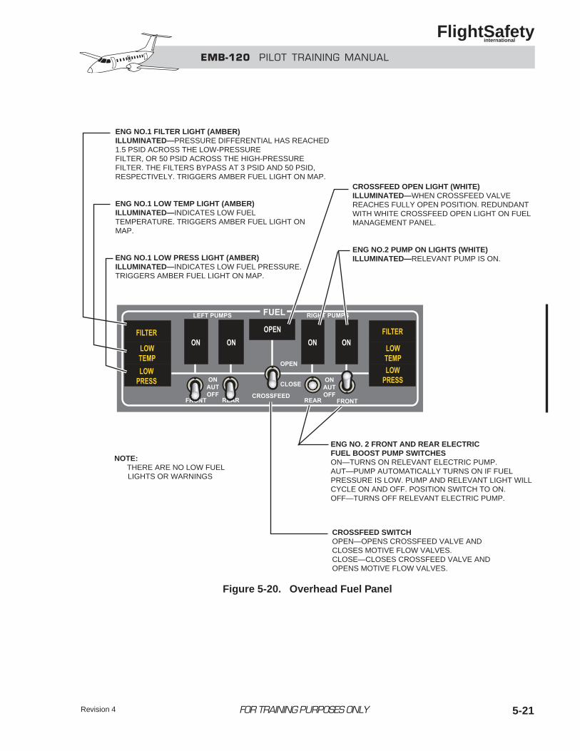
Revision 4 5-21FOR TRAINING PURPOSES ONLY
EMB-120 PILOT TRAINING MANUAL
FlightSafety international
ENG NO.1 FILTER LIGHT (AMBER)ILLUMINATED—PRESSURE DIFFERENTIAL HAS REACHED1.5 PSID ACROSS THE LOW-PRESSUREFILTER, OR 50 PSID ACROSS THE HIGH-PRESSUREFILTER. THE FILTERS BYPASS AT 3 PSID AND 50 PSID,RESPECTIVELY. TRIGGERS AMBER FUEL LIGHT ON MAP.
ENG NO.1 LOW TEMP LIGHT (AMBER)ILLUMINATED—INDICATES LOW FUELTEMPERATURE. TRIGGERS AMBER FUEL LIGHT ONMAP.
ENG NO.1 LOW PRESS LIGHT (AMBER)ILLUMINATED—INDICATES LOW FUEL PRESSURE.TRIGGERS AMBER FUEL LIGHT ON MAP.
CROSSFEED OPEN LIGHT (WHITE)ILLUMINATED—WHEN CROSSFEED VALVEREACHES FULLY OPEN POSITION. REDUNDANT WITH WHITE CROSSFEED OPEN LIGHT ON FUELMANAGEMENT PANEL.
ENG NO.2 PUMP ON LIGHTS (WHITE)ILLUMINATED—RELEVANT PUMP IS ON.
ENG NO. 2 FRONT AND REAR ELECTRICFUEL BOOST PUMP SWITCHESON—TURNS ON RELEVANT ELECTRIC PUMP.AUT—PUMP AUTOMATICALLY TURNS ON IF FUELPRESSURE IS LOW. PUMP AND RELEVANT LIGHT WILLCYCLE ON AND OFF. POSITION SWITCH TO ON.OFF—TURNS OFF RELEVANT ELECTRIC PUMP.
NOTE: THERE ARE NO LOW FUEL LIGHTS OR WARNINGS
CROSSFEED SWITCHOPEN—OPENS CROSSFEED VALVE ANDCLOSES MOTIVE FLOW VALVES.CLOSE—CLOSES CROSSFEED VALVE AND OPENS MOTIVE FLOW VALVES.
Figure 5-20. Overhead Fuel Panel
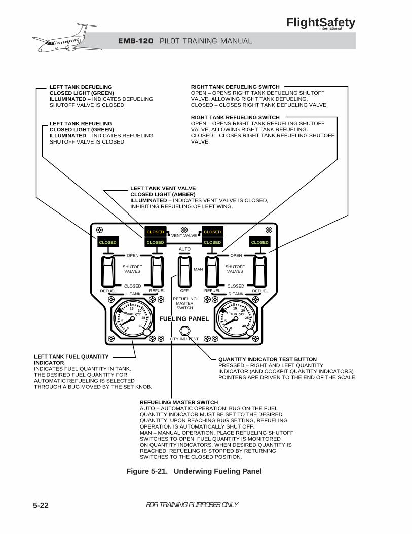
EMB-120 PILOT TRAINING MANUAL
FlightSafety international
FOR TRAINING PURPOSES ONLY5-22
LEFT TANK DEFUELINGCLOSED LIGHT (GREEN)ILLUMINATED – INDICATES DEFUELING SHUTOFF VALVE IS CLOSED.
LEFT TANK REFUELINGCLOSED LIGHT (GREEN)ILLUMINATED – INDICATES REFUELINGSHUTOFF VALVE IS CLOSED.
RIGHT TANK DEFUELING SWITCHOPEN – OPENS RIGHT TANK DEFUELING SHUTOFFVALVE, ALLOWING RIGHT TANK DEFUELING.CLOSED – CLOSES RIGHT TANK DEFUELING VALVE.
RIGHT TANK REFUELING SWITCHOPEN – OPENS RIGHT TANK REFUELING SHUTOFFVALVE, ALLOWING RIGHT TANK REFUELING.CLOSED – CLOSES RIGHT TANK REFUELING SHUTOFFVALVE.
LEFT TANK VENT VALVECLOSED LIGHT (AMBER)ILLUMINATED – INDICATES VENT VALVE IS CLOSED,INHIBITING REFUELING OF LEFT WING.
LEFT TANK FUEL QUANTITYINDICATORINDICATES FUEL QUANTITY IN TANK. THE DESIRED FUEL QUANTITY FOR AUTOMATIC REFUELING IS SELECTEDTHROUGH A BUG MOVED BY THE SET KNOB.
QUANTITY INDICATOR TEST BUTTONPRESSED – RIGHT AND LEFT QUANTITY INDICATOR (AND COCKPIT QUANTITY INDICATORS) POINTERS ARE DRIVEN TO THE END OF THE SCALE.
REFUELING MASTER SWITCHAUTO – AUTOMATIC OPERATION. BUG ON THE FUELQUANTITY INDICATOR MUST BE SET TO THE DESIREDQUANTITY. UPON REACHING BUG SETTING, REFUELINGOPERATION IS AUTOMATICALLY SHUT OFF.MAN – MANUAL OPERATION. PLACE REFUELING SHUTOFFSWITCHES TO OPEN. FUEL QUANTITY IS MONITOREDON QUANTITY INDICATORS. WHEN DESIRED QUANTITY ISREACHED, REFUELING IS STOPPED BY RETURNINGSWITCHES TO THE CLOSED POSITION.
VENT VALVECLOSED
CLOSED
CLOSED
CLOSED CLOSEDCLOSED
CLOSED CLOSED
AUTO
OPEN OPEN
SHUTOFFVALVES
SHUTOFFVALVES
DEFUEL REFUEL DEFUELREFUELOFFL TANK R TANK
0
5
1015
20
25
30
FUEL QTY
0
5
1015
20
25
30
FUEL QTY
MAN
FUELING PANEL
REFUELINGMASTERSWITCH
QTY IND TEST
Figure 5-21. Underwing Fueling Panel
Revision 4 5-23FOR TRAINING PURPOSES ONLY
EMB-120 PILOT TRAINING MANUAL
FlightSafety international
1. The total usable fuel capacity of theEMB-120 is:A. 5,525 poundsB. 5,732 poundsC. 5,777 poundsD. 6,223 pounds
2. The EMB-120 fuel system consists of:A. Four electric boost pumpsB. Four scavenger jet pumpsC. Two main jet pumpsD. All of the above
3. The firewall shutoff valve is operated throughthe:A. Firewall shutoff valve limit switchB. Fuel control unitC. Fire extinguisher T-handleD. Copilot’s fuel monitoring switch
4. Crossfeed operation is indicated by:A. A red lightB. A green lightC. An amber lightD. A white light
5. When pressure refueling, the airplane must beelectrically powered.A. TrueB. False
6. APU fuel used goes through the fueltotalizer.A. TrueB. False
7. In case of a power loss to the fuel flow indicators:A. The digital indication goes blank.B. The digital indication reads LOW.C. The digital indication reads HIGH.D. The digital indication reads OFF.
QUESTIONS
EMB-120 PILOT TRAINING MANUAL
FlightSafety international
FOR TRAINING PURPOSES ONLY 6-i
CHAPTER 6AUXILIARY POWER UNIT
CONTENTS
Page
INTRODUCTION ................................................................................................................... 6-1
GENERAL............................................................................................................................... 6-1
MAJOR SECTIONS................................................................................................................ 6-2
Compressor Section ......................................................................................................... 6-2
Power Section................................................................................................................... 6-3
Accessory Section ............................................................................................................ 6-3
APU SYSTEMS ...................................................................................................................... 6-4
Electrical System.............................................................................................................. 6-4
Fuel System...................................................................................................................... 6-4
Lubrication System .......................................................................................................... 6-5
Pneumatic System ............................................................................................................ 6-5
Automatic Shutdown........................................................................................................ 6-6
APU CONTROL AND MONITORING ................................................................................. 6-6
APU Panel ........................................................................................................................ 6-6
Fuel Totalizer.................................................................................................................... 6-9
OPERATION ........................................................................................................................... 6-9
Operation Notes ............................................................................................................. 6-10
QUESTIONS ......................................................................................................................... 6-12
6-iii
ILLUSTRATIONS
Figure Title Page
6-1 APU Layout ........................................................................................................... 6-2
6-2 Major Sections ....................................................................................................... 6-3
6-3 APU Installation (External) ................................................................................... 6-5
6-4 APU Panel ............................................................................................................. 6-6
6-5 Fuel Totalizer ......................................................................................................... 6-9
6-6 APU Panel ........................................................................................................... 6-11
FOR TRAINING PURPOSES ONLY
EMB-120 PILOT TRAINING MANUAL
FlightSafety international
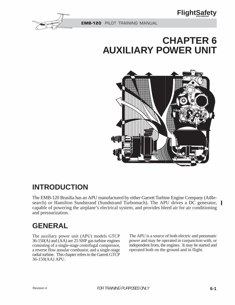
Revision 4 6-1
INTRODUCTIONThe EMB-120 Brasilia has an APU manufactured by either Garrett Turbine Engine Company (AiRe-search) or Hamilton Sundstrand (Sundstrand Turbomach). The APU drives a DC generator,capable of powering the airplane’s electrical system, and provides bleed air for air conditioningand pressurization.
GENERALThe auxiliary power unit (APU) models GTCP36-150(A) and (AA) are 25 SHP gas turbine enginesconsisting of a single-stage centrifugal compressor,a reverse flow annular combustor, and a single-stageradial turbine. This chapter refers to the Garrett GTCP36-150(AA) APU.
The APU is a source of both electric and pneumaticpower and may be operated in conjunction with, orindependent from, the engines. It may be started andoperated both on the ground and in flight.
FOR TRAINING PURPOSES ONLY
EMB-120 PILOT TRAINING MANUAL
FlightSafety international
CHAPTER 6AUXILIARY POWER UNIT
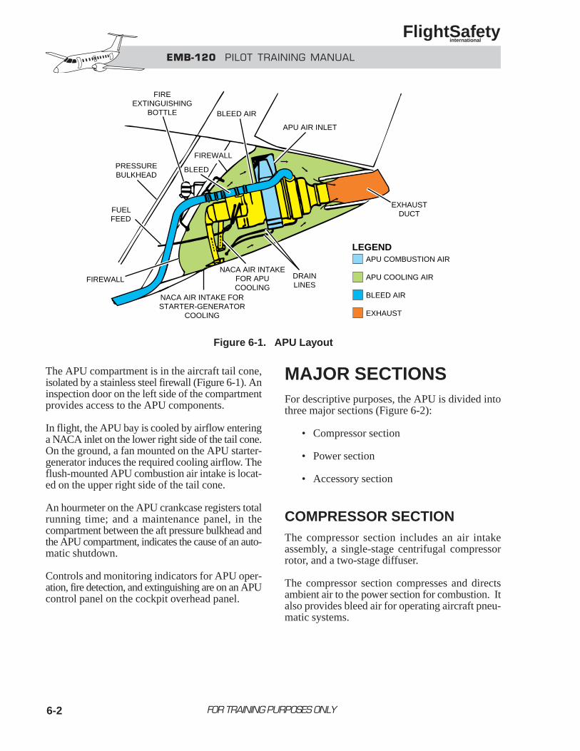
6-2
The APU compartment is in the aircraft tail cone,isolated by a stainless steel firewall (Figure 6-1). Aninspection door on the left side of the compartmentprovides access to the APU components.
In flight, the APU bay is cooled by airflow enteringa NACA inlet on the lower right side of the tail cone.On the ground, a fan mounted on the APU starter-generator induces the required cooling airflow. Theflush-mounted APU combustion air intake is locat-ed on the upper right side of the tail cone.
An hourmeter on the APU crankcase registers totalrunning time; and a maintenance panel, in thecompartment between the aft pressure bulkhead andthe APU compartment, indicates the cause of an auto-matic shutdown.
Controls and monitoring indicators for APU oper-ation, fire detection, and extinguishing are on an APUcontrol panel on the cockpit overhead panel.
MAJOR SECTIONSFor descriptive purposes, the APU is divided intothree major sections (Figure 6-2):
• Compressor section
• Power section
• Accessory section
COMPRESSOR SECTIONThe compressor section includes an air intakeassembly, a single-stage centrifugal compressorrotor, and a two-stage diffuser.
The compressor section compresses and directsambient air to the power section for combustion. Italso provides bleed air for operating aircraft pneu-matic systems.
FOR TRAINING PURPOSES ONLY
EMB-120 PILOT TRAINING MANUAL
FlightSafety international
FIREEXTINGUISHING
BOTTLE BLEED AIR
APU AIR INLET
EXHAUSTDUCT
DRAINLINES
NACA AIR INTAKEFOR APUCOOLING
NACA AIR INTAKE FORSTARTER-GENERATOR
COOLING
FUELFEED
FIREWALL
PRESSUREBULKHEAD
FIREWALL
BLEED
APU COMBUSTION AIR
APU COOLING AIR
BLEED AIR
EXHAUST
LEGEND
Figure 6-1. APU Layout
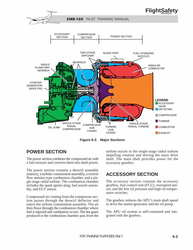
6-3
POWER SECTIONThe power section combines the compressed air witha fuel mixture and converts them into shaft power.
The power section contains a deswirl assembly(stators), a turbine containment assembly, a reverseflow annular-type combustion chamber, and a sin-gle-stage radial turbine. The combustion chamberincludes the spark igniter plug, fuel nozzle assem-bly, and EGT sensor.
Compressed air coming from the compressor sec-tion passes through the deswirl deflector andenters the turbine containment assembly. The airthen flows through the combustion chamber wherefuel is injected and combustion occurs. The hot gasesproduced in the combustion chamber pass from the
turbine nozzle to the single-stage radial turbineimpelling rotation and driving the main driveshaft. The main shaft provides power for theaccessory gearbox.
ACCESSORY SECTIONThe accessory section contains the accessorygearbox, fuel control unit (FCU), overspeed sen-sor, and the low oil pressure and high oil temper-ature switches.
The gearbox reduces the APU’s main shaft speedto drive the starter-generator and the oil pump.
The APU oil system is self-contained and inte-grated with the gearbox.
FOR TRAINING PURPOSES ONLY
EMB-120 PILOT TRAINING MANUAL
FlightSafety international
ACCESSORYSECTION
COMPRESSORSECTION POWER SECTION
SINGLEPLANETARY
GEARBOX
BLEED PORT FUEL ATOMIZINGNOZZLES
ANNULARCOMBUSTOR
SINGLE-STAGERADIAL TURBINETURBINE
HUBCASING
COMPRESSORHUB
CASING
SINGLE-STAGERADIAL
COMPRESSOROIL SUMP
STARTER-GENERATOR
DRIVE PAD
TWO-STAGEDIFFUSER
ACCESSORYGEARAIR INTAKE
COMPRESSOR
TURBINE
COMBUSTOR
EXHAUST
LEGEND
BEARINGS
Figure 6-2. Major Sections
6-4
APU SYSTEMSThe APU systems consist of the following:
• Electrical
• Fuel
• Lubrication
• Pneumatic
• Automatic shutdown
ELECTRICAL SYSTEMThe APU’s electrical system includes the follow-ing subassemblies:
• Electronic control unit (ECU)
• Starter-generator
• Ignition unit
Electronic Control Unit (ECU)The ECU governs the APU. It controls the startingsequence, acceleration, governed speed operation,temperature limits and shutdown. It incorporatesthe fuel management control logic and the load con-trol valve logic.
The ECU receives input signals from:
• High oil pressure switch
• High oil temperature switch
• Starter-generator
• Master control switch
• Auxiliary shutdown switch
• Overspeed sensor
• Exhaust gas temperature (EGT) sensor
• Load control valve actuating switch
The ECU provides output signals to:
• Fuel control unit (FCU)
• Fuel solenoid valve
• Ignition unit
• Starting relay
• Hourmeter
• Maintenance panel
Starter-GeneratorThe APU starter-generator is physically and func-tionally identical to the engine starter-generator.
During the APU start sequence, the starter-gener-ator functions as a starter and drives the compres-sor/turbine. When the starting cycle is over, thestarter-generator operates as an APU-driven generator.
The APU starter-generator is attached to the acces-sory gearbox on the forward section of the APU.
Ignition UnitThe ignition unit is used to develop the output volt-age to energize the igniter plug. The unit is a capac-itive discharge, energy storage system. It is poweredby 28 VDC from the airplane’s electrical systemand emits pulsing high voltage (18 to 24 KV) tothe igniter.
FUEL SYSTEMThe APU fuel system provides pressurized, meteredfuel to the combustion chamber. The system includesa fuel control unit (FCU), fuel flow dividers, and fuelnozzles. It provides fuel in accordance with the pre-programmed schedule in the FCU.
The FCU pressurizes and meters fuel going to thefuel flow dividers. The fuel flow dividers distributethe fuel from the FCU to six fuel nozzles; the noz-zles atomize and inject the fuel into the combustionchamber in a swirl pattern.
FOR TRAINING PURPOSES ONLY
EMB-120 PILOT TRAINING MANUAL
FlightSafety international
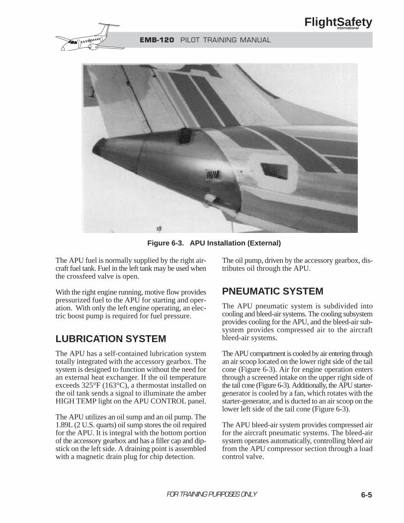
EMB-120 PILOT TRAINING MANUAL
FlightSafety international
FOR TRAINING PURPOSES ONLY 6-5
The APU fuel is normally supplied by the right air-craft fuel tank. Fuel in the left tank may be used whenthe crossfeed valve is open.
With the right engine running, motive flow providespressurized fuel to the APU for starting and oper-ation. With only the left engine operating, an elec-tric boost pump is required for fuel pressure.
LUBRICATION SYSTEMThe APU has a self-contained lubrication systemtotally integrated with the accessory gearbox. Thesystem is designed to function without the need foran external heat exchanger. If the oil temperatureexceeds 325°F (163°C), a thermostat installed onthe oil tank sends a signal to illuminate the amberHIGH TEMP light on the APU CONTROL panel.
The APU utilizes an oil sump and an oil pump. The1.89L (2 U.S. quarts) oil sump stores the oil requiredfor the APU. It is integral with the bottom portionof the accessory gearbox and has a filler cap and dip-stick on the left side. A draining point is assembledwith a magnetic drain plug for chip detection.
The oil pump, driven by the accessory gearbox, dis-tributes oil through the APU.
PNEUMATIC SYSTEMThe APU pneumatic system is subdivided intocooling and bleed-air systems. The cooling subsystemprovides cooling for the APU, and the bleed-air sub-system provides compressed air to the aircraftbleed-air systems.
The APU compartment is cooled by air entering throughan air scoop located on the lower right side of the tailcone (Figure 6-3). Air for engine operation entersthrough a screened intake on the upper right side ofthe tail cone (Figure 6-3). Additionally, the APU starter-generator is cooled by a fan, which rotates with thestarter-generator, and is ducted to an air scoop on thelower left side of the tail cone (Figure 6-3).
The APU bleed-air system provides compressed airfor the aircraft pneumatic systems. The bleed-airsystem operates automatically, controlling bleed airfrom the APU compressor section through a loadcontrol valve.
Figure 6-3. APU Installation (External)
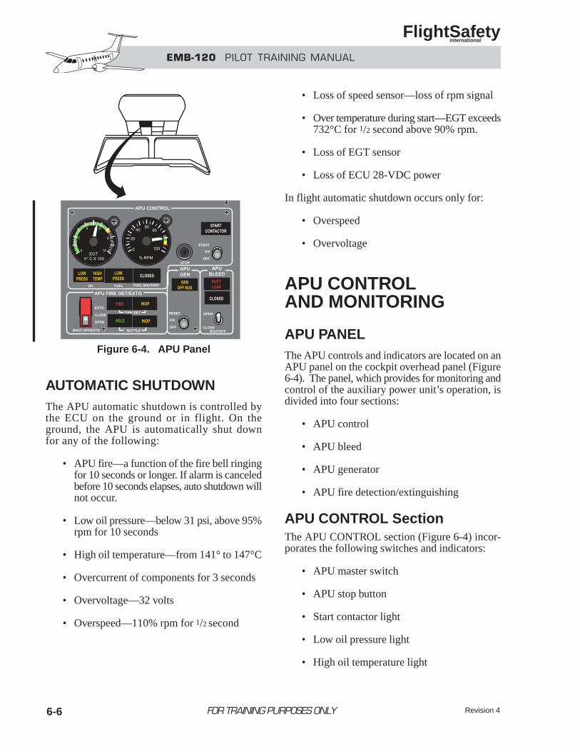
Revision 46-6
AUTOMATIC SHUTDOWNThe APU automatic shutdown is controlled bythe ECU on the ground or in flight. On theground, the APU is automatically shut downfor any of the following:
• APU fire—a function of the fire bell ringingfor 10 seconds or longer. If alarm is canceledbefore 10 seconds elapses, auto shutdown willnot occur.
• Low oil pressure—below 31 psi, above 95%rpm for 10 seconds
• High oil temperature—from 141° to 147°C
• Overcurrent of components for 3 seconds
• Overvoltage—32 volts
• Overspeed—110% rpm for 1/2 second
• Loss of speed sensor—loss of rpm signal
• Over temperature during start—EGT exceeds732°C for 1/2 second above 90% rpm.
• Loss of EGT sensor
• Loss of ECU 28-VDC power
In flight automatic shutdown occurs only for:
• Overspeed
• Overvoltage
APU CONTROLAND MONITORING
APU PANELThe APU controls and indicators are located on anAPU panel on the cockpit overhead panel (Figure6-4). The panel, which provides for monitoring andcontrol of the auxiliary power unit’s operation, isdivided into four sections:
• APU control
• APU bleed
• APU generator
• APU fire detection/extinguishing
APU CONTROL SectionThe APU CONTROL section (Figure 6-4) incor-porates the following switches and indicators:
• APU master switch
• APU stop button
• Start contactor light
• Low oil pressure light
• High oil temperature light
FOR TRAINING PURPOSES ONLY
EMB-120 PILOT TRAINING MANUAL
FlightSafety international
Figure 6-4. APU Panel
6-7
• Low fuel pressure light
• APU fuel closed shutoff valve lithe
• APU rpm indicator
• Exhaust gas temperature (EGT) indicator
Master Switch—The APU master switch is athree-position (START/ON/OFF) switch. Switch posi-tion functions are as follows:
• START— Initiates start cycle, (momentaryposition).
• ON—Applies power to the ECU, opens thefuel shutoff valve, and keeps the APU run-ning during normal operation.
• OFF—Commands the APU shutdown. Deen-ergizes the ECU, closes the fuel shutoffvalve, and deenergizes rpm and EGT indicatorsand indication lights.
The white bleed-air and fuel shutoff CLOSEDlights remain illuminated on the APU con-trol panel for ten seconds after the APUmaster switch is selected to off.
STOP Button—The APU stop button shuts downthe APU by sending an electronic 110% rpm over-speed signal which simultaneously checks the ECUfault protection circuit. It is normally used to shutdown the APU so that rpm and EGT indications maybe monitored during spool down.
START CONTACTOR Light—When the startingcycle is initiated, the white START CONTACTORlight illuminates indicating the start relay is ener-gized. At 50% rpm, the ECU disengages the starterand extinguishes the light.
Oil LOW PRESS Light—If oil pressure drops below31 psi for over 10 seconds with the APU operatingabove 95% rpm, the amber LOW PRESS lightilluminates. Also, the amber APU light on theMAP illuminates, triggering a single chime aural alert,and the master CAUTION lights flash.
Fuel LOW PRESS Light—When the fuel pres-sure in the APU falls below 9 psi, a pressure
switch installed in the fuel supply line illuminatesthe amber fuel LOW PRESS light. Also, the amberAPU light on the MAP illuminates, triggering a sin-gle chime aural alert, and the master CAUTION lightsflash.
The APU will not start with the APU fuel LOWPRESS light illuminated.
Fuel Shutoff CLOSED Light—The white fuel shut-off CLOSED light illuminates when the APU fuelshutoff valve, located in the right wing root area, isfully closed.
rpm Indicator—The APU utilizes a magneticsensor in the reduction gearbox to sense APU rpm.The sensor provides a signal to the ECU where itis processed and sent to the rpm indicator.
The indicator is powered by DC bus 2. When a poweror signal loss occurs, the pointer indicates below zeroon the scale.
The rpm indicator is marked as follows:
• GREEN arc, from 96 to 104% rpm, indicatesthe normal operating range.
• YELLOW arc, from 104 to 110% rpm, indi-cates the caution range of operation.
• RED radial, at 110% rpm, indicates themaximum permitted rpm.
Exhaust Gas Temperature (EGT) Indicator—TheAPU utilizes a thermocouple in the exhaust duct tosense the exhaust temperature. The thermocouplesends a signal to the ECU where it is processed andsent to the EGT indicator.
The indicator is powered by DC bus 2. When a poweror signal loss occurs, the pointer indicates below zeroon the scale.
The EGT indicator is marked as follows:
• GREEN arc, from 0 to 680°C, indicates thenormal operating range.
• YELLOW arc, from 680 to 732°C, indi-cates caution range of operation.
FOR TRAINING PURPOSES ONLY
EMB-120 PILOT TRAINING MANUAL
FlightSafety international
6-8
• RED radial, at 732° C, indicates the maximumpermitted EGT .
APU BLEED SectionThe APU BLEED section (Figure 6-4) has the fol-lowing control switch and indicators:
• APU bleed shutoff switch
• APU duct leak light
• APU bleed closed light
SHUTOFF Switch—The APU bleed SHUTOFFswitch, through a torque motor and the ECU, con-trols the bleed shutoff valve. Switch position func-tions are as follows:
• OPEN—Four seconds after the APU reaches95% rpm, the bleed valve opens allowingbleed air to enter the aircraft pneumatic system.
• CLOSE—The bleed shutoff valve closes and the white APU bleed CLOSED light illuminates.
The bleed shutoff valve also closes if the APUrpm drops below 95% for an EGT overtem-perature, or when the APU is supplying thesame pack as an engine.
Bleed CLOSED Light—The white APU bleedCLOSED light illuminates when the APU bleed shut-off valve is closed.
DUCT LEAK Light—When a bleed-air leakoccurs and the temperature exceeds 71°C (160°F),temperature sensors located along the lines send asignal illuminating the red DUCT LEAK light.Also, the red DUCT LEAK light on the MAPflashes, the master WARNING lights flash, and avoice message “DUCT LEAK” is heard.
APU GEN SectionThe APU is equipped with a starter-generator identi-cal to the one used for the engines. Generator opera-tion is covered in Chapter 2, Electrical Power Systems.
The APU GEN section (Figure 6-4) consists of thefollowing:
• APU generator switch
• GEN OFF BUS light.
Generator Switch—The APU generator switch isa three-position switch with the following functions:
• RESET—Electrically resets the generator,(momentarily position).
• ON—Connects the APU generator to thecentral DC bus.
• OFF—Disconnects the APU generator fromthe central DC bus.
GEN OFF BUS Light—The amber GEN OFFBUS light illuminates when the APU generator isdisconnected from the central DC bus.
APU FIRE DET/EXTG SectionThe APU FIRE DET/EXTG section (Figure 6-4) con-tains the following switches and indicators:
• APU shutoff/extinguishing switch
• APU fire warning light
• APU fire detector inoperative light
• APU fire extinguishing bottle integrity light
• APU fire extinguishing bottle pressure con-dition light
SHUTOFF/EXTG Switch—The SHUTOFF/EXTGswitch is a guarded, three-position switch, withthe following positions:
• EXTNG—Discharges the fire extinguish-ing agent into the APU compartment.
• CLOSE—Closes the APU fuel shutoff andAPU bleed valves, disconnects the APU
FOR TRAINING PURPOSES ONLY
EMB-120 PILOT TRAINING MANUAL
FlightSafety international
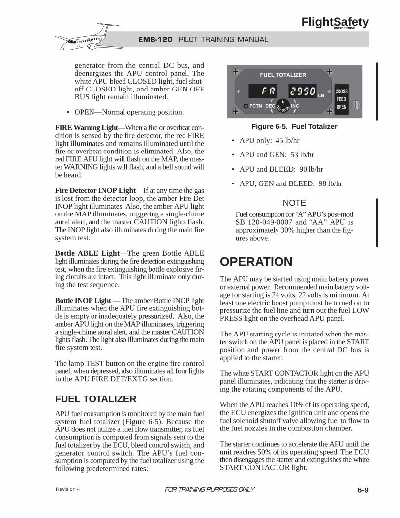
Revision 4 6-9
generator from the central DC bus, anddeenergizes the APU control panel. Thewhite APU bleed CLOSED light, fuel shut-off CLOSED light, and amber GEN OFFBUS light remain illuminated.
• OPEN—Normal operating position.
FIRE Warning Light—When a fire or overheat con-dition is sensed by the fire detector, the red FIRElight illuminates and remains illuminated until thefire or overheat condition is eliminated. Also, thered FIRE APU light will flash on the MAP, the mas-ter WARNING lights will flash, and a bell sound willbe heard.
Fire Detector INOP Light—If at any time the gasis lost from the detector loop, the amber Fire DetINOP light illuminates. Also, the amber APU lighton the MAP illuminates, triggering a single-chimeaural alert, and the master CAUTION lights flash.The INOP light also illuminates during the main firesystem test.
Bottle ABLE Light—The green Bottle ABLElight illuminates during the fire detection extinguishingtest, when the fire extinguishing bottle explosive fir-ing circuits are intact. This light illuminate only dur-ing the test sequence.
Bottle INOP Light — The amber Bottle INOP lightilluminates when the APU fire extinguishing bot-tle is empty or inadequately pressurized. Also, theamber APU light on the MAP illuminates, triggeringa single-chime aural alert, and the master CAUTIONlights flash. The light also illuminates during the mainfire system test.
The lamp TEST button on the engine fire controlpanel, when depressed, also illuminates all four lightsin the APU FIRE DET/EXTG section.
FUEL TOTALIZERAPU fuel consumption is monitored by the main fuelsystem fuel totalizer (Figure 6-5). Because theAPU does not utilize a fuel flow transmitter, its fuelconsumption is computed from signals sent to thefuel totalizer by the ECU, bleed control switch, andgenerator control switch. The APU’s fuel con-sumption is computed by the fuel totalizer using thefollowing predetermined rates:
• APU only: 45 lb/hr
• APU and GEN: 53 lb/hr
• APU and BLEED: 90 lb/hr
• APU, GEN and BLEED: 98 lb/hr
NOTEFuel consumption for “A” APU’s post-modSB 120-049-0007 and “AA” APU isapproximately 30% higher than the fig-ures above.
OPERATIONThe APU may be started using main battery poweror external power. Recommended main battery volt-age for starting is 24 volts, 22 volts is minimum. Atleast one electric boost pump must be turned on topressurize the fuel line and turn out the fuel LOWPRESS light on the overhead APU panel.
The APU starting cycle is initiated when the mas-ter switch on the APU panel is placed in the STARTposition and power from the central DC bus isapplied to the starter.
The white START CONTACTOR light on the APUpanel illuminates, indicating that the starter is driv-ing the rotating components of the APU.
When the APU reaches 10% of its operating speed,the ECU energizes the ignition unit and opens thefuel solenoid shutoff valve allowing fuel to flow tothe fuel nozzles in the combustion chamber.
The starter continues to accelerate the APU until theunit reaches 50% of its operating speed. The ECUthen disengages the starter and extinguishes the whiteSTART CONTACTOR light.
FOR TRAINING PURPOSES ONLY
EMB-120 PILOT TRAINING MANUAL
FlightSafety international
Figure 6-5. Fuel Totalizer
Revision 46-10
The APU continues to accelerate until it reaches 95%rpm where the ignition circuit is deenergized. Afterthe ignition circuit deenergizes, the ECU permits shaftpower extraction through the starter-generator in thegenerator mode and, after 4 seconds, pneumatic powerextraction through the load control valve.
Once the APU is started, the electrical power to keepit running is supplied by the APU generator regard-less of the position of the electrical panel PWRSELECT switch or the APU generator switch.
The APU may be started on the ground or in flight.In flight, it may be started at altitudes up to 20,000feet and at airspeeds between 135 to 240 KIAS.
Refer to the Aircraft Flight Manual limitationssection for specific limitations.
OPERATION NOTES• During the engine/APU fire detection/extin-
guishing test, if the TEST button is heldmore than 10 seconds without canceling thefire bell, the APU will automatically shut down.
• Due to its intake location on the upper rightside of the tail cone, the APU has a tenden-cy to ingest right engine exhaust fumes,especially with the propeller feathered.Therefore, after right engine start, recommendusing engine bleed instead of APU bleed.
• The APU bleed logic is set up so that the APUcannot supply bleed air to the same air con-ditioning pack that is being supplied by enginebleed. In this case, priority is given to the engineand the APU bleed closes automatically.
• Do not spray water, cleaning, or deicing flu-ids into the tail cone APU maintenance doorlocated on the upper right tail cone forward ofthe APU firewall. These fluids may penetratethe APU ECU and cause the APU to overspeed.
• Once the APU has been shut down and theAPU master switch has been turned off, donot turn the switch back on for at least oneminute. If the APU has not spooled down com-pletely and the master switch is turned on, thefuel may be turned on again with a resultingstack fire.
• APU bleed may be utilized to supply airconditioning and pressurization during take-off to reduce engine temperatures and toincrease aircraft performance.
• To prevent electrical transients from affect-ing sensitive electronic equipment, placethe backup battery switch in the ARM posi-tion prior to APU start.
FOR TRAINING PURPOSES ONLY
EMB-120 PILOT TRAINING MANUAL
FlightSafety international
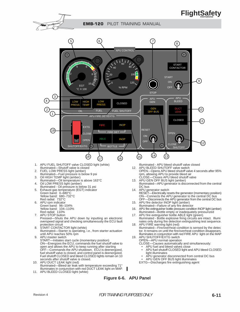
Revision 4 6-11
1. APU FUEL SHUTOFF valve CLOSED light (white)Illuminated—Shutoff valve is closed
2. FUEL LOW PRESS light (amber)Illuminated—Fuel pressure is below 9 psi
3. Oil HIGH TEMP light (amber)Illuminated—Oil temperature is above 163°C
4. Oil LOW PRESS light (amber)Illuminated - Oil pressure is below 31 psi
5. Exhaust gas temperature (EGT) indicatorGreen band: 0–680°CYellow band: 680–732°CRed radial: 732°C
6. APU rpm indicatorGreen band: 96–104%Yellow band: 104–110%Red radial: 110%
7. APU STOP buttonPressed—Shuts the APU down by inputting an electronicoverspeed signal and checking simultaneously the ECU faultprotection circuit
8. START CONTACTOR light (white)Illuminated—Starter is operating, i.e., from starter actuationuntil APU reaches 50% rpm
9. APU master switchSTART—Initiates start cycle (momentary position)ON—Energizes the ECU, commands the fuel shutoff valve toopen and allows the APU to keep running after startingOFF—Commands the APU shutdown. ECU is deenergized,fuel shutoff valve is closed, and control panel is deenergized.Fuel shutoff CLOSED and bleed CLOSED lights remain on 10seconds after shutoff valve is closed.
10. APU DUCT LEAK light (red)Illuminated—Bleed-air leak with temperature exceeding 71°Illuminates in conjunction with red DUCT LEAK light on MAP.
11. APU BLEED CLOSED light (white)
Illuminated - APU bleed shutoff valve closed12. APU BLEED SHUTOFF valve switch
OPEN—Opens APU bleed shutoff valve 4 seconds after 95%rpm, allowing APU to provide bleed airCLOSE—Closes APU bleed shutoff valve
13. APU GEN OFF BUS light (amber)Illuminated—APU generator is disconnected from the centralDC bus
14. APU generator switchRESET—Electrically resets the generator (momentary position)ON—Connects the APU generator to the central DC busOFF—Disconnects the APU generator from the central DC bus
15. APU fire detector INOP light (amber)Illuminated—Failure of any fire detector
16. APU fire extinguisher bottle pressure condition INOP light (amber)Illuminated—Bottle empty or inadequately pressurized
17. APU fire extinguisher bottle ABLE light (green)Illuminated - Bottle explosive firing circuits are intact. Illuminates only during fire detection extinguishing test sequence.
18. APU FIRE warning light (red)Illuminated—Fire/overheat condition is sensed by the detector. It remains on until the fire/overheat condition disappears.Illuminates in conjunction with red FIRE APU light on the MAP
19. APU SHUTOFF/EXTG switchOPEN—APU normal operationCLOSE—Causes automatically and simultaneously:
• APU fuel and bleed valves close• APU fuel shutoff CLOSED light and APU bleed CLOSED
light illuminates• APU generator disconnected from central DC bus• APU GEN OFF BUS light illuminates
EXTG—Discharges fire extinguishing agent
FOR TRAINING PURPOSES ONLY
EMB-120 PILOT TRAINING MANUAL
FlightSafety international
APU CONTROL
STARTCONTACTOR
START
ON
OFF
STOP
DUCTLEAK
CLOSED
GENOFF BUS
RESET
ON
OFF
OPEN
CLOSESHUTOFF
APUGEN
APUBLEEDLOW
PRESSHIGHTEMP
LOWPRESS CLOSED
OIL FUEL FUEL SHUTOFF
FIRE DET
BOTTLE
APU FIRE DET/EXTG
EXTG
CLOSE
OPEN
SHUTOFF/EXTG
0
2
4 6
8
10
% RPM
0
20
40
6080
100
120
5 6 78
43
19
21
9
10
11
12
131415161718
EGT°C X 100
FIRE
ABLE
INOP
INOP
Figure 6-6. APU Panel
6-12
1. The APU provides a source of:A. Pneumatic powerB. Electrical powerC. Fuel flow pressureD. Both A and B
2. The APU can receive fuel from the left fuel tank:A. TrueB. False
3. The APU will automatically shutdown ifrotating parts exceed:A. 102%B. 105%C. 110%D. 115%
4. During the APU start cycle, the:A. GCU commands starter disengagementB. FCU commands starter disengagementC. ECU commands starter disengagementD. EEC commands starter disengagement
5. The APU can be operated in flight:A. TrueB. False
FOR TRAINING PURPOSES ONLY
EMB-120 PILOT TRAINING MANUAL
FlightSafety international
QUESTIONS
Revision 4 7-iFOR TRAINING PURPOSES ONLY
EMB-120 PILOT TRAINING MANUAL
FlightSafety international
CHAPTER 7POWERPLANT
CONTENTS
Page
INTRODUCTION ................................................................................................................... 7-1
GENERAL............................................................................................................................... 7-1
ENGINE................................................................................................................................... 7-2
General ............................................................................................................................. 7-2
Major Sections ................................................................................................................. 7-4
Engine Systems ................................................................................................................ 7-7
Engine Control ............................................................................................................... 7-16
Engine Monitoring ......................................................................................................... 7-24
PROPELLER......................................................................................................................... 7-29
General ........................................................................................................................... 7-29
Propeller Assembly........................................................................................................ 7-29
Propeller Control Components....................................................................................... 7-31
Propeller Safety Features .............................................................................................. 7-38
Propeller Operation........................................................................................................ 7-43
Propeller Synchronization System................................................................................. 7-44
QUESTIONS.......................................................................................................................... 7-47
Revision 4 7-iii
ILLUSTRATIONS
Figure Title Page
7-1 Engine Installation.................................................................................................... 7-2
7-2 Engine Layout .......................................................................................................... 7-3
7-3 Engine Cross Section (Typical) ................................................................................ 7-4
7-4 Stations ..................................................................................................................... 7-6
7-5 Engine Cowlings....................................................................................................... 7-7
7-6 Engine Oil Tank/Sight Glass .................................................................................... 7-8
7-7 Engine Oil System.................................................................................................... 7-9
7-8 Hydromechanical Metering Unit (HMU)............................................................... 7-12
7-9 Fuel Flow Indicators............................................................................................... 7-13
7-10 Start/Ignition Panel................................................................................................. 7-14
7-11 EEC Input/Output Schematic ................................................................................. 7-16
7-12 EEC Controls and Indicators .................................................................................. 7-17
7-13 Center Pedestal Console......................................................................................... 7-20
7-14 Engine Control System Schematic ......................................................................... 7-21
7-15 IDLE 1 (2) UNLK Light ........................................................................................ 7-22
7-16 Engine Instrument Location ................................................................................... 7-24
7-17 Torque Indicating System....................................................................................... 7-25
7-18 Engine Instruments................................................................................................. 7-27
7-19 Powerplant Control Panels .................................................................................... 7-28
7-20 Hamilton Sundstrand 14RF-9 “Commuter” Propeller ........................................... 7-29
7-21 Blade Construction................................................................................................. 7-30
7-22 Propeller Control Components............................................................................... 7-31
7-23 Propeller Oil Supply............................................................................................... 7-32
FOR TRAINING PURPOSES ONLY
EMB-120 PILOT TRAINING MANUAL
FlightSafety international
Revision 47-iv
7-24 Propeller Control System ....................................................................................... 7-34
7-25 Propeller Servomechanism during Pitch Change Operations ................................ 7-37
7-26 Powerplant Control Panel ...................................................................................... 7-39
7-27 AUTO FEATHER Control Panel ........................................................................... 7-42
7-28 Synchronization Control Panel............................................................................... 7-44
7-29 Propeller System Controls and Indicators .............................................................. 7-46
FOR TRAINING PURPOSES ONLY
EMB-120 PILOT TRAINING MANUAL
FlightSafety international
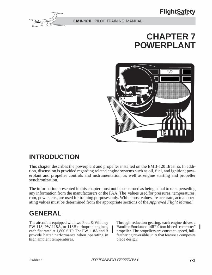
Revision 4 7-1
INTRODUCTIONThis chapter describes the powerplant and propeller installed on the EMB-120 Brasilia. In addi-tion, discussion is provided regarding related engine systems such as oil, fuel, and ignition; pow-erplant and propeller controls and instrumentation; as well as engine starting and propellersynchronization.
The information presented in this chapter must not be construed as being equal to or supersedingany information from the manufacturers or the FAA. The values used for pressures, temperatures,rpm, power, etc., are used for training purposes only. While most values are accurate, actual oper-ating values must be determined from the appropriate sections of the Approved Flight Manual.
GENERALThe aircraft is equipped with two Pratt & WhitneyPW 118, PW 118A, or 118B turboprop engines,each flat rated at 1,800 SHP. The PW 118A and Bprovide better performance when operating inhigh ambient temperatures.
Through reduction gearing, each engine drives aHamilton Sundstrand 14RF-9 four-bladed “commuter”propeller. The propellers are constant- speed, full-feathering reversible units that feature a compositeblade design.
#1 DCGEN
FOR TRAINING PURPOSES ONLY
EMB-120 PILOT TRAINING MANUAL
FlightSafety international
CHAPTER 7POWERPLANT
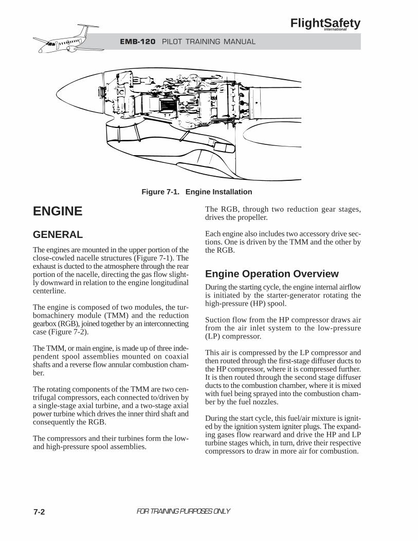
EMB-120 PILOT TRAINING MANUAL
FlightSafety international
7-2
ENGINE
GENERALThe engines are mounted in the upper portion of theclose-cowled nacelle structures (Figure 7-1). Theexhaust is ducted to the atmosphere through the rearportion of the nacelle, directing the gas flow slight-ly downward in relation to the engine longitudinalcenterline.
The engine is composed of two modules, the tur-bomachinery module (TMM) and the reductiongearbox (RGB), joined together by an interconnectingcase (Figure 7-2).
The TMM, or main engine, is made up of three inde-pendent spool assemblies mounted on coaxialshafts and a reverse flow annular combustion cham-ber.
The rotating components of the TMM are two cen-trifugal compressors, each connected to/driven bya single-stage axial turbine, and a two-stage axialpower turbine which drives the inner third shaft andconsequently the RGB.
The compressors and their turbines form the low-and high-pressure spool assemblies.
The RGB, through two reduction gear stages,drives the propeller.
Each engine also includes two accessory drive sec-tions. One is driven by the TMM and the other bythe RGB.
Engine Operation OverviewDuring the starting cycle, the engine internal airflowis initiated by the starter-generator rotating thehigh-pressure (HP) spool.
Suction flow from the HP compressor draws airfrom the air inlet system to the low-pressure(LP) compressor.
This air is compressed by the LP compressor andthen routed through the first-stage diffuser ducts tothe HP compressor, where it is compressed further.It is then routed through the second stage diffuserducts to the combustion chamber, where it is mixedwith fuel being sprayed into the combustion cham-ber by the fuel nozzles.
During the start cycle, this fuel/air mixture is ignit-ed by the ignition system igniter plugs. The expand-ing gases flow rearward and drive the HP and LPturbine stages which, in turn, drive their respectivecompressors to draw in more air for combustion.
FOR TRAINING PURPOSES ONLY
Figure 7-1. Engine Installation
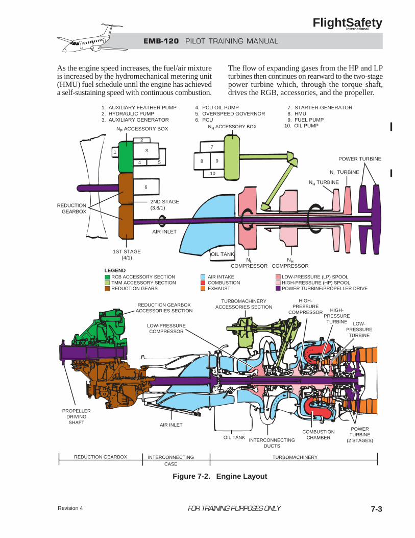
EMB-120 PILOT TRAINING MANUAL
FlightSafety international
Revision 4 7-3
As the engine speed increases, the fuel/air mixtureis increased by the hydromechanical metering unit(HMU) fuel schedule until the engine has achieveda self-sustaining speed with continuous combustion.
The flow of expanding gases from the HP and LPturbines then continues on rearward to the two-stagepower turbine which, through the torque shaft,drives the RGB, accessories, and the propeller.
FOR TRAINING PURPOSES ONLY
REDUCTION GEARBOXACCESSORIES SECTION
TURBOMACHINERYACCESSORIES SECTION
HIGH-PRESSURE
COMPRESSOR HIGH-PRESSURETURBINE LOW-
PRESSURETURBINE
POWERTURBINE
(2 STAGES)
COMBUSTIONCHAMBERINTERCONNECTING
DUCTS
OIL TANK
AIR INLET
PROPELLERDRIVINGSHAFT
REDUCTION GEARBOX INTERCONNECTINGCASE
TURBOMACHINERY
LOW-PRESSURECOMPRESSOR
OIL TANK
AIR INLET
1ST STAGE(4/1)
2ND STAGE(3.8/1)REDUCTION
GEARBOX
NP ACCESSORY BOX
2
3
4 5
1
6
7
8 9
NH ACCESSORY BOX
NLCOMPRESSOR
NHCOMPRESSOR
NH TURBINE
NL TURBINE
POWER TURBINE
1. AUXILIARY FEATHER PUMP2. HYDRAULIC PUMP3. AUXILIARY GENERATOR
4. PCU OIL PUMP5. OVERSPEED GOVERNOR6. PCU
7. STARTER-GENERATOR8. HMU9. FUEL PUMP
RCB ACCESSORY SECTIONTMM ACCESSORY SECTIONREDUCTION GEARS
AIR INTAKECOMBUSTIONEXHAUST
LOW-PRESSURE (LP) SPOOLHIGH-PRESSURE (HP) SPOOLPOWER TURBINE/PROPELLER DRIVE
LEGEND
10. OIL PUMP
10
Figure 7-2. Engine Layout
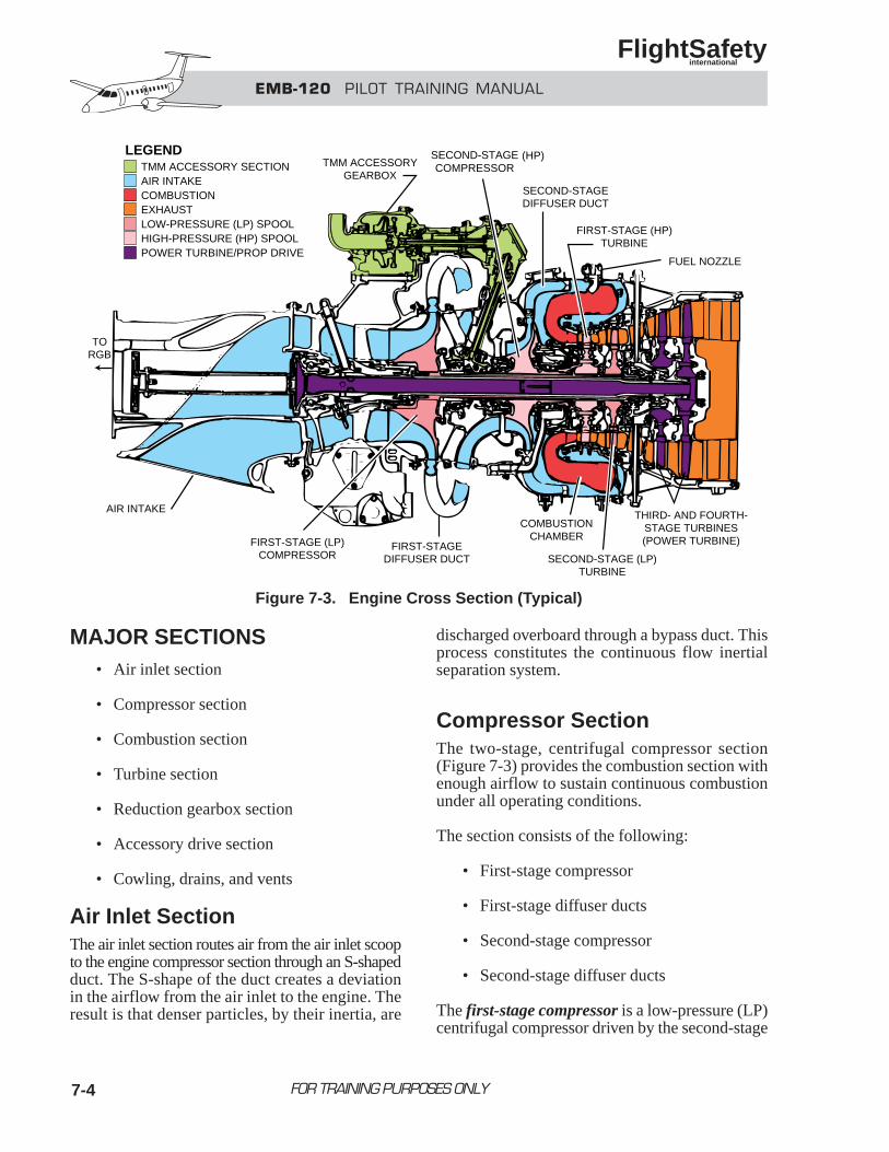
7-4
MAJOR SECTIONS• Air inlet section
• Compressor section
• Combustion section
• Turbine section
• Reduction gearbox section
• Accessory drive section
• Cowling, drains, and vents
Air Inlet SectionThe air inlet section routes air from the air inlet scoopto the engine compressor section through an S-shapedduct. The S-shape of the duct creates a deviationin the airflow from the air inlet to the engine. Theresult is that denser particles, by their inertia, are
discharged overboard through a bypass duct. Thisprocess constitutes the continuous flow inertialseparation system.
Compressor SectionThe two-stage, centrifugal compressor section(Figure 7-3) provides the combustion section withenough airflow to sustain continuous combustionunder all operating conditions.
The section consists of the following:
• First-stage compressor
• First-stage diffuser ducts
• Second-stage compressor
• Second-stage diffuser ducts
The first-stage compressor is a low-pressure (LP)centrifugal compressor driven by the second-stage
FOR TRAINING PURPOSES ONLY
EMB-120 PILOT TRAINING MANUAL
FlightSafety international
TMM ACCESSORYGEARBOX
SECOND-STAGECOMPRESSOR
SECOND-STAGEDIFFUSER DUCT
FIRST-STAGE (HP)TURBINE
FUEL NOZZLE
THIRD- AND FOURTH-STAGE TURBINES(POWER TURBINE)
SECOND-STAGE (LP)TURBINE
COMBUSTIONCHAMBER
FIRST-STAGEDIFFUSER DUCT
FIRST-STAGE (LP)COMPRESSOR
AIR INTAKE
TORGB
TMM ACCESSORY SECTIONAIR INTAKECOMBUSTIONEXHAUSTLOW-PRESSURE (LP) SPOOLHIGH-PRESSURE (HP) SPOOLPOWER TURBINE/PROP DRIVE
LEGEND (HP)
Figure 7-3. Engine Cross Section (Typical)
EMB-120 PILOT TRAINING MANUAL
FlightSafety international
7-5
turbine. It rotates counterclockwise (as viewedfrom the rear).
The LP compressor receives airflow from the air inletsection into the center of the rotating LP impeller.Through centrifugal force, the air is figuratively“thrown” outward and away from center into adecreased space, where it is compressed and rout-ed through the external first-stage diffuser ducts tothe next compression stage.
The second-stage compressor is a high-pressure (HP)centrifugal compressor driven by the first stageturbine. Its clockwise rotation is opposite to the firststage (LP) compressor.
The HP compressor receives airflow from the firststage diffuser ducts into the center of the rotatingHP impeller. It is compressed and routed, throughthe internal second-stage diffuser ducts, to thecombustion chamber.
Combustion SectionThe combustion section is made up of a case whichincludes:
• Combustion chamber
• Fuel nozzles
• Igniter plugs
Air enters the annular, reverse-flow combustion cham-ber via the second-stage diffuser ducts. The direc-tion of the entering airflow is changed 180° toallow for an overall shorter engine length.
Fuel for combustion, supplied by the engine fuel sys-tem, is injected into the annular chamber properlyatomized by 14 fuel nozzles. The fuel/air mixtureis then ignited by two spark igniter plugs.
Turbine SectionThe four-stage, axial flow turbine section convertsthe energy of the expanding gases exiting the com-bustion chamber into rotational force used to drivethe compressors, propeller, and accessories.
The following components make up the turbine section:
• First-stage turbine
• Second-stage turbine
• Third- and fourth-stage turbines
• Thermocouples
The first-stage turbine drives the HP compressorand TMM accessory gearbox. The turbine andcompressor together make up the HP spool.
The second-stage turbine drives the LP compres-sor. The turbine and compressor together make upthe LP spool.
The interconnected third- and fourth-stage tur-bines, or power turbine, drive the RGB, RGBaccessories, and propeller. The power tur-bine rotates in the same direction, clockwise,as the high-pressure spool.
Nine bimetallic thermocouple probes project intothe expanding gases between the second-stage tur-bine and the power turbine to monitor inter-stageturbine (T6) temperature.
The thermocouples are connected in parallelso that output voltage, sent to the respectiveT6 indicator, is proportional to the average tur-bine temperature.
Reduction Gearbox SectionThe RGB is located in front of the TMM abovethe engine air inlet. It reduces the rpm from thepower turbine shaft by a ratio of approximately15:1, and increases the torque delivered to the propeller.
Accessory Drive Sections The engine has two accessory drive sections, oneon the TMM and the other on the RGB.
FOR TRAINING PURPOSES ONLY
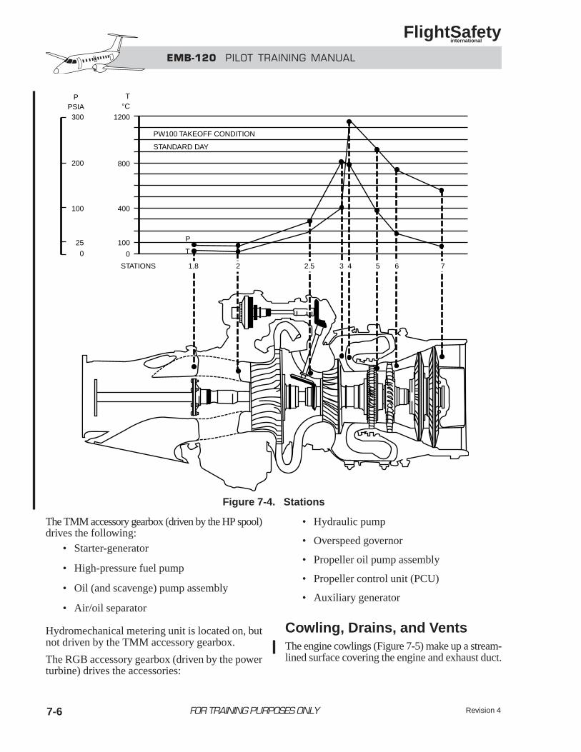
EMB-120 PILOT TRAINING MANUAL
FlightSafety international
7-6
The TMM accessory gearbox (driven by the HP spool)drives the following:
• Starter-generator
• High-pressure fuel pump
• Oil (and scavenge) pump assembly
• Air/oil separator
Hydromechanical metering unit is located on, butnot driven by the TMM accessory gearbox.
The RGB accessory gearbox (driven by the powerturbine) drives the accessories:
• Hydraulic pump
• Overspeed governor
• Propeller oil pump assembly
• Propeller control unit (PCU)
• Auxiliary generator
Cowling, Drains, and Vents The engine cowlings (Figure 7-5) make up a stream-lined surface covering the engine and exhaust duct.
FOR TRAINING PURPOSES ONLY Revision 4
1.8
200
100
25
0
300PSIA
P
1200
°C
PW100 TAKEOFF CONDITION
STANDARD DAY
STATIONS
T
P
T
800
400
100
0
2 2.5 3 4 5 6 7
Figure 7-4. Stations
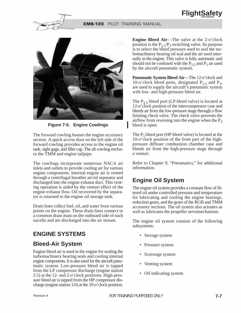
EMB-120 PILOT TRAINING MANUAL
FlightSafety international
Revision 4 7-7
The forward cowling houses the engine accessorysection. A quick access door on the left side of theforward cowling provides access to the engine oiltank, sight gage, and filler cap. The aft cowling enclos-es the TMM and engine tailpipe.
The cowlings incorporate numerous NACA airinlets and outlets to provide cooling air for variousengine components. Internal engine air is ventedthrough a centrifugal breather air/oil separator anddischarged into the engine exhaust duct. This vent-ing operation is aided by the venturi effect of theengine exhaust flow. Oil recovered by the separa-tor is returned to the engine oil storage tank.
Drain lines collect fuel, oil, and water from variouspoints on the engine. These drain lines connect toa common drain mast on the outboard side of eachnacelle and are discharged into the air stream.
ENGINE SYSTEMS
Bleed-Air SystemEngine bleed air is used in the engine for sealing theturbomachinery bearing seals and cooling internalengine components. It is also used for the aircraft pneu-matic system. Low-pressure bleed air is tappedfrom the LP compressor discharge (engine station2.5) at the 12- and 2-o’clock positions. High-pres-sure bleed air is tapped from the HP compressor dis-charge (engine station 3.0) at the 10-o’clock position.
Engine Bleed Air—The valve at the 2-o’clockposition is the P2.5/P3 switching valve. Its purposeis to select the bleed pressure used to seal the tur-bomachinery bearing oil seal and the air used inter-nally in the engine. This valve is fully automatic andshould not be confused with the P2.5 and P3 air usedby the aircraft pneumatic system.
Pneumatic System Bleed Air—The 12-o’clock and10-o’clock bleed ports, designated P2.5 and P3,are used to supply the aircraft’s pneumatic systemwith low- and high-pressure bleed air.
The P2.5 bleed port (LP bleed valve) is located at12-o’clock position of the intercompressor case andbleeds air from the low-pressure stage through a flowlimiting check valve. The check valve prevents theairflow from reversing into the engine when the P3bleed is open.
The P3 bleed port (HP bleed valve) is located at the10-o’clock position of the front part of the high-pressure diffuser combustion chamber case andbleeds air from the high-pressure stage througha venturi.
Refer to Chapter 9, “Pneumatics,” for additionalinformation.
Engine Oil SystemThe engine oil system provides a constant flow of fil-tered oil under controlled pressure and temperaturefor lubricating and cooling the engine bearings,reduction gears, and the gears of the RGB and TMMaccessory sections. The oil system also actuates aswell as lubricates the propeller servomechanism.
The engine oil system consists of the followingsubsystems:
• Storage system
• Pressure system
• Scavenge system
• Venting system
• Oil indicating system
FOR TRAINING PURPOSES ONLY
Figure 7-5. Engine Cowlings
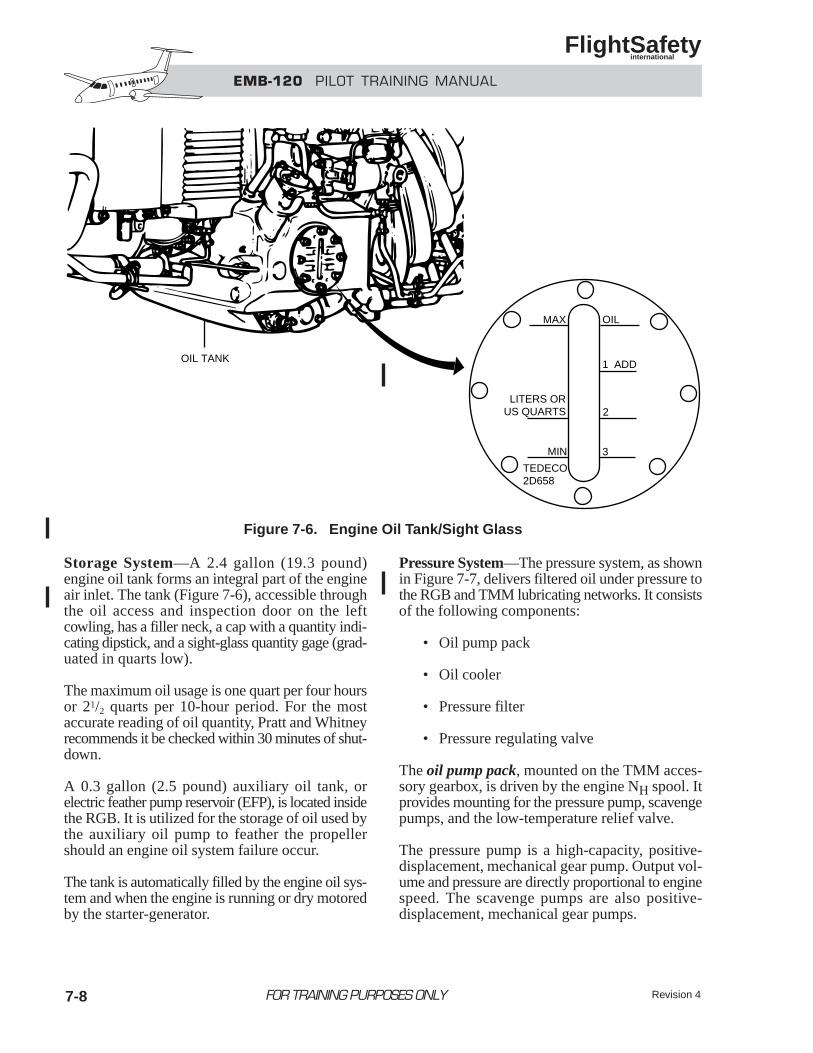
Storage System—A 2.4 gallon (19.3 pound)engine oil tank forms an integral part of the engineair inlet. The tank (Figure 7-6), accessible throughthe oil access and inspection door on the leftcowling, has a filler neck, a cap with a quantity indi-cating dipstick, and a sight-glass quantity gage (grad-uated in quarts low).
The maximum oil usage is one quart per four hoursor 21/2 quarts per 10-hour period. For the mostaccurate reading of oil quantity, Pratt and Whitneyrecommends it be checked within 30 minutes of shut-down.
A 0.3 gallon (2.5 pound) auxiliary oil tank, orelectric feather pump reservoir (EFP), is located insidethe RGB. It is utilized for the storage of oil used bythe auxiliary oil pump to feather the propellershould an engine oil system failure occur.
The tank is automatically filled by the engine oil sys-tem and when the engine is running or dry motoredby the starter-generator.
Pressure System—The pressure system, as shownin Figure 7-7, delivers filtered oil under pressure tothe RGB and TMM lubricating networks. It consistsof the following components:
• Oil pump pack
• Oil cooler
• Pressure filter
• Pressure regulating valve
The oil pump pack, mounted on the TMM acces-sory gearbox, is driven by the engine NH spool. Itprovides mounting for the pressure pump, scavengepumps, and the low-temperature relief valve.
The pressure pump is a high-capacity, positive-displacement, mechanical gear pump. Output vol-ume and pressure are directly proportional to enginespeed. The scavenge pumps are also positive-displacement, mechanical gear pumps.
7-8 FOR TRAINING PURPOSES ONLY
EMB-120 PILOT TRAINING MANUAL
FlightSafety international
Revision 4
MAX OIL
LITERS ORUS QUARTS
1 ADD
2
3MIN
TEDECO2D658
OIL TANK
Figure 7-6. Engine Oil Tank/Sight Glass
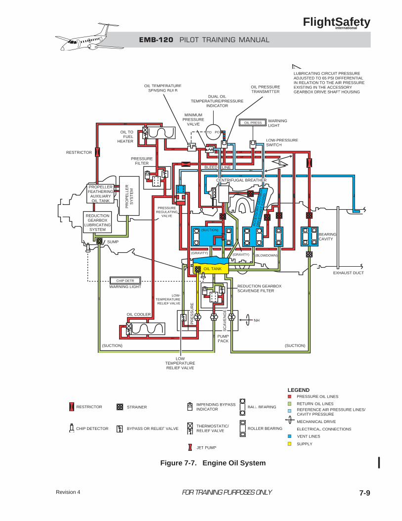
EMB-120 PILOT TRAINING MANUAL
FlightSafety international
7-9FOR TRAINING PURPOSES ONLYRevision 4
1
1
OIL TEMPERATURESENSING BULB
DUAL OILTEMPERATURE/PRESSURE
INDICATOR
TO PO
OIL PRESS
OIL PRESSURETRANSMITTER
WARNINGLIGHT
LOW-PRESSURESWITCH
MINIMUMPRESSURE
VALVE
LUBRICATING CIRCUIT PRESSUREADJUSTED TO 65 PSI DIFFERENTIALIN RELATION TO THE AIR PRESSUREEXISTING IN THE ACCESSORYGEARBOX DRIVE SHAFT HOUSING
OIL TOFUEL
HEATER
PRESSUREFILTER
RESTRICTOR
PROPELLERFEATHERING
AUXILIARYOIL TANK
PR
OP
ELL
ER
SY
ST
EM
REDUCTIONGEARBOX
LUBRICATINGSYSTEM
SUMP
OIL TANK
(GRAVITY) (GRAVITY) (BLOWDOWN)
REDUCTION GEARBOXSCAVENGE FILTER
NH
PUMPPACK
SC
AV
EN
GE
PR
ES
SU
RE
LOWTEMPERATURERELIEF VALVE
OIL COOLER
(SUCTION) (SUCTION)
EXHAUST DUCT
BEARINGCAVITY
CENTRIFUGAL BREATHER
AC
CE
SS
OR
Y G
EA
RB
OX
DR
IVE
SH
AF
T C
AS
ING
(SUCTION)
RESTRICTOR
CHIP DETECTOR
STRAINER
BYPASS OR RELIEF VALVE
IMPENDING BYPASSINDICATOR
THERMOSTATIC/RELIEF VALVE
JET PUMP
BALL BEARING
ROLLER BEARING
OIL LINES
OIL LINES
PRESSURE
RETURN
REFERENCE AIR PRESSURE LINES/CAVITY PRESSURE
MECHANICAL DRIVE
ELECTRICAL CONNECTIONS
VENT LINES
SUPPLY
CHIP DETR
PRESSUREREGULATING
VALVE
WARNING LIGHT
LOW-TEMPERATURERELIEF VALVE
LEGEND
BLEED LINE
Figure 7-7. Engine Oil System
EMB-120 PILOT TRAINING MANUAL
FlightSafety international
Revision 47-10 FOR TRAINING PURPOSES ONLY
The oil pressure system components are protectedduring engine start by the low-temperature relief valve.The valve prevents the oil pump discharge pressurefrom exceeding 210 psi by returning part of the oilto the engine oil tank.
The oil cooler is an oil-to-air heat exchanger locat-ed in a separate duct below the engine intake duct.
The flow of oil through the oil cooler is controlledby a thermostatic/bypass valve. The valve maintainsoil temperature within the normal operating range,and also opens to bypass oil when the pressure dif-ferential between the oil cooler inlet and outletexceeds a preset limit.
NOTEExtended ground operation in feather orground idle reduces airflow to the oil cool-er, resulting in high oil temperatures.
The pressure filter is located on the left side of theengine above the oil sight glass. It includes a bypassvalve that opens when pressure differential acrossthe filter exceeds 20 psid.
The pressure regulating valve maintains a con-stant differential between the oil pressure in the num-ber 6 and 7 bearing cavities and the air pressure inthe TMM accessory section gear cavity. The excessoil pressure is returned to the oil pump.
Scavenge System—There are two oil scavengesystems: one for the TMM lubricating network, andone for the RGB lubricating network.
The TMM scavenge system returns oil to theengine oil tank through internal passages andexternal tubing.
Oil from the number 1 and 2 bearings is returnedby both gravity draining and an ejector jet pump.
Oil from the number 3, 4, and 5 bearing cavitiesis returned using the air pressure from labyrinthseal leakage.
Oil from the number 6 and 7 bearing cavities isreturned by a scavenge pump mounted on the oilpump pack.
The RGB scavenge system includes a positive-displacement, mechanical gear pump mounted onthe oil pump pack, and a scavenge filter. The filterincorporates a bypass valve in the event of clogging.
Venting System—The engine oil system uses a cen-trifugal breather to separate oil from the internal engineair before venting overboard.
The centrifugal breather is inside the TMM acces-sory gearbox. Oil separated by centrifugal force isreturned to the engine oil storage tank while the airis vented overboard through external tubes along theright side of the engine into the engine exhaust duct.The venturi effect of the engine exhaust gas flow assiststhe venting.
Oil Indicating System—The oil indicating sys-tem provides a visual indication of the oil pressureand temperature measured in the TMM, and mag-netic chip detection in the oil tank and RGBsump. It includes the following components andsubsystems:
• Temperature/pressure indicator
• Temperature sensing bulb
• Pressure transmitter
• Low-pressure warning system
• Magnetic chip detection warning system
A combined oil temperature/pressure indicator foreach engine is installed on the cockpit main instru-ment panel. They are back-lighted, dual analogpointer displays with the oil temperature on the leftscale and oil pressure on the right.
The indicators are powered by 28 VDC, and 5 VDCfor lighting. They include a circuit that drives theindicators off scale in the event of a power loss.
An oil temperature bulb senses the temperature ofthe oil downstream of the fuel heater and sends itto the temperature/pressure indicator.
An oil pressure transmitter provides input to the pres-sure side of the oil temperature/pressure indicator.
EMB-120 PILOT TRAINING MANUAL
FlightSafety international
Revision 4 7-11FOR TRAINING PURPOSES ONLY
The transmitter is connected to the oil system bytwo lines. One line provides total oil pressureinput and the other provides TMM accessory gearcavity air pressure.
The transmitter converts the reference oil and air pres-sures into differential oil pressure and sends it to thetemperature/pressure indicator.
A low oil pressure warning system for each engineprovides a visual and aural warning when the oil pres-sure falls below 40 psid.
When a differential pressure switch connected to theoil system pressure regulating valve is activated at40 psid, an aural alarm of three chimes sounds, andthe red OIL PRESS 1 or OIL PRESS 2 light on theMAP flashes. The voice warning “OIL” is given andthe master WARNING lights flash. The low oil pres-sure warning is inhibited during engine start and inten-tional engine shutdown.
NOTEThe engine low oil pressure switch isalso utilized to prevent overheat damageto the propeller blades by the electrical deic-ing circuit. The propeller blades may beheated only when the oil pressure isabove 40 psid.
Engine operation with oil pressure between40 and 55 psid is permitted only if the NHis below 75%.
Oil pressure below 40 psid requiresengine shutdown.
The magnetic chip detection system provides anindication of the presence of metal particles inthe oil. The magnetic chip detectors are installedin the reduction gearbox and the engine oil tank.If a chip is detected, the system provides a visualalert to maintenance personnel by illumination ofan amber CHIP DET 1 or CHIP DET 2 light locat-ed in the battery compartment.
NOTEChip detector lights on some unmodifiedaircraft are installed on the MAP andsound an aural alert.
Engine Fuel SystemThe engine fuel system receives fuel from the air-plane’s fuel tanks and delivers it to the combustionsection with enough fuel flow to sustain continuouscombustion under all operating conditions. Fordescription of components prior to the HMU, seeChapter 5, “Fuel System”.
Hydromechanical Metering Unit (HMU)—TheHMU (Figure 7-8) is the engine fuel control unit.It is mounted on the forward end of the engine fuelpump (which is located on, and driven by, theTMM accessories section). The HMU controls theminimum and maximum limits of fuel flow to theengine as a function of the power lever angle (PLA)and high-pressure compressor discharge pressure(P3). It also provides the motive fuel flow to oper-ate the fuel tank ejector jet pumps.
The motive flow valve allows fuel in excess of theengine requirements to return to the fuel tank, sup-plying motive-flow pressure to operate the tank ejec-tor jet pumps.
Pressure relief and regulating valves maintain thenecessary pressure differential within the HMUby diverting part of the fuel flow to the ejector jetpump in the engine fuel pump.
A power lever valve, actuated by the power lever,determines the rate of fuel flow. A potentiometer,located at the bottom of the power lever valve shaft,provides the engine electronic control (EEC) withan electrical signal proportional to the power leverangle. This signal is used by the EEC in modifyingthe HMU fuel schedule supplied to the engine.
A P3 sensor and servo, utilizing engine bleed air,works in conjunction with the power lever valve todetermine the basic fuel flow schedule to theengine. It varies the fuel flow to the engine basedon the HP compressor discharge pressure.
Signals from the EEC to a torque motor operate avalve that modifies the basic fuel scheduled bythe power lever valve and P3 servo position.
A deenrichment solenoid valve, electrically con-trolled by the EEC, prevents engine compressorstalling associated with high-altitude power levertransients. The solenoid is energized above 14,000
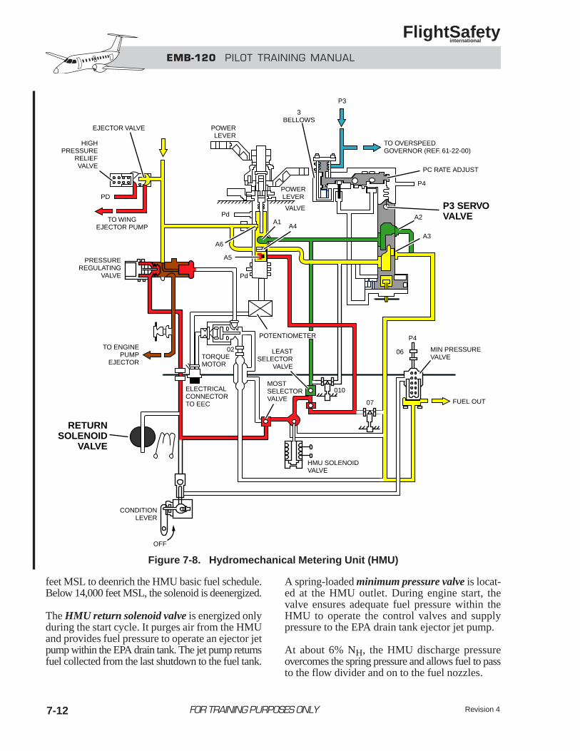
EMB-120 PILOT TRAINING MANUAL
FlightSafety international
Revision 47-12 FOR TRAINING PURPOSES ONLY
feet MSL to deenrich the HMU basic fuel schedule.Below 14,000 feet MSL, the solenoid is deenergized.
The HMU return solenoid valve is energized onlyduring the start cycle. It purges air from the HMUand provides fuel pressure to operate an ejector jetpump within the EPA drain tank. The jet pump returnsfuel collected from the last shutdown to the fuel tank.
A spring-loaded minimum pressure valve is locat-ed at the HMU outlet. During engine start, thevalve ensures adequate fuel pressure within theHMU to operate the control valves and supplypressure to the EPA drain tank ejector jet pump.
At about 6% NH, the HMU discharge pressureovercomes the spring pressure and allows fuel to passto the flow divider and on to the fuel nozzles.
EJECTOR VALVE
HIGHPRESSURE
RELIEFVALVE
POWERLEVER
3BELLOWS
P3
PdA1
A4
A6
A5
Pd
POWERLEVER
VALVE
TO WINGEJECTOR PUMP
PD
PRESSUREREGULATING
VALVE
TO ENGINEPUMP
EJECTOR
RETURNSOLENOID
VALVE
CONDITIONLEVER
OFF
HMU SOLENOIDVALVE
ELECTRICALCONNECTORTO EEC
TORQUEMOTOR
02
POTENTIOMETER
LEASTSELECTOR
VALVE
MOSTSELECTORVALVE
010
07
06
P4
MIN PRESSUREVALVE
FUEL OUT
A2
A3
P3 SERVOVALVE
P4
PC RATE ADJUST
TO OVERSPEEDGOVERNOR (REF. 61-22-00)
Figure 7-8. Hydromechanical Metering Unit (HMU)
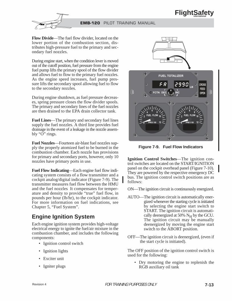
EMB-120 PILOT TRAINING MANUAL
FlightSafety international
Revision 4 7-13FOR TRAINING PURPOSES ONLY
Flow Divide—The fuel flow divider, located on thelower portion of the combustion section, dis-tributes high-pressure fuel to the primary and sec-ondary fuel nozzles.
During engine start, when the condition lever is movedout of the cutoff position, fuel pressure from the enginefuel pump lifts the primary spool of the flow dividerand allows fuel to flow to the primary fuel nozzles.As the engine speed increases, fuel pump pres-sure lifts the secondary spool allowing fuel to flowto the secondary nozzles.
During engine shutdown, as fuel pressure decreas-es, spring pressure closes the flow divider spools.The primary and secondary lines of the fuel nozzlesare then drained to the EPA drain collector tank.
Fuel Lines—The primary and secondary fuel linessupply the fuel nozzles. A third line provides fueldrainage in the event of a leakage in the nozzle assem-bly “O” rings.
Fuel Nozzles—Fourteen air-blast fuel nozzles sup-ply the properly atomized fuel to be burned in thecombustion chamber. Each nozzle has provisionsfor primary and secondary ports, however, only 10nozzles have primary ports in use.
Fuel Flow Indicating—Each engine fuel flow indi-cating system consists of a flow transmitter and acockpit analog/digital indicator (Figure 7-9). Thetransmitter measures fuel flow between the HMUand the fuel nozzles It compensates for temper-ature and density to provide “true” fuel flow, inpounds per hour (lb/hr), to the cockpit indicator.For more information on fuel indications, seeChapter 5, “Fuel System”.
Engine Ignition SystemEach engine ignition system provides high-voltageelectrical energy to ignite the fuel/air mixture in thecombustion chamber, and includes the followingcomponents:
• Ignition control switch
• Ignition lights
• Exciter unit
• Igniter plugs
Ignition Control Switches—The ignition con-trol switches are located on the START/IGNITIONpanel on the cockpit overhead panel (Figure 7-10).They are powered by the respective emergency DCbus. The ignition control switch positions are asfollows:
ON—The ignition circuit is continuously energized.
AUTO—The ignition circuit is automatically ener-gized whenever the starting cycle is initiatedby selecting the engine start switch toSTART. The ignition circuit is automati-cally deenergized at 50% NH by the GCU.The ignition circuit may be manuallydeenergized by moving the engine startswitch to the ABORT position.
OFF—The ignition circuit is deenergized, (even ifthe start cycle is initiated).
The OFF position of the ignition control switch isused for the following:
• Dry motoring the engine to replenish theRGB auxiliary oil tank
Figure 7-9. Fuel Flow Indicators
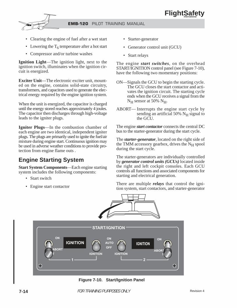
EMB-120 PILOT TRAINING MANUAL
FlightSafety international
Revision 47-14 FOR TRAINING PURPOSES ONLY
• Clearing the engine of fuel after a wet start
• Lowering the T6 temperature after a hot start
• Compressor and/or turbine washes
Ignition Light—The ignition light, next to theignition switch, illuminates when the ignition cir-cuit is energized.
Exciter Unit—The electronic exciter unit, mount-ed on the engine, contains solid-state circuitry,transformers, and capacitors used to generate the elec-trical energy required by the engine ignition system.
When the unit is energized, the capacitor is chargeduntil the energy stored reaches approximately 4 joules.The capacitor then discharges through high-voltageleads to the igniter plugs.
Igniter Plugs—In the combustion chamber ofeach engine are two identical, independent igniterplugs. The plugs are primarily used to ignite the fuel/airmixture during engine start. Continuous ignition maybe used in adverse weather conditions to provide pro-tection from engine flame outs .
Engine Starting SystemStart System Components—Each engine startingsystem includes the following components:
• Start switch
• Engine start contactor
• Starter-generator
• Generator control unit (GCU)
• Start relays
The engine start switches, on the overheadSTART/IGNITION control panel (see Figure 7-10),have the following two momentary positions:
ON—Signals the GCU to begin the starting cycle.The GCU closes the start contactor and acti-vates the ignition circuit. The starting cycleends when the GCU receives a signal from theNH sensor at 50% NH.
ABORT— Interrupts the engine start cycle bysending an artificial 50% NH signal tothe GCU.
The engine start contactor connects the central DCbus to the starter-generator during the start cycle.
The starter-generator, located on the right side ofthe TMM accessory gearbox, drives the NH spoolduring the start cycle.
The starter-generators are individually controlledby generator control units (GCUs) located insidethe right and left cockpit consoles. Each GCUcontrols all functions and associated components forstarting and electrical generation.
There are multiple relays that control the igni-tion system, start contactors, and starter-generator
Figure 7-10. Start/Ignition Panel
EMB-120 PILOT TRAINING MANUAL
FlightSafety international
Revision 4 7-15FOR TRAINING PURPOSES ONLY
operation, as well as protect against starter-generatorshort circuits, and prevent simultaneous starting ofboth engines.
The relays are in the respective DC relay box andoperated by the GCUs.
Starting System Operation—The engine startingcycle is an automatic sequence in which the igni-tion and starting systems are simultaneously acti-vated and deactivated.
The electrical power for engine starting may be froman external power source or the airplane battery.
The APU generator, or the generator of the otherengine, may be used to assist the battery during anengine start. The output of a generator alone is notsufficient to provide the power required for anengine start.
During this description of starting system operation,the following prestart configuration is assumed:
• Power select switch —EXTernal
• Generator switches—OFF
• Bus tie switches—ON
• Fuel boost pump —ON
• Power levers—GROUND IDLE
• Condition levers—FUEL CUTOFF
• Ignition switches—AUTO
Momentarily placing the starting switch to the ONposition sends a signal to the GCU that initiates thefollowing start sequence:
• The ignition circuit is energized (white IGNI-TION light illuminates).
• The start contactor connects the available poweron the central DC bus to the starter-genera-tor, which drives the NH spool assembly.
• When NH reaches 10%, the pilot moves thecondition lever from the CUT-OFF to theFEATHER position, introducing fuel into theengine.
• The HMU return solenoid valve, energizedby the GCU, purges air from the HMU andthe empties the EPA drain collector tankinto the respective wing fuel tank.
• The HMU provides fuel through the flow-divider primary fuel nozzles to the combus-tion chamber. The secondary fuel nozzlesactivate later in the start cycle when fuelpressure is higher.
• The igniter plugs ignite the fuel/air mix-ture, as indicated by a T6 rise in approximatelyfive seconds (maximum 10 seconds).
NOTET6 should be monitored for a hot start asthe HP spool continues to accelerate.
• When NH reaches 50%, the starter-genera-tor signals the GCU to terminate the start cycle(white IGNITION light goes out).
• The GCU opens the start contactor, turns offthe ignition circuit, deenergizes the HMUsolenoid, and enables the generator functionof the starter-generator. At this point, theengine is self-sustaining and will continueto accelerate to approximately 62% NHand stabilize.
Hot Start Indication—If the T6 is rising rapidlywith a relatively slow NH acceleration, an imminenthot start is indicated. The condition lever should bemoved to FUEL CUTOFF and, at the end of the 30-second starter limit, the START switch should bemoved to ABORT. The cause of the hot start shouldbe investigated before another start is attempted.
Wet Start Indication—If no T6 rise is observed,and NH stagnates or stabilizes below 50% NH, it maybe assumed that the engine has failed to light-off anda probable wet start has occurred.
In this case, the condition lever should be moved toFUEL CUTOFF and the IGNITION switch movedto OFF. At the end of the 30-second starter limit, theSTART switch should be moved to ABORT.
The cause of the wet start should be investigated beforeanother start is attempted.
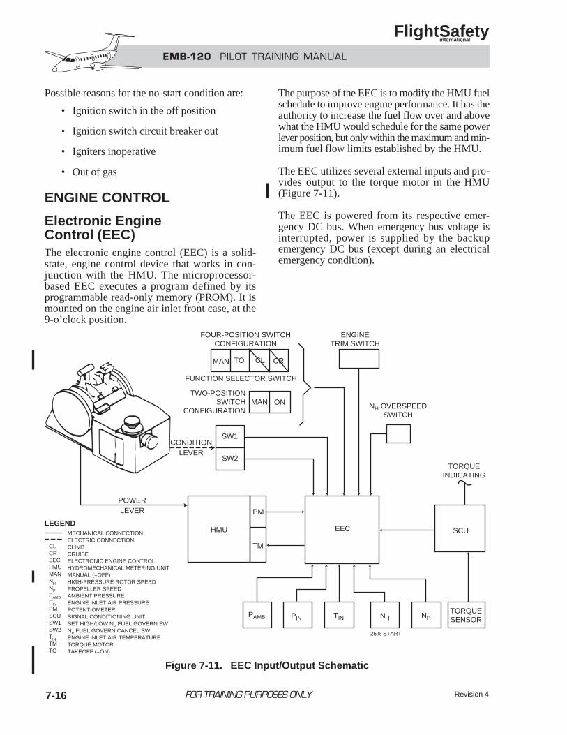
EMB-120 PILOT TRAINING MANUAL
FlightSafety international
Revision 47-16 FOR TRAINING PURPOSES ONLY
Possible reasons for the no-start condition are:
• Ignition switch in the off position
• Ignition switch circuit breaker out
• Igniters inoperative
• Out of gas
ENGINE CONTROL
Electronic EngineControl (EEC)The electronic engine control (EEC) is a solid-state, engine control device that works in con-junction with the HMU. The microprocessor-based EEC executes a program defined by itsprogrammable read-only memory (PROM). It ismounted on the engine air inlet front case, at the9-o’clock position.
The purpose of the EEC is to modify the HMU fuelschedule to improve engine performance. It has theauthority to increase the fuel flow over and abovewhat the HMU would schedule for the same powerlever position, but only within the maximum and min-imum fuel flow limits established by the HMU.
The EEC utilizes several external inputs and pro-vides output to the torque motor in the HMU(Figure 7-11).
The EEC is powered from its respective emer-gency DC bus. When emergency bus voltage isinterrupted, power is supplied by the backupemergency DC bus (except during an electricalemergency condition).
FOUR-POSITION SWITCHCONFIGURATION
ENGINETRIM SWITCH
NH OVERSPEEDSWITCH
TORQUEINDICATING
CONDITIONLEVER
POWERLEVER
FUNCTION SELECTOR SWITCH
TWO-POSITIONSWITCH
CONFIGURATION
MAN TO CL CR
MAN ON
SW1
SW2
EEC SCU
PM
TM
HMU
PAMB PIN TIN NH NPTORQUESENSOR
MECHANICAL CONNECTIONELECTRIC CONNECTIONCLIMBCRUISEELECTRONIC ENGINE CONTROLHYDROMECHANICAL METERING UNITMANUAL (=OFF)HIGH-PRESSURE ROTOR SPEEDPROPELLER SPEEDAMBIENT PRESSUREENGINE INLET AIR PRESSUREPOTENTIOMETERSIGNAL CONDITIONING UNITSET HIGH/LOW NP FUEL GOVERN SWNP FUEL GOVERN CANCEL SWENGINE INLET AIR TEMPERATURETORQUE MOTORTAKEOFF (=ON)
CLCREECHMUMANNHNPPAMBPINPMSCUSW1SW2TINTMTO
LEGEND
25% START
Figure 7-11. EEC Input/Output Schematic
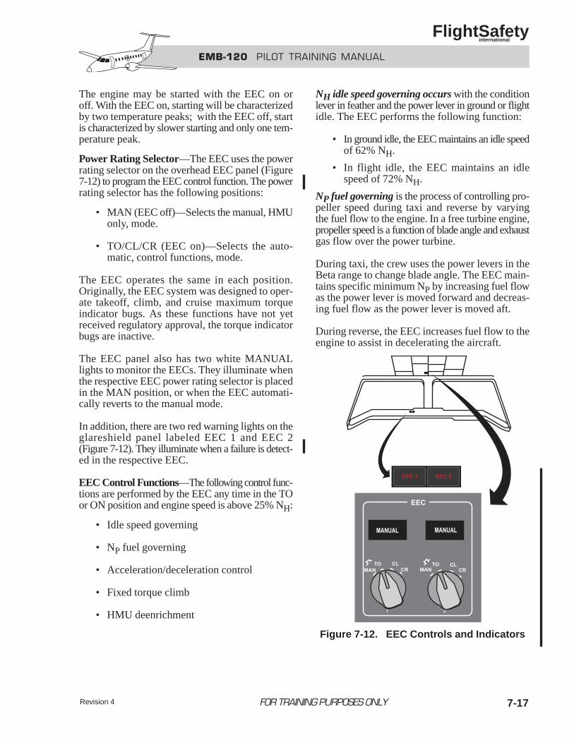
EMB-120 PILOT TRAINING MANUAL
FlightSafety international
Revision 4 7-17FOR TRAINING PURPOSES ONLY
The engine may be started with the EEC on oroff. With the EEC on, starting will be characterizedby two temperature peaks; with the EEC off, startis characterized by slower starting and only one tem-perature peak.
Power Rating Selector—The EEC uses the powerrating selector on the overhead EEC panel (Figure7-12) to program the EEC control function. The powerrating selector has the following positions:
• MAN (EEC off)—Selects the manual, HMUonly, mode.
• TO/CL/CR (EEC on)—Selects the auto-matic, control functions, mode.
The EEC operates the same in each position.Originally, the EEC system was designed to oper-ate takeoff, climb, and cruise maximum torqueindicator bugs. As these functions have not yetreceived regulatory approval, the torque indicatorbugs are inactive.
The EEC panel also has two white MANUALlights to monitor the EECs. They illuminate whenthe respective EEC power rating selector is placedin the MAN position, or when the EEC automati-cally reverts to the manual mode.
In addition, there are two red warning lights on theglareshield panel labeled EEC 1 and EEC 2(Figure 7-12). They illuminate when a failure is detect-ed in the respective EEC.
EEC Control Functions—The following control func-tions are performed by the EEC any time in the TOor ON position and engine speed is above 25% NH:
• Idle speed governing
• NP fuel governing
• Acceleration/deceleration control
• Fixed torque climb
• HMU deenrichment
NH idle speed governing occurs with the conditionlever in feather and the power lever in ground or flightidle. The EEC performs the following function:
• In ground idle, the EEC maintains an idle speedof 62% NH.
• In flight idle, the EEC maintains an idlespeed of 72% NH.
NP fuel governing is the process of controlling pro-peller speed during taxi and reverse by varyingthe fuel flow to the engine. In a free turbine engine,propeller speed is a function of blade angle and exhaustgas flow over the power turbine.
During taxi, the crew uses the power levers in theBeta range to change blade angle. The EEC main-tains specific minimum NP by increasing fuel flowas the power lever is moved forward and decreas-ing fuel flow as the power lever is moved aft.
During reverse, the EEC increases fuel flow to theengine to assist in decelerating the aircraft.
Figure 7-12. EEC Controls and Indicators
EMB-120 PILOT TRAINING MANUAL
FlightSafety international
Revision 47-18 FOR TRAINING PURPOSES ONLY
With NP fuel governing, the EEC maintains the fol-lowing conditions:
• 50% NP with the condition lever at MINrpm
• 65% NP with the condition levers at MAX rpm
• 80% NP with the power levers in reverse
Without NP fuel governing, the following conditionsexist:
• When the power levers are moved forward,blade angle increases and NP decreases.
• When the power levers are moved aft, bladeangle decreases and NP increases.
• When the power levers are moved intoreverse, no engine spool-up occurs.
NP fuel governing is canceled by the following:
• Condition lever in feather
• Operation of the autofeather system
• Pulling the engine fire handle
The acceleration/deceleration control function ofthe EEC controls the acceleration of the engine toimprove spool-up time and eliminate compressorstalls, and controls the deceleration of the engine,thereby preventing flameouts.
Fixed Torque Climb—In most aircraft to maintainthe same power output during the climb, the crewmust continuously move the power levers forward.
In this aircraft, the EEC fixed-torque climb featuremaintains the selected torque during the climb byincreasing fuel flow to the engine. As a result, theT6 temperature increases and small, occasionalpower lever reductions are necessary to keep the T6temperature within climb limits.
The HMU deenrichment solenoid valve control sys-tem is activated depending upon the altitude ofthe aircraft. The valve is either open or closed.
Under standard sea-level conditions (except forN
Pand NH speed governing functions), the EEC and
the HMU schedule approximately the same fuel flowto the engine at idle.
During climb, the EEC maintains the selected fixedtorque by constantly increasing the fuel flow overand above what the HMU would schedule for thesame power lever position.
At approximately 14,000 feet, the HMU fuel sched-ule has become too rich for the EEC to optimize bythe addition of fuel. Also, at high altitudes with onlythe HMU controlling fuel flow, the engine is sub-ject to compressor stalls on slam accelerations.
The deenrichment solenoid valve control systemincludes the following two altitude switches:
• 14K switch
• 10K switch
The 14K switch:
• Energizes the solenoid when climbing through14,000 feet, closing the valve
• This leans the HMUs fuel schedule to allowthe EEC to control engine acceleration anddeceleration at high altitudes, and preventpower-lever-induced compressor stalls.
• Deenergizes the solenoid when descendingthrough 14,000 feet, opening the valve
• If the HMU deenrichment solenoid failedto deenergize on descent, the HMU fuelschedule would remain lean. Reducing thepower lever to idle could result in engineflame out due to insufficient fuel flow.
The 10K switch: triggers an EEC warning descend-ing through approximately 10,000 feet if the HMUdeenrichment solenoid fails to deenergize
A three-chime aural alert sounds, the red EEC 1 orEEC 2 light on the glareshield panel illuminates, avoice warning “ENGINE CONTROL” is given, andthe master WARNING lights flash.
EMB-120 PILOT TRAINING MANUAL
FlightSafety international
Revision 4 7-19FOR TRAINING PURPOSES ONLY
When this occurs, crew action should be performedas follows:
• Power rating selector MAN
• Refer to checklist
• Maintain torque above 20% with the powerlever
• Make slow power lever movements to mini-mize flame-out possibility (HMU solenoid maybe stuck in the high-altitude, lean position).
HMU Solenoid Test—After engine start or duringtaxi out, the EECs are alternately switched off.Under most conditions, this should cause a slightdrop in fuel flow and, consequently, NH. Howev-er, if the NH drops below 50% or the engine flamesout, the HMU solenoid may be stuck in the ener-gized position. If the problem is verified (by dupli-cating the NH drop when repeating the check withthe bleed OFF), maintenance action is requiredprior to flight.
EEC Failures—When an electrical, sensor, orsoftware malfunction occurs, the system reverts tomanual control (HMU only). Reversion to manu-al control is identified by the following:
• Power loss, recoverable by advancing thepower lever
• Power lever stagger for equivalent torque
• Slower than normal acceleration
• Faster than normal deceleration
• Loss of the fixed torque climb feature
When the EEC provides a signal to revert to the man-ual mode, the following occurs:
• Torque motor is inhibited
• White MANUAL light on the EEC panel illuminates
• Relevant red EEC 1 or EEC 2 light on theglareshield panel illuminates
• Three-chime aural alert sounds, and “ENGINECONTROL” voice warning is given
• Master WARNING lights flash
Fail Fixed—If a peripheral EEC sensor shouldfail the EEC 1 or EEC 2 warnings are generated, butthe EEC will not revert to manual. The EEC torquemotor current is frozen at its present value to pre-vent engine spool backs during takeoff. This iscalled a fail-fixed malfunction and occurs at altitudesless than 14,000 feet.
On aborted takeoffs, this function enhances reversethrust asymmetry. The fail-fixed function is canceledwhen the EEC is reset or turned off.
With the EEC inoperative, consult the approved Air-plane Flight Manual, “Limitations” section, forthe maximum aircraft operating altitude.
EEC Safety Features• NH overspeed protection at 103% (EEC
switches off)
• NH underspeed protection below 60% NH(EEC switches off)
• NP >100% or NP accelerating faster than apredetermined rate, EEC reduces fuel flowto control NP within 106% (feature enabledwhen NP >80%)
Engine Power ControlsEngine power control is accomplished by two pairsof levers that control power output, fuel shutoff, pro-peller pitch and speed, and propeller featheringby mechanical means.
The power levers and condition levers are locatedon the center pedestal console (Figure 7-13).
Power Levers—The power levers are located on theleft side of the console. They are mechanicallyconnected to, and the primary input for, the HMU(Figure 7-14). The power levers are also intercon-nected with the propeller control unit (PCU) for directblade angle control (BETA mode) and electricallyconnected to the EEC.
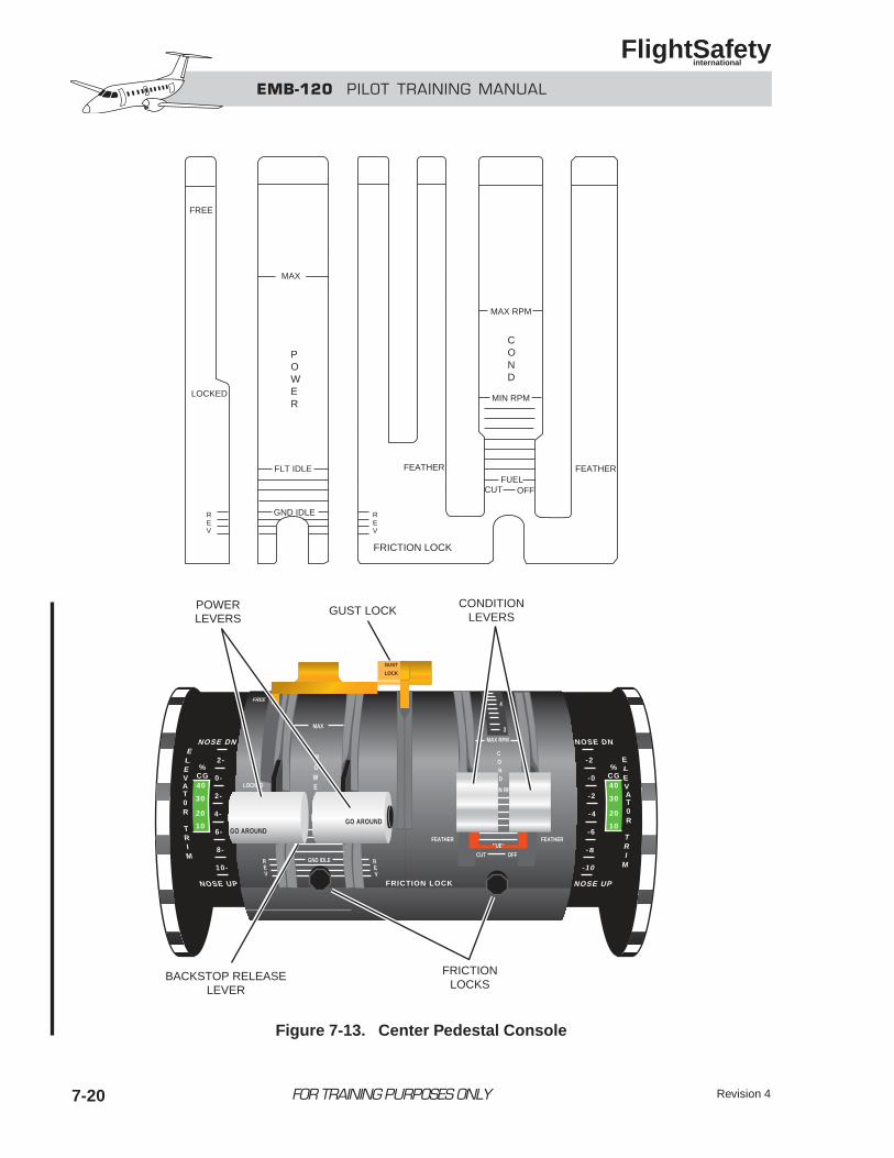
EMB-120 PILOT TRAINING MANUAL
FlightSafety international
Revision 47-20 FOR TRAINING PURPOSES ONLY
FREE
LOCKED
REV
POWER
FLT IDLE
GND IDLE REV
FEATHER
FRICTION LOCK
COND
CUT OFFFUEL
MIN RPM
MAX RPM
FEATHER
CONDITIONLEVERS
POWERLEVERS
MAX
FRICTION LOCK
POW
GND IDLE
LOCKED
FREE
MAX RPM
C O N D
MIN RPM
MAX
FEATHER
CUT OFFFUEL
FEATHER
REV
REV
E
GUST
LOCK
NOSE DN
%CG
2-ELEVAT0R
TRIM
NOSE UP
0-
2-
4-
6-
8-
10-
40
30
20
10
3
4
NOSE DN
NOSE UP
-2
-0
-2
-4
-6
-8
-10
ELEVAT0R
TRI
M
%CG40
30
20
10GO AROUND
GO AROUND
GUST LOCK
FRICTIONLOCKS
BACKSTOP RELEASELEVER
Figure 7-13. Center Pedestal Console
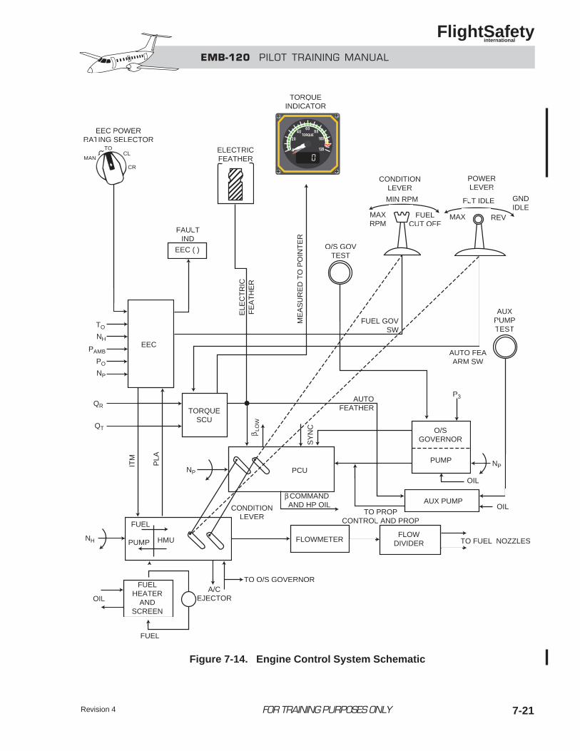
EMB-120 PILOT TRAINING MANUAL
FlightSafety international
Revision 4 7-21FOR TRAINING PURPOSES ONLY
EEC POWERRATING SELECTOR
TORQUEINDICATOR
ELECTRICFEATHERMAN
TOCL
CR
EEC ( )
FAULTIND
EEC
TO
NH
PAMB
PO
NP
ITM
PLA
QR
QT
NH
OIL
FUEL
PUMP HMU
FUELHEATER
ANDSCREEN
A/CEJECTOR
TO O/S GOVERNOR
CONDITIONLEVER
FLOWMETER
β COMMANDAND HP OIL
β LO
W
SY
NC
AUTOFEATHER
PCU
TORQUESCU
O/SGOVERNOR
PUMP
OIL
OIL
NP
P3
AUTO FEAARM SW
AUXPUMPTEST
AUX PUMP
TO FUEL NOZZLESFLOW
DIVIDER
O/S GOVTEST
MAXRPM
FUELCUT OFF
MIN RPM
FUEL GOVSW
CONDITIONLEVER
POWERLEVER
FLT IDLE
MAX REV
GNDIDLE
ME
AS
UR
ED
TO
PO
INT
ER
ELE
CT
RIC
FE
AT
HE
R
FUEL
TO PROPCONTROL AND PROP
NP
Figure 7-14. Engine Control System Schematic
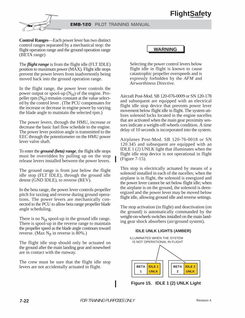
EMB-120 PILOT TRAINING MANUAL
FlightSafety international
Revision 47-22 FOR TRAINING PURPOSES ONLY
Control Ranges—Each power lever has two distinctcontrol ranges separated by a mechanical stop: theflight operation range and the ground operation range(BETA range)
The flight range is from the flight idle (FLT IDLE)position to maximum power (MAX). Flight idle stopsprevent the power levers from inadvertently beingmoved back into the ground operation range.
In the flight range, the power lever controls thepower output or spool-up (NH) of the engine. Pro-peller rpm (NP) remains constant at the value select-ed by the control lever . (The PCU compensates forthe increase or decrease in engine power by varyingthe blade angle to maintain the selected rpm.)
The power levers, through the HMU, increase ordecrease the basic fuel flow schedule to the engine.The power lever position angle is transmitted to theEEC through the potentiometer on the HMU powerlever valve shaft.
To enter the ground (beta) range, the flight idle stopsmust be overridden by pulling up on the stoprelease levers installed between the power levers.
The ground range is from just below the flightidle stop (FLT IDLE), through the ground idledetent (GND IDLE), to reverse (REV).
In the beta range, the power lever controls propellerpitch for taxiing and reverse during ground opera-tions. The power levers are mechanically con-nected to the PCU to allow beta range propeller bladeangle scheduling.
There is no NH spool-up in the ground idle range.There is spool-up in the reverse range to maintainthe propeller speed as the blade angle continues towardreverse. (Max NP in reverse is 80%.)
The flight idle stop should only be actuated onthe ground after the main landing gear and nosewheelare in contact with the runway.
The crew must be sure that the flight idle stoplevers are not accidentally actuated in flight.
Selecting the power control levers belowflight idle in flight is known to causecatastrophic propeller overspeeds and isexpressly forbidden by the AFM andAirworthiness Directive.
Aircraft Post-Mod. SB 120-076-0009 or SN 120-178and subsequent are equipped with an electricalflight idle stop device that prevents power levermovement below flight idle in flight. The system uti-lizes solenoid locks located in the engine nacellesthat are activated when the main gear proximity sen-sors indicate a weight-off-wheels condition. A timedelay of 10 seconds is incorporated into the system.
Airplanes Post-Mod. SB 120-76-0018 or SN120.345 and subsequent are equipped with anIDLE 1 (2) UNLK light that illuminates when theflight idle stop device is not operational in flight (Figure 7-15).
This stop is electrically actuated by means of asolenoid installed in each of the nacelles; when theairplane is in flight, the solenoid is energized andthe power lever cannot be set below flight idle; whenthe airplane is on the ground, the solenoid is deen-ergized and the power lever may be moved belowflight idle, allowing ground idle and reverse settings.
The stop activation (in flight) and deactivation (onthe ground) is automatically commanded by theweight-on-wheels switches installed on the main land-ing gear shock absorbers (air/ground system).
WARNING
BETA
1
IDLE 1
UNLK
BETA
2
IDLE 2
UNLK
IDLE UNLK LIGHTS (AMBER)
ILLUMINATED WHEN THE SYSTEMIS NOT OPERATIONAL IN FLIGHT
Figure 15. IDLE 1 (2) UNLK Light
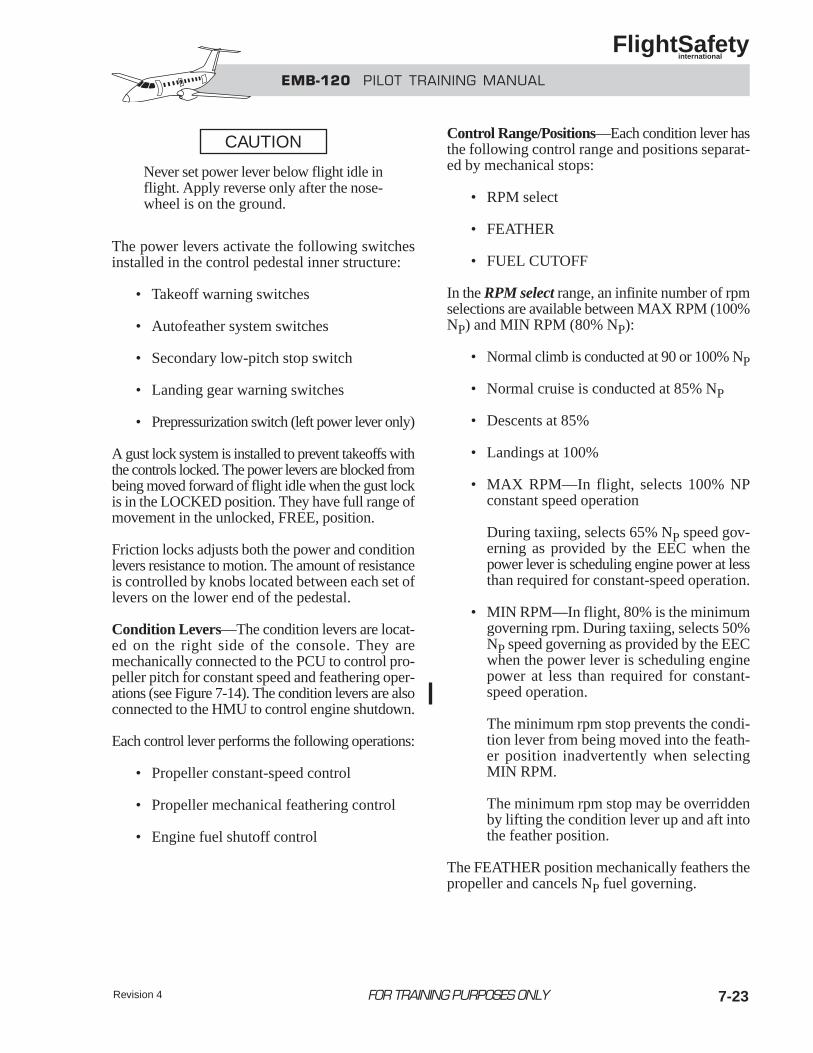
Never set power lever below flight idle inflight. Apply reverse only after the nose-wheel is on the ground.
The power levers activate the following switchesinstalled in the control pedestal inner structure:
• Takeoff warning switches
• Autofeather system switches
• Secondary low-pitch stop switch
• Landing gear warning switches
• Prepressurization switch (left power lever only)
A gust lock system is installed to prevent takeoffs withthe controls locked. The power levers are blocked frombeing moved forward of flight idle when the gust lockis in the LOCKED position. They have full range ofmovement in the unlocked, FREE, position.
Friction locks adjusts both the power and conditionlevers resistance to motion. The amount of resistanceis controlled by knobs located between each set oflevers on the lower end of the pedestal.
Condition Levers—The condition levers are locat-ed on the right side of the console. They aremechanically connected to the PCU to control pro-peller pitch for constant speed and feathering oper-ations (see Figure 7-14). The condition levers are alsoconnected to the HMU to control engine shutdown.
Each control lever performs the following operations:
• Propeller constant-speed control
• Propeller mechanical feathering control
• Engine fuel shutoff control
Control Range/Positions—Each condition lever hasthe following control range and positions separat-ed by mechanical stops:
• RPM select
• FEATHER
• FUEL CUTOFF
In the RPM select range, an infinite number of rpmselections are available between MAX RPM (100%NP) and MIN RPM (80% NP):
• Normal climb is conducted at 90 or 100% NP
• Normal cruise is conducted at 85% NP
• Descents at 85%
• Landings at 100%
• MAX RPM—In flight, selects 100% NPconstant speed operation
During taxiing, selects 65% NP speed gov-erning as provided by the EEC when thepower lever is scheduling engine power at lessthan required for constant-speed operation.
• MIN RPM—In flight, 80% is the minimumgoverning rpm. During taxiing, selects 50%NP speed governing as provided by the EECwhen the power lever is scheduling enginepower at less than required for constant-speed operation.
The minimum rpm stop prevents the condi-tion lever from being moved into the feath-er position inadvertently when selectingMIN RPM.
The minimum rpm stop may be overriddenby lifting the condition lever up and aft intothe feather position.
The FEATHER position mechanically feathers thepropeller and cancels NP fuel governing.
CAUTION
Revision 4 7-23FOR TRAINING PURPOSES ONLY
EMB-120 PILOT TRAINING MANUAL
FlightSafety international
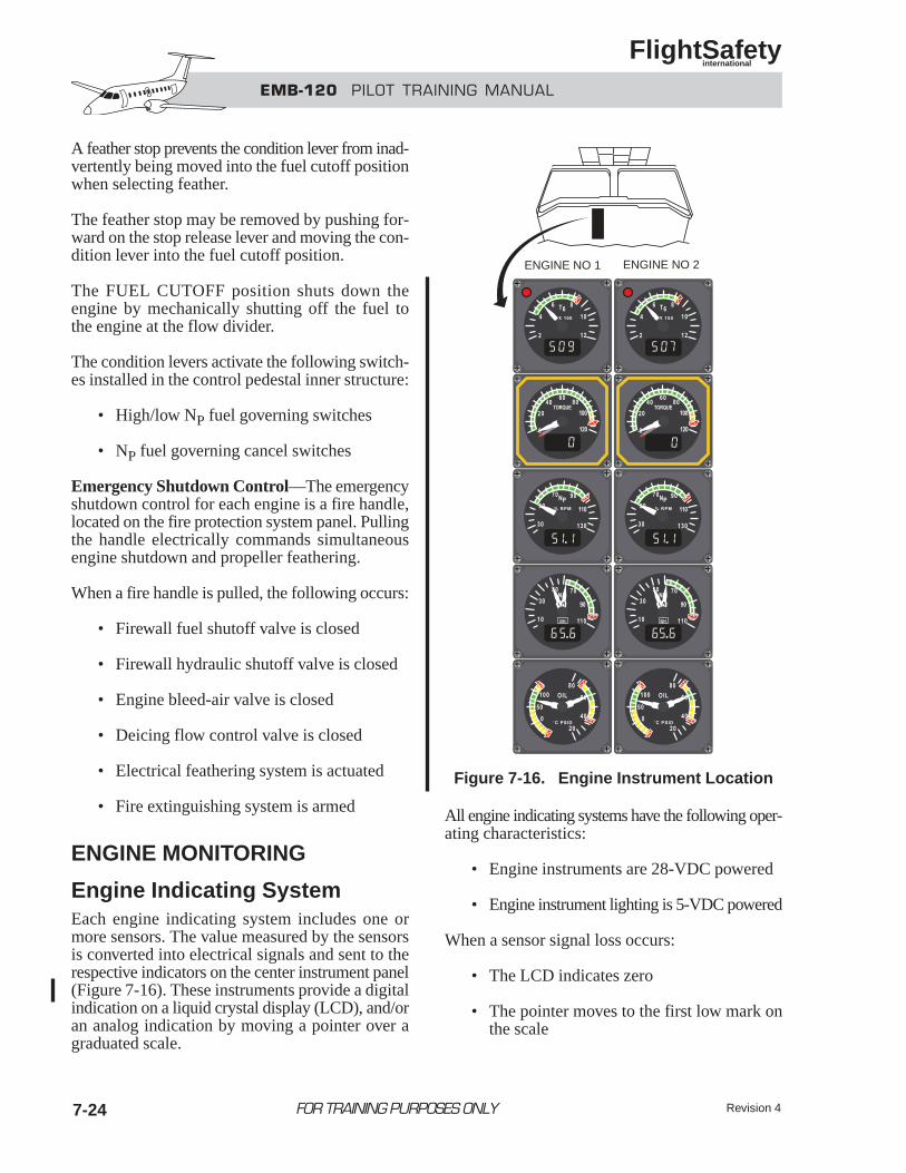
EMB-120 PILOT TRAINING MANUAL
FlightSafety international
Revision 47-24
A feather stop prevents the condition lever from inad-vertently being moved into the fuel cutoff positionwhen selecting feather.
The feather stop may be removed by pushing for-ward on the stop release lever and moving the con-dition lever into the fuel cutoff position.
The FUEL CUTOFF position shuts down theengine by mechanically shutting off the fuel tothe engine at the flow divider.
The condition levers activate the following switch-es installed in the control pedestal inner structure:
• High/low NP fuel governing switches
• NP fuel governing cancel switches
Emergency Shutdown Control—The emergencyshutdown control for each engine is a fire handle,located on the fire protection system panel. Pullingthe handle electrically commands simultaneousengine shutdown and propeller feathering.
When a fire handle is pulled, the following occurs:
• Firewall fuel shutoff valve is closed
• Firewall hydraulic shutoff valve is closed
• Engine bleed-air valve is closed
• Deicing flow control valve is closed
• Electrical feathering system is actuated
• Fire extinguishing system is armed
ENGINE MONITORING
Engine Indicating SystemEach engine indicating system includes one ormore sensors. The value measured by the sensorsis converted into electrical signals and sent to therespective indicators on the center instrument panel(Figure 7-16). These instruments provide a digitalindication on a liquid crystal display (LCD), and/oran analog indication by moving a pointer over a graduated scale.
All engine indicating systems have the following oper-ating characteristics:
• Engine instruments are 28-VDC powered
• Engine instrument lighting is 5-VDC powered
When a sensor signal loss occurs:
• The LCD indicates zero
• The pointer moves to the first low mark onthe scale
FOR TRAINING PURPOSES ONLY
ENGINE NO 1 ENGINE NO 2
Figure 7-16. Engine Instrument Location
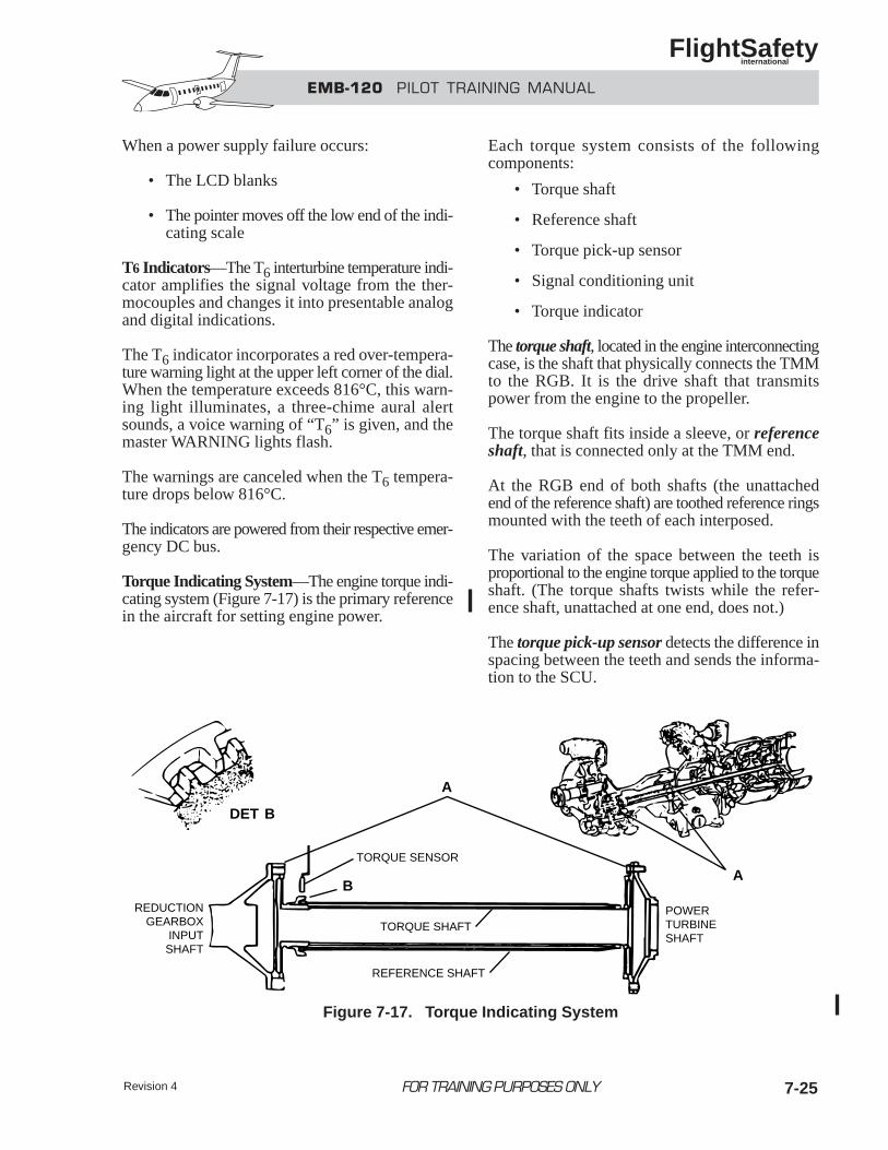
EMB-120 PILOT TRAINING MANUAL
FlightSafety international
Revision 4 7-25
When a power supply failure occurs:
• The LCD blanks
• The pointer moves off the low end of the indi-cating scale
T6 Indicators—The T6 interturbine temperature indi-cator amplifies the signal voltage from the ther-mocouples and changes it into presentable analogand digital indications.
The T6 indicator incorporates a red over-tempera-ture warning light at the upper left corner of the dial.When the temperature exceeds 816°C, this warn-ing light illuminates, a three-chime aural alertsounds, a voice warning of “T6” is given, and themaster WARNING lights flash.
The warnings are canceled when the T6 tempera-ture drops below 816°C.
The indicators are powered from their respective emer-gency DC bus.
Torque Indicating System—The engine torque indi-cating system (Figure 7-17) is the primary referencein the aircraft for setting engine power.
Each torque system consists of the followingcomponents:
• Torque shaft
• Reference shaft
• Torque pick-up sensor
• Signal conditioning unit
• Torque indicator
The torque shaft, located in the engine interconnectingcase, is the shaft that physically connects the TMMto the RGB. It is the drive shaft that transmitspower from the engine to the propeller.
The torque shaft fits inside a sleeve, or referenceshaft, that is connected only at the TMM end.
At the RGB end of both shafts (the unattachedend of the reference shaft) are toothed reference ringsmounted with the teeth of each interposed.
The variation of the space between the teeth isproportional to the engine torque applied to the torqueshaft. (The torque shafts twists while the refer-ence shaft, unattached at one end, does not.)
The torque pick-up sensor detects the difference inspacing between the teeth and sends the informa-tion to the SCU.
FOR TRAINING PURPOSES ONLY
TORQUE SENSOR
TORQUE SHAFT
REFERENCE SHAFT
B
A
A
REDUCTIONGEARBOX
INPUTSHAFT
POWERTURBINESHAFT
BDET
Figure 7-17. Torque Indicating System
EMB-120 PILOT TRAINING MANUAL
FlightSafety international
The signal conditioning unit (SCU) generates a cal-ibrated torque signal, which drives the analogpointer and LCD of the torque indicator on the maininstrument panel. It also supplies information to theautofeather system for arming and activation.
The torque indicator of each engine is powered bythe respective emergency DC bus.
Speed Indicating System—The following speedsensors transmit proportional train of pulses to thedigital and/or analog indicator. In addition, they alsosend signals to the EEC which uses them for enginefuel control scheduling.
The propeller speed (NP) sensor is located onthe RGB.
The high-pressure spool speed (NH) sensor,is located on the upper portion of the TMM acces-sories gearbox.
The low-pressure spool speed (NL) sensor is locat-ed on the left side of the engine near the compres-sor case.
NOTEThe LCD display on the NH /NL indicatordisplays NH.
The indicators are powered from the respectiveDC buses.
Oil Indicating System—The engine oil indicatingsystem is discussed in the Engine Oil System sec-tion of this chapter.
A summary of engine indicators and their param-eters for the PW 118 and PW 118A engines ispresented in Figure 7-18.
Figure 7-19 illustrates the powerplant control pan-els and indicates the functions of each.
FOR TRAINING PURPOSES ONLY Revision 47-26
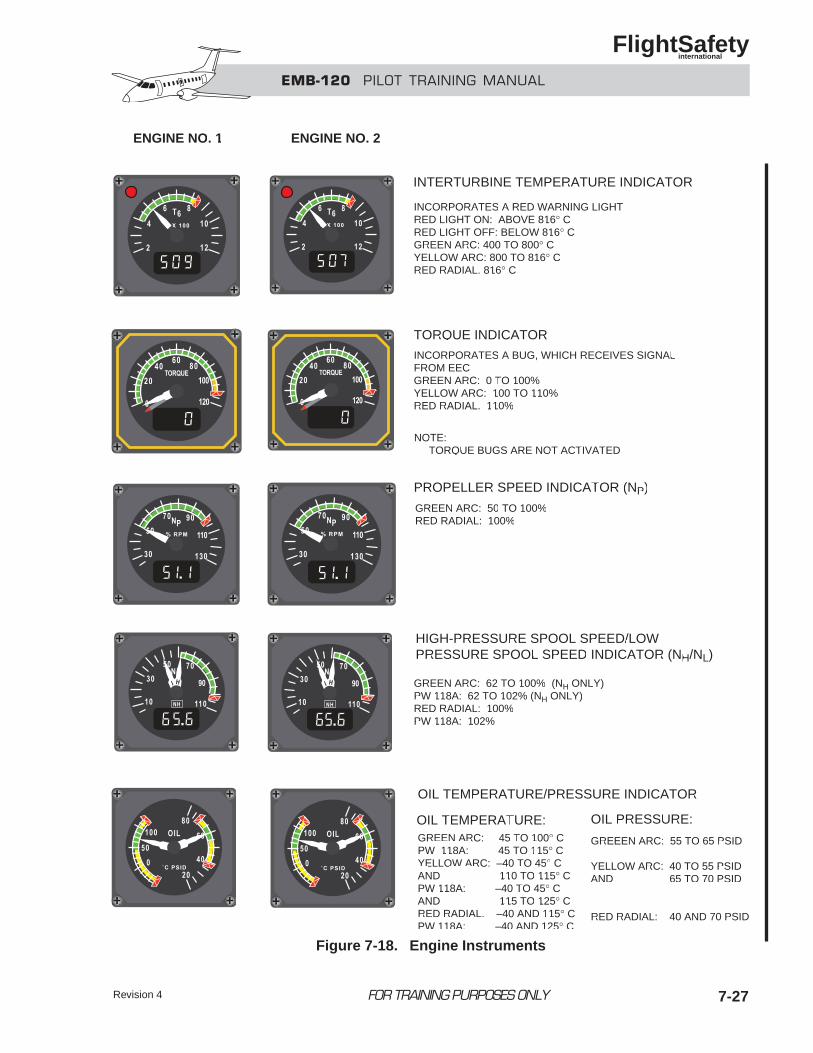
EMB-120 PILOT TRAINING MANUAL
FlightSafety international
FOR TRAINING PURPOSES ONLY 7-27Revision 4
ENGINE NO. 1 ENGINE NO. 2
INTERTURBINE TEMPERATURE INDICATOR
INCORPORATES A RED WARNING LIGHTRED LIGHT ON: ABOVE 816° CRED LIGHT OFF: BELOW 816° CGREEN ARC: 400 TO 800° CYELLOW ARC: 800 TO 816° CRED RADIAL: 816° C
TORQUE INDICATOR
PROPELLER SPEED INDICATOR (NP)
HIGH-PRESSURE SPOOL SPEED/LOWPRESSURE SPOOL SPEED INDICATOR (NH/NL)
OIL TEMPERATURE/PRESSURE INDICATOR
INCORPORATES A BUG, WHICH RECEIVES SIGNAL FROM EECGREEN ARC: 0 TO 100%YELLOW ARC: 100 TO 110%RED RADIAL: 110%
GREEN ARC: 50 TO 100%RED RADIAL: 100%
GREEN ARC: 62 TO 100% (NH ONLY)PW 118A: 62 TO 102% (NH ONLY)RED RADIAL: 100%PW 118A: 102%
NOTE: TORQUE BUGS ARE NOT ACTIVATED
OIL TEMPERATURE:GREEN ARC: 45 TO 100° CPW 118A: 45 TO 115° CYELLOW ARC: –40 TO 45° CAND 110 TO 115° CPW 118A: –40 TO 45° CAND 115 TO 125° CRED RADIAL: –40 AND 115° CPW 118A: –40 AND 125° C
GREEEN ARC: 55 TO 65 PSID
YELLOW ARC: 40 TO 55 PSIDAND 65 TO 70 PSID
RED RADIAL: 40 AND 70 PSID
OIL PRESSURE:
Figure 7-18. Engine Instruments
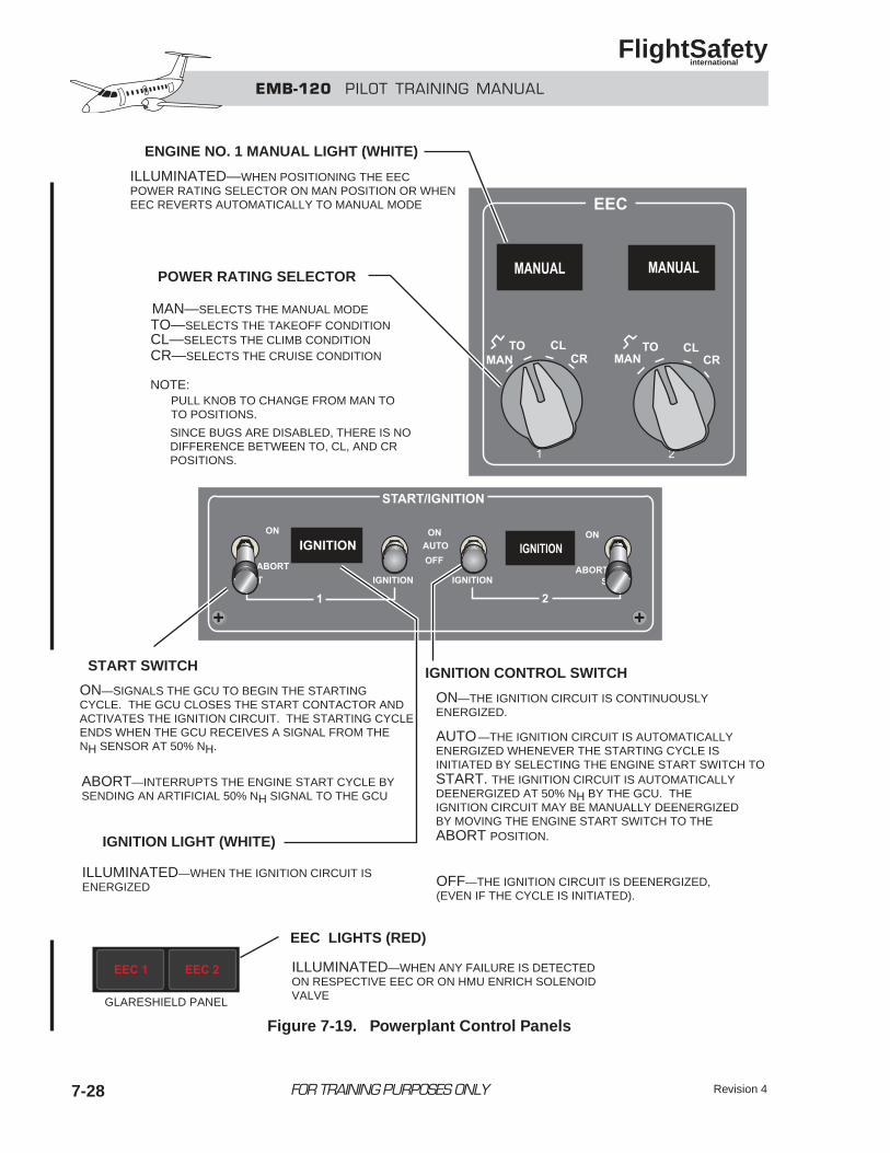
EMB-120 PILOT TRAINING MANUAL
FlightSafety international
Revision 47-28 FOR TRAINING PURPOSES ONLY
ENGINE NO. 1 MANUAL LIGHT (WHITE)
POWER RATING SELECTOR
START SWITCH
IGNITION LIGHT (WHITE)
EEC LIGHTS (RED)
IGNITION CONTROL SWITCH
ILLUMINATED—WHEN POSITIONING THE EECPOWER RATING SELECTOR ON MAN POSITION OR WHENEEC REVERTS AUTOMATICALLY TO MANUAL MODE
MAN—SELECTS THE MANUAL MODETO—SELECTS THE TAKEOFF CONDITIONCL—SELECTS THE CLIMB CONDITIONCR—SELECTS THE CRUISE CONDITION
NOTE:
ILLUMINATED—WHEN THE IGNITION CIRCUIT ISENERGIZED
ILLUMINATED—WHEN ANY FAILURE IS DETECTEDON RESPECTIVE EEC OR ON HMU ENRICH SOLENOIDVALVE
ON—THE IGNITION CIRCUIT IS CONTINUOUSLYENERGIZED.
START. THE IGNITION CIRCUIT IS AUTOMATICALLYDEENERGIZED AT 50% NH BY THE GCU. THEIGNITION CIRCUIT MAY BE MANUALLY DEENERGIZEDBY MOVING THE ENGINE START SWITCH TO THE ABORT POSITION.
OFF—THE IGNITION CIRCUIT IS DEENERGIZED,(EVEN IF THE CYCLE IS INITIATED).
PULL KNOB TO CHANGE FROM MAN TOTO POSITIONS.
SINCE BUGS ARE DISABLED, THERE IS NODIFFERENCE BETWEEN TO, CL, AND CRPOSITIONS.
ON—SIGNALS THE GCU TO BEGIN THE STARTINGCYCLE. THE GCU CLOSES THE START CONTACTOR ANDACTIVATES THE IGNITION CIRCUIT. THE STARTING CYCLEENDS WHEN THE GCU RECEIVES A SIGNAL FROM THENH SENSOR AT 50% NH.
ABORT—INTERRUPTS THE ENGINE START CYCLE BYSENDING AN ARTIFICIAL 50% NH SIGNAL TO THE GCU
TECH C
—THE IGNITION CIRCUIT IS AUTOMATICALLYENERGIZED WHENEVER THE STARTING CYCLE ISINITIATED BY SELECTING THE ENGINE START SWITCH TO
AUTO
GLARESHIELD PANEL
Figure 7-19. Powerplant Control Panels
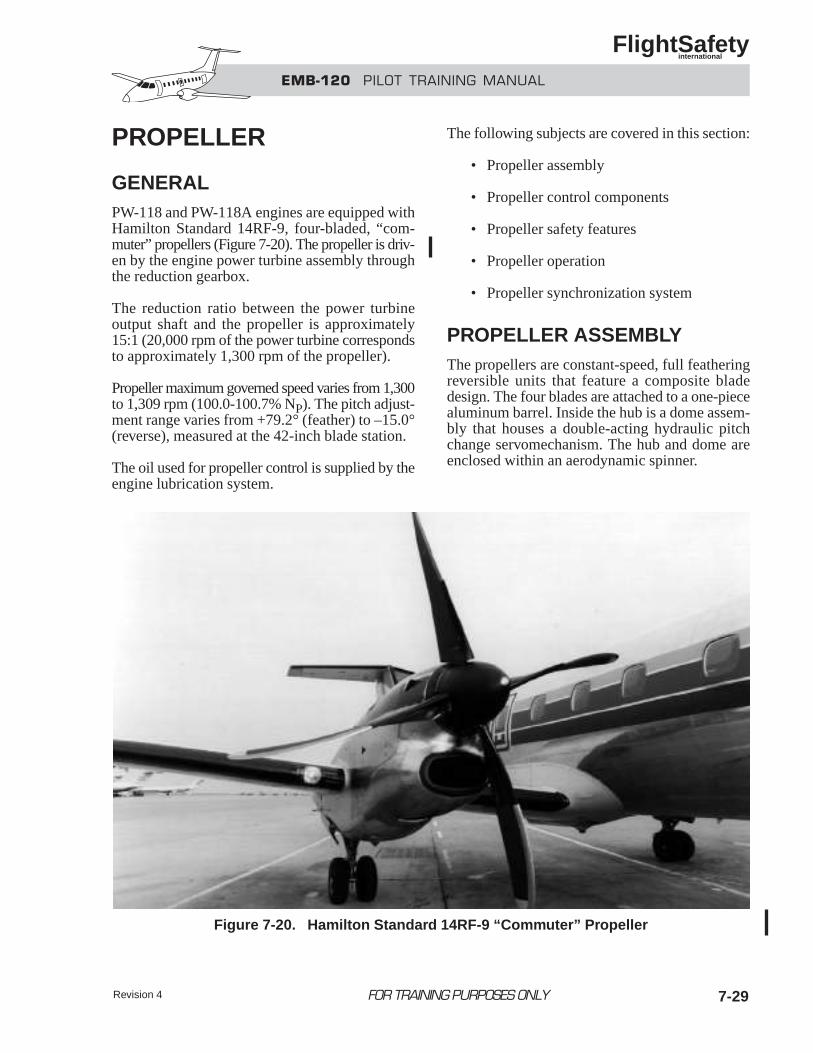
EMB-120 PILOT TRAINING MANUAL
FlightSafety international
7-29
PROPELLER
GENERALPW-118 and PW-118A engines are equipped withHamilton Standard 14RF-9, four-bladed, “com-muter” propellers (Figure 7-20). The propeller is driv-en by the engine power turbine assembly throughthe reduction gearbox.
The reduction ratio between the power turbineoutput shaft and the propeller is approximately15:1 (20,000 rpm of the power turbine correspondsto approximately 1,300 rpm of the propeller).
Propeller maximum governed speed varies from 1,300to 1,309 rpm (100.0-100.7% NP). The pitch adjust-ment range varies from +79.2° (feather) to –15.0°(reverse), measured at the 42-inch blade station.
The oil used for propeller control is supplied by theengine lubrication system.
The following subjects are covered in this section:
• Propeller assembly
• Propeller control components
• Propeller safety features
• Propeller operation
• Propeller synchronization system
PROPELLER ASSEMBLYThe propellers are constant-speed, full featheringreversible units that feature a composite bladedesign. The four blades are attached to a one-piecealuminum barrel. Inside the hub is a dome assem-bly that houses a double-acting hydraulic pitchchange servomechanism. The hub and dome areenclosed within an aerodynamic spinner.
FOR TRAINING PURPOSES ONLY
Figure 7-20. Hamilton Standard 14RF-9 “Commuter” Propeller
Revision 4
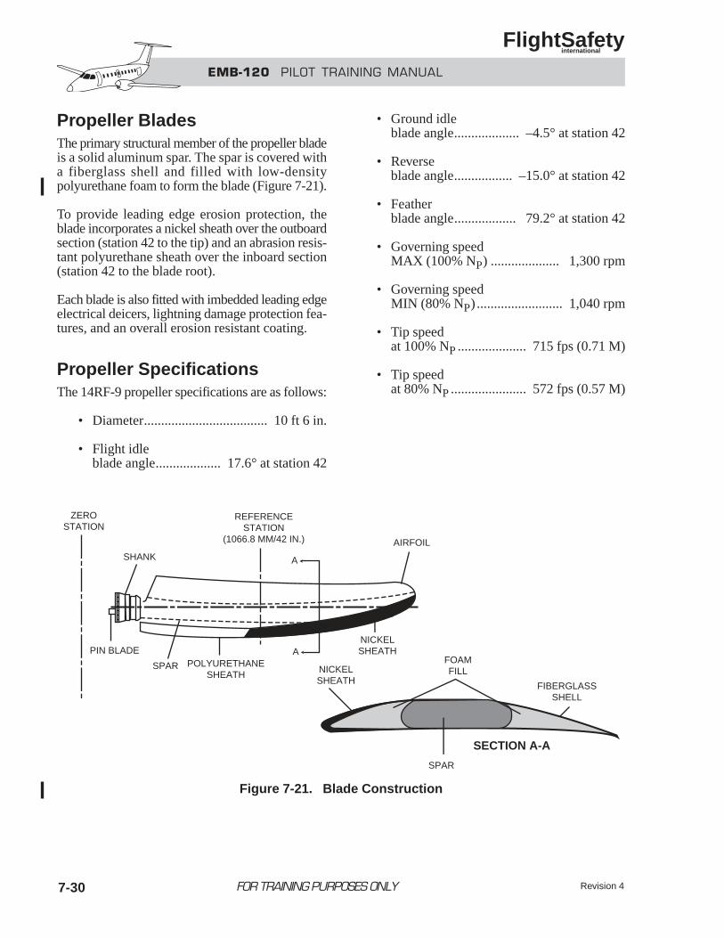
EMB-120 PILOT TRAINING MANUAL
FlightSafety international
Revision 47-30
Propeller BladesThe primary structural member of the propeller bladeis a solid aluminum spar. The spar is covered witha fiberglass shell and filled with low-densitypolyurethane foam to form the blade (Figure 7-21).
To provide leading edge erosion protection, theblade incorporates a nickel sheath over the outboardsection (station 42 to the tip) and an abrasion resis-tant polyurethane sheath over the inboard section(station 42 to the blade root).
Each blade is also fitted with imbedded leading edgeelectrical deicers, lightning damage protection fea-tures, and an overall erosion resistant coating.
Propeller SpecificationsThe 14RF-9 propeller specifications are as follows:
• Diameter.................................... 10 ft 6 in.
• Flight idleblade angle................... 17.6° at station 42
• Ground idleblade angle................... –4.5° at station 42
• Reverseblade angle................. –15.0° at station 42
• Featherblade angle.................. 79.2° at station 42
• Governing speedMAX (100% NP) .................... 1,300 rpm
• Governing speedMIN (80% NP) ......................... 1,040 rpm
• Tip speedat 100% NP .................... 715 fps (0.71 M)
• Tip speedat 80% NP ...................... 572 fps (0.57 M)
FOR TRAINING PURPOSES ONLY
ZEROSTATION
SHANK
REFERENCESTATION
(1066.8 MM/42 IN.) AIRFOIL
NICKELSHEATH
POLYURETHANESHEATH
SPAR
PIN BLADE
SPAR
FIBERGLASSSHELL
FOAMFILLNICKEL
SHEATH
A
A
SECTION A-A
Figure 7-21. Blade Construction
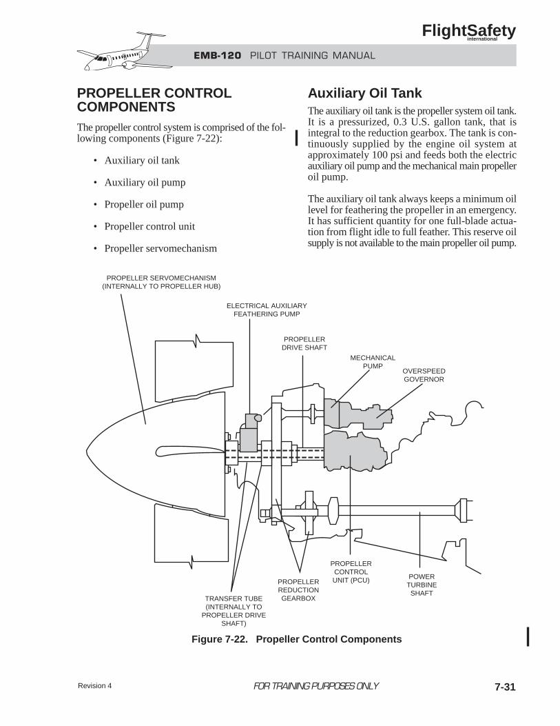
EMB-120 PILOT TRAINING MANUAL
FlightSafety international
Revision 4 7-31
PROPELLER CONTROL COMPONENTSThe propeller control system is comprised of the fol-lowing components (Figure 7-22):
• Auxiliary oil tank
• Auxiliary oil pump
• Propeller oil pump
• Propeller control unit
• Propeller servomechanism
Auxiliary Oil TankThe auxiliary oil tank is the propeller system oil tank.It is a pressurized, 0.3 U.S. gallon tank, that isintegral to the reduction gearbox. The tank is con-tinuously supplied by the engine oil system atapproximately 100 psi and feeds both the electricauxiliary oil pump and the mechanical main propelleroil pump.
The auxiliary oil tank always keeps a minimum oillevel for feathering the propeller in an emergency.It has sufficient quantity for one full-blade actua-tion from flight idle to full feather. This reserve oilsupply is not available to the main propeller oil pump.
FOR TRAINING PURPOSES ONLY
PROPELLER SERVOMECHANISM(INTERNALLY TO PROPELLER HUB)
ELECTRICAL AUXILIARYFEATHERING PUMP
PROPELLERDRIVE SHAFT
MECHANICALPUMP
OVERSPEEDGOVERNOR
TRANSFER TUBE(INTERNALLY TO
PROPELLER DRIVESHAFT)
PROPELLERREDUCTIONGEARBOX
PROPELLERCONTROLUNIT (PCU) POWER
TURBINESHAFT
Figure 7-22. Propeller Control Components
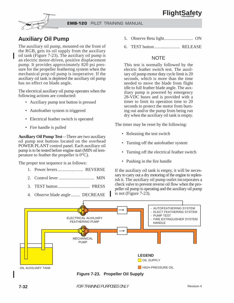
EMB-120 PILOT TRAINING MANUAL
FlightSafety international
FOR TRAINING PURPOSES ONLY
Auxiliary Oil PumpThe auxiliary oil pump, mounted on the front ofthe RGB, gets its oil supply from the auxiliaryoil tank (Figure 7-23). The auxiliary oil pump isan electric motor-driven, positive displacementpump. It provides approximately 820 psi pres-sure for the propeller feathering system when themechanical prop oil pump is inoperative. If theauxiliary oil tank is depleted the auxiliary oil pumphas no effect on blade angle.
The electrical auxiliary oil pump operates when thefollowing actions are conducted:
• Auxiliary pump test button is pressed
• Autofeather system is triggered
• Electrical feather switch is operated
• Fire handle is pulled
Auxiliary Oil Pump Test—There are two auxiliaryoil pump test buttons located on the overheadPOWER PLANT control panel. Each auxiliary oilpump is to be tested before engine start (MIN oil tem-perature to feather the propeller is 0°C).
The proper test sequence is as follows:
1. Power levers ....................... REVERSE
2. Control lever ................................ MIN
3. TEST button............................. PRESS
4. Observe blade angle ........ DECREASE
5. Observe Beta light.......................... ON
6. TEST button ....................... RELEASE
NOTEThis test is normally followed by theelectric feather switch test. The auxil-iary oil pump motor duty cycle limit is 20seconds, which is more than the timeneeded to move the blade from flightidle to full feather blade angle. The aux-iliary pump is powered by emergency28-VDC buses and is provided with atimer to limit its operation time to 20seconds to protect the motor from burn-ing out and/or the pump from being rundry when the auxiliary oil tank is empty.
The timer may be reset by the following:
• Releasing the test switch
• Turning off the autofeather system
• Turning off the electrical feather switch
• Pushing in the fire handle
If the auxiliary oil tank is empty, it will be neces-sary to carry out a dry motoring of the engine to replen-ish it. The auxiliary oil pump outlet incorporates acheck valve to prevent reverse oil flow when the pro-peller oil pump is operating and the auxiliary oil pumpis not (Figure 7-23).
Revision 47-32
- AUTOFEATHERING SYSTEM- ELECT FEATHERING SYSTEM- PUMP TEST- FIRE EXTINGUISHER SYSTEM HANDLE
ELECTRICAL AUXILIARYFEATHERING PUMP
MECHANICALPUMP
OIL SUPPLY
HIGH-PRESSURE OIL
LEGEND
OIL AUXILIARY TANK
Figure 7-23. Propeller Oil Supply
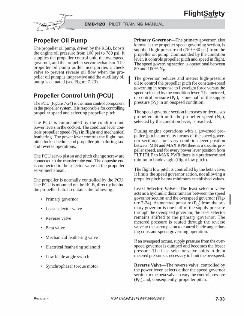
EMB-120 PILOT TRAINING MANUAL
FlightSafety international
7-33FOR TRAINING PURPOSES ONLYRevision 4
Propeller Oil PumpThe propeller oil pump, driven by the RGB, booststhe engine oil pressure from 100 psi to 780 psi. Itsupplies the propeller control unit, the overspeedgovernor, and the propeller servomechanism. Thepropeller oil pump outlet incorporates a checkvalve to prevent reverse oil flow when the pro-peller oil pump is inoperative and the auxiliary oilpump is actuated (see Figure 7-23).
Propeller Control Unit (PCU)The PCU (Figure 7-24) is the main control componentin the propeller system. It is responsible for controllingpropeller speed and selecting propeller pitch.
The PCU is commanded by the condition andpower levers in the cockpit. The condition lever con-trols propeller speed (NP) in flight and mechanicalfeathering. The power lever controls the flight low-pitch lock schedule and propeller pitch during taxiand reverse operations.
The PCU servo piston and pitch change screw areconnected to the transfer tube end. The opposite endis connected to the selector valve in the propellerservomechanism.
The propeller is normally controlled by the PCU.The PCU is mounted on the RGB, directly behindthe propeller hub. It contains the following:
• Primary governor
• Least selector valve
• Reverse valve
• Beta valve
• Mechanical feathering valve
• Electrical feathering solenoid
• Low blade angle switch
• Synchrophaser torque motor
Primary Governor—The primary governor, alsoknown as the propeller speed governing section, issupplied high-pressure oil (780 ±30 psi) from thepropeller oil pump. Commanded by the conditionlever, it controls propeller pitch and speed in flight.The speed governing section is operational between80 and 100% NP.
The governor reduces and meters high-pressureoil to control the propeller pitch for constant-speedgoverning in response to flyweight force versus thespeed selected by the condition lever. The metered,or control pressure (PC), is one half of the supplypressure (PS) in an onspeed condition.
The speed governor section increases or decreasespropeller pitch until the propeller speed (NP),selected by the condition lever, is reached.
During engine operations with a governed pro-peller (pitch control by means of the speed gover-nor section)—for every condition lever positionbetween MIN and MAX RPM there is a specific pro-peller speed, and for every power lever position fromFLT IDLE to MAX PWR there is a predeterminedminimum blade angle (flight low pitch).
The flight low pitch is controlled by the beta valve.It limits the speed governor action, not allowing apropeller pitch below minimum established values.
Least Selector Valve—The least selector valveacts as a hydraulic discriminator between the speedgovernor section and the overspeed governor (Fig-ure 7-24). As metered pressure (PC) from the pri-mary governor is one half of the supply pressurethrough the overspeed governor, the least selectorremains shifted to the primary governor. Themetered pressure is routed through the reversevalve to the servo piston to control blade angle dur-ing constant-speed governing operation.
If an overspeed occurs, supply pressure from the over-speed governor is dumped and becomes the lesserpressure. The least selector valve shifts to drainmetered pressure as necessary to limit the overspeed.
Reverse Valve—The reverse valve, controlled bythe power lever, selects either the speed governorsection or the beta valve to vary the control pressure(PC) and, consequently, propeller pitch.
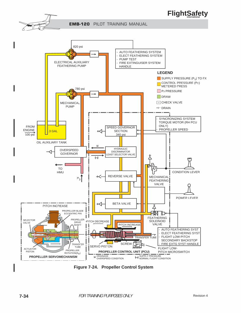
EMB-120 PILOT TRAINING MANUAL
FlightSafety international
Revision 47-34 FOR TRAINING PURPOSES ONLY
PITCH INCREASE
PROPELLER SERVOMECHANISM
TRANSFERTUBE
PROPELLERDRIVESHAFT
- AUTO FEATHERING SYSTEM- ELECT FEATHERING SYSTEM- PUMP TEST- FIRE EXTINGUISER SYSTEM HANDLE
SPEED GOVERNORSECTION
340 psi
HYDRAULICDISCRIMINATOR
LEAST SELECTOR VALVE
REVERSE VALVE
OVERSPEEDGOVERNOR
ELECTRICAL AUXILIARYFEATHERING PUMP
MECHANICALPUMP
OIL AUXILIARY TANK
TOHMU
- SYNCRONIZING SYSTEM TORQUE MOTOR (RH PCU ONLY)- PROPELLER SPEED
- AUTO FEATHERING SYST- ELECT FEATHERING SYST- FLIGHT LOW-PITCH SECONDARY BACKSTOP- FIRE EXTG SYST HANDLE
BETA VALVE
POWER LEVER
CONDITION LEVER
MECHANICALFEATHERING
VALVE
FEATHERINGSOLEINOID
VALVEPITCH INCREASEPITCH DECREASE
SCREWSERVO PISTON
PROPELLER CONTROL UNIT (PCU)FLIGHT LOW-PITCH MICROSWITCH
TRANSFER TUBE
DRAINAGEOVERSPEED CONDITION
SUPPLY PRESSURENORMAL FLIGHT CONDITION
( )*
( )*
**( )
**( )
SUPPLY PRESSURE (PS) TO FX
CONTROL PRESSURE (PC)METERED PRESS
P3 PRESSURE
DRAW
CHECK VALVE
DRAIN
LEGEND
SELECTORVALVE
ACTUATORPISTON
PROPELLER BLADEECCENTRIC PIN
PROPELLERROTATION(NP)
820 psi
780 psi
.3 GAL
FROMENGINE
100 psi
P3
Figure 7-24. Propeller Control System
EMB-120 PILOT TRAINING MANUAL
FlightSafety international
Revision 4 7-35FOR TRAINING PURPOSES ONLY
For power lever positions from FLT IDLE to MAXPWR, (typical in-flight positions), the reverse valveuses the speed governor section to control propellerpitch, down to the flight low pitch backstop limit.
For power lever positions from FLT IDLE down tomaximum reverse (typical on ground positions), thereverse valve hydraulically blocks the speed gov-ernor section and propeller pitch control is by theBeta valve.
Never select the power levers below FLTIDLE in flight.
In flight, the power lever operating range must belimited to positions equal to or above FLT IDLE.It ensures governed blade angles (speed governorsection controlling the propeller pitch) that are farabove those commanded by the Beta valve.
The actuation of the reverse valve in flight (powerlever below FLT IDLE) disables both the speed gov-ernor section and the overspeed governor, and con-trols the propeller pitch angles using the Beta valveschedule (minimum blade angle schedule). TheBeta schedule angles are much lower, towards flatpitch, than the angles scheduled by the speed gov-ernor section. This reduced blade angle in flight caus-es the propeller to extract energy from the airstream,driving the power turbine shaft to very high over-speed. Serious damage to the engine and excessivepropeller drag may result.
Beta Valve—During ground operation, as thepower lever is moved aft of flight idle into theground range, the Beta cam schedules the Betavalve to command blade angle.
The Beta valve is commanded by the power lever.In flight it controls the primary low pitch backstop,on the ground it controls propeller pitch for taxi andreverse operations.
On the ground, with the propeller operating in the Betamode (pitch control by means of the Beta valve)—for every power lever position from maximum
reverse to just below FLT IDLE there is a correspondingpredetermined blade angle.
During taxi and reverse operations, propeller speed(NP) is controlled by the EEC:
• With the condition lever at MAX RPM andthe power lever between FLT IDLE and 10°PLA (just below GND IDLE), the EECensures a minimum speed of 65% NP.
• With the condition lever between MAX andMIN RPM, the EEC assures a minimumspeed of 50% NP for every power leverposition
• With EEC OFF, the propeller speed dependsupon pressure altitude and air density.
In flight, and with the power lever between FLT IDLEand MAX PWR, the Beta valve acts as a propellerpitch backstop. This ensures that blade angles willnot be lower than the pre-established minimums.
At FLT IDLE, the low pitch is 17.6° (at blade sta-tion 42). This low-pitch value increases as thepower lever is moved above FLT IDLE.
With the power lever below FLT IDLE, the propellerblades are positioned below the flight low pitch. Thiscondition is indicated by the illumination of the Betalight on the glareshield. The Beta light illuminatesanytime blade angle is 12.6° or less, (5° below theflight low pitch corresponding to FLT IDLE posi-tion). The Beta lights are normally illuminatedduring taxi and reverse operations.
NOTEBeta light illumination in flight is abnor-mal. It indicates either Beta valve failurein limiting the flight low pitch, or a fail-ure in the Beta indication circuit.
Mechanical Feathering Valve—The mechanicalfeathering valve is actuated by the feather positionof the condition lever. It dumps metered pressure andallows supply pressure to feather the propeller.
WARNING
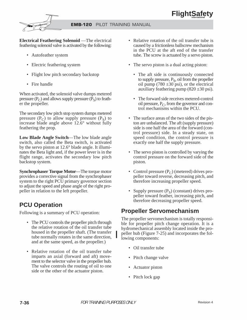
EMB-120 PILOT TRAINING MANUAL
FlightSafety international
Electrical Feathering Solenoid —The electricalfeathering solenoid valve is activated by the following:
• Autofeather system
• Electric feathering system
• Flight low pitch secondary backstop
• Fire handle
When activated, the solenoid valve dumps meteredpressure (PC) and allows supply pressure (PS) to feath-er the propeller.
The secondary low pitch stop system dumps meteredpressure (PC) to allow supply pressure (PS) toincrease blade angle above 12.6° without fullyfeathering the prop.
Low Blade Angle Switch—The low blade angleswitch, also called the Beta switch, is activatedby the servo piston at 12.6° blade angle. It illumi-nates the Beta light and, if the power lever is in theflight range, activates the secondary low pitchbackstop system.
Synchrophaser Torque Motor—The torque motorprovides a corrective signal from the synchrophasersystem to the right PCU primary governor sectionto adjust the speed and phase angle of the right pro-peller in relation to the left propeller.
PCU OperationFollowing is a summary of PCU operation:
• The PCU controls the propeller pitch throughthe relative rotation of the oil transfer tubehoused in the propeller shaft. (The transfertube normally rotates in the same direction,and at the same speed, as the propeller.)
• Relative rotation of the oil transfer tubeimparts an axial (forward and aft) move-ment to the selector valve in the propeller hub.The valve controls the routing of oil to oneside or the other of the actuator piston.
• Relative rotation of the oil transfer tube iscaused by a frictionless ballscrew mechanismin the PCU at the aft end of the transfertube. The screw is actuated by a servo piston.
• The servo piston is a dual acting piston:
• The aft side is continuously connectedto supply pressure, PS, oil from the propelleroil pump (780 ±30 psi), or the electricalauxiliary feathering pump (820 ±30 psi).
• The forward side receives metered-controloil pressure, PC, from the governor and con-trol mechanisms within the PCU.
• The surface areas of the two sides of the pis-ton are unbalanced. The aft (supply pressure)side is one half the area of the forward (con-trol pressure) side. In a steady state, onspeed condition, the control pressure isexactly one half the supply pressure.
• The servo piston is controlled by varying thecontrol pressure on the forward side of thepiston.
• Control pressure (PC) (metered) drives pro-peller toward reverse, decreasing pitch, andtherefore increasing propeller speed.
• Supply pressure (PS) (constant) drives pro-peller toward feather, increasing pitch, andtherefore decreasing propeller speed.
Propeller ServomechanismThe propeller servomechanism is totally responsi-ble for propeller pitch change operation. It is ahydromechanical assembly located inside the pro-peller hub (Figure 7-25) and incorporates the fol-lowing components:
• Oil transfer tube
• Pitch change valve
• Actuator piston
• Pitch lock gap
Revision 47-36 FOR TRAINING PURPOSES ONLY
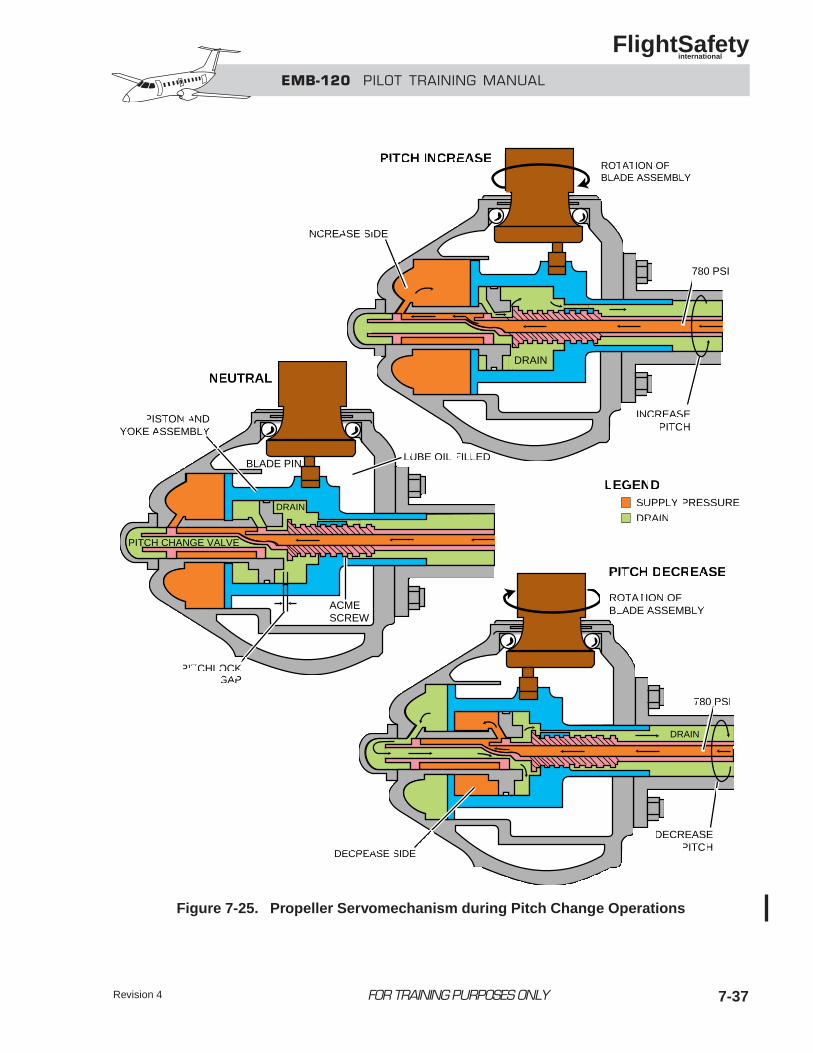
7-37FOR TRAINING PURPOSES ONLY
EMB-120 PILOT TRAINING MANUAL
FlightSafety international
Revision 4
PITCH INCREASE
NEUTRAL
LUBE OIL FILLED
ACMESCREW
BLADE PIN
INCREASE SIDE
DRAIN
INCREASEPITCH
780 PSI
ROTATION OFBLADE ASSEMBLY
PITCH DECREASE
ROTATION OFBLADE ASSEMBLY
PISTON ANDYOKE ASSEMBLY
PITCH CHANGE VALVE
SUPPLY PRESSURE
DRAIN
LEGEND
PITCHLOCKGAP
DRAIN
DRAIN
DECREASEPITCH
780 PSI
DECREASE SIDE
Figure 7-25. Propeller Servomechanism during Pitch Change Operations
EMB-120 PILOT TRAINING MANUAL
FlightSafety international
Revision 47-38
The oil transfer tube, pitch change valve, and actu-ator piston all rotate with the propeller.
Oil Transfer Tube—The oil transfer tube carriessupply pressure oil to the pitch change valve for oper-ating the actuator position. The tube is rotated (rel-ative to propeller rotation) by the frictionless ball-screw mechanism in the PCU (in response to foreand aft movement of the PCU servo piston). The tuberotation repositions the pitch change valve.
Pitch Change Valve—The pitch change valveassembly within the propeller servomechanismdirects supply pressure oil from the transfer tube tothe pitch increase or pitch decrease side of theactuator piston.
Part of the selector valve assembly is the reverse-threaded acme screw, which changes the transfer tube’srelative rotation into axial movement.
Actuator Piston—The actuator piston is a dual-act-ing assembly that repositions the propeller blade’soffcenter yoke assembly to change blade angle.
Supply oil is directed to the front side of the pistonto increase pitch and to the aft side of the piston todecrease pitch.
When either side of the piston is receiving supplyoil, the pitch change valve directs the oppositeside of the piston to drain.
Pitch Lock Gap—The pitch lock gap is a small(.030–inch) space between the acme screw portionof the selector valve assembly and the propeller hubassembly. Oil from either side of the actuator pis-ton passes through this gap to drain. Should the sup-ply of oil to the PCU fail, the aerodynamic forceson the propeller (which tend to drive it toward flatpitch) close the pitch lock gap. This shuts off the drainto both sides of the actuator piston, creating ahydraulic lock.
Propeller ServomechanismOperation
• Unbalanced PS/PC pressure on the PCUservo piston causes a rotation of the oiltransfer tube relative to the propeller shaft.
• In the servomechanism, the reverse thread-ed acme screw changes the tube’s relative rota-tion to fore or aft selector valve displacement.
• The valve is positioned such that one of theactuator piston chambers is connected tothe supply pressure, and the other is connectedto drain.
• Pressure to the forward side of the pistonincreases the blade angle toward feather.
• Pressure to the aft side of the pistondecreases the blade angle toward reverse.
• The actuator piston moves, repositioningboth the selector valve and the propellerblade eccentric pin. (The selector valve andactuator piston continue to move as long asthere is relative rotation of the transfer tube.)
• When the selected pitch is reached, the PCUservo piston returns to equilibrium, relativerotation of the transfer tube stops, the selec-tor valve returns to its balanced (actuator pis-ton chambers closed) position, and theactuator piston stops.
PROPELLER SAFETYFEATURESThe “commuter” propeller is equipped with the fol-lowing automatic and manual safety features:
• Overspeed governor
• Pitch lock
• Primary low pitch stop
• Secondary low pitch stop
• Mechanical feathering
• Electrical feathering
• Emergency feathering and shutdown
• Autofeather system
FOR TRAINING PURPOSES ONLY
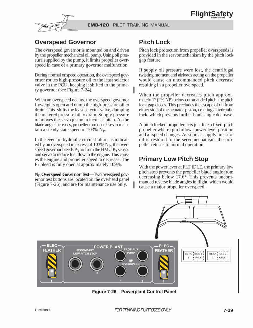
EMB-120 PILOT TRAINING MANUAL
FlightSafety international
Revision 4 7-39
Overspeed GovernorThe overspeed governor is mounted on and drivenby the propeller mechanical oil pump. Using oil pres-sure supplied by the pump, it limits propeller over-speed in case of a primary governor malfunction.
During normal onspeed operation, the overspeed gov-ernor routes high-pressure oil to the least selectorvalve in the PCU, keeping it shifted to the prima-ry governor (see Figure 7-24).
When an overspeed occurs, the overspeed governorflyweights open and dump the high-pressure oil todrain. This shifts the least selector valve, dumpingthe metered pressure oil to drain. Supply pressureoil moves the servo piston to increase pitch. As theblade angle increases, propeller rpm decreases to main-tain a steady state speed of 103% NP.
In the event of hydraulic circuit failure, as indicat-ed by an overspeed in excess of 103% NP, the over-speed governor bleeds P3 air from the HMU P3 sensorand servo to reduce fuel flow to the engine. This caus-es the engine and propeller speed to decrease. TheP3 bleed is fully open at approximately 109%.
NP Overspeed Governor Test—Two overspeed gov-ernor test buttons are located on the overhead panel(Figure 7-26), and are for maintenance use only.
Pitch LockPitch lock protection from propeller overspeeds isprovided in the servomechanism by the pitch lockgap feature.
If supply oil pressure were lost, the centrifugaltwisting moment and airloads acting on the propellerwould cause an uncommanded pitch decreaseresulting in a propeller overspeed.
When the propeller decreases pitch approxi-mately 1° (2% NP) below commanded pitch, the pitchlock gap closes. This precludes the escape of oil fromeither side of the actuator piston, creating a hydrauliclock, which prevents further blade angle decrease.
A pitch locked propeller acts just like a fixed-pitchpropeller where rpm follows power lever positionand airspeed changes. As soon as supply pressureoil is restored to the servomechanism, the pro-peller returns to normal operation.
Primary Low Pitch StopWith the power lever at FLT IDLE, the primary lowpitch stop prevents the propeller blade angle fromdecreasing below 17.6°. This prevents uncom-manded reverse blade angles in flight, which wouldcause a major propeller overspeed.
FOR TRAINING PURPOSES ONLY
BETA
1
BETA
2
IDLE 1
UNLK
IDLE 2
UNLK
Figure 7-26. Powerplant Control Panel
EMB-120 PILOT TRAINING MANUAL
FlightSafety international
Revision 47-40
When the power lever is moved below flight idle intothe ground (Beta) range, the primary low pitchstop is removed by the reverse valve to permitBeta range and reverse for ground operation.
Secondary Low Pitch StopWith the power lever at FLT IDLE or above, the sec-ondary low pitch stop prevents a propeller blade angleless than the flight low pitch in the event of a pri-mary low pitch stop failure. The system is auto-matically actuated when the propeller pitch decreasesbelow 12.6°.
The secondary low pitch stop system has twomicroswitches:
• Flight low pitch microswitch
• Secondary low pitch microswitch
The flight low pitch microswitch is actuated by thePCU piston. It closes whenever the propeller bladeangle is below 12.6° (5° below the flight low pitchcorresponding to FLT IDLE position).
The secondary low pitch microswitch is located with-in the control pedestal. It is closed whenever the powerlever is positioned at FLT IDLE or above (normalflight position).
When actuated, the secondary low pitch system caus-es the BETA light to illuminate and energizes thefeathering solenoid valve in the PCU.
When energized, the solenoid valve drains the con-trol pressure (PC) line, causing the propeller pitchto increase above 12.6°. The system is then deac-tivated by the opening of the low pitch microswitch,and the BETA light goes out.
If propeller pitch decreases again, the process is repeat-ed and propeller pitch will cycle around 12.6°.
NOTEAn in-flight failure of the low pitchmicroswitch (locking in the closed posi-tion) will suddenly feather the propeller.This condition is indicated by an NP
decrease and a torque increase. Reducethe power lever to FLT IDLE and openthe affected engine Beta circuit breaker,located on the circuit breaker panel (seechecklist).
Secondary Low Pitch Stop Test—Two secondarylow pitch stop test buttons are located on the over-head panel (see Figure 7-26).
BETA LightsTwo amber BETA lights on the left glareshieldpanel (see Figure 7-26) are illuminated wheneverthe propeller blade angle reaches 12.6°.
A flashing BETA light in flight indicates the primarylow pitch stop has failed and the secondary low pitchstop system is operating.
A BETA light during ground operations is nor-mal. (Primary low pitch stop is removed and sec-ondary is inhibited).
Mechanical FeatheringMechanical feathering is accomplished by positioningthe condition lever to feather. This opens themechanical feather valve, which dumps the servopiston metered pressure PC to drain. The remain-ing supply pressure shifts the servo piston, feath-ering the propeller.
With a propeller oil pump failure or reduction of oilsupply, mechanical feathering may not be possible.In this event, the electrical feathering system mustbe used to feather the propeller.
Electrical FeatheringThe propeller is electrically feathered by actuationof the feathering solenoid valve in the PCU, and theauxiliary electrical feathering pump.
The auxiliary electrical feathering pump suppliesoil pressure for propeller feathering independent ofthe engine lubricating circuit and mechanical oil pump.
FOR TRAINING PURPOSES ONLY
EMB-120 PILOT TRAINING MANUAL
FlightSafety international
Revision 4 7-41
When actuated, the pump operates for 20 secondsand turns off automatically. This is more thanenough time to fully feather the propeller, even fromreverse pitch.
The auxiliary electrical feathering pump test is con-ducted prior to engine start, as follows:
1. Power lever .............. MAX REVERSE
2. Condition lever ................... MIN RPM
3. PROP AUX PUMP button ....... PRESS
4. BETA light ..................................... ON
5. PROP AUXPUMP button...................... RELEASE
Electrical propeller feathering is controlled bythe following:
• Electrical feathering system which mayreceive inputs from either of the following:
• Automatic feathering system
• Emergency feathering system
Electrical Feathering System—The electricalfeathering system provides a means for propeller feath-ering in the following conditions:
• Engine oil pressure loss
• Engine inoperative
• Engine shutdown due to fire
The electrical feathering system is actuated by theguarded ELEC FEATHER switch on the overheadpanel (see Figure 7-26) or by input from either theautomatic or emergency feathering systems. The sys-tem is normally off, with the ELEC FEATHER switchguard lowered.
When the system is actuated the following occurs:
• PCU feathering solenoid valve is energized
• Electrical auxiliary feathering pump isenergized
• Automatic feathering system control circuitfor the opposite propeller is interrupted
Once turned off the electrical feathering system isavailable for immediate reuse, provided there is suf-ficient oil quantity in the oil auxiliary tank.
NOTEThe oil auxiliary tank may be replen-ished by dry motoring the engine.
Electric Feathering System Test
NOTEThe electric feather system test is conductedfollowing, and in conjunction with, the aux-iliary oil pump test. Therefore, the pro-peller blade angle is in the Beta range withthe engines not running.
The test is conducted as follows:
1. Power levers.............. GROUND IDLE
2. Electric feather switch........ FEATHER
3. BETA light................................... OUT
4. Observe propellerblade angle ......................... FEATHER
5. Electric feather switch ........ NORMAL
Automatic Feathering System— Electrically con-trolled automatic feathering is accomplished bythe autofeather system. The system improves air-craft performance by quickly reducing the asym-metrical drag of a windmilling propeller followinga power loss on takeoff or go around.
The autofeather system actuates the featheringsolenoid valve and the auxiliary electrical feather-ing pump through the electrical feathering system.
FOR TRAINING PURPOSES ONLY
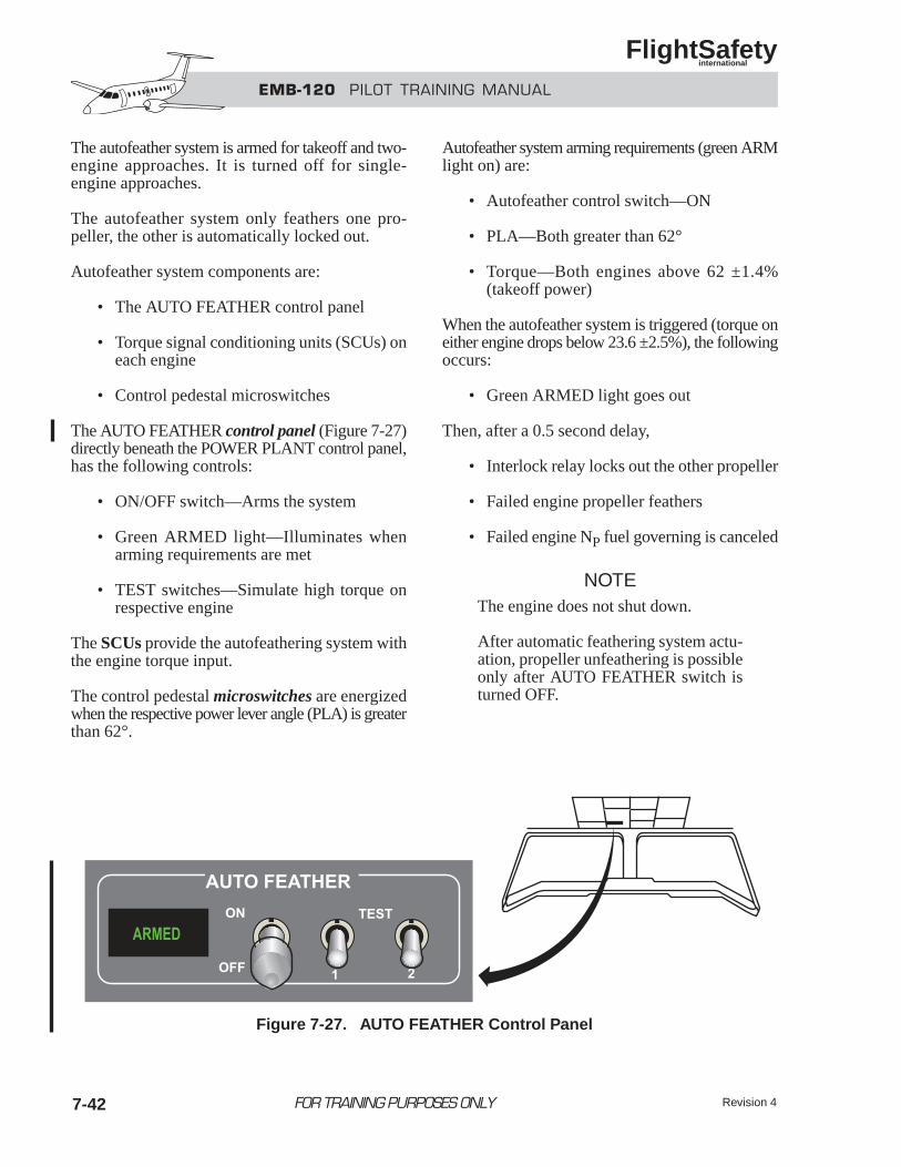
EMB-120 PILOT TRAINING MANUAL
FlightSafety international
Revision 47-42
The autofeather system is armed for takeoff and two-engine approaches. It is turned off for single-engine approaches.
The autofeather system only feathers one pro-peller, the other is automatically locked out.
Autofeather system components are:
• The AUTO FEATHER control panel
• Torque signal conditioning units (SCUs) oneach engine
• Control pedestal microswitches
The AUTO FEATHER control panel (Figure 7-27)directly beneath the POWER PLANT control panel,has the following controls:
• ON/OFF switch—Arms the system
• Green ARMED light—Illuminates whenarming requirements are met
• TEST switches—Simulate high torque onrespective engine
The SCUs provide the autofeathering system withthe engine torque input.
The control pedestal microswitches are energizedwhen the respective power lever angle (PLA) is greaterthan 62°.
Autofeather system arming requirements (green ARMlight on) are:
• Autofeather control switch—ON
• PLA—Both greater than 62°
• Torque—Both engines above 62 ±1.4%(takeoff power)
When the autofeather system is triggered (torque oneither engine drops below 23.6 ±2.5%), the followingoccurs:
• Green ARMED light goes out
Then, after a 0.5 second delay,
• Interlock relay locks out the other propeller
• Failed engine propeller feathers
• Failed engine NP fuel governing is canceled
NOTEThe engine does not shut down.
After automatic feathering system actu-ation, propeller unfeathering is possibleonly after AUTO FEATHER switch isturned OFF.
FOR TRAINING PURPOSES ONLY
Figure 7-27. AUTO FEATHER Control Panel
EMB-120 PILOT TRAINING MANUAL
FlightSafety international
Revision 4 7-43
When the power levers are advanced for takeoff and,after an eight-second delay, the autofeather systemis not armed, a three-chime aural alert sounds, anda “TAKEOFF AUTOFEATHER” voice messagewarning is given.
Autofeather Test Sequence—After engine start-ing and before each takeoff, the autofeather systemmust be tested for each propeller.
The satisfactory test sequence is as follows:
1. Autofeather control switch............. ON
2. Both power levers ..... GROUND IDLE
3. Both TEST switches................... TEST
4. Both torque indications ................ 75%
5. ARM light ...................................... ON
6. Left TEST switch ............... RELEASE
7. Left torqueindication ........... DROP BELOW 22%
8. ARM light .................................... OFF
9. Left NP.................. DROP TO 15–20%
10. Both TEST switches................... TEST
11. Both torque indications ................ 75%
12. ARM light ...................................... ON
13. Right TEST switch............. RELEASE
14. Right torque indication ........... DROP BELOW 22%
15. ARM light .................................... OFF
16. Right NP .................... Drop to 15–20%
17. Both TEST switches........... RELEASE
Emergency Feathering and Shutdown—Emer-gency feathering and shutdown are accomplishedby pulling the respective fire “T” handle.
Pulling the “T” handle results in the following:
• Electrically closes the firewall shutoff valvesto shut down and isolate the engine
• Actuates the feathering solenoid valve and theauxiliary electrical feathering pump, throughthe electrical feathering system, to feather thepropeller
PROPELLER OPERATION
Never select the power levers below FLTIDLE in flight.
Following is a review of actions that take place inthe PCU and in the hydraulic servomechanismwhen a pitch increase or decrease is commanded.
For pitch increase:
• The metered control pressure is reduced,allowing the supply pressure to move the PCUservo piston aft.
• The frictionless ball screw mechanism caus-es the transfer tube to rotate counterclockwise(relative to propeller rotation).
• The transfer tube rotation, via the pitchchange valve’s reverse-threaded acme screw,moves the valve forward.
• Supply pressure oil is routed to the increasepitch (forward) side of the piston, driving theblades to increase pitch via the blade shankoff-centered pin.
For pitch decrease:
• The metered control pressure is increased, over-riding the supply pressure and moving the PCUservo piston forward.
• The frictionless ballscrew mechanism caus-es the transfer tube to rotate clockwise (rel-ative to propeller rotation).
WARNING
FOR TRAINING PURPOSES ONLY
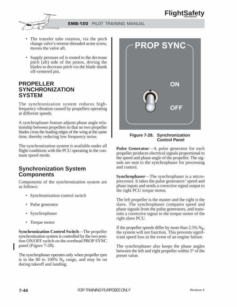
EMB-120 PILOT TRAINING MANUAL
FlightSafety international
Revision 47-44
• The transfer tube rotation, via the pitchchange valve’s reverse-threaded acme screw,moves the valve aft.
• Supply pressure oil is routed to the decreasepitch (aft) side of the piston, driving theblades to decrease pitch via the blade shankoff-centered pin.
PROPELLERSYNCHRONIZATIONSYSTEMThe synchronization system reduces high-frequency vibration caused by propellers operatingat different speeds.
A synchrophaser feature adjusts phase angle rela-tionship between propellers so that no two propellerblades cross the leading edges of the wing at the sametime, thereby reducing low frequency noise.
The synchronization system is available under allflight conditions with the PCU operating in the con-stant speed mode.
Synchronization SystemComponentsComponents of the synchronization system areas follows:
• Synchronization control switch
• Pulse generator
• Synchrophaser
• Torque motor
Synchronization Control Switch—The propellersynchronization system is controlled by the two posi-tion ON/OFF switch on the overhead PROP SYNCpanel (Figure 7-28).
The synchrophaser operates only when propeller rpmis in the 80 to 100% NP range, and may be onduring takeoff and landing.
Pulse Generator—A pulse generator for eachpropeller produces electrical signals proportional tothe speed and phase angle of the propeller. The sig-nals are sent to the synchrophaser for processing and control.
Synchrophaser—The synchrophaser is a micro-processor. It takes the pulse generators’ speed andphase inputs and sends a corrective signal output tothe right PCU torque motor.
The left propeller is the master and the right is theslave. The synchrophaser compares speed andphase signals from the pulse generators, and trans-mits a corrective signal to the torque motor of theright slave PCU.
If the propeller speeds differ by more than 2.5% NP,the system will not function. This prevents signif-icant speed loss in the event of an engine failure.
The synchrophaser also keeps the phase anglesbetween the left and right propeller within 5° of thepreset value.
FOR TRAINING PURPOSES ONLY
Figure 7-28. SynchronizationControl Panel
EMB-120 PILOT TRAINING MANUAL
FlightSafety international
FOR TRAINING PURPOSES ONLY
Torque Motor—The torque motor is a PCU component.
The right torque motor receives corrective signalsfrom the synchrophaser. It adjusts the speed of theright propeller, to match the left, by varying the pri-mary governor setting.
SynchronizationSystem OperationA difference between master and slave propeller NPmay be evidenced by an audible beat in propellernoise—the faster the beat, the greater the difference.
When audible beat or noise becomes noticeable, thebest operation of the synchronization system is asfollows:
1. Turn the synchrophaser OFF.
2. Set condition levers to the desired NP.
3. Match the NP as close as possible.
4. Turn the synchrophaser ON.
When speed sync is established, audible beatsshould subside.
After transients cease, the synchrophaser estab-lishes the desired phase relationship within approx-imately 18 seconds, and general noise level shouldbe reduced.
Turning the system off causes the slave propeller toreturn to its unbiased, mechanical rpm setting.
When the synchrophaser is not in use, a differencein governing rpm between propellers is normal. Con-dition lever positions may not match when NPindications are equal, normally due to hysteresis orrigging.
Figure 7-29 illustrates the propeller system controlsand indicators. Explanations of capabilities arealso included.
Revision 4 7-45
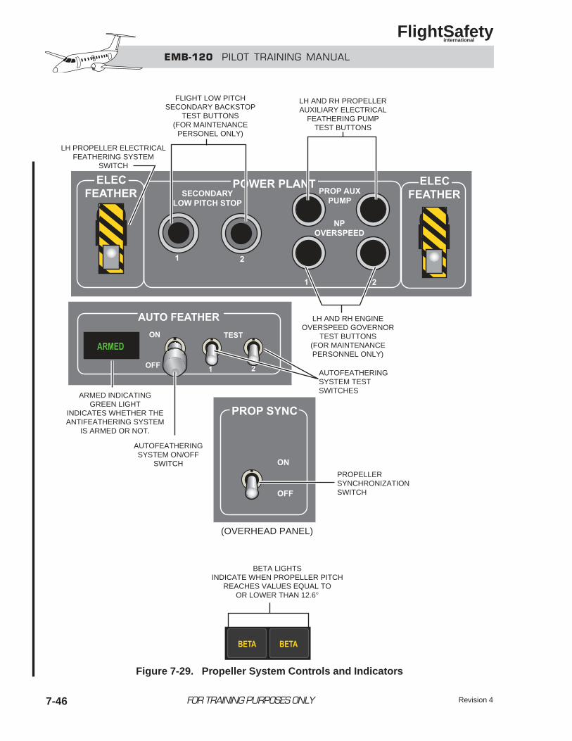
EMB-120 PILOT TRAINING MANUAL
FlightSafety international
FOR TRAINING PURPOSES ONLY Revision 47-46
LH PROPELLER ELECTRICALFEATHERING SYSTEM
SWITCH
FLIGHT LOW PITCHSECONDARY BACKSTOP
TEST BUTTONS(FOR MAINTENANCE
PERSONEL ONLY)
LH AND RH PROPELLERAUXILIARY ELECTRICAL
FEATHERING PUMPTEST BUTTONS
LH AND RH ENGINEOVERSPEED GOVERNOR
TEST BUTTONS(FOR MAINTENANCEPERSONNEL ONLY)
AUTOFEATHERINGSYSTEM TESTSWITCHES
PROPELLERSYNCHRONIZATIONSWITCH
AUTOFEATHERINGSYSTEM ON/OFF
SWITCH
ARMED INDICATINGGREEN LIGHT
INDICATES WHETHER THEANTIFEATHERING SYSTEM
IS ARMED OR NOT.
(OVERHEAD PANEL)
BETA LIGHTSINDICATE WHEN PROPELLER PITCH
REACHES VALUES EQUAL TOOR LOWER THAN 12.6°
Figure 7-29. Propeller System Controls and Indicators
EMB-120 PILOT TRAINING MANUAL
FlightSafety international
FOR TRAINING PURPOSES ONLYRevision 4 7-47
QUESTIONSEngine
1. The engines of the EMB 120 are:A. Garrett 1180 CB. Pratt-Whitney PW 118C. Air research 2131 EMBD. Pratt-Whitney PT6 EMB
2. The engine has how many compressors?A. 1B. 2C. 3D. 4
3. The engine has how many turbines?A. 1B. 2C. 3D. 4
4. The engine horsepower rating is:A. 1180B. 1800C. 1018D. 2131
5. Engine power control is accomplished byoperation of:A. Fuel control unit (FCU)B. Hydromechanical metering unit (HMU)C. Turbine limiting device (TLD)D. A combination of the electronic engine con-
trol (EEC) and the hydromechanical meter-ing unit (HMU)
6. The device that provides essential fuel controlfunctions in the absence of electrical power is:A. Turbine limiting device (TLD)B. Hydromechanical metering unit (HMU)C. Electronic engine control (EEC)D. Power surge control unit (PSCU)
7. The maximum torque allowed is:A. 100% for 15 minutesB. 110% for 5 minutesC. 120% for 5 minutesD. Maximum torque is limited by aircraft
weight
8. The electronic engine control is normallyused in the:A. OFF positionB. TO or ON position C. HI FLT positionD. MAX DIF position
9. If the EEC light on the glareshield illumi-nates, this indicates:A. An electrical failure exists in the systemB. The power lever is set incorrectlyC. A mechanical failure exists in the
systemD. Both A and C
10. Which turbine provides power to the pro-peller shaft?A. High pressure turbineB. Low pressure turbineC. Power turbineD. A combination of all three
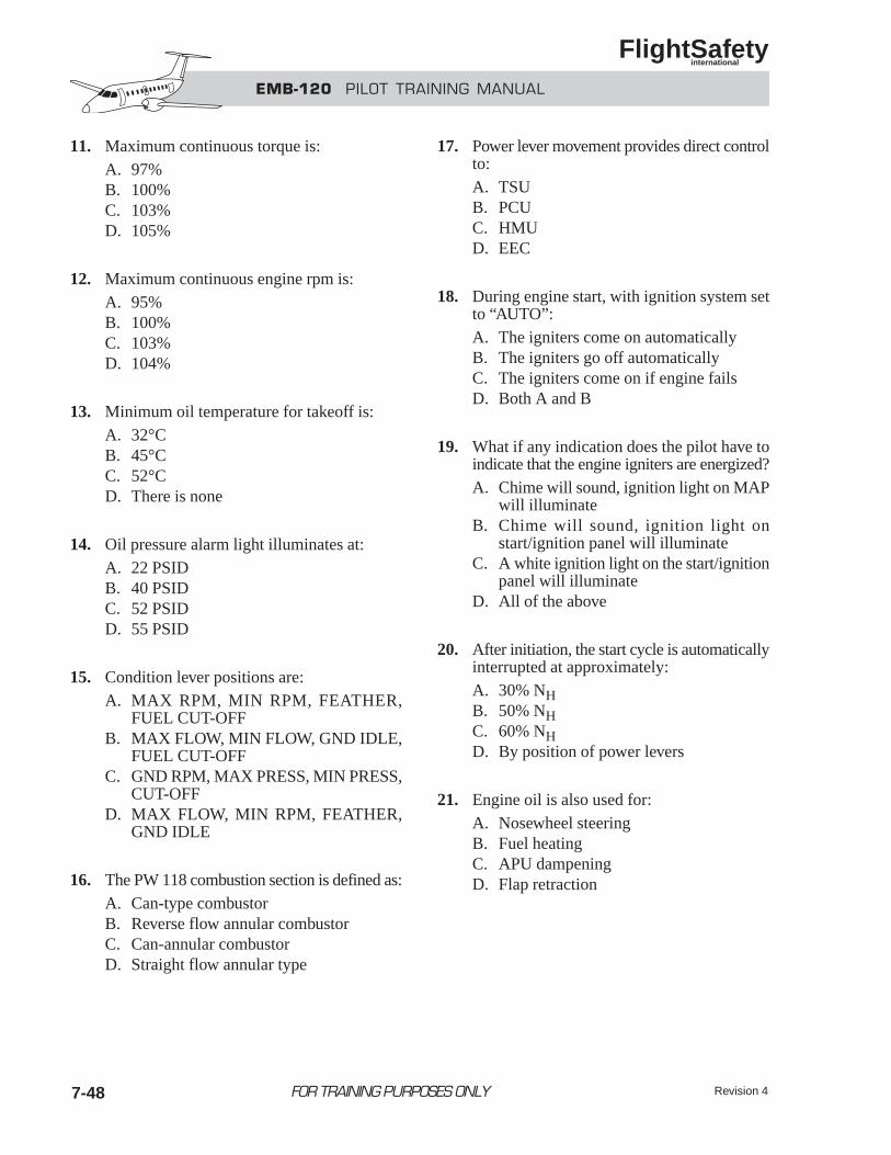
EMB-120 PILOT TRAINING MANUAL
FlightSafety international
FOR TRAINING PURPOSES ONLY Revision 47-48
11. Maximum continuous torque is:A. 97%B. 100%C. 103%D. 105%
12. Maximum continuous engine rpm is:A. 95%B. 100%C. 103%D. 104%
13. Minimum oil temperature for takeoff is:A. 32°CB. 45°CC. 52°CD. There is none
14. Oil pressure alarm light illuminates at:A. 22 PSIDB. 40 PSIDC. 52 PSIDD. 55 PSID
15. Condition lever positions are:A. MAX RPM, MIN RPM, FEATHER,
FUEL CUT-OFFB. MAX FLOW, MIN FLOW, GND IDLE,
FUEL CUT-OFFC. GND RPM, MAX PRESS, MIN PRESS,
CUT-OFFD. MAX FLOW, MIN RPM, FEATHER,
GND IDLE
16. The PW 118 combustion section is defined as:A. Can-type combustorB. Reverse flow annular combustorC. Can-annular combustorD. Straight flow annular type
17. Power lever movement provides direct controlto:A. TSUB. PCUC. HMUD. EEC
18. During engine start, with ignition system setto “AUTO”:A. The igniters come on automaticallyB. The igniters go off automaticallyC. The igniters come on if engine failsD. Both A and B
19. What if any indication does the pilot have toindicate that the engine igniters are energized?A. Chime will sound, ignition light on MAP
will illuminateB. Chime will sound, ignition light on
start/ignition panel will illuminateC. A white ignition light on the start/ignition
panel will illuminateD. All of the above
20. After initiation, the start cycle is automaticallyinterrupted at approximately:A. 30% NHB. 50% NHC. 60% NHD. By position of power levers
21. Engine oil is also used for:A. Nosewheel steeringB. Fuel heatingC. APU dampeningD. Flap retraction
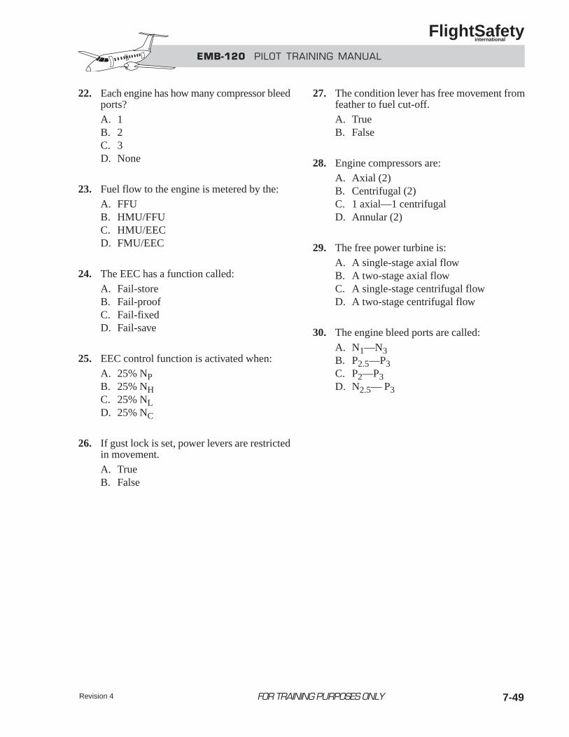
EMB-120 PILOT TRAINING MANUAL
FlightSafety international
FOR TRAINING PURPOSES ONLYRevision 4 7-49
22. Each engine has how many compressor bleedports?A. 1B. 2C. 3D. None
23. Fuel flow to the engine is metered by the:A. FFUB. HMU/FFUC. HMU/EECD. FMU/EEC
24. The EEC has a function called:A. Fail-storeB. Fail-proofC. Fail-fixedD. Fail-save
25. EEC control function is activated when:A. 25% NPB. 25% NHC. 25% NLD. 25% NC
26. If gust lock is set, power levers are restrictedin movement.A. TrueB. False
27. The condition lever has free movement fromfeather to fuel cut-off.A. TrueB. False
28. Engine compressors are:A. Axial (2)B. Centrifugal (2)C. 1 axial—1 centrifugalD. Annular (2)
29. The free power turbine is:A. A single-stage axial flowB. A two-stage axial flowC. A single-stage centrifugal flowD. A two-stage centrifugal flow
30. The engine bleed ports are called:A. N1—N3B. P2.5—P3C. P2—P3D. N2.5— P3
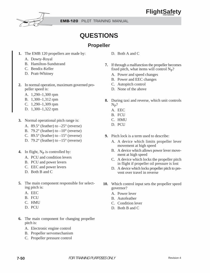
EMB-120 PILOT TRAINING MANUAL
FlightSafety international
FOR TRAINING PURPOSES ONLY Revision 47-50
1. The EMB 120 propellers are made by:A. Dowty-RoyalB. Hamilton-SundstrandC. Bendix-KellerD. Pratt-Whitney
2. In normal operation, maximum governed pro-peller speed is:A. 1,290–1,300 rpmB. 1,300–1,312 rpmC. 1,290–1,309 rpmD. 1,300–1,322 rpm
3. Normal operational pitch range is:A. 89.5° (feather) to –25° (reverse)B. 79.2° (feather) to –10° (reverse)C. 89.5° (feather) to –15° (reverse)D. 79.2° (feather) to –15° (reverse)
4. In flight, NP is controlled by:A. PCU and condition leversB. PCU and power leversC. EEC and power leversD. Both B and C
5. The main component responsible for select-ing pitch is:A. EECB. FCUC. HMUD. PCU
6. The main component for changing propellerpitch is:A. Electronic engine controlB. Propeller servomechanismC. Propeller pressure control
D. Both A and C
7. If through a malfunction the propeller becomesfixed pitch, what items will control NP?A. Power and speed changesB. Power and EEC changesC. Autopitch controlD. None of the above
8. During taxi and reverse, which unit controlsNP?A. EECB. FCUC. HMUD. PCU
9. Pitch lock is a term used to describe:A. A device which limits propeller lever
movement at high speedB. A device which allows power lever move-
ment at high speedC. A device which locks the propeller pitch
in flight if propeller oil pressure is lostD. A device which locks propeller pitch to pre-
vent over travel in reverse
10. Which control input sets the propeller speed governor?A. Power leverB. AutofeatherC. Condition leverD. Both B and C
QUESTIONSPropeller
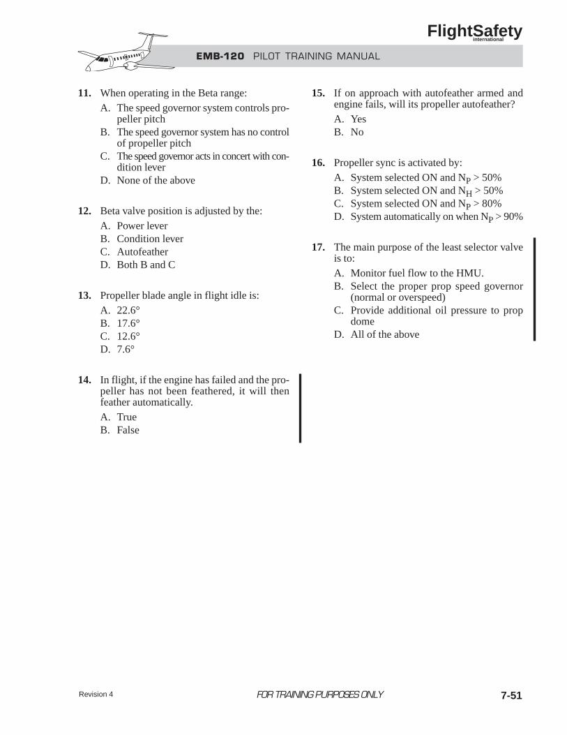
11. When operating in the Beta range:A. The speed governor system controls pro-
peller pitchB. The speed governor system has no control
of propeller pitchC. The speed governor acts in concert with con-
dition leverD. None of the above
12. Beta valve position is adjusted by the:A. Power leverB. Condition leverC. AutofeatherD. Both B and C
13. Propeller blade angle in flight idle is:A. 22.6°B. 17.6°C. 12.6°D. 7.6°
14. In flight, if the engine has failed and the pro-peller has not been feathered, it will thenfeather automatically.A. TrueB. False
15. If on approach with autofeather armed andengine fails, will its propeller autofeather?A. YesB. No
16. Propeller sync is activated by:A. System selected ON and NP > 50%B. System selected ON and NH > 50%C. System selected ON and NP > 80%D. System automatically on when NP > 90%
17. The main purpose of the least selector valveis to:A. Monitor fuel flow to the HMU.B. Select the proper prop speed governor
(normal or overspeed)C. Provide additional oil pressure to prop
domeD. All of the above
Revision 4 7-51FOR TRAINING PURPOSES ONLY
EMB-120 PILOT TRAINING MANUAL
FlightSafety international
Revision 3 8-i
CHAPTER 8FIRE PROTECTION
CONTENTS
Page
INTRODUCTION ................................................................................................................... 8-1
GENERAL............................................................................................................................... 8-1
DETECTION SYSTEMS ........................................................................................................ 8-2
Engine/Wheel Well Fire Detection System...................................................................... 8-2
APU Fire Detection System ............................................................................................. 8-4
Fire Detection Systems Test ............................................................................................. 8-5
Smoke Detection System ................................................................................................. 8-6
FIRE EXTINGUISHING SYSTEMS...................................................................................... 8-7
Engine/Wheel Well Fire Extinguishing System............................................................... 8-7
APU Fire Extinguishing System .................................................................................... 8-10
Portable Fire Extinguishers............................................................................................ 8-11
ELECTRICAL POWER SOURCES..................................................................................... 8-11
Smoke Detection System (Optional).............................................................................. 8-13
Class-C Baggage Compartment Smoke Detection andFire-Extinguishing System (Optional) ........................................................................... 8-14
QUESTIONS ......................................................................................................................... 8-16
FOR TRAINING PURPOSES ONLY
EMB-120 PILOT TRAINING MANUAL
FlightSafety international
Revision 3 8-iii
ILLUSTRATIONS
Figure Title Page
8-1 Engine/Wheel Well Fire Detector Location ............................................................. 8-2
8-2 Fire Detector ............................................................................................................ 8-2
8-3 Engine Fire Control Panel ........................................................................................ 8-3
8-4 APU Fire Detection .................................................................................................. 8-4
8-5 APU Warning and Indicator Lights .......................................................................... 8-5
8-6 Smoke Detector Location ......................................................................................... 8-6
8-7 Selector Switch......................................................................................................... 8-6
8-8 Fire Extinguisher Bottle (Left) ................................................................................. 8-7
8-9 Engine Fire Extinguishing Controls and Indicators.................................................. 8-8
8-10 Engine/Wheel Well Fire Extinguishing System ....................................................... 8-9
8-11 APU Fire Extinguishing System and Controls ....................................................... 8-10
8-12 Fire Protection Controls and Indicators.................................................................. 8-12
8-13 Smoke Detector Locations ..................................................................................... 8-13
8-14 Smoke Detector Panel (Right Closet—Typical)..................................................... 8-14
8-15 Baggage Detection/Extinguishing Panel ................................................................ 8-15
FOR TRAINING PURPOSES ONLY
EMB-120 PILOT TRAINING MANUAL
FlightSafety international
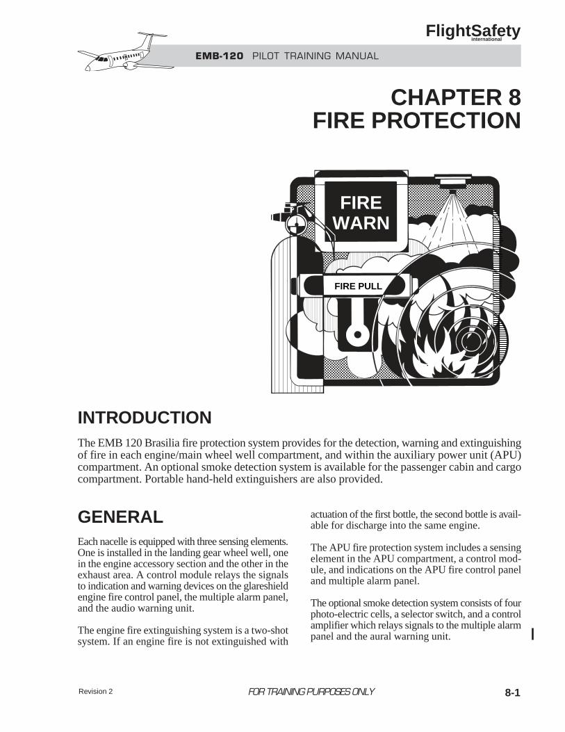
Revision 2 8-1
INTRODUCTIONThe EMB 120 Brasilia fire protection system provides for the detection, warning and extinguishingof fire in each engine/main wheel well compartment, and within the auxiliary power unit (APU)compartment. An optional smoke detection system is available for the passenger cabin and cargocompartment. Portable hand-held extinguishers are also provided.
GENERALEach nacelle is equipped with three sensing elements.One is installed in the landing gear wheel well, onein the engine accessory section and the other in theexhaust area. A control module relays the signalsto indication and warning devices on the glareshieldengine fire control panel, the multiple alarm panel,and the audio warning unit.
The engine fire extinguishing system is a two-shotsystem. If an engine fire is not extinguished with
actuation of the first bottle, the second bottle is avail-able for discharge into the same engine.
The APU fire protection system includes a sensingelement in the APU compartment, a control mod-ule, and indications on the APU fire control paneland multiple alarm panel.
The optional smoke detection system consists of fourphoto-electric cells, a selector switch, and a controlamplifier which relays signals to the multiple alarmpanel and the aural warning unit.
FIRE PULL
FIREWARN
FOR TRAINING PURPOSES ONLY
EMB-120 PILOT TRAINING MANUAL
FlightSafety international
CHAPTER 8FIRE PROTECTION
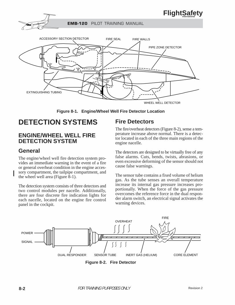
EMB-120 PILOT TRAINING MANUAL
FlightSafety international
8-2
DETECTION SYSTEMS
ENGINE/WHEEL WELL FIREDETECTION SYSTEM
GeneralThe engine/wheel well fire detection system pro-vides an immediate warning in the event of a fireor general overheat condition in the engine acces-sory compartment, the tailpipe compartment, andthe wheel well area (Figure 8-1).
The detection system consists of three detectors andtwo control modules per nacelle. Additionally,there are four discrete fire indication lights foreach nacelle, located on the engine fire controlpanel in the cockpit.
Fire DetectorsThe fire/overheat detectors (Figure 8-2), sense a tem-perature increase above normal. There is a detec-tor located in each of the three main regions of theengine nacelle.
The detectors are designed to be virtually free of anyfalse alarms. Cuts, bends, twists, abrasions, oreven excessive deforming of the sensor should notcause false warnings.
The sensor tube contains a fixed volume of heliumgas. As the tube senses an overall temperatureincrease its internal gas pressure increases pro-portionally. When the force of the gas pressureovercomes the reference force in the dual respon-der alarm switch, an electrical signal activates thewarning devices.
FOR TRAINING PURPOSES ONLY
EXTINGUISHING TUBING
ACCESSORY SECTION DETECTOR FIRE SEAL FIRE WALLS
PIPE ZONE DETECTOR
WHEEL WELL DETECTOR
Figure 8-1. Engine/Wheel Well Fire Detector Location
DUAL RESPONDER SENSOR TUBE INERT GAS (HELIUM) CORE ELEMENT
FIREOVERHEAT
POWER
SIGNAL
Figure 8-2. Fire Detector
Revision 2


![Untitled-2 [sigmatools.ro] · BRASILIA BRASILIA MB (alb) 13 11.200 4300 37 0,45 / 0,87 2240 500 / 813 20,5 BRASILIA BRASILIA Ml (inox) 13 11.200 4300 37 13 + 0,45 / 0,87 2240 500](https://img.pdfslide.us/doc/110x75/5f1f6abc04be014e523cb13b/untitled-2-brasilia-brasilia-mb-alb-13-11200-4300-37-045-087-2240-500.jpg)