Embed Size (px)
Citation preview
EM38pro
1745 Meyerside Drive, Mississauga, Ontario, Canada L5T 1C6Tel: (905) 670 9580 Fax: (905) 670 9204
E-mail: [email protected]
Geonics Limited
November, 2001
Version 1.02
EM38pro DATA LOGGING SYSTEMFOR FIELD COMPUTER Pro4000
OPERATING INSTRUCTIONS

Table of Contents1. Introduction ................................................................................................ 12. Program Requirements ................................................................................. 2 2.1 Contents of EM38pro disk ................................................................... 23. Installing EM38pro ...................................................................................... 24. Running EM38pro Program .......................................................................... 35. Main Menu................................................................................................. 4 5.1 Short description of Main menu options ................................................. 46. Monitor/Null Menu ..................................................................................... 57. Logger SetUp Menu .................................................................................... 68. Set Port for GPS .......................................................................................... 9 8.1 Monitoring GPS Receiver Output ......................................................... 10 8.2 Sending NMEA Message to GPS Receiver ............................................ 119. Acquiring Data Menu and Logging ............................................................... 13 9.1 Create File Menu ............................................................................... 13 9.2 Survey SetUp Menu ............................................................................ 14 9.3 Survey SetUps .................................................................................... 18 9.4 LOG DATA Menu ............................................................................... 19
Stand By Mode ................................................................................... 20Logging Mode.................................................................................... 21
9.5 Field Options ..................................................................................... 2310. Data Transfer (Upload Files) ....................................................................... 27 10.1 Data File Formats ............................................................................. 27 10.2 Upload Files Procedure ..................................................................... 2711. View Files ................................................................................................. 3112. Delete Files ............................................................................................... 3213. End Program............................................................................................. 32Appendix A ....................................................................................................... 33 A.1 Using the EM38pro with a GPS System ................................................ 33 A.2 Description of GGA and GSA Data Messages ...................................... 34Appendix B ....................................................................................................... 35 B.1 Description of Data File in EM38pro Format ......................................... 35 B.2 Example of File in EM38pro Format ..................................................... 38Appendix C ...................................................................................................... 39 C.1 Short Overview of Programs Lynx and ProShell ..................................... 39 C.2 Establishing Communication ............................................................... 39 C.3 Transferring Files to the Pro4000 from the PC....................................... 39 C.4 Transferring Files from the Pro4000 to the PC....................................... 40

1EM38pro Data Logging System (DL4000/38)
1. Introduction1. Introduction1. Introduction1. Introduction1. Introduction
The Geonics EM38pro Data Logging System (DL4000/38) consists of a field computer Pro4000,data logging program EM38pro, and associated cable to connect the Polycorder to the GeonicsEM38RT instrument. The program EM38pro is designed for the Pro4000 field computer, although,if necessary it can be used with any other IBM compatible computer running a MS DOS operatingsystem and equipped with serial port. (i.e. Allegro Field PC.) The only disadvantage of using astandard laptop computer, will be small size of the display which is limited for the Pro4000. Thisdocumentation describes the use of the EM38pro program used with the Pro4000 field computer,and the Geonics EM38RT.
The program EM38pro records data together with a time stamp at each station. Data files createdwith this program can be used to position a survey according to locations recorded separately by aGlobal Positioning System (GPS).
The EM38pro will also accept NMEA-0183 compatible data from a GPS receiver directly connectedto a Pro4000 field computer. GPS data which are embedded in the EM38pro data file can beprocessed later in the Geonics DAT38W program. The connected GPS must be able to streamNMEA-0183 compatible messages. The EM38pro uses two NMEA messages GGA and GSA.While message GGA is mandatory, the GSA string is used only to provide information related tothe GPS signal quality.
Program EM38pro acquires and records survey data from the EM38RT system, under the controlof the operator. It also records various field information such as survey line number (line name),starting station, increment, comments, etc. Readings can be displayed in text or graphic mode.Readings are displayed in real time in mS/m or ppt. In addition, the program allows you to monitorthe instrument output while data are not recorded. The EM38pro also continuously monitors theEM38 measured component (Conductivity or Inphase), dipole mode (Vertical or Horizontal),instrument scale (100 or 1000), and state of fiducial marker without leaving the program.
The program allows the user to set the EM38pro into a specific instrument mode of operation:AUTO, Wheel, or Manual modes. In AUTO mode readings can be automatically recorded in desiredtime intervals. In Wheel mode readings are triggered by a counter installed at the wheel assembly,and in MANUAL mode readings are triggered manually by the operator. In AUTO and Wheelmodes the program can record one combination of the EM38 component (Conductivity or Inphase)and dipole mode (Vertical or Horizontal) per station. In Manual mode any combination ofcomponents and dipole modes can be taken at each station, and data can be averaged at up to 99samples per reading.
Survey setup parameters are saved in a file, therefore they can be automatically used during subsequentdata collection sessions. In addition, ten preset survey setups are provided. These setups are userselectable, they can be edited and saved for future use.
In addition to logging EM38pro data, the EM38pro provides data file management tasks. Theprogram allows you to upload data files to a PC running the DAT38W program. It also has optionsallowing viewing and deleting data files. Data files are always saved to the programs current directory.Data file names, which can be set by the program based on the computer clock or they are userspecified, have extension names R38.
2 Geonics Limited
Over 350,000 readings can be collected in the field computer Pro4000 with the standard memoryof 8 Mb. The maximum speed of data collection is approximately 10 readings per second in textmode, and 9 readings per second in graphic display mode. In graphic display mode, the profilecontaining the last 84 (or 140 in Allegro) data readings for each channel is displayed.
2. P2. P2. P2. P2. Program Rrogram Rrogram Rrogram Rrogram Requirementsequirementsequirementsequirementsequirements
To successfully use this software, you will need :
ComputerField computer Pro4000 or Allegro
or alternatively:- IBM PC and compatibles,- Minimum 640 Kbytes of available memory,- DOS 3.1 or higher,- Floppy drive or other mean to transfer files,- CGA graphics capability,- One Serial Port- optionally, Two Serial Ports if directly connected GPS system is to be used.
Geonics EM61MK2The EM38RT instrument with associated cables.
2.1 Contents of EM38pro disk2.1 Contents of EM38pro disk2.1 Contents of EM38pro disk2.1 Contents of EM38pro disk2.1 Contents of EM38pro diskThe program EM38pro is stored on one 3.5" floppy disk. All necessary initial files (with extensionnames .INI) are created in your computer after the program is run for the first time. Check that thefile EM38pro.EXE is included on the floppy disk.
3. Installing EM38pro3. Installing EM38pro3. Installing EM38pro3. Installing EM38pro3. Installing EM38pro
While using the Pro4000, Allegro, or other field computer which is not equipped with a floppydrive disk, the EM38pro.EXE file should be transferred from a PC computer using software andserial cable provided by manufacturer.
On other computers the EM38pro program can be installed by copying the EM38pro.EXE file toa directory on your hard disk. This can be performed by using Windows Explorer or at DOSprompt (described below). It is assumed that A: indicates floppy drive, and C: indicates hard diskdrive.
A directory (i.e. EM38) can be created with the command MD from DOS.
3EM38pro Data Logging System (DL4000/38)
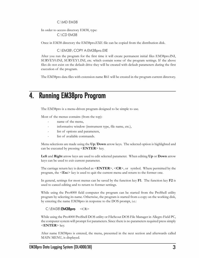
C:\MD EM38
In order to access directory EM38, type:C:\CD EM38
Once in EM38 directory the EM38pro.EXE file can be copied from the distribution disk.
C:\EM38\ COPY A:EM38pro.EXE
After you run the program for the first time it will create permanent initial files EM38pro.INI,SURVEY0.INI, SURVEY1.INI, etc. which contain some of the program settings. If the abovefiles do not exist on the default drive they will be created with default parameters during the firstexecution of the program.
The EM38pro data files with extension name R61 will be created in the program current directory.
4. R4. R4. R4. R4. Running EM38pro Punning EM38pro Punning EM38pro Punning EM38pro Punning EM38pro Programrogramrogramrogramrogram
The EM38pro is a menu-driven program designed to be simple to use.
Most of the menus contains (from the top):- name of the menu,- informative window (instrument type, file name, etc.),- list of options and parameters,- list of available commands.
Menu selections are made using the Up/Down arrow keys. The selected option is highlighted andcan be executed by pressing <ENTER> key.
Left and Right arrow keys are used to edit selected parameter. When editing Up or Down arrowkeys can be used to exit current parameter.
The carriage return key is described as <ENTER>, <CR>, or symbol. Where permitted by theprogram, the <Esc> key is used to quit the current menu and return to the former one.
In general, settings for most menus can be saved by the function key F1. The function key F2 isused to cancel editing and to return to former settings.
While using the Pro4000 field computer the program can be started from the ProShell utilityprogram by selecting its name. Otherwise, the program is started from a copy on the working disk,by entering the name EM38pro in response to the DOS prompt, i.e.:
C:\EM38\EM38proEM38proEM38proEM38proEM38pro <CR>
While using the Pro4000 ProShell DOS utility or FileScout DOS File Manager in Allegro Field PC,the computer system will prompt for parameters. Since there is no parameters required press simply<ENTER> key.
After name EM38pro is entered, the menu, presented in the next section and afterwards calledMAIN MENU, is displayed.
4 Geonics Limited
5. Main Menu5. Main Menu5. Main Menu5. Main Menu5. Main Menu
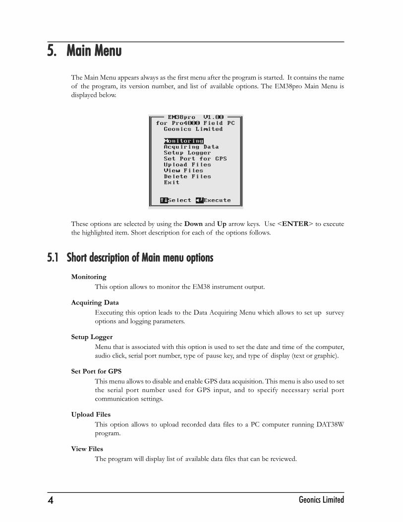
The Main Menu appears always as the first menu after the program is started. It contains the nameof the program, its version number, and list of available options. The EM38pro Main Menu isdisplayed below.
These options are selected by using the Down and Up arrow keys. Use <ENTER> to executethe highlighted item. Short description for each of the options follows.
5.1 Short description of Main menu options5.1 Short description of Main menu options5.1 Short description of Main menu options5.1 Short description of Main menu options5.1 Short description of Main menu optionsMonitoring
This option allows to monitor the EM38 instrument output.
Acquiring DataExecuting this option leads to the Data Acquiring Menu which allows to set up surveyoptions and logging parameters.
Setup LoggerMenu that is associated with this option is used to set the date and time of the computer,audio click, serial port number, type of pause key, and type of display (text or graphic).
Set Port for GPSThis menu allows to disable and enable GPS data acquisition. This menu is also used to setthe serial port number used for GPS input, and to specify necessary serial portcommunication settings.
Upload FilesThis option allows to upload recorded data files to a PC computer running DAT38Wprogram.
View FilesThe program will display list of available data files that can be reviewed.
5EM38pro Data Logging System (DL4000/38)
Delete FilesThis option allows to delete permanently not needed data files from the field computerdisk.
ExitSelecting this option will terminate the program execution.
6. Monitoring6. Monitoring6. Monitoring6. Monitoring6. Monitoring
The Monitoring menu allows initial inspection of the range of the instrument readings at theparticular site, monitoring the instrument performance, and quick inspection of the instrumentsettings.
It is assumed that the instrument is turned ON prior to using this option. In case the instrument isOFF or the instrument console is not connected to the computer the following message will appear:
Check the connection or turn the instrument ON and select the Monitoring option again.
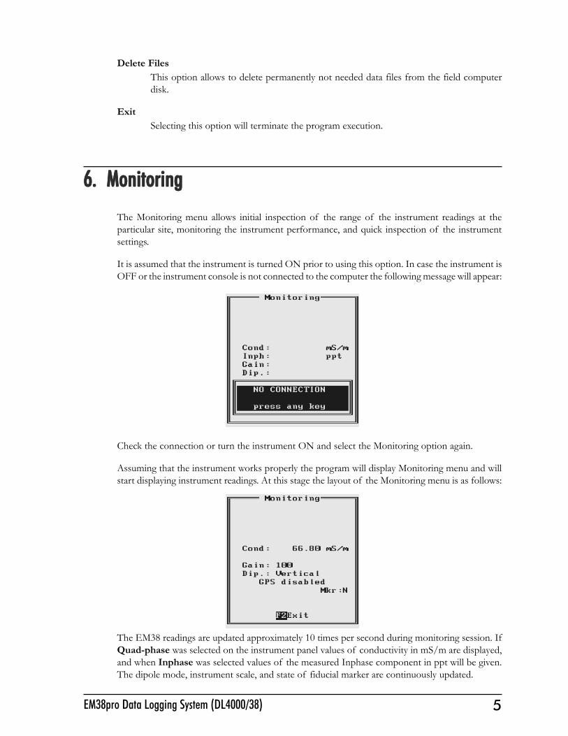
Assuming that the instrument works properly the program will display Monitoring menu and willstart displaying instrument readings. At this stage the layout of the Monitoring menu is as follows:
The EM38 readings are updated approximately 10 times per second during monitoring session. IfQuad-phase was selected on the instrument panel values of conductivity in mS/m are displayed,and when Inphase was selected values of the measured Inphase component in ppt will be given.The dipole mode, instrument scale, and state of fiducial marker are continuously updated.
6 Geonics Limited
When GPS was Disabled in the Set Port for GPS menu a message GPS Disabled will be displayed.If the GPS port is Enabled and a working GPS system is connected to the field computer theMonitoring screen will display a few more parameters, as presented below.
In the above Figure one line of the display is dedicated to show the GPS status. A label DGPS(Differential Global Positioning System) indicates that GPS readings are differentially corrected inreal time, while label AGPS (Autonomous Global Positioning System) indicates lack of differentialcorrection. On the right side of DGPS or AGPS label small square is displayed. This square shouldmove down and up with the frequency of GPS update rate (usually 1 second intervals). If thesquare is not moving for long periods of time it means that the GPS system is not working or thatit is not connected to the field computer. The next label P with a value varying between 0 and 99.9represents an index called Position Dilution of Precision (PDOP). The last label S and followingnumber shows number of currently tracked satellites. Refer to section 9 (Set Port for GPS), AppendixA, and to GPS manuals for more information about GPS parameters.
To exit the Monitoring option press the function key F2.
7. Logger Setup Menu7. Logger Setup Menu7. Logger Setup Menu7. Logger Setup Menu7. Logger Setup Menu
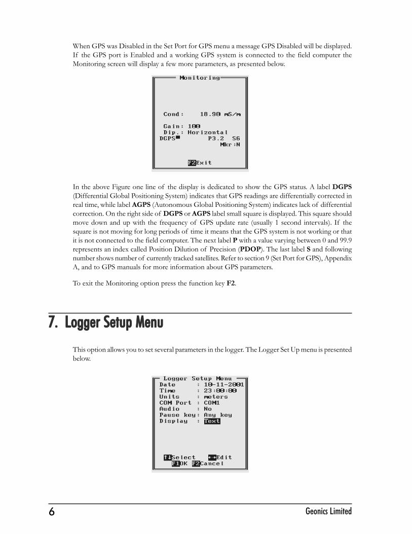
This option allows you to set several parameters in the logger. The Logger Set Up menu is presentedbelow.
7EM38pro Data Logging System (DL4000/38)
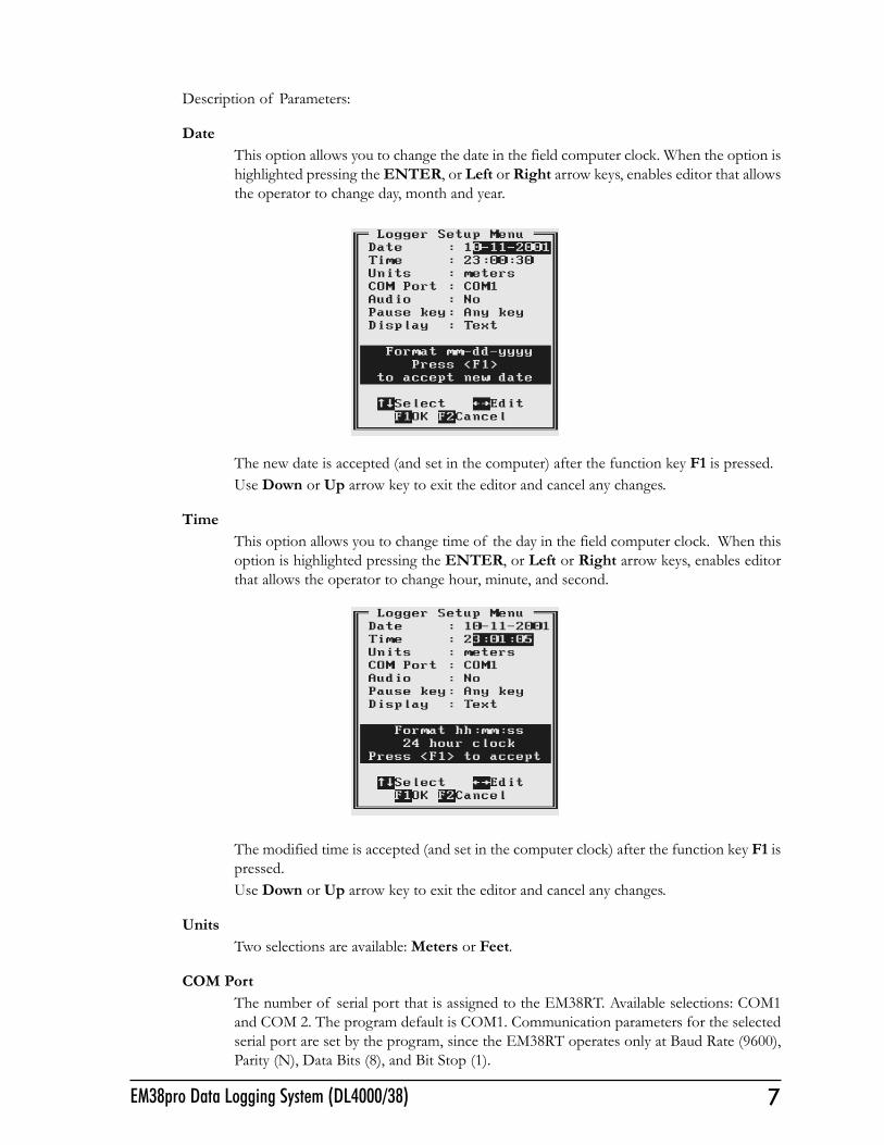
Description of Parameters:
DateThis option allows you to change the date in the field computer clock. When the option ishighlighted pressing the ENTER, or Left or Right arrow keys, enables editor that allowsthe operator to change day, month and year.
The new date is accepted (and set in the computer) after the function key F1 is pressed.Use Down or Up arrow key to exit the editor and cancel any changes.
TimeThis option allows you to change time of the day in the field computer clock. When thisoption is highlighted pressing the ENTER, or Left or Right arrow keys, enables editorthat allows the operator to change hour, minute, and second.
The modified time is accepted (and set in the computer clock) after the function key F1 ispressed.Use Down or Up arrow key to exit the editor and cancel any changes.
UnitsTwo selections are available: Meters or Feet.
COM PortThe number of serial port that is assigned to the EM38RT. Available selections: COM1and COM 2. The program default is COM1. Communication parameters for the selectedserial port are set by the program, since the EM38RT operates only at Baud Rate (9600),Parity (N), Data Bits (8), and Bit Stop (1).
8 Geonics Limited
This port must be different than the port specified in the Set Port for GPS menu (seenext), otherwise a message will be displayed and ports will have to be reassigned.The serial port selected here is also used for uploading data files to the PC.
AudioTwo selections are available: Yes or No. The audible click will be generated at each readingwhen this option is enabled.
Pause keyThree selections are available: Any key, Alt+F1, and Ctrl+F5. This feature is used topause data recording during logging session. Default setting Any key can be changed toone of the two key combinations for field conditions where a logger key can be accidentallypushed causing unwanted stop of data logging.
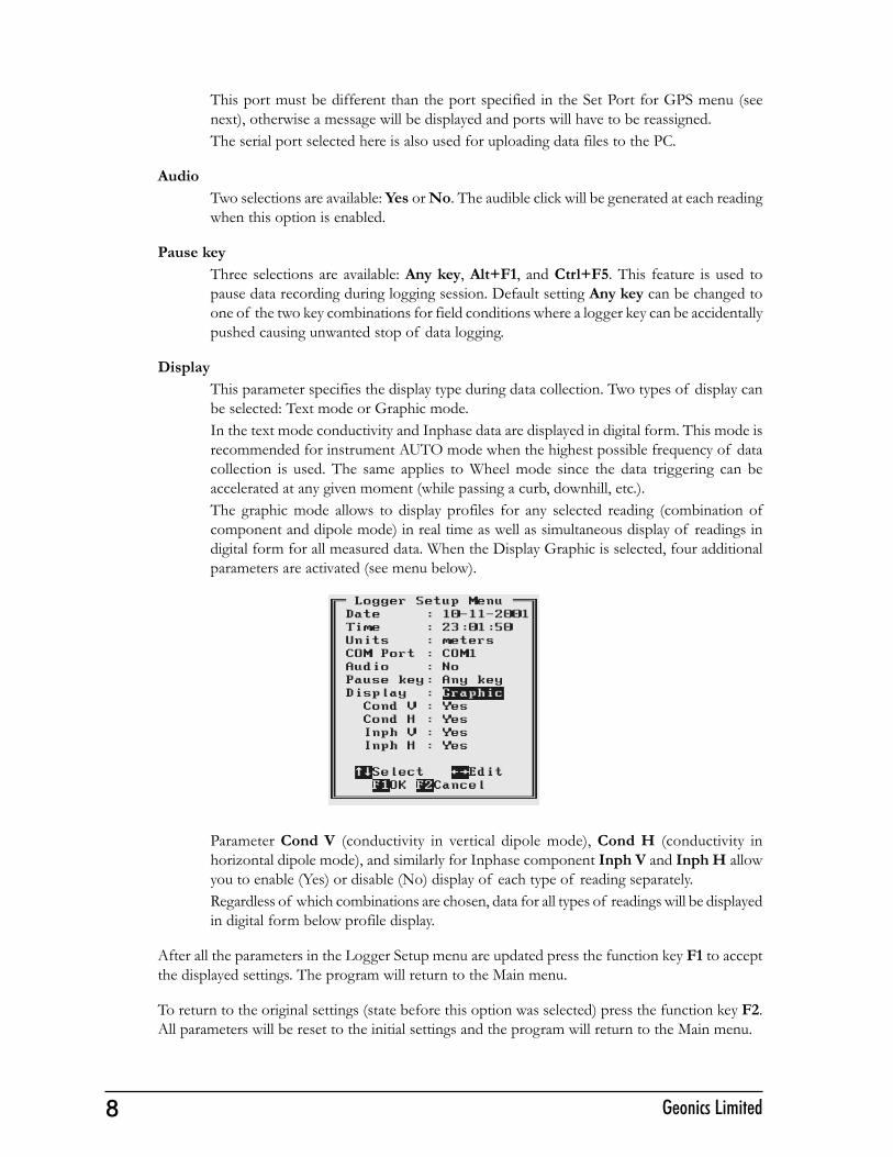
DisplayThis parameter specifies the display type during data collection. Two types of display canbe selected: Text mode or Graphic mode.In the text mode conductivity and Inphase data are displayed in digital form. This mode isrecommended for instrument AUTO mode when the highest possible frequency of datacollection is used. The same applies to Wheel mode since the data triggering can beaccelerated at any given moment (while passing a curb, downhill, etc.).The graphic mode allows to display profiles for any selected reading (combination ofcomponent and dipole mode) in real time as well as simultaneous display of readings indigital form for all measured data. When the Display Graphic is selected, four additionalparameters are activated (see menu below).
Parameter Cond V (conductivity in vertical dipole mode), Cond H (conductivity inhorizontal dipole mode), and similarly for Inphase component Inph V and Inph H allowyou to enable (Yes) or disable (No) display of each type of reading separately.Regardless of which combinations are chosen, data for all types of readings will be displayedin digital form below profile display.
After all the parameters in the Logger Setup menu are updated press the function key F1 to acceptthe displayed settings. The program will return to the Main menu.
To return to the original settings (state before this option was selected) press the function key F2.All parameters will be reset to the initial settings and the program will return to the Main menu.
9EM38pro Data Logging System (DL4000/38)
8. Set P8. Set P8. Set P8. Set P8. Set Port for GPS Menuort for GPS Menuort for GPS Menuort for GPS Menuort for GPS Menu
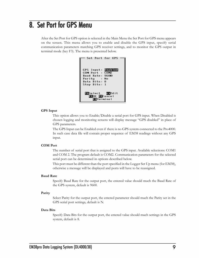
After the Set Port for GPS option is selected in the Main Menu the Set Port for GPS menu appearson the screen. This menu allows you to enable and disable the GPS input, specify serialcommunication parameters matching GPS receiver settings, and to monitor the GPS output interminal mode (key F3). The menu is presented below.
GPS InputThis option allows you to Enable/Disable a serial port for GPS input. When Disabled ischosen logging and monitoring screens will display message �GPS disabled� in place ofGPS parameters.The GPS Input can be Enabled even if there is no GPS system connected to the Pro4000.In such case data file will contain proper sequence of EM38 readings without any GPSinput.
COM PortThe number of serial port that is assigned to the GPS input. Available selections: COM1and COM 2. The program default is COM2. Communication parameters for the selectedserial port can be determined in options described below.This port must be different than the port specified in the Logger Set Up menu (for EM38),otherwise a message will be displayed and ports will have to be reassigned.
Baud RateSpecify Baud Rate for the output port, the entered value should much the Baud Rate ofthe GPS system, default is 9600.
ParitySelect Parity for the output port, the entered parameter should much the Parity set in theGPS serial port settings, default is N.
Data BitsSpecify Data Bits for the output port, the entered value should much settings in the GPSsystem, default is 8.
10 Geonics Limited
Stop BitsSpecify Stop Bits for the output port, the entered value should much settings in the GPSsystem, default is 1.
After all the parameters in the Logger Setup menu are updated press the function key F1 to acceptthe displayed settings. The program will return to the Main menu.
To return to the original settings (state before this option was selected) press the function key F2.All parameters will be reset to the initial settings and the program will return to the Main menu.
To activate terminal mode which allows you to monitor GPS receiver output press the function keyF3. The monitoring mode will work regardless of the GPS Input being Enabled or Disabled. Thisoption is described in the following section.
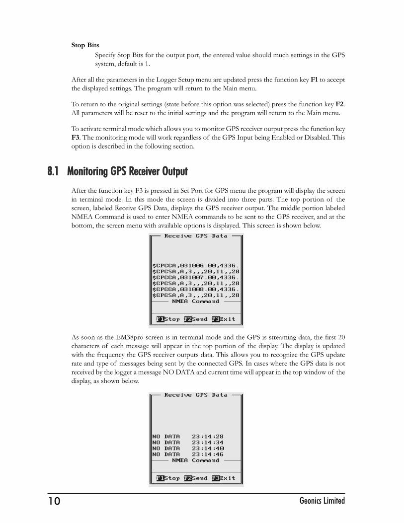
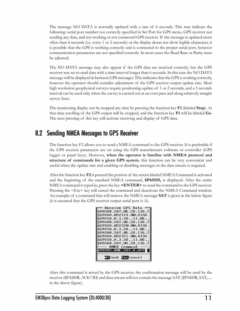
8.1 Monitoring GPS R8.1 Monitoring GPS R8.1 Monitoring GPS R8.1 Monitoring GPS R8.1 Monitoring GPS Receiver Outputeceiver Outputeceiver Outputeceiver Outputeceiver OutputAfter the function key F3 is pressed in Set Port for GPS menu the program will display the screenin terminal mode. In this mode the screen is divided into three parts. The top portion of thescreen, labeled Receive GPS Data, displays the GPS receiver output. The middle portion labeledNMEA Command is used to enter NMEA commands to be sent to the GPS receiver, and at thebottom, the screen menu with available options is displayed. This screen is shown below.
As soon as the EM38pro screen is in terminal mode and the GPS is streaming data, the first 20characters of each message will appear in the top portion of the display. The display is updatedwith the frequency the GPS receiver outputs data. This allows you to recognize the GPS updaterate and type of messages being sent by the connected GPS. In cases where the GPS data is notreceived by the logger a message NO DATA and current time will appear in the top window of thedisplay, as shown below.
11EM38pro Data Logging System (DL4000/38)
The message NO DATA is normally updated with a rate of 6 seconds. This may indicate thefollowing: serial port number not correctly specified in Set Port for GPS menu, GPS receiver notsending any data, and not working or not connected GPS receiver. If the message is updated moreoften than 6 seconds (i.e. every 1 or 2 seconds) or the display doeas not show legible characters, itis possible that the GPS is working correctly and is connected to the proper serial port, howevercommunication parameters are not specified correctly. In most cases the Baud Rate or Parity mustbe adjusted.
The NO DATA message may also appear if the GPS data are received correctly, but the GPSreceiver was set to send data with a time interval longer than 6 seconds. In this case the NO DATAmessage will be displayed in between GPS messages. This indicates that the GPS is working correctly,however the operator should consider adjustment of the GPS receiver output update rate. Mosthigh resolution geophysical surveys require positioning update of 1 or 2 seconds, and a 5 secondsinterval can be used only when the survey is carried out at an even pace and along relatively straightsurvey lines.
The monitoring display can be stopped any time by pressing the function key F1 (labeled Stop). Atthat time scrolling of the GPS output will be stopped, and the function key F1 will be labeled Go.The next pressing of this key will activate receiving and display of GPS data.
8.2 Sending NMEA Messages to GPS R8.2 Sending NMEA Messages to GPS R8.2 Sending NMEA Messages to GPS R8.2 Sending NMEA Messages to GPS R8.2 Sending NMEA Messages to GPS ReceivereceivereceivereceivereceiverThe function key F2 allows you to send a NMEA command to the GPS receiver. It is preferable ifthe GPS receiver parameters are set using the GPS manufacturer software or controller (GPSlogger or panel keys). However, when the operator is familiar with NMEA protocol andstructure of commands for a given GPS system, this function can be very convenient anduseful when the update rate and enabling or disabling messages in the data stream is required.
After the function key F2 is pressed the portion of the screen labeled NMEA Command is activatedand the beginning of the standard NMEA command, $PASHS, is displayed. After the entireNMEA command is typed in, press the key <ENTER> to send the command to the GPS receiver.Pressing the <Esc> key will cancel the command and deactivate the NMEA Command window.An example of a command that will remove the NMEA message SAT is given in the below figure(it is assumed that the GPS receiver output serial port is A).
After this command is reived by the GPS receiver, the confirmation message will be send by thereceiver ($PASHR, ACK*3D) and data stream will not contain the message SAT ($PASHR, SAT,.....in the above figure).

12 Geonics Limited
Please note, that not every GPS system accepts and uses the same standard set of NMEA commandsand messages. In addition, some GPS systems do not accept commands sent by the serial port atall. The configuration of these type of receivers can be updated only by the controlling device(usually GPS logger, controllel, or the receiver panel keys). An example of the latter is widely usedGPS Trimble ProXRS.
13EM38pro Data Logging System (DL4000/38)
9. Acquiring Data Menu and Logging9. Acquiring Data Menu and Logging9. Acquiring Data Menu and Logging9. Acquiring Data Menu and Logging9. Acquiring Data Menu and Logging
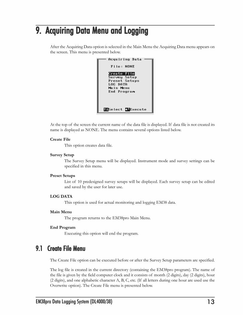
After the Acquiring Data option is selected in the Main Menu the Acquiring Data menu appears onthe screen. This menu is presented below.
At the top of the screen the current name of the data file is displayed. If data file is not created itsname is displayed as NONE. The menu contains several options listed below.
Create FileThis option creates data file.
Survey SetupThe Survey Setup menu will be displayed. Instrument mode and survey settings can bespecified in this menu.
Preset SetupsList of 10 predesigned survey setups will be displayed. Each survey setup can be editedand saved by the user for later use.
LOG DATAThis option is used for actual monitoring and logging EM38 data.
Main MenuThe program returns to the EM38pro Main Menu.
End ProgramExecuting this option will end the program.
9.1 Create File Menu9.1 Create File Menu9.1 Create File Menu9.1 Create File Menu9.1 Create File MenuThe Create File option can be executed before or after the Survey Setup parameters are specified.
The log file is created in the current directory (containing the EM38pro program). The name ofthe file is given by the field computer clock and it consists of month (2 digits), day (2 digits), hour(2 digits), and one alphabetic character A, B, C, etc. (If all letters during one hour are used use theOverwrite option). The Create File menu is presented below.

14 Geonics Limited
The file can be created by pressing the function key F1, this option can be skipped by pressing thefunction key F2., or by pressing key F3 the file name can be overwritten. After key F3 is pressed theCreate File menu will be displayed as follows.
Each data file in the field computer (raw data file) has an extension name R38 and it is created in theprograms current directory. The R38 files are created in the instrument binary format. They can beviewed using the Main menu option �View Files�. These files can be also converted to ASCIIformat and processed in the Geonics program DAT38W and DAT38 (for DOS).
9.2 Survey Setup Menu9.2 Survey Setup Menu9.2 Survey Setup Menu9.2 Survey Setup Menu9.2 Survey Setup MenuThe Survey Setup menu, presented below, contains several parameters which affect two importantprocedures: instrument settings (instrument mode, frequency of data collection, etc.) and surveygeometry layout (survey line names, line spacing, start station, station increment, etc.).
15EM38pro Data Logging System (DL4000/38)
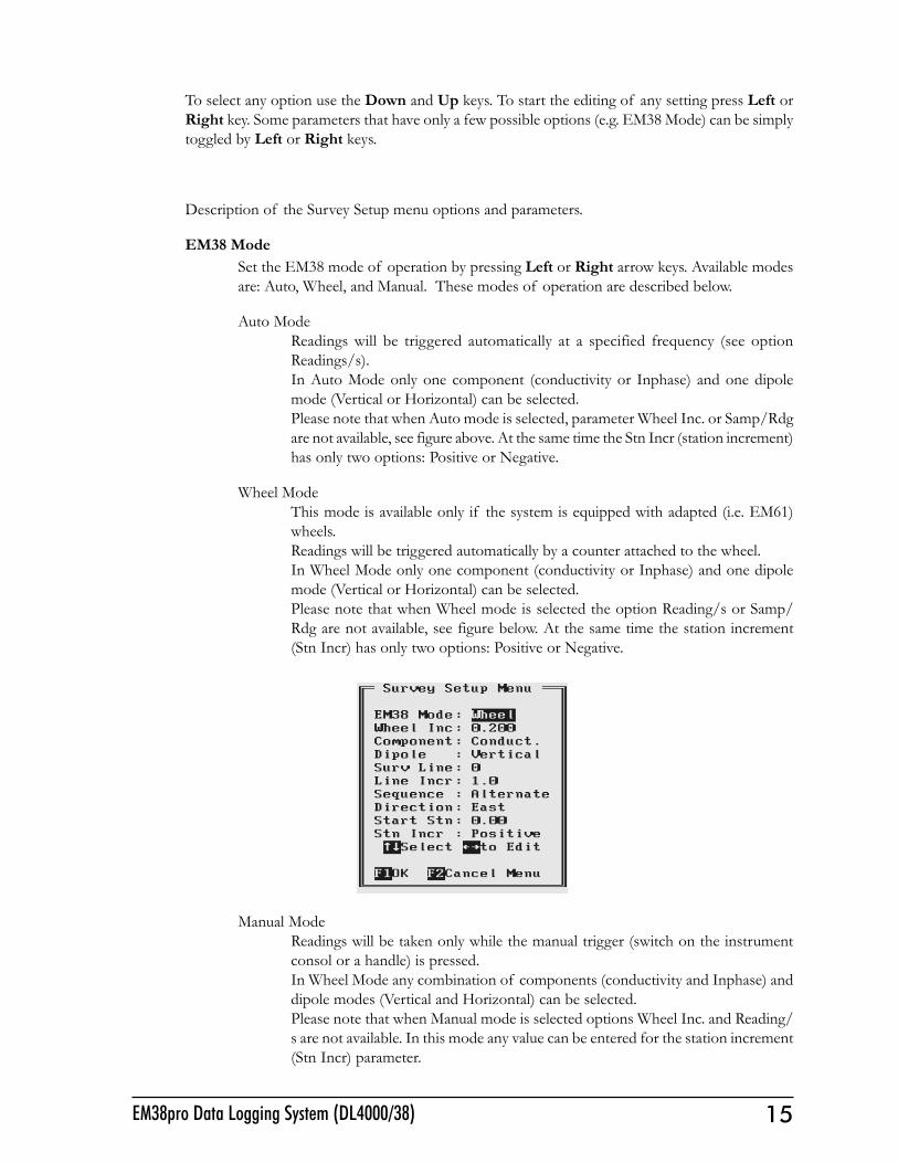
To select any option use the Down and Up keys. To start the editing of any setting press Left orRight key. Some parameters that have only a few possible options (e.g. EM38 Mode) can be simplytoggled by Left or Right keys.
Description of the Survey Setup menu options and parameters.
EM38 ModeSet the EM38 mode of operation by pressing Left or Right arrow keys. Available modesare: Auto, Wheel, and Manual. These modes of operation are described below.
Auto ModeReadings will be triggered automatically at a specified frequency (see optionReadings/s).In Auto Mode only one component (conductivity or Inphase) and one dipolemode (Vertical or Horizontal) can be selected.Please note that when Auto mode is selected, parameter Wheel Inc. or Samp/Rdgare not available, see figure above. At the same time the Stn Incr (station increment)has only two options: Positive or Negative.
Wheel ModeThis mode is available only if the system is equipped with adapted (i.e. EM61)wheels.Readings will be triggered automatically by a counter attached to the wheel.In Wheel Mode only one component (conductivity or Inphase) and one dipolemode (Vertical or Horizontal) can be selected.Please note that when Wheel mode is selected the option Reading/s or Samp/Rdg are not available, see figure below. At the same time the station increment(Stn Incr) has only two options: Positive or Negative.
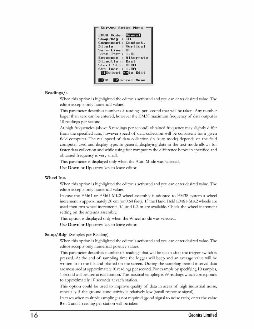
Manual ModeReadings will be taken only while the manual trigger (switch on the instrumentconsol or a handle) is pressed.In Wheel Mode any combination of components (conductivity and Inphase) anddipole modes (Vertical and Horizontal) can be selected.Please note that when Manual mode is selected options Wheel Inc. and Reading/s are not available. In this mode any value can be entered for the station increment(Stn Incr) parameter.
16 Geonics Limited
Readings/sWhen this option is highlighted the editor is activated and you can enter desired value. Theeditor accepts only numerical values.This parameter describes number of readings per second that will be taken. Any numberlarger than zero can be entered, however the EM38 maximum frequency of data output is10 readings per second.At high frequencies (above 5 readings per second) obtained frequency may slightly differfrom the specified rate, however speed of data collection will be consistent for a givenfield computer. The real speed of data collection (in Auto mode) depends on the fieldcomputer used and display type. In general, displaying data in the text mode allows forfaster data collection and while using fast computers the difference between specified andobtained frequency is very small.This parameter is displayed only when the Auto Mode was selected.Use Down or Up arrow key to leave editor.
Wheel Inc.When this option is highlighted the editor is activated and you can enter desired value. Theeditor accepts only numerical values.In case the EM61 or EM61-MK2 wheel assembly is adopted to EM38 system a wheelincrement is approximately 20 cm (or 0.64 feet). If the Hand Held EM61-MK2 wheels areused then two wheel increments 0.1 and 0.2 m are available. Check the wheel incrementsetting on the antenna assembly.This option is displayed only when the Wheel mode was selected.Use Down or Up arrow key to leave editor.
Samp/Rdg (Samples per Reading)When this option is highlighted the editor is activated and you can enter desired value. Theeditor accepts only numerical positive values.This parameter describes number of readings that will be taken after the trigger switch ispressed. At the end of sampling time the logger will beep and an average value will bewritten in to the file and plotted on the screen. During the sampling period interval dataare measured at approximately 10 readings per second. For example by specifying 10 samples,1 second will be used at each station. The maximal sampling is 99 readings which correspondsto approximately 10 seconds at each station.This option could be used to improve quality of data in areas of high industrial noise,especially if the ground conductivity is relatively low (small response signal).In cases when multiple sampling is not required (good signal to noise ratio) enter the value0 or 1 and 1 reading per station will be taken.
17EM38pro Data Logging System (DL4000/38)
This parameter is displayed only when the Manual Mode was selected.Use Down or Up arrow key to leave editor.
ComponentWhen this option is highlighted press Left or Right to toggle between two or three availablesettings: Conductivity, Inphase, and Both.When Manual mode was selected three settings are available: Conductivity, Inphase, andBoth.If Auto or Wheel mode was selected two available dipole modes are: Conductivity orInphase.Use Down or Up arrow key to leave editor.
Dipole (instrument dipole mode)When this option is highlighted press Left or Right to toggle between two or three availablesettings: Vertical, Horizontal, and Both.When Manual mode was selected three settings are available: Vertical, Horizontal, andBoth. If Auto or Wheel mode was selected two available dipole modes are: Vertical orHorizontal.Use Down or Up arrow key to leave editor.
Surv Line (survey line name)When this option is highlighted press Left or Right arrow key to activate editor and thenenter desired value. Use Down or Up arrow key to leave editor.This is a user�s tag number/name for the profile line. The length of the name can notexceed 8 characters. The line name is usually used as a coordinate perpendicular to thesurvey lines direction. For example, when survey lines are laid out along W-E directionstations describe W-E coordinate, while Line names may describe S-N (vertical on a map)coordinate.
Line Incr. (survey line name)When this option is highlighted press Left or Right arrow key to activate editor and thenenter desired value.This parameter specifies the distance by which survey lines will be separated. This settingwill be used to determine number (name) of the next survey line.Use Down or Up arrow key to leave editor.
SequenceWhen this option is highlighted press Left or Right to toggle between two available settings:Alternate and One Way.Alternate is used when neighboring lines are surveyed in the opposite direction, which isthe most common procedure during field surveys.One Way is used when each survey line is traversed in the same direction.The choice of this parameter will affect the default start station, a signature of the stationincrement, and line direction when parameters for the next survey lines is determined.
DirectionWhen this option is highlighted press Left or Right to toggle between four availablesettings: East, West, South, and North.This parameter indicates the heading of the survey line.Use Down or Up arrow key to leave editor.
18 Geonics Limited
Start Stn (start station of a survey line)When this option is highlighted press Left or Right arrow key to activate editor and thenenter desired value.This parameter specifies the starting station number for the selected survey line. Thisvalue is used in conjunction with Station Increment to calculate the current station numberfor display purposes.Use Down or Up arrow key to leave editor.
Stn Incr (station increment)When this option is highlighted press Left or Right arrow key to activate editor.In case the EM38 Manual mode was selected enter desired value for the station increment.If Auto or Wheel modes were selected then, the Left and Right arrow keys will togglebetween two available options: Positive and Negative.This parameter specifies the station increment for the selected survey line. This value isused in conjunction with Start Station to calculate the current station number for displaypurposes.In Auto mode the increment is assumed +1 (Positive) or -1 (Negative), while in Wheelmode it will be Positive or Negative value of the specified Wheel Increment.Use Down or Up arrow key to leave editor.
After all the parameters in the Survey Setup menu are updated press the function key F1 to acceptthe displayed settings. The program will return to the Acquiring Data menu. Updated settings willbe written to the initial file and they will be given as default parameters in the subsequent SurveySetup menu display.
To return to original settings (state before this option was selected) press the function key F2. Allparameters will be reset to initial settings and the program will return to the Acquiring Data menu.
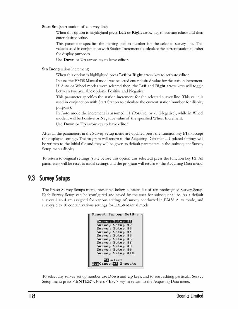
9.3 Survey Setups9.3 Survey Setups9.3 Survey Setups9.3 Survey Setups9.3 Survey SetupsThe Preset Survey Setups menu, presented below, contains list of ten predesigned Survey Setup.Each Survey Setup can be configured and saved by the user for subsequent use. As a defaultsurveys 1 to 4 are assigned for various settings of survey conducted in EM38 Auto mode, andsurveys 5 to 10 contain various settings for EM38 Manual mode.
To select any survey set up number use Down and Up keys, and to start editing particular SurveySetup menu press <ENTER>. Press <Esc> key. to return to the Acquiring Data menu.

19EM38pro Data Logging System (DL4000/38)
After a Survey Setup number (e.g. Survey Set Up #2) is selected the following screen will appear:
The survey parameters are updated in the exactly same way as in the Survey Setup menu (seesection 9.2).
After all parameters are specified three options represented by function keys F1, F2, and F3 areavailable :
F1 (OK)The display returns to Acquiring Data menu. The selection will become the current SurveySetup parameters, however settings will not be saved as a Survey Setup # for subsequentuse.
F2 (Cancel)The display returns to Acquiring Data menu. The selection is cancelled and it will not besaved.
F3 (Save)The selection is saved as a particular Survey Setup number. The display does not return toAcquiring Data menu, nor it becomes the current Survey Setup. In order to use the editedparameters as a current Survey Setup use function key F1.
9.4 L9.4 L9.4 L9.4 L9.4 LOG DOG DOG DOG DOG DAAAAATTTTTA MenuA MenuA MenuA MenuA MenuAfter the Acquiring Data menu option LOG DATA is highlighted press <ENTER> key. It isassumed that the instrument is turned ON prior to using this option. In case instrument is OFF orthe instrument console is not connected to the field computer the message shown below willappear.
20 Geonics Limited
Check the connection or turn the instrument ON and select the LOG DATA option again.
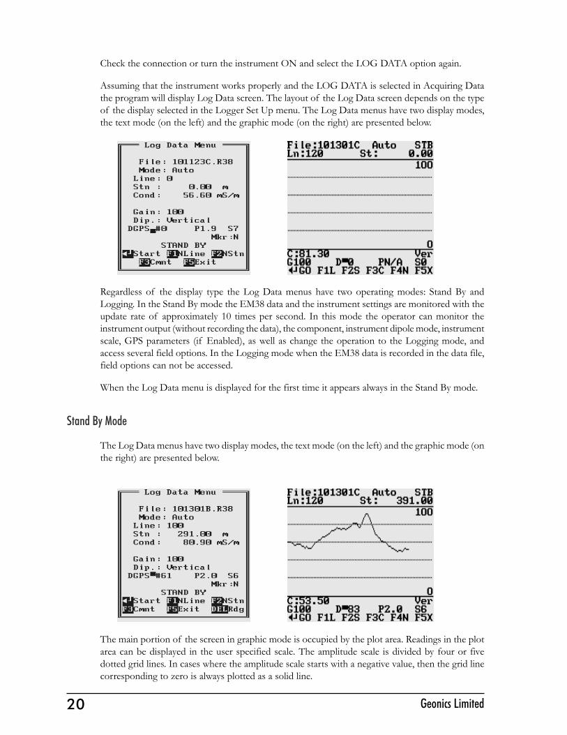
Assuming that the instrument works properly and the LOG DATA is selected in Acquiring Datathe program will display Log Data screen. The layout of the Log Data screen depends on the typeof the display selected in the Logger Set Up menu. The Log Data menus have two display modes,the text mode (on the left) and the graphic mode (on the right) are presented below.
Regardless of the display type the Log Data menus have two operating modes: Stand By andLogging. In the Stand By mode the EM38 data and the instrument settings are monitored with theupdate rate of approximately 10 times per second. In this mode the operator can monitor theinstrument output (without recording the data), the component, instrument dipole mode, instrumentscale, GPS parameters (if Enabled), as well as change the operation to the Logging mode, andaccess several field options. In the Logging mode when the EM38 data is recorded in the data file,field options can not be accessed.
When the Log Data menu is displayed for the first time it appears always in the Stand By mode.
Stand By Mode
The Log Data menus have two display modes, the text mode (on the left) and the graphic mode (onthe right) are presented below.
The main portion of the screen in graphic mode is occupied by the plot area. Readings in the plotarea can be displayed in the user specified scale. The amplitude scale is divided by four or fivedotted grid lines. In cases where the amplitude scale starts with a negative value, then the grid linecorresponding to zero is always plotted as a solid line.
21EM38pro Data Logging System (DL4000/38)
Readings for conductivity or Inphase are shown in digital form in the central portion of the screenin the text mode, and below plot area in the graphic mode. In graphic mode due to small screen ofPro4000 readings are labeled C for conductivity and I for Inphase. Units (mS/m and ppt) are notdisplayed in the graphic mode.
Both modes show the log file name and optional GPS parameters. Name of the Log Data menumode is displayed in the text mode, and it is shown as an abbreviation in the top right corner of thescreen in graphic mode, STB for Stand By mode, and LOG for logging mode. The instrumentcomponent setting, the instrument gain (G in graphic mode), and dipole mode (labeled Ver or Horin graphic mode) are updated continuously in both modes. When the fiducial marker is pressed alabel M will appear on the screen in graphic mode, and Y will be displayed at label Mkr in the textmode..
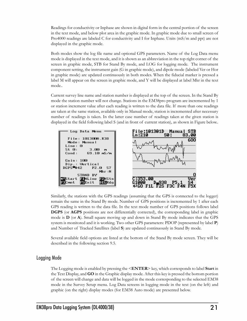
Current survey line name and station number is displayed at the top of the screen. In the Stand Bymode the station number will not change. Stations in the EM38pro program are incremented by 1or station increment value after each reading is written to the data file. If more than one readingsare taken at the same station, available only in Manual mode, station is incremented after necessarynumber of readings is taken. In the latter case number of readings taken at the given station isdisplayed in the field following label S (and in front of current station), as shown in Figure below..
Similarly, the stations with the GPS readings (assuming that the GPS is connected to the logger)remain the same in the Stand By mode. Number of GPS positions is incremented by 1 after eachGPS reading is written to the data file. In the text mode number of GPS positions follows labelDGPS (or AGPS positions are not differentially corrected), the corresponding label in graphicmode is D (or A). Small square moving up and down in Stand By mode indicates that the GPSsystem is monitored and it is working. Two other GPS parameters: PDOP (represented by label P)and Number of Tracked Satellites (label S) are updated continuously in Stand By mode.
Several available field options are listed at the bottom of the Stand By mode screen. They will bedescribed in the following section 9.5.
Logging Mode
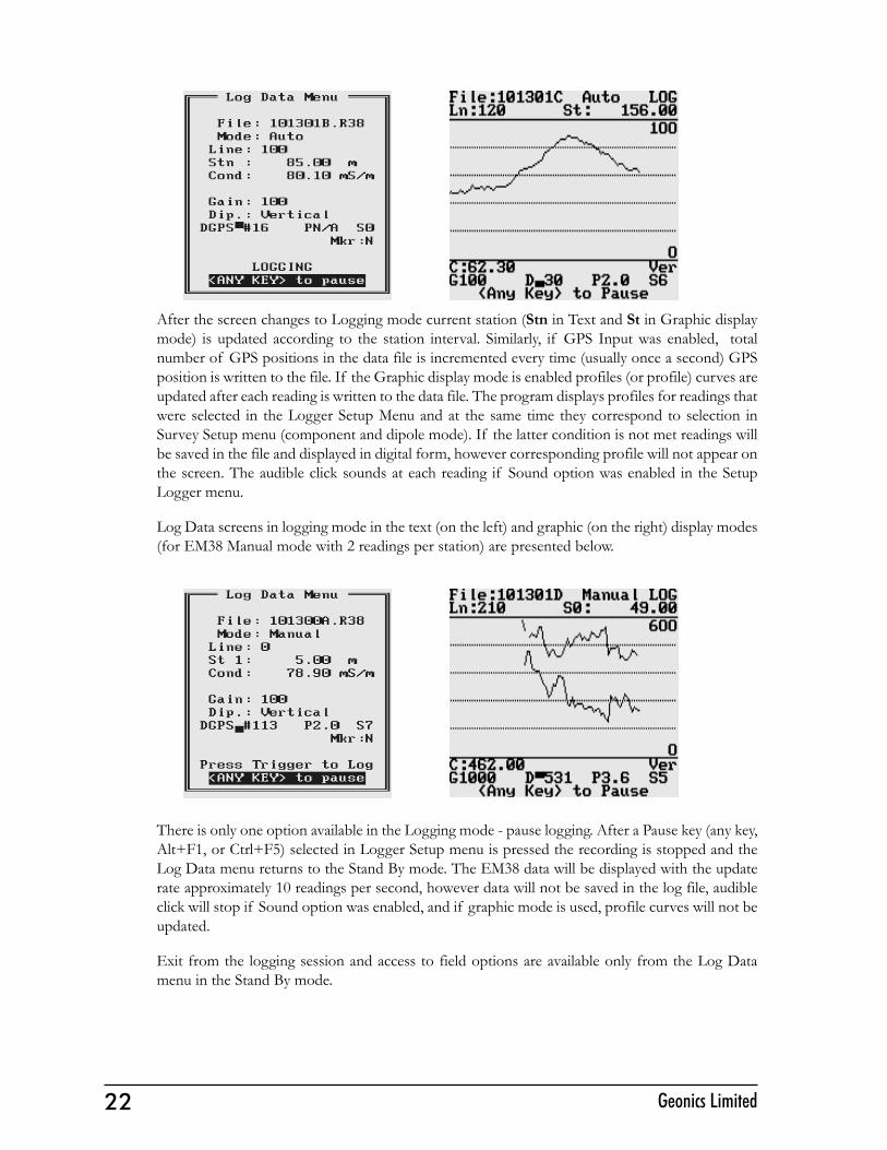
The Logging mode is enabled by pressing the <ENTER> key, which corresponds to label Start inthe Text Display, and GO in the Graphic display mode. After this key is pressed the bottom portionof the screen will change and data will be logged in the mode corresponding to the selected EM38mode in the Survey Setup menu. Log Data screens in logging mode in the text (on the left) andgraphic (on the right) display modes (for EM38 Auto mode) are presented below.
22 Geonics Limited
After the screen changes to Logging mode current station (Stn in Text and St in Graphic displaymode) is updated according to the station interval. Similarly, if GPS Input was enabled, totalnumber of GPS positions in the data file is incremented every time (usually once a second) GPSposition is written to the file. If the Graphic display mode is enabled profiles (or profile) curves areupdated after each reading is written to the data file. The program displays profiles for readings thatwere selected in the Logger Setup Menu and at the same time they correspond to selection inSurvey Setup menu (component and dipole mode). If the latter condition is not met readings willbe saved in the file and displayed in digital form, however corresponding profile will not appear onthe screen. The audible click sounds at each reading if Sound option was enabled in the SetupLogger menu.
Log Data screens in logging mode in the text (on the left) and graphic (on the right) display modes(for EM38 Manual mode with 2 readings per station) are presented below.
There is only one option available in the Logging mode - pause logging. After a Pause key (any key,Alt+F1, or Ctrl+F5) selected in Logger Setup menu is pressed the recording is stopped and theLog Data menu returns to the Stand By mode. The EM38 data will be displayed with the updaterate approximately 10 readings per second, however data will not be saved in the log file, audibleclick will stop if Sound option was enabled, and if graphic mode is used, profile curves will not beupdated.
Exit from the logging session and access to field options are available only from the Log Datamenu in the Stand By mode.
23EM38pro Data Logging System (DL4000/38)
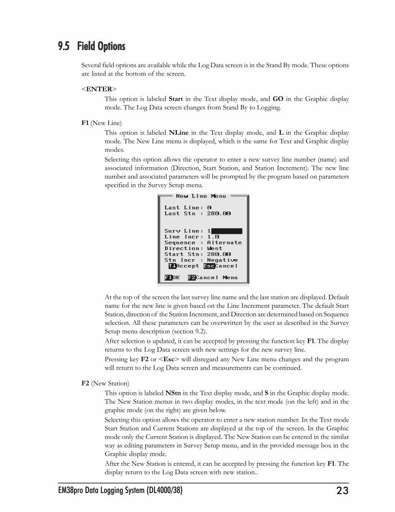
9.5 Field Options9.5 Field Options9.5 Field Options9.5 Field Options9.5 Field OptionsSeveral field options are available while the Log Data screen is in the Stand By mode. These optionsare listed at the bottom of the screen.
<ENTER>This option is labeled Start in the Text display mode, and GO in the Graphic displaymode. The Log Data screen changes from Stand By to Logging.
F1 (New Line)This option is labeled NLine in the Text display mode, and L in the Graphic displaymode. The New Line menu is displayed, which is the same for Text and Graphic displaymodes.Selecting this option allows the operator to enter a new survey line number (name) andassociated information (Direction, Start Station, and Station Increment). The new linenumber and associated parameters will be prompted by the program based on parametersspecified in the Survey Setup menu.
At the top of the screen the last survey line name and the last station are displayed. Defaultname for the new line is given based on the Line Increment parameter. The default StartStation, direction of the Station Increment, and Direction are determined based on Sequenceselection. All these parameters can be overwritten by the user as described in the SurveySetup menu description (section 9.2).After selection is updated, it can be accepted by pressing the function key F1. The displayreturns to the Log Data screen with new settings for the new survey line.Pressing key F2 or <Esc> will disregard any New Line menu changes and the programwill return to the Log Data screen and measurements can be continued.
F2 (New Station)This option is labeled NStn in the Text display mode, and S in the Graphic display mode.The New Station menus in two display modes, in the text mode (on the left) and in thegraphic mode (on the right) are given below.Selecting this option allows the operator to enter a new station number. In the Text modeStart Station and Current Stations are displayed at the top of the screen. In the Graphicmode only the Current Station is displayed. The New Station can be entered in the similarway as editing parameters in Survey Setup menu, and in the provided message box in theGraphic display mode.After the New Station is entered, it can be accepted by pressing the function key F1. Thedisplay return to the Log Data screen with new station..
24 Geonics Limited
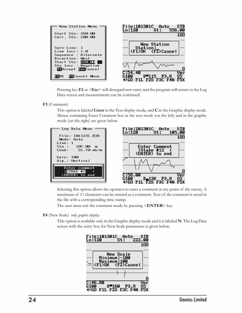
Pressing key F2 or <Esc> will disregard new entry and the program will return to the LogData screen and measurements can be continued.
F3 (Comment)This option is labeled Cmnt in the Text display mode, and C in the Graphic display mode.Menus containing Enter Comment box in the text mode (on the left) and in the graphicmode (on the right) are given below.
Selecting this option allows the operator to enter a comment at any point of the survey. Amaximum of 11 characters can be entered as a comment. Text of the comment is saved inthe file with a corresponding time stamp.The user must exit the comment mode by pressing <ENTER> key.
F4 (New Scale) only graphic displayThis option is available only in the Graphic display mode and it is labeled N. The Log Datascreen with the entry box for New Scale parameters is given below.

25EM38pro Data Logging System (DL4000/38)
Selecting this option allows the operator to enter new scale parameters for the amplitudedisplay. After minimum and maximum values are specified, the function key F1 (OK) willaccept new values and the display will be redrawn (see below). When the key F2 (Cancel) ispressed the new entry is cancelled.
<Del>(delete reading)This option is labeled Rdg in both display modes. The Delete Reading box that appearson the screen, in the text mode (on the left) and in the graphic mode (on the right) isshown below.
This function allows operator to delete previously recorded reading(s). The reading (station)to be deleted is displayed on the screen. The data will only be deleted when the key D ispressed. The program will then display the next previous station, and allow it to be deletedin a similar fashion. If there is no further data available, the program will provide relatedinformation.To exit delete reading mode press key E.
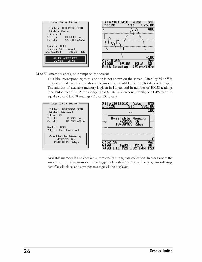
F5 (exit LOG DATA mode)This option is labeled Exit in the text display mode, and X in the graphic display mode.After key F5 is pressed a confirmation prompt Exit Logging Y(es)/N(o) will appear onthe screen as shown below.When the key Y is pressed the data file is closed and the program returns to the AcquiringData menu. In order to continue survey a new data file must be created.If the key N is pressed the program returns to current logging mode.
26 Geonics Limited
M or V (memory check, no prompt on the screen)This label corresponding to this option is not shown on the screen. After key M or V ispressed a small window that shows the amount of available memory for data is displayed.The amount of available memory is given in Kbytes and in number of EM38 readings(one EM38 record is 22 bytes long). If GPS data is taken concurrently, one GPS record isequal to 5 or 6 EM38 readings (110 or 132 bytes).
Available memory is also checked automatically during data collection. In cases where theamount of available memory in the logger is less than 10 Kbytes, the program will stop,data file will close, and a proper message will be displayed.
27EM38pro Data Logging System (DL4000/38)
10. Data T10. Data T10. Data T10. Data T10. Data Transfer (Upload Files)ransfer (Upload Files)ransfer (Upload Files)ransfer (Upload Files)ransfer (Upload Files)
This chapter describes the transfer of data files from a field computer Pro4000 to PC computerusing Download EM38pro Files option of the DAT38W program. Data files can be downloadedby alternative utilities (e.g. ProShell, Lynx, or FileScout in Allegro Field PC) and then these files canbe converted to DAT38 format using option Convert|EM38pro Files in the DAT38W menu.
10.1 Data File Formats10.1 Data File Formats10.1 Data File Formats10.1 Data File Formats10.1 Data File FormatsData files in the field computer are formatted in proprietary EM38pro format. The EM38pro datais saved in one data file with the extension name R38.
Files in the logger format are converted to the DAT38 format during the downloading of data.These new files have same base name with an added extension name G38. Files in the DAT38format can be loaded and processed by the DAT38W program.
While only the DAT38 format is used in data processing, it is strongly advised that data in the raw(EM38pro) format be saved as well. In the case of any hardware malfunction, i.e. a damagedinstrument cable, only the file in logger format may indicate the source of the problem. Additionally,raw data files also contain useful information about the instrument settings used during field work.Files in the EM38pro format can be converted to the DAT38 format at any time using the ConvertEM38pro Files option of the DAT38W menu.
Description and sample of the EM38 files in the EM38pro format, as well as an example of a fileconverted to the DAT38 format are placed in Appendix A of DAT38W manual.
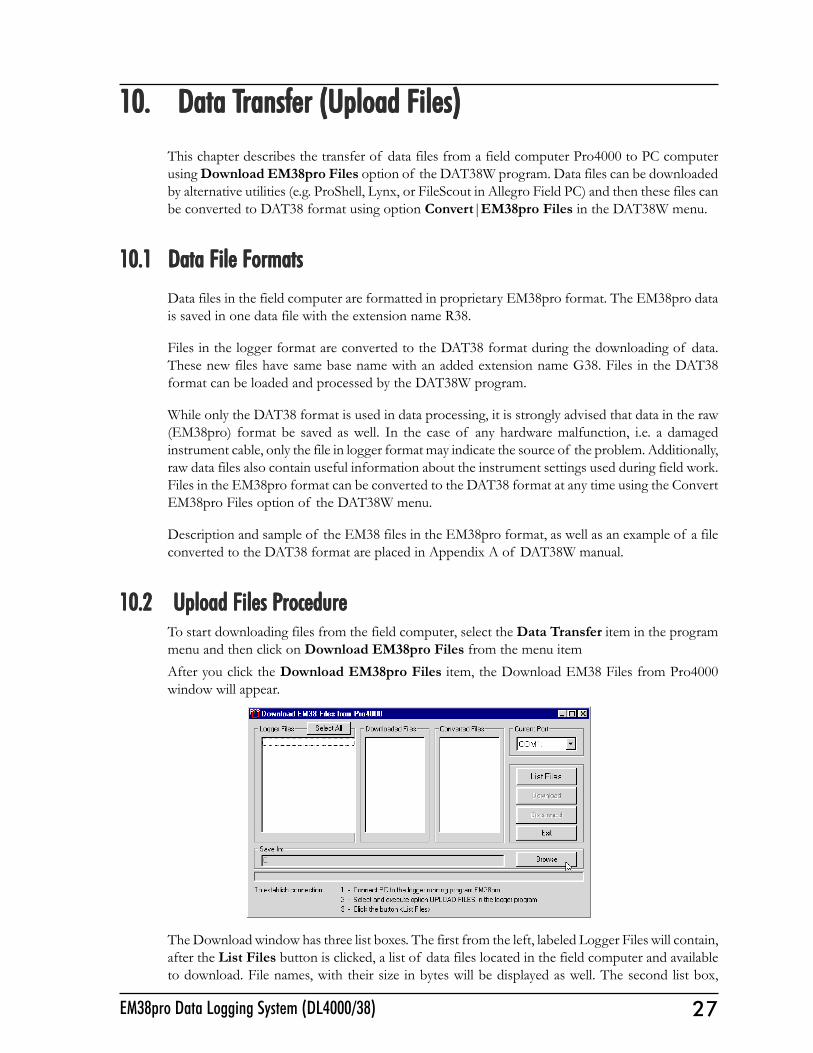
10.2 Upload Files P10.2 Upload Files P10.2 Upload Files P10.2 Upload Files P10.2 Upload Files ProcedurerocedurerocedurerocedurerocedureTo start downloading files from the field computer, select the Data Transfer item in the programmenu and then click on Download EM38pro Files from the menu itemAfter you click the Download EM38pro Files item, the Download EM38 Files from Pro4000window will appear.
The Download window has three list boxes. The first from the left, labeled Logger Files will contain,after the List Files button is clicked, a list of data files located in the field computer and availableto download. File names, with their size in bytes will be displayed as well. The second list box,
28 Geonics Limited
labeled Downloaded Files, will list downloaded data files in the EM38pro format, and the third,Converted Files, will list files converted to DAT38 format. If a file name already exists on thecomputer hard disk, an underscore followed by a letter will be added to the base name. (ie. file nameABC.R38 would be changed to ABC_1.R38, ABC_2.R38, and so on.)
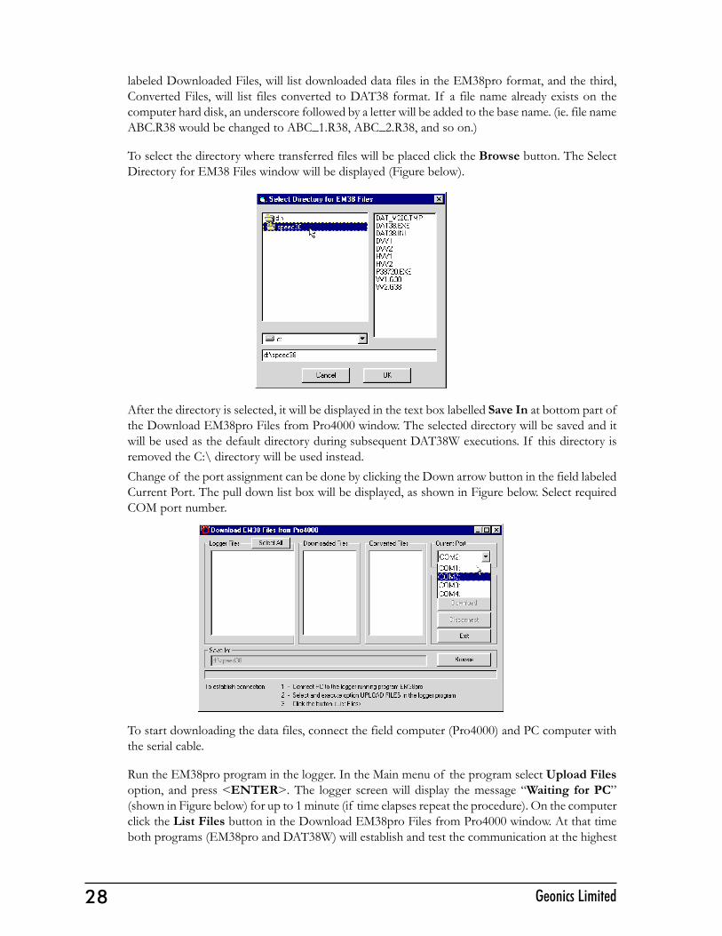
To select the directory where transferred files will be placed click the Browse button. The SelectDirectory for EM38 Files window will be displayed (Figure below).
After the directory is selected, it will be displayed in the text box labelled Save In at bottom part ofthe Download EM38pro Files from Pro4000 window. The selected directory will be saved and itwill be used as the default directory during subsequent DAT38W executions. If this directory isremoved the C:\ directory will be used instead.Change of the port assignment can be done by clicking the Down arrow button in the field labeledCurrent Port. The pull down list box will be displayed, as shown in Figure below. Select requiredCOM port number.
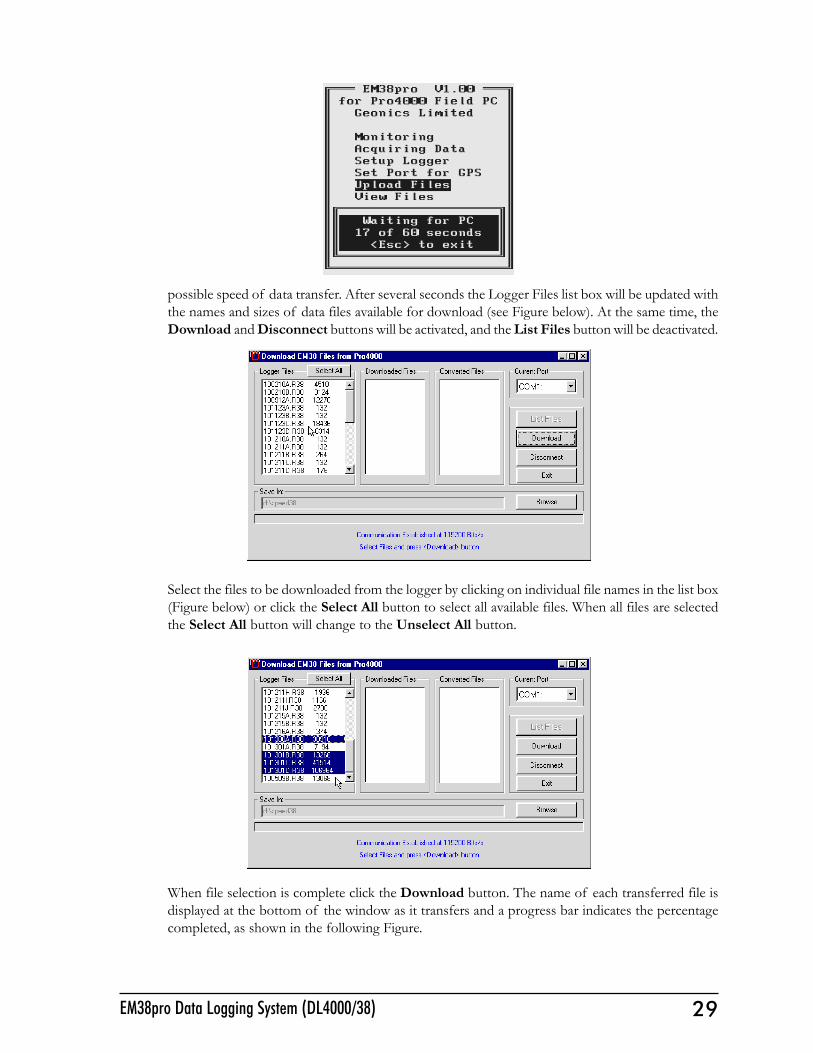
To start downloading the data files, connect the field computer (Pro4000) and PC computer withthe serial cable.
Run the EM38pro program in the logger. In the Main menu of the program select Upload Filesoption, and press <ENTER>. The logger screen will display the message �Waiting for PC�(shown in Figure below) for up to 1 minute (if time elapses repeat the procedure). On the computerclick the List Files button in the Download EM38pro Files from Pro4000 window. At that timeboth programs (EM38pro and DAT38W) will establish and test the communication at the highest
29EM38pro Data Logging System (DL4000/38)
possible speed of data transfer. After several seconds the Logger Files list box will be updated withthe names and sizes of data files available for download (see Figure below). At the same time, theDownload and Disconnect buttons will be activated, and the List Files button will be deactivated.
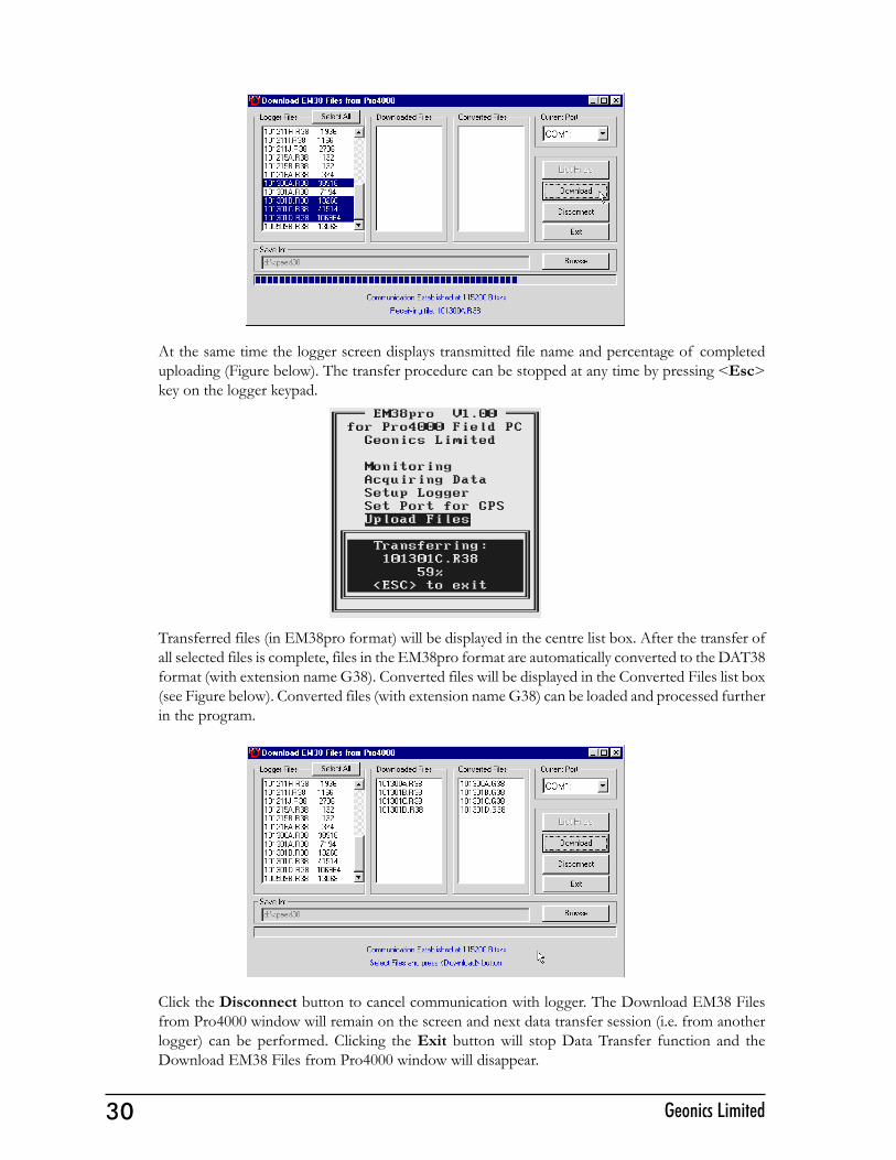
Select the files to be downloaded from the logger by clicking on individual file names in the list box(Figure below) or click the Select All button to select all available files. When all files are selectedthe Select All button will change to the Unselect All button.
When file selection is complete click the Download button. The name of each transferred file isdisplayed at the bottom of the window as it transfers and a progress bar indicates the percentagecompleted, as shown in the following Figure.
30 Geonics Limited
At the same time the logger screen displays transmitted file name and percentage of completeduploading (Figure below). The transfer procedure can be stopped at any time by pressing <Esc>key on the logger keypad.
Transferred files (in EM38pro format) will be displayed in the centre list box. After the transfer ofall selected files is complete, files in the EM38pro format are automatically converted to the DAT38format (with extension name G38). Converted files will be displayed in the Converted Files list box(see Figure below). Converted files (with extension name G38) can be loaded and processed furtherin the program.
Click the Disconnect button to cancel communication with logger. The Download EM38 Filesfrom Pro4000 window will remain on the screen and next data transfer session (i.e. from anotherlogger) can be performed. Clicking the Exit button will stop Data Transfer function and theDownload EM38 Files from Pro4000 window will disappear.
31EM38pro Data Logging System (DL4000/38)
11. View Files11. View Files11. View Files11. View Files11. View Files
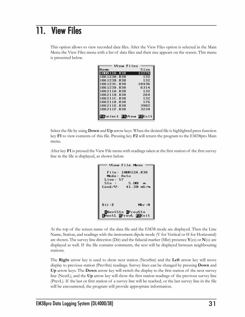
This option allows to view recorded data files. After the View Files option is selected in the MainMenu the View Files menu with a list of data files and their size appears on the screen. This menuis presented below.
Select the file by using Down and Up arrow keys. When the desired file is highlighted press functionkey F1 to view contents of this file. Pressing key F2 will return the program to the EM38pro Mainmenu.
After key F1 is pressed the View File menu with readings taken at the first station of the first surveyline in the file is displayed, as shown below.
At the top of the screen name of the data file and the EM38 mode are displayed. Then the LineName, Station, and readings with the instrument dipole mode (V for Vertical or H for Horizontal)are shown. The survey line direction (Dir) and the fiducial marker (Mkr) presence Y(es) or N(o) aredisplayed as well. If the file contains comments, the text will be displayed between neighbouringstations.
The Right arrow key is used to show next station (NextStn) and the Left arrow key will movedisplay to previous station (PrevStn) readings. Survey lines can be changed by pressing Down andUp arrow keys. The Down arrow key will switch the display to the first station of the next surveyline (NextL), and the Up arrow key will show the first station readings of the previous survey line(PrevL). If the last or first station of a survey line will be reached, or the last survey line in the filewill be encountered, the program will provide appropriate information.
32 Geonics Limited
12. Delete Files12. Delete Files12. Delete Files12. Delete Files12. Delete Files
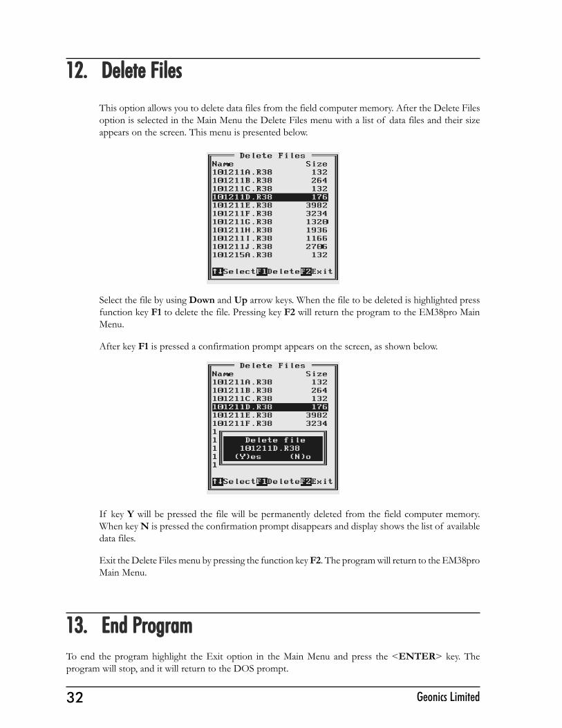
This option allows you to delete data files from the field computer memory. After the Delete Filesoption is selected in the Main Menu the Delete Files menu with a list of data files and their sizeappears on the screen. This menu is presented below.
Select the file by using Down and Up arrow keys. When the file to be deleted is highlighted pressfunction key F1 to delete the file. Pressing key F2 will return the program to the EM38pro MainMenu.
After key F1 is pressed a confirmation prompt appears on the screen, as shown below.
If key Y will be pressed the file will be permanently deleted from the field computer memory.When key N is pressed the confirmation prompt disappears and display shows the list of availabledata files.
Exit the Delete Files menu by pressing the function key F2. The program will return to the EM38proMain Menu.
13. End P13. End P13. End P13. End P13. End ProgramrogramrogramrogramrogramTo end the program highlight the Exit option in the Main Menu and press the <ENTER> key. Theprogram will stop, and it will return to the DOS prompt.
33EM38pro Data Logging System (DL4000/38)
Appendix AAppendix AAppendix AAppendix AAppendix A
AAAAA.1 Using the EM38pro with a GPS System.1 Using the EM38pro with a GPS System.1 Using the EM38pro with a GPS System.1 Using the EM38pro with a GPS System.1 Using the EM38pro with a GPS SystemThe EM38pro program accepts input from GPS systems that stream NMEA-0183 compatibledata. through their output port. The program uses two NMEA messages: GGA and GSA. Theentire GGA message is written to the EM38pro data file, while the GSA message is used only todisplay PDOP index on the logger screen.
The GPS system means (control device, receiver panel, or manufacturer software) must be used toset GPS receiver communication parameters, to specify frequency of GPS output, and number andtype of NMEA messages sent by the GPS system output port. Any GPS system can send variousNMEA messages. It is important to select only two messages (GGA and GSA) that are actuallyused by EM38pro. The program will accept any GPS string sent by the GPS receiver, however ituses time to process GPS data that is not being used. Therefore, selecting a larger number ofNMEA messages for GPS output will result in slower data acquisition of EM38pro. Normally, theEM38pro running in Pro4000 logger uses less than 100 ms to process and record GPS data fromtwo NMEA messages, GGA and GSA.
Only message GGA is necessary to position EM38 data. If message GSA is not available in aparticular system, the EM38pro will function and record position data based on GGA message.Lack of GSA message will result in PDOP index displayed as Not Available (N/A) on the loggerdisplay.
The EM38pro dedicates one line of the display to show GPS status. A label DGPS (DifferentialGlobal Positioning System) in text mode or D in graphic mode indicates that GPS readings aredifferentially corrected in real time Label AGPS (Autonomous Global Positioning System) or A ingraphic mode indicates lack of differential correction. On the right side of DGPS or AGPS (D orA in graphic mode) a label small square is displayed. This square should move down and up withthe frequency of GPS update rate (usually 1 second intervals). If the square is not moving forlonger period of time it means that GPS system is not working or that it is not connected to thefield computer. Number of recorded GPS positions are displayed on the right side of the smallsquare. This number is updated only in the logging mode, when the data are recorded. (In Stand Bymode or during Monitoring only the moving square, and updated values of PDOP and number oftracked satellites, indicate presence of GPS input).
Two more GPS parameters are displayed on the logger screen. These are index PDOP shown bylabel P and number of tracked satellites represented by label S. The index called PDOP (PositionDilution of Precision) measures the strength of satellite coverage for a given area. PDOP is affectedby the number of satellites visible and their relative positions in the sky. The smaller the number ofPDOP the stronger the satellite coverage is. When there are more than 5 satellites widely spacedvisible, the PDOP is 4 or less. However, when there are less satellites visible, or they are unevenlyspaced in the sky, PDOP values can be 6 or higher. In most cases, the PDOP in an open sky is lessthan 3, and most accuracies given for many GPS systems are given for this norm. Refer to GPSdocumentation and literature for more information related to error sources of GPS positioning.
34 Geonics Limited
AAAAA.2 Description of GGA and GSA Data Messages.2 Description of GGA and GSA Data Messages.2 Description of GGA and GSA Data Messages.2 Description of GGA and GSA Data Messages.2 Description of GGA and GSA Data Messages
GGA Data MessageGGA Data MessageGGA Data MessageGGA Data MessageGGA Data Message
The GGA message contains the GPS position information and it is the most widely used NMEAdata message. This message takes the following form:
$GPGGA,hhmmss.ss,ddmm.mmmmm,s,dddmm.mmmmm,s,n,qq,pp.p,saaaaa.aa,u,+xxxx.x,M,sss,aaaa*cc<CR><LF>
Definition of GGA message component:
hhmmss.ss UTC time in hours, minutes, seconds of the GPS positionddmm.mmmmm Latitude in degrees, minutes, and decimal minutess s=N or s=S, for North and South latitudedddmm.mmmmm Longitude in degrees, minutes, and decimal minutess s=E or s=W, for East and West longituden Quality indicator, 0 = no position, 1 = raw, no differentially corrected
position, 2 = differentially corrected position, 9 = position computedusing almanac information
qq Number of satellites used in position computationpp.p HDOP = 0.0 to 99.9saaaaa.aa Antenna altitudeu Altitude units, M=meters+xxxx.x Geoidal separation (requires geoidal height option)M Geoidal separation units, M = meterssss Age of differential corrections in secondsaaaa Base station identification*cc Checksum<CR><LF> Carriage return and Line feed
GSA Data MessageGSA Data MessageGSA Data MessageGSA Data MessageGSA Data Message
The GSA message contains active satellites and PDOP value. The GSA message is given in thefollowing form:
$GPGSA,c1,d1,d2,d3,d4,d5,d6,d7,d8,d9,d10,d11,d12,d13,f1,f2,f3*cc<CR><LF>
Definition of GSA message components:
c1 Mode, M = manual, A = automaticd1 Mode, 2 = 2D, 3 = 3Dd2-d13 Satellites used in position computation (range 0 to 32)f1 PDOP (range 0 to 99.9)f2 HDOP (range 0 to 99.9)f3 VDOP (range 0 to 99.9)*cc Checksum<CR><LF> Carriage return and Line Feed
35EM38pro Data Logging System (DL4000/38)
Appendix BAppendix BAppendix BAppendix BAppendix B
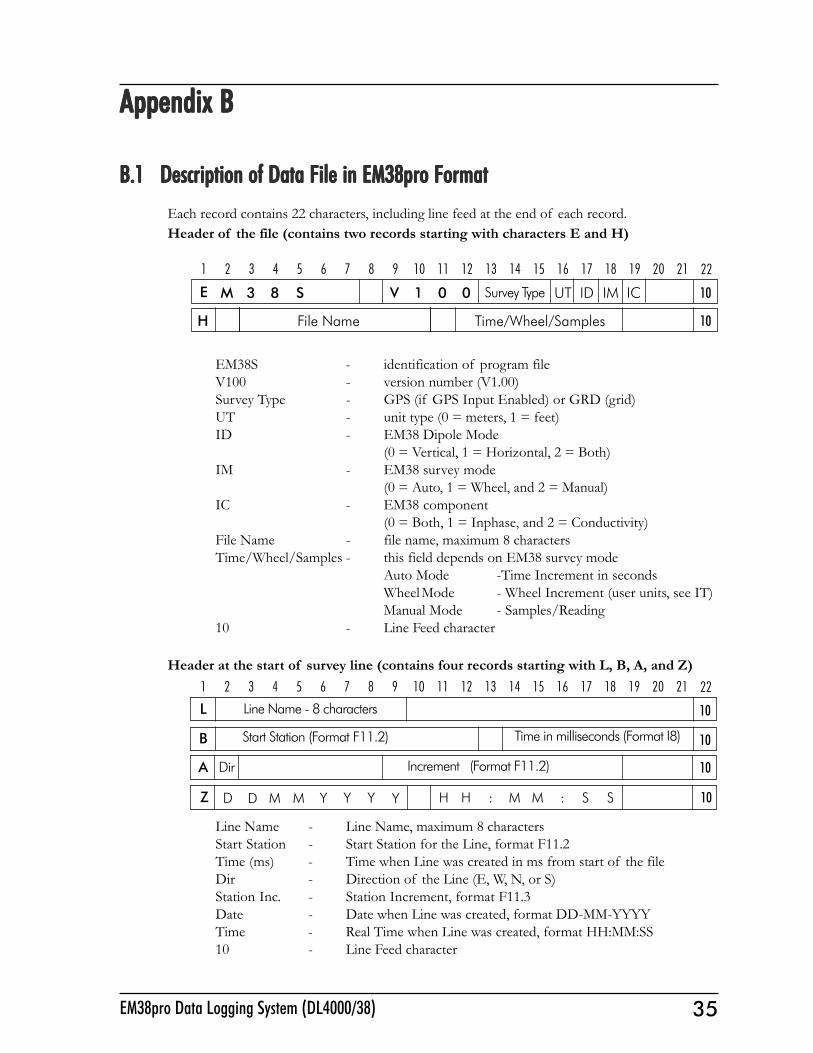
B.1 Description of Data File in EM38pro FormatB.1 Description of Data File in EM38pro FormatB.1 Description of Data File in EM38pro FormatB.1 Description of Data File in EM38pro FormatB.1 Description of Data File in EM38pro FormatEach record contains 22 characters, including line feed at the end of each record.Header of the file (contains two records starting with characters E and H)
EM38S - identification of program fileV100 - version number (V1.00)Survey Type - GPS (if GPS Input Enabled) or GRD (grid)UT - unit type (0 = meters, 1 = feet)ID - EM38 Dipole Mode
(0 = Vertical, 1 = Horizontal, 2 = Both)IM - EM38 survey mode
(0 = Auto, 1 = Wheel, and 2 = Manual)IC - EM38 component
(0 = Both, 1 = Inphase, and 2 = Conductivity)File Name - file name, maximum 8 charactersTime/Wheel/Samples - this field depends on EM38 survey mode
Auto Mode -Time Increment in secondsWheelMode - Wheel Increment (user units, see IT)Manual Mode - Samples/Reading
10 - Line Feed character
Header at the start of survey line (contains four records starting with L, B, A, and Z)
Line Name - Line Name, maximum 8 charactersStart Station - Start Station for the Line, format F11.2Time (ms) - Time when Line was created in ms from start of the fileDir - Direction of the Line (E, W, N, or S)Station Inc. - Station Increment, format F11.3Date - Date when Line was created, format DD-MM-YYYYTime - Real Time when Line was created, format HH:MM:SS10 - Line Feed character
1 2 3 4 5 6 7 8 9 10 11 12 13 14 15 16 17 18 19 20 21
10
22
L Line Name - 8 characters
A
10B Start Station (Format F11.2)
Dir Increment (Format F11.2)
Z D YYYMM Y H H : M M : S SD
10
10
Time in milliseconds (Format I8)
1 2 3 4 5 6 7 8 9 10 11 12 13 14 15 16 17 18 19 20 21
M 3 8 V 1 0 UT0 ID IM 10
22
E Survey Type
H File Name Time/Wheel/Samples 10
ICS
36 Geonics Limited
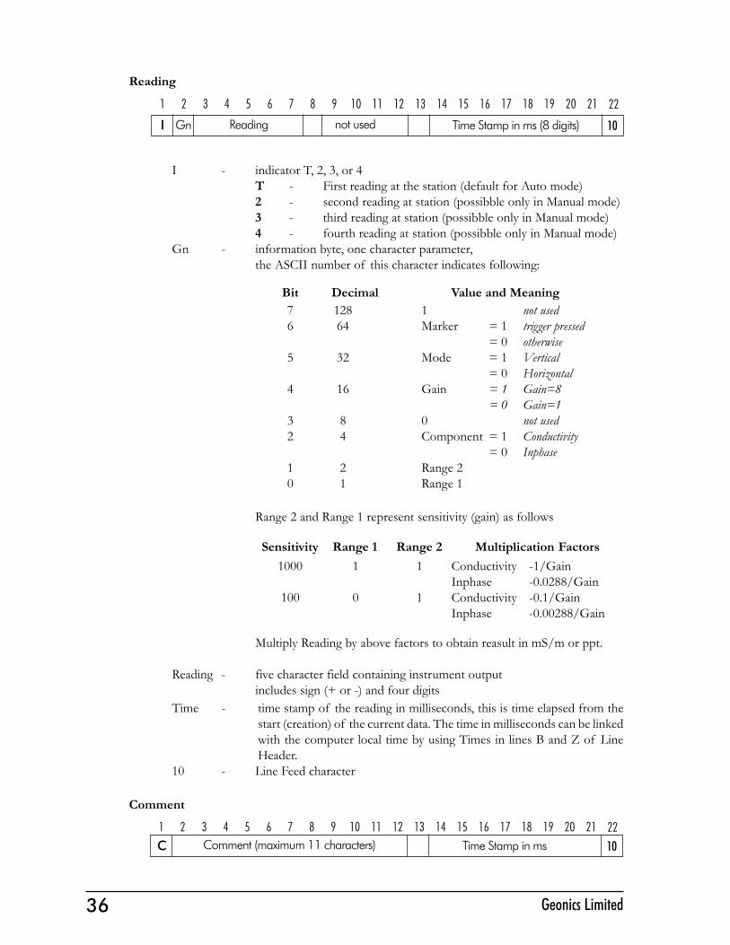
Reading
I - indicator T, 2, 3, or 4T - First reading at the station (default for Auto mode)2 - second reading at station (possibble only in Manual mode)3 - third reading at station (possibble only in Manual mode)4 - fourth reading at station (possibble only in Manual mode)
Gn - information byte, one character parameter,the ASCII number of this character indicates following:
Range 2 and Range 1 represent sensitivity (gain) as follows
Multiply Reading by above factors to obtain reasult in mS/m or ppt.
Reading - five character field containing instrument outputincludes sign (+ or -) and four digits
Time - time stamp of the reading in milliseconds, this is time elapsed from thestart (creation) of the current data. The time in milliseconds can be linkedwith the computer local time by using Times in lines B and Z of LineHeader.
10 - Line Feed character
Comment
C Comment (maximum 11 characters) 10Time Stamp in ms1 2 3 4 5 6 7 8 9 10 11 12 13 14 15 16 17 18 19 20 21 22
Bit Decimal Value and Meaning76
5
4
32
10
12864
32
16
84
21
1 not usedMarker = 1 trigger pressed
= 0 otherwiseMode = 1 Vertical
= 0 HorizontalGain = 1 Gain=8
= 0 Gain=10 not usedComponent = 1 Conductivity
= 0 InphaseRange 2Range 1
I Gn not used Time Stamp in ms (8 digits) 10Reading
1 2 3 4 5 6 7 8 9 10 11 12 13 14 15 16 17 18 19 20 21 22
Sensitivity Range 1 Range 21000
100
1
0
1
1
Multiplication FactorsConductivity -1/GainInphase -0.0288/GainConductivity -0.1/GainInphase -0.00288/Gain
37EM38pro Data Logging System (DL4000/38)
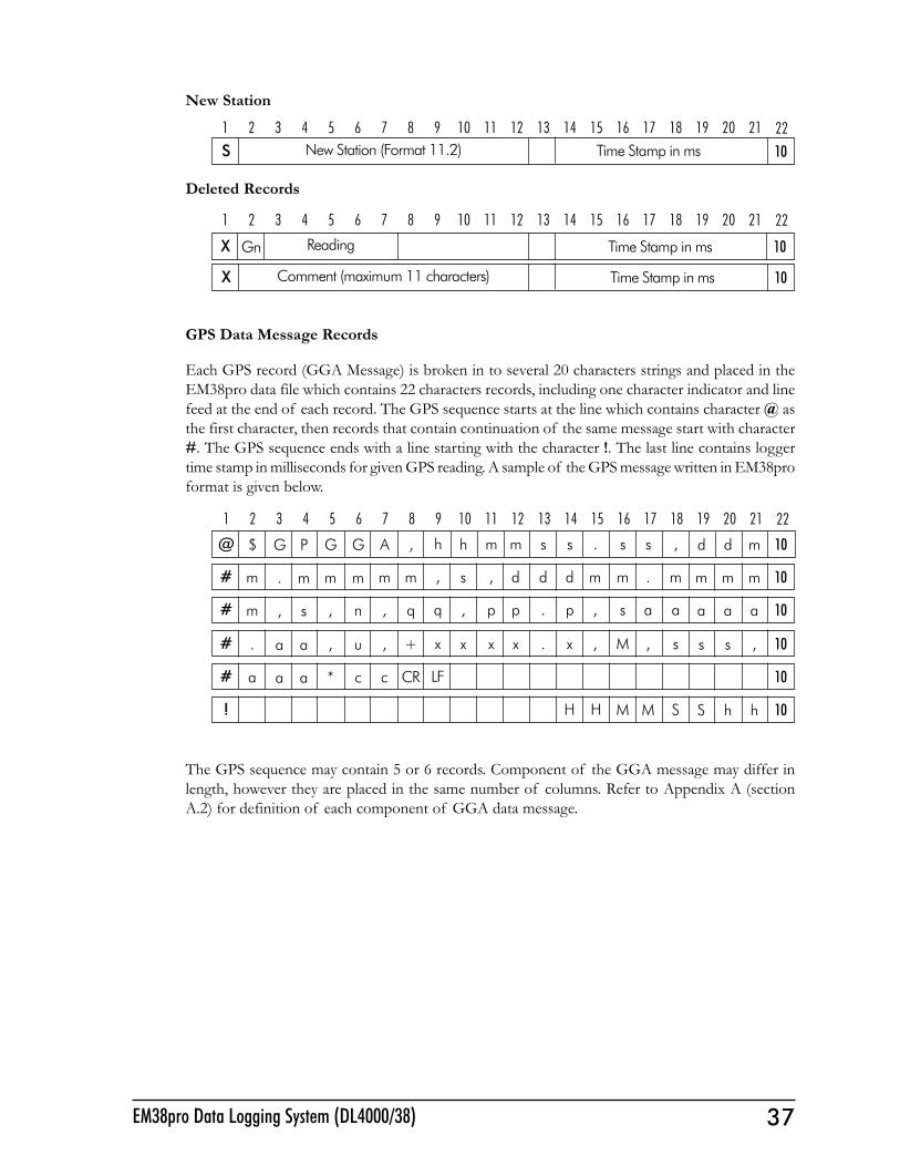
New Station
Deleted Records
GPS Data Message Records
Each GPS record (GGA Message) is broken in to several 20 characters strings and placed in theEM38pro data file which contains 22 characters records, including one character indicator and linefeed at the end of each record. The GPS sequence starts at the line which contains character @ asthe first character, then records that contain continuation of the same message start with character#. The GPS sequence ends with a line starting with the character !. The last line contains loggertime stamp in milliseconds for given GPS reading. A sample of the GPS message written in EM38proformat is given below.
The GPS sequence may contain 5 or 6 records. Component of the GGA message may differ inlength, however they are placed in the same number of columns. Refer to Appendix A (sectionA.2) for definition of each component of GGA data message.
S New Station (Format 11.2) 10Time Stamp in ms1 2 3 4 5 6 7 8 9 10 11 12 13 14 15 16 17 18 19 20 21 22
1 2 3 4 5 6 7 8 9 10 11 12 13 14 15 16 17 18 19 20 21 22
@ $ ,AGG h m m s s . s s ,h d d m 10G P
# m mmmm , , d d d m m . ms m m m 10. m
# m q,n, q p p . p , s a a, a a a 10, s
# . +,u, x x x . x , M , sx s s , 10a a
# a CRcc* LF 10a a
! M M S S h h 10HH
X Gn Reading Time Stamp in ms 10
1 2 3 4 5 6 7 8 9 10 11 12 13 14 15 16 17 18 19 20 21 22
X Comment (maximum 11 characters) 10Time Stamp in ms
38 Geonics Limited
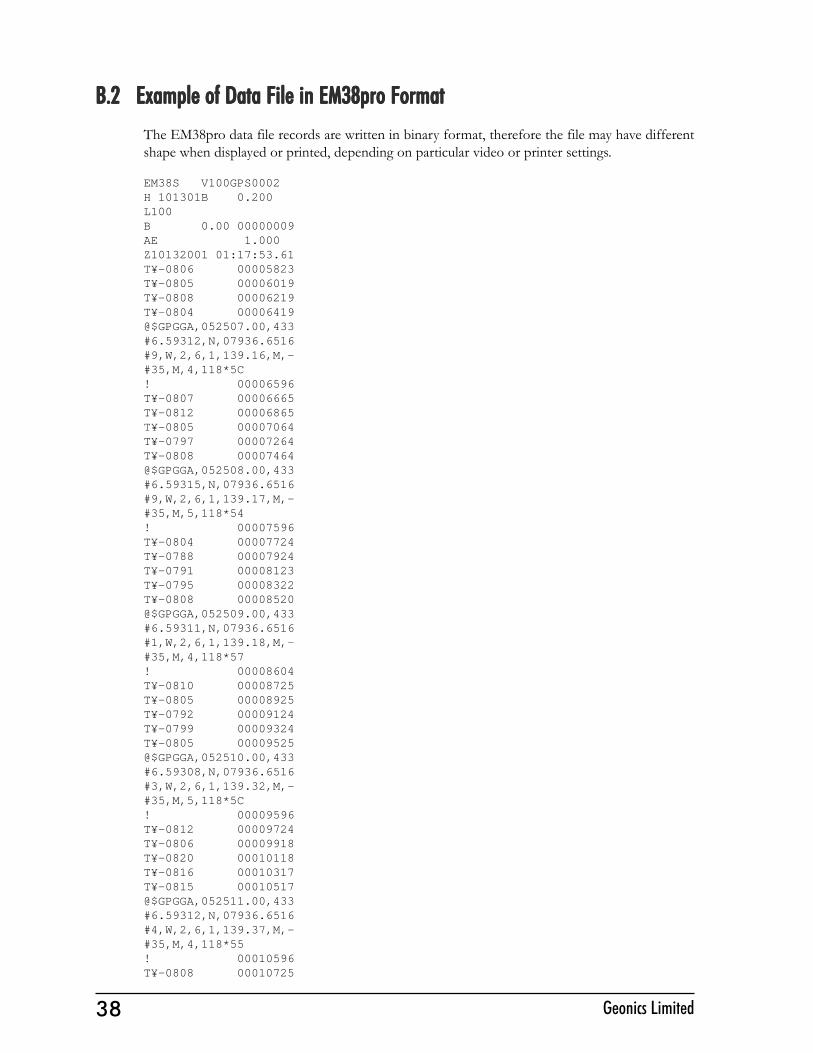
B.2 Example of Data File in EM38pro FormatB.2 Example of Data File in EM38pro FormatB.2 Example of Data File in EM38pro FormatB.2 Example of Data File in EM38pro FormatB.2 Example of Data File in EM38pro FormatThe EM38pro data file records are written in binary format, therefore the file may have differentshape when displayed or printed, depending on particular video or printer settings.
EM38S V100GPS0002H 101301B 0.200L100B 0.00 00000009AE 1.000Z10132001 01:17:53.61T¥-0806 00005823T¥-0805 00006019T¥-0808 00006219T¥-0804 00006419@$GPGGA,052507.00,433#6.59312,N,07936.6516#9,W,2,6,1,139.16,M,-#35,M,4,118*5C! 00006596T¥-0807 00006665T¥-0812 00006865T¥-0805 00007064T¥-0797 00007264T¥-0808 00007464@$GPGGA,052508.00,433#6.59315,N,07936.6516#9,W,2,6,1,139.17,M,-#35,M,5,118*54! 00007596T¥-0804 00007724T¥-0788 00007924T¥-0791 00008123T¥-0795 00008322T¥-0808 00008520@$GPGGA,052509.00,433#6.59311,N,07936.6516#1,W,2,6,1,139.18,M,-#35,M,4,118*57! 00008604T¥-0810 00008725T¥-0805 00008925T¥-0792 00009124T¥-0799 00009324T¥-0805 00009525@$GPGGA,052510.00,433#6.59308,N,07936.6516#3,W,2,6,1,139.32,M,-#35,M,5,118*5C! 00009596T¥-0812 00009724T¥-0806 00009918T¥-0820 00010118T¥-0816 00010317T¥-0815 00010517@$GPGGA,052511.00,433#6.59312,N,07936.6516#4,W,2,6,1,139.37,M,-#35,M,4,118*55! 00010596T¥-0808 00010725
39EM38pro Data Logging System (DL4000/38)
Appendix CAppendix CAppendix CAppendix CAppendix C
C.1 Short Overview of PC.1 Short Overview of PC.1 Short Overview of PC.1 Short Overview of PC.1 Short Overview of Programs Lrograms Lrograms Lrograms Lrograms Lynx and Pynx and Pynx and Pynx and Pynx and ProShellroShellroShellroShellroShellTwo programs, ProShell (includes ProLink) and Lynx, are supplied with the Pro4000 system andcan be used to transfer files between the Pro4000 and a desktop Windows based computer.
The program ProLink is factory installed in the Pro4000 ROM (drive A:). When ProShell is run(type PS to run ProShell in Pro4000) ProLink is automatically initiated.
Lynx runs on computers equipped with Windows 95 or higher. To install Lynx, insert the Pro4000Setup disk (Utility disk #1) into drive A: on your computer and run the Setup program. The Lynxicon will appear on your desktop after installation is complete. When Lynx is started two WindowsExplorer type screens will be displayed. The top screen, labeled Local, displays the contents of thePC. The bottom screen, labeled Remote, displays the contents of the Pro4000 assuming a connectionis established. Several file management functions can be performed using Lynx, including FileTransfer, renaming folders, creating new folders or sub-folders, and deleting files.
C.2 Establishing CommunicationC.2 Establishing CommunicationC.2 Establishing CommunicationC.2 Establishing CommunicationC.2 Establishing CommunicationTo transfer data to and from a base computer, attach the cable (null modem serial communicationcable) between the Pro4000 and the computer COM ports. Run ProShell on the Pro4000 (typecommand PS to run ProShell ) and Lynx on the PC computer.
Correct communication ports must be selected on both computers. To set up the serial port on thePC, from Lynx select the Transfer/Select COM Port menu option. To set up the communicationport on the Pro4000, press <F5>(Xfer) from main screen of ProShell, and then press <F1> totoggle between ports COM1 and COM2.
Juniper Systems recommends that the Pro4000 is in auto baud rate detection mode (the defaultsetting). In this mode, the Pro4000 tries to establish communication at 115K baud, and in casecommunication fails at this rate, it automatically steps down to the next slowest rate untilcommunication is established.
To start communication click on the Connect button (the green circulating arrows in the centretool bar) or select the Transfer/Connect to Remote menu option from Lynx. When connection isestablished the contents of the Pro4000 Field Computer will be displayed in the Lynx bottomRemote view screen.
C.3 TC.3 TC.3 TC.3 TC.3 Transferring Files to the Pransferring Files to the Pransferring Files to the Pransferring Files to the Pransferring Files to the Pro4000 from the PCro4000 from the PCro4000 from the PCro4000 from the PCro4000 from the PCSelect the folder in the Remote view screen. Transferred files will be saved in this folder.In the Local view screen select files to be transferred to the Pro4000.Click the Down arrow button or select Transfer/Send to Remote from the main menu. File transferstarts immediately. In cases where the selected file exists in the logger the program will prompt forpermission to overwrite.
40 Geonics Limited
C.4 TC.4 TC.4 TC.4 TC.4 Transferring Files from the Pransferring Files from the Pransferring Files from the Pransferring Files from the Pransferring Files from the Pro4000 to the PCro4000 to the PCro4000 to the PCro4000 to the PCro4000 to the PCSelect the folder in the Local view screen. Transferred files will be saved in this folder.In the Remote view screen select files to be transferred to the PC.Click the Up arrow button or select Transfer/Receive from Remote from the main menu. Filetransfer starts immediately. If selected files exist in the selected folder in the PC the program willprompt for permission to overwrite.
When the transferring session is finished click the Disconnect button before disconnecting the serial cable.Otherwise, the Esc key must be pressed on the logger to return the Pro4000 to normal function.Please refer to Pro4000 Field Computer User�s Manual (Section 5) for more detailed description of ProShelland Lynx functions.