Embed Size (px)
Citation preview
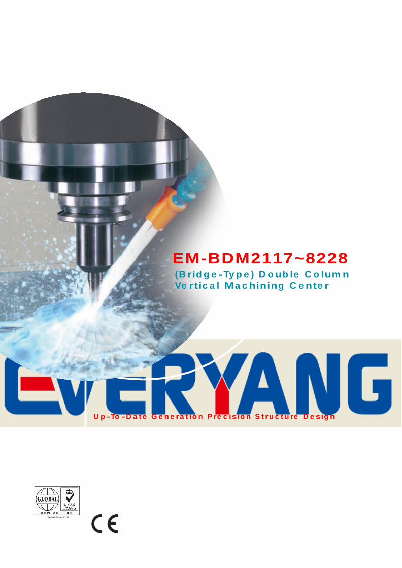
EM-BDM2117~8228 ( B r i d g e - Ty p e ) D o u b l e C o l u m n
Ve r t i c a l M a c h i n i n g C e n t e r
U p - To - D a t e G e n e r a t i o n P re c i s i o n S t r u c t u re D e s i g n
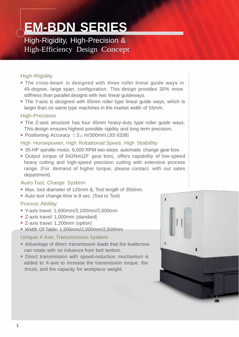
EM-BDN SERIES High-Rigidity, High-Precision &
High-Efficiency Design Concept
High-Rigidity ● The cross-beam is designed with three roller linear guide ways in
45-degree, large span, configuration. This design provides 35% more
stiffness than parallel designs with two linear guideways. ● The Y-axis is designed with 65mm roller type linear guide ways, which is
larger than on same type machines in the market width of 55mm.
High-Precision ● The Z-axis structure has four 45mm heavy-duty type roller guide ways.
This design ensures highest possible rigidity and long term precision. ● Positioning Accuracy ±3μm/300mm.(JIS 6338)
High Horsepower, High Rotational Speed, High Stability ● 35-HP spindle motor, 6,000 RPM two-steps automatic change gear box. ● Output torque of 642Nm(ZF gear box), offers capability of low-speed
heavy cutting and high-speed precision cutting with extensive process
range. (For demand of higher torque, please contact with our sales
department).
Auto TooL Change System ● Max. tool diameter of 125mm &, Tool length of 350mm. ● Auto tool change time is 8 sec. (Tool to Tool)
Process Ability ● Y-axis travel: 1,600mm/2,100mm/2,600mm ● Z-axis travel: 1,000mm (standard) ● Z-axis travel: 1,200mm (option) ● Width Of Table: 1,500mm/2,000mm/2,500mm
Unique X Axis Transmission System ● Advantage of direct transmission leads that the leadscrew
can rotate with no influence from belt tention. ● Direct transmission with speed-reduction mechanism is
added to X-axis to increase the transmission torque, the
thrust, and the capacity for workpiece weight.
1
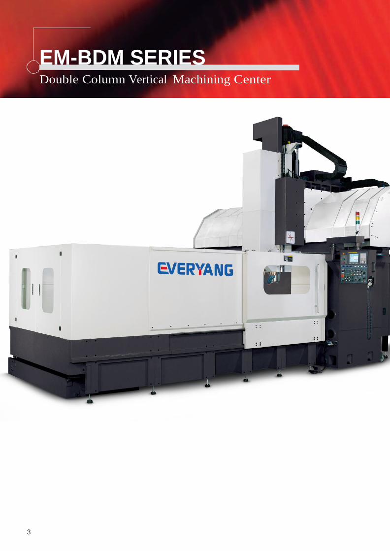
EM-BDM SERIES Double Column Vertical Machining Center
3
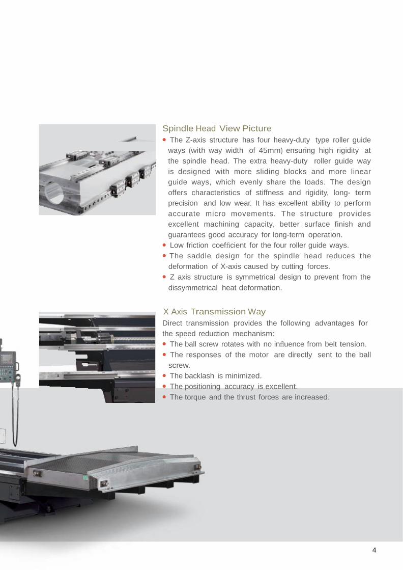
Spindle Head View Picture ● The Z-axis structure has four heavy-duty type roller guide
ways (with way width of 45mm) ensuring high rigidity at
the spindle head. The extra heavy-duty roller guide way
is designed with more sliding blocks and more linear
guide ways, which evenly share the loads. The design
offers characteristics of stiffness and rigidity, long- term
precision and low wear. It has excellent ability to perform
accurate micro movements. The structure provides
excellent machining capacity, better surface finish and
guarantees good accuracy for long-term operation.
● Low friction coefficient for the four roller guide ways.
● The saddle design for the spindle head reduces the
deformation of X-axis caused by cutting forces.
● Z axis structure is symmetrical design to prevent from the
dissymmetrical heat deformation.
X Axis Transmission Way
Direct transmission provides the following advantages for
the speed reduction mechanism:
● The ball screw rotates with no influence from belt tension.
● The responses of the motor are directly sent to the ball
screw.
● The backlash is minimized.
● The positioning accuracy is excellent.
● The torque and the thrust forces are increased.
4
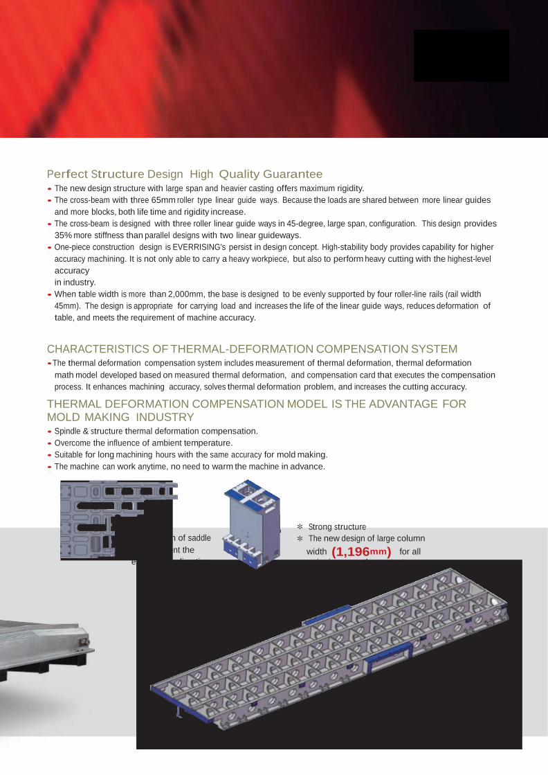
Perfect Structure Design High Quality Guarantee ● The new design structure with large span and heavier casting offers maximum rigidity.
● The cross-beam with three 65mm roller type linear guide ways. Because the loads are shared between more linear guides
and more blocks, both life time and rigidity increase.
● The cross-beam is designed with three roller linear guide ways in 45-degree, large span, configuration. This design provides
35% more stiffness than parallel designs with two linear guideways.
● One-piece construction design is EVERRISING's persist in design concept. High-stability body provides capability for higher
accuracy machining. It is not only able to carry a heavy workpiece, but also to perform heavy cutting with the highest-level
accuracy
in industry.
● When table width is more than 2,000mm, the base is designed to be evenly supported by four roller-line rails (rail width
45mm). The design is appropriate for carrying load and increases the life of the linear guide ways, reduces deformation of
table, and meets the requirement of machine accuracy.
CHARACTERISTICS OF THERMAL-DEFORMATION COMPENSATION SYSTEM ● The thermal deformation compensation system includes measurement of thermal deformation, thermal deformation
math model developed based on measured thermal deformation, and compensation card that executes the compensation
process. It enhances machining accuracy, solves thermal deformation problem, and increases the cutting accuracy.
THERMAL DEFORMATION COMPENSATION MODEL IS THE ADVANTAGE FOR MOLD MAKING INDUSTRY ● Spindle & structure thermal deformation compensation.
● Overcome the influence of ambient temperature.
● Suitable for long machining hours with the same accuracy for mold making.
● The machine can work anytime, no need to warm the machine in advance.
* Large width of saddle
could prevent the
error in Jaw- direction.
* Strong structure
* The new design of large column
width (1,196mm) for all
series increases the contact area,
the rigidity, and stability.
BDN-SERIES
Different Types Of Spindles Are Available
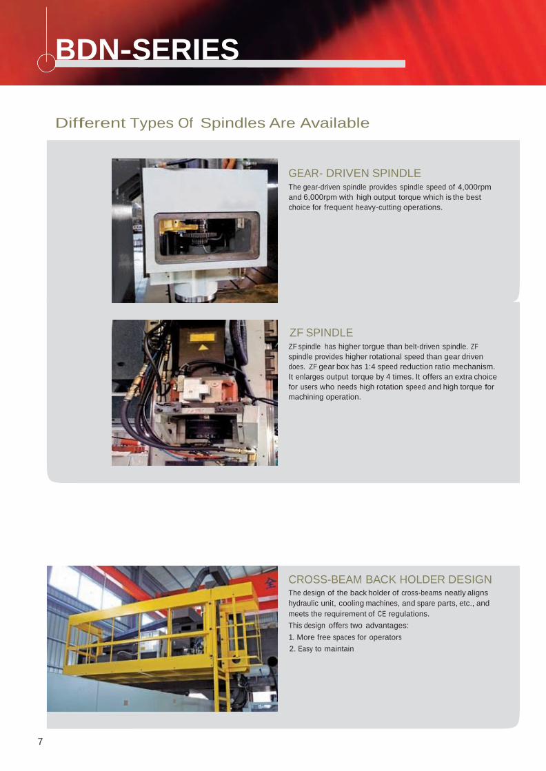
GEAR- DRIVEN SPINDLE The gear-driven spindle provides spindle speed of 4,000rpm
and 6,000rpm with high output torque which is the best
choice for frequent heavy-cutting operations.
ZF SPINDLE ZF spindle has higher torgue than belt-driven spindle. ZF
spindle provides higher rotational speed than gear driven
does. ZF gear box has 1:4 speed reduction ratio mechanism.
It enlarges output torque by 4 times. It offers an extra choice
for users who needs high rotation speed and high torque for
machining operation.
CROSS-BEAM BACK HOLDER DESIGN The design of the back holder of cross-beams neatly aligns
hydraulic unit, cooling machines, and spare parts, etc., and
meets the requirement of CE regulations.
This design offers two advantages:
1. More free spaces for operators
2. Easy to maintain
7
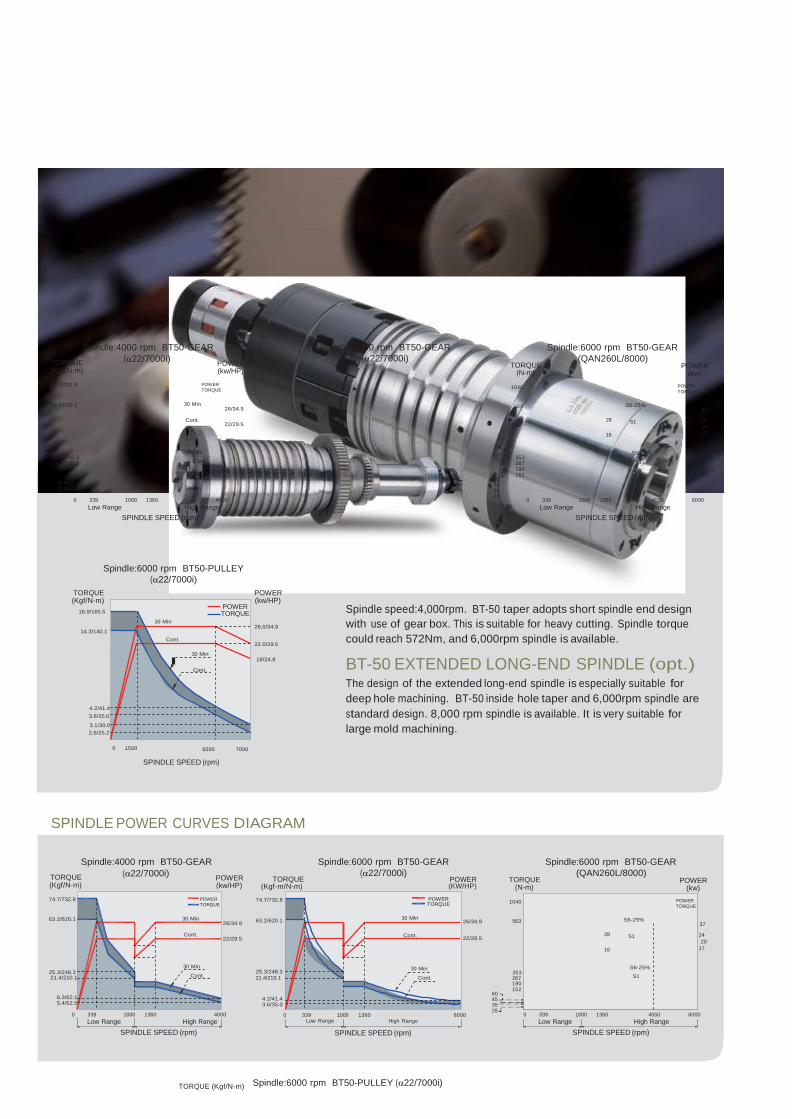
BT-50 SHORT END SPINDLE
Spindle:4000 rpm BT50-GEAR
TORQUE (α22/7000i)
(Kgf/N-m)
POWER (kw/HP)
Spindle:6000 rpm BT50-GEAR
(α22/7000i)
TORQUE
(N-m)
Spindle:6000 rpm BT50-GEAR
(QAN260L/8000)
POWER
(kw)
74.7/732.8
63.2/620.1
30 Min
POWER
TORQUE 26/34.9
1040
563 S6-25%
POWER
TORQUE
37
25.3/248.3 21.4/210.1
6.3/62.1 5.4/52.5
Cont.
30 Min
Cont.
22/29.5
353 267 190 152
60 45 35 28
28 S1 24 20
16 17
S6-25%
S1
0 339 1000 1360 4000
Low Range High Range
SPINDLE SPEED (rpm)
0 339 1000 1360 4550 6000
Low Range High Range
SPINDLE SPEED (rpm)
TORQUE (Kgf/N-m)
Spindle:6000 rpm BT50-PULLEY
(α22/7000i)
POWER (kw/HP)
16.9/165.5
14.3/140.1
4.2/41.4
3.6/35.0
3.1/30.0
2.6/25.2
30 Min
Cont.
30 Min
Cont.
POWER TORQUE
26.0/34.9
22.0/29.5
18/24.8
Spindle speed:4,000rpm. BT-50 taper adopts short spindle end design
with use of gear box. This is suitable for heavy cutting. Spindle torque
could reach 572Nm, and 6,000rpm spindle is available.
BT-50 EXTENDED LONG-END SPINDLE (opt.) The design of the extended long-end spindle is especially suitable for
deep hole machining. BT-50 inside hole taper and 6,000rpm spindle are
standard design. 8,000 rpm spindle is available. It is very suitable for
large mold machining.
0 1500
6000
SPINDLE SPEED (rpm)
7000
SPINDLE POWER CURVES DIAGRAM
Spindle:4000 rpm BT50-GEAR
TORQUE (α22/7000i)
(Kgf/N-m)
POWER (kw/HP)
TORQUE
(Kgf-m/N-m)
Spindle:6000 rpm BT50-GEAR
(α22/7000i) POWER (KW/HP)
TORQUE
(N-m)
Spindle:6000 rpm BT50-GEAR
(QAN260L/8000)
POWER
(kw)
74.7/732.8
63.2/620.1
30 Min
POWER
TORQUE 26/34.9
74.7/732.8
63.2/620.1
30 Min
POWER TORQUE
26/34.9
1040
563 S6-25%
POWER
TORQUE
37
25.3/248.3
Cont.
30 Min
22/29.5
25.3/248.3
Cont.
30 Min
22/29.5
353
28 S1 24 20
16 17
S6-25%
21.4/210.1
6.3/62.1 5.4/52.5
Cont. 21.4/210.1 Cont.
4.2/41.4 3.6/35.0
267 S1 190 152
60 45 35 28
0 339 1000 1360 4000
Low Range High Range 0 339
Low Range 1000 1360
High Range 6000 0 339 1000 1360 4550 6000
Low Range High Range
SPINDLE SPEED (rpm) SPINDLE SPEED (rpm) SPINDLE SPEED (rpm)
TORQUE (Kgf/N-m)
Spindle:6000 rpm BT50-PULLEY (α22/7000i)
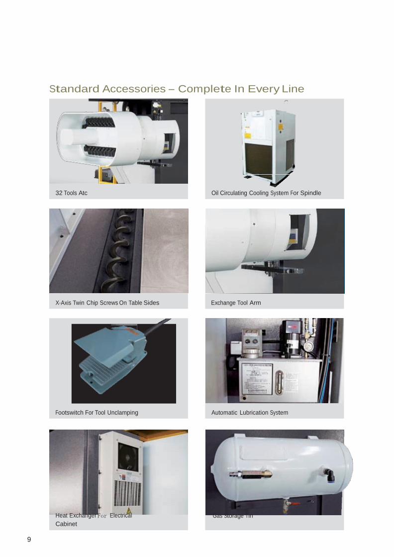
Standard Accessories – Complete In Every Line
32 Tools Atc Oil Circulating Cooling System For Spindle
X-Axis Twin Chip Screws On Table Sides Exchange Tool Arm
Footswitch For Tool Unclamping Automatic Lubrication System
Heat Exchanger For Electrical
Cabinet
Gas Storage Tin
9

All Kinds Of Addition Heads(opt.)
90˚ANGULAR HEAD MULTIANGULAR MILLING
HEAD
EXTEND HEAD (300L/500L)
90° Angular Head Multiangular
Millling Head
Extend head-
300L/500L
Max. Output Power kw(hp) 11 (15) 15 (20)
Spindle Taper BT50 (7/24)
Max. Rotation Speed rpm 3500
Tool Clamping Method Manual Bolt
Index Method Auto 5 degree Index No Index
Option Accessories
90 degree head warehouse beside ATC 90 degree head warehouse on table 60 VERTICAL HORIZONTAL ATC.
10
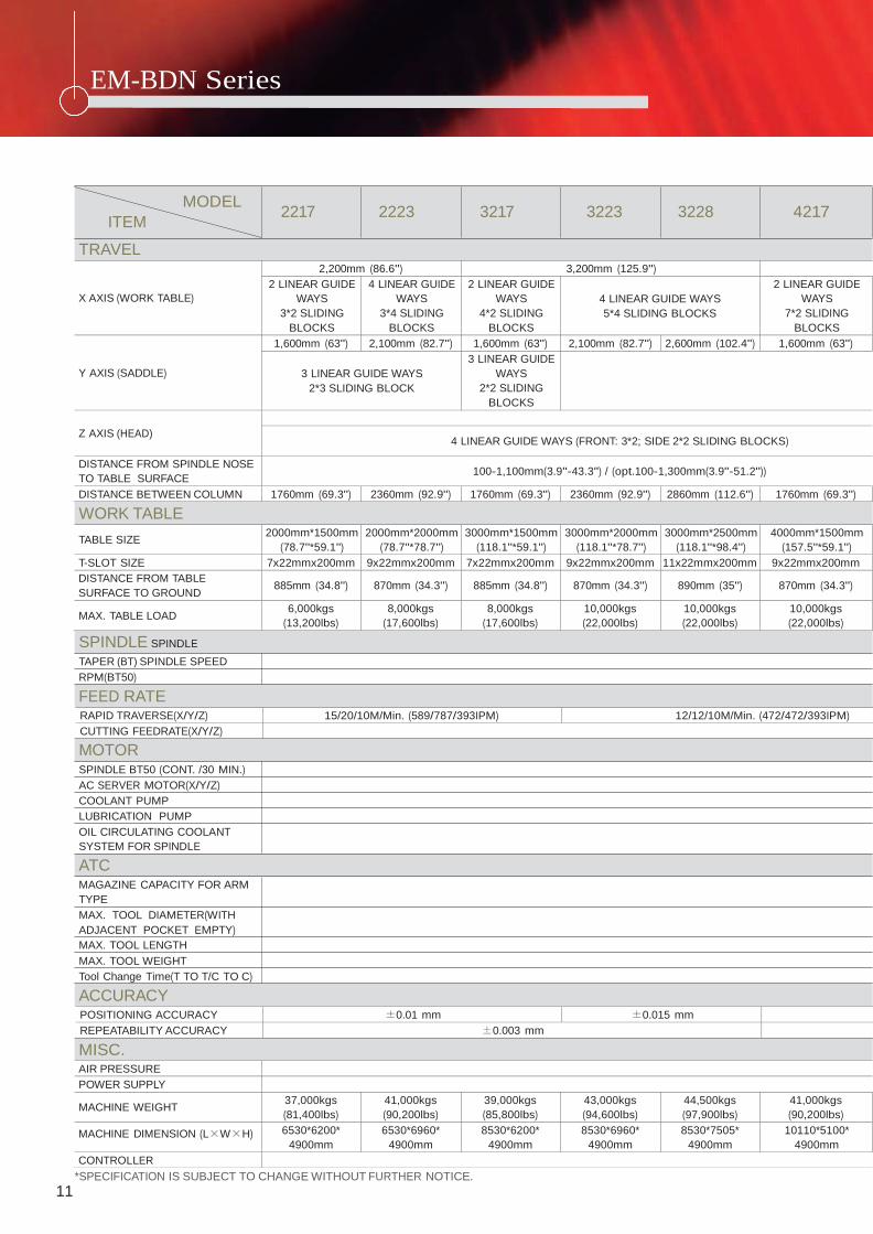
EM-BDN Series Specification
X AXIS (WORK TABLE)
2,200mm (86.6") 3,200mm (125.9") 2 LINEAR GUIDE
WAYS
3*2 SLIDING
BLOCKS
4 LINEAR GUIDE
WAYS
3*4 SLIDING
BLOCKS
2 LINEAR GUIDE
WAYS
4*2 SLIDING
BLOCKS
4 LINEAR GUIDE WAYS
5*4 SLIDING BLOCKS
2 LINEAR GUIDE
WAYS
7*2 SLIDING
BLOCKS Y AXIS (SADDLE)
1,600mm (63") 2,100mm (82.7") 1,600mm (63") 2,100mm (82.7") 2,600mm (102.4") 1,600mm (63")
3 LINEAR GUIDE WAYS
2*3 SLIDING BLOCK
3 LINEAR GUIDE
WAYS
2*2 SLIDING
BLOCKS
Z AXIS (HEAD)
4 LINEAR GUIDE WAYS (FRONT: 3*2; SIDE 2*2 SLIDING BLOCKS)
DISTANCE FROM SPINDLE NOSE
TO TABLE SURFACE
100-1,100mm(3.9"-43.3") / (opt.100-1,300mm(3.9"-51.2"))
DISTANCE BETWEEN COLUMN 1760mm (69.3") 2360mm (92.9") 1760mm (69.3") 2360mm (92.9") 2860mm (112.6") 1760mm (69.3")
TABLE SIZE 2000mm*1500mm
(78.7"*59.1") 2000mm*2000mm
(78.7"*78.7") 3000mm*1500mm
(118.1"*59.1") 3000mm*2000mm
(118.1"*78.7") 3000mm*2500mm
(118.1"*98.4") 4000mm*1500mm
(157.5"*59.1") T-SLOT SIZE 7x22mmx200mm 9x22mmx200mm 7x22mmx200mm 9x22mmx200mm 11x22mmx200mm 9x22mmx200mm DISTANCE FROM TABLE
SURFACE TO GROUND
885mm (34.8")
870mm (34.3")
885mm (34.8")
870mm (34.3")
890mm (35")
870mm (34.3")
MAX. TABLE LOAD 6,000kgs
(13,200lbs) 8,000kgs
(17,600lbs) 8,000kgs
(17,600lbs) 10,000kgs
(22,000lbs) 10,000kgs
(22,000lbs) 10,000kgs
(22,000lbs)
AIR PRESSURE POWER SUPPLY
MACHINE WEIGHT 37,000kgs
(81,400lbs) 41,000kgs
(90,200lbs) 39,000kgs
(85,800lbs) 43,000kgs
(94,600lbs) 44,500kgs
(97,900lbs) 41,000kgs
(90,200lbs) MACHINE DIMENSION (L×W×H) 6530*6200*
4900mm 6530*6960*
4900mm 8530*6200*
4900mm 8530*6960*
4900mm 8530*7505*
4900mm 10110*5100*
4900mm CONTROLLER
MODEL
ITEM 2217 2223 3217 3223 3228 4217
TRAVEL
WORK TABLE
SPINDLE SPINDLE
TAPER (BT) SPINDLE SPEED
RPM(BT50)
FEED RATE
RAPID TRAVERSE(X/Y/Z) 15/20/10M/Min. (589/787/393IPM) 12/12/10M/Min. (472/472/393IPM) CUTTING FEEDRATE(X/Y/Z) MOTOR SPINDLE BT50 (CONT. /30 MIN.)
AC SERVER MOTOR(X/Y/Z)
COOLANT PUMP
LUBRICATION PUMP
OIL CIRCULATING COOLANT
SYSTEM FOR SPINDLE
ATC MAGAZINE CAPACITY FOR ARM
TYPE
MAX. TOOL DIAMETER(WITH
ADJACENT POCKET EMPTY)
MAX. TOOL LENGTH
MAX. TOOL WEIGHT
Tool Change Time(T TO T/C TO C)
ACCURACY
POSITIONING ACCURACY ±0.01 mm ±0.015 mm REPEATABILITY ACCURACY ±0.003 mm MISC.
*SPECIFICATION IS SUBJECT TO CHANGE WITHOUT FURTHER NOTICE.
11
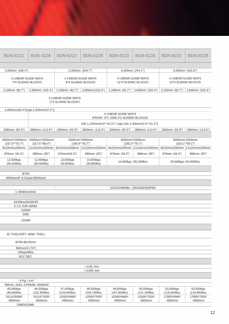
BDN-4223 BDN-4228 BDN-5223 BDN-5228 BDN-6223 BDN-6228 BDN-8223 BDN-8228
4,200mm (165.4") 5,200mm (204.7") 6,200mm (244.1") 8,200mm (322.8")
4 LINEAR GUIDE WAYS
7*4 SLIDING BLOCKS
4 LINEAR GUIDE WAYS
8*4 SLIDING BLOCKS
4 LINEAR GUIDE WAYS
11*4 SLIDING BLOCKS
4 LINEAR GUIDE WAYS
12*4 SLIDING BLOCKS
2,100mm (82.7") 2,600mm (102.4") 2,100mm (82.7") 2,600mm(102.4") 2,100mm (82.7") 2,600mm (102.4") 2,100mm (82.7") 2,600mm (102.4")
3 LINEAR GUIDE WAYS
2*3 SLIDING BLOCKS
1,000mm(39.4")/(opt.1,200mm(47.2"))
4 LINEAR GUIDE WAYS
(FRONT: 3*2; SIDE 2*2 SLIDING BLOCKS)
100-1,100mm(3.9"-43.3") / (opt.100-1,300mm(3.9"-51.2"))
2360mm (92.9") 2860mm (112.6") 2360mm (92.9") 2860mm (112.6") 2360mm (92.9") 2860mm (112.6") 2360mm (92.9") 2860mm (112.6")
4000mm*2000mm
(157.5"*78.7") 4000mm*2500mm
(157.5"*98.4") 5000mm*2000mm
(196.9"*78.7") 6000mm*2000mm
(236.3"*78.7") 8000mm*2000mm
(315.1"*59.1") 9x22mmx200mm 11x22mmx200mm 9x22mmx200mm 11x22mmx200mm 9x22mmx200mm 11x22mmx200mm 9x22mmx200mm 11x22mmx200mm
870mm (34.3")
890mm (35")
870mm(34.3")
890mm (35")
870mm (34.3")
890mm (35")
870mm (34.3")
890mm (35")
12,000kgs
(26,400lbs) 12,000kgs
(26,400lbs) 13,000kgs
28,600lbs) 14,000kgs
(30,800lbs)
16,000kgs (35,200lbs)
20,000kgs (44,000lbs)
BT50
6000rpm(P & G)(opt.8000rpm)
1~8000mm/min
22/26kw(30/35HP)
X,Y,Z:7KW-30NM
1250W
60W
1220W
32 TOOL/(OPT. 40/60 TOOL)
BT50-Ø 125mm
300mm(11.74")
20Kg(44lbs)
8/12 SEC.
10/10/10M/Min. (393/393/393IPM)
±0.02 mm
±0.005 mm
6 Kg / cm²
50KVA, 220V, 3 PHASE, 50/60HZ
45,000kgs
(99,000lbs) 46,500kgs
(102,300lbs) 47,000kgs
(103,400lbs) 48,500kgs
(106,700lbs) 49,000kgs
(107,800lbs) 50,500kgs
(111,100lbs) 53,000kgs
(116,600lbs) 54,500kgs
(119,900lbs) 10110*6960*
4900mm 10110*7505*
4900mm 12000*6960*
4900mm 12000*7505*
4900mm 15300*6960*
4900mm 15300*7505*
4900mm 17800*6960*
4900mm 17800*7505*
4900mm OiMD/31iMB
12
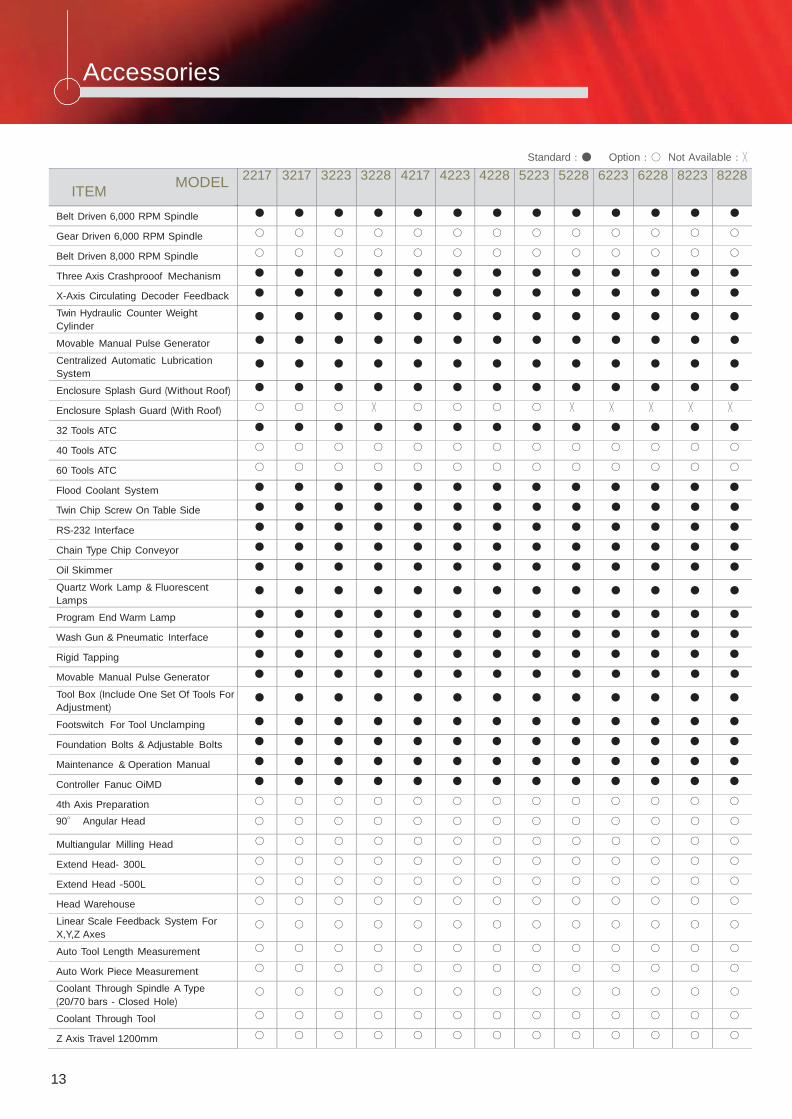
Accessories
Standard:● Option:○ Not Available:╳
ITEM MODEL
2217 3217 3223 3228 4217 4223 4228 5223 5228 6223 6228 8223 8228
Belt Driven 6,000 RPM Spindle ● ● ● ● ● ● ● ● ● ● ● ● ●
Gear Driven 6,000 RPM Spindle ○ ○ ○ ○ ○ ○ ○ ○ ○ ○ ○ ○ ○
Belt Driven 8,000 RPM Spindle ○ ○ ○ ○ ○ ○ ○ ○ ○ ○ ○ ○ ○
Three Axis Crashprooof Mechanism ● ● ● ● ● ● ● ● ● ● ● ● ●
X-Axis Circulating Decoder Feedback ● ● ● ● ● ● ● ● ● ● ● ● ●
Twin Hydraulic Counter Weight
Cylinder ● ● ● ● ● ● ● ● ● ● ● ● ●
Movable Manual Pulse Generator ● ● ● ● ● ● ● ● ● ● ● ● ●
Centralized Automatic Lubrication
System ● ● ● ● ● ● ● ● ● ● ● ● ●
Enclosure Splash Gurd (Without Roof) ● ● ● ● ● ● ● ● ● ● ● ● ●
Enclosure Splash Guard (With Roof) ○ ○ ○ ╳ ○ ○ ○ ○ ╳ ╳ ╳ ╳ ╳
32 Tools ATC ● ● ● ● ● ● ● ● ● ● ● ● ●
40 Tools ATC ○ ○ ○ ○ ○ ○ ○ ○ ○ ○ ○ ○ ○
60 Tools ATC ○ ○ ○ ○ ○ ○ ○ ○ ○ ○ ○ ○ ○
Flood Coolant System ● ● ● ● ● ● ● ● ● ● ● ● ●
Twin Chip Screw On Table Side ● ● ● ● ● ● ● ● ● ● ● ● ●
RS-232 Interface ● ● ● ● ● ● ● ● ● ● ● ● ●
Chain Type Chip Conveyor ● ● ● ● ● ● ● ● ● ● ● ● ●
Oil Skimmer ● ● ● ● ● ● ● ● ● ● ● ● ●
Quartz Work Lamp & Fluorescent
Lamps ● ● ● ● ● ● ● ● ● ● ● ● ●
Program End Warm Lamp ● ● ● ● ● ● ● ● ● ● ● ● ●
Wash Gun & Pneumatic Interface ● ● ● ● ● ● ● ● ● ● ● ● ●
Rigid Tapping ● ● ● ● ● ● ● ● ● ● ● ● ●
Movable Manual Pulse Generator ● ● ● ● ● ● ● ● ● ● ● ● ●
Tool Box (Include One Set Of Tools For
Adjustment) ● ● ● ● ● ● ● ● ● ● ● ● ●
Footswitch For Tool Unclamping ● ● ● ● ● ● ● ● ● ● ● ● ●
Foundation Bolts & Adjustable Bolts ● ● ● ● ● ● ● ● ● ● ● ● ●
Maintenance & Operation Manual ● ● ● ● ● ● ● ● ● ● ● ● ●
Controller Fanuc OiMD ● ● ● ● ● ● ● ● ● ● ● ● ●
4th Axis Preparation ○ ○ ○ ○ ○ ○ ○ ○ ○ ○ ○ ○ ○
90° Angular Head ○ ○ ○ ○ ○ ○ ○ ○ ○ ○ ○ ○ ○
Multiangular Milling Head ○ ○ ○ ○ ○ ○ ○ ○ ○ ○ ○ ○ ○
Extend Head- 300L ○ ○ ○ ○ ○ ○ ○ ○ ○ ○ ○ ○ ○
Extend Head -500L ○ ○ ○ ○ ○ ○ ○ ○ ○ ○ ○ ○ ○
Head Warehouse ○ ○ ○ ○ ○ ○ ○ ○ ○ ○ ○ ○ ○
Linear Scale Feedback System For
X,Y,Z Axes ○ ○ ○ ○ ○ ○ ○ ○ ○ ○ ○ ○ ○
Auto Tool Length Measurement ○ ○ ○ ○ ○ ○ ○ ○ ○ ○ ○ ○ ○
Auto Work Piece Measurement ○ ○ ○ ○ ○ ○ ○ ○ ○ ○ ○ ○ ○
Coolant Through Spindle A Type
(20/70 bars - Closed Hole) ○ ○ ○ ○ ○ ○ ○ ○ ○ ○ ○ ○ ○
Coolant Through Tool ○ ○ ○ ○ ○ ○ ○ ○ ○ ○ ○ ○ ○
Z Axis Travel 1200mm ○ ○ ○ ○ ○ ○ ○ ○ ○ ○ ○ ○ ○
13
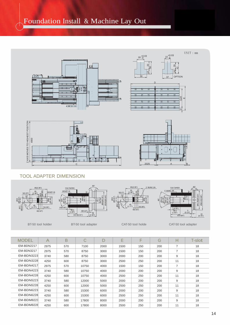
Foundation Install & Machine Lay Out
Ø23
(Ø0.9
1")
Ø
17
(Ø0.6
7")
Z A
XIS
MO
VE
S T
O H
IGH
ES
T P
OS
ITIO
N
49
00
Ø25
(Ø0.9
8")
Ø38
(Ø1.4
9")
60
°
Ø2
5
(Ø0
.98
")
Ø69.8
5
(Ø2.7
5")
25
.7
(1.0
1")
Ø8
5(Ø
3.3
5")
Ø1
00
(Ø3
.94
")
Ø23
(Ø0.9
1")
Ø17
(Ø0.6
7")
26.1
9
(Ø1.0
3")
Ø38
(Ø1.4
9")
1
2
20
5
0
60
°
Ø3
5.0
5
(Ø1
.38
")
Ø2
6.1
9
(Ø1
.03
")
16
26
42
F
GxH
E
Ø69.8
5
(2.7
5")
Ø91.8
5(Ø
3.6
2")
Ø98.4
3(3
.88")
+0.03
22
+0.03 UNIT:mm
18 -0 0
30 37 OPTION
D
C 2025 A B
TOOL ADAPTER DIMENSION
5(0.20")
85(3.35")
35 (1.38")
7/24 TAPER
M24(P=3) M24(P=3)
60° 5(0.2")
85(3.35")
35 (1.38")
1"-8UNC-2A
7/24 TAPER
1"-8UNC-2B
60°
45 (1.77")
8(0.32")
7(0.28")
10(0.39")
46.5
(1.83")
3(0.12")
38
45
(1.77")
7(0.28")
8(0.32")
10
(0.39")
46.5 (1.83")
3
(0.13") 19
101.8(4.01") (1.50") 101.6(4") (0.75")
BT-50 tool holder BT-50 tool adapter CAT-50 tool holde CAT-50 tool adapter
MODEL A B C D E F G H T-slot EM-BDN2217 2975 570 7100 2000 1500 150 200 7 18 EM-BDN3217 2975 570 8750 3000 1500 150 200 7 18 EM-BDN3223 3740 580 8750 3000 2000 200 200 9 18 EM-BDN3228 4250 600 8750 3000 2500 250 200 11 18 EM-BDN4217 2975 570 10750 4000 1500 150 200 7 18 EM-BDN4223 3740 580 10750 4000 2000 200 200 9 18 EM-BDN4228 4250 600 10750 4000 2500 250 200 11 18 EM-BDN5223 3740 580 12000 5000 2000 200 200 9 18 EM-BDN5228 4250 600 12000 5000 2500 250 200 11 18 EM-BDN6223 3740 580 15300 6000 2000 200 200 9 18 EM-BDN6228 4250 600 15300 6000 2500 250 200 11 18 EM-BDM8223 3740 580 17800 8000 2000 200 200 9 18 EM-BDM8228 4250 600 17800 8000 2500 250 200 11 18
14

EVERRISING MACHINERY & AUTOMATION CORP.
10684, 7F, NO. 63 , SEC. 4, HSIN YI RD,
TAIPEI, TAIWAN
T E L : + 8 8 6 -2 – 2704-3366
FA X : + 8 8 6 – 2-2703-4056 E - m a i l : [email protected]
Distributor :