Embed Size (px)
Citation preview
ELTR 110 (AC 1), section 1
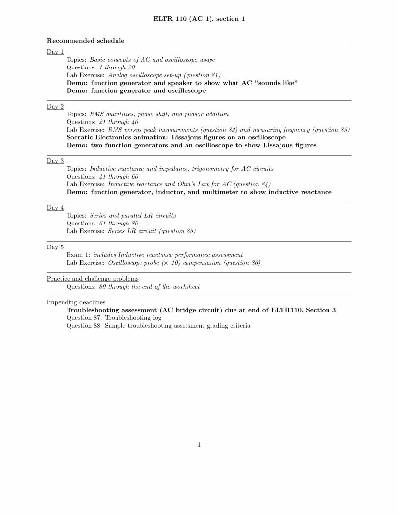
Recommended schedule
Day 1Topics: Basic concepts of AC and oscilloscope usageQuestions: 1 through 20Lab Exercise: Analog oscilloscope set-up (question 81)Demo: function generator and speaker to show what AC ”sounds like”Demo: function generator and oscilloscope
Day 2Topics: RMS quantities, phase shift, and phasor additionQuestions: 21 through 40Lab Exercise: RMS versus peak measurements (question 82) and measuring frequency (question 83)Socratic Electronics animation: Lissajous figures on an oscilloscopeDemo: two function generators and an oscilloscope to show Lissajous figures
Day 3Topics: Inductive reactance and impedance, trigonometry for AC circuitsQuestions: 41 through 60Lab Exercise: Inductive reactance and Ohm’s Law for AC (question 84)Demo: function generator, inductor, and multimeter to show inductive reactance
Day 4Topics: Series and parallel LR circuitsQuestions: 61 through 80Lab Exercise: Series LR circuit (question 85)
Day 5Exam 1: includes Inductive reactance performance assessmentLab Exercise: Oscilloscope probe (× 10) compensation (question 86)
Practice and challenge problemsQuestions: 89 through the end of the worksheet
Impending deadlinesTroubleshooting assessment (AC bridge circuit) due at end of ELTR110, Section 3Question 87: Troubleshooting logQuestion 88: Sample troubleshooting assessment grading criteria
1

ELTR 110 (AC 1), section 1
Skill standards addressed by this course section
EIA Raising the Standard; Electronics Technician Skills for Today and Tomorrow, June 1994
C Technical Skills – AC circuitsC.01 Demonstrate an understanding of sources of electricity in AC circuits.C.02 Demonstrate an understanding of the properties of an AC signal.C.03 Demonstrate an understanding of the principles of operation and characteristics of sinusoidal and non-
sinusoidal wave forms.C.05 Demonstrate an understanding of measurement of power in AC circuits.C.11 Understand principles and operations of AC inductive circuits.C.12 Fabricate and demonstrate AC inductive circuits.C.13 Troubleshoot and repair AC inductive circuits.
B Basic and Practical Skills – Communicating on the JobB.01 Use effective written and other communication skills. Met by group discussion and completion of labwork.B.03 Employ appropriate skills for gathering and retaining information. Met by research and preparation
prior to group discussion.B.04 Interpret written, graphic, and oral instructions. Met by completion of labwork.B.06 Use language appropriate to the situation. Met by group discussion and in explaining completed labwork.B.07 Participate in meetings in a positive and constructive manner. Met by group discussion.B.08 Use job-related terminology. Met by group discussion and in explaining completed labwork.B.10 Document work projects, procedures, tests, and equipment failures. Met by project construction and/or
troubleshooting assessments.C Basic and Practical Skills – Solving Problems and Critical Thinking
C.01 Identify the problem. Met by research and preparation prior to group discussion.C.03 Identify available solutions and their impact including evaluating credibility of information, and locating
information. Met by research and preparation prior to group discussion.C.07 Organize personal workloads. Met by daily labwork, preparatory research, and project management.C.08 Participate in brainstorming sessions to generate new ideas and solve problems. Met by group discussion.
D Basic and Practical Skills – ReadingD.01 Read and apply various sources of technical information (e.g. manufacturer literature, codes, and
regulations). Met by research and preparation prior to group discussion.E Basic and Practical Skills – Proficiency in Mathematics
E.01 Determine if a solution is reasonable.E.02 Demonstrate ability to use a simple electronic calculator.E.05 Solve problems and [sic] make applications involving integers, fractions, decimals, percentages, and
ratios using order of operations.E.06 Translate written and/or verbal statements into mathematical expressions.E.09 Read scale on measurement device(s) and make interpolations where appropriate. Met by oscilloscope
usage.E.12 Interpret and use tables, charts, maps, and/or graphs.E.13 Identify patterns, note trends, and/or draw conclusions from tables, charts, maps, and/or graphs.E.15 Simplify and solve algebraic expressions and formulas.E.16 Select and use formulas appropriately.E.17 Understand and use scientific notation.E.20 Graph functions.E.26 Apply Pythagorean theorem.E.27 Identify basic functions of sine, cosine, and tangent.E.28 Compute and solve problems using basic trigonometric functions.
2
ELTR 110 (AC 1), section 1
Common areas of confusion for students
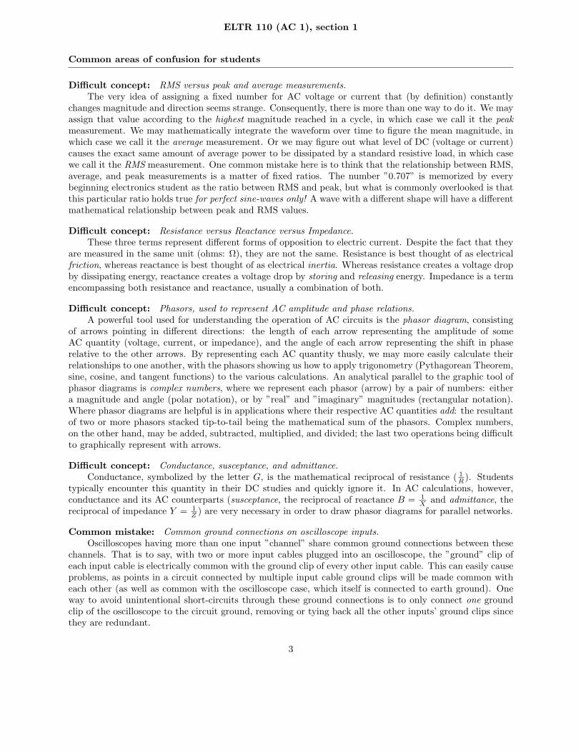
Difficult concept: RMS versus peak and average measurements.The very idea of assigning a fixed number for AC voltage or current that (by definition) constantly
changes magnitude and direction seems strange. Consequently, there is more than one way to do it. We mayassign that value according to the highest magnitude reached in a cycle, in which case we call it the peakmeasurement. We may mathematically integrate the waveform over time to figure the mean magnitude, inwhich case we call it the average measurement. Or we may figure out what level of DC (voltage or current)causes the exact same amount of average power to be dissipated by a standard resistive load, in which casewe call it the RMS measurement. One common mistake here is to think that the relationship between RMS,average, and peak measurements is a matter of fixed ratios. The number ”0.707” is memorized by everybeginning electronics student as the ratio between RMS and peak, but what is commonly overlooked is thatthis particular ratio holds true for perfect sine-waves only! A wave with a different shape will have a differentmathematical relationship between peak and RMS values.
Difficult concept: Resistance versus Reactance versus Impedance.These three terms represent different forms of opposition to electric current. Despite the fact that they
are measured in the same unit (ohms: Ω), they are not the same. Resistance is best thought of as electricalfriction, whereas reactance is best thought of as electrical inertia. Whereas resistance creates a voltage dropby dissipating energy, reactance creates a voltage drop by storing and releasing energy. Impedance is a termencompassing both resistance and reactance, usually a combination of both.
Difficult concept: Phasors, used to represent AC amplitude and phase relations.A powerful tool used for understanding the operation of AC circuits is the phasor diagram, consisting
of arrows pointing in different directions: the length of each arrow representing the amplitude of someAC quantity (voltage, current, or impedance), and the angle of each arrow representing the shift in phaserelative to the other arrows. By representing each AC quantity thusly, we may more easily calculate theirrelationships to one another, with the phasors showing us how to apply trigonometry (Pythagorean Theorem,sine, cosine, and tangent functions) to the various calculations. An analytical parallel to the graphic tool ofphasor diagrams is complex numbers, where we represent each phasor (arrow) by a pair of numbers: eithera magnitude and angle (polar notation), or by ”real” and ”imaginary” magnitudes (rectangular notation).Where phasor diagrams are helpful is in applications where their respective AC quantities add: the resultantof two or more phasors stacked tip-to-tail being the mathematical sum of the phasors. Complex numbers,on the other hand, may be added, subtracted, multiplied, and divided; the last two operations being difficultto graphically represent with arrows.
Difficult concept: Conductance, susceptance, and admittance.Conductance, symbolized by the letter G, is the mathematical reciprocal of resistance ( 1
R). Students
typically encounter this quantity in their DC studies and quickly ignore it. In AC calculations, however,conductance and its AC counterparts (susceptance, the reciprocal of reactance B = 1
Xand admittance, the
reciprocal of impedance Y = 1
Z) are very necessary in order to draw phasor diagrams for parallel networks.
Common mistake: Common ground connections on oscilloscope inputs.Oscilloscopes having more than one input ”channel” share common ground connections between these
channels. That is to say, with two or more input cables plugged into an oscilloscope, the ”ground” clip ofeach input cable is electrically common with the ground clip of every other input cable. This can easily causeproblems, as points in a circuit connected by multiple input cable ground clips will be made common witheach other (as well as common with the oscilloscope case, which itself is connected to earth ground). Oneway to avoid unintentional short-circuits through these ground connections is to only connect one groundclip of the oscilloscope to the circuit ground, removing or tying back all the other inputs’ ground clips sincethey are redundant.
3

Question 1
What is the difference between DC and AC electricity? Identify some common sources of each type ofelectricity.
file 00028
Answer 1
DC is an acronym meaning Direct Current: that is, electrical current that moves in one direction only.AC is an acronym meaning Alternating Current: that is, electrical current that periodically reverses direction(”alternates”).
Electrochemical batteries generate DC, as do solar cells. Microphones generate AC when sensing soundwaves (vibrations of air molecules). There are many, many other sources of DC and AC electricity thanwhat I have mentioned here!
Notes 1
Discuss a bit of the history of AC versus DC in early power systems. In the early days of electric powerin the United States of America, there was a heated debate between the use of DC versus AC. ThomasEdison championed DC, while George Westinghouse and Nikola Tesla advocated AC.
It might be worthwhile to mention that almost all the electric power in the world is generated anddistributed as AC (Alternating Current), and not as DC (in other words, Thomas Edison lost the AC/DCbattle!). Depending on the level of the class you are teaching, this may or may not be a good time to explainwhy most power systems use AC. Either way, your students will probably ask why, so you should be preparedto address this question in some way (or have them report any findings of their own!).
4
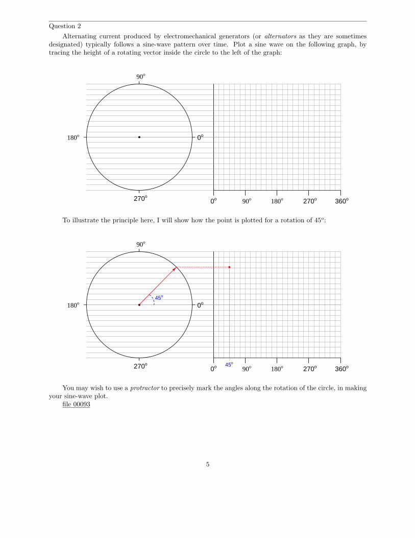
Question 2
Alternating current produced by electromechanical generators (or alternators as they are sometimesdesignated) typically follows a sine-wave pattern over time. Plot a sine wave on the following graph, bytracing the height of a rotating vector inside the circle to the left of the graph:
180o90o0o 270o 360o
90o
180o
270o
0o
To illustrate the principle here, I will show how the point is plotted for a rotation of 45o:
180o90o0o 270o 360o
90o
180o
270o
0o
45o
45o
You may wish to use a protractor to precisely mark the angles along the rotation of the circle, in makingyour sine-wave plot.
file 00093
5
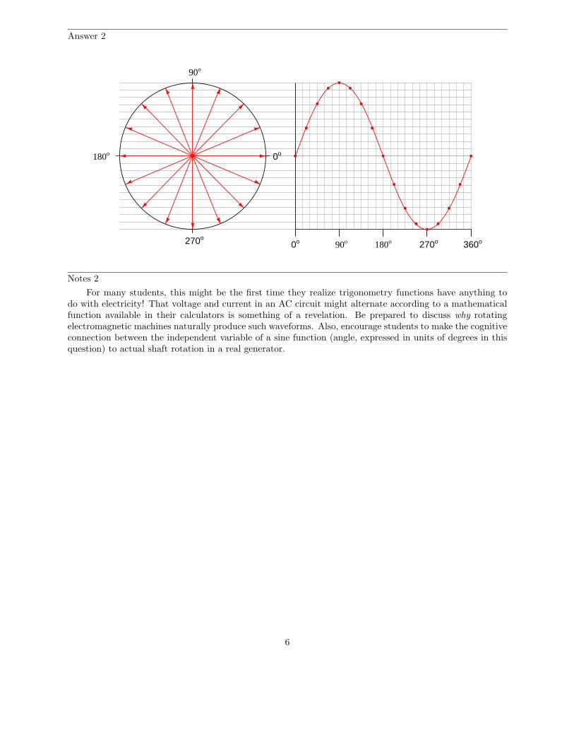
Answer 2
180o90o0o 270o 360o
90o
180o
270o
0o
Notes 2
For many students, this might be the first time they realize trigonometry functions have anything todo with electricity! That voltage and current in an AC circuit might alternate according to a mathematicalfunction available in their calculators is something of a revelation. Be prepared to discuss why rotatingelectromagnetic machines naturally produce such waveforms. Also, encourage students to make the cognitiveconnection between the independent variable of a sine function (angle, expressed in units of degrees in thisquestion) to actual shaft rotation in a real generator.
6
Question 3
All other factors being equal, which possesses a greater potential for inducing harmful electric shock,DC electricity or AC electricity at a frequency of 60 Hertz? Be sure to back up your answer with researchdata!
file 03289
Answer 3
From a perspective of inducing electric shock, AC has been experimentally proven to possess greaterhazard than DC (all other factors being equal). See the research of Charles Dalziel for supporting data.
Notes 3
A common misconception is that DC is more capable of delivering a harmful electric shock than AC, allother factors being equal. In fact, this is something I used to teach myself (because I had heard it numeroustimes from others) before I discovered the research of Charles Dalziel. One of the explanations used tosupport the myth of DC being more dangerous is that DC has the ability to cause muscle tetanus morereadily than AC. However, at 60 Hertz, the reversals of polarity occur so quickly that no human musclecould relax fast enough to enable a shock victim to release a ”hot” wire anyway, so that fact that AC stopsmultiple times per second is of no benefit to the victim.
Do not be surprised if some students react unfavorably to the answer given here! The myth that DC ismore dangerous than AC is so prevalent, especially among people who have a little background knowledgeof the subject, that to counter it is to invite dispute. This is why I included the condition of supporting anyanswer by research data in the question.
This just goes to show that there are many misconceptions about electricity that are passed from personto person as ”common knowledge” which have little or no grounding in fact (lightning never strikes twicein the same spot, electricity takes the least path of resistance, high current is more dangerous than highvoltage, etc., etc.). The study of electricity and electronics is science, and in science experimental data isour sole authority. One of the most important lessons to be learned in science is that human beings havea propensity to believe things which are not true, and some will continue to defend false beliefs even in theface of conclusive evidence.
7
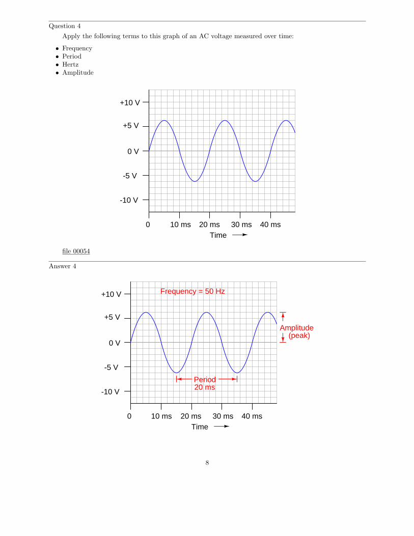
Question 4
Apply the following terms to this graph of an AC voltage measured over time:
• Frequency• Period• Hertz• Amplitude
Time0 10 ms 20 ms 30 ms 40 ms
+5 V
+10 V
-5 V
-10 V
0 V
file 00054
Answer 4
Time0 10 ms 20 ms 30 ms 40 ms
+5 V
+10 V
-5 V
-10 V
0 V
Amplitude(peak)
Period20 ms
Frequency = 50 Hz
8

Notes 4
As always, it is more important to be able to apply a term to a real-life example than it is to memorizea definition for that term. In my experience, many students prefer to memorize definitions for terms ratherthan to go through the trouble of understanding how those terms apply to real life. Make sure studentsrealize just how and why these AC terms apply to a waveform such as this.
9

Question 5
Frequency used to be expressed in units of cycles per second, abbreviated as CPS. Now, the standardizedunit is Hertz. Explain the meaning of the obsolete frequency unit: what, exactly, does it mean for an ACvoltage or current to have x number of ”cycles per second?”
file 00053
Answer 5
Each time an AC voltage or current repeats itself, that interval is called a cycle. Frequency, beingthe rate at which an AC voltage or current repeats itself over time, may be represented in terms of cycles(repetitions) per second.
Notes 5
Encourage your students to discuss the origins of the new unit (Hertz), and how it actually communicatesless information about the thing being measured than the old unit (CPS).
10

Question 6
If an AC voltage has a frequency of 350 Hz, how long (in time) is its period?file 00055
Answer 6
Period = 2.8571 milliseconds
Notes 6
It is important for students to realize the reciprocal relationship between frequency and period. One iscycles per second while the other is seconds per cycle.
11

Question 7
Radio waves are comprised of oscillating electric and magnetic fields, which radiate away from sourcesof high-frequency AC at (nearly) the speed of light. An important measure of a radio wave is its wavelength,defined as the distance the wave travels in one complete cycle.
Suppose a radio transmitter operates at a fixed frequency of 950 kHz. Calculate the approximatewavelength (λ) of the radio waves emanating from the transmitter tower, in the metric distance unit ofmeters. Also, write the equation you used to solve for λ.
file 01819
Answer 7
λ ≈ 316 meters
I’ll let you find the equation on your own!
Notes 7
I purposely omit the velocity of light, as well as the time/distance/velocity equation, so that studentswill have to do some simple research this calculate this value. Neither of these concepts is beyond high-schoollevel science students, and should pose no difficulty at all for college-level students to find on their own.
12
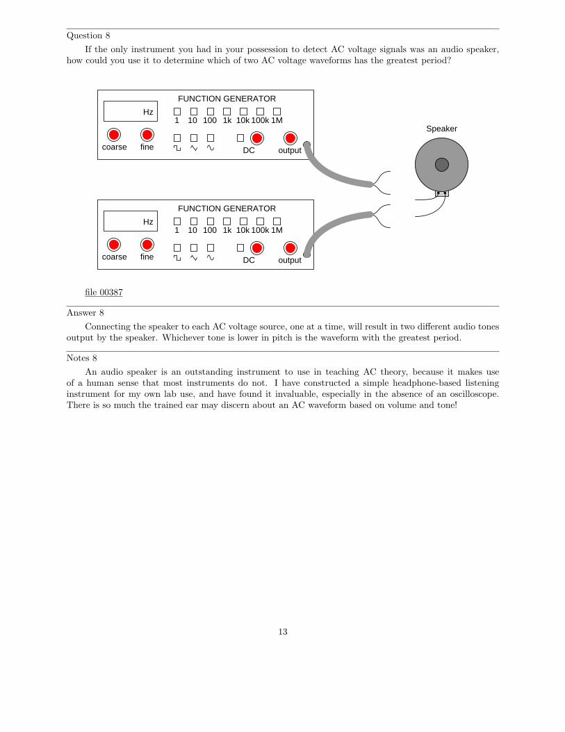
Question 8
If the only instrument you had in your possession to detect AC voltage signals was an audio speaker,how could you use it to determine which of two AC voltage waveforms has the greatest period?
Hz
FUNCTION GENERATOR
1 10 100 1k 10k 100k 1M
outputDCfinecoarse
Hz
FUNCTION GENERATOR
1 10 100 1k 10k 100k 1M
outputDCfinecoarse
Speaker
file 00387
Answer 8
Connecting the speaker to each AC voltage source, one at a time, will result in two different audio tonesoutput by the speaker. Whichever tone is lower in pitch is the waveform with the greatest period.
Notes 8
An audio speaker is an outstanding instrument to use in teaching AC theory, because it makes useof a human sense that most instruments do not. I have constructed a simple headphone-based listeninginstrument for my own lab use, and have found it invaluable, especially in the absence of an oscilloscope.There is so much the trained ear may discern about an AC waveform based on volume and tone!
13
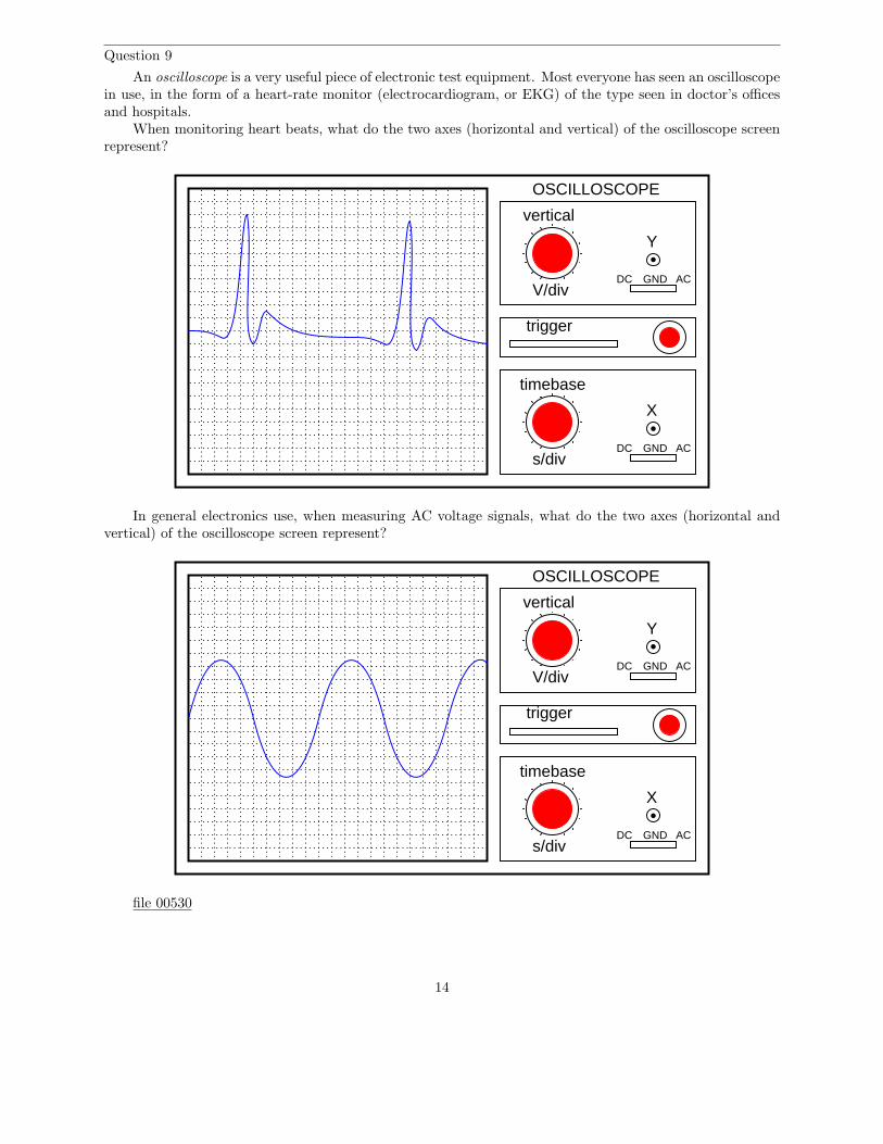
Question 9
An oscilloscope is a very useful piece of electronic test equipment. Most everyone has seen an oscilloscopein use, in the form of a heart-rate monitor (electrocardiogram, or EKG) of the type seen in doctor’s officesand hospitals.
When monitoring heart beats, what do the two axes (horizontal and vertical) of the oscilloscope screenrepresent?
trigger
timebase
s/divDC GND AC
X
GNDDCV/div
vertical
OSCILLOSCOPE
Y
AC
In general electronics use, when measuring AC voltage signals, what do the two axes (horizontal andvertical) of the oscilloscope screen represent?
trigger
timebase
s/divDC GND AC
X
GNDDCV/div
vertical
OSCILLOSCOPE
Y
AC
file 00530
14

Answer 9
EKG vertical = heart muscle contraction ; EKG horizontal = timeGeneral-purpose vertical = voltage ; General-purpose horizontal = time
Notes 9
Oscilloscope function is often best learned through interaction. Be sure to have at least one oscilloscopeoperational in the classroom for student interaction during discussion time.
15
Question 10
The core of an analog oscilloscope is a special type of vacuum tube known as a Cathode Ray Tube, orCRT. While similar in function to the CRT used in televisions, oscilloscope display tubes are specially builtfor the purpose of serving an a measuring instrument.
Explain how a CRT functions. What goes on inside the tube to produce waveform displays on thescreen?
file 00536
Answer 10
There are many tutorials and excellent reference books on CRT function – go read a few of them!
Notes 10
Some of your students may come across photographs and illustrations of CRTs for use in theirpresentation. If at all possible, provide a way for individual students to share their visual findings with theirclassmates, through the use of an overhead projector, computer monitor, or computer projector. Discussin detail the operation of a CRT with your students, especially noting the electrostatic method of electronbeam deflection used to ”steer” the beam to specific areas on the screen.
16
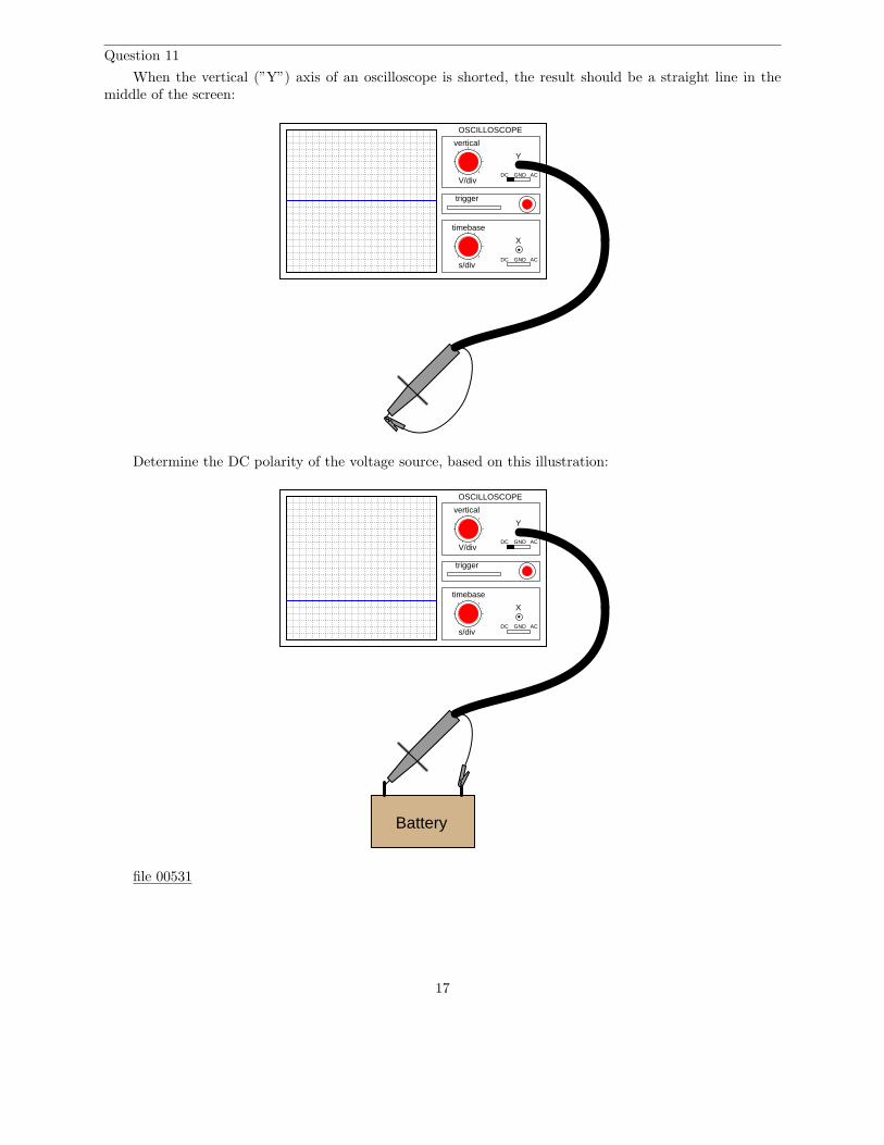
Question 11
When the vertical (”Y”) axis of an oscilloscope is shorted, the result should be a straight line in themiddle of the screen:
trigger
timebase
s/divDC GND AC
X
GNDDCV/div
vertical
OSCILLOSCOPE
Y
AC
Determine the DC polarity of the voltage source, based on this illustration:
trigger
timebase
s/divDC GND AC
X
GNDDCV/div
vertical
OSCILLOSCOPE
Y
AC
Battery
file 00531
17
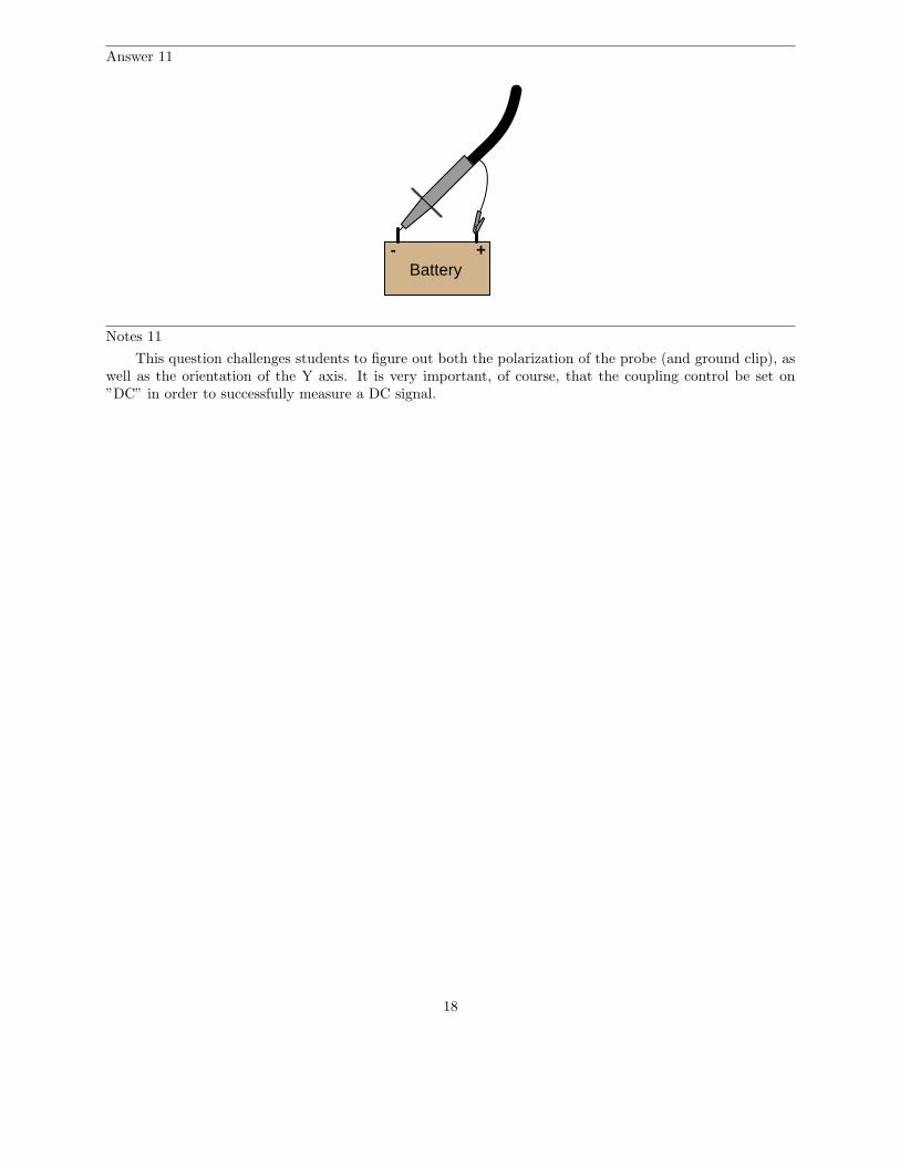
Answer 11
Battery- +
Notes 11
This question challenges students to figure out both the polarization of the probe (and ground clip), aswell as the orientation of the Y axis. It is very important, of course, that the coupling control be set on”DC” in order to successfully measure a DC signal.
18
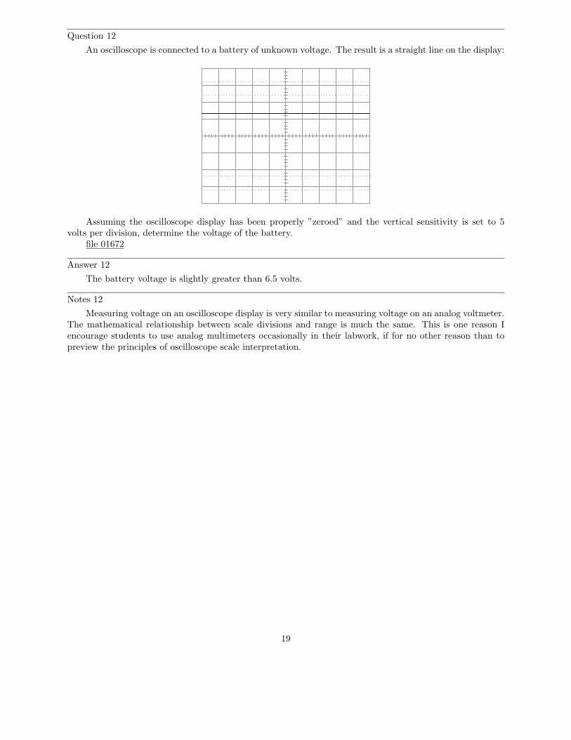
Question 12
An oscilloscope is connected to a battery of unknown voltage. The result is a straight line on the display:
Assuming the oscilloscope display has been properly ”zeroed” and the vertical sensitivity is set to 5volts per division, determine the voltage of the battery.
file 01672
Answer 12
The battery voltage is slightly greater than 6.5 volts.
Notes 12
Measuring voltage on an oscilloscope display is very similar to measuring voltage on an analog voltmeter.The mathematical relationship between scale divisions and range is much the same. This is one reason Iencourage students to use analog multimeters occasionally in their labwork, if for no other reason than topreview the principles of oscilloscope scale interpretation.
19
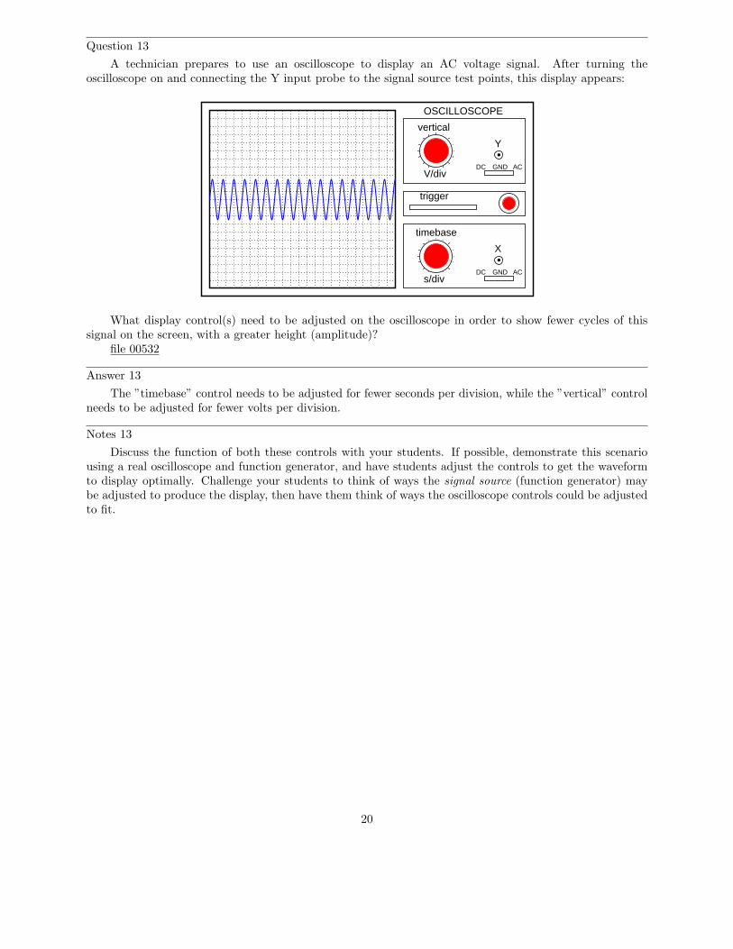
Question 13
A technician prepares to use an oscilloscope to display an AC voltage signal. After turning theoscilloscope on and connecting the Y input probe to the signal source test points, this display appears:
trigger
timebase
s/divDC GND AC
X
GNDDCV/div
vertical
OSCILLOSCOPE
Y
AC
What display control(s) need to be adjusted on the oscilloscope in order to show fewer cycles of thissignal on the screen, with a greater height (amplitude)?
file 00532
Answer 13
The ”timebase” control needs to be adjusted for fewer seconds per division, while the ”vertical” controlneeds to be adjusted for fewer volts per division.
Notes 13
Discuss the function of both these controls with your students. If possible, demonstrate this scenariousing a real oscilloscope and function generator, and have students adjust the controls to get the waveformto display optimally. Challenge your students to think of ways the signal source (function generator) maybe adjusted to produce the display, then have them think of ways the oscilloscope controls could be adjustedto fit.
20
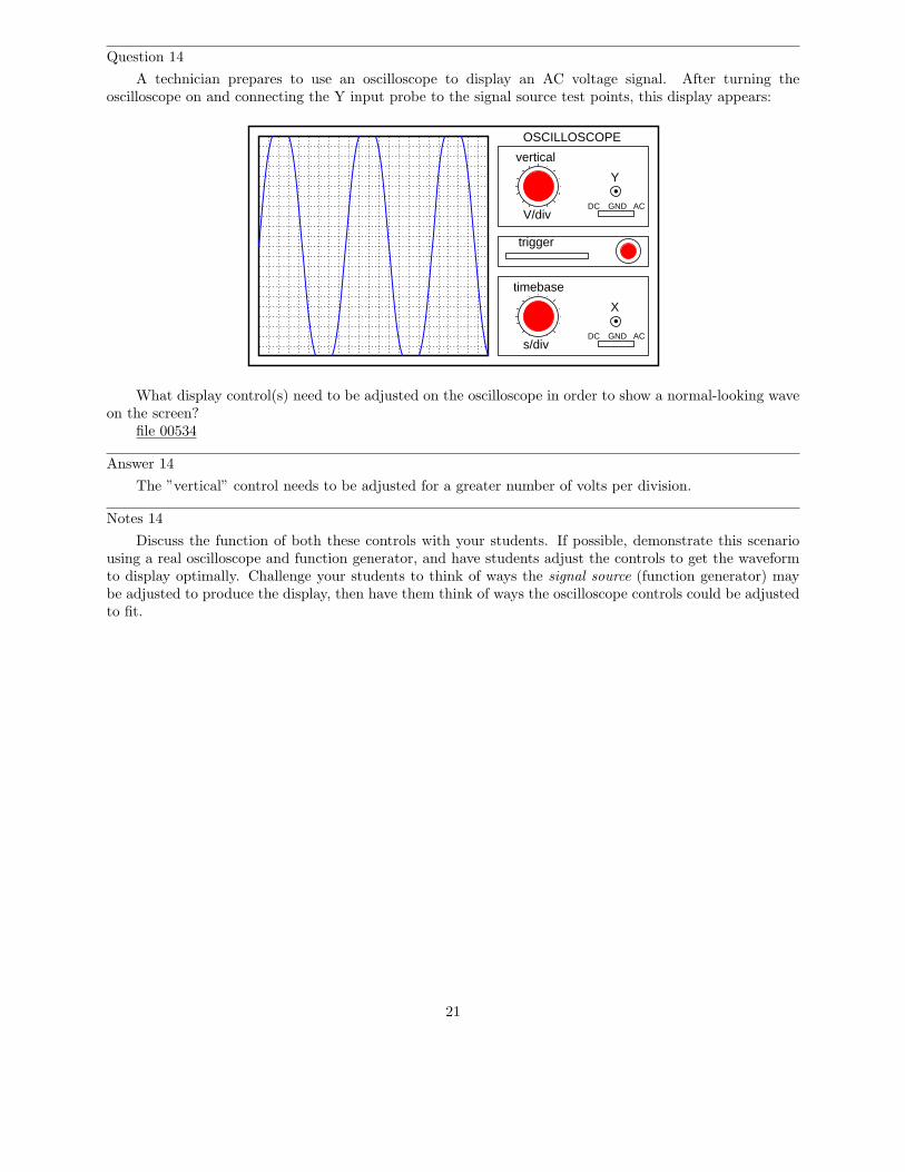
Question 14
A technician prepares to use an oscilloscope to display an AC voltage signal. After turning theoscilloscope on and connecting the Y input probe to the signal source test points, this display appears:
trigger
timebase
s/divDC GND AC
X
GNDDCV/div
vertical
OSCILLOSCOPE
Y
AC
What display control(s) need to be adjusted on the oscilloscope in order to show a normal-looking waveon the screen?
file 00534
Answer 14
The ”vertical” control needs to be adjusted for a greater number of volts per division.
Notes 14
Discuss the function of both these controls with your students. If possible, demonstrate this scenariousing a real oscilloscope and function generator, and have students adjust the controls to get the waveformto display optimally. Challenge your students to think of ways the signal source (function generator) maybe adjusted to produce the display, then have them think of ways the oscilloscope controls could be adjustedto fit.
21
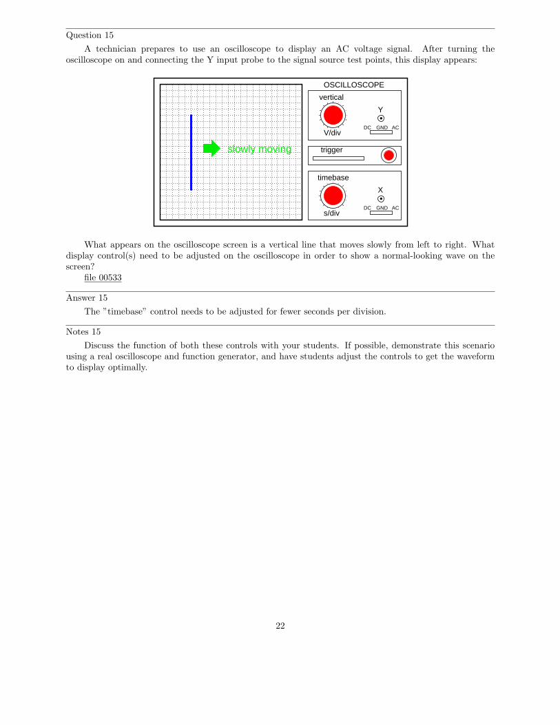
Question 15
A technician prepares to use an oscilloscope to display an AC voltage signal. After turning theoscilloscope on and connecting the Y input probe to the signal source test points, this display appears:
trigger
timebase
s/divDC GND AC
X
GNDDCV/div
vertical
OSCILLOSCOPE
Y
AC
slowly moving
What appears on the oscilloscope screen is a vertical line that moves slowly from left to right. Whatdisplay control(s) need to be adjusted on the oscilloscope in order to show a normal-looking wave on thescreen?
file 00533
Answer 15
The ”timebase” control needs to be adjusted for fewer seconds per division.
Notes 15
Discuss the function of both these controls with your students. If possible, demonstrate this scenariousing a real oscilloscope and function generator, and have students adjust the controls to get the waveformto display optimally.
22
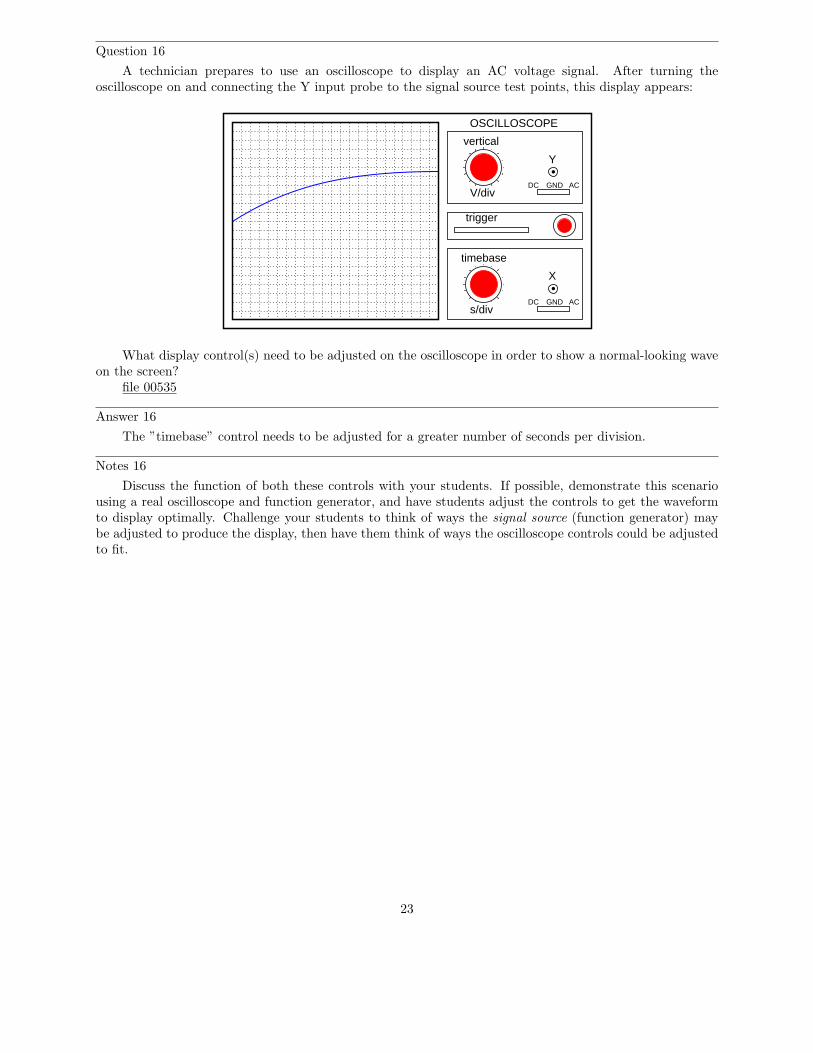
Question 16
A technician prepares to use an oscilloscope to display an AC voltage signal. After turning theoscilloscope on and connecting the Y input probe to the signal source test points, this display appears:
trigger
timebase
s/divDC GND AC
X
GNDDCV/div
vertical
OSCILLOSCOPE
Y
AC
What display control(s) need to be adjusted on the oscilloscope in order to show a normal-looking waveon the screen?
file 00535
Answer 16
The ”timebase” control needs to be adjusted for a greater number of seconds per division.
Notes 16
Discuss the function of both these controls with your students. If possible, demonstrate this scenariousing a real oscilloscope and function generator, and have students adjust the controls to get the waveformto display optimally. Challenge your students to think of ways the signal source (function generator) maybe adjusted to produce the display, then have them think of ways the oscilloscope controls could be adjustedto fit.
23
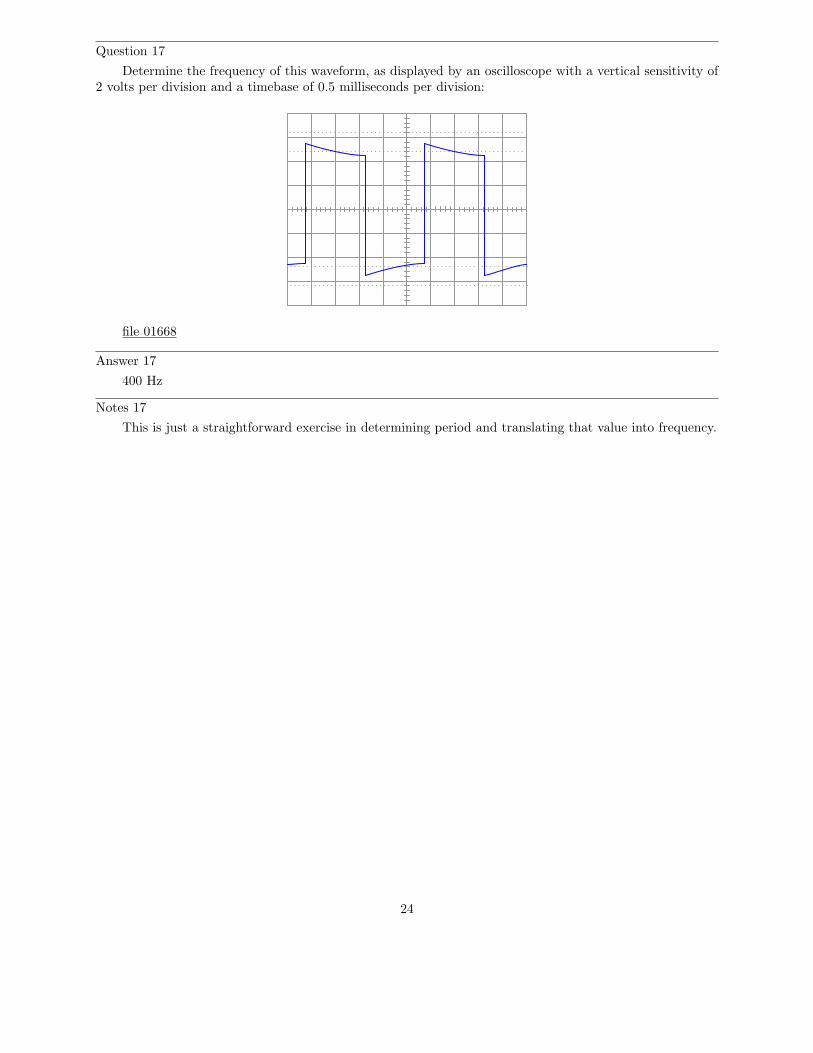
Question 17
Determine the frequency of this waveform, as displayed by an oscilloscope with a vertical sensitivity of2 volts per division and a timebase of 0.5 milliseconds per division:
file 01668
Answer 17
400 Hz
Notes 17
This is just a straightforward exercise in determining period and translating that value into frequency.
24

Question 18
Assuming the vertical sensitivity control is set to 2 volts per division, and the timebase control is set to10 µs per division, calculate the amplitude of this ”sawtooth” wave (in volts peak and volts peak-to-peak)as well as its frequency.
trigger
timebase
s/divDC GND AC
X
GNDDCV/div
vertical
OSCILLOSCOPE
Y
AC
file 00541
Answer 18
Epeak = 8 VEpeak−to−peak = 16 Vf = 6.67 kHz
Notes 18
This question is not only good for introducing basic oscilloscope principles, but it is also excellent forreview of AC waveform measurements.
25
Question 19
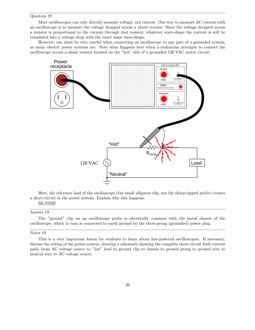
Most oscilloscopes can only directly measure voltage, not current. One way to measure AC current withan oscilloscope is to measure the voltage dropped across a shunt resistor. Since the voltage dropped acrossa resistor is proportional to the current through that resistor, whatever wave-shape the current is will betranslated into a voltage drop with the exact same wave-shape.
However, one must be very careful when connecting an oscilloscope to any part of a grounded system,as many electric power systems are. Note what happens here when a technician attempts to connect theoscilloscope across a shunt resistor located on the ”hot” side of a grounded 120 VAC motor circuit:
Load
Powerreceptacle
Rshunt
trigger
timebase
s/divDC GND AC
X
GNDDCV/div
vertical
OSCILLOSCOPE
Y
AC
120 VAC
"Hot"
"Neutral"
Here, the reference lead of the oscilloscope (the small alligator clip, not the sharp-tipped probe) createsa short-circuit in the power system. Explain why this happens.
file 01820
Answer 19
The ”ground” clip on an oscilloscope probe is electrically common with the metal chassis of theoscilloscope, which in turn is connected to earth ground by the three-prong (grounded) power plug.
Notes 19
This is a very important lesson for students to learn about line-powered oscilloscopes. If necessary,discuss the wiring of the power system, drawing a schematic showing the complete short-circuit fault currentpath, from AC voltage source to ”hot” lead to ground clip to chassis to ground prong to ground wire toneutral wire to AC voltage source.
26
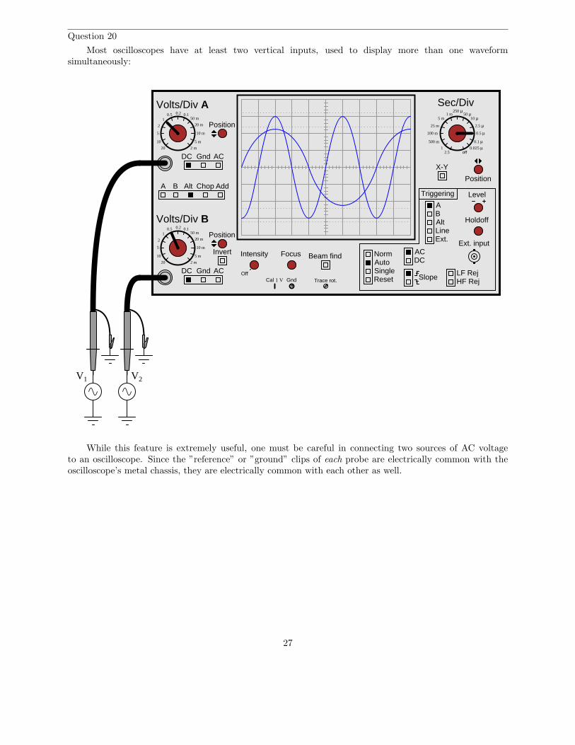
Question 20
Most oscilloscopes have at least two vertical inputs, used to display more than one waveformsimultaneously:
A B Alt Chop Add
Volts/Div A
Volts/Div B
DC Gnd AC
DC Gnd AC
Invert Intensity Focus
Position
Position
Position
Off
Beam find
LineExt.
AB
ACDC
NormAutoSingle
Slope
Level
Reset
X-Y
Holdoff
LF RejHF Rej
Triggering
Alt
Ext. input
Cal 1 V Gnd Trace rot.
Sec/Div0.5 0.2 0.1
1
10
5
2
20
50 m
20 m
10 m
5 m
2 m
0.5 0.2 0.11
10
5
2
20
50 m
20 m
10 m
5 m
2 m
1 m5 m
25 m
100 m
500 m
2.51
250 µ50 µ
10 µ
2.5 µ
0.5 µ
0.1 µ0.025 µ
off
V1 V2
While this feature is extremely useful, one must be careful in connecting two sources of AC voltageto an oscilloscope. Since the ”reference” or ”ground” clips of each probe are electrically common with theoscilloscope’s metal chassis, they are electrically common with each other as well.
27
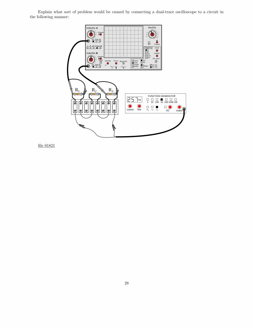
Explain what sort of problem would be caused by connecting a dual-trace oscilloscope to a circuit inthe following manner:
A B Alt Chop Add
Volts/Div A
Volts/Div B
DC Gnd AC
DC Gnd AC
Invert Intensity Focus
Position
Position
Position
Off
Beam find
LineExt.
AB
ACDC
NormAutoSingle
Slope
Level
Reset
X-Y
Holdoff
LF RejHF Rej
Triggering
Alt
Ext. input
Cal 1 V Gnd Trace rot.
Sec/Div0.5 0.2 0.1
1
10
5
2
20
50 m
20 m
10 m
5 m
2 m
0.5 0.2 0.11
10
5
2
20
50 m
20 m
10 m
5 m
2 m
1 m5 m
25 m
100 m
500 m
2.51
250 µ50 µ
10 µ
2.5 µ
0.5 µ
0.1 µ0.025 µ
off
Hz
FUNCTION GENERATOR
1 10 100 1k 10k 100k 1M
outputDCfinecoarse
R1 R2 R3
file 01821
28
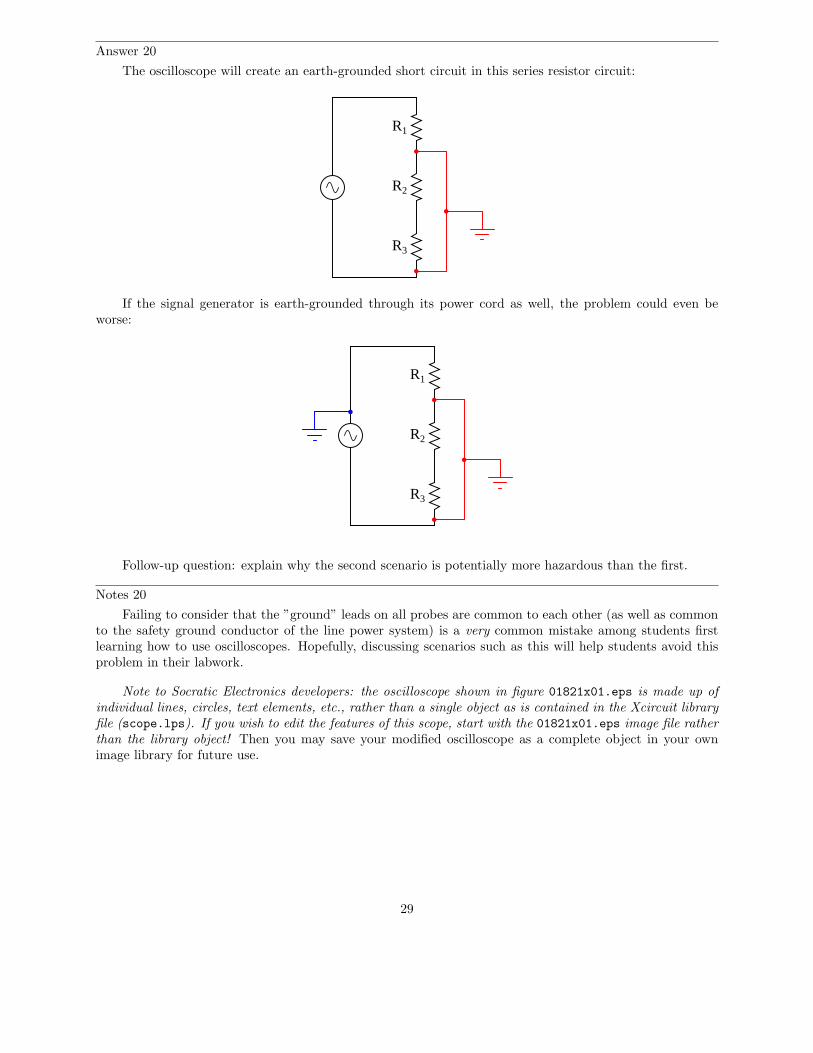
Answer 20
The oscilloscope will create an earth-grounded short circuit in this series resistor circuit:
R1
R2
R3
If the signal generator is earth-grounded through its power cord as well, the problem could even beworse:
R1
R2
R3
Follow-up question: explain why the second scenario is potentially more hazardous than the first.
Notes 20
Failing to consider that the ”ground” leads on all probes are common to each other (as well as commonto the safety ground conductor of the line power system) is a very common mistake among students firstlearning how to use oscilloscopes. Hopefully, discussing scenarios such as this will help students avoid thisproblem in their labwork.
Note to Socratic Electronics developers: the oscilloscope shown in figure 01821x01.eps is made up ofindividual lines, circles, text elements, etc., rather than a single object as is contained in the Xcircuit libraryfile (scope.lps). If you wish to edit the features of this scope, start with the 01821x01.eps image file ratherthan the library object! Then you may save your modified oscilloscope as a complete object in your ownimage library for future use.
29

Question 21
How is it possible to assign a fixed value of voltage or current (such as ”120 volts”) to an AC electricalquantity that is constantly changing, crossing 0 volts, and reversing polarity?
file 00051
Answer 21
We may express quantities of AC voltage and current in terms of peak, peak-to-peak, average, or RMS.
Notes 21
Before you discuss ”RMS” values with your students, it is important to cover the basic idea of how toassign fixed values to quantities that change over time. Since AC waveforms are cyclic (repeating), this isnot as difficult to do as one might think.
30
Question 22
Suppose a DC power source with a voltage of 50 volts is connected to a 10 Ω load. How much powerwill this load dissipate?
Now suppose the same 10 Ω load is connected to a sinusoidal AC power source with a peak voltage of 50volts. Will the load dissipate the same amount of power, more power, or less power? Explain your answer.
file 00401
Answer 22
50 volts DC applied to a 10 Ω load will dissipate 250 watts of power. 50 volts (peak, sinusoidal) ACwill deliver less than 250 watts to the same load.
Notes 22
There are many analogies to explain this discrepancy between the two ”50 volt” sources. One is tocompare the physical effort of a person pushing with a constant force of 50 pounds, versus someone whopushes intermittently with only a peak force of 50 pounds.
31
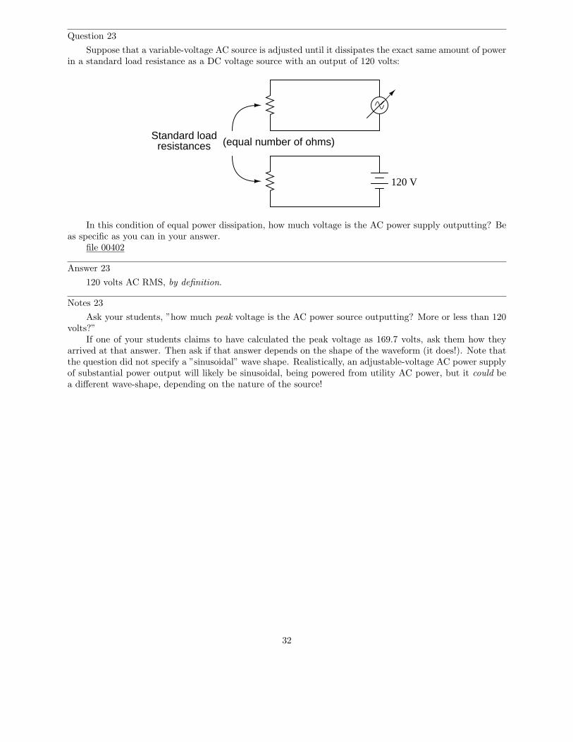
Question 23
Suppose that a variable-voltage AC source is adjusted until it dissipates the exact same amount of powerin a standard load resistance as a DC voltage source with an output of 120 volts:
Standard loadresistances (equal number of ohms)
120 V
In this condition of equal power dissipation, how much voltage is the AC power supply outputting? Beas specific as you can in your answer.
file 00402
Answer 23
120 volts AC RMS, by definition.
Notes 23
Ask your students, ”how much peak voltage is the AC power source outputting? More or less than 120volts?”
If one of your students claims to have calculated the peak voltage as 169.7 volts, ask them how theyarrived at that answer. Then ask if that answer depends on the shape of the waveform (it does!). Note thatthe question did not specify a ”sinusoidal” wave shape. Realistically, an adjustable-voltage AC power supplyof substantial power output will likely be sinusoidal, being powered from utility AC power, but it could bea different wave-shape, depending on the nature of the source!
32
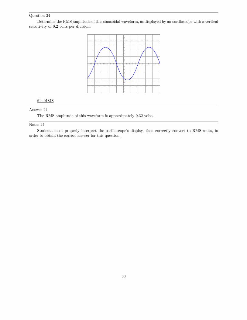
Question 24
Determine the RMS amplitude of this sinusoidal waveform, as displayed by an oscilloscope with a verticalsensitivity of 0.2 volts per division:
file 01818
Answer 24
The RMS amplitude of this waveform is approximately 0.32 volts.
Notes 24
Students must properly interpret the oscilloscope’s display, then correctly convert to RMS units, inorder to obtain the correct answer for this question.
33
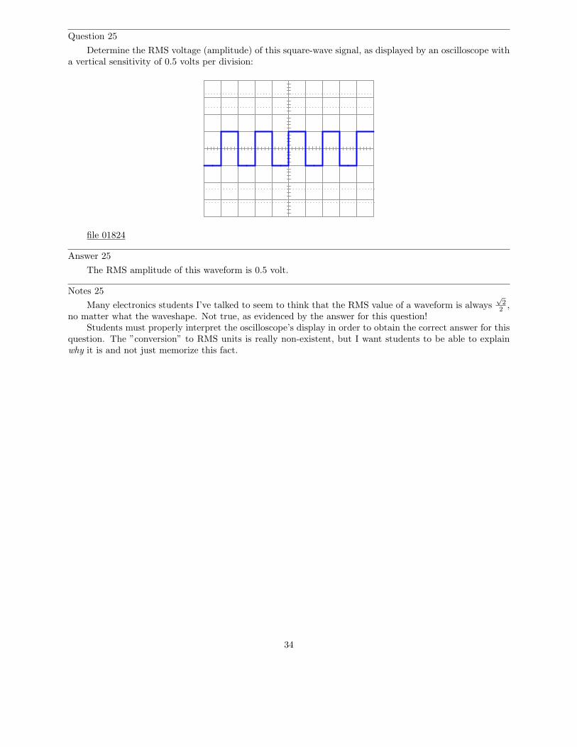
Question 25
Determine the RMS voltage (amplitude) of this square-wave signal, as displayed by an oscilloscope witha vertical sensitivity of 0.5 volts per division:
file 01824
Answer 25
The RMS amplitude of this waveform is 0.5 volt.
Notes 25
Many electronics students I’ve talked to seem to think that the RMS value of a waveform is always√
2
2,
no matter what the waveshape. Not true, as evidenced by the answer for this question!Students must properly interpret the oscilloscope’s display in order to obtain the correct answer for this
question. The ”conversion” to RMS units is really non-existent, but I want students to be able to explainwhy it is and not just memorize this fact.
34

Question 26
Suppose two voltmeters are connected to source of ”mains” AC power in a residence, one meter is analog(D’Arsonval PMMC meter movement) while the other is true-RMS digital. They both register 117 voltswhile connected to this AC source.
Suddenly, a large electrical load is turned on somewhere in the system. This load both reduces the mainsvoltage and slightly distorts the shape of the waveform. The overall effect of this is average AC voltage hasdecreased by 4.5% from where it was, while RMS AC voltage has decreased by 6% from where it was. Howmuch voltage does each voltmeter register now?
file 02790
Answer 26
Analog voltmeter now registers: 111.7 volts
True-RMS digital voltmeter now registers: 110 volts
Notes 26
Students sometimes have difficulty grasping the significance of PMMC meter movements being ”average-responding” rather than RMS-responding. Hopefully, the answer to this question will help illuminate thissubject more.
35
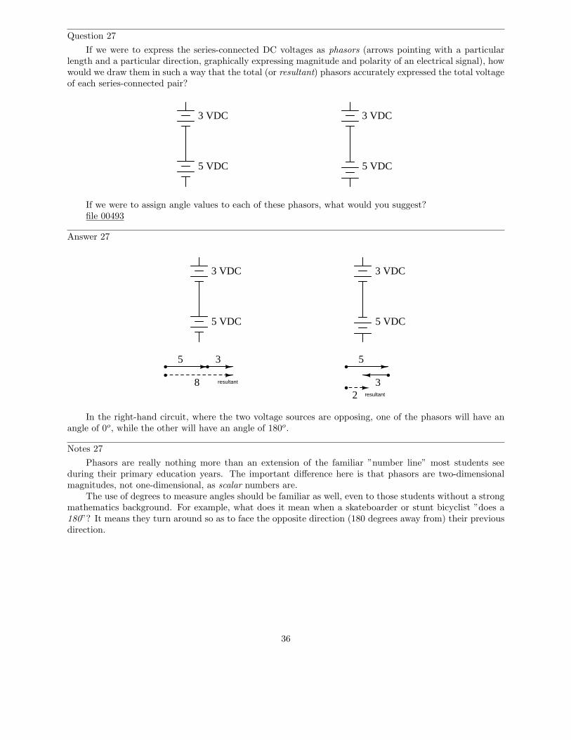
Question 27
If we were to express the series-connected DC voltages as phasors (arrows pointing with a particularlength and a particular direction, graphically expressing magnitude and polarity of an electrical signal), howwould we draw them in such a way that the total (or resultant) phasors accurately expressed the total voltageof each series-connected pair?
3 VDC
5 VDC
3 VDC
5 VDC
If we were to assign angle values to each of these phasors, what would you suggest?file 00493
Answer 27
3 VDC
5 VDC
3 VDC
5 VDC
8 resultant
5 3
resultant
5
32
In the right-hand circuit, where the two voltage sources are opposing, one of the phasors will have anangle of 0o, while the other will have an angle of 180o.
Notes 27
Phasors are really nothing more than an extension of the familiar ”number line” most students seeduring their primary education years. The important difference here is that phasors are two-dimensionalmagnitudes, not one-dimensional, as scalar numbers are.
The use of degrees to measure angles should be familiar as well, even to those students without a strongmathematics background. For example, what does it mean when a skateboarder or stunt bicyclist ”does a180”? It means they turn around so as to face the opposite direction (180 degrees away from) their previousdirection.
36
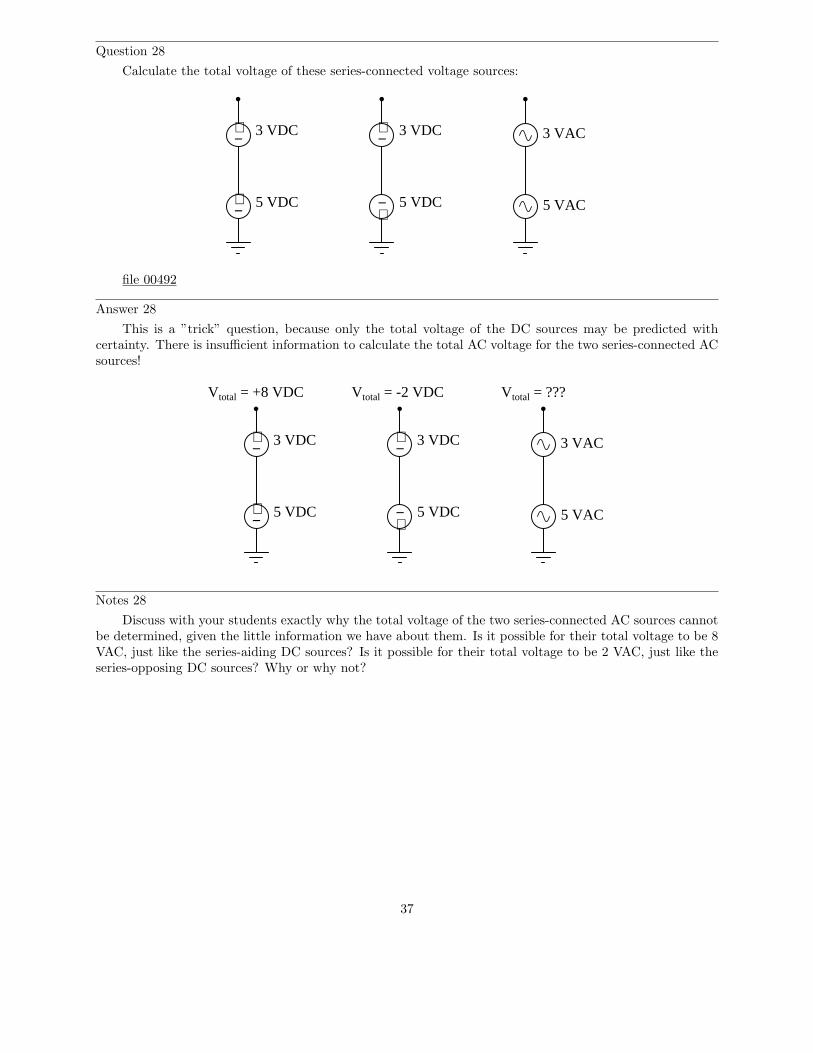
Question 28
Calculate the total voltage of these series-connected voltage sources:
3 VAC
5 VAC
3 VDC
5 VDC
3 VDC
5 VDC
+−
+−
+−
+−
file 00492
Answer 28
This is a ”trick” question, because only the total voltage of the DC sources may be predicted withcertainty. There is insufficient information to calculate the total AC voltage for the two series-connected ACsources!
3 VAC
5 VAC
3 VDC
5 VDC
3 VDC
5 VDC
+−
+−
+−
+−
Vtotal = +8 VDC Vtotal = -2 VDC Vtotal = ???
Notes 28
Discuss with your students exactly why the total voltage of the two series-connected AC sources cannotbe determined, given the little information we have about them. Is it possible for their total voltage to be 8VAC, just like the series-aiding DC sources? Is it possible for their total voltage to be 2 VAC, just like theseries-opposing DC sources? Why or why not?
37
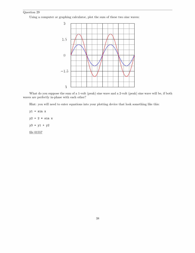
Question 29
Using a computer or graphing calculator, plot the sum of these two sine waves:
31:501:53
What do you suppose the sum of a 1-volt (peak) sine wave and a 2-volt (peak) sine wave will be, if bothwaves are perfectly in-phase with each other?
Hint: you will need to enter equations into your plotting device that look something like this:
y1 = sin x
y2 = 2 * sin x
y3 = y1 + y2
file 01557
38
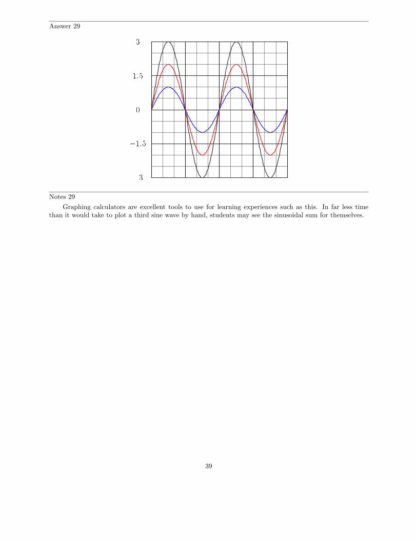
Answer 29
31:501:53
Notes 29
Graphing calculators are excellent tools to use for learning experiences such as this. In far less timethan it would take to plot a third sine wave by hand, students may see the sinusoidal sum for themselves.
39
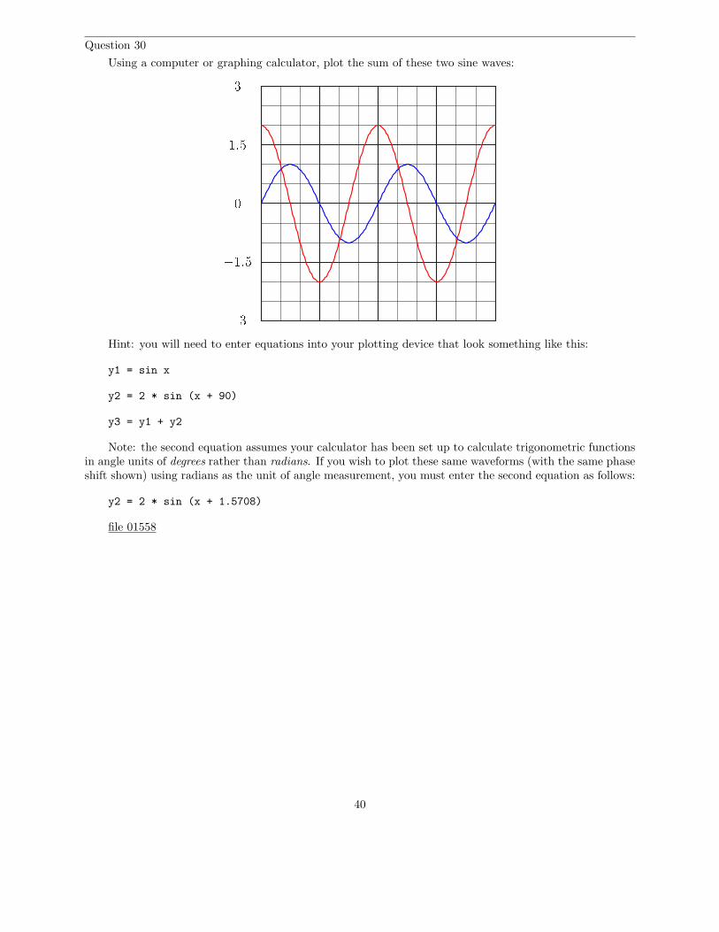
Question 30
Using a computer or graphing calculator, plot the sum of these two sine waves:
31:501:53
Hint: you will need to enter equations into your plotting device that look something like this:
y1 = sin x
y2 = 2 * sin (x + 90)
y3 = y1 + y2
Note: the second equation assumes your calculator has been set up to calculate trigonometric functionsin angle units of degrees rather than radians. If you wish to plot these same waveforms (with the same phaseshift shown) using radians as the unit of angle measurement, you must enter the second equation as follows:
y2 = 2 * sin (x + 1.5708)
file 01558
40
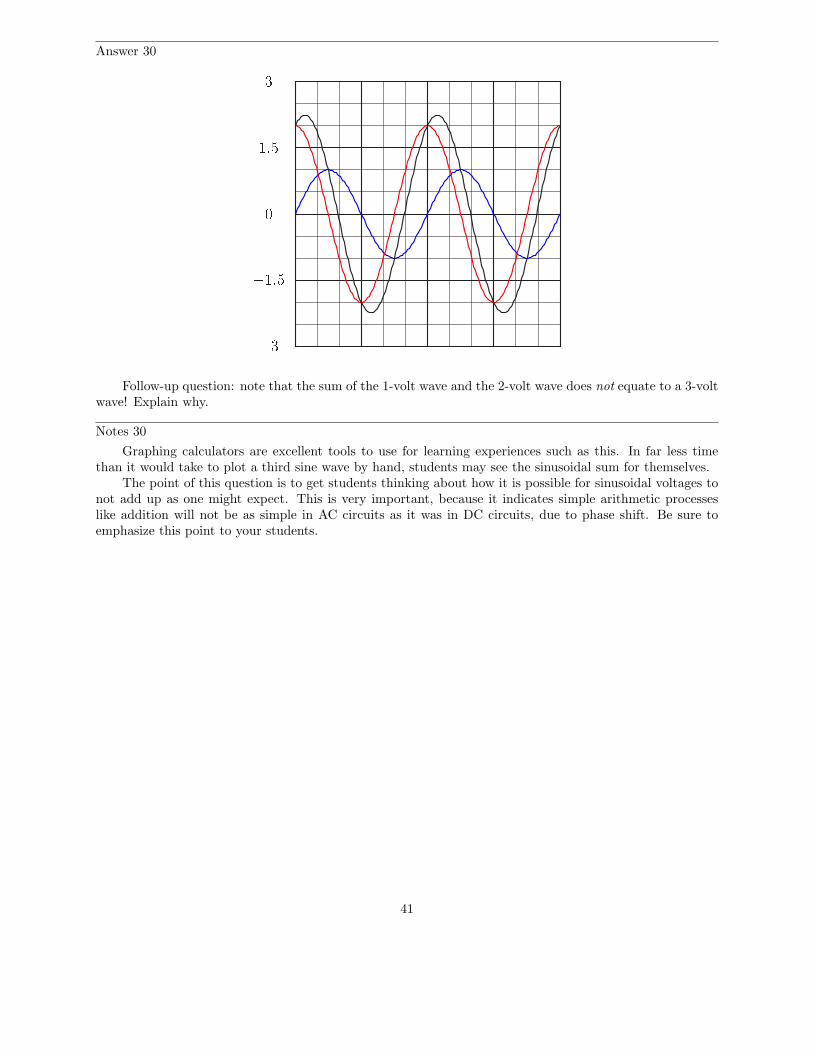
Answer 30
31:501:53
Follow-up question: note that the sum of the 1-volt wave and the 2-volt wave does not equate to a 3-voltwave! Explain why.
Notes 30
Graphing calculators are excellent tools to use for learning experiences such as this. In far less timethan it would take to plot a third sine wave by hand, students may see the sinusoidal sum for themselves.
The point of this question is to get students thinking about how it is possible for sinusoidal voltages tonot add up as one might expect. This is very important, because it indicates simple arithmetic processeslike addition will not be as simple in AC circuits as it was in DC circuits, due to phase shift. Be sure toemphasize this point to your students.
41
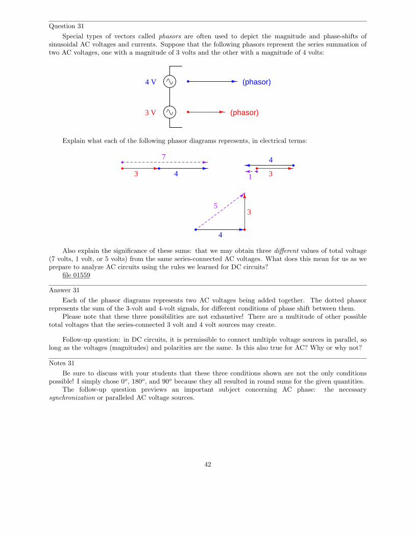
Question 31
Special types of vectors called phasors are often used to depict the magnitude and phase-shifts ofsinusoidal AC voltages and currents. Suppose that the following phasors represent the series summation oftwo AC voltages, one with a magnitude of 3 volts and the other with a magnitude of 4 volts:
3 V
4 V (phasor)
(phasor)
Explain what each of the following phasor diagrams represents, in electrical terms:
3 4 3
4
4
3
7
1
5
Also explain the significance of these sums: that we may obtain three different values of total voltage(7 volts, 1 volt, or 5 volts) from the same series-connected AC voltages. What does this mean for us as weprepare to analyze AC circuits using the rules we learned for DC circuits?
file 01559
Answer 31
Each of the phasor diagrams represents two AC voltages being added together. The dotted phasorrepresents the sum of the 3-volt and 4-volt signals, for different conditions of phase shift between them.
Please note that these three possibilities are not exhaustive! There are a multitude of other possibletotal voltages that the series-connected 3 volt and 4 volt sources may create.
Follow-up question: in DC circuits, it is permissible to connect multiple voltage sources in parallel, solong as the voltages (magnitudes) and polarities are the same. Is this also true for AC? Why or why not?
Notes 31
Be sure to discuss with your students that these three conditions shown are not the only conditionspossible! I simply chose 0o, 180o, and 90o because they all resulted in round sums for the given quantities.
The follow-up question previews an important subject concerning AC phase: the necessarysynchronization or paralleled AC voltage sources.
42
Question 32
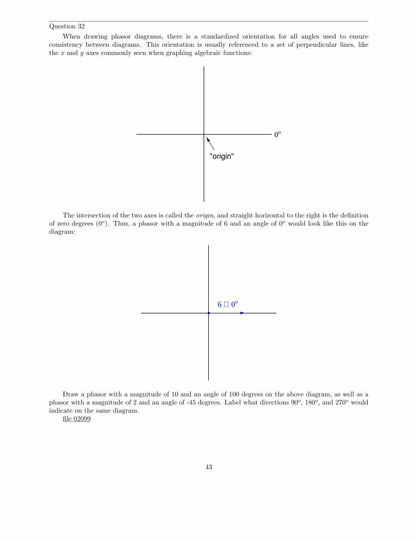
When drawing phasor diagrams, there is a standardized orientation for all angles used to ensureconsistency between diagrams. This orientation is usually referenced to a set of perpendicular lines, likethe x and y axes commonly seen when graphing algebraic functions:
0o
"origin"
The intersection of the two axes is called the origin, and straight horizontal to the right is the definitionof zero degrees (0o). Thus, a phasor with a magnitude of 6 and an angle of 0o would look like this on thediagram:
6 ∠ 0o
Draw a phasor with a magnitude of 10 and an angle of 100 degrees on the above diagram, as well as aphasor with a magnitude of 2 and an angle of -45 degrees. Label what directions 90o, 180o, and 270o wouldindicate on the same diagram.
file 02099
43
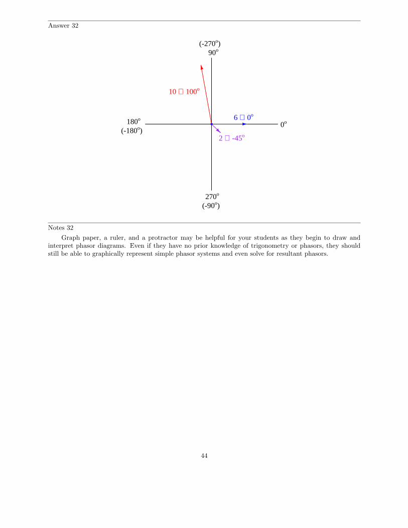
Answer 32
6 ∠ 0o
10 ∠ 100o
2 ∠ -45o
0o
90o
180o
270o
(-90o)
(-270o)
(-180o)
Notes 32
Graph paper, a ruler, and a protractor may be helpful for your students as they begin to draw andinterpret phasor diagrams. Even if they have no prior knowledge of trigonometry or phasors, they shouldstill be able to graphically represent simple phasor systems and even solve for resultant phasors.
44
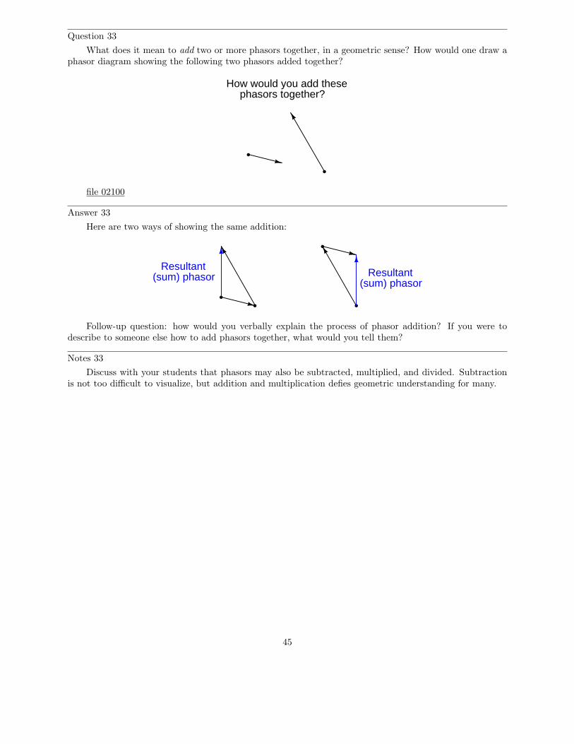
Question 33
What does it mean to add two or more phasors together, in a geometric sense? How would one draw aphasor diagram showing the following two phasors added together?
How would you add thesephasors together?
file 02100
Answer 33
Here are two ways of showing the same addition:
Resultant(sum) phasor Resultant
(sum) phasor
Follow-up question: how would you verbally explain the process of phasor addition? If you were todescribe to someone else how to add phasors together, what would you tell them?
Notes 33
Discuss with your students that phasors may also be subtracted, multiplied, and divided. Subtractionis not too difficult to visualize, but addition and multiplication defies geometric understanding for many.
45
Question 34
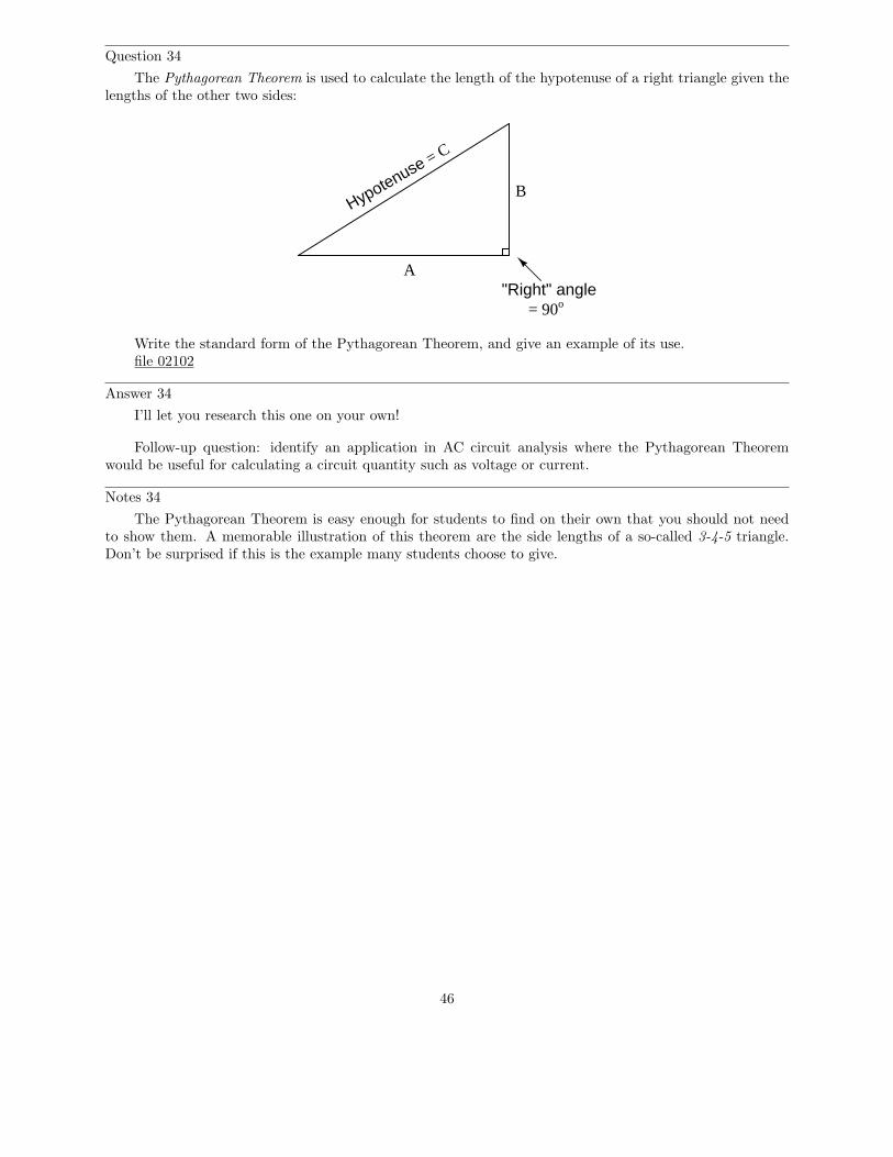
The Pythagorean Theorem is used to calculate the length of the hypotenuse of a right triangle given thelengths of the other two sides:
Hypotenuse = C
A
B
"Right" angle= 90o
Write the standard form of the Pythagorean Theorem, and give an example of its use.file 02102
Answer 34
I’ll let you research this one on your own!
Follow-up question: identify an application in AC circuit analysis where the Pythagorean Theoremwould be useful for calculating a circuit quantity such as voltage or current.
Notes 34
The Pythagorean Theorem is easy enough for students to find on their own that you should not needto show them. A memorable illustration of this theorem are the side lengths of a so-called 3-4-5 triangle.Don’t be surprised if this is the example many students choose to give.
46
Question 35
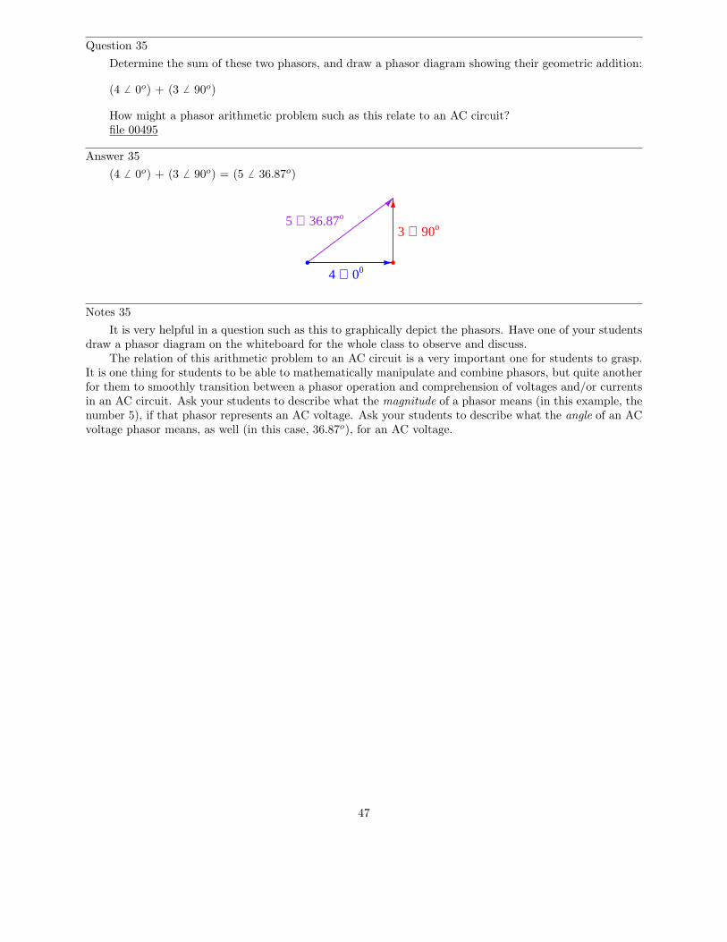
Determine the sum of these two phasors, and draw a phasor diagram showing their geometric addition:
(4 6 0o) + (3 6 90o)
How might a phasor arithmetic problem such as this relate to an AC circuit?file 00495
Answer 35
(4 6 0o) + (3 6 90o) = (5 6 36.87o)
4 ∠ 00
3 ∠ 90o5 ∠ 36.87o
Notes 35
It is very helpful in a question such as this to graphically depict the phasors. Have one of your studentsdraw a phasor diagram on the whiteboard for the whole class to observe and discuss.
The relation of this arithmetic problem to an AC circuit is a very important one for students to grasp.It is one thing for students to be able to mathematically manipulate and combine phasors, but quite anotherfor them to smoothly transition between a phasor operation and comprehension of voltages and/or currentsin an AC circuit. Ask your students to describe what the magnitude of a phasor means (in this example, thenumber 5), if that phasor represents an AC voltage. Ask your students to describe what the angle of an ACvoltage phasor means, as well (in this case, 36.87o), for an AC voltage.
47

Question 36
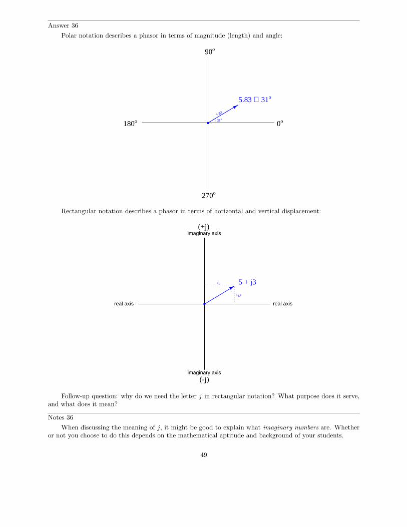
Phasors may be symbolically described in two different ways: polar notation and rectangular notation.Explain what each of these notations means, and why either one may adequately describe a phasor.
file 02101
48
Answer 36
Polar notation describes a phasor in terms of magnitude (length) and angle:
0o
5.83 ∠ 31o
5.83
31o
90o
180o
270o
Rectangular notation describes a phasor in terms of horizontal and vertical displacement:
real axisreal axis
imaginary axis
imaginary axis
(+j)
(-j)
+j3
+5 5 + j3
Follow-up question: why do we need the letter j in rectangular notation? What purpose does it serve,and what does it mean?
Notes 36
When discussing the meaning of j, it might be good to explain what imaginary numbers are. Whetheror not you choose to do this depends on the mathematical aptitude and background of your students.
49
Question 37
These two phasors are written in a form known as polar notation. Re-write them in rectangular notation:
4 6 0o =
3 6 90o =
file 00497
Answer 37
These two phasors, written in rectangular notation, would be 4 + j0 and 0 + j3, respectively, althougha mathematician would probably write them as 4 + i0 and 0 + i3, respectively.
Challenge question: what does the lower-case j or i represent, in mathematical terms?
Notes 37
Discuss with your students the two notations commonly used with phasors: polar and rectangular form.They are merely two different ways of ”saying” the same thing. A helpful ”prop” for this discussion is thecomplex number plane (as opposed to a number line – a one-dimensional field), showing the ”real” and”imaginary” axes, in addition to standard angles (right = 0o, left = 180o, up = 90o, down = 270o). Yourstudents should be familiar with this from their research, so have one of them draw the number plane on thewhiteboard for all to view.
The challenge question regards the origin of complex numbers, beginning with the distinction of”imaginary” numbers as being a separate set of quantities from ”real” numbers. Electrical engineers, ofcourse, avoid using the lower-case letter i to denote ”imaginary” because it would be so easily be confusedwith the standard notation for instantaneous current i.
50
Question 38
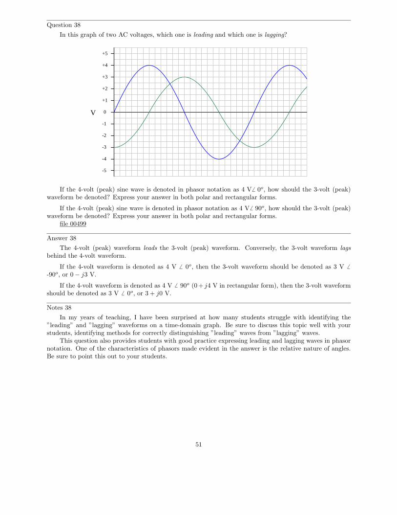
In this graph of two AC voltages, which one is leading and which one is lagging?
0
+1
+2
+3
+4
+5
-1
-2
-3
-4
-5
V
If the 4-volt (peak) sine wave is denoted in phasor notation as 4 V6 0o, how should the 3-volt (peak)waveform be denoted? Express your answer in both polar and rectangular forms.
If the 4-volt (peak) sine wave is denoted in phasor notation as 4 V6 90o, how should the 3-volt (peak)waveform be denoted? Express your answer in both polar and rectangular forms.
file 00499
Answer 38
The 4-volt (peak) waveform leads the 3-volt (peak) waveform. Conversely, the 3-volt waveform lagsbehind the 4-volt waveform.
If the 4-volt waveform is denoted as 4 V 6 0o, then the 3-volt waveform should be denoted as 3 V 6
-90o, or 0 − j3 V.
If the 4-volt waveform is denoted as 4 V 6 90o (0+ j4 V in rectangular form), then the 3-volt waveformshould be denoted as 3 V 6 0o, or 3 + j0 V.
Notes 38
In my years of teaching, I have been surprised at how many students struggle with identifying the”leading” and ”lagging” waveforms on a time-domain graph. Be sure to discuss this topic well with yourstudents, identifying methods for correctly distinguishing ”leading” waves from ”lagging” waves.
This question also provides students with good practice expressing leading and lagging waves in phasornotation. One of the characteristics of phasors made evident in the answer is the relative nature of angles.Be sure to point this out to your students.
51
Question 39
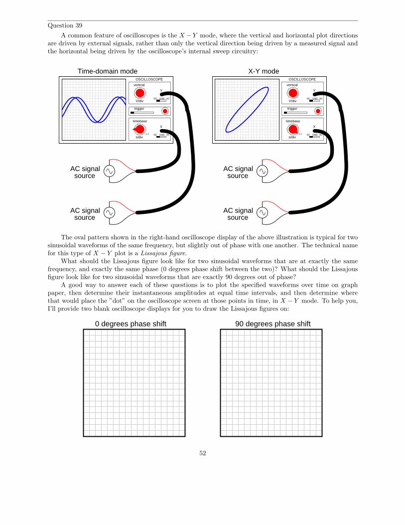
A common feature of oscilloscopes is the X − Y mode, where the vertical and horizontal plot directionsare driven by external signals, rather than only the vertical direction being driven by a measured signal andthe horizontal being driven by the oscilloscope’s internal sweep circuitry:
trigger
timebase
s/divDC GND AC
X
GNDDCV/div
vertical
OSCILLOSCOPE
Y
AC
X-Y
trigger
timebase
s/divDC GND AC
X
GNDDCV/div
vertical
OSCILLOSCOPE
Y
AC
AC signalsource
X-Y
X-Y mode
AC signalsource
AC signalsource
AC signalsource
Time-domain mode
The oval pattern shown in the right-hand oscilloscope display of the above illustration is typical for twosinusoidal waveforms of the same frequency, but slightly out of phase with one another. The technical namefor this type of X − Y plot is a Lissajous figure.
What should the Lissajous figure look like for two sinusoidal waveforms that are at exactly the samefrequency, and exactly the same phase (0 degrees phase shift between the two)? What should the Lissajousfigure look like for two sinusoidal waveforms that are exactly 90 degrees out of phase?
A good way to answer each of these questions is to plot the specified waveforms over time on graphpaper, then determine their instantaneous amplitudes at equal time intervals, and then determine wherethat would place the ”dot” on the oscilloscope screen at those points in time, in X − Y mode. To help you,I’ll provide two blank oscilloscope displays for you to draw the Lissajous figures on:
0 degrees phase shift 90 degrees phase shift
52
file 01480
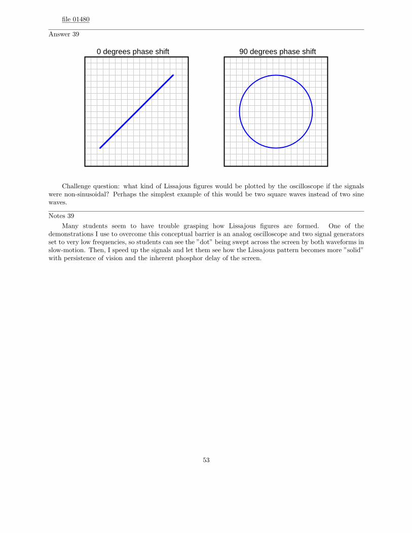
Answer 39
0 degrees phase shift 90 degrees phase shift
Challenge question: what kind of Lissajous figures would be plotted by the oscilloscope if the signalswere non-sinusoidal? Perhaps the simplest example of this would be two square waves instead of two sinewaves.
Notes 39
Many students seem to have trouble grasping how Lissajous figures are formed. One of thedemonstrations I use to overcome this conceptual barrier is an analog oscilloscope and two signal generatorsset to very low frequencies, so students can see the ”dot” being swept across the screen by both waveforms inslow-motion. Then, I speed up the signals and let them see how the Lissajous pattern becomes more ”solid”with persistence of vision and the inherent phosphor delay of the screen.
53
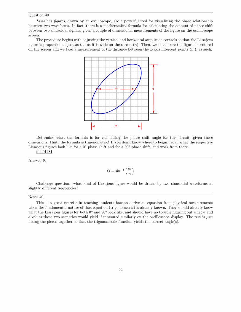
Question 40
Lissajous figures, drawn by an oscilloscope, are a powerful tool for visualizing the phase relationshipbetween two waveforms. In fact, there is a mathematical formula for calculating the amount of phase shiftbetween two sinusoidal signals, given a couple of dimensional measurements of the figure on the oscilloscopescreen.
The procedure begins with adjusting the vertical and horizontal amplitude controls so that the Lissajousfigure is proportional: just as tall as it is wide on the screen (n). Then, we make sure the figure is centeredon the screen and we take a measurement of the distance between the x-axis intercept points (m), as such:
m n
n
Determine what the formula is for calculating the phase shift angle for this circuit, given thesedimensions. Hint: the formula is trigonometric! If you don’t know where to begin, recall what the respectiveLissajous figures look like for a 0o phase shift and for a 90o phase shift, and work from there.
file 01481
Answer 40
Θ = sin−1(m
n
)
Challenge question: what kind of Lissajous figure would be drawn by two sinusoidal waveforms atslightly different frequencies?
Notes 40
This is a great exercise in teaching students how to derive an equation from physical measurementswhen the fundamental nature of that equation (trigonometric) is already known. They should already knowwhat the Lissajous figures for both 0o and 90o look like, and should have no trouble figuring out what a andb values these two scenarios would yield if measured similarly on the oscilloscope display. The rest is justfitting the pieces together so that the trigonometric function yields the correct angle(s).
54

Question 41
As a general rule, inductors oppose change in (choose: voltage or current), and they do so by . . .(complete the sentence).
Based on this rule, determine how an inductor would react to a constant AC current that increases infrequency. Would an inductor drop more or less voltage, given a greater frequency? Explain your answer.
file 00578
Answer 41
As a general rule, inductors oppose change in current, and they do so by producing a voltage.
An inductor will drop a greater amount of AC voltage, given the same AC current, at a greater frequency.
Notes 41
This question is an exercise in qualitative thinking: relating rates of change to other variables, withoutthe use of numerical quantities. The general rule stated here is very, very important for students to master,and be able to apply to a variety of circumstances. If they learn nothing about inductors except for thisrule, they will be able to grasp the function of a great many inductor circuits.
55
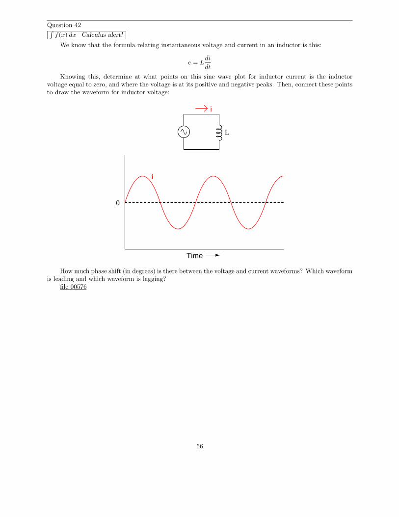
Question 42∫
f(x) dx Calculus alert!
We know that the formula relating instantaneous voltage and current in an inductor is this:
e = Ldi
dt
Knowing this, determine at what points on this sine wave plot for inductor current is the inductorvoltage equal to zero, and where the voltage is at its positive and negative peaks. Then, connect these pointsto draw the waveform for inductor voltage:
Time
0
i
i
L
How much phase shift (in degrees) is there between the voltage and current waveforms? Which waveformis leading and which waveform is lagging?
file 00576
56
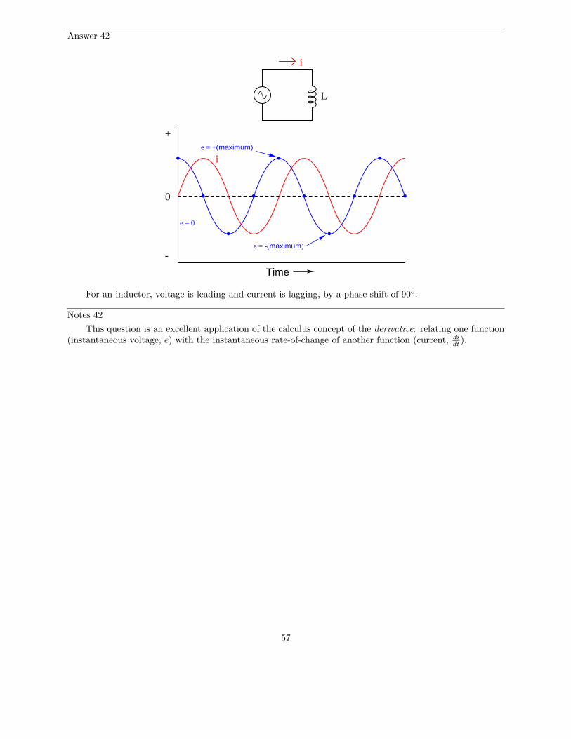
Answer 42
Time
0
i
i
L
e = 0
e = -(maximum)
e = +(maximum)
+
-
For an inductor, voltage is leading and current is lagging, by a phase shift of 90o.
Notes 42
This question is an excellent application of the calculus concept of the derivative: relating one function(instantaneous voltage, e) with the instantaneous rate-of-change of another function (current, di
dt).
57

Question 43
Does an inductor’s opposition to alternating current increase or decrease as the frequency of that currentincreases? Also, explain why we refer to this opposition of AC current in an inductor as reactance insteadof resistance.
file 00580
Answer 43
The opposition to AC current (”reactance”) of an inductor increases as frequency increases. We referto this opposition as ”reactance” rather than ”resistance” because it is non-dissipative in nature. In otherwords, reactance causes no power to leave the circuit.
Notes 43
Ask your students to define the relationship between inductor reactance and frequency as either ”directlyproportional” or ”inversely proportional”. These are two phrases used often in science and engineering todescribe whether one quantity increases or decreases as another quantity increases. Your students definitelyneed to be familiar with both these phrases, and be able to interpret and use them in their technicaldiscussions.
Also, discuss the meaning of the word ”non-dissipative” in this context. How could we prove that theopposition to current expressed by an inductor is non-dissipative? What would be the ultimate test of this?
58
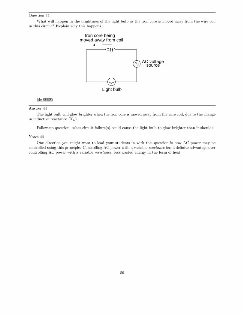
Question 44
What will happen to the brightness of the light bulb as the iron core is moved away from the wire coilin this circuit? Explain why this happens.
Light bulb
AC voltagesource
Iron core beingmoved away from coil
file 00095
Answer 44
The light bulb will glow brighter when the iron core is moved away from the wire coil, due to the changein inductive reactance (XL).
Follow-up question: what circuit failure(s) could cause the light bulb to glow brighter than it should?
Notes 44
One direction you might want to lead your students in with this question is how AC power may becontrolled using this principle. Controlling AC power with a variable reactance has a definite advantage overcontrolling AC power with a variable resistance: less wasted energy in the form of heat.
59
Question 45
An inductor rated at 4 Henrys is subjected to a sinusoidal AC voltage of 24 volts RMS, at a frequencyof 60 hertz. Write the formula for calculating inductive reactance (XL), and solve for current through theinductor.
file 00582
Answer 45
XL = 2πfL
The current through this inductor is 15.92 mA RMS.
Notes 45
I have consistently found that qualitative (greater than, less than, or equal) analysis is much moredifficult for students to perform than quantitative (punch the numbers on a calculator) analysis. Yet, I haveconsistently found on the job that people lacking qualitative skills make more ”silly” quantitative errorsbecause they cannot validate their calculations by estimation.
In light of this, I always challenge my students to qualitatively analyze formulae when they are firstintroduced to them. Ask your students to identify what will happen to one term of an equation if anotherterm were to either increase, or decrease (you choose the direction of change). Use up and down arrowsymbols if necessary to communicate these changes graphically. Your students will greatly benefit in theirconceptual understanding of applied mathematics from this kind of practice!
60

Question 46
At what frequency does a 350 mH inductor have 4.7 kΩ of reactance? Write the formula for solvingthis, in addition to calculating the frequency.
file 00586
Answer 46
f = 2.137 kHz
Notes 46
Be sure to ask your students to demonstrate the algebraic manipulation of the original formula, inproviding the answer to this question. Algebraic manipulation of equations is a very important skill to have,and it comes only by study and practice.
61

Question 47
How much inductance would an inductor have to possess in order to provide 540 Ω of reactance at afrequency of 400 Hz? Write the formula for solving this, in addition to calculating the frequency.
file 03277
Answer 47
L = 214.9 mH
Notes 47
Be sure to ask your students to demonstrate the algebraic manipulation of the original formula, inproviding the answer to this question. Algebraic manipulation of equations is a very important skill to have,and it comes only by study and practice.
62
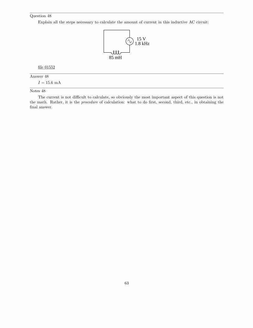
Question 48
Explain all the steps necessary to calculate the amount of current in this inductive AC circuit:
15 V1.8 kHz
85 mH
file 01552
Answer 48
I = 15.6 mA
Notes 48
The current is not difficult to calculate, so obviously the most important aspect of this question is notthe math. Rather, it is the procedure of calculation: what to do first, second, third, etc., in obtaining thefinal answer.
63
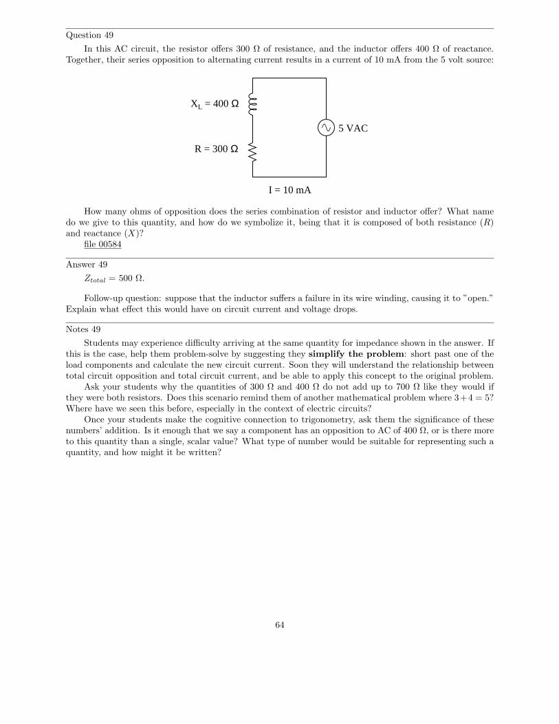
Question 49
In this AC circuit, the resistor offers 300 Ω of resistance, and the inductor offers 400 Ω of reactance.Together, their series opposition to alternating current results in a current of 10 mA from the 5 volt source:
R = 300 Ω
XL = 400 Ω
5 VAC
I = 10 mA
How many ohms of opposition does the series combination of resistor and inductor offer? What namedo we give to this quantity, and how do we symbolize it, being that it is composed of both resistance (R)and reactance (X)?
file 00584
Answer 49
Ztotal = 500 Ω.
Follow-up question: suppose that the inductor suffers a failure in its wire winding, causing it to ”open.”Explain what effect this would have on circuit current and voltage drops.
Notes 49
Students may experience difficulty arriving at the same quantity for impedance shown in the answer. Ifthis is the case, help them problem-solve by suggesting they simplify the problem: short past one of theload components and calculate the new circuit current. Soon they will understand the relationship betweentotal circuit opposition and total circuit current, and be able to apply this concept to the original problem.
Ask your students why the quantities of 300 Ω and 400 Ω do not add up to 700 Ω like they would ifthey were both resistors. Does this scenario remind them of another mathematical problem where 3+4 = 5?Where have we seen this before, especially in the context of electric circuits?
Once your students make the cognitive connection to trigonometry, ask them the significance of thesenumbers’ addition. Is it enough that we say a component has an opposition to AC of 400 Ω, or is there moreto this quantity than a single, scalar value? What type of number would be suitable for representing such aquantity, and how might it be written?
64
Question 50
While studying DC circuit theory, you learned that resistance was an expression of a component’sopposition to electric current. Then, when studying AC circuit theory, you learned that reactance wasanother type of opposition to current. Now, a third term is introduced: impedance. Like resistance andreactance, impedance is also a form of opposition to electric current.
Explain the difference between these three quantities (resistance, reactance, and impedance) using yourown words.
file 01567
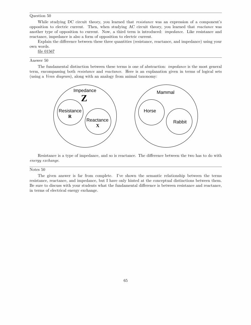
Answer 50
The fundamental distinction between these terms is one of abstraction: impedance is the most generalterm, encompassing both resistance and reactance. Here is an explanation given in terms of logical sets(using a Venn diagram), along with an analogy from animal taxonomy:
Impedance
Resistance
Reactance
Mammal
Horse
RabbitR
X
Z
Resistance is a type of impedance, and so is reactance. The difference between the two has to do withenergy exchange.
Notes 50
The given answer is far from complete. I’ve shown the semantic relationship between the termsresistance, reactance, and impedance, but I have only hinted at the conceptual distinctions between them.Be sure to discuss with your students what the fundamental difference is between resistance and reactance,in terms of electrical energy exchange.
65
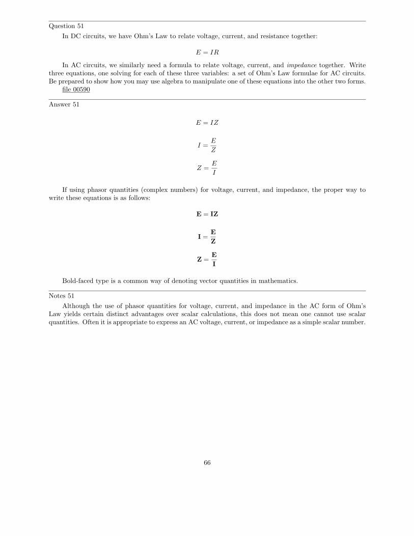
Question 51
In DC circuits, we have Ohm’s Law to relate voltage, current, and resistance together:
E = IR
In AC circuits, we similarly need a formula to relate voltage, current, and impedance together. Writethree equations, one solving for each of these three variables: a set of Ohm’s Law formulae for AC circuits.Be prepared to show how you may use algebra to manipulate one of these equations into the other two forms.
file 00590
Answer 51
E = IZ
I =E
Z
Z =E
I
If using phasor quantities (complex numbers) for voltage, current, and impedance, the proper way towrite these equations is as follows:
E = IZ
I =E
Z
Z =E
I
Bold-faced type is a common way of denoting vector quantities in mathematics.
Notes 51
Although the use of phasor quantities for voltage, current, and impedance in the AC form of Ohm’sLaw yields certain distinct advantages over scalar calculations, this does not mean one cannot use scalarquantities. Often it is appropriate to express an AC voltage, current, or impedance as a simple scalar number.
66

Question 52
It is often necessary to represent AC circuit quantities as complex numbers rather than as scalar numbers,because both magnitude and phase angle are necessary to consider in certain calculations.
When representing AC voltages and currents in polar form, the angle given refers to the phase shiftbetween the given voltage or current, and a ”reference” voltage or current at the same frequency somewhereelse in the circuit. So, a voltage of 3.5 V6 − 45o means a voltage of 3.5 volts magnitude, phase-shifted 45degrees behind (lagging) the reference voltage (or current), which is defined to be at an angle of 0 degrees.
But what about impedance (Z)? Does impedance have a phase angle, too, or is it a simple scalar numberlike resistance or reactance?
Calculate the amount of current that would go through a 100 mH inductor with 36 volts RMS appliedto it at a frequency of 400 Hz. Then, based on Ohm’s Law for AC circuits and what you know of the phaserelationship between voltage and current for an inductor, calculate the impedance of this inductor in polarform. Does a definite angle emerge from this calculation for the inductor’s impedance? Explain why or whynot.
file 00588
Answer 52
ZL = 251.33 Ω 6 90o
Notes 52
This is a challenging question, because it asks the student to defend the application of phase angles to atype of quantity that does not really possess a wave-shape like AC voltages and currents do. Conceptually,this is difficult to grasp. However, the answer is quite clear through the Ohm’s Law calculation (Z = E
I).
Although it is natural to assign a phase angle of 0o to the 36 volt supply, making it the referencewaveform, this is not actually necessary. Work through this calculation with your students, assuming differentangles for the voltage in each instance. You should find that the impedance computes to be the same exactquantity every time.
67
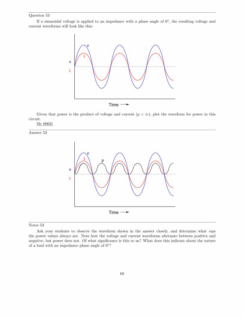
Question 53
If a sinusoidal voltage is applied to an impedance with a phase angle of 0o, the resulting voltage andcurrent waveforms will look like this:
Time
e
i
e
i
Given that power is the product of voltage and current (p = ie), plot the waveform for power in thiscircuit.
file 00631
Answer 53
Time
e
i
ei p
Notes 53
Ask your students to observe the waveform shown in the answer closely, and determine what signthe power values always are. Note how the voltage and current waveforms alternate between positive andnegative, but power does not. Of what significance is this to us? What does this indicate about the natureof a load with an impedance phase angle of 0o?
68
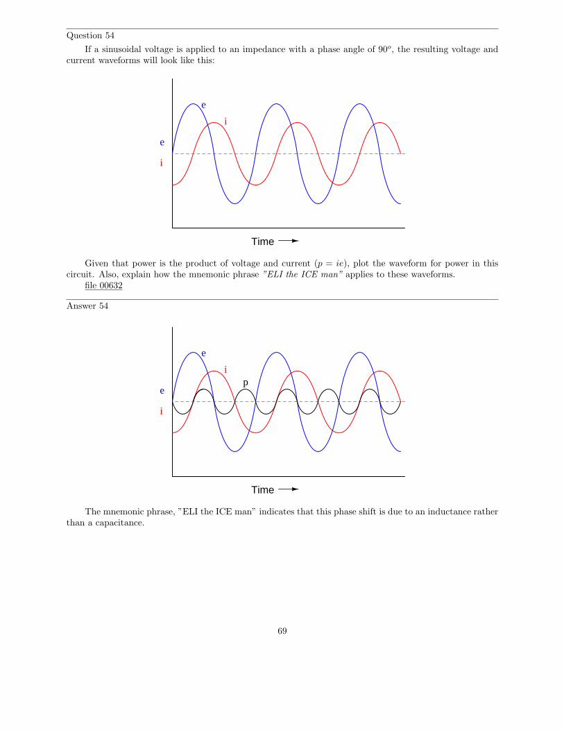
Question 54
If a sinusoidal voltage is applied to an impedance with a phase angle of 90o, the resulting voltage andcurrent waveforms will look like this:
Time
e
i
e
i
Given that power is the product of voltage and current (p = ie), plot the waveform for power in thiscircuit. Also, explain how the mnemonic phrase ”ELI the ICE man” applies to these waveforms.
file 00632
Answer 54
Time
e
i
e
ip
The mnemonic phrase, ”ELI the ICE man” indicates that this phase shift is due to an inductance ratherthan a capacitance.
69

Notes 54
Ask your students to observe the waveform shown in the answer closely, and determine what sign thepower values are. Note how the power waveform alternates between positive and negative values, just as thevoltage and current waveforms do. Ask your students to explain what negative power could possibly mean.
Of what significance is this to us? What does this indicate about the nature of a load with an impedancephase angle of 90o?
The phrase, ”ELI the ICE man” has been used be generations of technicians to remember the phaserelationships between voltage and current for inductors and capacitors, respectively. One area of trouble I’venoted with students, though, is being able to interpret which waveform is leading and which one is lagging,from a time-domain plot such as this.
70
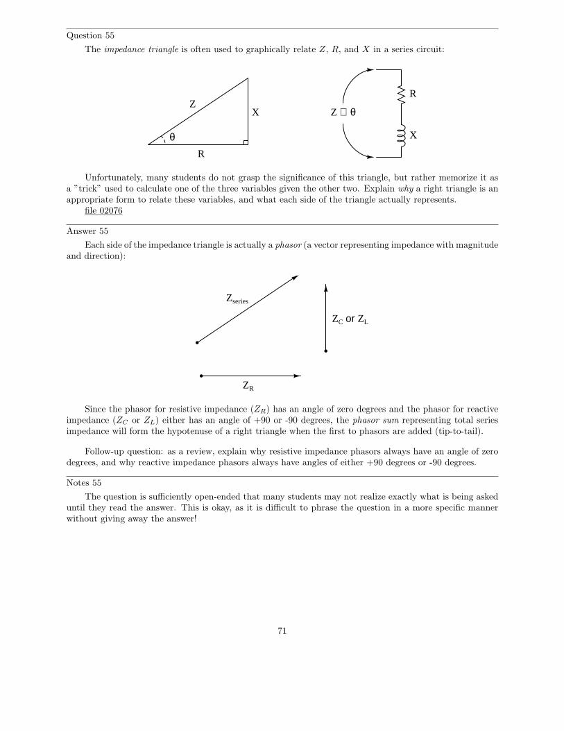
Question 55
The impedance triangle is often used to graphically relate Z, R, and X in a series circuit:
R
XZ
θ X
R
Z ∠ θ
Unfortunately, many students do not grasp the significance of this triangle, but rather memorize it asa ”trick” used to calculate one of the three variables given the other two. Explain why a right triangle is anappropriate form to relate these variables, and what each side of the triangle actually represents.
file 02076
Answer 55
Each side of the impedance triangle is actually a phasor (a vector representing impedance with magnitudeand direction):
ZR
ZC or ZL
Zseries
Since the phasor for resistive impedance (ZR) has an angle of zero degrees and the phasor for reactiveimpedance (ZC or ZL) either has an angle of +90 or -90 degrees, the phasor sum representing total seriesimpedance will form the hypotenuse of a right triangle when the first to phasors are added (tip-to-tail).
Follow-up question: as a review, explain why resistive impedance phasors always have an angle of zerodegrees, and why reactive impedance phasors always have angles of either +90 degrees or -90 degrees.
Notes 55
The question is sufficiently open-ended that many students may not realize exactly what is being askeduntil they read the answer. This is okay, as it is difficult to phrase the question in a more specific mannerwithout giving away the answer!
71
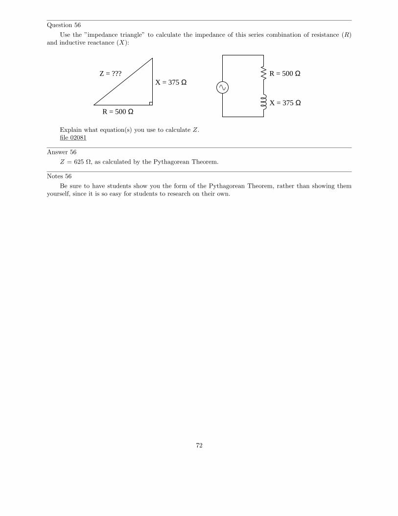
Question 56
Use the ”impedance triangle” to calculate the impedance of this series combination of resistance (R)and inductive reactance (X):
R = 500 Ω
X = 375 ΩR = 500 Ω
X = 375 ΩZ = ???
Explain what equation(s) you use to calculate Z.file 02081
Answer 56
Z = 625 Ω, as calculated by the Pythagorean Theorem.
Notes 56
Be sure to have students show you the form of the Pythagorean Theorem, rather than showing themyourself, since it is so easy for students to research on their own.
72
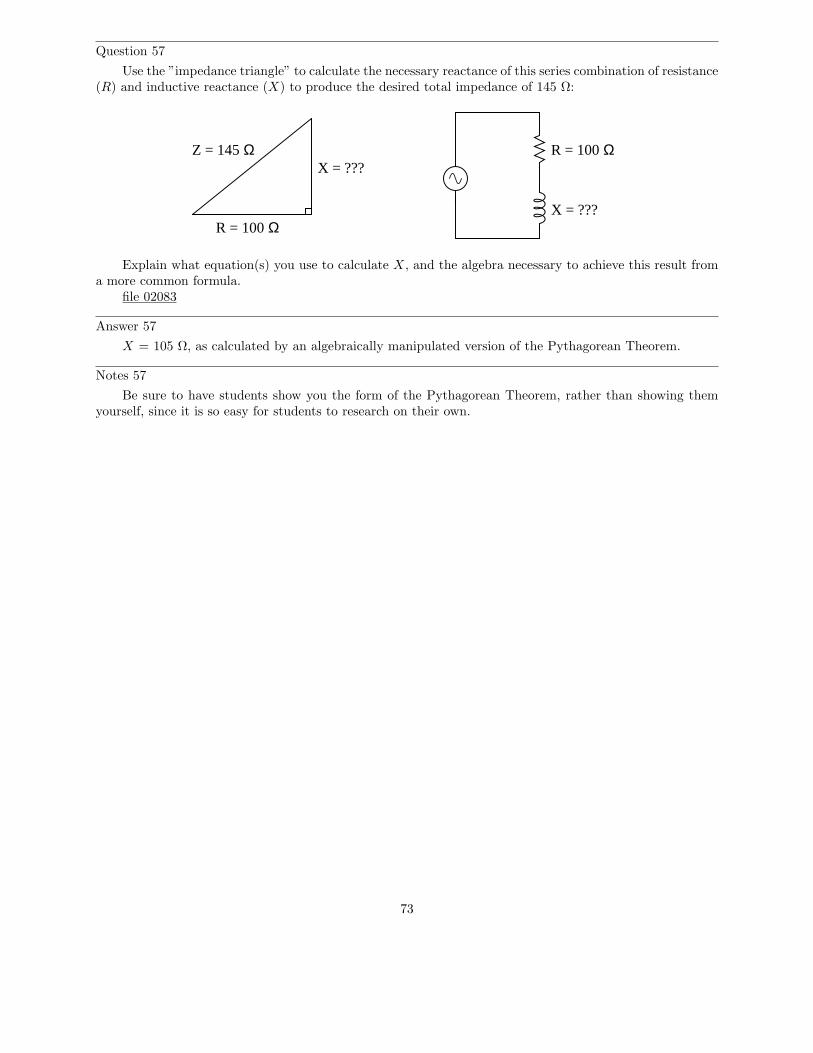
Question 57
Use the ”impedance triangle” to calculate the necessary reactance of this series combination of resistance(R) and inductive reactance (X) to produce the desired total impedance of 145 Ω:
R = 100 Ω
R = 100 ΩX = ???
Z = 145 ΩX = ???
Explain what equation(s) you use to calculate X, and the algebra necessary to achieve this result froma more common formula.
file 02083
Answer 57
X = 105 Ω, as calculated by an algebraically manipulated version of the Pythagorean Theorem.
Notes 57
Be sure to have students show you the form of the Pythagorean Theorem, rather than showing themyourself, since it is so easy for students to research on their own.
73
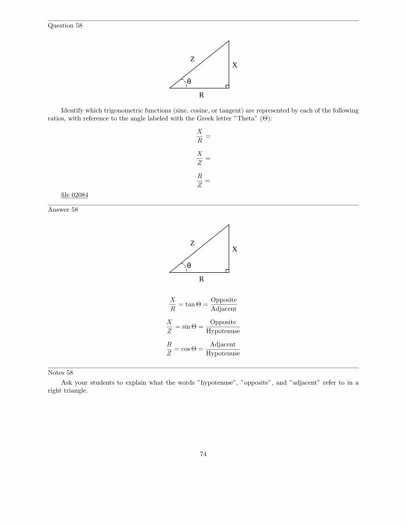
Question 58
Z
R
X
θ
Identify which trigonometric functions (sine, cosine, or tangent) are represented by each of the followingratios, with reference to the angle labeled with the Greek letter ”Theta” (Θ):
X
R=
X
Z=
R
Z=
file 02084
Answer 58
Z
R
X
θ
X
R= tan Θ =
Opposite
Adjacent
X
Z= sinΘ =
Opposite
Hypotenuse
R
Z= cos Θ =
Adjacent
Hypotenuse
Notes 58
Ask your students to explain what the words ”hypotenuse”, ”opposite”, and ”adjacent” refer to in aright triangle.
74
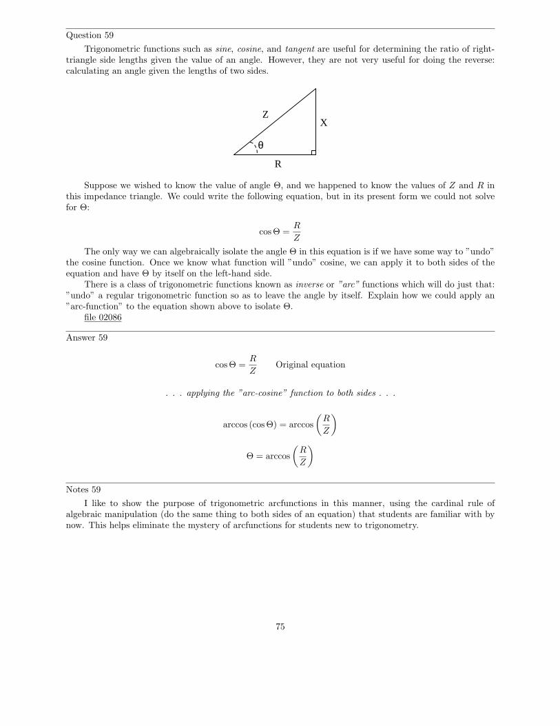
Question 59
Trigonometric functions such as sine, cosine, and tangent are useful for determining the ratio of right-triangle side lengths given the value of an angle. However, they are not very useful for doing the reverse:calculating an angle given the lengths of two sides.
Z
R
X
θ
Suppose we wished to know the value of angle Θ, and we happened to know the values of Z and R inthis impedance triangle. We could write the following equation, but in its present form we could not solvefor Θ:
cos Θ =R
Z
The only way we can algebraically isolate the angle Θ in this equation is if we have some way to ”undo”the cosine function. Once we know what function will ”undo” cosine, we can apply it to both sides of theequation and have Θ by itself on the left-hand side.
There is a class of trigonometric functions known as inverse or ”arc” functions which will do just that:”undo” a regular trigonometric function so as to leave the angle by itself. Explain how we could apply an”arc-function” to the equation shown above to isolate Θ.
file 02086
Answer 59
cos Θ =R
ZOriginal equation
. . . applying the ”arc-cosine” function to both sides . . .
arccos (cos Θ) = arccos
(
R
Z
)
Θ = arccos
(
R
Z
)
Notes 59
I like to show the purpose of trigonometric arcfunctions in this manner, using the cardinal rule ofalgebraic manipulation (do the same thing to both sides of an equation) that students are familiar with bynow. This helps eliminate the mystery of arcfunctions for students new to trigonometry.
75
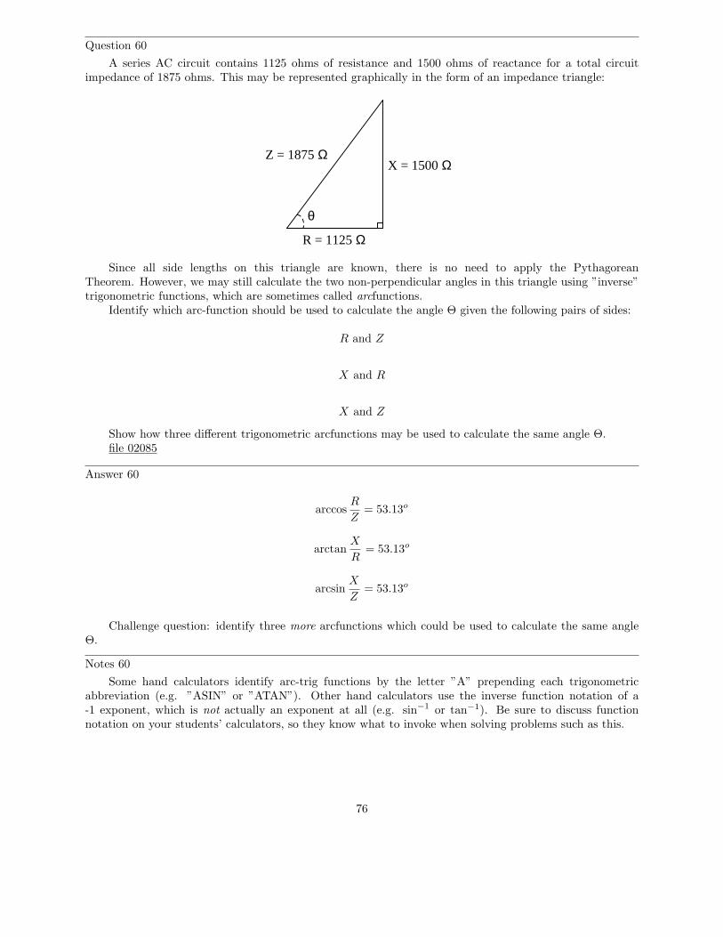
Question 60
A series AC circuit contains 1125 ohms of resistance and 1500 ohms of reactance for a total circuitimpedance of 1875 ohms. This may be represented graphically in the form of an impedance triangle:
θ
Z = 1875 Ω
R = 1125 Ω
X = 1500 Ω
Since all side lengths on this triangle are known, there is no need to apply the PythagoreanTheorem. However, we may still calculate the two non-perpendicular angles in this triangle using ”inverse”trigonometric functions, which are sometimes called arcfunctions.
Identify which arc-function should be used to calculate the angle Θ given the following pairs of sides:
R and Z
X and R
X and Z
Show how three different trigonometric arcfunctions may be used to calculate the same angle Θ.file 02085
Answer 60
arccosR
Z= 53.13o
arctanX
R= 53.13o
arcsinX
Z= 53.13o
Challenge question: identify three more arcfunctions which could be used to calculate the same angleΘ.
Notes 60
Some hand calculators identify arc-trig functions by the letter ”A” prepending each trigonometricabbreviation (e.g. ”ASIN” or ”ATAN”). Other hand calculators use the inverse function notation of a-1 exponent, which is not actually an exponent at all (e.g. sin−1 or tan−1). Be sure to discuss functionnotation on your students’ calculators, so they know what to invoke when solving problems such as this.
76
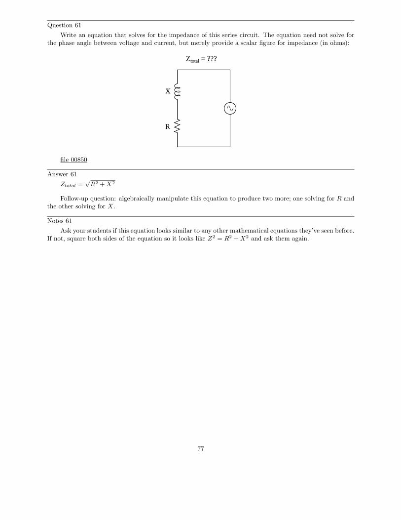
Question 61
Write an equation that solves for the impedance of this series circuit. The equation need not solve forthe phase angle between voltage and current, but merely provide a scalar figure for impedance (in ohms):
Ztotal = ???
R
X
file 00850
Answer 61
Ztotal =√
R2 + X2
Follow-up question: algebraically manipulate this equation to produce two more; one solving for R andthe other solving for X.
Notes 61
Ask your students if this equation looks similar to any other mathematical equations they’ve seen before.If not, square both sides of the equation so it looks like Z2 = R2 + X2 and ask them again.
77
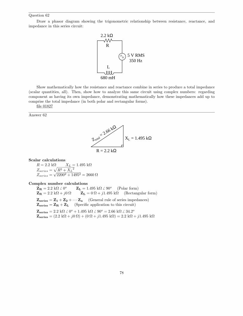
Question 62
Draw a phasor diagram showing the trigonometric relationship between resistance, reactance, andimpedance in this series circuit:
5 V RMS350 Hz
2.2 kΩ
680 mH
R
L
Show mathematically how the resistance and reactance combine in series to produce a total impedance(scalar quantities, all). Then, show how to analyze this same circuit using complex numbers: regardingcomponent as having its own impedance, demonstrating mathematically how these impedances add up tocomprise the total impedance (in both polar and rectangular forms).
file 01827
Answer 62
R = 2.2 kΩ
XL = 1.495 kΩZ total = 2.66 kΩ
Scalar calculationsR = 2.2 kΩ XL = 1.495 kΩ
Zseries =√
R2 + XL2
Zseries =√
22002 + 14952 = 2660 Ω
Complex number calculationsZR = 2.2 kΩ 6 0o ZL = 1.495 kΩ 6 90o (Polar form)ZR = 2.2 kΩ + j0 Ω ZL = 0 Ω + j1.495 kΩ (Rectangular form)
Zseries = Z1 + Z2 + · · ·Zn (General rule of series impedances)Zseries = ZR + ZL (Specific application to this circuit)
Zseries = 2.2 kΩ 6 0o + 1.495 kΩ 6 90o = 2.66 kΩ 6 34.2o
Zseries = (2.2 kΩ + j0 Ω) + (0 Ω + j1.495 kΩ) = 2.2 kΩ + j1.495 kΩ
78

Notes 62
I want students to see that there are two different ways of approaching a problem such as this: withscalar math and with complex number math. If students have access to calculators that can do complex-number arithmetic, the ”complex” approach is actually simpler for series-parallel combination circuits, andit yields richer (more informative) results.
Ask your students to determine which of the approaches most resembles DC circuit calculations.Incidentally, this is why I tend to prefer complex-number AC circuit calculations over scalar calculations:because of the conceptual continuity between AC and DC. When you use complex numbers to representAC voltages, currents, and impedances, almost all the rules of DC circuits still apply. The big exception, ofcourse, is calculations involving power.
79
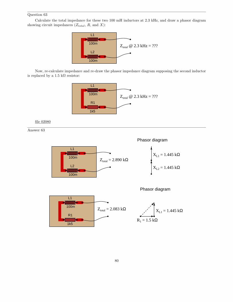
Question 63
Calculate the total impedance for these two 100 mH inductors at 2.3 kHz, and draw a phasor diagramshowing circuit impedances (Ztotal, R, and X):
L1
L2
100m
100m
Ztotal @ 2.3 kHz = ???
Now, re-calculate impedance and re-draw the phasor impedance diagram supposing the second inductoris replaced by a 1.5 kΩ resistor:
L1
100mZtotal @ 2.3 kHz = ???
R1
1k5
file 02080
Answer 63
L1
L2
100m
100m
Ztotal = 2.890 kΩ
Phasor diagram
XL1 = 1.445 kΩ
XL2 = 1.445 kΩ
L1
100m
R1
1k5
Phasor diagram
Ztotal = 2.083 kΩ XL1 = 1.445 kΩ
R1 = 1.5 kΩ
80

Notes 63
Phasor diagrams are powerful analytical tools, if one knows how to draw and interpret them. Withhand calculators being so powerful and readily able to handle complex numbers in either polar or rectangularform, there is temptation to avoid phasor diagrams and let the calculator handle all the angle manipulation.However, students will have a much better understanding of phasors and complex numbers in AC circuits ifyou hold them accountable to representing quantities in that form.
81
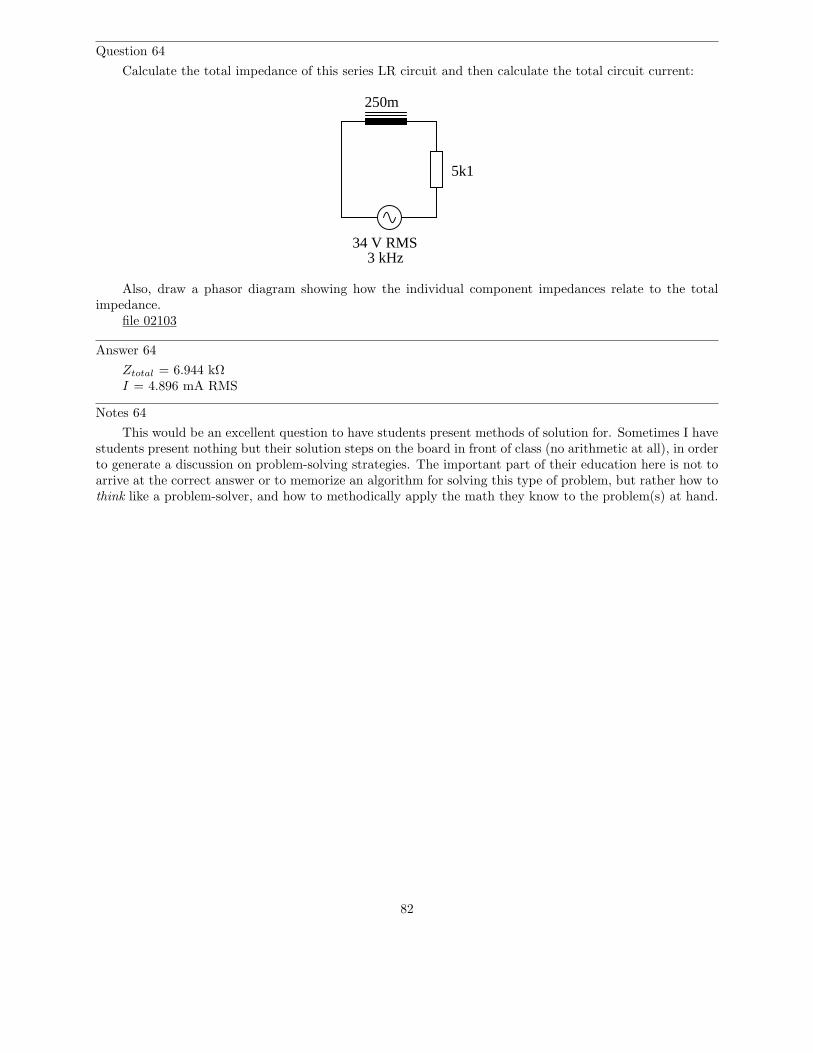
Question 64
Calculate the total impedance of this series LR circuit and then calculate the total circuit current:
3 kHz34 V RMS
250m
5k1
Also, draw a phasor diagram showing how the individual component impedances relate to the totalimpedance.
file 02103
Answer 64
Ztotal = 6.944 kΩI = 4.896 mA RMS
Notes 64
This would be an excellent question to have students present methods of solution for. Sometimes I havestudents present nothing but their solution steps on the board in front of class (no arithmetic at all), in orderto generate a discussion on problem-solving strategies. The important part of their education here is not toarrive at the correct answer or to memorize an algorithm for solving this type of problem, but rather how tothink like a problem-solver, and how to methodically apply the math they know to the problem(s) at hand.
82
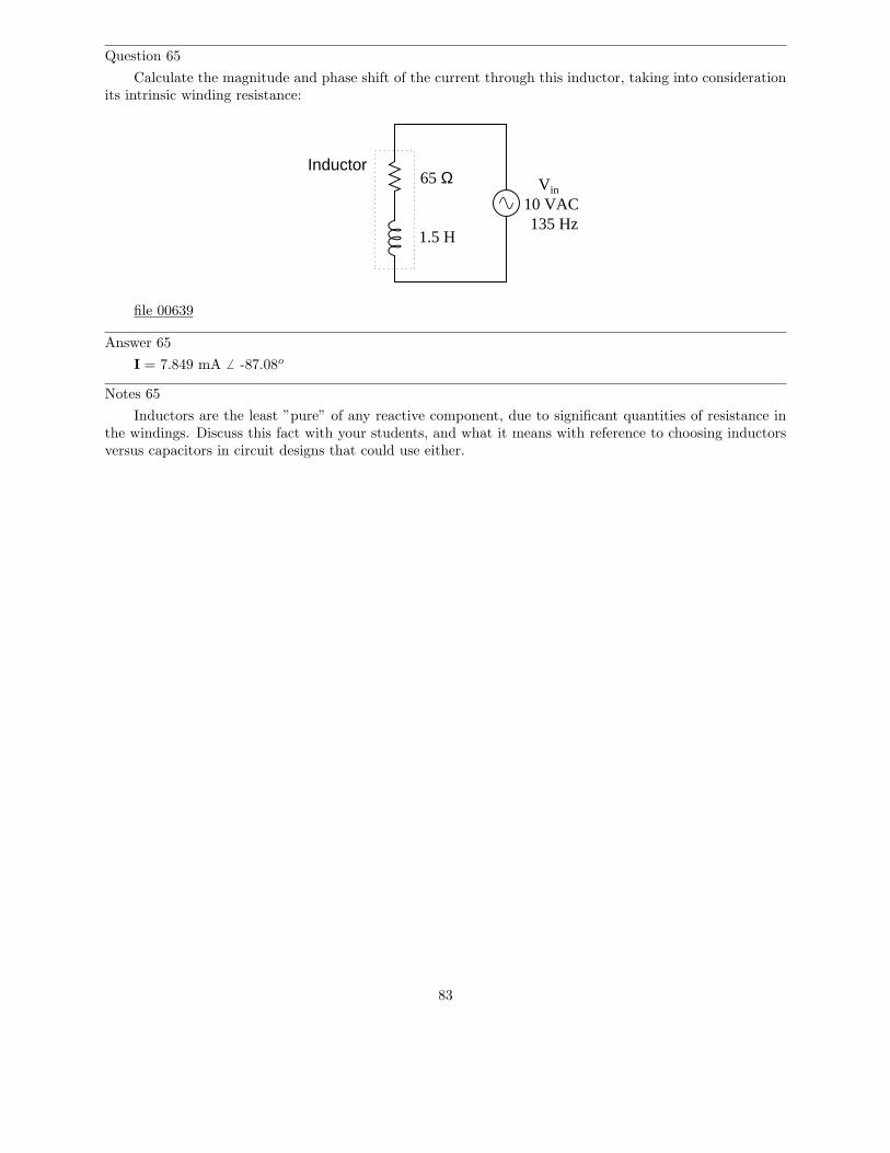
Question 65
Calculate the magnitude and phase shift of the current through this inductor, taking into considerationits intrinsic winding resistance:
Vin
10 VAC
Inductor
1.5 H
65 Ω
135 Hz
file 00639
Answer 65
I = 7.849 mA 6 -87.08o
Notes 65
Inductors are the least ”pure” of any reactive component, due to significant quantities of resistance inthe windings. Discuss this fact with your students, and what it means with reference to choosing inductorsversus capacitors in circuit designs that could use either.
83
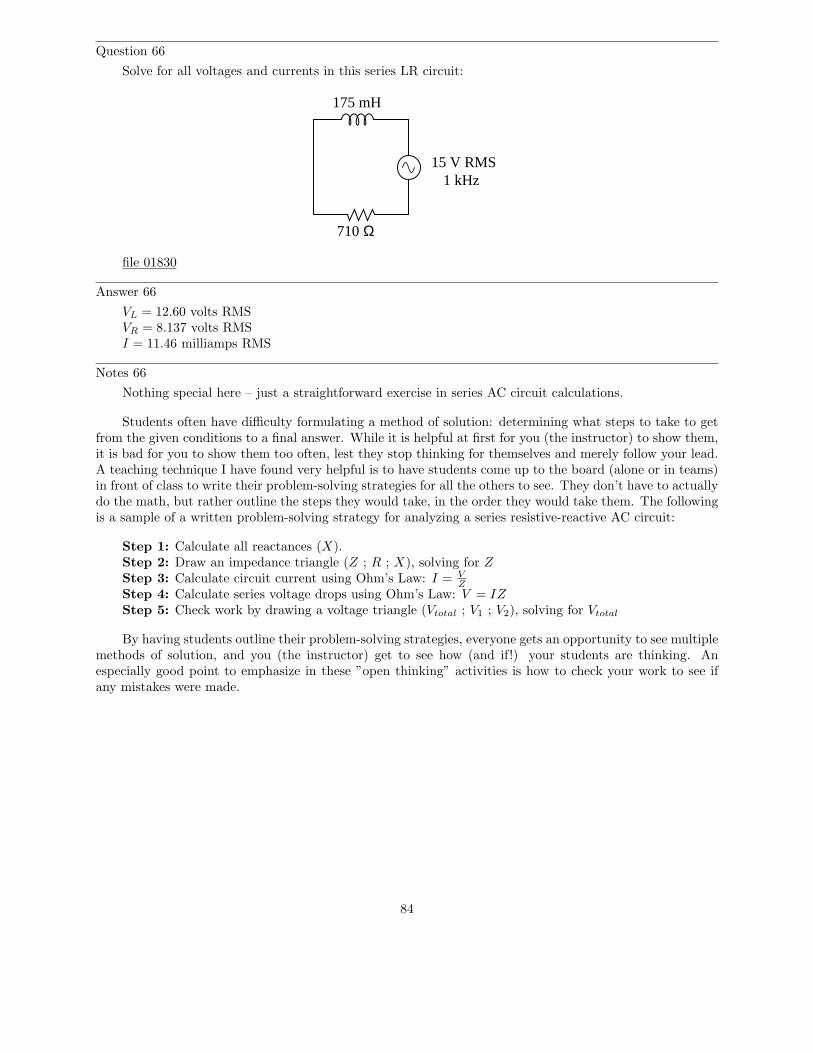
Question 66
Solve for all voltages and currents in this series LR circuit:
175 mH
15 V RMS1 kHz
710 Ω
file 01830
Answer 66
VL = 12.60 volts RMSVR = 8.137 volts RMSI = 11.46 milliamps RMS
Notes 66
Nothing special here – just a straightforward exercise in series AC circuit calculations.
Students often have difficulty formulating a method of solution: determining what steps to take to getfrom the given conditions to a final answer. While it is helpful at first for you (the instructor) to show them,it is bad for you to show them too often, lest they stop thinking for themselves and merely follow your lead.A teaching technique I have found very helpful is to have students come up to the board (alone or in teams)in front of class to write their problem-solving strategies for all the others to see. They don’t have to actuallydo the math, but rather outline the steps they would take, in the order they would take them. The followingis a sample of a written problem-solving strategy for analyzing a series resistive-reactive AC circuit:
Step 1: Calculate all reactances (X).Step 2: Draw an impedance triangle (Z ; R ; X), solving for Z
Step 3: Calculate circuit current using Ohm’s Law: I = VZ
Step 4: Calculate series voltage drops using Ohm’s Law: V = IZ
Step 5: Check work by drawing a voltage triangle (Vtotal ; V1 ; V2), solving for Vtotal
By having students outline their problem-solving strategies, everyone gets an opportunity to see multiplemethods of solution, and you (the instructor) get to see how (and if!) your students are thinking. Anespecially good point to emphasize in these ”open thinking” activities is how to check your work to see ifany mistakes were made.
84
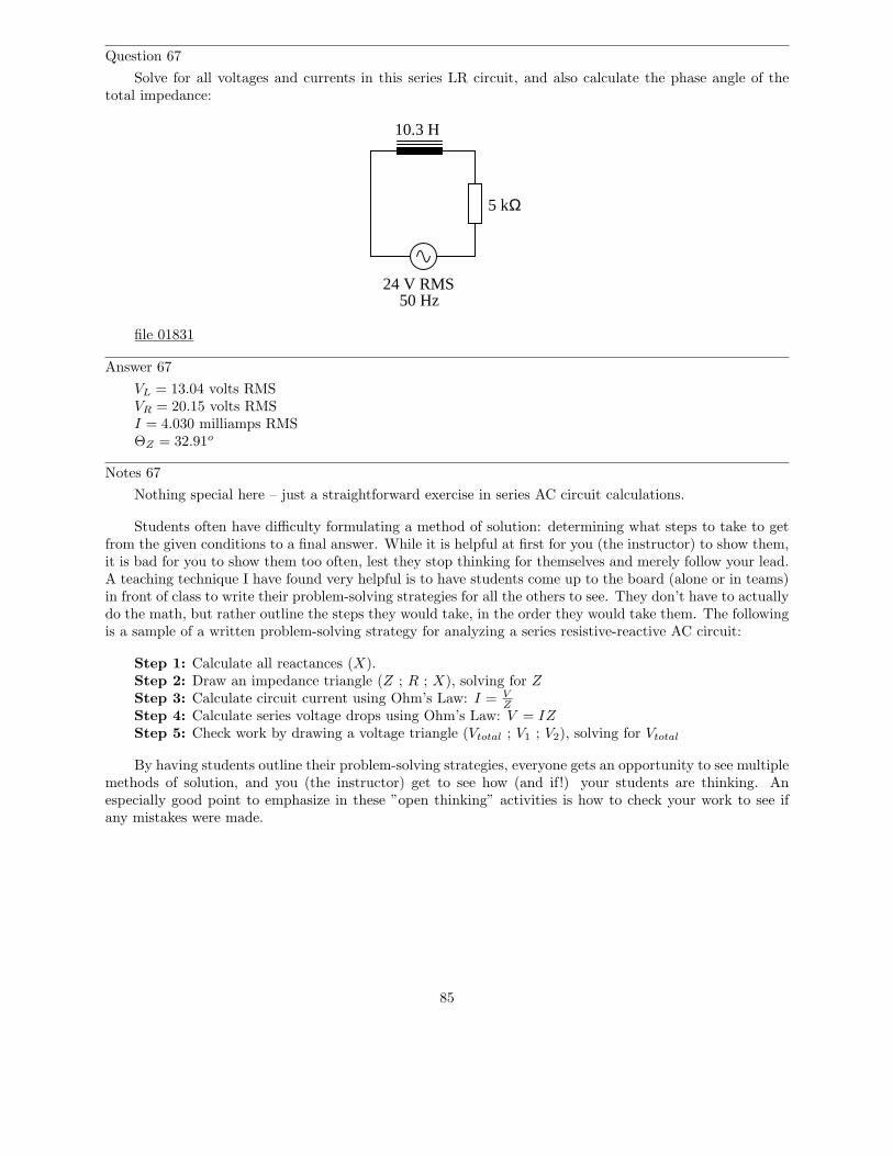
Question 67
Solve for all voltages and currents in this series LR circuit, and also calculate the phase angle of thetotal impedance:
5 kΩ
24 V RMS50 Hz
10.3 H
file 01831
Answer 67
VL = 13.04 volts RMSVR = 20.15 volts RMSI = 4.030 milliamps RMSΘZ = 32.91o
Notes 67
Nothing special here – just a straightforward exercise in series AC circuit calculations.
Students often have difficulty formulating a method of solution: determining what steps to take to getfrom the given conditions to a final answer. While it is helpful at first for you (the instructor) to show them,it is bad for you to show them too often, lest they stop thinking for themselves and merely follow your lead.A teaching technique I have found very helpful is to have students come up to the board (alone or in teams)in front of class to write their problem-solving strategies for all the others to see. They don’t have to actuallydo the math, but rather outline the steps they would take, in the order they would take them. The followingis a sample of a written problem-solving strategy for analyzing a series resistive-reactive AC circuit:
Step 1: Calculate all reactances (X).Step 2: Draw an impedance triangle (Z ; R ; X), solving for Z
Step 3: Calculate circuit current using Ohm’s Law: I = VZ
Step 4: Calculate series voltage drops using Ohm’s Law: V = IZ
Step 5: Check work by drawing a voltage triangle (Vtotal ; V1 ; V2), solving for Vtotal
By having students outline their problem-solving strategies, everyone gets an opportunity to see multiplemethods of solution, and you (the instructor) get to see how (and if!) your students are thinking. Anespecially good point to emphasize in these ”open thinking” activities is how to check your work to see ifany mistakes were made.
85
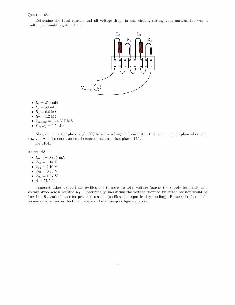
Question 68
Determine the total current and all voltage drops in this circuit, stating your answers the way amultimeter would register them:
L1 L2
R1 R2
Vsupply
• L1 = 250 mH• L2 = 60 mH• R1 = 6.8 kΩ• R2 = 1.2 kΩ• Vsupply = 13.4 V RMS• fsupply = 6.5 kHz
Also, calculate the phase angle (Θ) between voltage and current in this circuit, and explain where andhow you would connect an oscilloscope to measure that phase shift.
file 01841
Answer 68
• Itotal = 0.895 mA• VL1 = 9.14 V• VL2 = 2.19 V• VR1 = 6.08 V• VR2 = 1.07 V• Θ = 57.71o
I suggest using a dual-trace oscilloscope to measure total voltage (across the supply terminals) andvoltage drop across resistor R2. Theoretically, measuring the voltage dropped by either resistor would befine, but R2 works better for practical reasons (oscilloscope input lead grounding). Phase shift then couldbe measured either in the time domain or by a Lissajous figure analysis.
86

Notes 68
Some students many wonder what type of numerical result best corresponds to a multimeter’s readings,if they do their calculations using complex numbers (”do I use polar or rectangular form, and if rectangulardo I use the real or the imaginary part?”). The answers given for this question should clarify that point.
It is very important that students know how to apply this knowledge of AC circuit analysis to real-worldsituations. Asking students to determine how they would connect an oscilloscope to the circuit to measureΘ is an exercise in developing their abstraction abilities between calculations and actual circuit scenarios.
Students often have difficulty formulating a method of solution: determining what steps to take to getfrom the given conditions to a final answer. While it is helpful at first for you (the instructor) to show them,it is bad for you to show them too often, lest they stop thinking for themselves and merely follow your lead.A teaching technique I have found very helpful is to have students come up to the board (alone or in teams)in front of class to write their problem-solving strategies for all the others to see. They don’t have to actuallydo the math, but rather outline the steps they would take, in the order they would take them. The followingis a sample of a written problem-solving strategy for analyzing a series resistive-reactive AC circuit:
Step 1: Calculate all reactances (X).Step 2: Draw an impedance triangle (Z ; R ; X), solving for Z
Step 3: Calculate circuit current using Ohm’s Law: I = VZ
Step 4: Calculate series voltage drops using Ohm’s Law: V = IZ
Step 5: Check work by drawing a voltage triangle (Vtotal ; V1 ; V2), solving for Vtotal
By having students outline their problem-solving strategies, everyone gets an opportunity to see multiplemethods of solution, and you (the instructor) get to see how (and if!) your students are thinking. Anespecially good point to emphasize in these ”open thinking” activities is how to check your work to see ifany mistakes were made.
87
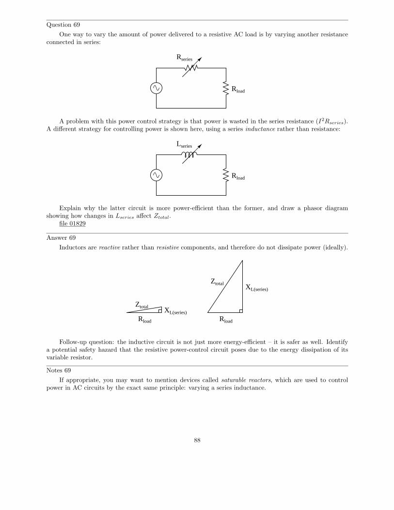
Question 69
One way to vary the amount of power delivered to a resistive AC load is by varying another resistanceconnected in series:
Rload
Rseries
A problem with this power control strategy is that power is wasted in the series resistance (I2Rseries).A different strategy for controlling power is shown here, using a series inductance rather than resistance:
Rload
Lseries
Explain why the latter circuit is more power-efficient than the former, and draw a phasor diagramshowing how changes in Lseries affect Ztotal.
file 01829
Answer 69
Inductors are reactive rather than resistive components, and therefore do not dissipate power (ideally).
Ztotal
Rload
XL(series)
Rload
XL(series)
Ztotal
Follow-up question: the inductive circuit is not just more energy-efficient – it is safer as well. Identifya potential safety hazard that the resistive power-control circuit poses due to the energy dissipation of itsvariable resistor.
Notes 69
If appropriate, you may want to mention devices called saturable reactors, which are used to controlpower in AC circuits by the exact same principle: varying a series inductance.
88
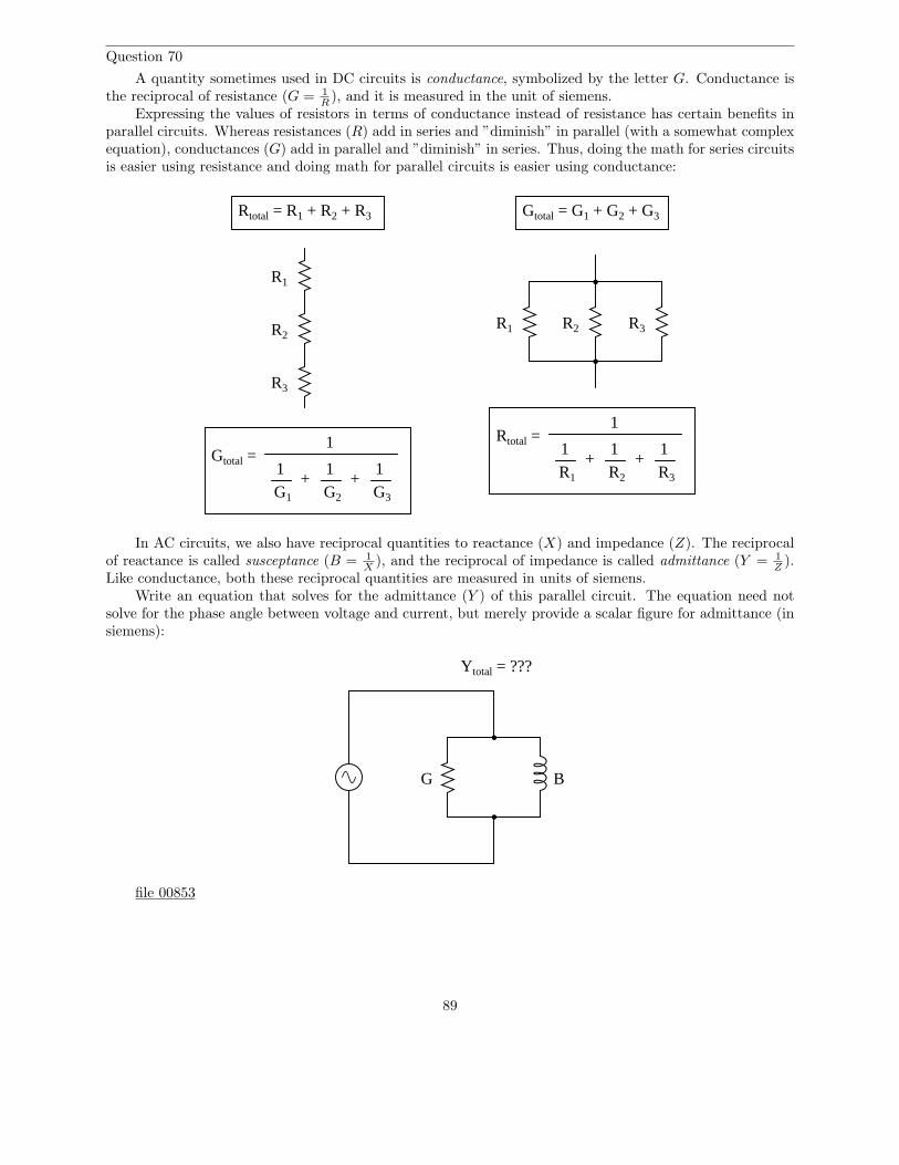
Question 70
A quantity sometimes used in DC circuits is conductance, symbolized by the letter G. Conductance isthe reciprocal of resistance (G = 1
R), and it is measured in the unit of siemens.
Expressing the values of resistors in terms of conductance instead of resistance has certain benefits inparallel circuits. Whereas resistances (R) add in series and ”diminish” in parallel (with a somewhat complexequation), conductances (G) add in parallel and ”diminish” in series. Thus, doing the math for series circuitsis easier using resistance and doing math for parallel circuits is easier using conductance:
R1
R2
R3
R1 R2 R3
Rtotal = R1 + R2 + R3 Gtotal = G1 + G2 + G3
Rtotal =1
R1
+1
+1
R2 R3
1
Gtotal =1
+1
+1
1
G1 G2 G3
In AC circuits, we also have reciprocal quantities to reactance (X) and impedance (Z). The reciprocalof reactance is called susceptance (B = 1
X), and the reciprocal of impedance is called admittance (Y = 1
Z).
Like conductance, both these reciprocal quantities are measured in units of siemens.Write an equation that solves for the admittance (Y ) of this parallel circuit. The equation need not
solve for the phase angle between voltage and current, but merely provide a scalar figure for admittance (insiemens):
G B
Ytotal = ???
file 00853
89
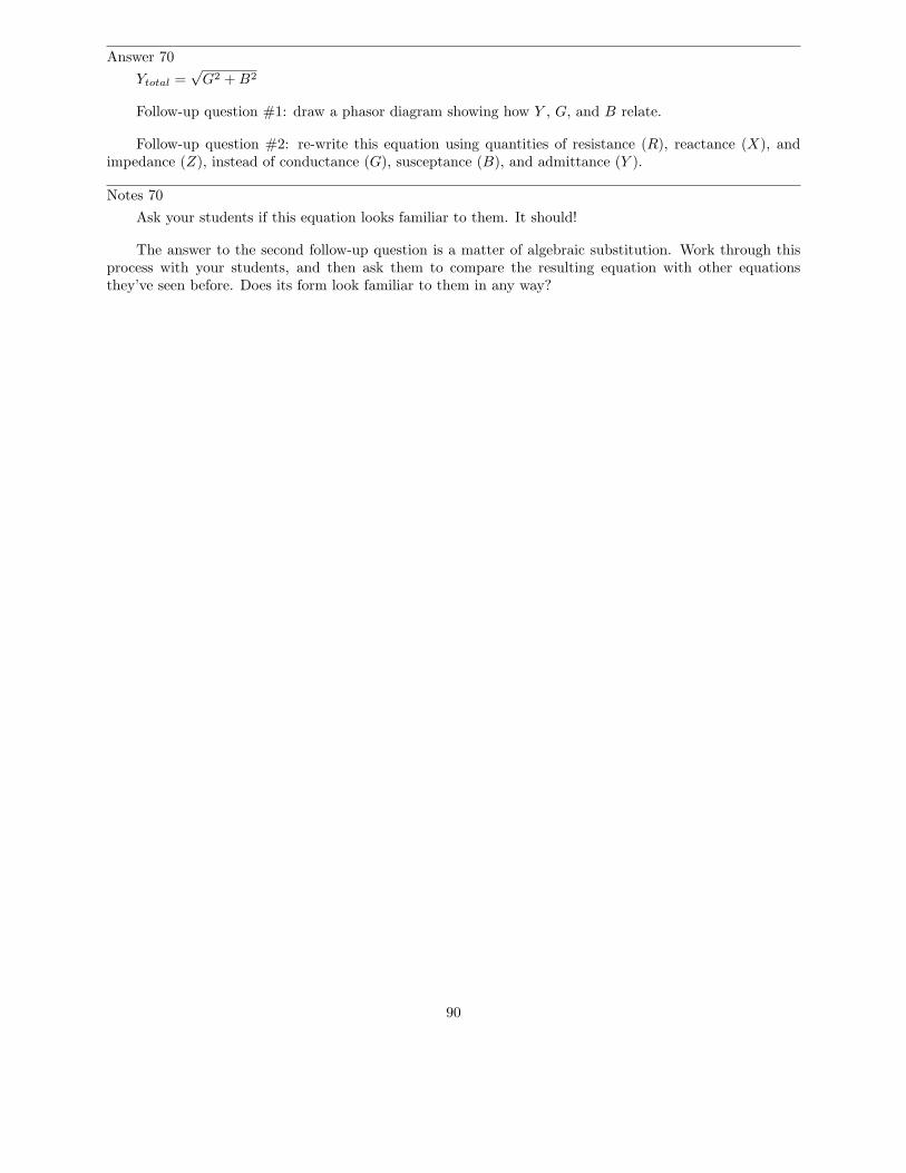
Answer 70
Ytotal =√
G2 + B2
Follow-up question #1: draw a phasor diagram showing how Y , G, and B relate.
Follow-up question #2: re-write this equation using quantities of resistance (R), reactance (X), andimpedance (Z), instead of conductance (G), susceptance (B), and admittance (Y ).
Notes 70
Ask your students if this equation looks familiar to them. It should!
The answer to the second follow-up question is a matter of algebraic substitution. Work through thisprocess with your students, and then ask them to compare the resulting equation with other equationsthey’ve seen before. Does its form look familiar to them in any way?
90
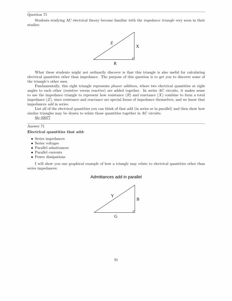
Question 71
Students studying AC electrical theory become familiar with the impedance triangle very soon in theirstudies:
R
XZ
What these students might not ordinarily discover is that this triangle is also useful for calculatingelectrical quantities other than impedance. The purpose of this question is to get you to discover some ofthe triangle’s other uses.
Fundamentally, this right triangle represents phasor addition, where two electrical quantities at rightangles to each other (resistive versus reactive) are added together. In series AC circuits, it makes senseto use the impedance triangle to represent how resistance (R) and reactance (X) combine to form a totalimpedance (Z), since resistance and reactance are special forms of impedance themselves, and we know thatimpedances add in series.
List all of the electrical quantities you can think of that add (in series or in parallel) and then show howsimilar triangles may be drawn to relate those quantities together in AC circuits.
file 02077
Answer 71
Electrical quantities that add:
• Series impedances• Series voltages• Parallel admittances• Parallel currents• Power dissipations
I will show you one graphical example of how a triangle may relate to electrical quantities other thanseries impedances:
YB
G
Admittances add in parallel
91

Notes 71
It is very important for students to understand that the triangle only works as an analysis tool whenapplied to quantities that add. Many times I have seen students try to apply the Z-R-X impedance triangleto parallel circuits and fail because parallel impedances do not add. The purpose of this question is to forcestudents to think about where the triangle is applicable to AC circuit analysis, and not just to use it blindly.
The power triangle is an interesting application of trigonometry applied to electric circuits. You maynot want to discuss power with your students in great detail if they are just beginning to study voltage andcurrent in AC circuits, because power is a sufficiently confusing subject on its own.
92
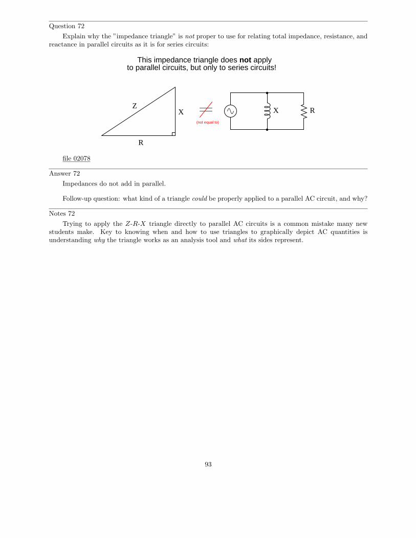
Question 72
Explain why the ”impedance triangle” is not proper to use for relating total impedance, resistance, andreactance in parallel circuits as it is for series circuits:
R
XZ
X R
This impedance triangle does not applyto parallel circuits, but only to series circuits!
(not equal to)
file 02078
Answer 72
Impedances do not add in parallel.
Follow-up question: what kind of a triangle could be properly applied to a parallel AC circuit, and why?
Notes 72
Trying to apply the Z-R-X triangle directly to parallel AC circuits is a common mistake many newstudents make. Key to knowing when and how to use triangles to graphically depict AC quantities isunderstanding why the triangle works as an analysis tool and what its sides represent.
93
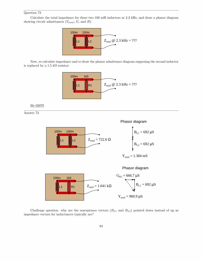
Question 73
Calculate the total impedance for these two 100 mH inductors at 2.3 kHz, and draw a phasor diagramshowing circuit admittances (Ytotal, G, and B):
L1 L2 Ztotal @ 2.3 kHz = ???
100m 100m
Now, re-calculate impedance and re-draw the phasor admittance diagram supposing the second inductoris replaced by a 1.5 kΩ resistor:
L1 Ztotal @ 2.3 kHz = ???
100m 1k5
R1
file 02079
Answer 73
L1 L2
100m 100m
Ztotal = 722.6 Ω
BL1 = 692 µS
BL2 = 692 µS
Ytotal = 1.384 mS
Phasor diagram
L1
100m 1k5
Ztotal = 1.041 kΩ BL1 = 692 µS
GR1 = 666.7 µS
Ytotal = 960.9 µS
Phasor diagram
R1
Challenge question: why are the susceptance vectors (BL1 and BL2) pointed down instead of up asimpedance vectors for inductances typically are?
94

Notes 73
Phasor diagrams are powerful analytical tools, if one knows how to draw and interpret them. Withhand calculators being so powerful and readily able to handle complex numbers in either polar or rectangularform, there is temptation to avoid phasor diagrams and let the calculator handle all the angle manipulation.However, students will have a much better understanding of phasors and complex numbers in AC circuits ifyou hold them accountable to representing quantities in that form.
95
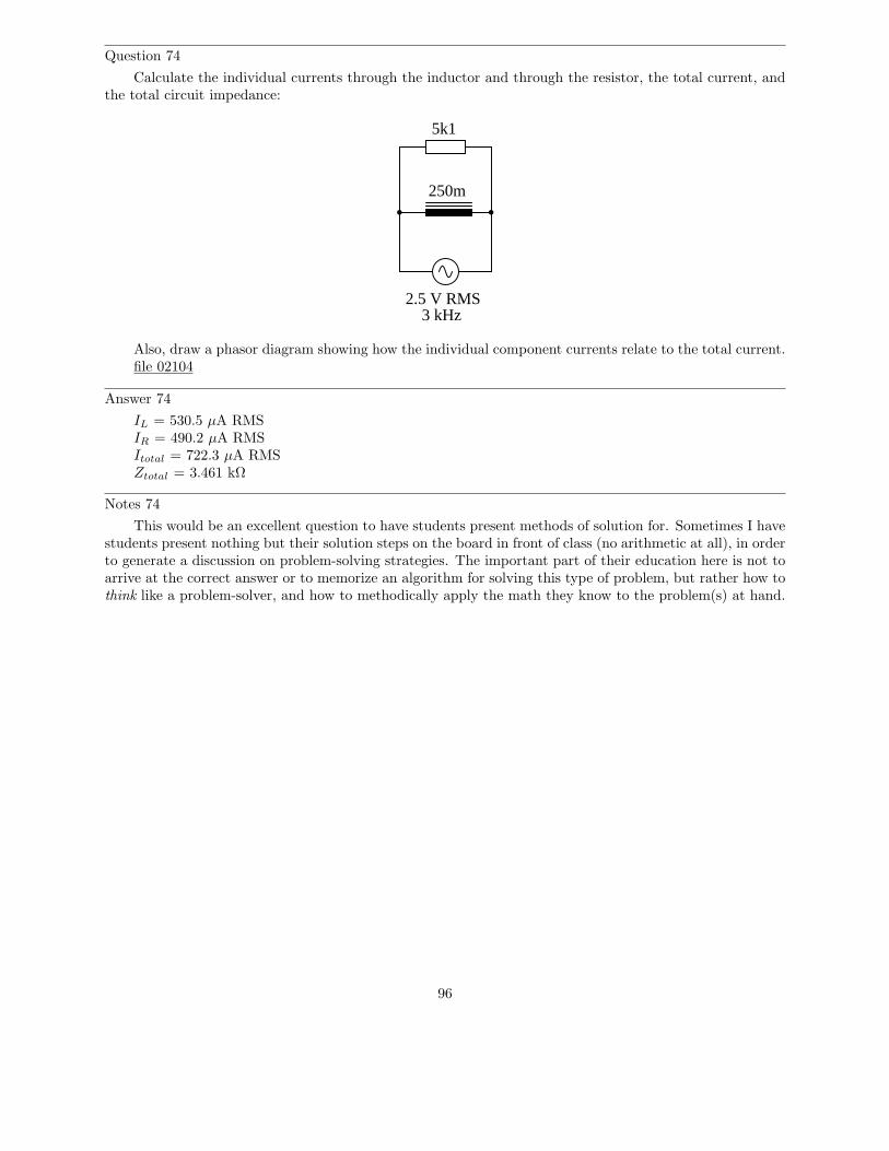
Question 74
Calculate the individual currents through the inductor and through the resistor, the total current, andthe total circuit impedance:
3 kHz
250m
5k1
2.5 V RMS
Also, draw a phasor diagram showing how the individual component currents relate to the total current.file 02104
Answer 74
IL = 530.5 µA RMSIR = 490.2 µA RMSItotal = 722.3 µA RMSZtotal = 3.461 kΩ
Notes 74
This would be an excellent question to have students present methods of solution for. Sometimes I havestudents present nothing but their solution steps on the board in front of class (no arithmetic at all), in orderto generate a discussion on problem-solving strategies. The important part of their education here is not toarrive at the correct answer or to memorize an algorithm for solving this type of problem, but rather how tothink like a problem-solver, and how to methodically apply the math they know to the problem(s) at hand.
96
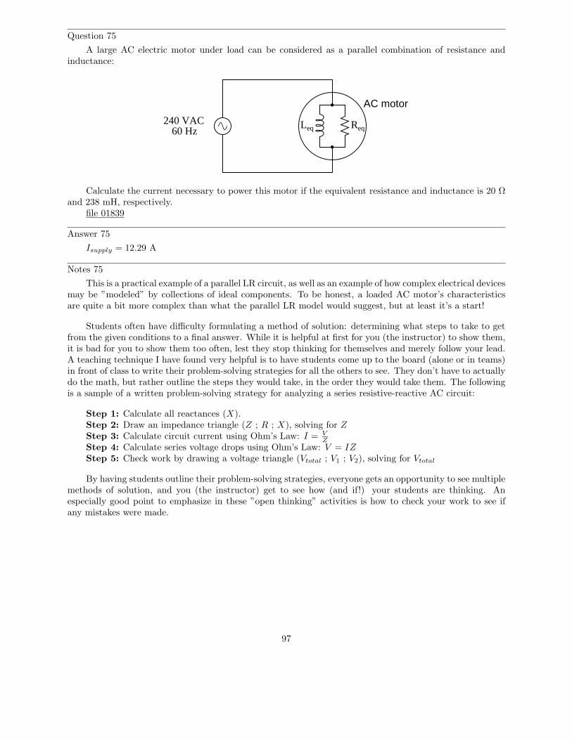
Question 75
A large AC electric motor under load can be considered as a parallel combination of resistance andinductance:
AC motor
240 VAC60 Hz
Leq Req
Calculate the current necessary to power this motor if the equivalent resistance and inductance is 20 Ωand 238 mH, respectively.
file 01839
Answer 75
Isupply = 12.29 A
Notes 75
This is a practical example of a parallel LR circuit, as well as an example of how complex electrical devicesmay be ”modeled” by collections of ideal components. To be honest, a loaded AC motor’s characteristicsare quite a bit more complex than what the parallel LR model would suggest, but at least it’s a start!
Students often have difficulty formulating a method of solution: determining what steps to take to getfrom the given conditions to a final answer. While it is helpful at first for you (the instructor) to show them,it is bad for you to show them too often, lest they stop thinking for themselves and merely follow your lead.A teaching technique I have found very helpful is to have students come up to the board (alone or in teams)in front of class to write their problem-solving strategies for all the others to see. They don’t have to actuallydo the math, but rather outline the steps they would take, in the order they would take them. The followingis a sample of a written problem-solving strategy for analyzing a series resistive-reactive AC circuit:
Step 1: Calculate all reactances (X).Step 2: Draw an impedance triangle (Z ; R ; X), solving for Z
Step 3: Calculate circuit current using Ohm’s Law: I = VZ
Step 4: Calculate series voltage drops using Ohm’s Law: V = IZ
Step 5: Check work by drawing a voltage triangle (Vtotal ; V1 ; V2), solving for Vtotal
By having students outline their problem-solving strategies, everyone gets an opportunity to see multiplemethods of solution, and you (the instructor) get to see how (and if!) your students are thinking. Anespecially good point to emphasize in these ”open thinking” activities is how to check your work to see ifany mistakes were made.
97
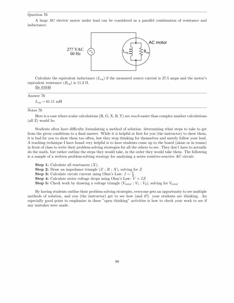
Question 76
A large AC electric motor under load can be considered as a parallel combination of resistance andinductance:
AC motor
60 HzLeq Req
277 VAC
Calculate the equivalent inductance (Leq) if the measured source current is 27.5 amps and the motor’sequivalent resistance (Req) is 11.2 Ω.
file 01840
Answer 76
Leq = 61.11 mH
Notes 76
Here is a case where scalar calculations (R, G, X, B, Y) are much easier than complex number calculations(all Z) would be.
Students often have difficulty formulating a method of solution: determining what steps to take to getfrom the given conditions to a final answer. While it is helpful at first for you (the instructor) to show them,it is bad for you to show them too often, lest they stop thinking for themselves and merely follow your lead.A teaching technique I have found very helpful is to have students come up to the board (alone or in teams)in front of class to write their problem-solving strategies for all the others to see. They don’t have to actuallydo the math, but rather outline the steps they would take, in the order they would take them. The followingis a sample of a written problem-solving strategy for analyzing a series resistive-reactive AC circuit:
Step 1: Calculate all reactances (X).Step 2: Draw an impedance triangle (Z ; R ; X), solving for Z
Step 3: Calculate circuit current using Ohm’s Law: I = VZ
Step 4: Calculate series voltage drops using Ohm’s Law: V = IZ
Step 5: Check work by drawing a voltage triangle (Vtotal ; V1 ; V2), solving for Vtotal
By having students outline their problem-solving strategies, everyone gets an opportunity to see multiplemethods of solution, and you (the instructor) get to see how (and if!) your students are thinking. Anespecially good point to emphasize in these ”open thinking” activities is how to check your work to see ifany mistakes were made.
98
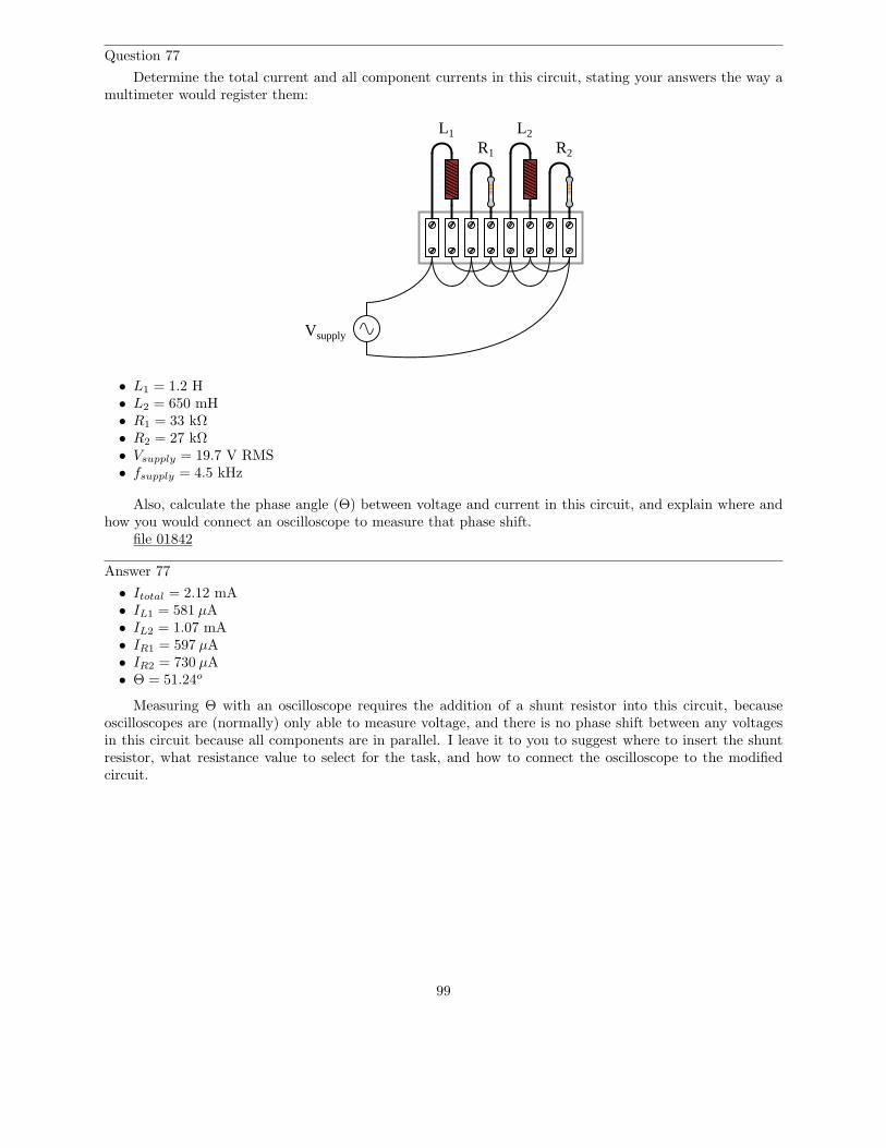
Question 77
Determine the total current and all component currents in this circuit, stating your answers the way amultimeter would register them:
L1 L2
R1 R2
Vsupply
• L1 = 1.2 H• L2 = 650 mH• R1 = 33 kΩ• R2 = 27 kΩ• Vsupply = 19.7 V RMS• fsupply = 4.5 kHz
Also, calculate the phase angle (Θ) between voltage and current in this circuit, and explain where andhow you would connect an oscilloscope to measure that phase shift.
file 01842
Answer 77
• Itotal = 2.12 mA• IL1 = 581 µA• IL2 = 1.07 mA• IR1 = 597 µA• IR2 = 730 µA• Θ = 51.24o
Measuring Θ with an oscilloscope requires the addition of a shunt resistor into this circuit, becauseoscilloscopes are (normally) only able to measure voltage, and there is no phase shift between any voltagesin this circuit because all components are in parallel. I leave it to you to suggest where to insert the shuntresistor, what resistance value to select for the task, and how to connect the oscilloscope to the modifiedcircuit.
99
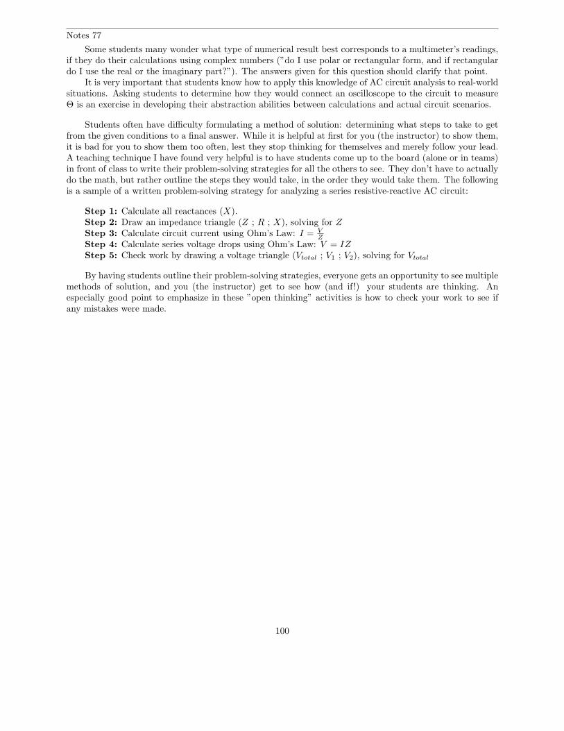
Notes 77
Some students many wonder what type of numerical result best corresponds to a multimeter’s readings,if they do their calculations using complex numbers (”do I use polar or rectangular form, and if rectangulardo I use the real or the imaginary part?”). The answers given for this question should clarify that point.
It is very important that students know how to apply this knowledge of AC circuit analysis to real-worldsituations. Asking students to determine how they would connect an oscilloscope to the circuit to measureΘ is an exercise in developing their abstraction abilities between calculations and actual circuit scenarios.
Students often have difficulty formulating a method of solution: determining what steps to take to getfrom the given conditions to a final answer. While it is helpful at first for you (the instructor) to show them,it is bad for you to show them too often, lest they stop thinking for themselves and merely follow your lead.A teaching technique I have found very helpful is to have students come up to the board (alone or in teams)in front of class to write their problem-solving strategies for all the others to see. They don’t have to actuallydo the math, but rather outline the steps they would take, in the order they would take them. The followingis a sample of a written problem-solving strategy for analyzing a series resistive-reactive AC circuit:
Step 1: Calculate all reactances (X).Step 2: Draw an impedance triangle (Z ; R ; X), solving for Z
Step 3: Calculate circuit current using Ohm’s Law: I = VZ
Step 4: Calculate series voltage drops using Ohm’s Law: V = IZ
Step 5: Check work by drawing a voltage triangle (Vtotal ; V1 ; V2), solving for Vtotal
By having students outline their problem-solving strategies, everyone gets an opportunity to see multiplemethods of solution, and you (the instructor) get to see how (and if!) your students are thinking. Anespecially good point to emphasize in these ”open thinking” activities is how to check your work to see ifany mistakes were made.
100
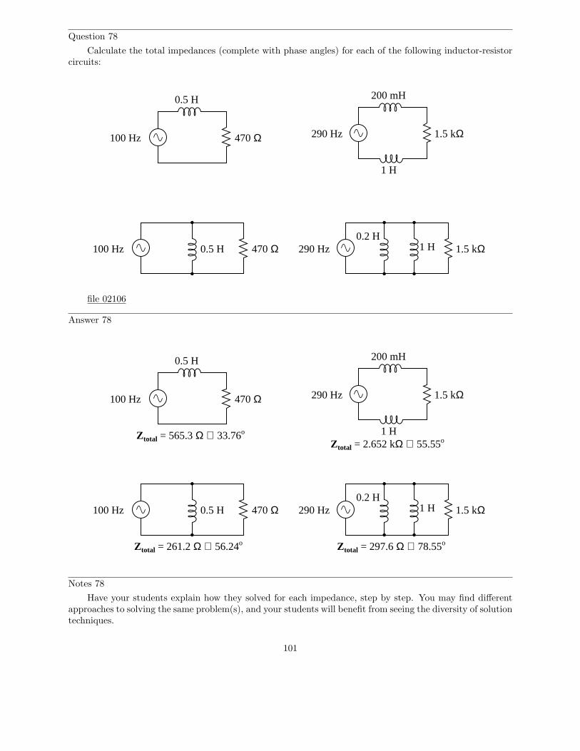
Question 78
Calculate the total impedances (complete with phase angles) for each of the following inductor-resistorcircuits:
100 Hz
0.5 H
470 Ω 290 Hz
1 H
200 mH
1.5 kΩ
100 Hz 0.5 H 470 Ω 290 Hz 1 H 1.5 kΩ0.2 H
file 02106
Answer 78
100 Hz
0.5 H
470 Ω 290 Hz
1 H
200 mH
1.5 kΩ
100 Hz 0.5 H 470 Ω 290 Hz 1 H 1.5 kΩ
Ztotal = 565.3 Ω ∠ 33.76o
Ztotal = 261.2 Ω ∠ 56.24o
Ztotal = 2.652 kΩ ∠ 55.55o
Ztotal = 297.6 Ω ∠ 78.55o
0.2 H
Notes 78
Have your students explain how they solved for each impedance, step by step. You may find differentapproaches to solving the same problem(s), and your students will benefit from seeing the diversity of solutiontechniques.
101
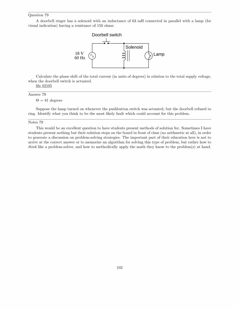
Question 79
A doorbell ringer has a solenoid with an inductance of 63 mH connected in parallel with a lamp (forvisual indication) having a resistance of 150 ohms:
60 Hz18 V
Doorbell switch
Solenoid
Lamp
Calculate the phase shift of the total current (in units of degrees) in relation to the total supply voltage,when the doorbell switch is actuated.
file 02105
Answer 79
Θ = 81 degrees
Suppose the lamp turned on whenever the pushbutton switch was actuated, but the doorbell refused toring. Identify what you think to be the most likely fault which could account for this problem.
Notes 79
This would be an excellent question to have students present methods of solution for. Sometimes I havestudents present nothing but their solution steps on the board in front of class (no arithmetic at all), in orderto generate a discussion on problem-solving strategies. The important part of their education here is not toarrive at the correct answer or to memorize an algorithm for solving this type of problem, but rather how tothink like a problem-solver, and how to methodically apply the math they know to the problem(s) at hand.
102
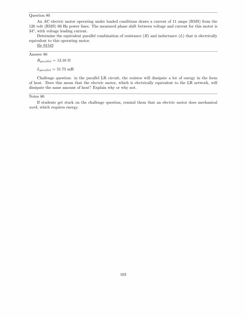
Question 80
An AC electric motor operating under loaded conditions draws a current of 11 amps (RMS) from the120 volt (RMS) 60 Hz power lines. The measured phase shift between voltage and current for this motor is34o, with voltage leading current.
Determine the equivalent parallel combination of resistance (R) and inductance (L) that is electricallyequivalent to this operating motor.
file 01542
Answer 80
Rparallel = 13.16 Ω
Lparallel = 51.75 mH
Challenge question: in the parallel LR circuit, the resistor will dissipate a lot of energy in the formof heat. Does this mean that the electric motor, which is electrically equivalent to the LR network, willdissipate the same amount of heat? Explain why or why not.
Notes 80
If students get stuck on the challenge question, remind them that an electric motor does mechanicalwork, which requires energy.
103
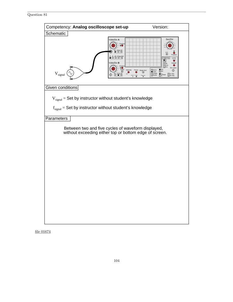
Question 81
Given conditions
Version:
Schematic
Parameters
Vsignal
fsignal = Set by instructor without student’s knowledge
Vsignal = Set by instructor without student’s knowledge
Between two and five cycles of waveform displayed,without exceeding either top or bottom edge of screen.
A B Alt Chop Add
Volts/Div A
Volts/Div B
DC Gnd AC
DC Gnd AC
Invert Intensity Focus
Position
Position
Position
Off
Beam find
LineExt.
AB
ACDC
NormAutoSingle
Slope
Level
Reset
X-Y
Holdoff
LF RejHF Rej
Triggering
Alt
Ext. input
Cal 1 V Gnd Trace rot.
Sec/Div0.5 0.2 0.1
1
10
5
2
20
50 m
20 m
10 m
5 m
2 m
0.5 0.2 0.11
10
5
2
20
50 m
20 m
10 m
5 m
2 m
1 m5 m
25 m
100 m
500 m
2.51
250 µ50 µ
10 µ
2.5 µ
0.5 µ
0.1 µ0.025 µ
off
Competency: Analog oscilloscope set-up
file 01674
104
Answer 81
You may use circuit simulation software to set up similar oscilloscope display interpretation scenarios,for practice or for verification of what you see in this exercise.
Notes 81
An oscilloscope is nothing more than a graphical voltmeter, having the ability to represent fast-changingvoltages over time in the form of a graph. It is very important for all students of electronics to learn how touse an oscilloscope well!
Use a sine-wave function generator for the AC voltage source, and be sure set the frequency to somereasonable value (well within the capability of both the oscilloscope and counter to measure).
If this is not the first time students have done this, be sure to “mess up” the oscilloscope controls priorto them making adjustments. Students must learn how to quickly configure an oscilloscope’s controls todisplay any arbitrary waveform, if they are to be proficient in using an oscilloscope as a diagnostic tool.
General concepts and principles to emphasize
• Basic oscilloscope operation (vertical sensitivity, coupling, timebase, triggering)• Location of “ground” connections on both the oscilloscope and signal generator• Relationship between the period of a wave and its frequency
Suggestions for Socratic discussion and experimentation
• What is the distinction between a waveform’s peak voltage value and its peak-to-peak voltage value?• Demonstrate how to make the waveform appear taller (i.e. each cycle extending farther along the
vertical axis) on the oscilloscope’s display.• Demonstrate how to make the waveform appear longer (i.e. each cycle extending farther along the
horizontal axis) on the oscilloscope’s display.• Demonstrate how to set the triggering value for the oscilloscope, and what difference that makes in the
displayed waveform.
105
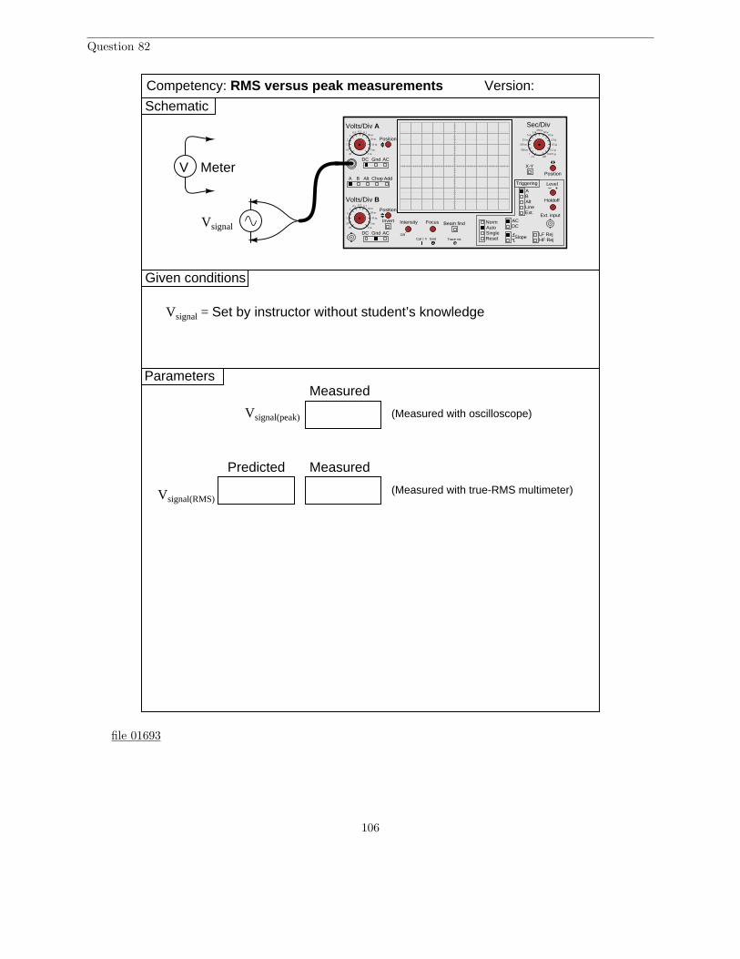
Question 82
Given conditions
Version:
Schematic
Parameters
Vsignal
Vsignal = Set by instructor without student’s knowledge
Competency: RMS versus peak measurements
Predicted Measured
Vsignal(RMS)
Measured
Vsignal(peak)
V Meter
(Measured with oscilloscope)
(Measured with true-RMS multimeter)
A B Alt Chop Add
Volts/Div A
Volts/Div B
DC Gnd AC
DC Gnd AC
Invert Intensity Focus
Position
Position
Position
Off
Beam find
LineExt.
AB
ACDC
NormAutoSingle
Slope
Level
Reset
X-Y
Holdoff
LF RejHF Rej
Triggering
Alt
Ext. input
Cal 1 V Gnd Trace rot.
Sec/Div0.5 0.2 0.1
1
10
5
2
20
50 m
20 m
10 m
5 m
2 m
0.5 0.2 0.11
10
5
2
20
50 m
20 m
10 m
5 m
2 m
1 m5 m
25 m
100 m
500 m
2.51
250 µ50 µ
10 µ
2.5 µ
0.5 µ
0.1 µ0.025 µ
off
file 01693
106
Answer 82
You may use circuit simulation software to set up similar oscilloscope display interpretation scenarios,for practice or for verification of what you see in this exercise.
Notes 82
Use a sine-wave function generator for the AC voltage source, and be sure set the frequency to somereasonable value (well within the capability of a multimeter to measure). It is very important that studentslearn to convert between peak and RMS measurements for sine waves, but you might want to mix thingsup a bit by having them do the same with triangle waves and square waves as well! It is vital that studentsrealize the rule of VRMS =
Vpeak√2
only holds for sinusoidal signals.
An important point to note in this exercise is that the “variable” adjustment on the vertical sensitivityfor the input channel must be turned fully so that the knob “clicks” into its calibrated position. If thisfine-adjustment is not set in the calibrated position, your voltage measurements will be inaccurate!
If you do choose to challenge students with non-sinusoidal waveshapes, be very sure that they dotheir voltmeter measurements using true-RMS meters! This means no analog voltmeters, which are“miscalibrated” so their inherently average-responding movements register (sinusoidal) RMS accurately.Your students must use true-RMS digital voltmeters in order for their non-sinusoidal RMS measurements tocorrelate with their calculations.
Incidentally, this lab exercise also works well as a demonstration of the importance of true-RMSindicating meters, comparing the indications of analog, non-true-RMS digital, and true-RMS digital onthe same non-sinusoidal waveform!
General concepts and principles to emphasize
• The concept of “Root-Mean-Square” (RMS) measurement• Basic oscilloscope operation (vertical sensitivity, coupling, timebase, triggering)• Location of “ground” connections on both the oscilloscope and signal generator
Suggestions for Socratic discussion and experimentation
• Explain what the “RMS” (Root-Mean-Square) value means for any AC waveform.• If you change the frequency of the AC source, does this affect its RMS or peak voltage value? Why or
why not?• A common misconception among students is that the RMS value of any waveform is always equal to
0.707 times the waveform’s peak value. Refute this misconception with a demonstrated example!
107
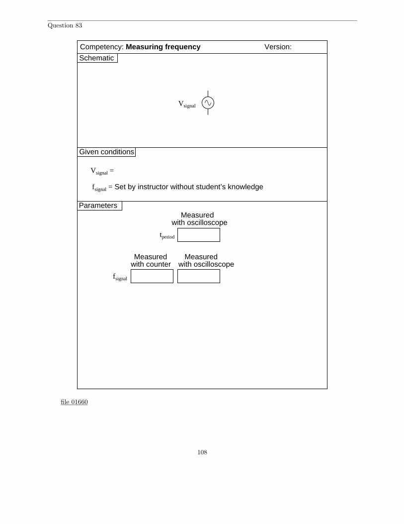
Question 83
Given conditions
Version:
Schematic
Parameters
Measured
Vsignal
Vsignal =
Competency: Measuring frequency
fsignal = Set by instructor without student’s knowledge
Measuredwith counter with oscilloscope
fsignal
tperiod
Measuredwith oscilloscope
file 01660
108
Answer 83
You may use circuit simulation software to set up similar oscilloscope display interpretation scenarios,for practice or for verification of what you see in this exercise.
Notes 83
Use a sine-wave function generator for the AC voltage source, and be sure set the frequency to somereasonable value (well within the capability of both the oscilloscope and counter to measure).
An important point to note in this exercise is that the “variable” adjustment on the horizontal timebasemust be turned fully so that the knob “clicks” into its calibrated position. If this fine-adjustment is notset in the calibrated position, your time measurements (and therefore your frequency calculations) will beinaccurate!
General concepts and principles to emphasize
• Relationship between the period of a wave and its frequency• Basic oscilloscope operation (vertical sensitivity, coupling, timebase, triggering)
Suggestions for Socratic discussion and experimentation
• The standard unit of measurement for period is seconds (s). The standard unit of measurement forfrequency is Hertz (Hz), which means “cycles per second.” However, an alternate unit of measurementfor frequency is inverse seconds, or s−1. Explain why Hz = s−1.
• If you change the voltage level of the AC source, does this affect its frequency? Why or why not?
109
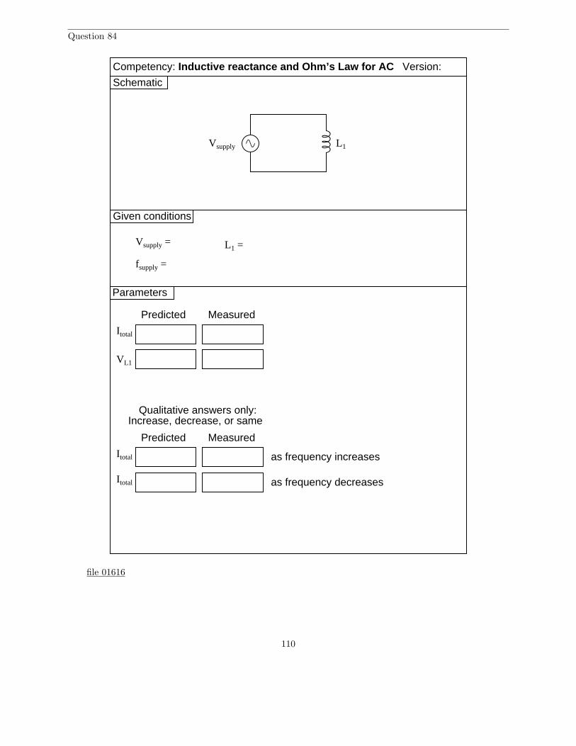
Question 84
Given conditions
Vsupply =
Predicted Measured
Itotal
Version:
Schematic
Parameters
Vsupply
Competency: Inductive reactance and Ohm’s Law for AC
L1
fsupply =
L1 =
VL1
Itotal
Predicted Measured
as frequency increases
Qualitative answers only:Increase, decrease, or same
Itotal as frequency decreases
file 01616
110
Answer 84
Use circuit simulation software to verify your predicted and measured parameter values.
Notes 84
In this exercise you will explore the concept of reactance, which is a form of opposition to the flow ofelectric current that is similar to but not identical to resistance. The distinction between reactance andresistance is a consequence of energy flow in an electrical component: components which transfer electricalenergy out of the circuit and into some other form (such as heat in the case of a resistor or mechanical workin the case of an electric motor) exhibit resistance; components which have the ability to absorb energy fromthe circuit and return energy back into the circuit (e.g. inductors and capacitors) exhibit reactance.
In order to achieve results closely approximating ideal, you need to use an inductor that has very littlewire resistance (the less, the better!). Your multimeter will be useful here to measure the DC resistance of theinductor – which is strictly a function of wire resistance and not inductance – and allow you to identify themost suitable inductor for this exercise. The problem with resistance is that it is a fundamentally differentkind of opposition to electric current. If your inductor happens to possess a lot of resistance (in addition toinductive reactance), the results will be skewed by the presence of this resistance.
Use a sine-wave function generator for the AC voltage source. I recommend against using line-powerAC because of strong harmonic frequencies which may be present (due to nonlinear loads operating on thesame power circuit).
If students are to use a multimeter to make their current and voltage measurements, be sure it is capableof accurate measurement at the circuit frequency! Inexpensive digital multimeters often experience difficultymeasuring AC voltage and current toward the high end of the audio-frequency range.
General concepts and principles to emphasize
• Self-induction (i.e. how a single coil is able to experience induction as a consequence of a changingcurrent passing through it)
• The concept of reactance, and how it differs from resistance• The relationship between inductance, frequency, and inductive reactance
Suggestions for Socratic discussion and experimentation
• Identify ways the inductor could be modified so as to possess more inductance.• Explain how reactance differs from resistance, even though they are both quantified using the same unit
of measurement: ohms (Ω).• Explain why current changes as source frequency changes, despite voltage remaining the same.• A technique used in making wire-wound resistors is something called a bifilar winding. Bifilar windings
have nearly zero inductance. Research how a bifilar winding is made, and then explain how it works tominimize induction and also why this might be important for making resistors.
111
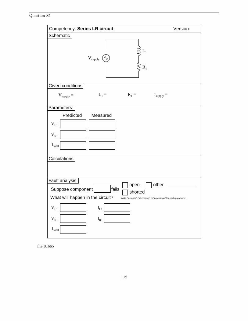
Question 85
Given conditions
Vsupply =
Predicted Measured
Version:
Schematic
Parameters
Vsupply
fsupply =
R1
R1 =
VR1
Itotal
L1
L1 =
VL1
Competency: Series LR circuit
Calculations
Fault analysis
Suppose component fails open
shorted
other
What will happen in the circuit?
VR1
Itotal
VL1 IL1
IR1
Write "increase", "decrease", or "no change" for each parameter:
file 01665
112
Answer 85
Use circuit simulation software to verify your predicted and measured parameter values.
Notes 85
In order to achieve results closely approximating ideal, you need to use an inductor that has very littlewire resistance (the less, the better!). Your multimeter will be useful here to measure the DC resistance of theinductor – which is strictly a function of wire resistance and not inductance – and allow you to identify themost suitable inductor for this exercise. The problem with resistance is that it is a fundamentally differentkind of opposition to electric current. If your inductor happens to possess a lot of resistance (in addition toinductive reactance), the results will be skewed by the presence of this resistance.
Use a sine-wave function generator for the AC voltage source. I recommend against using line-powerAC because of strong harmonic frequencies which may be present (due to nonlinear loads operating on thesame power circuit). Specify standard resistor and inductor values.
If students are to use a multimeter to make their current and voltage measurements, be sure it is capableof accurate measurement at the circuit frequency! Inexpensive digital multimeters often experience difficultymeasuring AC voltage and current toward the high end of the audio-frequency range.
An extension of this exercise is to incorporate troubleshooting questions. Whether using this exercise asa performance assessment or simply as a concept-building lab, you might want to follow up your students’results by asking them to predict the consequences of certain circuit faults.
General concepts and principles to emphasize
• The concept of reactance, and how it differs from resistance• The concept of impedance, and how it relates to both resistance and reactance• The relationship between inductance, frequency, and inductive reactance
Suggestions for Socratic discussion and experimentation
• Explain how reactance differs from resistance, even though they are both quantified using the same unitof measurement: ohms (Ω).
• What will happen to the amount of current in this circuit if the source frequency is increased (assuminga constant source voltage)?
• What will happen to the amount of current in this circuit if the inductor is replaced by another havinggreater inductance?
• What will happen to the amount of current in this circuit if the resistor is replaced by another havinggreater resistance?
• Explain why the sum of the resistor’s voltage and the inductor’s voltage does not equal the sourcevoltage.
113
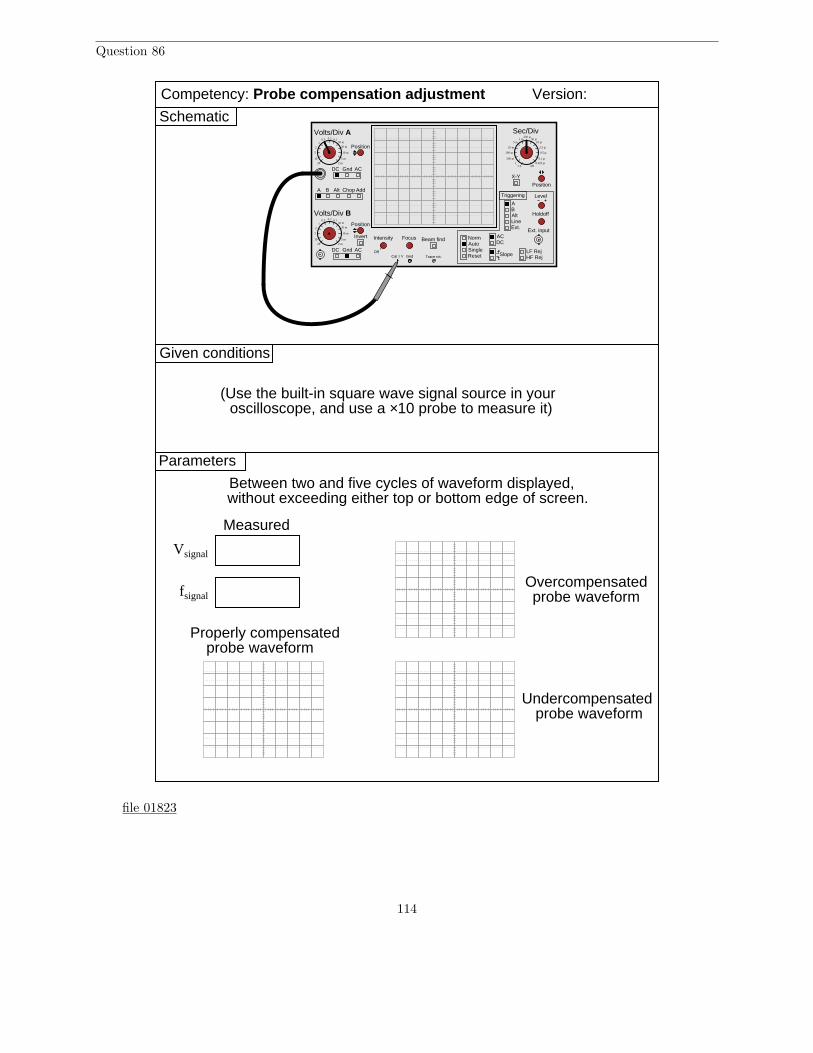
Question 86
Given conditions
Version:
Schematic
Parameters
Between two and five cycles of waveform displayed,without exceeding either top or bottom edge of screen.
A B Alt Chop Add
Volts/Div A
Volts/Div B
DC Gnd AC
DC Gnd AC
Invert Intensity Focus
Position
Position
Position
Off
Beam find
LineExt.
AB
ACDC
NormAutoSingle
Slope
Level
Reset
X-Y
Holdoff
LF RejHF Rej
Triggering
Alt
Ext. input
Cal 1 V Gnd Trace rot.
Sec/Div0.5 0.2 0.1
1
10
5
2
20
50 m
20 m
10 m
5 m
2 m
0.5 0.2 0.11
10
5
2
20
50 m
20 m
10 m
5 m
2 m
1 m5 m
25 m
100 m
500 m
2.51
250 µ50 µ
10 µ
2.5 µ
0.5 µ
0.1 µ0.025 µ
off
Competency: Probe compensation adjustment
Measured
Vsignal
fsignalOvercompensatedprobe waveform
Undercompensatedprobe waveform
Properly compensatedprobe waveform
(Use the built-in square wave signal source in youroscilloscope, and use a ×10 probe to measure it)
file 01823
114
Answer 86
There really isn’t much you can do to verify your experimental results. That’s okay, though, becausethe results are qualitative anyway.
Notes 86
If the oscilloscope does not have its own internal square-wave signal source, use a function generator setup to output square waves at 1 volt peak-to-peak at a frequency of 1 kHz.
If this is not the first time students have done this, be sure to “mess up” the oscilloscope controls priorto them making adjustments. Students must learn how to quickly configure an oscilloscope’s controls todisplay any arbitrary waveform, if they are to be proficient in using an oscilloscope as a diagnostic tool.
General concepts and principles to emphasize
• Basic oscilloscope operation (vertical sensitivity, coupling, timebase, triggering)• Relationship between the period of a wave and its frequency
Suggestions for Socratic discussion and experimentation
• Demonstrate how to make the waveform appear taller (i.e. each cycle extending farther along thevertical axis) on the oscilloscope’s display.
• Demonstrate how to make the waveform appear longer (i.e. each cycle extending farther along thehorizontal axis) on the oscilloscope’s display.
• Explain why changes in the triggering level don’t seem to affect the displayed waveform at all.
115

Question 87
Conclusions(i.e. What this tells me . . . )
Troubleshooting log
(i.e. What I did and/or noticed . . . )Actions / Measurements / Observations
file 03933
116

Answer 87
I do not provide a grading rubric here, but elsewhere.
Notes 87
The idea of a troubleshooting log is three-fold. First, it gets students in the habit of documentingtheir troubleshooting procedure and thought process. This is a valuable habit to get into, as it translatesto more efficient (and easier-followed) troubleshooting on the job. Second, it provides a way to documentstudent steps for the assessment process, making your job as an instructor easier. Third, it reinforces thenotion that each and every measurement or action should be followed by reflection (conclusion), making thetroubleshooting process more efficient.
117
Question 88
NAME: Troubleshooting Grading CriteriaYou will receive the highest score for which all criteria are met.
100 % (Must meet or exceed all criteria listed)A. Absolutely flawless procedureB. No unnecessary actions or measurements taken
90 % (Must meet or exceed these criteria in addition to all criteria for 85% and below)A. No reversals in procedure (i.e. changing mind without sufficient evidence)B. Every single action, measurement, and relevant observation properly documented
80 % (Must meet or exceed these criteria in addition to all criteria for 75% and below)A. No more than one unnecessary action or measurementB. No false conclusions or conceptual errorsC. No missing conclusions (i.e. at least one documented conclusion for action / measurement / observation)
70 % (Must meet or exceed these criteria in addition to all criteria for 65%)A. No more than one false conclusion or conceptual errorB. No more than one conclusion missing (i.e. an action, measurement, or relevant observation without a
corresponding conclusion)
65 % (Must meet or exceed these criteria in addition to all criteria for 60%)A. No more than two false conclusions or conceptual errorsB. No more than two unnecessary actions or measurementsC. No more than one undocumented action, measurement, or relevant observationD. Proper use of all test equipment
60 % (Must meet or exceed these criteria)A. Fault accurately identifiedB. Safe procedures used at all times
50 % (Only applicable where students performed significant development/design work – i.e. not a provencircuit provided with all component values)A. Working prototype circuit built and demonstrated
0 % (If any of the following conditions are true)A. Unsafe procedure(s) used at any point
file 03932
Answer 88
Be sure to document all steps taken and conclusions made in your troubleshooting!
Notes 88
The purpose of this assessment rubric is to act as a sort of “contract” between you (the instructor) andyour student. This way, the expectations are all clearly known in advance, which goes a long way towarddisarming problems later when it is time to grade.
118

Question 89
Determine the frequency of a waveform having a period of 1.4 milliseconds (1.4 ms).file 03276
Answer 89
f = 714.29 Hz
Notes 89
It is important for students to realize the reciprocal relationship between frequency and period. One iscycles per second while the other is seconds per cycle.
119
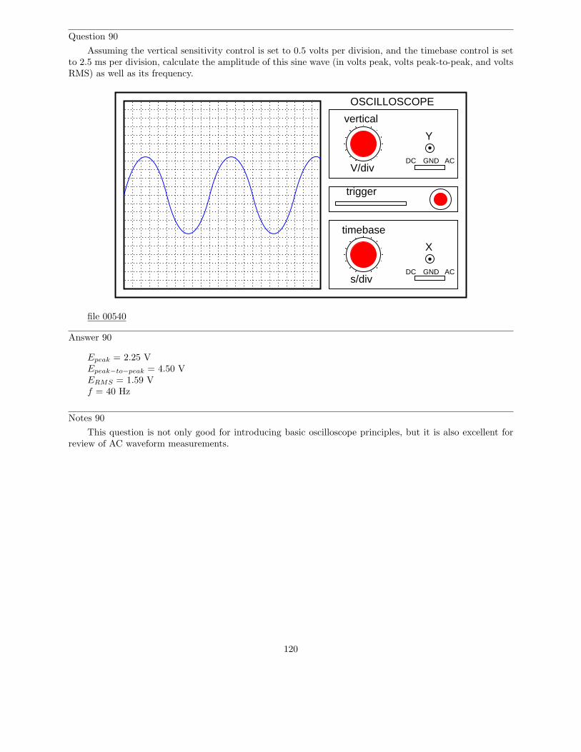
Question 90
Assuming the vertical sensitivity control is set to 0.5 volts per division, and the timebase control is setto 2.5 ms per division, calculate the amplitude of this sine wave (in volts peak, volts peak-to-peak, and voltsRMS) as well as its frequency.
trigger
timebase
s/divDC GND AC
X
GNDDCV/div
vertical
OSCILLOSCOPE
Y
AC
file 00540
Answer 90
Epeak = 2.25 VEpeak−to−peak = 4.50 VERMS = 1.59 Vf = 40 Hz
Notes 90
This question is not only good for introducing basic oscilloscope principles, but it is also excellent forreview of AC waveform measurements.
120
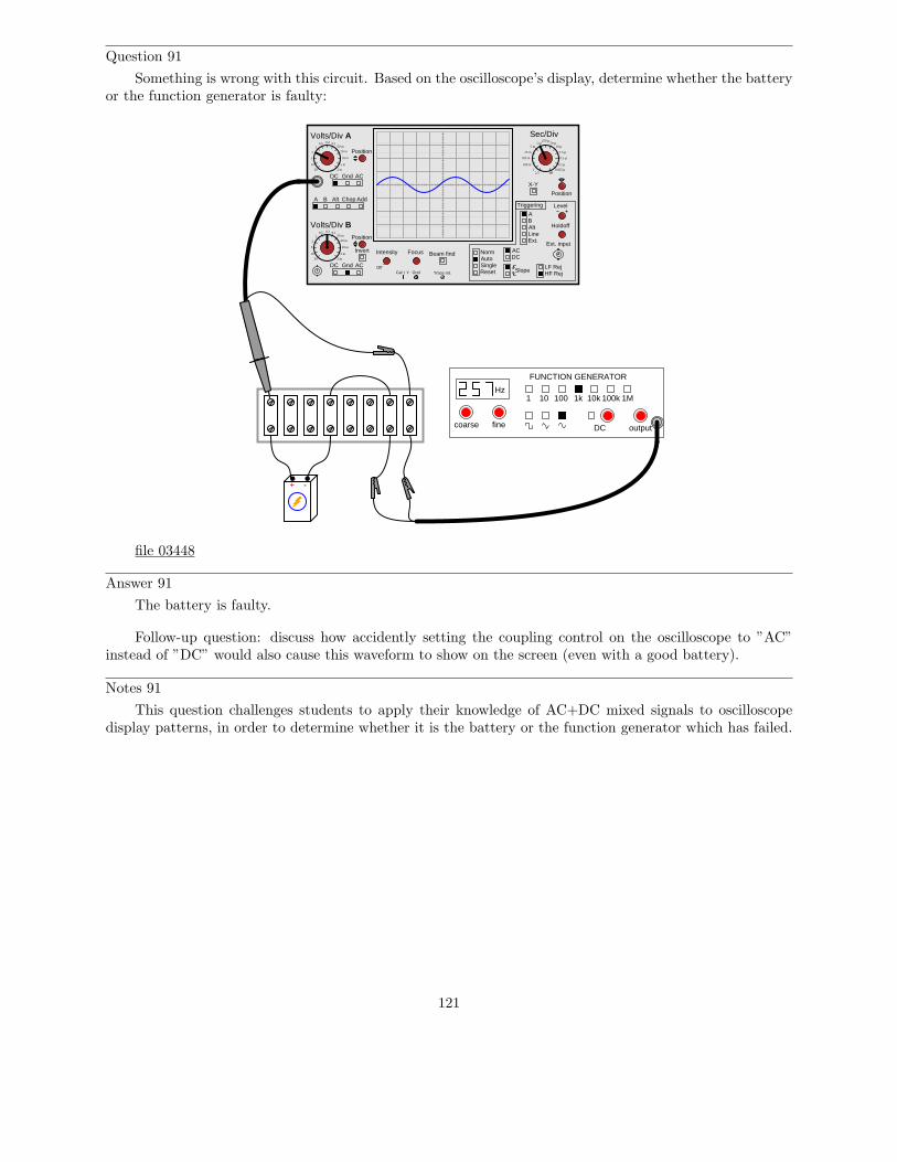
Question 91
Something is wrong with this circuit. Based on the oscilloscope’s display, determine whether the batteryor the function generator is faulty:
A B Alt Chop Add
Volts/Div A
Volts/Div B
DC Gnd AC
DC Gnd AC
Invert Intensity Focus
Position
Position
Position
Off
Beam find
LineExt.
AB
ACDC
NormAutoSingle
Slope
Level
Reset
X-Y
Holdoff
LF RejHF Rej
Triggering
Alt
Ext. input
Cal 1 V Gnd Trace rot.
Sec/Div0.5 0.2 0.1
1
10
5
2
20
50 m
20 m
10 m
5 m
2 m
0.5 0.2 0.11
10
5
2
20
50 m
20 m
10 m
5 m
2 m
1 m5 m
25 m
100 m
500 m
2.51
250 µ50 µ
10 µ
2.5 µ
0.5 µ
0.1 µ0.025 µ
off
Hz
FUNCTION GENERATOR
1 10 100 1k 10k 100k 1M
outputDCfinecoarse
+ -
file 03448
Answer 91
The battery is faulty.
Follow-up question: discuss how accidently setting the coupling control on the oscilloscope to ”AC”instead of ”DC” would also cause this waveform to show on the screen (even with a good battery).
Notes 91
This question challenges students to apply their knowledge of AC+DC mixed signals to oscilloscopedisplay patterns, in order to determine whether it is the battery or the function generator which has failed.
121
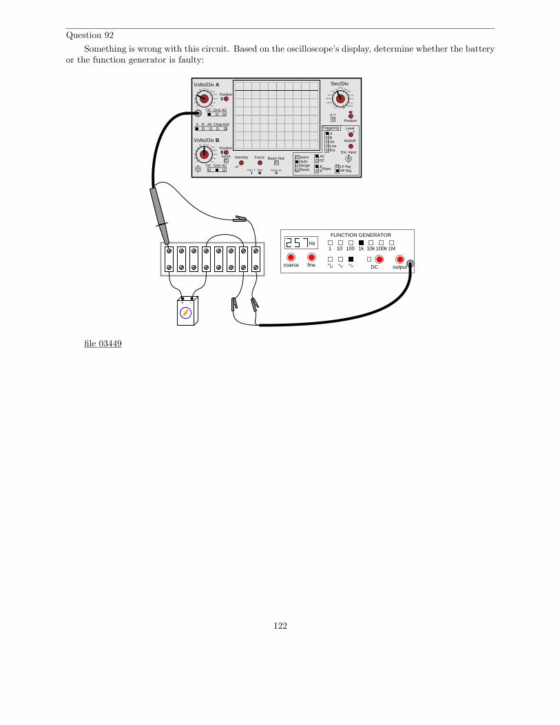
Question 92
Something is wrong with this circuit. Based on the oscilloscope’s display, determine whether the batteryor the function generator is faulty:
A B Alt Chop Add
Volts/Div A
Volts/Div B
DC Gnd AC
DC Gnd AC
Invert Intensity Focus
Position
Position
Position
Off
Beam find
LineExt.
AB
ACDC
NormAutoSingle
Slope
Level
Reset
X-Y
Holdoff
LF RejHF Rej
Triggering
Alt
Ext. input
Cal 1 V Gnd Trace rot.
Sec/Div0.5 0.2 0.1
1
10
5
2
20
50 m
20 m
10 m
5 m
2 m
0.5 0.2 0.11
10
5
2
20
50 m
20 m
10 m
5 m
2 m
1 m5 m
25 m
100 m
500 m
2.51
250 µ50 µ
10 µ
2.5 µ
0.5 µ
0.1 µ0.025 µ
off
Hz
FUNCTION GENERATOR
1 10 100 1k 10k 100k 1M
outputDCfinecoarse
+ -
file 03449
122
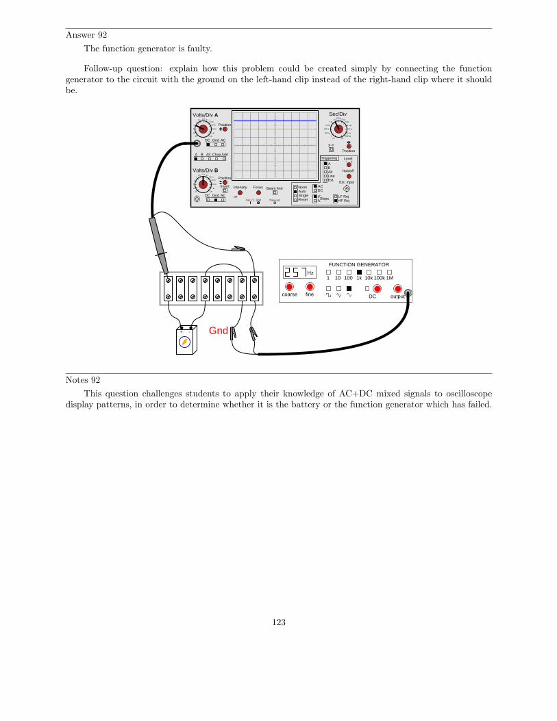
Answer 92
The function generator is faulty.
Follow-up question: explain how this problem could be created simply by connecting the functiongenerator to the circuit with the ground on the left-hand clip instead of the right-hand clip where it shouldbe.
A B Alt Chop Add
Volts/Div A
Volts/Div B
DC Gnd AC
DC Gnd AC
Invert Intensity Focus
Position
Position
Position
Off
Beam find
LineExt.
AB
ACDC
NormAutoSingle
Slope
Level
Reset
X-Y
Holdoff
LF RejHF Rej
Triggering
Alt
Ext. input
Cal 1 V Gnd Trace rot.
Sec/Div0.5 0.2 0.1
1
10
5
2
20
50 m
20 m
10 m
5 m
2 m
0.5 0.2 0.11
10
5
2
20
50 m
20 m
10 m
5 m
2 m
1 m5 m
25 m
100 m
500 m
2.51
250 µ50 µ
10 µ
2.5 µ
0.5 µ
0.1 µ0.025 µ
off
Hz
FUNCTION GENERATOR
1 10 100 1k 10k 100k 1M
outputDCfinecoarse
+ - Gnd
Notes 92
This question challenges students to apply their knowledge of AC+DC mixed signals to oscilloscopedisplay patterns, in order to determine whether it is the battery or the function generator which has failed.
123
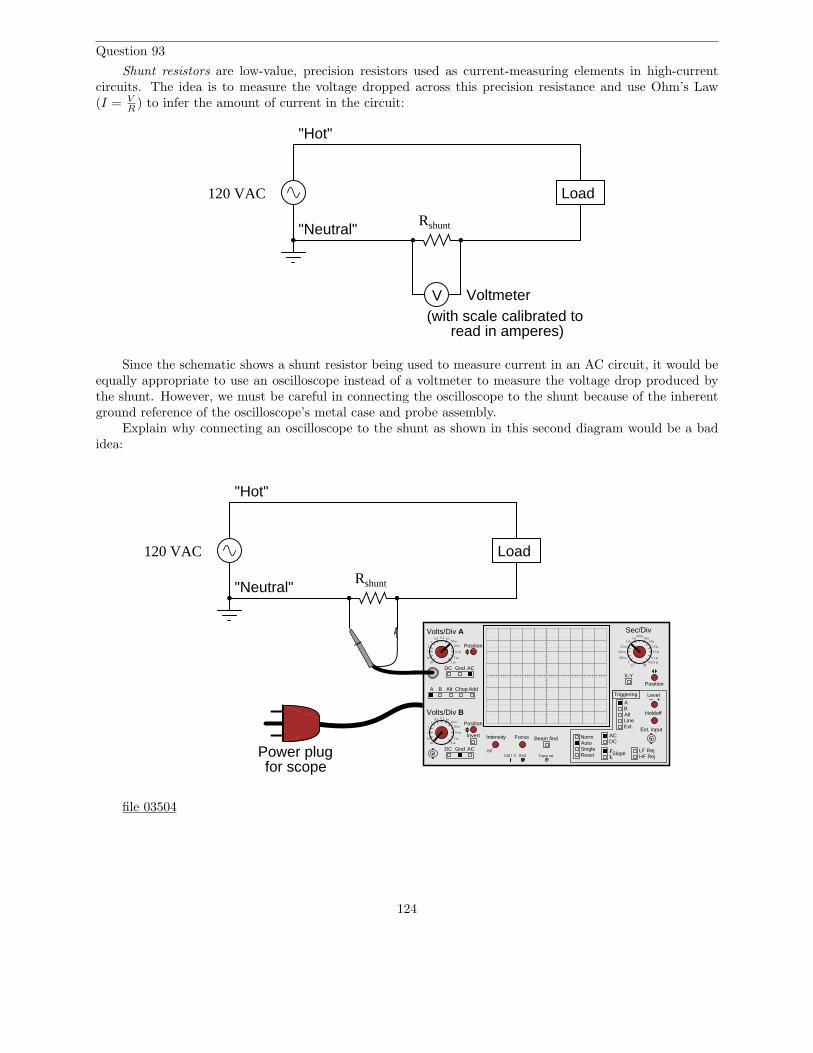
Question 93
Shunt resistors are low-value, precision resistors used as current-measuring elements in high-currentcircuits. The idea is to measure the voltage dropped across this precision resistance and use Ohm’s Law(I = V
R) to infer the amount of current in the circuit:
Load
Rshunt
120 VAC
"Hot"
"Neutral"
Voltmeter(with scale calibrated to
read in amperes)
V
Since the schematic shows a shunt resistor being used to measure current in an AC circuit, it would beequally appropriate to use an oscilloscope instead of a voltmeter to measure the voltage drop produced bythe shunt. However, we must be careful in connecting the oscilloscope to the shunt because of the inherentground reference of the oscilloscope’s metal case and probe assembly.
Explain why connecting an oscilloscope to the shunt as shown in this second diagram would be a badidea:
Load
Rshunt
120 VAC
"Hot"
"Neutral"
A B Alt Chop Add
Volts/Div A
Volts/Div B
DC Gnd AC
DC Gnd AC
Invert Intensity Focus
Position
Position
Position
Off
Beam find
LineExt.
AB
ACDC
NormAutoSingle
Slope
Level
Reset
X-Y
Holdoff
LF RejHF Rej
Triggering
Alt
Ext. input
Cal 1 V Gnd Trace rot.
Sec/Div0.5 0.2 0.1
1
10
5
2
20
50 m
20 m
10 m
5 m
2 m
0.5 0.2 0.11
10
5
2
20
50 m
20 m
10 m
5 m
2 m
1 m5 m
25 m
100 m
500 m
2.51
250 µ50 µ
10 µ
2.5 µ
0.5 µ
0.1 µ0.025 µ
off
Power plugfor scope
file 03504
124

Answer 93
This would be a bad idea because the oscilloscope’s ground clip would attempt to bypass current aroundthe shunt resistor, through the oscilloscope’s safety ground wire, and back to the grounded terminal of theAC source. Not only would this induce measurement errors, but it could damage the oscilloscope as well.
Follow-up question: identify a better way of connecting this oscilloscope to the shunt resistor.
125
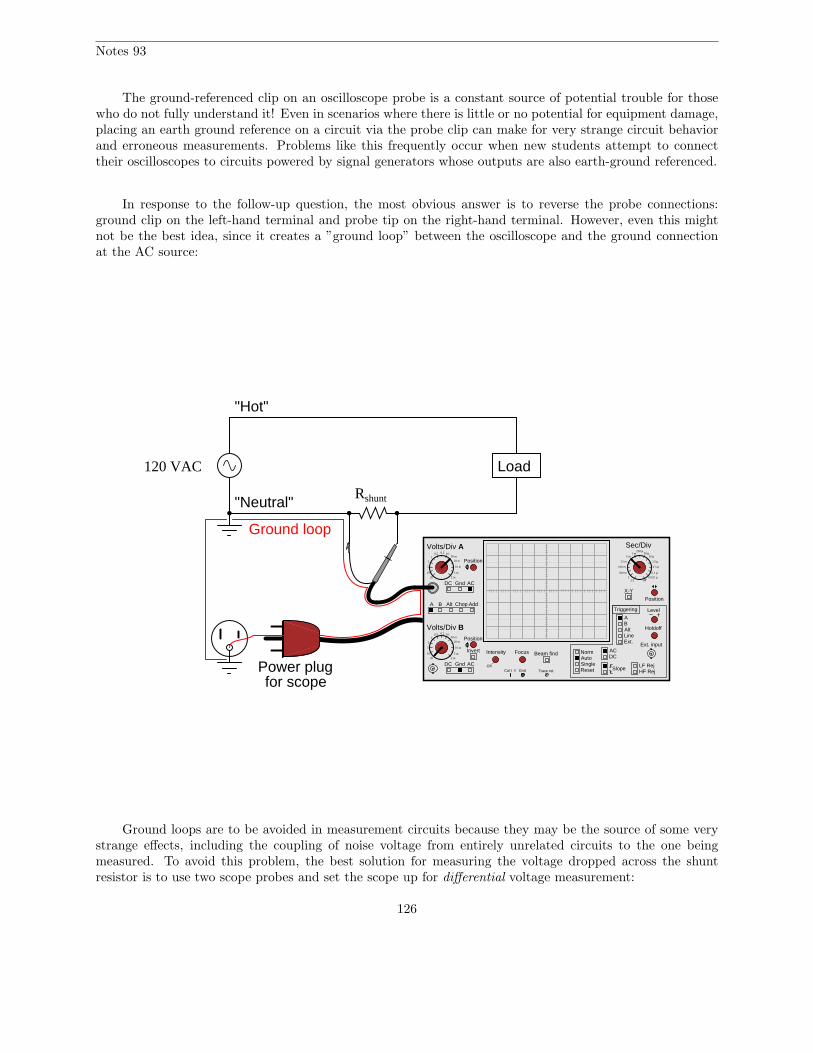
Notes 93
The ground-referenced clip on an oscilloscope probe is a constant source of potential trouble for thosewho do not fully understand it! Even in scenarios where there is little or no potential for equipment damage,placing an earth ground reference on a circuit via the probe clip can make for very strange circuit behaviorand erroneous measurements. Problems like this frequently occur when new students attempt to connecttheir oscilloscopes to circuits powered by signal generators whose outputs are also earth-ground referenced.
In response to the follow-up question, the most obvious answer is to reverse the probe connections:ground clip on the left-hand terminal and probe tip on the right-hand terminal. However, even this mightnot be the best idea, since it creates a ”ground loop” between the oscilloscope and the ground connectionat the AC source:
Load
Rshunt
120 VAC
"Hot"
"Neutral"
A B Alt Chop Add
Volts/Div A
Volts/Div B
DC Gnd AC
DC Gnd AC
Invert Intensity Focus
Position
Position
Position
Off
Beam find
LineExt.
AB
ACDC
NormAutoSingle
Slope
Level
Reset
X-Y
Holdoff
LF RejHF Rej
Triggering
Alt
Ext. input
Cal 1 V Gnd Trace rot.
Sec/Div0.5 0.2 0.1
1
10
5
2
20
50 m
20 m
10 m
5 m
2 m
0.5 0.2 0.11
10
5
2
20
50 m
20 m
10 m
5 m
2 m
1 m5 m
25 m
100 m
500 m
2.51
250 µ50 µ
10 µ
2.5 µ
0.5 µ
0.1 µ0.025 µ
off
Power plugfor scope
Ground loop
Ground loops are to be avoided in measurement circuits because they may be the source of some verystrange effects, including the coupling of noise voltage from entirely unrelated circuits to the one beingmeasured. To avoid this problem, the best solution for measuring the voltage dropped across the shuntresistor is to use two scope probes and set the scope up for differential voltage measurement:
126
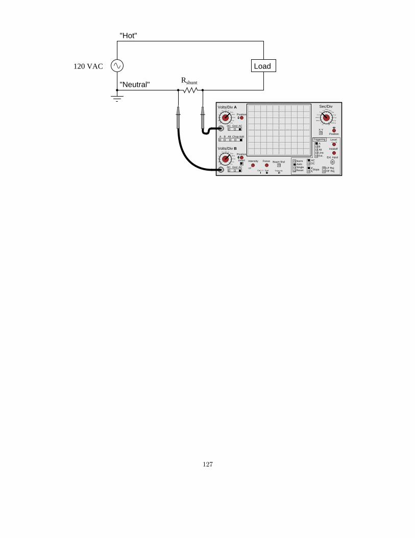
Load
Rshunt
120 VAC
"Hot"
"Neutral"
A B Alt Chop Add
Volts/Div A
Volts/Div B
DC Gnd AC
DC Gnd AC
Invert Intensity Focus
Position
Position
Position
Off
Beam find
LineExt.
AB
ACDC
NormAutoSingle
Slope
Level
Reset
X-Y
Holdoff
LF RejHF Rej
Triggering
Alt
Ext. input
Cal 1 V Gnd Trace rot.
Sec/Div0.5 0.2 0.1
1
10
5
2
20
50 m
20 m
10 m
5 m
2 m
0.5 0.2 0.11
10
5
2
20
50 m
20 m
10 m
5 m
2 m
1 m5 m
25 m
100 m
500 m
2.51
250 µ50 µ
10 µ
2.5 µ
0.5 µ
0.1 µ0.025 µ
off
127
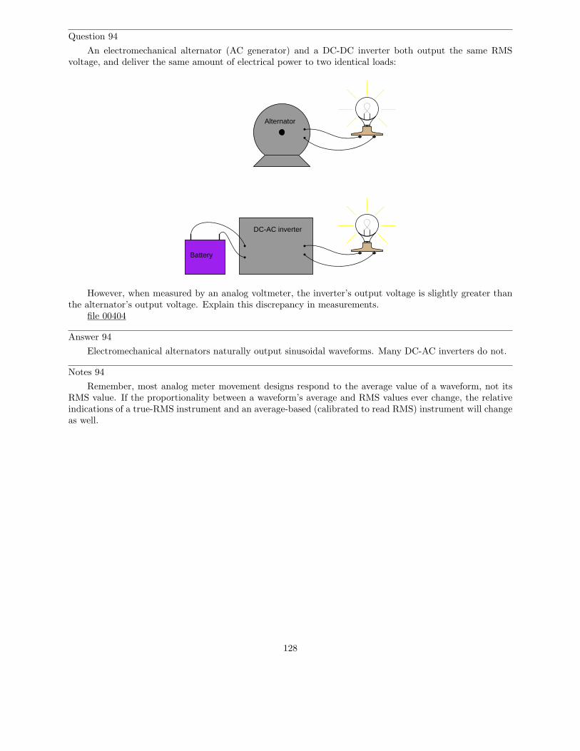
Question 94
An electromechanical alternator (AC generator) and a DC-DC inverter both output the same RMSvoltage, and deliver the same amount of electrical power to two identical loads:
Alternator
DC-AC inverter
Battery
However, when measured by an analog voltmeter, the inverter’s output voltage is slightly greater thanthe alternator’s output voltage. Explain this discrepancy in measurements.
file 00404
Answer 94
Electromechanical alternators naturally output sinusoidal waveforms. Many DC-AC inverters do not.
Notes 94
Remember, most analog meter movement designs respond to the average value of a waveform, not itsRMS value. If the proportionality between a waveform’s average and RMS values ever change, the relativeindications of a true-RMS instrument and an average-based (calibrated to read RMS) instrument will changeas well.
128

Question 95
Is the deflection of an analog AC meter movement proportional to the peak, average, or RMS value ofthe waveform measured? Explain your answer.
file 00403
Answer 95
Analog meter deflection is proportional to the average value of the AC waveform measured, for most ACmeter movement types. There are some meter movement designs, however, that give indications proportionalto the RMS value of the waveform: hot-wire and electrodynamometer movements are of this nature.
Follow-up question: does this mean an average-responding meter movement cannot be calibrated toindicate in RMS units?
Challenge question: why do hot-wire and electrodynamometer meter movements provide true RMSindications, while most other movement designs indicate based on the signal’s average value?
Notes 95
Students often confuse the terms ”average” and ”RMS”, thinking they are interchangeable. Discussthe difference between these two terms, both mathematically and practically. While the concepts may seemsimilar at first, the details are actually quite different.
The question of whether an average-responding instrument can be calibrated to register in RMS unitsis very practical, since the vast majority of multimeters are calibrated this way. Because the proportionalitybetween the average and RMS values of an AC waveform are dependent on the shape of the waveform, acertain wave-shape must be assumed in order to accurately calibrate an average-responding meter movementfor RMS measurement. The assumed wave-shape, of course, is sinusoidal.
129

Question 96
In calculating the size of wire necessary to carry alternating current to a high-power load, which typeof measurement is the best to use for current: peak, average, or RMS? Explain why.
file 00162
Answer 96
RMS current is the most appropriate type of measurement for calculating wire size.
Notes 96
A clue to answering this question is this: what actually happens when the ampacity rating of a conductoris exceeded? Why, exactly, is overcurrent a bad thing for conductors in general?
It is important for students to recognize the value of RMS measurements: why do we use them, and inwhat applications are they the most appropriate type of measurement to use in certain calculations? Askyour students what other applications might best use RMS voltage and current measurements as opposedto peak or average.
130
Question 97
In calculating the thickness of insulators for high-voltage AC power lines, which type of measurementis the best to use for voltage: peak, average, or RMS? Explain why.
file 00163
Answer 97
Peak voltage is the most appropriate type of measurement for calculating insulator thickness. Thereason why has to do with the time required for an insulator to ”flash over.”
Notes 97
A closely related subject is insulator breakdown, or dielectric strength. What actually happens when thedielectric strength rating of an insulator is exceeded?
131
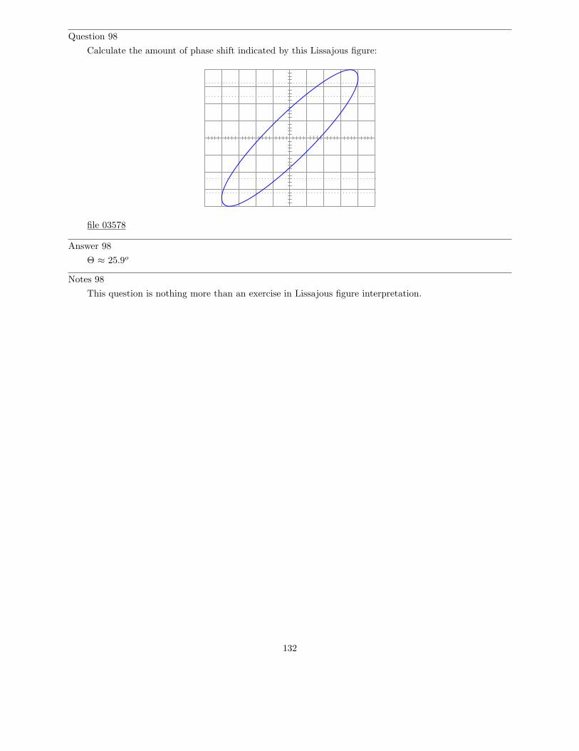
Question 98
Calculate the amount of phase shift indicated by this Lissajous figure:
file 03578
Answer 98
Θ ≈ 25.9o
Notes 98
This question is nothing more than an exercise in Lissajous figure interpretation.
132
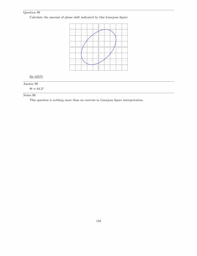
Question 99
Calculate the amount of phase shift indicated by this Lissajous figure:
file 03575
Answer 99
Θ ≈ 64.2o
Notes 99
This question is nothing more than an exercise in Lissajous figure interpretation.
133
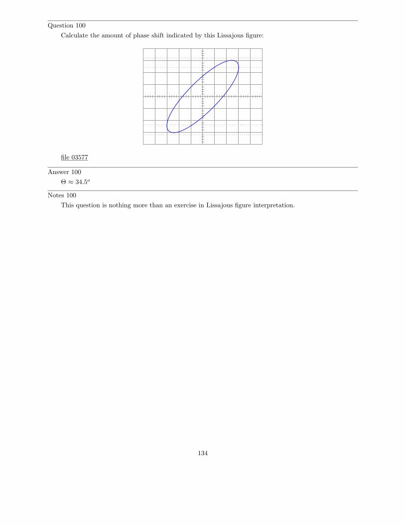
Question 100
Calculate the amount of phase shift indicated by this Lissajous figure:
file 03577
Answer 100
Θ ≈ 34.5o
Notes 100
This question is nothing more than an exercise in Lissajous figure interpretation.
134
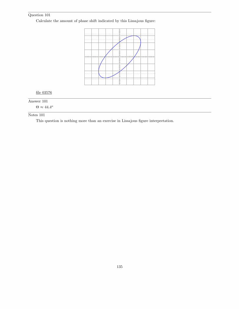
Question 101
Calculate the amount of phase shift indicated by this Lissajous figure:
file 03576
Answer 101
Θ ≈ 44.4o
Notes 101
This question is nothing more than an exercise in Lissajous figure interpretation.
135
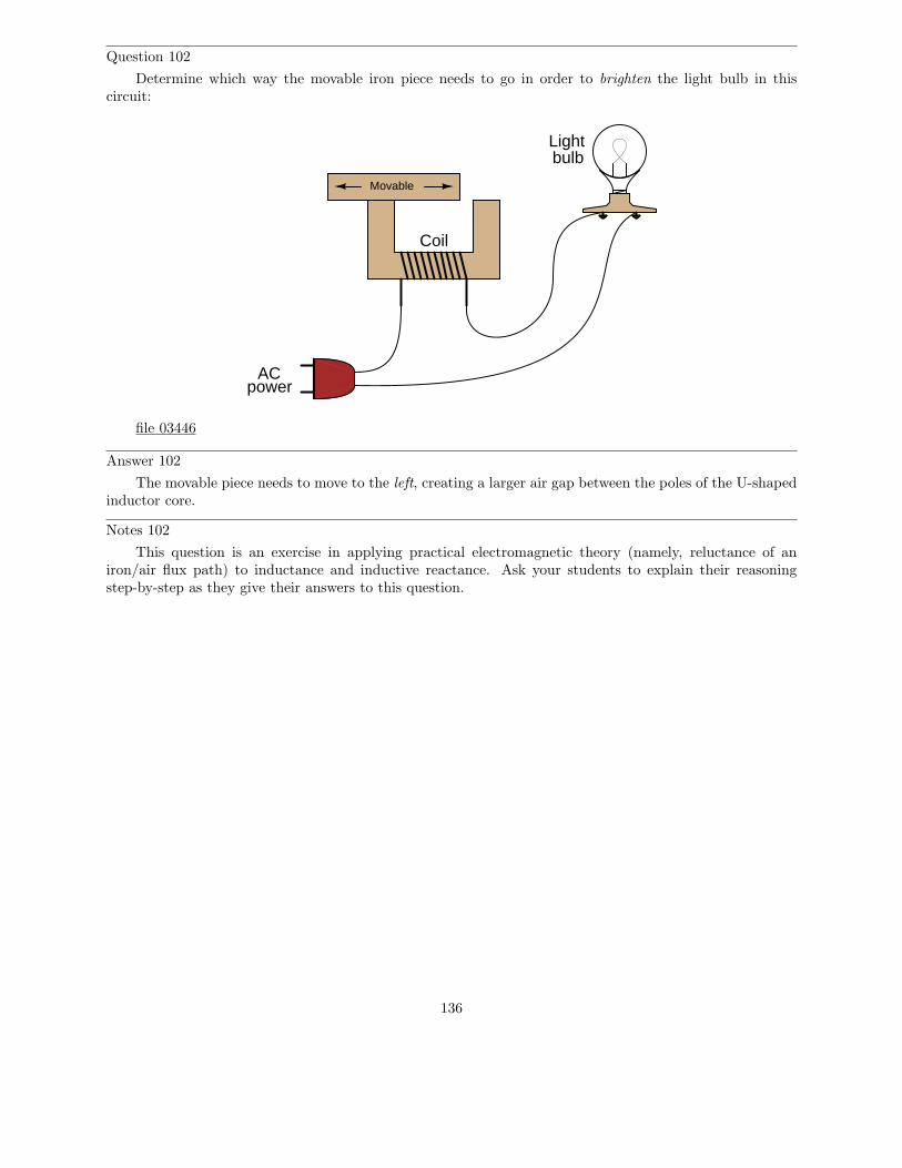
Question 102
Determine which way the movable iron piece needs to go in order to brighten the light bulb in thiscircuit:
Movable
ACpower
Lightbulb
Coil
file 03446
Answer 102
The movable piece needs to move to the left, creating a larger air gap between the poles of the U-shapedinductor core.
Notes 102
This question is an exercise in applying practical electromagnetic theory (namely, reluctance of aniron/air flux path) to inductance and inductive reactance. Ask your students to explain their reasoningstep-by-step as they give their answers to this question.
136
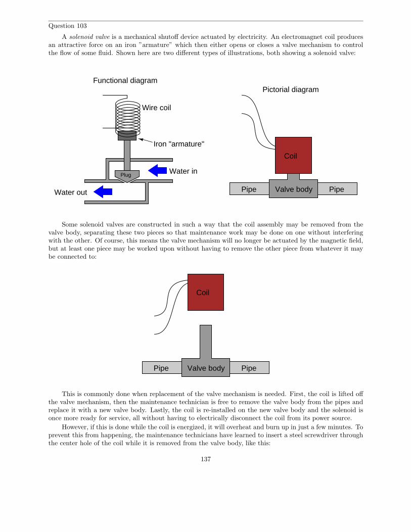
Question 103
A solenoid valve is a mechanical shutoff device actuated by electricity. An electromagnet coil producesan attractive force on an iron ”armature” which then either opens or closes a valve mechanism to controlthe flow of some fluid. Shown here are two different types of illustrations, both showing a solenoid valve:
Plug
Wire coil
Iron "armature"
Water in
PipePipe
Functional diagramPictorial diagram
Coil
Valve bodyWater out
Some solenoid valves are constructed in such a way that the coil assembly may be removed from thevalve body, separating these two pieces so that maintenance work may be done on one without interferingwith the other. Of course, this means the valve mechanism will no longer be actuated by the magnetic field,but at least one piece may be worked upon without having to remove the other piece from whatever it maybe connected to:
PipePipe
Coil
Valve body
This is commonly done when replacement of the valve mechanism is needed. First, the coil is lifted offthe valve mechanism, then the maintenance technician is free to remove the valve body from the pipes andreplace it with a new valve body. Lastly, the coil is re-installed on the new valve body and the solenoid isonce more ready for service, all without having to electrically disconnect the coil from its power source.
However, if this is done while the coil is energized, it will overheat and burn up in just a few minutes. Toprevent this from happening, the maintenance technicians have learned to insert a steel screwdriver throughthe center hole of the coil while it is removed from the valve body, like this:
137
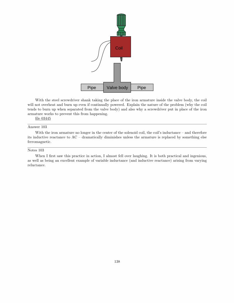
PipePipe Valve body
Coil
With the steel screwdriver shank taking the place of the iron armature inside the valve body, the coilwill not overheat and burn up even if continually powered. Explain the nature of the problem (why the coiltends to burn up when separated from the valve body) and also why a screwdriver put in place of the ironarmature works to prevent this from happening.
file 03445
Answer 103
With the iron armature no longer in the center of the solenoid coil, the coil’s inductance – and thereforeits inductive reactance to AC – dramatically diminishes unless the armature is replaced by something elseferromagnetic.
Notes 103
When I first saw this practice in action, I almost fell over laughing. It is both practical and ingenious,as well as being an excellent example of variable inductance (and inductive reactance) arising from varyingreluctance.
138
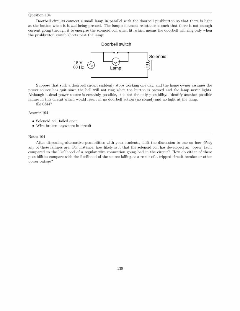
Question 104
Doorbell circuits connect a small lamp in parallel with the doorbell pushbutton so that there is lightat the button when it is not being pressed. The lamp’s filament resistance is such that there is not enoughcurrent going through it to energize the solenoid coil when lit, which means the doorbell will ring only whenthe pushbutton switch shorts past the lamp:
60 Hz18 V
Doorbell switch
Solenoid
Lamp
Suppose that such a doorbell circuit suddenly stops working one day, and the home owner assumes thepower source has quit since the bell will not ring when the button is pressed and the lamp never lights.Although a dead power source is certainly possible, it is not the only possibility. Identify another possiblefailure in this circuit which would result in no doorbell action (no sound) and no light at the lamp.
file 03447
Answer 104
• Solenoid coil failed open• Wire broken anywhere in circuit
Notes 104
After discussing alternative possibilities with your students, shift the discussion to one on how likelyany of these failures are. For instance, how likely is it that the solenoid coil has developed an ”open” faultcompared to the likelihood of a regular wire connection going bad in the circuit? How do either of thesepossibilities compare with the likelihood of the source failing as a result of a tripped circuit breaker or otherpower outage?
139

Question 105
Suppose someone were to ask you to differentiate electrical reactance (X) from electrical resistance (R).How would you distinguish these two similar concepts from one another, using your own words?
file 03301
Answer 105
It is really important for you to frame this concept in your own words, so be sure to check with yourinstructor on the accuracy of your answer to this question! To give you a place to start, I offer this distinction:resistance is electrical friction, whereas reactance is electrical energy storage. Fundamentally, the differencebetween X and R is a matter of energy exchange, and it is understood most accurately in those terms.
Notes 105
This is an excellent point of crossover with your students’ studies in elementary physics, if they arestudying physics now or have studied physics in the past. The energy-storing actions of inductors andcapacitors are quite analogous to the energy-storing actions of masses and springs (respectively, if youassociate velocity with current and force with voltage). In the same vein, resistance is analogous to kineticfriction between a moving object and a stationary surface. The parallels are so accurate, in fact, that theelectrical properties of R, L, and C have been exploited to model mechanical systems of friction, mass, andresilience in circuits known as analog computers.
140
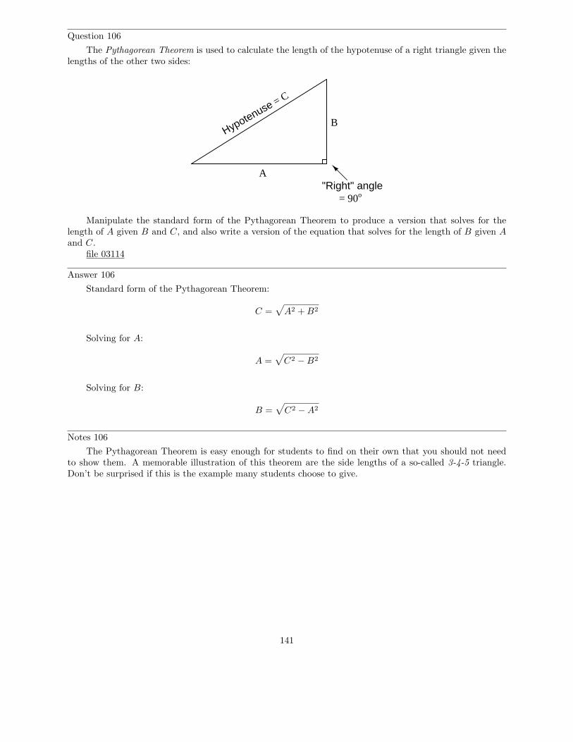
Question 106
The Pythagorean Theorem is used to calculate the length of the hypotenuse of a right triangle given thelengths of the other two sides:
Hypotenuse = C
A
B
"Right" angle= 90o
Manipulate the standard form of the Pythagorean Theorem to produce a version that solves for thelength of A given B and C, and also write a version of the equation that solves for the length of B given A
and C.file 03114
Answer 106
Standard form of the Pythagorean Theorem:
C =√
A2 + B2
Solving for A:
A =√
C2 − B2
Solving for B:
B =√
C2 − A2
Notes 106
The Pythagorean Theorem is easy enough for students to find on their own that you should not needto show them. A memorable illustration of this theorem are the side lengths of a so-called 3-4-5 triangle.Don’t be surprised if this is the example many students choose to give.
141
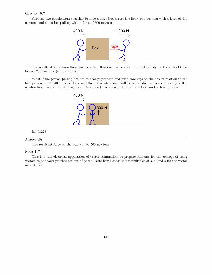
Question 107
Suppose two people work together to slide a large box across the floor, one pushing with a force of 400newtons and the other pulling with a force of 300 newtons:
Box rope
400 N 300 N
The resultant force from these two persons’ efforts on the box will, quite obviously, be the sum of theirforces: 700 newtons (to the right).
What if the person pulling decides to change position and push sideways on the box in relation to thefirst person, so the 400 newton force and the 300 newton force will be perpendicular to each other (the 300newton force facing into the page, away from you)? What will the resultant force on the box be then?
400 N
300 N
file 03278
Answer 107
The resultant force on the box will be 500 newtons.
Notes 107
This is a non-electrical application of vector summation, to prepare students for the concept of usingvectors to add voltages that are out-of-phase. Note how I chose to use multiples of 3, 4, and 5 for the vectormagnitudes.
142
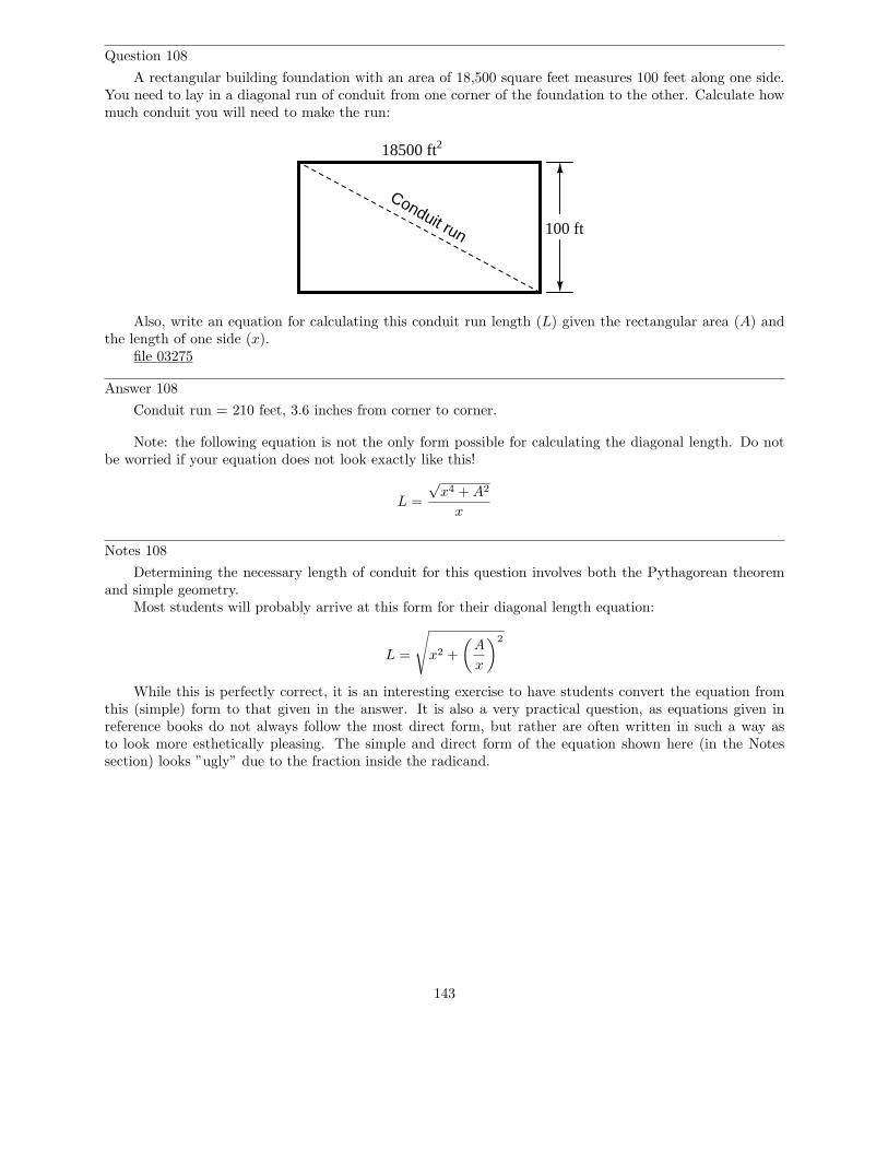
Question 108
A rectangular building foundation with an area of 18,500 square feet measures 100 feet along one side.You need to lay in a diagonal run of conduit from one corner of the foundation to the other. Calculate howmuch conduit you will need to make the run:
100 ft
18500 ft2
Conduit run
Also, write an equation for calculating this conduit run length (L) given the rectangular area (A) andthe length of one side (x).
file 03275
Answer 108
Conduit run = 210 feet, 3.6 inches from corner to corner.
Note: the following equation is not the only form possible for calculating the diagonal length. Do notbe worried if your equation does not look exactly like this!
L =
√x4 + A2
x
Notes 108
Determining the necessary length of conduit for this question involves both the Pythagorean theoremand simple geometry.
Most students will probably arrive at this form for their diagonal length equation:
L =
√
x2 +
(
A
x
)2
While this is perfectly correct, it is an interesting exercise to have students convert the equation fromthis (simple) form to that given in the answer. It is also a very practical question, as equations given inreference books do not always follow the most direct form, but rather are often written in such a way asto look more esthetically pleasing. The simple and direct form of the equation shown here (in the Notessection) looks ”ugly” due to the fraction inside the radicand.
143
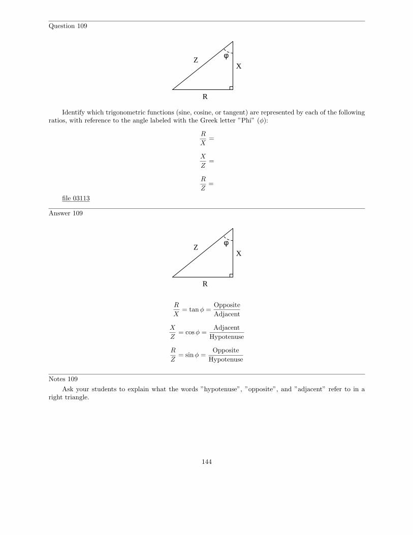
Question 109
Z
R
X
φ
Identify which trigonometric functions (sine, cosine, or tangent) are represented by each of the followingratios, with reference to the angle labeled with the Greek letter ”Phi” (φ):
R
X=
X
Z=
R
Z=
file 03113
Answer 109
Z
R
X
φ
R
X= tanφ =
Opposite
Adjacent
X
Z= cos φ =
Adjacent
Hypotenuse
R
Z= sin φ =
Opposite
Hypotenuse
Notes 109
Ask your students to explain what the words ”hypotenuse”, ”opposite”, and ”adjacent” refer to in aright triangle.
144
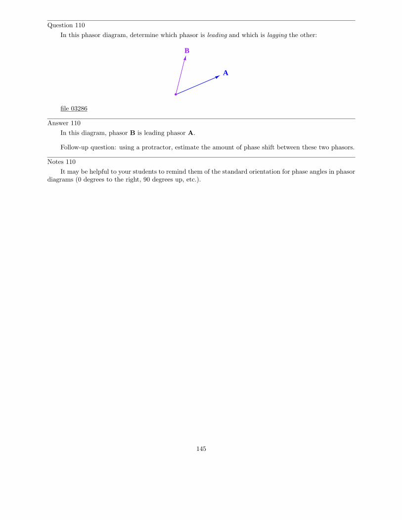
Question 110
In this phasor diagram, determine which phasor is leading and which is lagging the other:
A
B
file 03286
Answer 110
In this diagram, phasor B is leading phasor A.
Follow-up question: using a protractor, estimate the amount of phase shift between these two phasors.
Notes 110
It may be helpful to your students to remind them of the standard orientation for phase angles in phasordiagrams (0 degrees to the right, 90 degrees up, etc.).
145
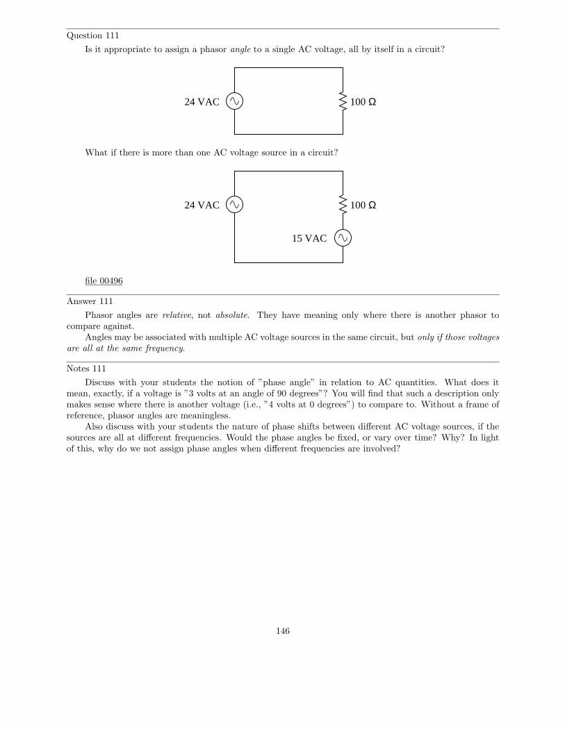
Question 111
Is it appropriate to assign a phasor angle to a single AC voltage, all by itself in a circuit?
24 VAC 100 Ω
What if there is more than one AC voltage source in a circuit?
24 VAC 100 Ω
15 VAC
file 00496
Answer 111
Phasor angles are relative, not absolute. They have meaning only where there is another phasor tocompare against.
Angles may be associated with multiple AC voltage sources in the same circuit, but only if those voltagesare all at the same frequency.
Notes 111
Discuss with your students the notion of ”phase angle” in relation to AC quantities. What does itmean, exactly, if a voltage is ”3 volts at an angle of 90 degrees”? You will find that such a description onlymakes sense where there is another voltage (i.e., ”4 volts at 0 degrees”) to compare to. Without a frame ofreference, phasor angles are meaningless.
Also discuss with your students the nature of phase shifts between different AC voltage sources, if thesources are all at different frequencies. Would the phase angles be fixed, or vary over time? Why? In lightof this, why do we not assign phase angles when different frequencies are involved?
146
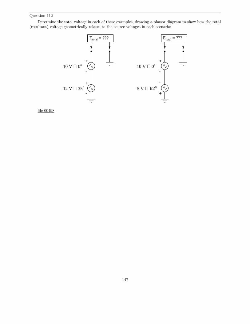
Question 112
Determine the total voltage in each of these examples, drawing a phasor diagram to show how the total(resultant) voltage geometrically relates to the source voltages in each scenario:
12 V ∠ 35o
10 V ∠ 0o+
-
+
-
Etotal = ???
10 V ∠ 0o+
-
+
-
Etotal = ???
5 V ∠ 62o
file 00498
147
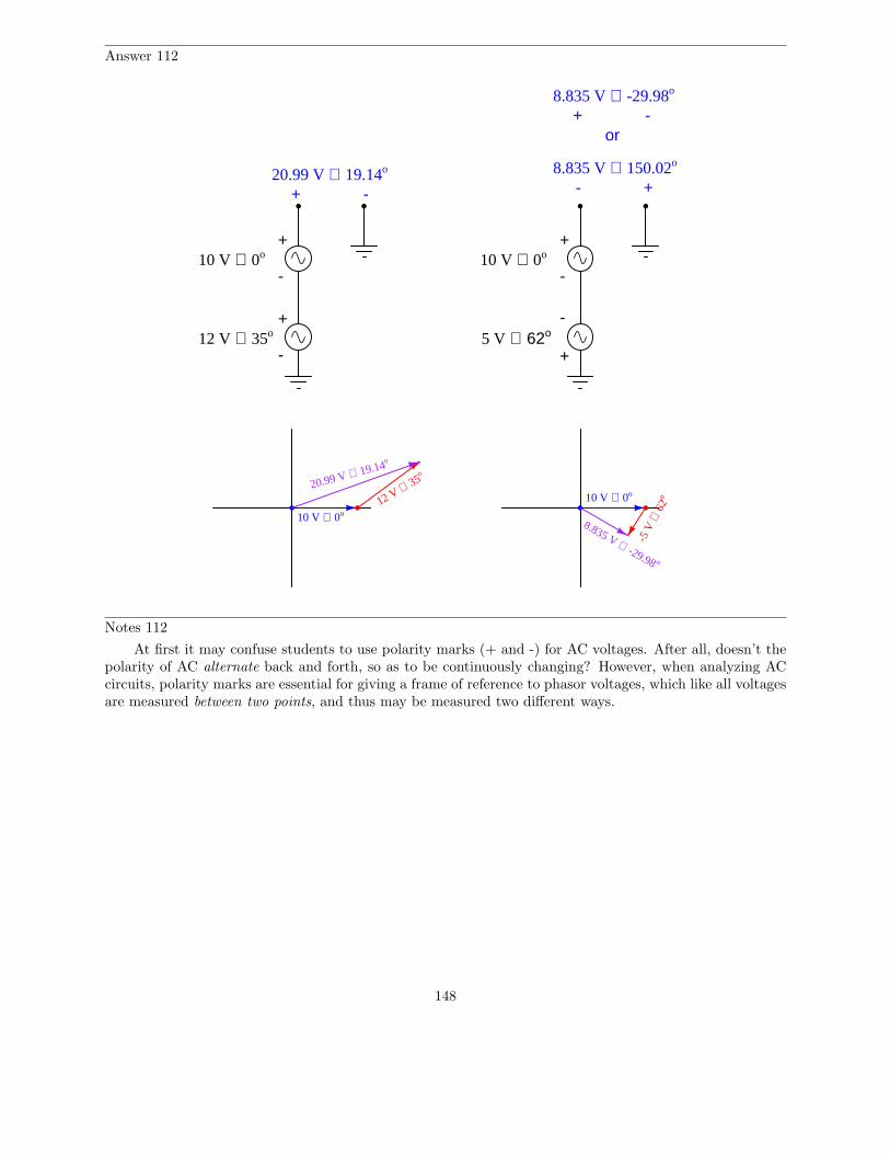
Answer 112
12 V ∠ 35o
10 V ∠ 0o+
-
+
-
10 V ∠ 0o+
-
+
-5 V ∠ 62o
20.99 V ∠ 19.14o
+ -
8.835 V ∠ -29.98o
+ -or
8.835 V ∠ 150.02o
+-
10 V ∠ 0o12 V ∠ 35
o
20.99 V ∠ 19.14o
10 V ∠ 0o
-5 V
∠ 6
2o
8.835 V ∠ -29.98 o
Notes 112
At first it may confuse students to use polarity marks (+ and -) for AC voltages. After all, doesn’t thepolarity of AC alternate back and forth, so as to be continuously changing? However, when analyzing ACcircuits, polarity marks are essential for giving a frame of reference to phasor voltages, which like all voltagesare measured between two points, and thus may be measured two different ways.
148
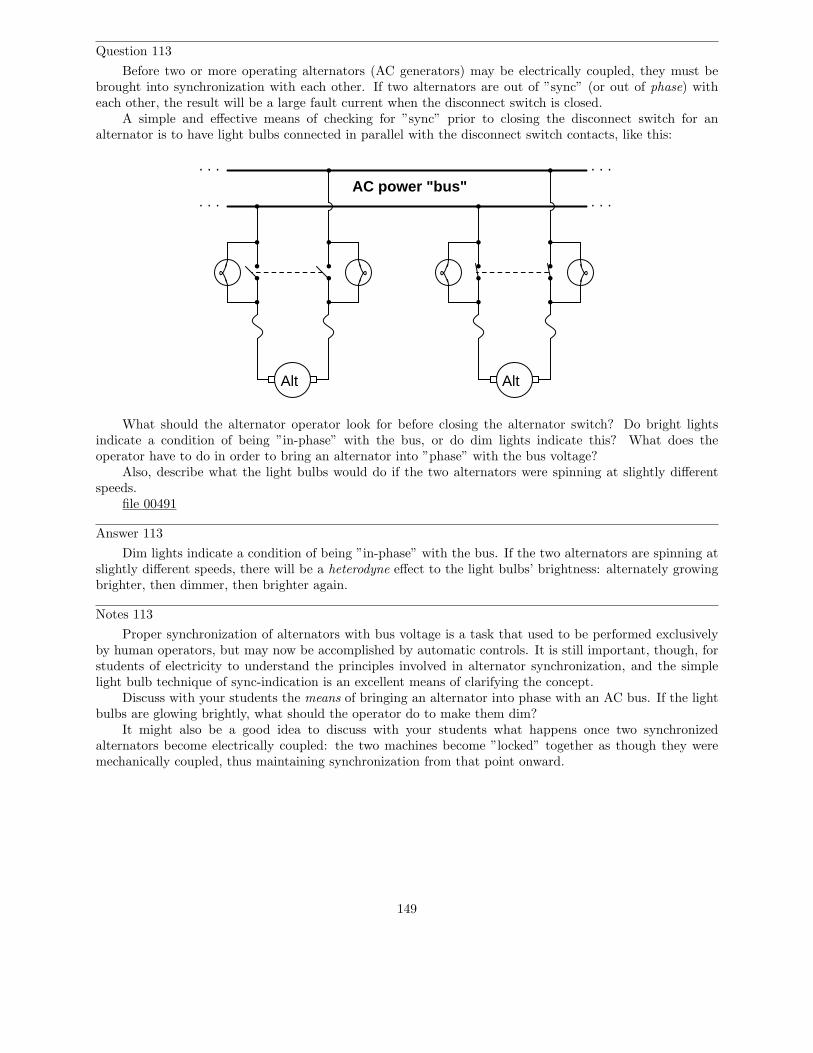
Question 113
Before two or more operating alternators (AC generators) may be electrically coupled, they must bebrought into synchronization with each other. If two alternators are out of ”sync” (or out of phase) witheach other, the result will be a large fault current when the disconnect switch is closed.
A simple and effective means of checking for ”sync” prior to closing the disconnect switch for analternator is to have light bulbs connected in parallel with the disconnect switch contacts, like this:
. . .. . .
. . .. . .
Alt
AC power "bus"
Alt
What should the alternator operator look for before closing the alternator switch? Do bright lightsindicate a condition of being ”in-phase” with the bus, or do dim lights indicate this? What does theoperator have to do in order to bring an alternator into ”phase” with the bus voltage?
Also, describe what the light bulbs would do if the two alternators were spinning at slightly differentspeeds.
file 00491
Answer 113
Dim lights indicate a condition of being ”in-phase” with the bus. If the two alternators are spinning atslightly different speeds, there will be a heterodyne effect to the light bulbs’ brightness: alternately growingbrighter, then dimmer, then brighter again.
Notes 113
Proper synchronization of alternators with bus voltage is a task that used to be performed exclusivelyby human operators, but may now be accomplished by automatic controls. It is still important, though, forstudents of electricity to understand the principles involved in alternator synchronization, and the simplelight bulb technique of sync-indication is an excellent means of clarifying the concept.
Discuss with your students the means of bringing an alternator into phase with an AC bus. If the lightbulbs are glowing brightly, what should the operator do to make them dim?
It might also be a good idea to discuss with your students what happens once two synchronizedalternators become electrically coupled: the two machines become ”locked” together as though they weremechanically coupled, thus maintaining synchronization from that point onward.
149
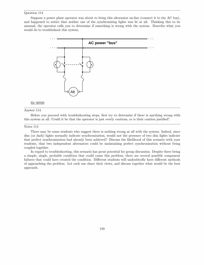
Question 114
Suppose a power plant operator was about to bring this alternator on-line (connect it to the AC bus),and happened to notice that neither one of the synchronizing lights was lit at all. Thinking this to beunusual, the operator calls you to determine if something is wrong with the system. Describe what youwould do to troubleshoot this system.
. . .. . .
. . .. . .
Alt
AC power "bus"
file 00500
Answer 114
Before you proceed with troubleshooting steps, first try to determine if there is anything wrong withthis system at all. Could it be that the operator is just overly cautious, or is their caution justified?
Notes 114
There may be some students who suggest there is nothing wrong at all with the system. Indeed, sincedim (or dark) lights normally indicate synchronization, would not the presence of two dim lights indicatethat perfect synchronization had already been achieved? Discuss the likelihood of this scenario with yourstudents, that two independent alternators could be maintaining perfect synchronization without beingcoupled together.
In regard to troubleshooting, this scenario has great potential for group discussion. Despite there beinga simple, single, probable condition that could cause this problem, there are several possible componentfailures that could have created the condition. Different students will undoubtedly have different methodsof approaching the problem. Let each one share their views, and discuss together what would be the bestapproach.
150
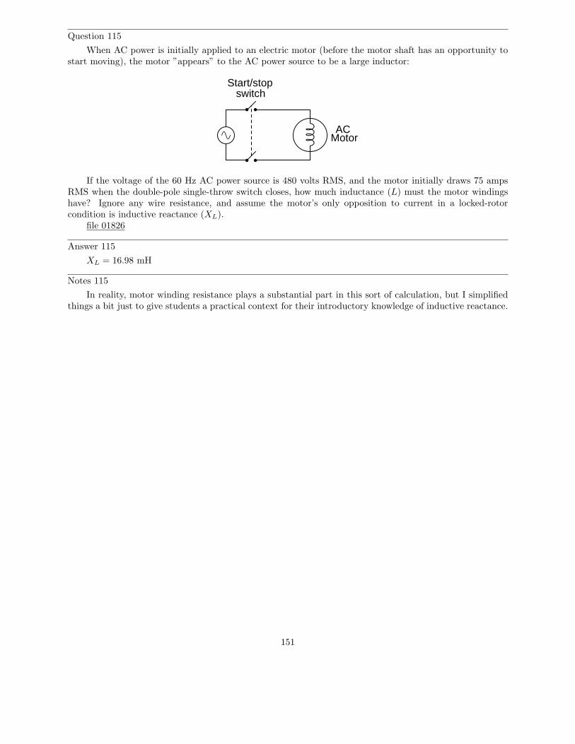
Question 115
When AC power is initially applied to an electric motor (before the motor shaft has an opportunity tostart moving), the motor ”appears” to the AC power source to be a large inductor:
Start/stopswitch
MotorAC
If the voltage of the 60 Hz AC power source is 480 volts RMS, and the motor initially draws 75 ampsRMS when the double-pole single-throw switch closes, how much inductance (L) must the motor windingshave? Ignore any wire resistance, and assume the motor’s only opposition to current in a locked-rotorcondition is inductive reactance (XL).
file 01826
Answer 115
XL = 16.98 mH
Notes 115
In reality, motor winding resistance plays a substantial part in this sort of calculation, but I simplifiedthings a bit just to give students a practical context for their introductory knowledge of inductive reactance.
151
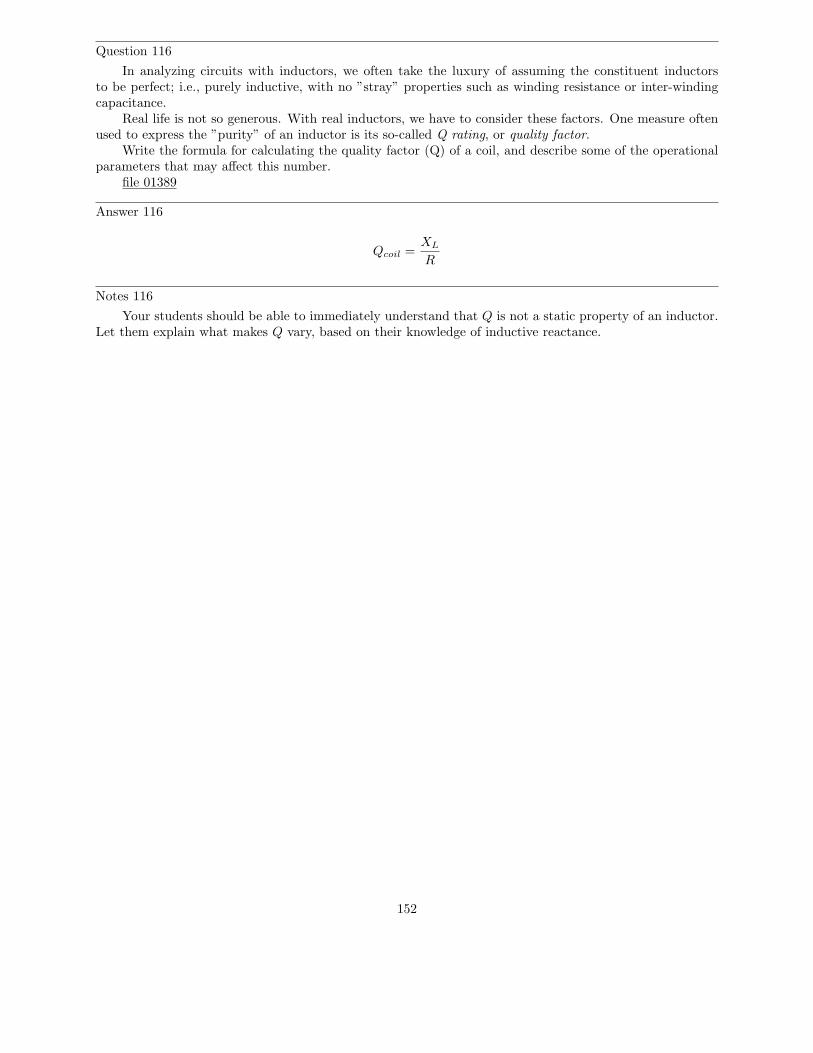
Question 116
In analyzing circuits with inductors, we often take the luxury of assuming the constituent inductorsto be perfect; i.e., purely inductive, with no ”stray” properties such as winding resistance or inter-windingcapacitance.
Real life is not so generous. With real inductors, we have to consider these factors. One measure oftenused to express the ”purity” of an inductor is its so-called Q rating, or quality factor.
Write the formula for calculating the quality factor (Q) of a coil, and describe some of the operationalparameters that may affect this number.
file 01389
Answer 116
Qcoil =XL
R
Notes 116
Your students should be able to immediately understand that Q is not a static property of an inductor.Let them explain what makes Q vary, based on their knowledge of inductive reactance.
152
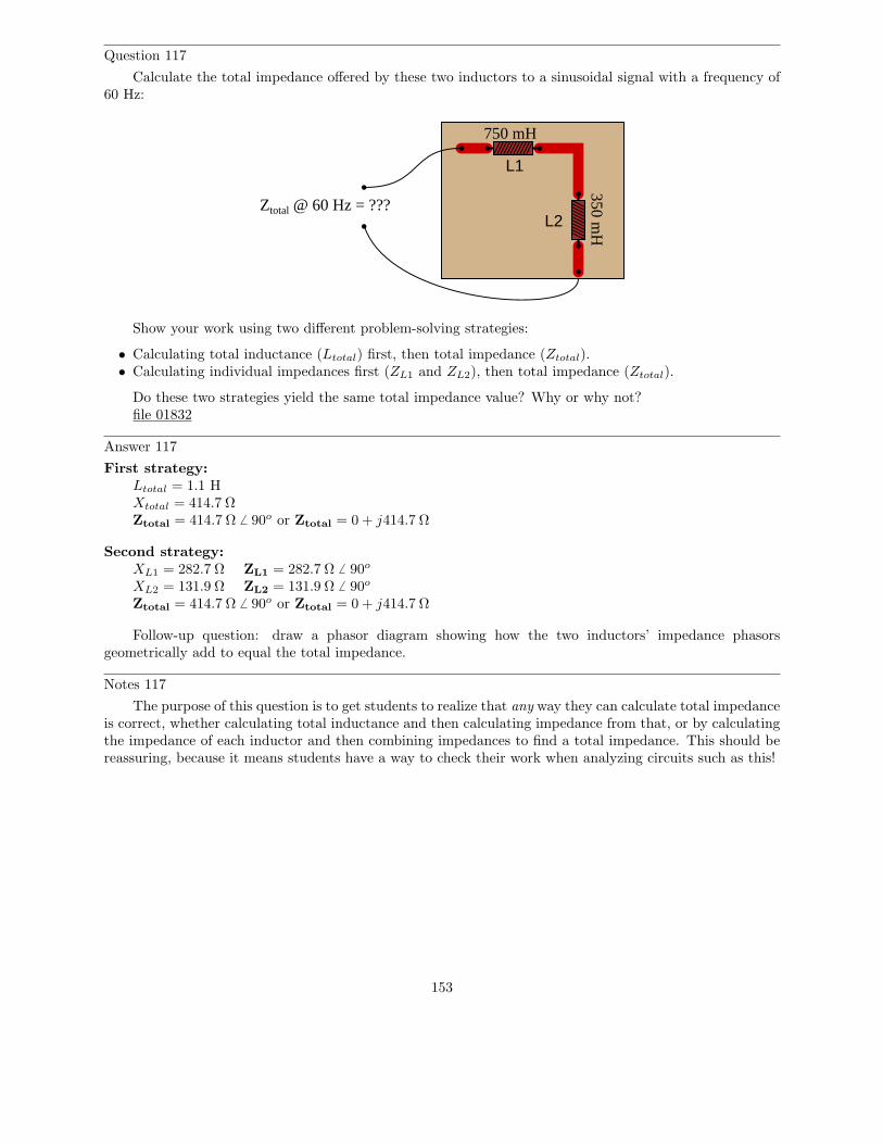
Question 117
Calculate the total impedance offered by these two inductors to a sinusoidal signal with a frequency of60 Hz:
L1
L2
750 mH
350 mH
Ztotal @ 60 Hz = ???
Show your work using two different problem-solving strategies:
• Calculating total inductance (Ltotal) first, then total impedance (Ztotal).• Calculating individual impedances first (ZL1 and ZL2), then total impedance (Ztotal).
Do these two strategies yield the same total impedance value? Why or why not?file 01832
Answer 117
First strategy:Ltotal = 1.1 HXtotal = 414.7 ΩZtotal = 414.7 Ω 6 90o or Ztotal = 0 + j414.7 Ω
Second strategy:XL1 = 282.7 Ω ZL1 = 282.7 Ω 6 90o
XL2 = 131.9 Ω ZL2 = 131.9 Ω 6 90o
Ztotal = 414.7 Ω 6 90o or Ztotal = 0 + j414.7 Ω
Follow-up question: draw a phasor diagram showing how the two inductors’ impedance phasorsgeometrically add to equal the total impedance.
Notes 117
The purpose of this question is to get students to realize that any way they can calculate total impedanceis correct, whether calculating total inductance and then calculating impedance from that, or by calculatingthe impedance of each inductor and then combining impedances to find a total impedance. This should bereassuring, because it means students have a way to check their work when analyzing circuits such as this!
153
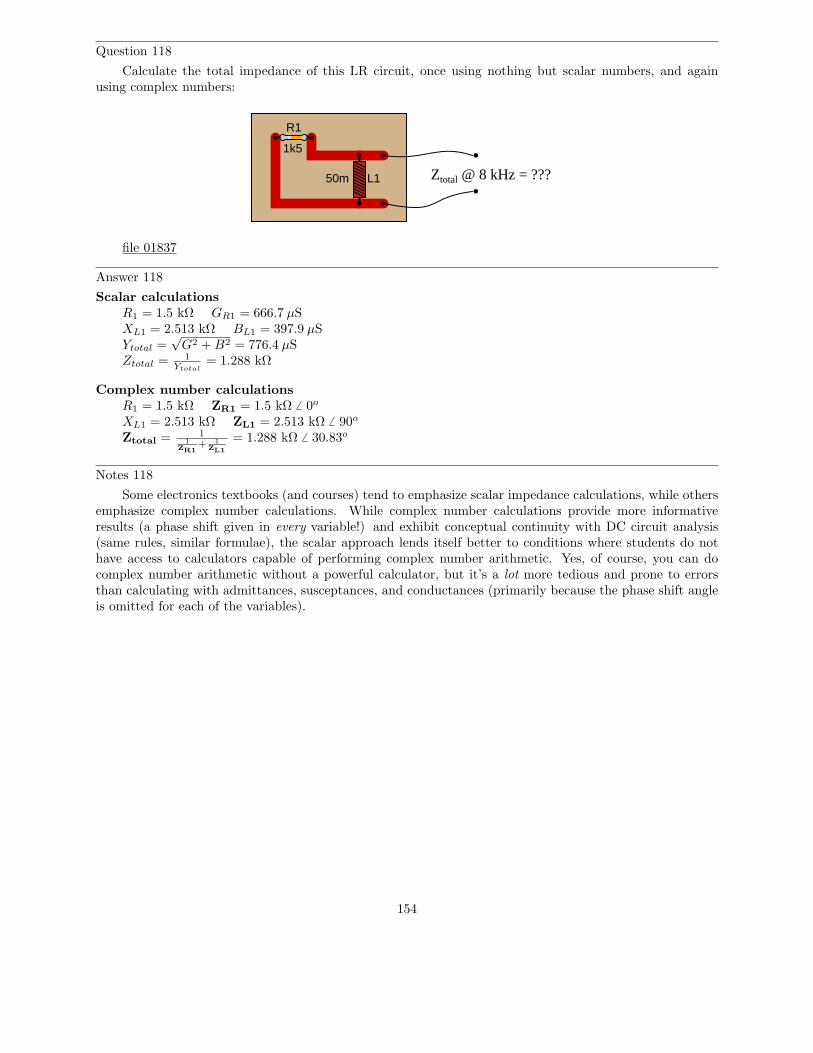
Question 118
Calculate the total impedance of this LR circuit, once using nothing but scalar numbers, and againusing complex numbers:
R1
L150m
1k5
Ztotal @ 8 kHz = ???
file 01837
Answer 118
Scalar calculationsR1 = 1.5 kΩ GR1 = 666.7 µSXL1 = 2.513 kΩ BL1 = 397.9 µSYtotal =
√G2 + B2 = 776.4 µS
Ztotal = 1
Ytotal= 1.288 kΩ
Complex number calculationsR1 = 1.5 kΩ ZR1 = 1.5 kΩ 6 0o
XL1 = 2.513 kΩ ZL1 = 2.513 kΩ 6 90o
Ztotal = 11
ZR1+ 1
ZL1
= 1.288 kΩ 6 30.83o
Notes 118
Some electronics textbooks (and courses) tend to emphasize scalar impedance calculations, while othersemphasize complex number calculations. While complex number calculations provide more informativeresults (a phase shift given in every variable!) and exhibit conceptual continuity with DC circuit analysis(same rules, similar formulae), the scalar approach lends itself better to conditions where students do nothave access to calculators capable of performing complex number arithmetic. Yes, of course, you can docomplex number arithmetic without a powerful calculator, but it’s a lot more tedious and prone to errorsthan calculating with admittances, susceptances, and conductances (primarily because the phase shift angleis omitted for each of the variables).
154
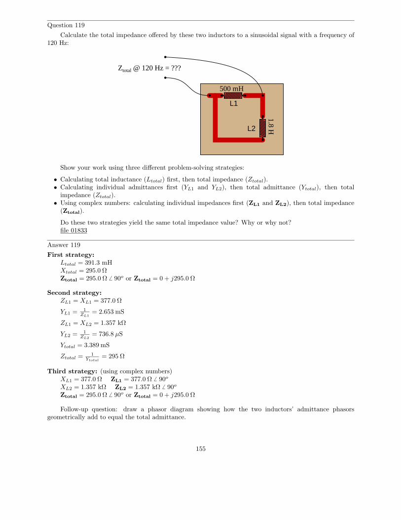
Question 119
Calculate the total impedance offered by these two inductors to a sinusoidal signal with a frequency of120 Hz:
L1
L2
Ztotal @ 120 Hz = ???
500 mH
1.8 H
Show your work using three different problem-solving strategies:
• Calculating total inductance (Ltotal) first, then total impedance (Ztotal).• Calculating individual admittances first (YL1 and YL2), then total admittance (Ytotal), then total
impedance (Ztotal).• Using complex numbers: calculating individual impedances first (ZL1 and ZL2), then total impedance
(Ztotal).
Do these two strategies yield the same total impedance value? Why or why not?file 01833
Answer 119
First strategy:Ltotal = 391.3 mHXtotal = 295.0 ΩZtotal = 295.0 Ω 6 90o or Ztotal = 0 + j295.0 Ω
Second strategy:ZL1 = XL1 = 377.0 Ω
YL1 = 1
ZL1
= 2.653 mS
ZL1 = XL2 = 1.357 kΩ
YL2 = 1
ZL2
= 736.8 µS
Ytotal = 3.389 mS
Ztotal = 1
Ytotal= 295 Ω
Third strategy: (using complex numbers)XL1 = 377.0 Ω ZL1 = 377.0 Ω 6 90o
XL2 = 1.357 kΩ ZL2 = 1.357 kΩ 6 90o
Ztotal = 295.0 Ω 6 90o or Ztotal = 0 + j295.0 Ω
Follow-up question: draw a phasor diagram showing how the two inductors’ admittance phasorsgeometrically add to equal the total admittance.
155

Notes 119
The purpose of this question is to get students to realize that any way they can calculate total impedanceis correct, whether calculating total inductance and then calculating impedance from that, or by calculatingthe impedance of each inductor and then combining impedances to find a total impedance. This should bereassuring, because it means students have a way to check their work when analyzing circuits such as this!
156
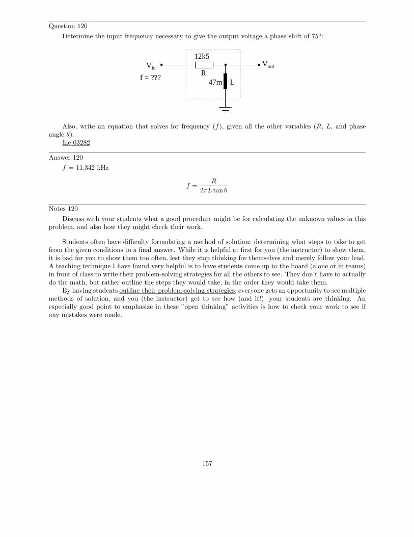
Question 120
Determine the input frequency necessary to give the output voltage a phase shift of 75o:
Vout
LR
47m
12k5Vin
f = ???
Also, write an equation that solves for frequency (f), given all the other variables (R, L, and phaseangle θ).
file 03282
Answer 120
f = 11.342 kHz
f =R
2πL tan θ
Notes 120
Discuss with your students what a good procedure might be for calculating the unknown values in thisproblem, and also how they might check their work.
Students often have difficulty formulating a method of solution: determining what steps to take to getfrom the given conditions to a final answer. While it is helpful at first for you (the instructor) to show them,it is bad for you to show them too often, lest they stop thinking for themselves and merely follow your lead.A teaching technique I have found very helpful is to have students come up to the board (alone or in teams)in front of class to write their problem-solving strategies for all the others to see. They don’t have to actuallydo the math, but rather outline the steps they would take, in the order they would take them.
By having students outline their problem-solving strategies, everyone gets an opportunity to see multiplemethods of solution, and you (the instructor) get to see how (and if!) your students are thinking. Anespecially good point to emphasize in these ”open thinking” activities is how to check your work to see ifany mistakes were made.
157
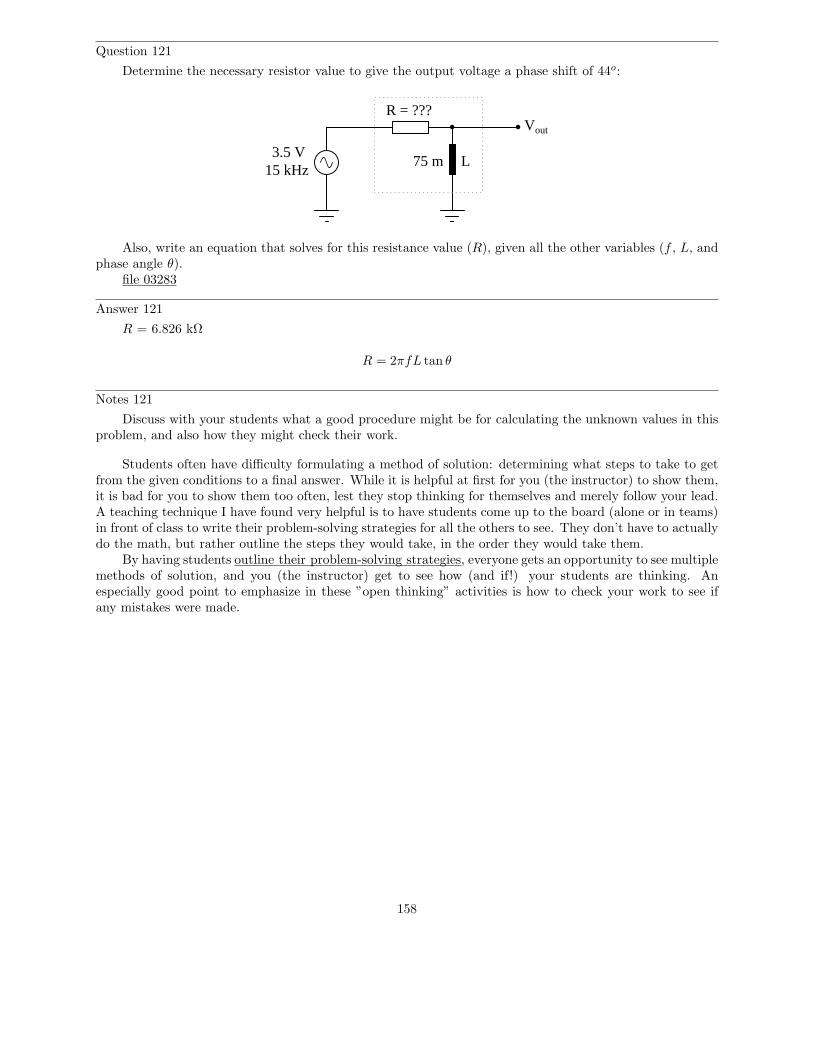
Question 121
Determine the necessary resistor value to give the output voltage a phase shift of 44o:
Vout
L75 m3.5 V
15 kHz
R = ???
Also, write an equation that solves for this resistance value (R), given all the other variables (f , L, andphase angle θ).
file 03283
Answer 121
R = 6.826 kΩ
R = 2πfL tan θ
Notes 121
Discuss with your students what a good procedure might be for calculating the unknown values in thisproblem, and also how they might check their work.
Students often have difficulty formulating a method of solution: determining what steps to take to getfrom the given conditions to a final answer. While it is helpful at first for you (the instructor) to show them,it is bad for you to show them too often, lest they stop thinking for themselves and merely follow your lead.A teaching technique I have found very helpful is to have students come up to the board (alone or in teams)in front of class to write their problem-solving strategies for all the others to see. They don’t have to actuallydo the math, but rather outline the steps they would take, in the order they would take them.
By having students outline their problem-solving strategies, everyone gets an opportunity to see multiplemethods of solution, and you (the instructor) get to see how (and if!) your students are thinking. Anespecially good point to emphasize in these ”open thinking” activities is how to check your work to see ifany mistakes were made.
158

Question 122
Determine the input frequency necessary to give the output voltage a phase shift of -40o:
VoutVin
f = ???
100m
2k1
L
R
Also, write an equation that solves for frequency (f), given all the other variables (R, L, and phaseangle θ).
file 03280
Answer 122
f = 2.804 kHz
f = −R tan θ
2πL
Notes 122
Discuss with your students what a good procedure might be for calculating the unknown values in thisproblem, and also how they might check their work.
Students often have difficulty formulating a method of solution: determining what steps to take to getfrom the given conditions to a final answer. While it is helpful at first for you (the instructor) to show them,it is bad for you to show them too often, lest they stop thinking for themselves and merely follow your lead.A teaching technique I have found very helpful is to have students come up to the board (alone or in teams)in front of class to write their problem-solving strategies for all the others to see. They don’t have to actuallydo the math, but rather outline the steps they would take, in the order they would take them.
By having students outline their problem-solving strategies, everyone gets an opportunity to see multiplemethods of solution, and you (the instructor) get to see how (and if!) your students are thinking. Anespecially good point to emphasize in these ”open thinking” activities is how to check your work to see ifany mistakes were made.
159
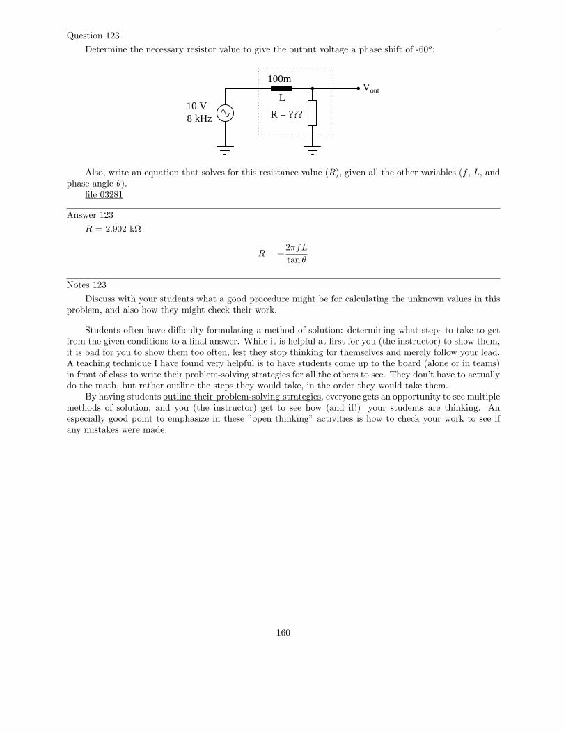
Question 123
Determine the necessary resistor value to give the output voltage a phase shift of -60o:
Vout
100m
L
R = ???10 V8 kHz
Also, write an equation that solves for this resistance value (R), given all the other variables (f , L, andphase angle θ).
file 03281
Answer 123
R = 2.902 kΩ
R = −2πfL
tan θ
Notes 123
Discuss with your students what a good procedure might be for calculating the unknown values in thisproblem, and also how they might check their work.
Students often have difficulty formulating a method of solution: determining what steps to take to getfrom the given conditions to a final answer. While it is helpful at first for you (the instructor) to show them,it is bad for you to show them too often, lest they stop thinking for themselves and merely follow your lead.A teaching technique I have found very helpful is to have students come up to the board (alone or in teams)in front of class to write their problem-solving strategies for all the others to see. They don’t have to actuallydo the math, but rather outline the steps they would take, in the order they would take them.
By having students outline their problem-solving strategies, everyone gets an opportunity to see multiplemethods of solution, and you (the instructor) get to see how (and if!) your students are thinking. Anespecially good point to emphasize in these ”open thinking” activities is how to check your work to see ifany mistakes were made.
160