Embed Size (px)
Citation preview

Elo TouchmonitorUser GuideFor 15” LCD Desktop1522L-XXWB Series
Revision A

Elo Touchmonitor User Guide
15" LCD Desktop
1522L-XXWB Series
Revision A
P/N E212991
Elo TouchSystems
1-800-ELOTOUCHwww.elotouch.com

Copyright © 2007 Tyco Electronics Corporation. All Rights Reserved.No part of this publication may be reproduced, transmitted, transcribed, stored in aretrieval system, or translated into any language or computer language, in any form or byany means, including, but not limited to, electronic, magnetic, optical, chemical, manual,or otherwise without prior written permission of Tyco Electronics.
DisclaimerThe information in this document is subject to change without notice. Tyco Electronicsmakes no representations or warranties with respect to the contents hereof, andspecifically disclaims any implied warranties of merchantability or fitness for aparticular purpose. Tyco Electronics reserves the right to revise this publication and tomake changes from time to time in the content hereof without obligation of TycoElectronics to notify any person of such revisions or changes.
Trademark AcknowledgmentsElo TouchSystems, IntelliTouch, SecureTouch, AccuTouch, and MonitorMouse aretrademarks of Tyco Electronics Corporation.Other product names mentioned herein may be trademarks or registered trademarks oftheir respective companies. Tyco Electronics claims no interest in trademarks other thanits own.
Chapter 1Introduction 1Product Description ................................................. 1Detailed LCD Display PerformanceRequirements .......................................................... 2
Credit Card Reader ........................................... 2External 12 VDC Power Supply ........................ 3
Chapter 2Installation and Setup 5Unpacking Your Touchmonitor. .............................. 5Product Overview .................................................... 6
Front View ......................................................... 6Rear View ......................................................... 7Side View .......................................................... 7Base Bottom View ............................................. 7Kensington™ Lock ............................................ 8
USB Interference Connection ................................. 9Remove the Back Cover ................................... 9Replace the Cable Cover .................................. 12
Optimizing the LCD Display .................................... 14Installing the Peripheral Device Drivers .................. 14
Magnetic Stripe Reader .................................. 14Testing the USB MSR Keyboard Emulation ... 14Testing the USB-HID Class MSR ................... 14Convert MSR from HID toKeyboard Emulation ....................................... 15
Installing the Touch Driver Software ....................... 19Installing the USB Touch Driver ........................ 19Installing APR USB Touch Driver for WindowsXP .................................................................... 19Installing the USB Touch Driver for WindowsXP, Windows 2000, Me, 98 ............................... 20
Chapter 3Operation 21About Touchmonitor Adjustments ........................... 21LCD Function Key ................................................... 22
Controls and Adjustment .............................. 23OSD Lock/Unlock ....................................... 23Power Lock/Unlock .................................... 23OSD Menu Functions ................................. 23OSD Control Options ................................. 24Brightness .................................................. 24Contrast ..................................................... 24Sharpness .................................................. 24Phase ......................................................... 24Auto Adjust ................................................. 24OSD Left/Right ........................................... 24OSD Up/Down ........................................... 24Clock .......................................................... 24Color Temperature ..................................... 24Current Input .............................................. 24OSD Position ............................................. 24Language ................................................... 24Recall Defaults ........................................... 24OSD Timeout ............................................. 24Input Video Select ...................................... 24Volume ....................................................... 24Power Save(No Input) ............................... 25
Power LED Display & Power Saving ............ 25General Power Saving Mode ..................... 25
Display Angle ...................................................... 25
Chapter 4Troubleshooting 27Solutions to Common Problems ......................... 27
Appendix ANative Resolution 29
Appendix BTouchmonitor Safety 31Care and Handling of Your Touchmonitor .......... 32
TTTTTaaaaabbbbble ofle ofle ofle ofle of Contents Contents Contents Contents Contents

Appendix CTechnical Specifications 33
Touchmonitor Specifications ......................... 34IntelliTouch TouchscreenSpecifications ................................................ 35Infrared Touchscreen Specifications ............ 36Acoustic Pulse Recognition Specifications ... 37AccuTouch Touchmonitor Specifications ...... 38Surface Capacity TouchscreenSpecifications ................................................ 3915” LCD Touchmonitor(1522L-XXXB-1-XX-G) Dimension ............... 40
Regulatory Information 41Warranty 46Index 47


C H A P T E R
1INTRODUCTION
Product Description
The 1522L is a retail terminal designed to present information to the operator and thecustomer. The 1522L is available in USB only. The 1522L functionally consists of a 15.0” LCD main display with a touchscreen, an optional magnetic stripe reader (MSR), anda two port USB Hub . The main display element is a 15” diagonal XGA resolution (1024x 768) LCD display. The main display consists of an LCD Display and touchscreen.1522L is available with Surface Capacitive, AccuTouch, IntelliTouch, CarrollTouchinfrared, and Acoustic Pulse Recognition (APR) touch technologies.
The MSR reads all three stripes on a standard credit card or drivers license. The creditcard is read by sliding the credit card, stripe side toward the display through the MSRforward or backward. There is a USB MSR only.The Hub provides two internal USB ports to be used by the MSR, and the touchscreenfor the USB version of the 1522L. The 1522L is powered by a universal AC powersource or 12 VDC from the external power source.
1-1

Magnetic Stripe ReaderThere is a USB MSR kit, which is sold separately. The USB version MSR is available inKeyboard emulation or HID. The MSR reads all three stripes on a standard credit cardor driver’s license.
Reference Standards-Conform to International Standards Organization, American National StandardsApplicable Standards Institute, California Drivers License, American Association of Motor
Vehicle AdministratorsMessage Format ACCIICard Speed 3 to 50 IPSMTBF Electronics 125,000 hrs; Head 1,000,000 passes
Detailed LCD Display Performance Requirements
15” TFT LCD Display PanelDisplay Format 1024 x 768Display Area 15” 304.1mm(H) x 228mm(V)Pixel Pitch 15” 0.297mm(H) x 0.297mm(V)Contrast Ratio Typical 500:1; min. 400:1Brightness
AccuTouch Typical 200 cd/m2 ; min 160 cd/m2 (min)IntelliTouch Typical 230 cd/m2 ; min 184 cd/m2 (min)Surface Capacitive Typical 210 cd/m2 ; min 168 cd/m2 (min)CarrollTouch Infrared Typical 230 cd/m2 ; min 184 cd/m2 (min)APR Typical 230 cd/m2 ; min 184 cd/m2 (min)
Response Time 8.5 ms/6 ms typical, 11 ms/10 ms maxDisplay Color 16.2 M colors, with frame rate controlVertical Viewing Angle CR>=10 60o(up)/60o(down) typical
55o(up)/45o(down) typicalHorizontal Viewing Angle CR>=10 70o(up)/70o(down) typical
60o(up)/60o(down) typical
1-2 Elo Touchmonitor User Guide
1-3
External Power Supply
The 1522L shall be powered by a universal AC power source or 12 VDC from externalpower source. The power supply shall provide the following capability:AC power: Input voltage 85 to 265 VacInput frequency 47 to 63HzDC power: Input voltage 12 VdcInput line and load regulation +/-2%

1-4 Elo Touchmonitor User Guide
C H A P T E R
2INSTALLATION AND SETUP
This chapter discusses how to install your LCD touchmonitor and how to install EloTouchSystems driver software.
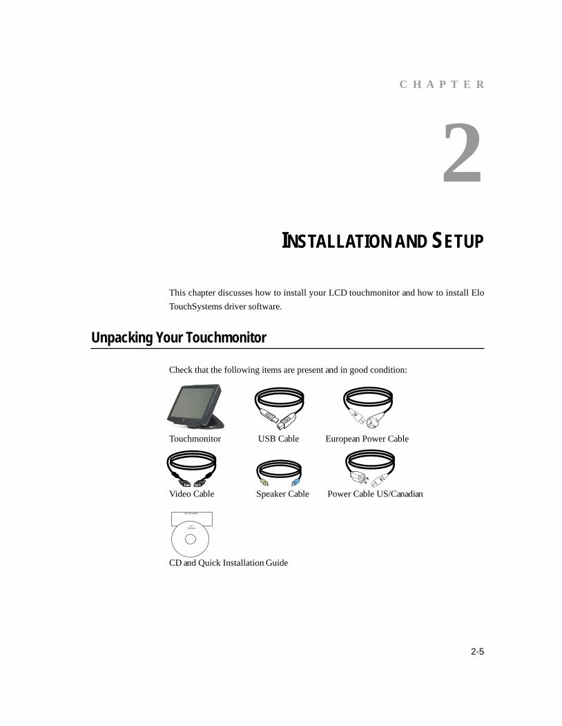
Unpacking Your Touchmonitor
Check that the following items are present and in good condition:
Touchmonitor USB Cable European Power Cable
Video Cable Speaker Cable Power Cable US/Canadian
CD and Quick Installation Guide
2-5
Elo QuickStart
CDSoftware

2-6 Elo Touchmonitor User Guide
Product Overview
Front View
Rear View

Side View
Base Bottom View
2-7

KensingtonTM Lock
The KensingtonTM lock is a security device that help to preventtheft. To find out more about this security device, go to http://www.kensington.com.
2-8 Elo Touchmonitor User Guide

USB Interface Connection
Your touchmonitor comes with only one touchscreen USB connector cable. (For Win-dows 2000, Me, and XP systems only.)To set up the display, please refer to the following figures and procedures:
Remove the Cable Cover
The cables are connected at the back of the monitor.
cable cover
To remove the cover, grasp the lip of the cover and pull towards you until it snaps off.
2-9
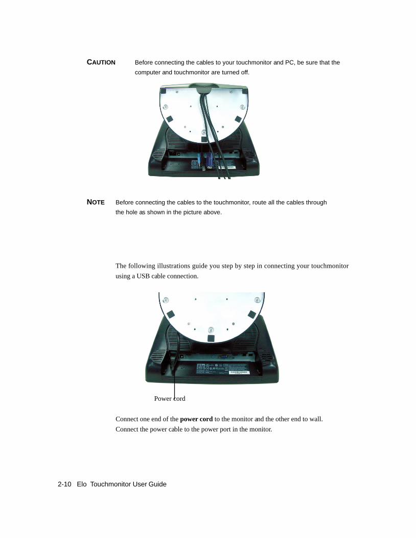
The following illustrations guide you step by step in connecting your touchmonitorusing a USB cable connection.
Power cord
Connect one end of the power cord to the monitor and the other end to wall.Connect the power cable to the power port in the monitor.
CAUTION Before connecting the cables to your touchmonitor and PC, be sure that thecomputer and touchmonitor are turned off.
NOTE Before connecting the cables to the touchmonitor, route all the cables throughthe hole as shown in the picture above.
2-10 Elo Touchmonitor User Guide

2-11
Speaker cable
Connect one end of the speaker cable to the speaker port in the computer and the otherend to the port in the monitor.
Video cable
Connect one end of the video cable to the rear side of computer and the other to theLCD monitor. Tighten by turning the two thumb screws clockwise to ensure propergrounding.
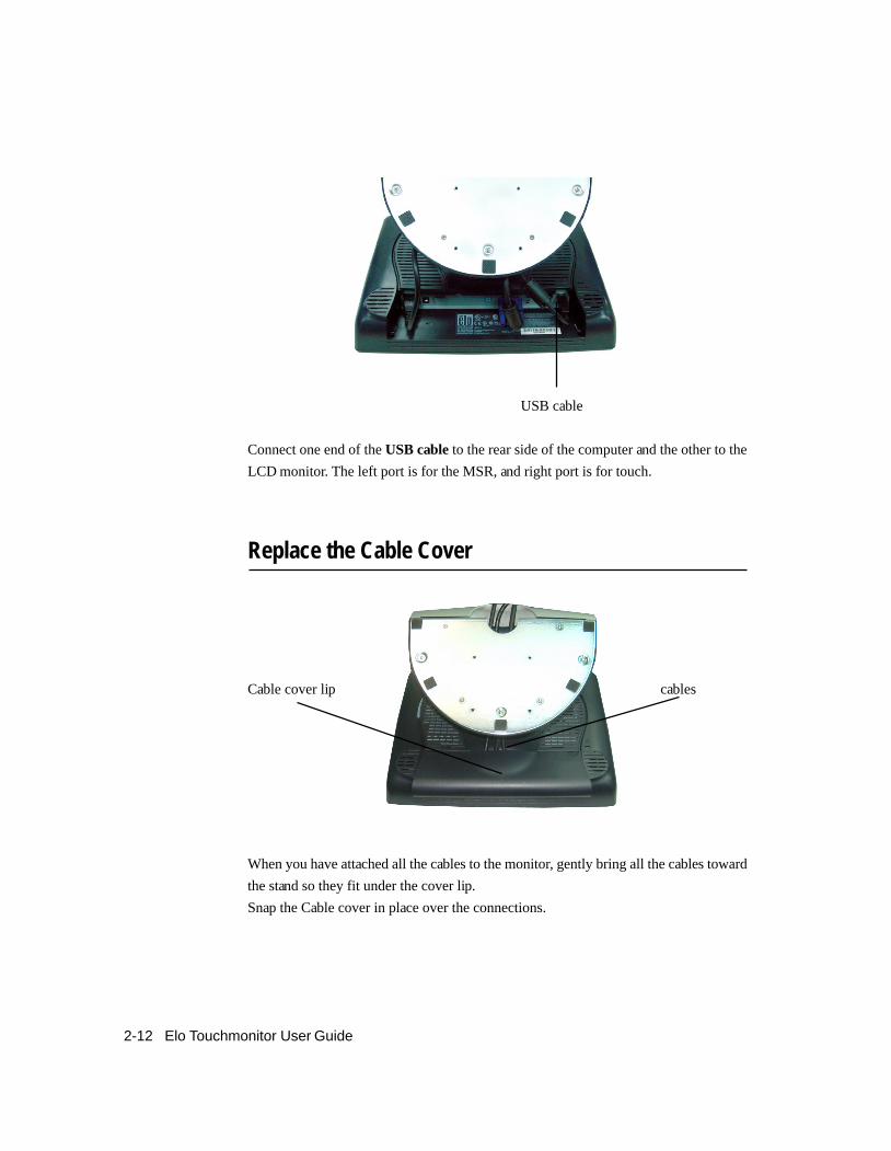
Replace the Cable Cover
Cable cover lip cables
When you have attached all the cables to the monitor, gently bring all the cables towardthe stand so they fit under the cover lip.Snap the Cable cover in place over the connections.
USB cable
Connect one end of the USB cable to the rear side of the computer and the other to theLCD monitor. The left port is for the MSR, and right port is for touch.
2-12 Elo Touchmonitor User Guide

2-13
Optimizing the LCD Display
To ensure the LCD display works well with your computer, configure the display modeof your graphic card to make it less than or equal to 1024 x 768 resolution, and makesure the timing of the display mode is compatible with the LCD display. Refer toAppendix A for more information about resolution. Compatible video modes for yourtouchmonitor are listed in Appendix C.
Installing the Peripheral Device Drivers
Magnetic Stripe Reader
No devices are needed.
Testing the USB MSR Keyboard Emulation1 Plug in the device.2 Open MS Word.3 Slide the card through the MSR to view the data.
Testing the USB-HID Class MSR1 On the CD, browse to Touch Monitor Peripherals\Magnetic Stripe Card
Readers\Demo.2 Open the Readme.txt and follow instructions to test the unit.

Convert MSR from HID to keyboard emulationMSR Conversion:Get program @ http://www.magtek.com/support/software/demo_programs/usb_swipe_insert_reader.aspFrom the CD, select Touch Monitor Peripherals. Select the ET1529 HID-KB Conver-sion folder, and follow the instructions in the folder.
1. To convert from HID to Keyboard Emulation Mode.1.1 Double click on HID MSR icon on the desktop.
The following window will appear
1.2 Click on About to verify version
1.3 Close About dialog box.1.4 Click on Read Cards.1.5 This dialog will appear
2-14 Elo Touchmonitor User Guide
2-15
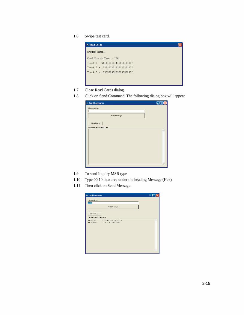
1.6 Swipe test card.
1.7 Close Read Cards dialog.1.8 Click on Send Command. The following dialog box will appear
1.9 To send Inquiry MSR type1.10 Type 00 10 into area under the heading Message (Hex)1.11 Then click on Send Message.

1.12 The DATA=00 means it’s USB HID.1.13 Switch to Keyboard Emulation1.14 Type 01 10 01 into area under the heading Message (Hex)1.15 Then click on Send Message.
1.16 Send inquiry MSR type1.17 Type 00 10 into area under the heading Message (Hex)1.18 Then click on Send Message.
1.19 The DATA=01 means its USB Keyboard Emulation.1.20 You must now reset the MSR by sending the command 02.1.21 Type 02 into area under the heading Message (Hex)
2-16 Elo Touchmonitor User Guide

2-17
1.22 Then click on Send Message.
1.23 Double click on The KB MSR Test icon in the desktop and slide the test c card.The following icon will appear
1.24 Done.

Installing the Touch Driver Software
Elo TouchSystems provides driver software that allows your touchmonitor to work withyour computer. Drivers are located on the enclosed CD-ROM for the following operat-ing systems:
• Windows XP• Windows 2000• Windows Me• Windows 98• Windows 95• Windows NT 4.0• CE 2.x, 3.0, 4x• Windows XP Embedded• Windows 3.x• MS DOS• OS/2
Additional drivers and driver information for other operating systems (includingMacintosh and Linux) are available on the Elo TouchSystems web site at www.elotouch.com.
Your Elo USB touchmonitor is Plug-and-Play compliant. Information on the videocapabilities of your touchmonitor is sent to your video display adapter when Windowsstarts. If Windows detects your touchmonitor, follow the instructions on the screen toinstall a generic Plug-and-Play monitor.Refer to the appropriate section for driver installation instructions.
Installing APR USB Touch Driver for Windows XP
Insert the ELO APR CD-ROM in your computer’s CD-ROM driver.Follow the directions on the screen to complete the APR 2.0 driver setup for yourversion of Windows.1 Click Start > Run.2 Click the Browse button to locate the SW600117.exe program on the CD-ROM.3 Click Open, then OK to run SW600117.exe.4 Follow the directions on the screen to complete the driver setup for your version
of Windows.
2-18 Elo Touchmonitor User Guide
2-19
Installing the USB Touch Driver
Installing the USB Touch Driver for Windows XP, Windows 2000,Me and 981 Insert the Elo CD-ROM in your computer’s CD-ROM drive.
If Windows XP, Windows 2000,Windows 98, or Windows Me starts the Add NewHardware Wizard:
2 Choose Next. Select “Search for the best driver for your device (recommended)” andchoose Next.
3 When a list of search locations is displayed, place a checkmark on “Specify alocation” and use Browse to select the \EloUSB directory on the Elo CD-ROM.
4 Choose Next. Once the Elo TouchSystems USB touchscreen driver has been detected,choose Next again.
5 You will see several files being copied. Insert your Windows 98 CD if prompted.Choose Finish.
If Windows XP, Windows 2000,Windows 98, or Windows Me does not start the AddNew Hardware Wizard:
NOTE: For Windows XP and Windows 2000 you must have administrator accessrights to install the driver.1 Insert the Elo CD-ROM in your computer’s CD-ROM drive. If the AutoStart feature
for your CD-ROM drive is active, the system automatically detects the CD and startsthe setup program.
2 Follow the directions on the screen to complete the driver setup for yourversion of Windows. If the AutoStart feature is not active:1 Click Start > Run.2 Click the Browse button to locate the EloCd.exe program on the CD-ROM.3 Click Open, then OK to run EloCd.exe.4 Follow the directions on the screen to complete the driver setup for your
version of Windows.

2-20 Elo Touchmonitor User Guide

C H A P T E R
3OPERATION
About Touchmonitor Adjustments
Your touchmonitor will unlikely require adjustment. Variations in video output andapplication may require adjustments to your touchmonitor to optimize the quality of thedisplay. For best performance, your touchmonitor should be operating in its nativeresolution, which is 1024 x 768 at 60-75 Hz. Use the Display control panel in Windowsto choose 1024 x 768 resolution. Operating in other resolutions will degrade videoperformance. For further information, please refer to Appendix A.
All adjustments you make to the controls are automatically memorized. This featuresaves you from having to reset your choices every time you unplug or power yourtouchmonitor off and on. If there is a power failure your touchmonitor settings will notdefault to the factory specifications. To restore factory set up, choose it from the OSD.See page 3-26.
3-21

5
4
3
2
1
LCD Function Key
Controls Function1 Power Switch Turns the display system power on or off.2 Select Displays the OSD menus on the screen and used to input the OSD control options
on the screen.3 Adjusts the decreasing value of the selected OSD control option.4 Adjusts the increasing value of the selected OSD control option.5 Menu Menu display and menu exit.
3-22 Elo Touchmonitor User Guide

Controls and AdjustmentOSD Lock/UnlockYou are able to lock and unlock the OSD feature. The monitor is shipped in the unlockedposition.To lock the OSD:1 Press the Menu button and button simultaneously for 2 seconds. A window will
appear displaying “OSD Unlock”. Continue to hold the buttons down for another 2seconds and the window toggles to “OSD Lock”.
Power Lock/UnlockYou are able to lock/unlock the power feature. The monitor is shipped in theunlocked position.To lock the power:
1 Press the Menu button and the simultaneously for 2 seconds. A window for another2 seconds and the window toggles to —”Power Lock“.
OSD Menu FunctionsTo display the OSD Menu press the Menu button.1 Press the button or button to select the different OSD control option.2 When the function you want to change is displayed, press the Select button.
To adjust the Value of the function:1 Pressing the button increases the value of the selected OSD control option.2 Pressing the button decreases the value of the selected OSD control option.After adjusting the values, the monitor will automatically save the changes.
NOTE: The OSD screen will disappear if no input activities are detected for 45 seconds.
3-23
OSD Control Options
Brightness• Background luminance of the LCD panel is adjusted.
Contrast• Adjusts the contrast or the values of color gain (red, green or blue).
Sharpness• The sharpness can be adjustable.
Phase• Adjusts the phase of the dot clock.
Auto Adjust• Clock system auto adjustment (under 5 seconds).
OSD Left/Right• The OSD screen is moved horizontally right and left.
OSD Up/Down• The OSD screen is moved vertically up and down.
Clock• Adjusts the ratio of dividing frequency of the dot clock.
Color Temperature• Sets R, G, B gain.
Current Input• The frequency of the horizontal/vertical synchronizing signal under the inputindicated. (This information is under the Auto Adjust icon)
OSD Position• Allows the OSD indicator position to be selected.
Language• Select the language used for the OSD menu from among English, French, German,Spanish and Japanese.
Recall Defaults• All data copy from factory shipment data.
OSD Timeout• Adjusts time for OSD menu to disappear.
Input Video Select• Select D-SUB analog, DVI digital signal.
Volume• To increase or decrease the sound level.
3-24 Elo Touchmonitor User Guide

Power-Save (No Input)• The LCD panel background is cut when there is no signal input (AC line power consumption of 4w or less).
Power LED Display & Power Saving
General Power Saving ModeWhen the power switch is on, this LED light is green.The LED indicates the different power status with altered LED colors when the monitoroperates in different modes (see following table).
PowerMode Consumption IndicatorOn 30w max. GreenSleep 4w max. OrangeOff 2w NO
We recommend switching the monitor off when it is not in use for a long period of time.
Display Angle
For viewing clarity, you can tilt the LCD forward up 67 to 90 degrees.
3-25
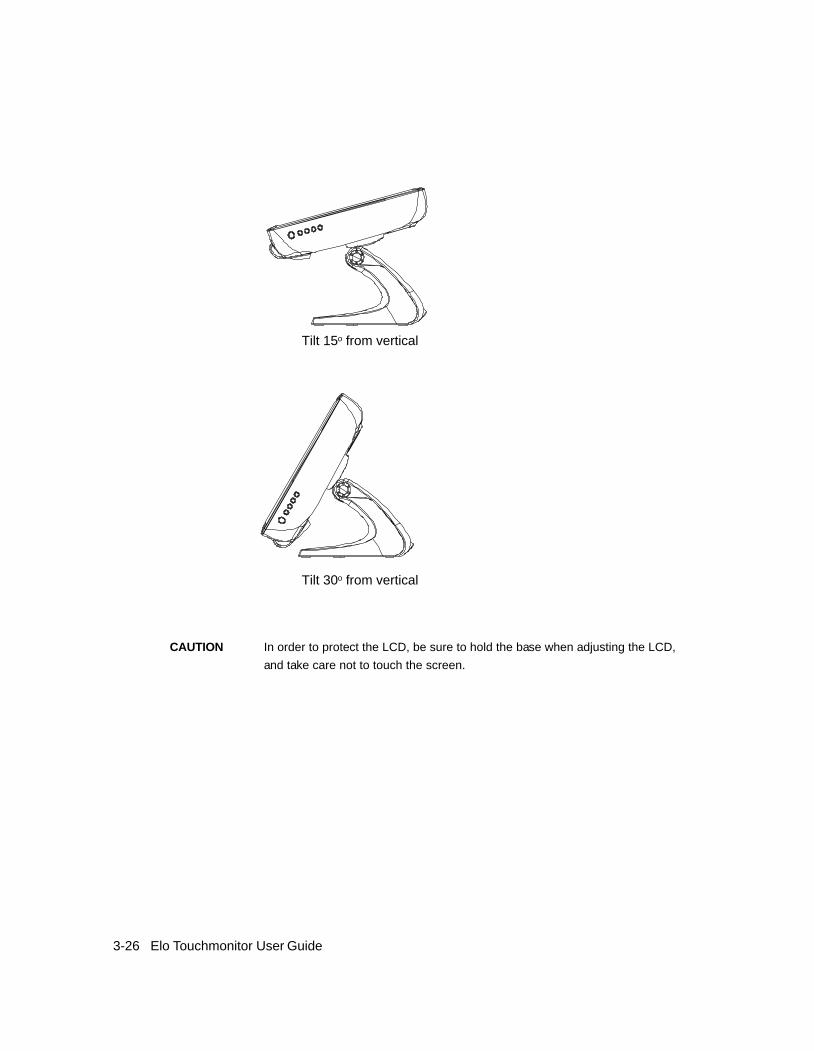
CAUTION In order to protect the LCD, be sure to hold the base when adjusting the LCD,and take care not to touch the screen.
3-26 Elo Touchmonitor User Guide
Tilt 15o from vertical
Tilt 30o from vertical

C H A P T E R
4TROUBLESHOOTING
If you are experiencing trouble with your touchmonitor, refer to the following table. Ifthe problem persists, please contact your local dealer or our service center. Elo Techni-cal Support numbers are listed on the last page of this manual.
Solutions to Common Problems
Problem Suggestion(s)The monitor does not respond after Check that the monitor’s Power Switch is on.you turn on the system. Turn off the power and check the monitor’s power cord and signal
cable for proper connection.Characters on the screen are dim Refer to the Controls and Adjustments section to adjust the brightness.The screen is blank During operation, the monitor screen may automatically turn off as a
result of the Power Saving feature. Press any key to see if the screenreappears.Refer to the Controls and Adjustments section to adjust thebrightness.
OSD or power buttons don’t work Check to see that they are not locked out. See page 3-25.“Out of Range” display check to see of the resolution or vertical frequency of your computer is
higher than that of the LCD display.Reconfigure the resolution of yourcomputer to make it less than or equal to 1024 x 768. 1024 x 768 isoptimal. See Appendix A for more information on resolution.
Touch doesn’t work Make sure cable is securely attached at both ends.
4-27

4-28 Elo Touchmonitor User Guide

C H A P T E R
ANATIVE RESOLUTION
The native resolution of a monitor is the resolution level at which the LCD panel isdesigned to perform best. For the Elo LCD touchmonitor, the native resolution is 1024x 768 for the 15” size. In almost all cases, screen images look best when viewed at theirnative resolution. You can lower the resolution setting of a monitor but not increase it.
Input Video 15.0" LCD640 x 480 (VGA) Transforms input format to 1024 x 768800 x 600 (SVGA) Transforms input format to 1024 x 7681024 x 768 (XGA) Display in native resolution
The native resolution of an LCD is the actual number of pixels horizontally in the LCDby the number of pixels vertically in the LCD. LCD resolution is usually represented bythe following symbols:
VGA 640 x 480SVGA 800 x 600XGA 1024 x 768
A-29

As an example, a SVGA resolution LCD panel has 800 pixels horizontally by 600 pixelsvertically. Input video is also represented by the same terms. XGA input video has aformat of 1024 pixels horizontally by 768 pixels vertically. When the input pixels con-tained in the video input format match the native resolution of the panel, there is a one toone correspondence of mapping of input video pixels to LCD pixels. As an example, thepixel in column 45 and row 26 of the input video is in column 45 and row 26 of the LCD.For the case when the input video is at a lower or higher resolution than the nativeresolution of the LCD, the direct correspondence between the video pixels and the LCDpixels is lost. The LCD controller can compute the correspondence between video pix-els and LCD pixels using algorithms contained on its controller. The accuracy of thealgorithms determines the fidelity of conversion of video pixels to LCD pixels. Poorfidelity conversion can result in artifacts in the LCD displayed image such as varyingwidth characters.
A-30 Elo Touchmonitor User Guide

C H A P T E R
BTOUCHMONITOR SAFETY
This manual contains information that is important for the proper setup and maintenanceof your touchmonitor. Before setting up and powering on your new touchmonitor, readthrough this manual, especially Chapter 2 (Installation and Setup), and Chapter 3(Operation).1 To reduce the risk of electric shock, follow all safety notices and never open the
touchmonitor case.2 Turn off the product before cleaning.3 Your new touchmonitor is equipped with a three-wire, grounding power cord. The
power cord plug will only fit into a grounded outlet. Do not attempt to fit the plug intoan outlet that has not been configured for this purpose. Do not use a damaged powercord. Use only the power cord that comes with your Elo TouchSystems touchmonitor.Use of an unauthorized power cord may invalidate your warranty.
4 The slots located on the sides and top of the touchmonitor case are for ventilation. Donot block or insert anything inside the ventilation slots.
5 It is important that your touchmonitor remains dry. Do not pour liquid into or ontoyour touchmonitor. If your touchmonitor becomes wet do not attempt to repair ityourself.
B-31

Care and Handling of Your Touchmonitor
The following tips will help keep your Elo touchmonitor functioning at the optimallevel.
• To avoid risk of electric shock, do not disassemble the brick supply or display unitcabinet. The unit is not user serviceable. Remember to unplug the display unit fromthe power outlet before cleaning.
• Do not use alcohol (methyl, ethyl or isopropyl) or any strong dissolvent. Do not usethinner or benzene, abrasive cleaners or compressed air.
• To clean the display unit cabinet, use a cloth lightly dampened with a mild detergent.• Avoid getting liquids inside your touchmonitor. If liquid does get inside, have a
qualified service technician check it before you power it on again.• Do not wipe the screen with a cloth or sponge that could scratch the surface.• To clean the touchscreen, use window or glass cleaner. Put the cleaner on the rag and
wipe the touchscreen. Never apply the cleaner directly on the touchscreen .
B-32 Elo Touchmonitor User Guide

C H A P T E R
CTECHNICAL SPECIFICATIONS
Display ModesYour Elo touchmonitor is compatible with the following standard video modes:
Item Resolution Type H. Scan(KHz) V. Scan(Hz) Pol.1 640 x 350 VGA 31.469 70.087 + / 2 720 x 400 VGA 31.469 70.087 - / +3 640 x 480 VGA 31.469 59.940 - / 4 640 x 480 VESA72 37.861 72.809 -/5 640 x 480 VESA75 37.500 75.000 -/6 800 x 600 SVGA 35.156 56.250 +/+7 800 x 600 SVGA 37.879 60.317 +/+8 800 x 600 VESA72 48.077 72.188 +/+9 800 x 600 VESA75 46.875 75.000 +/+10 1024 x 768 XGA 48.363 60.004 -/-11 1024 x 768 XGA 56.476 70.069 -/-12 1024 x 768 VESA75 60.023 75.029 +/+
C-33

Touchmonitor Specifications
Model 1522LLCD Display 15.0” TFT Active Matrix PanelDisplay Size 304.1(H) x 228(V) mmPixel Pitch 0.297(H) x 0.297(V) mmDisplay Mode VGA 640 x 350 (70 Hz)
VGA 720 x 400 (70 Hz)VGA 640 x 480 (60 / 72 / 75 Hz)SVGA 800 x 600 (56 / 60 / 72 / 75Hz)XGA 1024 x 768 (60 / 70 / 75Hz)
Native XGA 1024 x 768Contrast Ratio 500 : 1 (typical); min. 400:1Brightness
AccuTouch Typical 200 cd/m2; min. 160 cd/m2
IntelliTouch Typical 230 cd/m2; min. 184 cd/m2
CarrollTouch Infrared Typical 230 cd/m2; min. 184 cd/m2
Surface Capacitive Typical 210 cd/m2; min. 168 cd/m2
Acoustic Pulse Recognition (APR) Typical 230 cd/m2; min. 184 cd/m2
Response Time Rise/Fall 8.5/6 ms typical, 11 ms/10 ms max.Display Color 16.2M colors, with frame rate controlViewing Angle CR>=10 (L/R)= -70o/+70o (typical), (U/D) -60o/+60o (typical)Input Signal VGA Analog Video R.G.B. Analog 0.7V peak to peak
Sync TTL Positive or Negative, Composite Sync, Sync on greenSignal Connector 15 Pin D-SubFront Control Power on / off , Menu, , , SelectOSD Contrast, Brightness, H/V-Position, Recall default,
Color Temperature, Volume, Sharpness,Phase, Clock OSD H/V position, OSD Time, Auto Adjust,OSD Language, Input Select
Plug & Play DDC 2BTouch Panel (optional) AccuTouch, IntelliTouch, Surface Capacitive, CarrollTouch, APRPower Input: AC 85-265V, 47-63Hz, or DC 12V/4A (max.)Operating Conditions Temp 0oC ~ 40oC (41oF ~ 95oF)
Humidity 20% ~ 80% (No Condensation)Altitude To 12,000 Feet
Dimensions (HxWxD) 354 x 286 x 265mmWeight (Net) 20.1lbs., monitor weight 16.2 lbs.Certifications EMC CE, C-Tick, FCC, VCCI(Class B)
Safety CB, CE, cULus, S(Argentina), Semko S Mark
C-34 Elo Touchmonitor User Guide

IntelliTouch Touchscreen Specifications
MechanicalPositional Accuracy Standard deviation of error is less than 0.080 in. (2.03 mm).
Equates to less than ±1%.Touchpoint Density More than 100,000 touchpoints/in2 (15,500 touchpoints/cm2).Touch Activation Force Typically less than 3 ounces (85 grams).Surface Durability Surface durability is that of glass, Mohs’ hardness rating of 7.Expected Life Performance No known wear-out mechanism, as there are no layers, coatings,
or moving parts. IntelliTouch technology has been operationallytested to more than 50 million touches in one location withoutfailure, using a stylus similar to a finger.
Sealing Unit is sealed to protect against splashed liquids, dirt, and dust.OpticalLight Transmission (per ASTM 92%D1003)Visual Resolution All measurements made using USAF 1951 Resolution Chart,
under 30X magnification, with test unit located approximately1.5 in (38 mm) from surface of resolution chart.Clear surface: Excellent, with no noticeable degradation.Antiglare surface: 6:1 minimum.
Gloss (per ASTM D2457using a 60-degree gloss meter) Antiglare surface: Curved: 60 ± 20 gloss units or 75 ± 15 gloss
units.EnvironmentalChemical Resistance The active area of the touchscreen is resistant to all chemicals
that do not affect glass, such as:AcetoneTolueneMethyl ethyl ketoneIsopropyl alcoholMethyl alcoholEthyl acetateAmmonia-based glass cleanersGasolineKeroseneVinegar
Electrostatic Protection (per Meets Levels 4 (15kV air/8 kV contact discharge)EN 61 000-4-2, 1995)
C-35

CarrollTouch Infrared Touchscreen Specifications
MechanicalInput Method Finger or gloved hand activationElectricalPositional Accuracy Typical centroid accuracy: 2 mm with 1 mm STD errorResolution Touchpoint density is based on controller resolution of 4096 x 4096Touch Activation Force No minimum touch activation force is requiredController Board: Serial (RS232) or USB 1.1OpticalLight Transmission Glass overlay: 92% per ASTM D1003-92 EnvironmentalChemical Resistance Glass overlays: The touch active area of the touchscreen is
resistant to chemicals that do not affect glass, such as: acetone,toluene, methyl ethyl ketone, isopropyl alcohol, methyl alcohol,ethyl acetate, ammonia-based glass cleaners, gasoline, kerosene,vinegar. Polycarbonate bezel: around perimeter of display hassome sensitivity to hydrocarbons.
DurabilitySurface Durability Glass filter option: Surface durability is that of glass, Mohs’
hardness rating of 7.
C-36 Elo Touchmonitor User Guide

Acoustic Pulse Recognition Specifications
MechanicalInput Method Finger, finger nail, gloved hand, or stylus activationElectricalPosition Accuracy 1% max. errorResolution Accuracy Touchpoint density is based on controller resolution of 4096 x 4096Touch Activation Force Typically 2 to 3 ounces (55 to 85 grams)Controller Board: USB 1.1OpticalLight Transmission 90%+/-5%EnvironmentalChemical resistance The touch activation area of the touchscreen is resistant to chemicals
that do not affect glass such as: acetone, toluene, methyl ethyl ketone,isopropyl alcohol, methyl alcohol, ethyl acetate, ammonia-based glasscleaners, gasoline, kerosene, vinegar
DurabilitySurface Durability Surface durability is that of glass, Mohs’ hardness rating of 7Expected Life No known wear-out mechanism, as there are no layers, coatings, or moving
parts. APR technology has been operationally tested to more than 50million touches in one location without failure, using a stylus similarfinger.
C-37
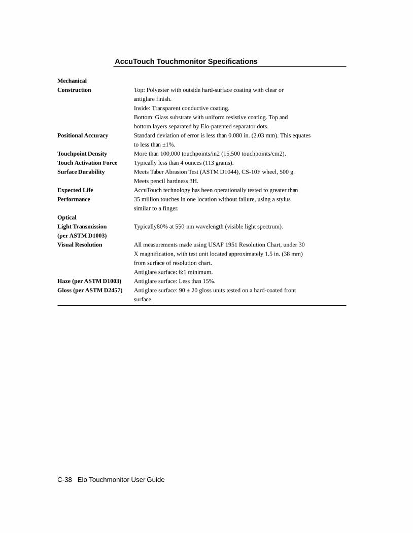
AccuTouch Touchmonitor Specifications
MechanicalConstruction Top: Polyester with outside hard-surface coating with clear or
antiglare finish.Inside: Transparent conductive coating.Bottom: Glass substrate with uniform resistive coating. Top andbottom layers separated by Elo-patented separator dots.
Positional Accuracy Standard deviation of error is less than 0.080 in. (2.03 mm). This equatesto less than ±1%.
Touchpoint Density More than 100,000 touchpoints/in2 (15,500 touchpoints/cm2).Touch Activation Force Typically less than 4 ounces (113 grams).Surface Durability Meets Taber Abrasion Test (ASTM D1044), CS-10F wheel, 500 g.
Meets pencil hardness 3H.Expected Life AccuTouch technology has been operationally tested to greater thanPerformance 35 million touches in one location without failure, using a stylus
similar to a finger.OpticalLight Transmission Typically80% at 550-nm wavelength (visible light spectrum).(per ASTM D1003)Visual Resolution All measurements made using USAF 1951 Resolution Chart, under 30
X magnification, with test unit located approximately 1.5 in. (38 mm)from surface of resolution chart.Antiglare surface: 6:1 minimum.
Haze (per ASTM D1003) Antiglare surface: Less than 15%.Gloss (per ASTM D2457) Antiglare surface: 90 ± 20 gloss units tested on a hard-coated front
surface.
C-38 Elo Touchmonitor User Guide
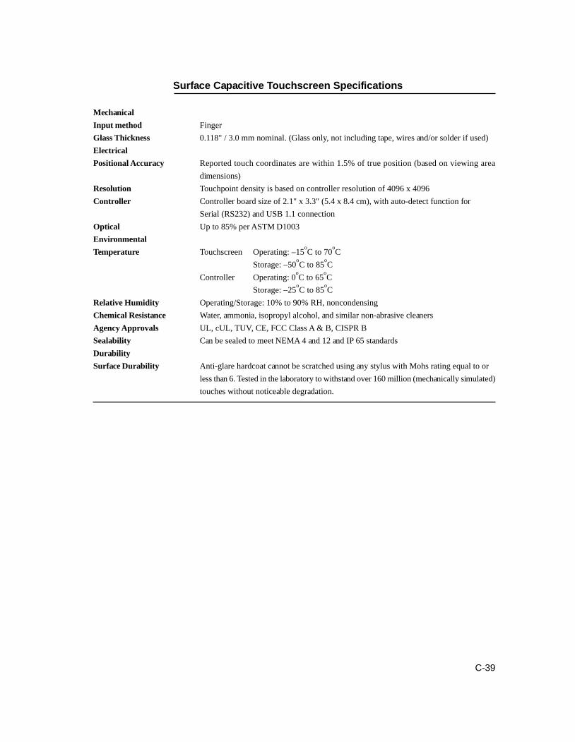
Surface Capacitive Touchscreen Specifications
MechanicalInput method FingerGlass Thickness 0.118" / 3.0 mm nominal. (Glass only, not including tape, wires and/or solder if used)ElectricalPositional Accuracy Reported touch coordinates are within 1.5% of true position (based on viewing area
dimensions)Resolution Touchpoint density is based on controller resolution of 4096 x 4096Controller Controller board size of 2.1" x 3.3" (5.4 x 8.4 cm), with auto-detect function for
Serial (RS232) and USB 1.1 connectionOptical Up to 85% per ASTM D1003EnvironmentalTemperature Touchscreen Operating: –15oC to 70oC
Storage: –50oC to 85oCController Operating: 0oC to 65oC
Storage: –25oC to 85oCRelative Humidity Operating/Storage: 10% to 90% RH, noncondensingChemical Resistance Water, ammonia, isopropyl alcohol, and similar non-abrasive cleanersAgency Approvals UL, cUL, TUV, CE, FCC Class A & B, CISPR BSealability Can be sealed to meet NEMA 4 and 12 and IP 65 standardsDurabilitySurface Durability Anti-glare hardcoat cannot be scratched using any stylus with Mohs rating equal to or
less than 6. Tested in the laboratory to withstand over 160 million (mechanically simulated)touches without noticeable degradation.
C-39

C-40 Elo Touchmonitor User Guide
15” LCD Touchmonitor(1522L-XXXB-1-XX-G) Dimensions

REGULATORY INFORMATION
I. Electrical Safety Information:A) Compliance is required with respect to the voltage, frequency, and current require-ments indicated on the manufacturer’s label. Connection to a different power sourcethan those specified herein will likely result in improper operation, damage to the equip-ment or pose a fire hazard if the limitations are not followed.B) There are no operator serviceable parts inside this equipment. There are hazardousvoltages generated by this equipment which constitute a safety hazard. Service shouldbe provided only by a qualified service technician.C) This equipment is provided with a detachable power cord which has an integral safetyground wire intended for connection to a grounded safety outlet.
1) Do not substitute the cord with other than the provided approved type. Underno circumstances use an adapter plug to connect to a 2-wire outlet as this willdefeat the continuity of the grounding wire.2) The equipment requires the use of the ground wire as a part of the safetycertification, modification or misuse can provide a shock hazard that can resultin serious injury or death.3) Contact a qualified electrician or the manufacturer if there are questions aboutthe installation prior to connecting the equipment to mains power.
II. Emissions and Immunity InformationA) Notice to Users in the United States: This equipment has been tested and found tocomply with the limits for a Class B digital device, pursuant to Part 15 of FCC Rules.These limits are designed to provide reasonable protection against harmful interferencein a residential installation. This equipment generates, uses, and can radiate radio fre-quency energy, and if not installed and used in accordance with the instructions, maycause harmful interference to radio communications.B) Notice to Users in Canada: This equipment complies with the Class B limits for radionoise emissions from digital apparatus as established by the Radio Interference Regula-tions of Industrie Canada.C) Notice to Users in the European Union: Use only the provided power cords andinterconnecting cabling provided with the equipment. Substitution of provided cordsand cabling may compromise electrical safety or CE Mark Certification for emissions orimmunity as required by the following standards:
41

This Information Technology Equipment (ITE) is required to have a CE Mark onthe manufacturer’s label which means that the equipment has been tested to thefollowing Directives and Standards:This equipment has been tested to the requirements for the CE Mark as requiredby EMC Directive 89/336/EEC indicated in European Standard EN 55 022 ClassB and the Low Voltage Directive 2006/95/EC.
D) General Information to all Users: This equipment generates, uses and can radiateradio frequency energy. If not installed and used according to this manual the equipmentmay cause interference with radio and television communications. There is, however, noguarantee that interference will not occur in any particular installation due to site-spe-cific factors.
1) In order to meet emission and immunity requirements, the user must observethe following:
a) Use only the provided I/O cables to connect this digital device with anycomputer.b) To ensure compliance, use only the provided manufacturer’s approvedline cord.c) The user is cautioned that changes or modifications to the equipmentnot expressly approved by the party responsible for compliance couldvoid the user’s authority to operate the equipment.
2) If this equipment appears to cause interference with radio or television reception, orany other device:
a) Verify as an emission source by turning the equipment off and on.b) If you determine that this equipment is causing the interference, try tocorrect the interference by using one or more of the following measures:
i) Move the digital device away from the affected receiver.ii) Reposition (turn) the digital device with respect to the affectedreceiver.iii) Reorient the affected receiver’s antenna.iv) Plug the digital device into a different AC outlet so the digitaldevice and the receiver are on different branch circuits.v) Disconnect and remove any I/O cables that the digital devicedoes not use. (Un-terminated I/O cables are a potential source ofhigh RF emission levels.)vi) Plug the digital device into only a grounded outlet receptacle.Do not use AC adapter plugs. (Removing or cutting the line cordground may increase RF emission levels and may also present alethal shock hazard to the user.)
If you need additional help, consult your dealer, manufacturer, or an experienced radioor television technician.
42 Elo Touchmonitor User Guide

43
"The application of this monitor is restricted to special controlled luminous screen surface trend to reflect annoying lightof lamps and sunlight. To avoid these reflections the monitor should not be positioned in front of a window or directed toluminaries. The monitor is in compliance with Reflection Class III according to ISO 13406-2"
This class B digital apparatus meets all requirements of the Canadian Interference-Causing Equipment Regulations.Cet appareil numérique de la classe B respecte toutes les exigences du Règlement sur le matériel brouilleur du Canada.
This device complies with Part 15 of the FCC Rules. Operation is subject to the following two conditions: (1) This devicemay not cause harmful interference, and (2) This device must accept any interference received, including interference thatmay cause undesired operation.
CAUTION:Danger of explosion if battery is incorrectly replaced. Replace only with the same or equivalent type recommended bythe manufacturer. Dispose of used batteries according to the manufacturer’s instructions.
REPUBLICA
ARGENTINA
6K70E141667ITE

44 Elo Touchmonitor User Guide

WARRANTY
Except as otherwise stated herein or in an order acknowledgment delivered to Buyer,Seller warrants to Buyer that the Product shall be free of defects in materials andworkmanship. With the exception of the negotiated warranty periods; the warranty forthe touchmonitor and components of the product is 3 years.Seller makes no warranty regarding the model life of components. Seller’s suppliersmay at any time and from time to time make changes in the components delivered asProducts or components.Buyer shall notify Seller in writing promptly (and in no case later than thirty(30) days after discovery) of the failure of any Product to conform to the warranty setforth above; shall describe in commercially reasonable detail in such notice the symp-toms associated with such failure; and shall provide to Seller the opportunity to inspectsuch Products as installed, if possible. The notice must be received by Seller during theWarranty Period for such product, unless otherwise directed in writing by the Seller.Within thirty (30) days after submitting such notice, Buyer shall package the allegedlydefective Product in its original shipping carton(s) or a functional equivalent and shallship to Seller at Buyer’s expense and risk.Within a reasonable time after receipt of the allegedly defective Product and verificationby Seller that the Product fails to meet the warranty set forth above, Seller shall correctsuch failure by, at Seller’s options, either (i) modifying or repairing the Product or (ii)replacing the Product. Such modification, repair, or replacement and the return ship-ment of the Product with minimum insurance to Buyer shall be at Seller’s expense.Buyer shall bear the risk of loss or damage in transit, and may insure the Product. Buyershall reimburse Seller for transportation cost incurred for Product returned but not foundby Seller to be defective. Modification or repair, of Products may, at Seller’s option,take place either at Seller’s facilities or at Buyer’s premises. If Seller is unable to modify,repair, or replace a Product to conform to the warranty set forth above, then Seller shall,at Seller’s option, either refund to Buyer or credit to Buyer’s account the purchase priceof the Product less depreciation calculated on a straight-line basis over Seller’s statedWarranty Period.
45

THESE REMEDIES SHALL BE THE BUYER’S EXCLUSIVE REMEDIES FORBREACH OF WARRANTY. EXCEPT FOR THE EXPRESS WARRANTY SETFORTH ABOVE, SELLER GRANTS NO OTHER WARRANTIES, EXPRESS ORIMPLIED BY STATUTE OR OTHERWISE, REGARDING THE PRODUCTS, THEIRFITNESS FOR ANY PURPOSE, THEIR QUALITY, THEIR MERCHANTABILITY,THEIR NONINFRINGEMENT, OR OTHERWISE. NO EMPLOYEE OF SELLEROR ANY OTHER PARTY IS AUTHORIZED TO MAKE ANY WARRANTY FORTHE GOODS OTHER THAN THE WARRANTY SET FORTH HEREIN. SELLER’SLIABILITY UNDER THE WARRANTY SHALL BE LIMITED TO A REFUND OFTHE PURCHASE PRICE OF THE PRODUCT. IN NO EVENT SHALL SELLER BELIABLE FOR THE COST OF PROCUREMENT OR INSTALLATION OF SUBSTI-TUTE GOODS BY BUYER OR FOR ANY SPECIAL, CONSEQUENTIAL,INDIRECT, OR INCIDENTAL DAMAGES.Buyer assumes the risk and agrees to indemnify Seller against and hold Seller harmlessfrom all liability relating to (i) assessing the suitability for Buyer’s intended use of theProducts and of any system design or drawing and (ii) determining the compliance ofBuyer’s use of the Products with applicable laws, regulations, codes, and standards.Buyer retains and accepts full responsibility for all warranty and other claims relating toor arising from Buyer’s products, which include or incorporate Products or componentsmanufactured or supplied by Seller. Buyer is solely responsible for any and all represen-tations and warranties regarding the Products made or authorized by Buyer. Buyer willindemnify Seller and hold Seller harmless from any liability, claims, loss, cost, or ex-penses (including reasonable attorney’s fees) attributable to Buyer’s products or repre-sentations or warranties concerning same.
46 Elo Touchmonitor User Guide

Numerics15.0" LCD Touchmonitor (1522L-XXWB-1-XX-G)Dimensions, 44
AAbout Touchmonitor Adjustments, 21Acoustic Pulse Recognition Specifications, 37Auto Adjust, 24
BBase Bottom View, 7Brightness, 24
CCare and Handling of Your Touchmonitor, 32Chemical Resistance, IntelliTouch, 35Cleaning Your Touchmonitor, 32Clock, 24Color Temperature, 24Contrast, 24Controls and Adjustment, 23Credit Card Reader, 2Current Input, 24
DDetailed LCD Display Performance Requirements, 2Display Angle, 25Display Modes, 33
EElectrical Safety Information, 41Electrostatic Protection, IntelliTouch, 37Emissions and Immunity Information, 41Environmental, 35Expected Life Performance, IntelliTouch, 35External 12 VDC Power Supply, 3
GGeneral Power Saving Mode, 25Gloss, IntelliTouch, 35Mechanical, Acoustic Pulse Recognition, 37Mechanical, Infrared Touchscreen, 36Mechanical, IntelliTouch, 35
IInfrared Touchscreen Specifications, 36Installation and Setup, 5Installing APR USB Touch Driver for Windows XP, 16Installing the Peripheral Device Drivers, 14Installing the Touch Driver Software, 18Installing the USB Touch Driver, 19Installing the USB Touch Driver for Windows XP,Windows 2000, Me and 98, 20IntelliTouch Touchscreen Specifications, 35
KKensington™ Lock, 8
LLanguage, 24Light Transmission, IntelliTouch, 35
MMagnetic Stripe Reader, 14Main Unit, 6Mechanical, 45
I N D E X - 47
INDEX

NNative Resolution, 29
OOptical, Acoustic Pulse Recognition, 37Optical, Infrared Touchscreen, 36Optical, IntelliTouch, 35Optimizing the LCD Display, 14OSD Control Options, 24OSD Left/Right, 24OSD Lock/Unlock, 23OSD Menu Functions, 23OSD Position, 24OSD Timeout, 24OSD Up/Down, 24
PPhase, 24Positional Accuracy, Acoustic Pulse Recognition, 37Positional Accuracy, CarrollTouch InfraredTouchscreen, 36Positional Accuracy, IntelliTouch, 35Power LED Display & Power Saving, 25Power Lock/Unlock, 23Power-Save (No Input), 25Product Description, 1Product Overview, 6
RRear View, 7Recall Defaults, 23Regulatory Information, 39Remove the Back Cover, 13Replace the Back Cover, 13
SSealing, IntelliTouch, 35Sharpness, 24Side View, 7Solutions to Common Problems, 27Surface Durability, Acoustic Pulse Recognition, 37Surface Durability, CarrollTouch InfraredTouchscreen, 36Surface Durability, IntelliTouch, 35Surface Capacitive Touchscreen Specifications, 39SVGA, 29
TTechnical Specifications, 35Testing the USB MSR Keyboard Emulation, 14Testing the USB-HID Class MSR, 14Touch Activation Force, Acoustic Pulse Recognition, 37Touch Activation Force, CarrollTouch InfraredTouchscreen, 36Touch Activation Force, IntelliTouch, 35Touch not working, 27Touchmonitor Safety, 41Touchmonitor Specifications, 34Touchpoint Density, IntelliTouch, 35Troubleshooting, 27
UUnpacking Your Touchmonitor, 5USB Interface Connection, 9
VVGA, 29Visual Resolution, IntelliTouch, 35
WWarranty, 45
XXGA, 29
I N D E X - 48

© 2
007
Elo
Touc
hSys
tem
s Inc
. Prin
ted
in U
SA
Check out Elo’s Web site!
www.elotouch.com
Get the latest...
• Product information
• Specifications
• News on upcoming events
• Press release
• Software drivers
Getting in Touch with EloTo find out more about Elo’s extensive range of touch solutions, visit our Web site at www.elotouch.com or simply call
the office nearest you:
USA & Headquarters Germany Belgium JapanElo TouchSystems Elo TouchSystems GmbH & Co. KG Elo TouchSystems Touch Panel Systems K.K301 Constitution Drive, Haidgraben 6 Diestsesteenweg 692 Sun Homada Bldg. 2FMenlo Park, CA 94025 D-85521 Ottobrunn B-3010 Kessel-Lo 1-19-20 Shin-YokohamaUSA Germany Belgium Kanagawa 222-0033
JapanTOUCH(800-356-8682)Tel 650-361-4700 Tel +49(89)60822-0 Tel +32(16)35-2100 Tel +81(45)478-2161Fax 650-361-4747 Fax +49(89)60822-150 Fax +32(16)35-2101 Fax +81(45)[email protected] [email protected] [email protected] www.tps.co.jp