Embed Size (px)
Citation preview

ElMod 3to Truck ModuleDetailed installation instructions and user manual
Before starting the installation always carefully read and comply with all these instructions.
We congratulate you on your purchase of the ElMod 3to Truck
Module. The innovative full-option-solution for military trucks of the 3
tons category. With the ElMod 3to Truck Module you enhance your
model by prototypical movement sequences, extensive lighting options combined with simple installation. The optionally available
ElMod PC Configurator enables the customization of the electronics'
behavior on the individual conditions of your vehicle. Therefore more than 100 different settings may be taken conveniently on the PC or notebook. By simple upgradeability, ongoing improvements and software developments you have acquired a future oriented product whereby you will have fun for a long time and which meets the highest demands of an ambitious model builder.
FunctionsThe ElMod 3to Truck Module provides the following key features:• Drive
• a 10A (20A peak current) short circuit and overload protected driver for a DC motor for the truck's engine • ElMod physics engine 2.0: a realistic driving experience of commanding a truck by simulation of mass inertia. Acceleration,
deceleration, maximum speed, gear shift and many other properties are simulated • all parameters of the physics engine are adjustable with the optionally available ElMod PC Configurator• steering: a common servo is directly connected with the receiver
• Lighting• three lighting channels: front lights, combined rear lights with brakelight, blackout light • the lighting may be remotely switched on and off (front lights and rear lights on, blackout light on, all lights off) • the brightness of each light channel can be individually adjusted by the optionally available ElMod PC Configurator• for each light one or two LEDs may be connected without further effort, no external resistors or other parts are necessary. • the light connection is short circuit protected. The LEDs can't be damaged by false polarity • color-coded cables with polarity reversal protection are included
• Sounds• support for all ElMod sample sets including ElMod NextGen sounds• integrated, polyphone sound unit plays several different sounds simultanously • various sound events: several motor start sounds with distinction between cold start and warm start, several engine off sounds.
Engine sounds for the movement with simulated gear change. Optional collateral driving noises such as chassis squeal and optional surrounding noises. Up to three sounds that can be triggered anytime by the user, for example a horn
• seperate volume control of every sound type and extensive configuration of the sound parameters with the optionally available ElMod PC Configurator
• all provided samplesets are on an included and ready-to-use microSD card. They can be activated by an auto starting application on your PC/Notebook
• integrated 1W audio amplifier for the connection of a 8 Ohm loudspeaker • control with a common RC gear (radio and receiver, 40 MHz or 2.4 GHz) with at least two channels (acceleration and steering). An optional
third channel can be used for light control and for triggering user defined sounds. The receiver doesn't need an additional battery. • operation with NiCd-, NiMh- or LiPo-Batteries with a voltage between 7.2 V and 8.4 V. Under voltage shut down for protection against deep
discharge. • compact dimensions (67 mm x 40 mm; 2,6" x 1,6") permit installation in small-sized spaces
RequirementsThe following requirements must be met:• a common 40 MHz or 2.4 GHz RC-gear with at least two channels. To be able to use all functions a three channels radio and receiver are
required. • an appropriate high current-compliant battery (6- or 7-cells NiCd, NiMh or a 2S LiPo) • a suitable counter part for the battery connector with at least 0,5 mm² gauge• a steering servo (max. current 0,9 A)
• interference suppressed DC motor for the main drive
• Any type and color for the vehicle's lighting• an 8 Ohm speaker with at least 1 W for the sound rendering
Scope of deliveryBefore starting the installation, check the scope of delivery for completeness and lack of damage. • ElMod 3to Truck Module PCB• volume controller incl. cable
© ElMod GbR - 14-01-24
• four cables with plugs for the lighting and loudspeaker connection• microSD-card (plugged-in on the PCB)
Functional UnitsThe ElMod 3to Truck Module is composed of two function units:
• the central unit on the right side of the PCB dedicated for the processing of the receiver signals and the motor-/light control• the sound unit on the left side of the PCB responsible for the sound generationBoth units hold their own CPU and software. For this reason a few control elements on the PCB are in duplicate, as for example, the
connections for the ElMod PC Configurator to adjust the parameters or to update the software.
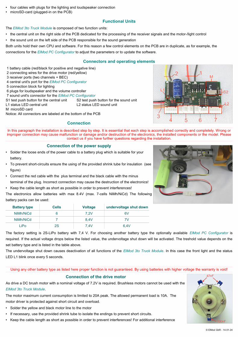
Connectors and operating elements 1 battery cable (red/black for positive and negative line) 2 connecting wires for the drive motor (red/yellow) 3 receiver ports (two channels + BEC) 4 central unit's port for the ElMod PC Configurator 5 connection block for lighting 6 plugs for loudspeaker and the volume controller 7 sound unit's connector for the ElMod PC ConfiguratorS1 test push button for the central unit S2 test push button for the sound unitL1 status LED central unit L2 status LED sound unitM microSD cardNotice: All connectors are labeled at the bottom of the PCB
ConnectionIn this paragraph the installation is described step by step. It is essential that each step is accomplished correctly and completely. Wrong or improper connection may cause malfunction or damage and/or destruction of the electronics, the installed components or the model. Please
contact us if you have further questions regarding the installation.
Connection of the power supply• Solder the loose ends of the power cable to a battery plug which is suitable for your
battery.• To prevent short-circuits ensure the using of the provided shrink tube for insulation (see
figure)• Connect the red cable with the plus terminal and the black cable with the minus
terminal of the plug. Incorrect connection may cause the destruction of the electronics!• Keep the cable length as short as possible in order to prevent interferences!The electronics allow batteries with max 8.4V (max. 7-cells NiMh/NiCd) The following battery packs can be used:
Battery type Cells Voltage undervoltage shut down
NiMh/NiCd 6 7,2V 6V
NiMh/NiCd 7 8,4V 7V
LiPo 2S 7,4V 6,4V
The factory setting is 2S-LiPo battery with 7,4 V. For choosing another battery type the optionally available ElMod PC Configurator is
required. If the actual voltage drops below the listed value, the undervoltage shut down will be activated. The treshold value depends on the set battery type and is listed in the table above.The undervoltage shut down causes deactivation of all functions of the ElMod 3to Truck Module. In this case the front light and the status
LED L1 blink once every 5 seconds.
Using any other battery type as listed here proper function is not guaranteed. By using batteries with higher voltage the warranty is void!
Connection of the drive motorAs drive a DC brush motor with a nominal voltage of 7.2V is required. Brushless motors cannot be used with the
ElMod 3to Truck Module.
The motor maximum current consumption is limited to 20A peak. The allowed permanent load is 10A. The motor driver is protected against short circuit and overload.
• Solder the yellow and black motor line to the motor• If necessary, use the provided shrink tube to isolate the endings to prevent short circuits.• Keep the cable length as short as possible in order to prevent interferences! For additional interference
© ElMod GbR - 14-01-24
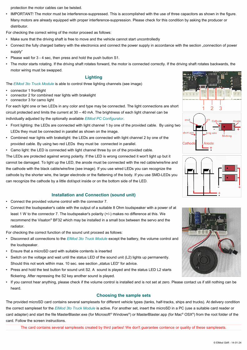
protection the motor cables can be twisted.• IMPORTANT! The motor must be interference-suppressed. This is accomplished with the use of three capacitors as shown in the figure.
Many motors are already equipped with proper interference-suppression. Please check for this condition by asking the producer or distributor.
For checking the correct wiring of the motor proceed as follows:
• Make sure that the driving shaft is free to move and the vehicle cannot start uncontrolledly• Connect the fully charged battery with the electronics and connect the power supply in accordance with the section „connection of power
supply“• Please wait for 3 - 4 sec, then press and hold the push button S1.• The motor starts rotating. If the driving shaft rotates forward, the motor is connected correctly. If the driving shaft rotates backwards, the
motor wiring must be swapped.
LightingThe ElMod 3to Truck Module is able to control three lighting channels (see image)
• connector 1 frontlight• connector 2 for combined rear lights with brakelight• connector 3 for camo light For each light one or two LEDs in any color and type may be connected. The light connections are short circuit protected and limits the current at 30 – 40 mA. The brightness of each light channel can be
individually adjusted by the optionally available ElMod PC Configurator.
• Front lighting: the LEDs are connected with light channel 1 by one of the provided cable. By using two LEDs they must be connected in parallel as shown on the image.
• Combined rear lights with brakelight: the LEDs are connected with light channel 2 by one of the provided cable. By using two red LEDs they must be connected in parallel.
• Camo light: the LED is connected with light channel three by on of the provided cable.The LEDs are protected against wrong polarity. If the LED is wrong connected it won't light up but it cannot be damaged. To light up the LED, the anode must be connected with the red cable/wire/line and the cathode with the black cable/wire/line (see image). If you use wired LEDs you can recognize the cathode by the shorter wire, the larger electrode or the flattening of the body. If you use SMD-LEDs you can recognize the cathode by a little dot/spot inside or on the bottom side of the LED.
Installation and Connection (sound unit)• Connect the provided volume control with the connector 7.• Connect the loudspeaker's cable with the output of a suitable 8 Ohm loudspeaker with a power of at
least 1 W to the connector 7. The loudspeaker's polarity (+/-) makes no difference at this. We recommend the Visaton® BF32 which may be installed in a small box between the servo and the radiator.
For checking the correct function of the sound unit proceed as follows:• Disconnect all connections to the ElMod 3to Truck Module except the battery, the volume control and
the loudspeaker.• Ensure that a microSD card with suitable contents is inserted• Switch on the voltage and wait until the status LED of the sound unit (L2) lights up permanently.
Should this not work within max. 10 sec. see section „status LED“ for advice.• Press and hold the test button for sound unit S2. A sound is played and the status LED L2 starts
flickering. After repressing the S2 key another sound is played.• If you cannot hear anything, please check if the volume control is installed and is not set at zero. Please contact us if still nothing can be
heard.
Choosing the sample setsThe provided microSD card contains several samplesets for different vehicle types (tanks, half-tracks, ships and trucks). At delivery condition
the correct sampleset for the ElMod 3to Truck Module is active. For another set, insert the microSD in a PC (use a suitable card reader or
card adapter) and start the file MasterBlaster.exe (for Microsoft® Windows®) or MasterBlaster.app (for Mac® OSX®) from the root folder of the card. Follow the screen instructions.
The card contains several samplesets created by third parties! We don't guarantee contence or quality of these samplesets.
© ElMod GbR - 14-01-24
RC receiver and servo connectionThe ElMod 3to Truck Module may be used either with two or three channel radio, whereby
one channel is dedicated to the steering servo. The number of connected channels is de-termined automatically. For the channels' identification and the correct function all mixers in the radio must be deactivated, the servo deflection must be to 100% and the trimming must be centered. Please contact us, if you have problems with the identification and the
operation of your radio with the ElMod 3to Truck Module. In the majority of cases the
reason is detected and fixed easily by our also on loan available tool Proptester. The op-tional channel 3 must be available as knob/slider or as a three way switch (top-center-
bottom). Otherwise not all possible functions may be used. The ElMod 3to Truck Module
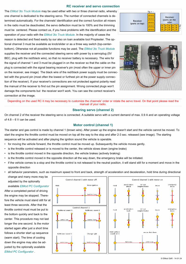
supplies the receiver and the connected steering servo with power by a servoplug (5V BEC, plug with the red/black wire), so that no receiver battery is necessary. The wire for the signal of channel 1 and 3 must be plugged in on the receiver so that the cable on the plug is connected with the signal bearing receiver's pin (most often the upper or inner pin on the receiver, see image) The black wire of the red/black power supply must be connec-ted with the ground pin (most often the lowest or furthest pin at the power supply connec-tion of the receiver). If your receiver's connections are not protected against polarity read the manual of the receiver to find out the pin assignment. Wrong connected plugs won't damage the components but the receiver won't work. You can see the correct receiver's connection at the image.
Depending on the used RC it may be necessary to customize the channels' order or rotate the servo travel. On that point please read the manual of your radio.
Steering servo (channel 2)On channel 2 of the receiver the steering servo is connected. A suitable servo with a current demand of max. 0.9 A and an operating voltage of 4.8 – 6 V can be used.
Motor control (channel 1)The starter and gas control is made by channel 1 (brown wire). After power up the engine doesn't start and the vehicle cannot be moved. To start the engine the throttle control must be moved on top all the way to the stop and after 2-3 sec. released (see image). The starting sequence will be activated and after playing the ignition sound the vehicle is operable.• for moving the vehicle forward, the throttle control must be moved up. Subsequently the vehicle moves gently.• is the throttle control released or is moved to the center, the vehicle slows down (engine brake)• is the throttle control moved in the opposite direction, the vehicle brakes (actively braking)• is the throttle control moved in the opposite direction all the way down, the emergency brake will be initiated.• if the vehicle comes to a stop and the throttle control is not released to the neutral position, it will stand still for a moment and move in the
opposite direction• all behavior parameters, such as maximum speed to front and back, strength of acceleration and deceleration, hold time during directional
change and many more may be adjusted by the optionally
available ElMod PC Configurator
After a completed period of driving the engine may be stopped. There-fore the vehicle must stand still for at least three seconds. After that the throttle control must must be put to the bottom quickly and back to the center. This procedure may not last longer the one second. Is the motor started again after just a short time follows a shorter start up sequence (warm start). The time of cooling down the engine may also be ad-justed by the optionally available
ElMod PC Configurator .
© ElMod GbR - 14-01-24
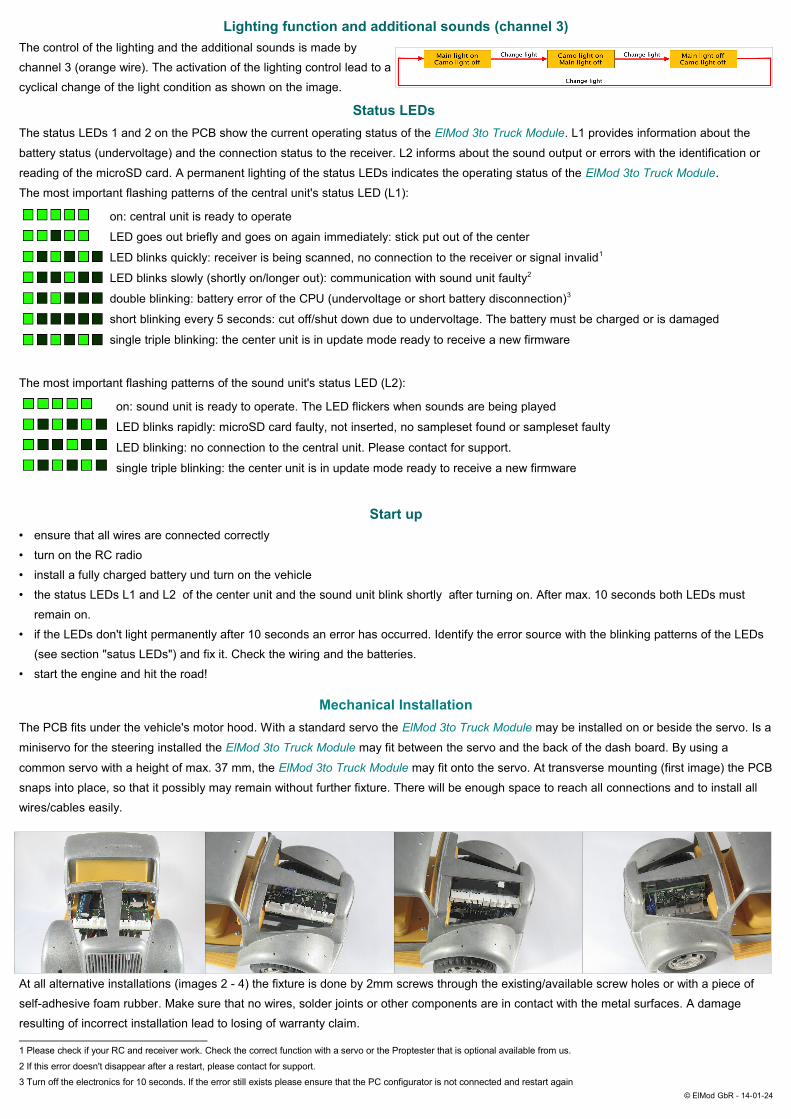
Lighting function and additional sounds (channel 3)The control of the lighting and the additional sounds is made by channel 3 (orange wire). The activation of the lighting control lead to a cyclical change of the light condition as shown on the image.
Status LEDs The status LEDs 1 and 2 on the PCB show the current operating status of the ElMod 3to Truck Module. L1 provides information about the
battery status (undervoltage) and the connection status to the receiver. L2 informs about the sound output or errors with the identification or
reading of the microSD card. A permanent lighting of the status LEDs indicates the operating status of the ElMod 3to Truck Module.
The most important flashing patterns of the central unit's status LED (L1):
on: central unit is ready to operate
LED goes out briefly and goes on again immediately: stick put out of the center
LED blinks quickly: receiver is being scanned, no connection to the receiver or signal invalid1
LED blinks slowly (shortly on/longer out): communication with sound unit faulty2
double blinking: battery error of the CPU (undervoltage or short battery disconnection)3
short blinking every 5 seconds: cut off/shut down due to undervoltage. The battery must be charged or is damaged
single triple blinking: the center unit is in update mode ready to receive a new firmware
The most important flashing patterns of the sound unit's status LED (L2):
on: sound unit is ready to operate. The LED flickers when sounds are being played
LED blinks rapidly: microSD card faulty, not inserted, no sampleset found or sampleset faulty
LED blinking: no connection to the central unit. Please contact for support.
single triple blinking: the center unit is in update mode ready to receive a new firmware
Start up• ensure that all wires are connected correctly• turn on the RC radio• install a fully charged battery und turn on the vehicle• the status LEDs L1 and L2 of the center unit and the sound unit blink shortly after turning on. After max. 10 seconds both LEDs must
remain on.• if the LEDs don't light permanently after 10 seconds an error has occurred. Identify the error source with the blinking patterns of the LEDs
(see section "satus LEDs") and fix it. Check the wiring and the batteries.• start the engine and hit the road!
Mechanical InstallationThe PCB fits under the vehicle's motor hood. With a standard servo the ElMod 3to Truck Module may be installed on or beside the servo. Is a
miniservo for the steering installed the ElMod 3to Truck Module may fit between the servo and the back of the dash board. By using a
common servo with a height of max. 37 mm, the ElMod 3to Truck Module may fit onto the servo. At transverse mounting (first image) the PCB
snaps into place, so that it possibly may remain without further fixture. There will be enough space to reach all connections and to install all wires/cables easily.
At all alternative installations (images 2 - 4) the fixture is done by 2mm screws through the existing/available screw holes or with a piece of self-adhesive foam rubber. Make sure that no wires, solder joints or other components are in contact with the metal surfaces. A damage resulting of incorrect installation lead to losing of warranty claim.
1 Please check if your RC and receiver work. Check the correct function with a servo or the Proptester that is optional available from us.
2 If this error doesn't disappear after a restart, please contact for support.
3 Turn off the electronics for 10 seconds. If the error still exists please ensure that the PC configurator is not connected and restart again© ElMod GbR - 14-01-24

Firmware update and configuration With the the optionally available ElMod PC Configurator it is possible to
connect the electronics to a PC for configuration. With the freely available software for Microsoft® Windows® PCs (Mac® OSX® version available on request) a great number of paramters maybe adjusted and information about the operating status can be received. Furthermore firmware
updates of the ElMod 3to Truck Module may be transferred and installed.
Please notice that the software needs direct access to the USB hardware. It may be necessary to run it in Administrator context. Also please ensure that your virus protection software doesn't block the USB hardware's access.
For updating the center unit's firmware the ElMod PC Configurator must
be connected with connector 4. To run the firmware update turn off the PCB's power supply. Press and hold the key S1. Now turn on the power supply again. The triple blinking of the status LED L1 indicates the operation status of the sound unit to receive the update. Please start the
ElMod PC Configurator software and press the red button "update"
For updating the sound unit's firmware the ElMod PC Configurator must
be connected with connector 7. To run the firmware update turn off the PCB's power supply. Press and hold the key S2. Now turn on the power supply again. The triple blinking of the status LED L2 indicates the operation status of the sound unit to receive the update. Please start the
ElMod PC Configurator software and press the red button "update"
Configuration and tweakingFor configurating the center unit the ElMod PC Configurator must be connected with connector 4. Turn on the PCB's power supply and start
the ElMod PC Configurator software suite. The ElMod 3to Truck will be found within just a few seconds and the current settings will be listed.
For further information about every parameter move the cursor to the parameter's name and wait 1 or 2 seconds. A more detailed text appears.
For configurating the sound unit the ElMod PC Configurator must be attached to connector 7. Turn on the PCB's power supply and start the
ElMod PC Configurator software. The ElMod 3to Truck will be found within just a few seconds and the current settings will be listed. For
further information about every parameter move the cursor to the parameter's name and wait 1 or 2 seconds. A more detailed text appears.
Nicht geeignet für Kinder unter 14 Jahren. Not suitable for Children under 14 years.Ne convient pas pour des enfants de moins de 14 ans. Niet geschikt voor kinderen onder de 14 jaar.
ElMod Thomas Kusch, M.Sc. & Jürgen K. Huber GbREnzenhardtweg 11D-72622 Nürtingen
ElMod Th. Kusch, M.Sc. & Jürgen K. Huber GbR [email protected] http://www.elmod.eu
© ElMod GbR - 14-01-24