Embed Size (px)
Citation preview

2338.4-071117
ELLIPTICAL
IMPORTANT: Read all instructions carefully before using this product. Retain this
owner’s manual for future reference. The specifications of this product may vary from
this photo and, subject to change without notice.

PLEASE DO NOT RETURN THIS PRODUCT TO THE STORE.
STOP. Contact customer service if you have any questions
regarding assembly or proper operation of the machine.
Email us at: [email protected]
Or call us at: 1-844-641-7920
Hours:
8:00 am to 5:00 pm (PST) Daily
1
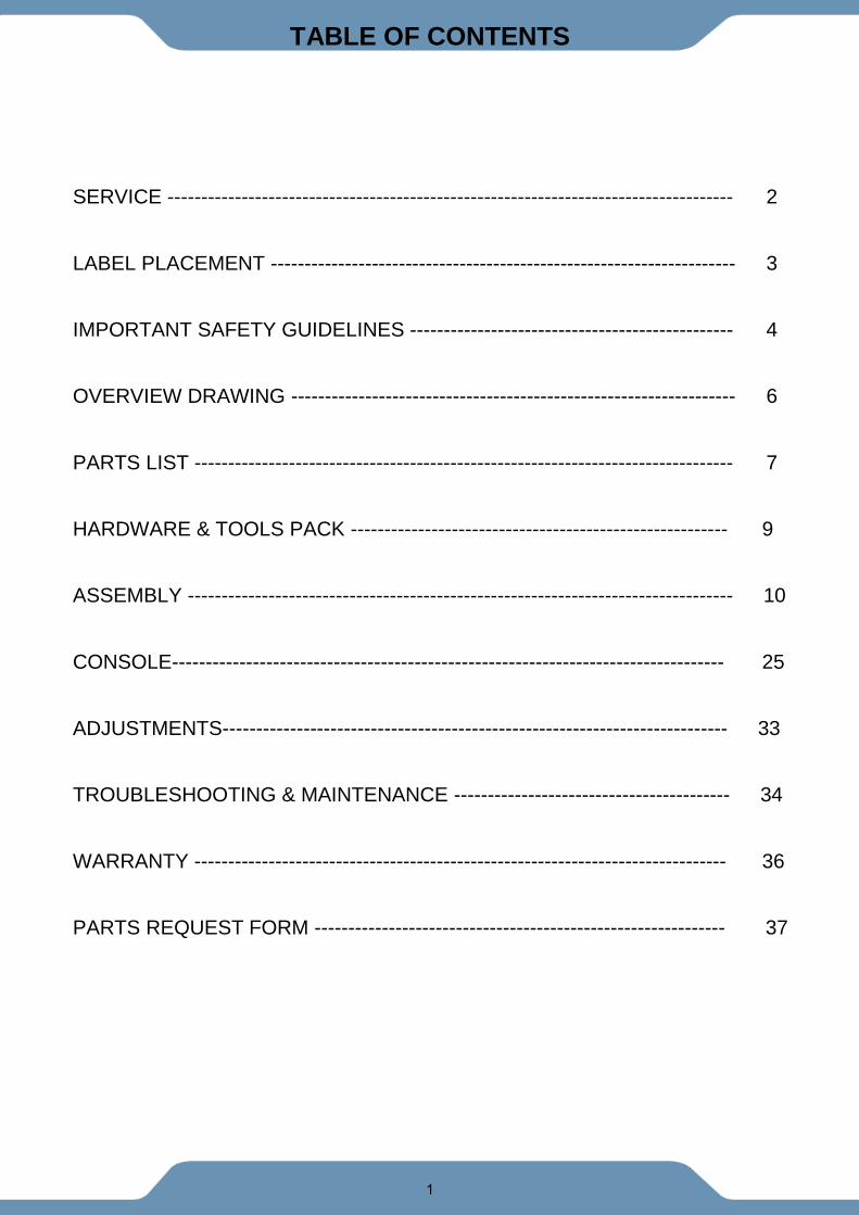
TABLE OF CONTENTS
SERVICE ------------------------------------------------------------------------------------ 2
LABEL PLACEMENT --------------------------------------------------------------------- 3
IMPORTANT SAFETY GUIDELINES ------------------------------------------------ 4
OVERVIEW DRAWING ------------------------------------------------------------------ 6
PARTS LIST -------------------------------------------------------------------------------- 7
HARDWARE & TOOLS PACK -------------------------------------------------------- 9
ASSEMBLY --------------------------------------------------------------------------------- 10
CONSOLE---------------------------------------------------------------------------------- 25
ADJUSTMENTS--------------------------------------------------------------------------- 33
TROUBLESHOOTING & MAINTENANCE ----------------------------------------- 34
WARRANTY ------------------------------------------------------------------------------- 36
PARTS REQUEST FORM ------------------------------------------------------------- 37

2
SERVICE
IMPORTANT: FOR NORTH AMERICA ONLY
For damaged or defective product, questions, replacement parts or any other service
support, please contact our customer service department by the below methods:
For The Best Service, please Email: [email protected] Response Time: 1-2 Business Days
Emailing us with the information above will be the best method to receive a response during
peak business hours
Website: www.paradigmhw.com
Toll-Free:
1-844-641-7920
(8:00 AM - 5:00 PM Pacific Standard Time, Daily)
Response time may vary via calling
Please have the following information ready when requesting for service:
• Your name
• Phone number
• Model number
• Serial number
• Part number
• Proof of Purchase
For damaged or defective product please contact our customer service before returning to
the store.
Paradigm Health & Wellness, Inc.
1189 Jellick Ave.
City of Industry, CA 91748, USA

3
LABEL PLACEMENT
4
IMPORTANT SAFETY GUIDELINES
Read all guidelines before using this machine. When using this machine,
basic precautions should always be followed, including the following:
WARNING - To reduce the risk of injury to persons:
1. Make sure your equipment is correctly assembled before you use it.
2. Be sure all screws, nuts, and bolts are tightened prior to use.
3. Before using this equipment, we recommend doing warm ups.
4. Only one person should be using the equipment at a time.
5. Never operate this Equipment if it is damaged, if it is not working properly, has been dropped, or
damaged. If a problem is encountered contact Customer Service before using the equipment
again.
6. Always use this equipment on a clear and level surface.
7. For household use only.
8. Do not use outdoors or near water.
9. Use the machine only for its intended use as described in this manual. Do not use attachments
not recommended by the manufacturer.
10. Do not wear loose clothing when using the equipment.
11. Never drop or insert any object into any opening.
12. If at any time you feel faint, light-headed, or dizziness while operating the equipment, stop
exercising immediately. You should also stop exercising if you are experiencing pain or any
discomfort.
13. For any problems contact customer service. Servicing should be performed by an authorized
service representative. Our contact number is on the service page.
14. This product requires a minimum of 6 square feet of space for safe operation.
15. Be careful to always hold onto the handlebars when you’re mounting and dismounting.
16. Be careful to have the pedals at their lowest point when stepping off.
17. Hold onto the handlebars and use both the pedals in tandem to ensure a smooth, effective
workout.
18. Warning: - Risk of Personal Injury - Consult with your personal physician to see if exercise
equipment is appropriate for you. This is especially important for people with pre-existing health
problems. Do not use this equipment without your physician's approval.
19. Warning: - Risk of Personal Injury – Do not allow children to use this machine.
20. Warning: - Risk of Personal Injury - Keep children under the age of 13 away from the
machine.
21. Warning: - Risk of Personal Injury – Keep body parts, hair, loose clothing, and jewelry
clear of all moving parts.
22. Warning: - Risk of Personal Injury - Do not attempt to service the unit yourself.
Discontinue use and contact customer service.
23. Warning: - To Reduce The Risk Of Personal Injury - Read And Understand All Read The
Instructions Before Using This Machine
5
The product weighs more than 44 lbs. It is heavily
recommended that at least 2 persons assemble.
IMPORTANT SAFETY GUIDELINES
Do not use this equipment if you have any of the following conditions or ailments:
• Pregnancy
• Extreme obesity
• Middle ear infection
• Hiatus hernia or Ventral hernia
• Glaucoma, retinal detachment or conjunctivitis
• Use of anticoagulants including Aspirin in high doses.
• Spinal injury, Cerebral Sclerosis, or acutely swollen joints
• Heart or circulatory disorders for which you are being treated
• High blood pressure, Hypertension, Recent stroke or Transient Ischemic attack
• Bone weaknesses including Osteoporosis, Unhealed fractures, Modular pins, or surgically
implanted orthopedic supports.
DO NOT EXCEED THE MAXIMUM RATED WEIGHT CAPACITY
The Maximum Weight Capacity for this product is 270 lbs/123 kgs.
RETAIN THIS OWNER’S MANUAL AND KEEP THE ORIGINAL PURCHASE RECEIPT FOR FUTURE
REFERENCE. &
SAVE THESE GUIDELINES
!

6
OVERVIEW DRAWING
7
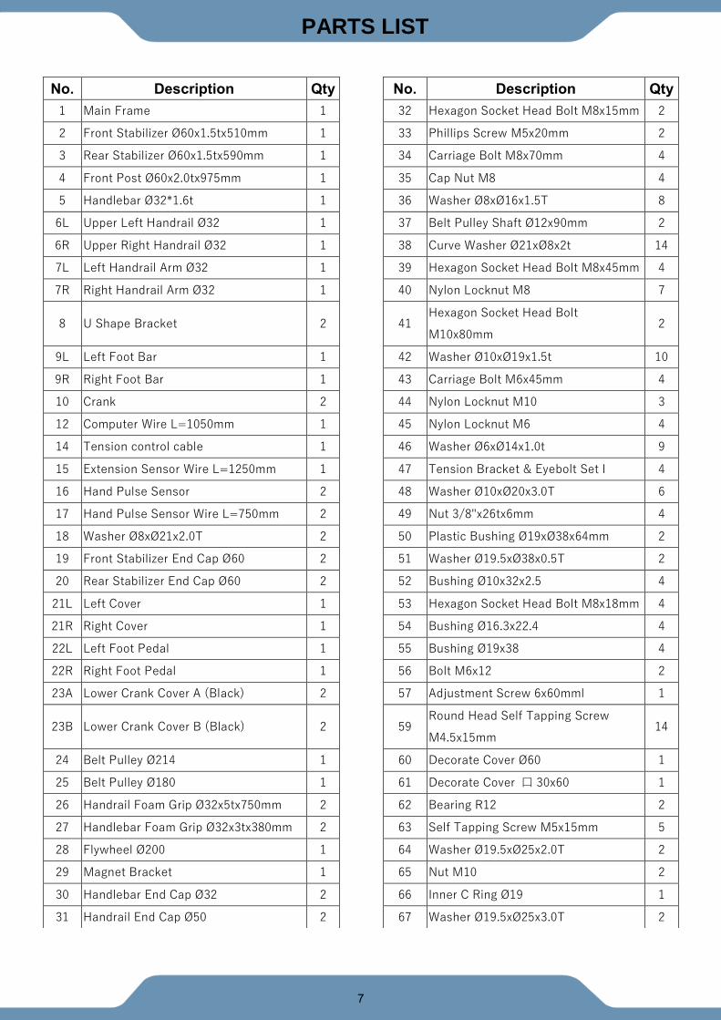
PARTS LIST
No. Description Qty No. Description Qty
1 Main Frame 1 32 Hexagon Socket Head Bolt M8x15mm 2
2 Front Stabilizer Ø60x1.5tx510mm 1 33 Phillips Screw M5x20mm 2
3 Rear Stabilizer Ø60x1.5tx590mm 1 34 Carriage Bolt M8x70mm 4
4 Front Post Ø60x2.0tx975mm 1 35 Cap Nut M8 4
5 Handlebar Ø32*1.6t 1 36 Washer Ø8xØ16x1.5T 8
6L Upper Left Handrail Ø32 1 37 Belt Pulley Shaft Ø12x90mm 2
6R Upper Right Handrail Ø32 1 38 Curve Washer Ø21xØ8x2t 14
7L Left Handrail Arm Ø32 1 39 Hexagon Socket Head Bolt M8x45mm 4
7R Right Handrail Arm Ø32 1 40 Nylon Locknut M8 7
8 U Shape Bracket 2
41 Hexagon Socket Head Bolt
M10x80mm 2
9L Left Foot Bar 1 42 Washer Ø10xØ19x1.5t 10
9R Right Foot Bar 1 43 Carriage Bolt M6x45mm 4
10 Crank 2 44 Nylon Locknut M10 3
12 Computer Wire L=1050mm 1 45 Nylon Locknut M6 4
14 Tension control cable 1 46 Washer Ø6xØ14x1.0t 9
15 Extension Sensor Wire L=1250mm 1 47 Tension Bracket & Eyebolt Set I 4
16 Hand Pulse Sensor 2 48 Washer Ø10xØ20x3.0T 6
17 Hand Pulse Sensor Wire L=750mm 2 49 Nut 3/8"x26tx6mm 4
18 Washer Ø8xØ21x2.0T 2 50 Plastic Bushing Ø19xØ38x64mm 2
19 Front Stabilizer End Cap Ø60 2 51 Washer Ø19.5xØ38x0.5T 2
20 Rear Stabilizer End Cap Ø60 2 52 Bushing Ø10x32x2.5 4
21L Left Cover 1 53 Hexagon Socket Head Bolt M8x18mm 4
21R Right Cover 1 54 Bushing Ø16.3x22.4 4
22L Left Foot Pedal 1 55 Bushing Ø19x38 4
22R Right Foot Pedal 1 56 Bolt M6x12 2
23A Lower Crank Cover A (Black) 2 57 Adjustment Screw 6x60mml 1
23B Lower Crank Cover B (Black) 2
59 Round Head Self Tapping Screw
M4.5x15mm 14
24 Belt Pulley Ø214 1 60 Decorate Cover Ø60 1
25 Belt Pulley Ø180 1 61 Decorate Cover 口 30x60 1
26 Handrail Foam Grip Ø32x5tx750mm 2 62 Bearing R12 2
27 Handlebar Foam Grip Ø32x3tx380mm 2 63 Self Tapping Screw M5x15mm 5
28 Flywheel Ø200 1 64 Washer Ø19.5xØ25x2.0T 2
29 Magnet Bracket 1 65 Nut M10 2
30 Handlebar End Cap Ø32 2 66 Inner C Ring Ø19 1
31 Handrail End Cap Ø50 2 67 Washer Ø19.5xØ25x3.0T 2
8
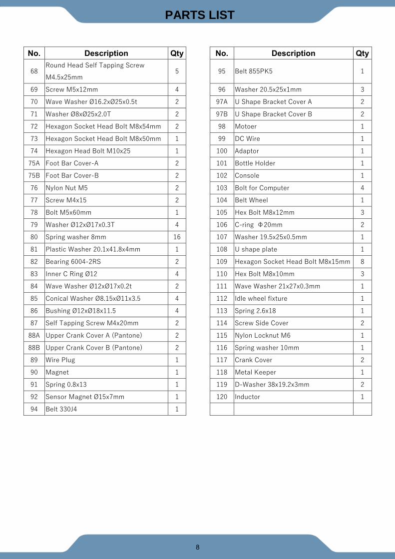
PARTS LIST
No. Description Qty No. Description Qty
68 Round Head Self Tapping Screw
M4.5x25mm 5
95 Belt 855PK5 1
69 Screw M5x12mm 4 96 Washer 20.5x25x1mm 3
70 Wave Washer Ø16.2xØ25x0.5t 2 97A U Shape Bracket Cover A 2
71 Washer Ø8xØ25x2.0T 2 97B U Shape Bracket Cover B 2
72 Hexagon Socket Head Bolt M8x54mm 2 98 Motoer 1
73 Hexagon Socket Head Bolt M8x50mm 1 99 DC Wire 1
74 Hexagon Head Bolt M10x25 1 100 Adaptor 1
75A Foot Bar Cover-A 2 101 Bottle Holder 1
75B Foot Bar Cover-B 2 102 Console 1
76 Nylon Nut M5 2 103 Bolt for Computer 4
77 Screw M4x15 2 104 Belt Wheel 1
78 Bolt M5x60mm 1 105 Hex Bolt M8x12mm 3
79 Washer Ø12xØ17x0.3T 4 106 C-ring Φ20mm 2
80 Spring washer 8mm 16 107 Washer 19.5x25x0.5mm 1
81 Plastic Washer 20.1x41.8x4mm 1 108 U shape plate 1
82 Bearing 6004-2RS 2 109 Hexagon Socket Head Bolt M8x15mm 8
83 Inner C Ring Ø12 4 110 Hex Bolt M8x10mm 3
84 Wave Washer Ø12xØ17x0.2t 2 111 Wave Washer 21x27x0.3mm 1
85 Conical Washer Ø8.15xØ11x3.5 4 112 Idle wheel fixture 1
86 Bushing Ø12xØ18x11.5 4 113 Spring 2.6x18 1
87 Self Tapping Screw M4x20mm 2 114 Screw Side Cover 2
88A Upper Crank Cover A (Pantone) 2 115 Nylon Locknut M6 1
88B Upper Crank Cover B (Pantone) 2 116 Spring washer 10mm 1
89 Wire Plug 1 117 Crank Cover 2
90 Magnet 1 118 Metal Keeper 1
91 Spring 0.8x13 1 119 D-Washer 38x19.2x3mm 2
92 Sensor Magnet Ø15x7mm 1 120 Inductor 1
94 Belt 330J4 1
9
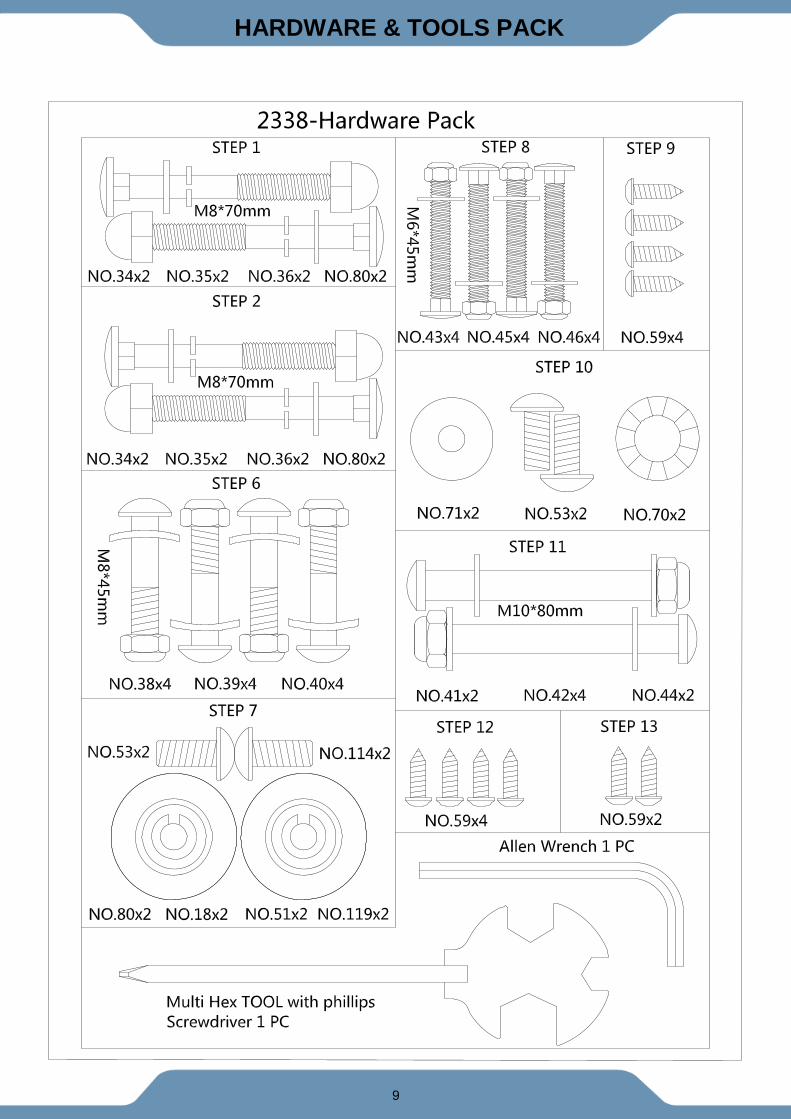
HARDWARE & TOOLS PACK
10
ASSEMBLY
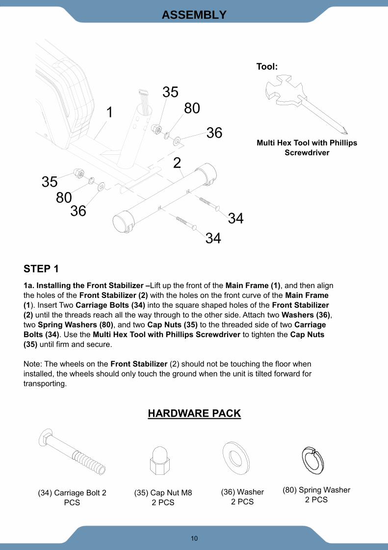
STEP 1
1a. Installing the Front Stabilizer –Lift up the front of the Main Frame (1), and then align
the holes of the Front Stabilizer (2) with the holes on the front curve of the Main Frame
(1). Insert Two Carriage Bolts (34) into the square shaped holes of the Front Stabilizer
(2) until the threads reach all the way through to the other side. Attach two Washers (36),
two Spring Washers (80), and two Cap Nuts (35) to the threaded side of two Carriage
Bolts (34). Use the Multi Hex Tool with Phillips Screwdriver to tighten the Cap Nuts
(35) until firm and secure.
Note: The wheels on the Front Stabilizer (2) should not be touching the floor when
installed, the wheels should only touch the ground when the unit is tilted forward for
transporting.
HARDWARE PACK
Tool:
Multi Hex Tool with Phillips
Screwdriver
(34) Carriage Bolt 2
PCS
(36) Washer
2 PCS
(35) Cap Nut M8
2 PCS
(80) Spring Washer
2 PCS
11
ASSEMBLY
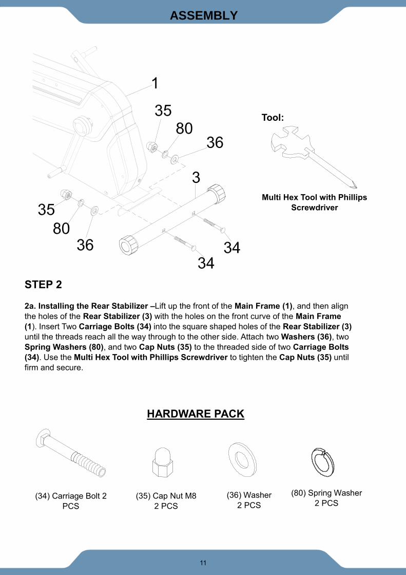
STEP 2
2a. Installing the Rear Stabilizer –Lift up the front of the Main Frame (1), and then align
the holes of the Rear Stabilizer (3) with the holes on the front curve of the Main Frame
(1). Insert Two Carriage Bolts (34) into the square shaped holes of the Rear Stabilizer (3)
until the threads reach all the way through to the other side. Attach two Washers (36), two
Spring Washers (80), and two Cap Nuts (35) to the threaded side of two Carriage Bolts
(34). Use the Multi Hex Tool with Phillips Screwdriver to tighten the Cap Nuts (35) until
firm and secure.
Tool:
Multi Hex Tool with Phillips
Screwdriver
(34) Carriage Bolt 2
PCS
(36) Washer
2 PCS
(35) Cap Nut M8
2 PCS
(80) Spring Washer
2 PCS
HARDWARE PACK
12
ASSEMBLY
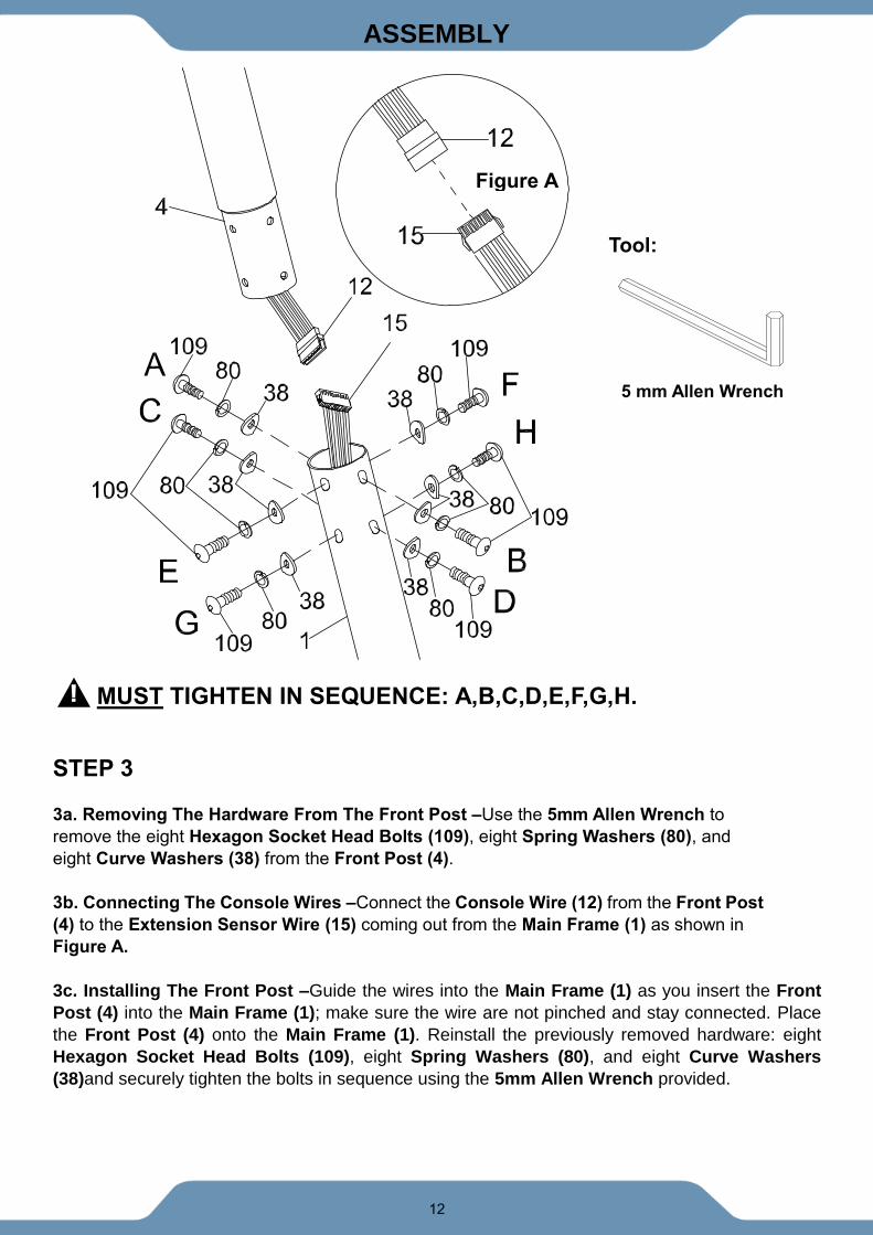
MUST TIGHTEN IN SEQUENCE: A,B,C,D,E,F,G,H.
STEP 3
3a. Removing The Hardware From The Front Post –Use the 5mm Allen Wrench to
remove the eight Hexagon Socket Head Bolts (109), eight Spring Washers (80), and
eight Curve Washers (38) from the Front Post (4).
3b. Connecting The Console Wires –Connect the Console Wire (12) from the Front Post
(4) to the Extension Sensor Wire (15) coming out from the Main Frame (1) as shown in
Figure A.
3c. Installing The Front Post –Guide the wires into the Main Frame (1) as you insert the Front
Post (4) into the Main Frame (1); make sure the wire are not pinched and stay connected. Place
the Front Post (4) onto the Main Frame (1). Reinstall the previously removed hardware: eight
Hexagon Socket Head Bolts (109), eight Spring Washers (80), and eight Curve Washers
(38)and securely tighten the bolts in sequence using the 5mm Allen Wrench provided.
5 mm Allen Wrench
Tool:
!
Figure A
13
ASSEMBLY
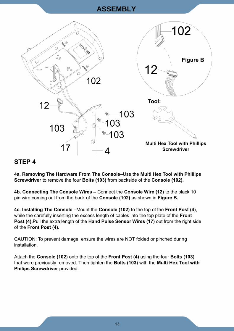
STEP 4
4a. Removing The Hardware From The Console–Use the Multi Hex Tool with Phillips
Screwdriver to remove the four Bolts (103) from backside of the Console (102).
4b. Connecting The Console Wires – Connect the Console Wire (12) to the black 10
pin wire coming out from the back of the Console (102) as shown in Figure B.
4c. Installing The Console –Mount the Console (102) to the top of the Front Post (4),
while the carefully inserting the excess length of cables into the top plate of the Front
Post (4).Pull the extra length of the Hand Pulse Sensor Wires (17) out from the right side
of the Front Post (4).
CAUTION: To prevent damage, ensure the wires are NOT folded or pinched during
installation.
Attach the Console (102) onto the top of the Front Post (4) using the four Bolts (103)
that were previously removed. Then tighten the Bolts (103) with the Multi Hex Tool with
Philips Screwdriver provided.
Tool:
Multi Hex Tool with Phillips
Screwdriver
Figure B
14
ASSEMBLY
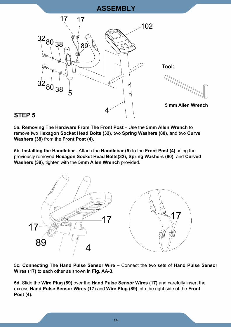
STEP 5
5a. Removing The Hardware From The Front Post – Use the 5mm Allen Wrench to
remove two Hexagon Socket Head Bolts (32), two Spring Washers (80), and two Curve
Washers (38) from the Front Post (4).
5b. Installing the Handlebar –Attach the Handlebar (5) to the Front Post (4) using the
previously removed Hexagon Socket Head Bolts(32), Spring Washers (80), and Curved
Washers (38), tighten with the 5mm Allen Wrench provided.
5c. Connecting The Hand Pulse Sensor Wire – Connect the two sets of Hand Pulse Sensor
Wires (17) to each other as shown in Fig. AA-3.
5d. Slide the Wire Plug (89) over the Hand Pulse Sensor Wires (17) and carefully insert the
excess Hand Pulse Sensor Wires (17) and Wire Plug (89) into the right side of the Front
Post (4).
5 mm Allen Wrench
Tool:
15
ASSEMBLY
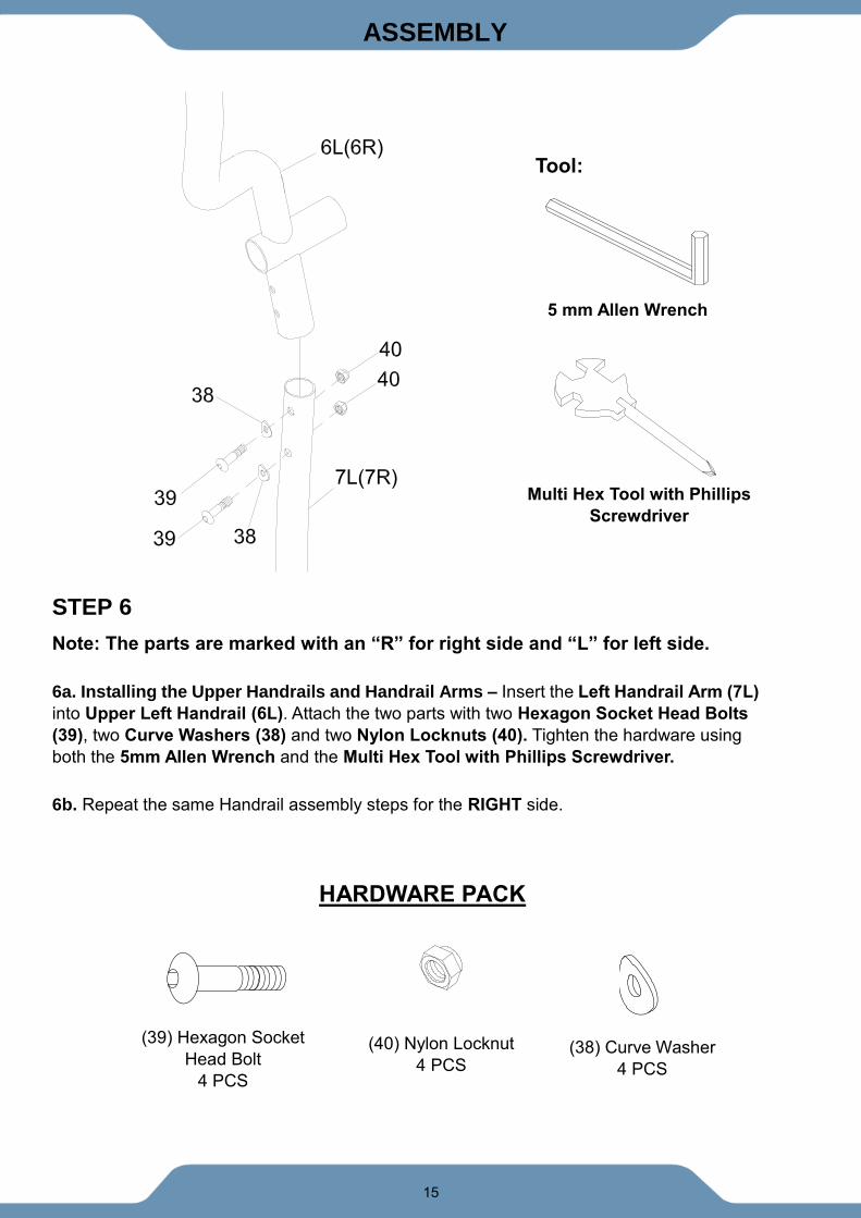
STEP 6
Note: The parts are marked with an “R” for right side and “L” for left side.
6a. Installing the Upper Handrails and Handrail Arms – Insert the Left Handrail Arm (7L)
into Upper Left Handrail (6L). Attach the two parts with two Hexagon Socket Head Bolts
(39), two Curve Washers (38) and two Nylon Locknuts (40). Tighten the hardware using
both the 5mm Allen Wrench and the Multi Hex Tool with Phillips Screwdriver.
6b. Repeat the same Handrail assembly steps for the RIGHT side.
5 mm Allen Wrench
Tool:
Multi Hex Tool with Phillips
Screwdriver
(40) Nylon Locknut
4 PCS
(38) Curve Washer
4 PCS
(39) Hexagon Socket
Head Bolt
4 PCS
HARDWARE PACK

16
ASSEMBLY
STEP 7
Note: The parts are marked with an “R” for right side and “L” for left side. 7a. Installing the Upper Handrails and Front Post – Install the Plastic Bushings (50) onto
both sides of the posts on the Front Post (4). Then insert a Washer (51) on each side.
Insert the Upper Left/Right Handrails (6L, 6R) onto their corresponding sides on the Front
Post (4). Insert one Hexagon Socket Head Bolt (53), one Spring Washer (80), one Washer
(18) and one D Washer (119) into the central axis of Front Post (4). Tighten the hardware by
using the 5mm Allen Wrench until firm and secure.
Repeat the same assembly steps for installing the Upper Right Handrail (6R) onto the Front
Post (4).
5 mm Allen Wrench
Tool:
(119) D Washer
2 PCS
(51) Washer
2 PCS
(18) Washer
2 PCS
(53) Hexagon Socket
Head Bolt
2 PCS
(80) Spring Washer
2 PCS
HARDWARE PACK
17
ASSEMBLY
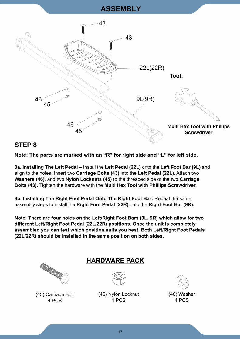
STEP 8
Note: The parts are marked with an “R” for right side and “L” for left side. 8a. Installing The Left Pedal – Install the Left Pedal (22L) onto the Left Foot Bar (9L) and
align to the holes. Insert two Carriage Bolts (43) into the Left Pedal (22L). Attach two
Washers (46), and two Nylon Locknuts (45) to the threaded side of the two Carriage
Bolts (43). Tighten the hardware with the Multi Hex Tool with Phillips Screwdriver.
8b. Installing The Right Foot Pedal Onto The Right Foot Bar: Repeat the same
assembly steps to install the Right Foot Pedal (22R) onto the Right Foot Bar (9R).
Note: There are four holes on the Left/Right Foot Bars (9L, 9R) which allow for two
different Left/Right Foot Pedal (22L/22R) positions. Once the unit is completely
assembled you can test which position suits you best. Both Left/Right Foot Pedals
(22L/22R) should be installed in the same position on both sides.
HARDWARE PACK
Tool:
Multi Hex Tool with Phillips
Screwdriver
(43) Carriage Bolt
4 PCS
(45) Nylon Locknut
4 PCS
(46) Washer
4 PCS
18
ASSEMBLY
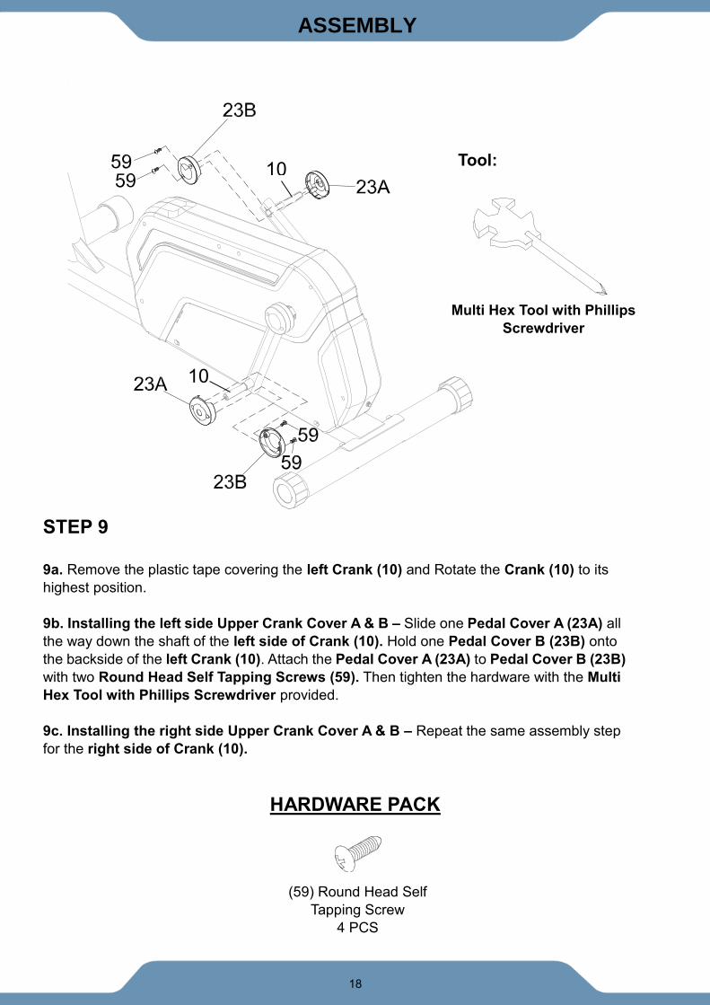
STEP 9
9a. Remove the plastic tape covering the left Crank (10) and Rotate the Crank (10) to its
highest position.
9b. Installing the left side Upper Crank Cover A & B – Slide one Pedal Cover A (23A) all
the way down the shaft of the left side of Crank (10). Hold one Pedal Cover B (23B) onto
the backside of the left Crank (10). Attach the Pedal Cover A (23A) to Pedal Cover B (23B)
with two Round Head Self Tapping Screws (59). Then tighten the hardware with the Multi
Hex Tool with Phillips Screwdriver provided.
9c. Installing the right side Upper Crank Cover A & B – Repeat the same assembly step
for the right side of Crank (10).
HARDWARE PACK
Tool:
Multi Hex Tool with Phillips
Screwdriver
10
10
(59) Round Head Self
Tapping Screw
4 PCS
19
ASSEMBLY
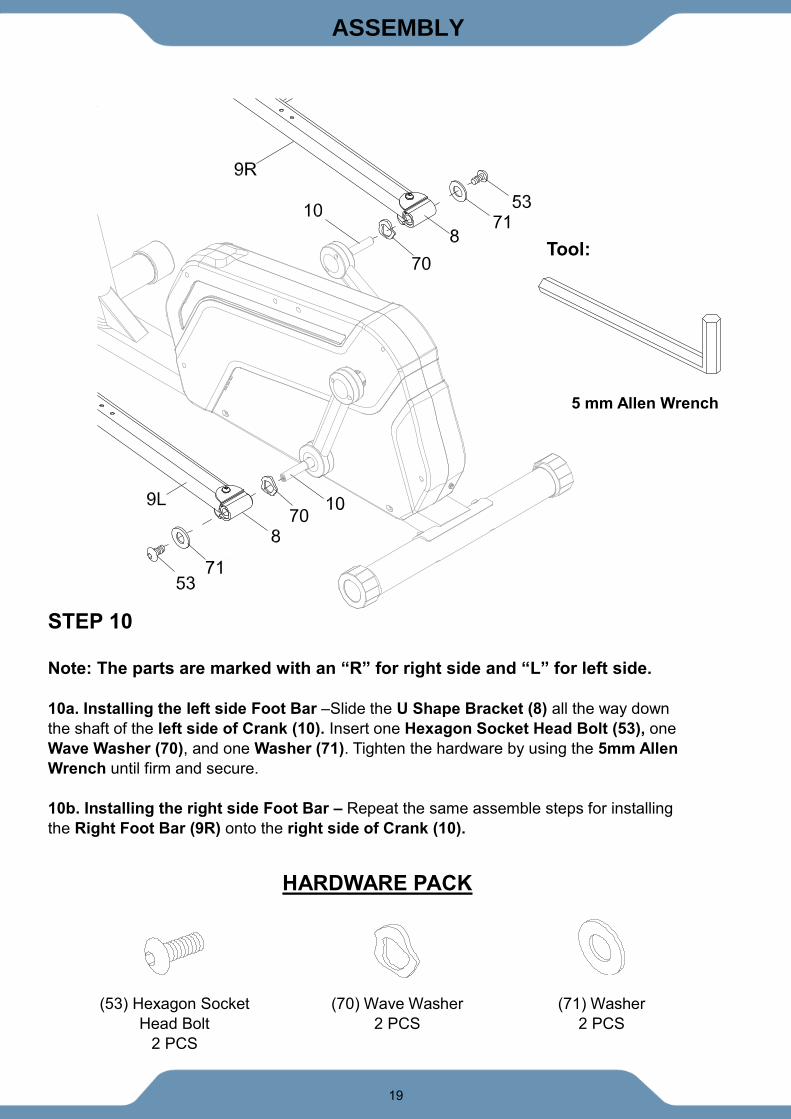
STEP 10
Note: The parts are marked with an “R” for right side and “L” for left side. 10a. Installing the left side Foot Bar –Slide the U Shape Bracket (8) all the way down
the shaft of the left side of Crank (10). Insert one Hexagon Socket Head Bolt (53), one
Wave Washer (70), and one Washer (71). Tighten the hardware by using the 5mm Allen
Wrench until firm and secure.
10b. Installing the right side Foot Bar – Repeat the same assemble steps for installing
the Right Foot Bar (9R) onto the right side of Crank (10).
5 mm Allen Wrench
Tool:
(53) Hexagon Socket
Head Bolt
2 PCS
(70) Wave Washer
2 PCS
(71) Washer
2 PCS
HARDWARE PACK
20
ASSEMBLY
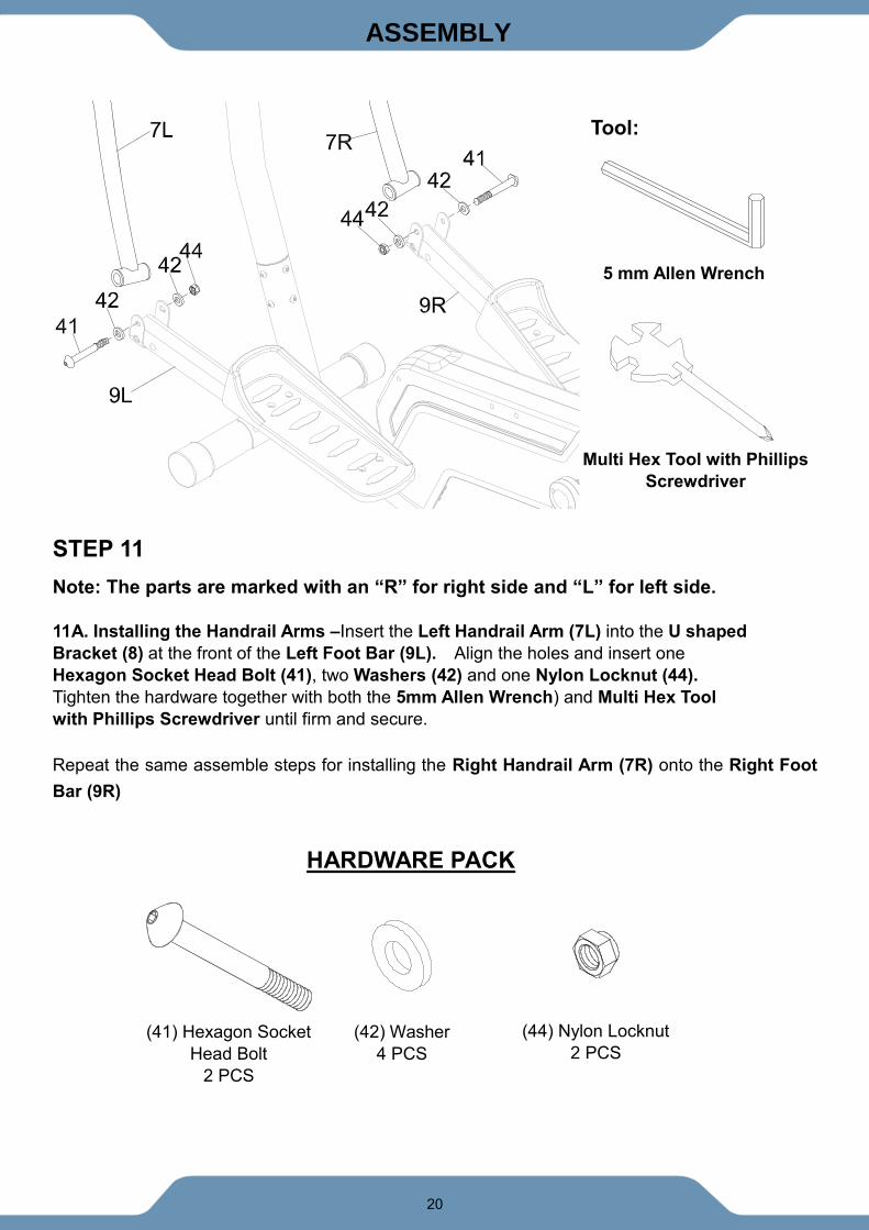
STEP 11
Note: The parts are marked with an “R” for right side and “L” for left side. 11A. Installing the Handrail Arms –Insert the Left Handrail Arm (7L) into the U shaped
Bracket (8) at the front of the Left Foot Bar (9L). Align the holes and insert one
Hexagon Socket Head Bolt (41), two Washers (42) and one Nylon Locknut (44).
Tighten the hardware together with both the 5mm Allen Wrench) and Multi Hex Tool
with Phillips Screwdriver until firm and secure.
Repeat the same assemble steps for installing the Right Handrail Arm (7R) onto the Right Foot
Bar (9R)
(41) Hexagon Socket
Head Bolt
2 PCS
(42) Washer
4 PCS
(44) Nylon Locknut
2 PCS
HARDWARE PACK
5 mm Allen Wrench
Tool:
Multi Hex Tool with Phillips
Screwdriver
21
ASSEMBLY
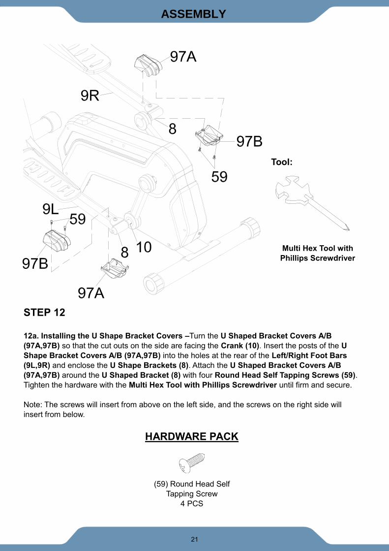
STEP 12
12a. Installing the U Shape Bracket Covers –Turn the U Shaped Bracket Covers A/B
(97A,97B) so that the cut outs on the side are facing the Crank (10). Insert the posts of the U
Shape Bracket Covers A/B (97A,97B) into the holes at the rear of the Left/Right Foot Bars
(9L,9R) and enclose the U Shape Brackets (8). Attach the U Shaped Bracket Covers A/B
(97A,97B) around the U Shaped Bracket (8) with four Round Head Self Tapping Screws (59).
Tighten the hardware with the Multi Hex Tool with Phillips Screwdriver until firm and secure.
Note: The screws will insert from above on the left side, and the screws on the right side will
insert from below.
Tool:
Multi Hex Tool with
Phillips Screwdriver
(59) Round Head Self
Tapping Screw
4 PCS
HARDWARE PACK
22
ASSEMBLY
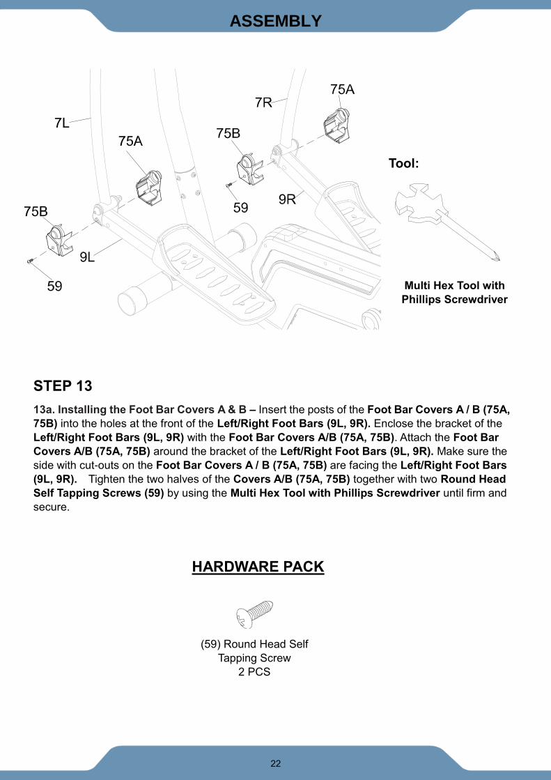
STEP 13
13a. Installing the Foot Bar Covers A & B – Insert the posts of the Foot Bar Covers A / B (75A,
75B) into the holes at the front of the Left/Right Foot Bars (9L, 9R). Enclose the bracket of the
Left/Right Foot Bars (9L, 9R) with the Foot Bar Covers A/B (75A, 75B). Attach the Foot Bar
Covers A/B (75A, 75B) around the bracket of the Left/Right Foot Bars (9L, 9R). Make sure the
side with cut-outs on the Foot Bar Covers A / B (75A, 75B) are facing the Left/Right Foot Bars
(9L, 9R). Tighten the two halves of the Covers A/B (75A, 75B) together with two Round Head
Self Tapping Screws (59) by using the Multi Hex Tool with Phillips Screwdriver until firm and
secure.
Tool:
Multi Hex Tool with
Phillips Screwdriver
(59) Round Head Self
Tapping Screw
2 PCS
HARDWARE PACK
23
ASSEMBLY
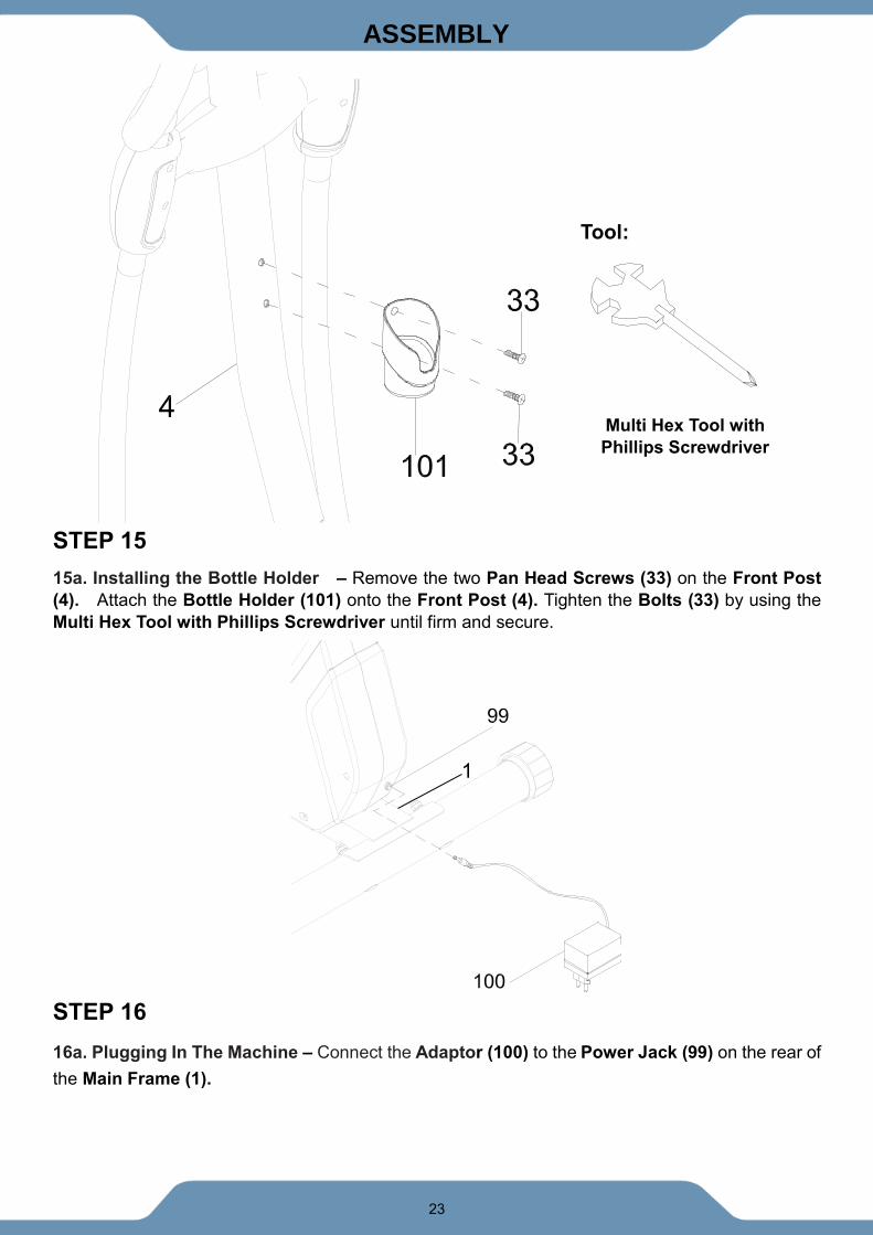
STEP 15
15a. Installing the Bottle Holder – Remove the two Pan Head Screws (33) on the Front Post
(4). Attach the Bottle Holder (101) onto the Front Post (4). Tighten the Bolts (33) by using the
Multi Hex Tool with Phillips Screwdriver until firm and secure.
STEP 16
16a. Plugging In The Machine – Connect the Adaptor (100) to the Power Jack (99) on the rear of
the Main Frame (1).
Tool:
Multi Hex Tool with
Phillips Screwdriver
1
24
CONSOLE
CONSOLE
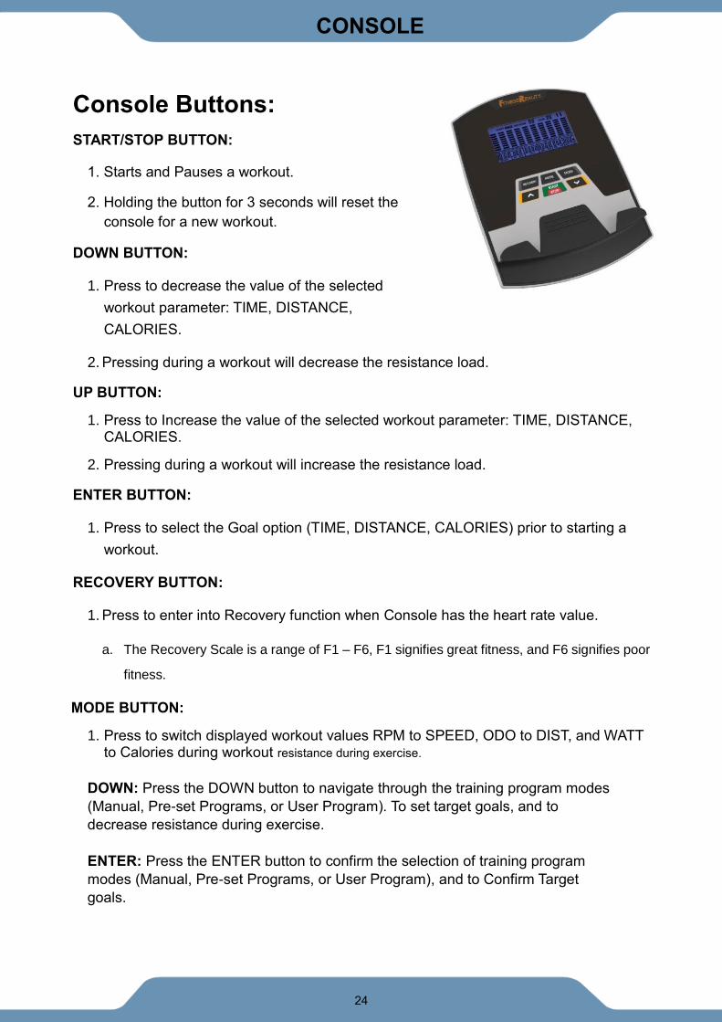
Console Buttons:
START/STOP BUTTON:
1. Starts and Pauses a workout.
2. Holding the button for 3 seconds will reset the
console for a new workout.
DOWN BUTTON:
1. Press to decrease the value of the selected
workout parameter: TIME, DISTANCE,
CALORIES.
2. Pressing during a workout will decrease the resistance load.
UP BUTTON:
1. Press to Increase the value of the selected workout parameter: TIME, DISTANCE, CALORIES.
2. Pressing during a workout will increase the resistance load.
ENTER BUTTON:
1. Press to select the Goal option (TIME, DISTANCE, CALORIES) prior to starting a
workout.
RECOVERY BUTTON:
1. Press to enter into Recovery function when Console has the heart rate value.
a. The Recovery Scale is a range of F1 – F6, F1 signifies great fitness, and F6 signifies poor
fitness.
MODE BUTTON:
1. Press to switch displayed workout values RPM to SPEED, ODO to DIST, and WATT to Calories during workout resistance during exercise.
DOWN: Press the DOWN button to navigate through the training program modes
(Manual, Pre-set Programs, or User Program). To set target goals, and to
decrease resistance during exercise.
ENTER: Press the ENTER button to confirm the selection of training program
modes (Manual, Pre-set Programs, or User Program), and to Confirm Target
goals.
25
CONSOLE
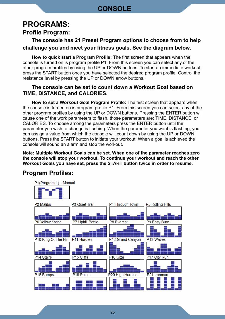
PROGRAMS: Profile Program:
The console has 21 Preset Program options to choose from to help
challenge you and meet your fitness goals. See the diagram below.
How to quick start a Program Profile: The first screen that appears when the console is turned on is program profile P1. From this screen you can select any of the other program profiles by using the UP or DOWN buttons. To start an immediate workout press the START button once you have selected the desired program profile. Control the resistance level by pressing the UP or DOWN arrow buttons.
The console can be set to count down a Workout Goal based on TIME, DISTANCE, and CALORIES.
How to set a Workout Goal Program Profile: The first screen that appears when the console is turned on is program profile P1. From this screen you can select any of the other program profiles by using the UP or DOWN buttons. Pressing the ENTER button will cause one of the work parameters to flash, those parameters are: TIME, DISTANCE, or CALORIES. To choose among the parameters press the ENTER button until the parameter you wish to change is flashing. When the parameter you want is flashing, you can assign a value from which the console will count down by using the UP or DOWN buttons. Press the START button to initiate your workout. When a goal is achieved the console will sound an alarm and stop the workout.
Note: Multiple Workout Goals can be set. When one of the parameter reaches zero the console will stop your workout. To continue your workout and reach the other Workout Goals you have set, press the START button twice in order to resume.
Program Profiles:
26
CONSOLE
Recovery Program:
The Recovery Program gives you feedback about the rate at which you heart recovers
after a workout. The recovery rating is a value in which your personal fitness can be judged.
Your recovery rating is calculated by evaluating how large the difference is between your
peak heart rate at the end of a workout and your heart rate after 60 seconds of resting.
How it works: The larger the difference between your peak heartrate and your resting
heartrate after 60 seconds, the better your recovery rating. A fit person’s heart rate will
decrease faster and be scored closer to F1.
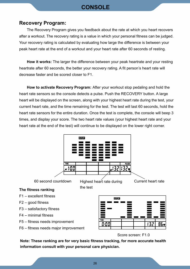
How to activate Recovery Program: After your workout stop pedaling and hold the
heart rate sensors so the console detects a pulse. Push the RECOVERY button. A large
heart will be displayed on the screen, along with your highest heart rate during the test, your
current heart rate, and the time remaining for the test. The test will last 60 seconds, hold the
heart rate sensors for the entire duration. Once the test is complete, the console will beep 3
times, and display your score. The two heart rate values (your highest heart rate and your
heart rate at the end of the test) will continue to be displayed on the lower right corner.
The fitness ranking
F1 – excellent fitness
F2 – good fitness
F3 – satisfactory fitness
F4 – minimal fitness
F5 – fitness needs improvement
F6 – fitness needs major improvement
Score screen: F1.0
Highest heart rate during
the test
Current heart rate 60 second countdown
Note: These ranking are for very basic fitness tracking, for more accurate health
information consult with your personal care physician.
27
ADJUSTMENTS
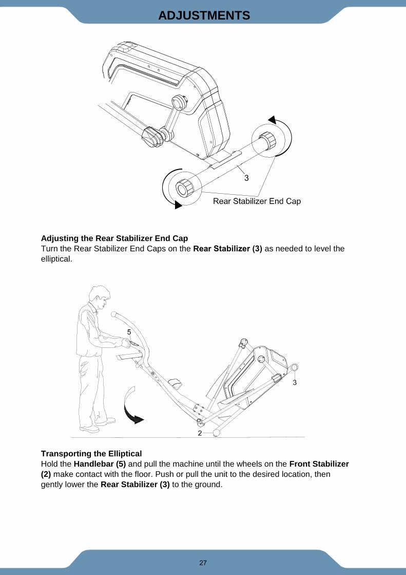
Adjusting the Rear Stabilizer End Cap
Turn the Rear Stabilizer End Caps on the Rear Stabilizer (3) as needed to level the
elliptical.
Transporting the Elliptical
Hold the Handlebar (5) and pull the machine until the wheels on the Front Stabilizer
(2) make contact with the floor. Push or pull the unit to the desired location, then
gently lower the Rear Stabilizer (3) to the ground.
3
28
TROUBLESHOOTING & MAINTENANCE
TROUBLE SHOOTING
PROBLEM: The elliptical wobbles when in use.
SOLUTION: Turn the rear stabilizer end cap on the rear stabilizer as needed to
level the elliptical.
PROBLEM: There is no display on the console.
SOLUTION: Remove the console and verify the wires that come from the
console are properly connected to the wires that come from the front post.
PROBLEM: There is no heart rate reading or there is erratic / inconsistent
reading.
SOLUTION: Make sure that the wire connections for the hand pulse sensors are
secure.
SOLUTION: To ensure the pulse readout is more precise, always hold on to the
handlebar grip sensors with two hands instead of just with one hand.
SOLUTION: Avoid gripping the hand pulse sensors too tight. Try to maintain
moderate pressure while holding onto the hand pulse sensors.
PROBLEM: The elliptical makes a squeaking noise when in use.
SOLUTION: The bolts may be loose on the elliptical. Please inspect all of the
bolts and tighten any loose bolts.
Problem Potential Cause Correction
E1 1. The motor does not
activate
1) Motor Problems
Symptoms include an unusually loud noise
coming from the Motor, which means the
Gears are NOT meshing correctly. Try
reversing the resistance and try again. If
this fails then contact customer service.
Problem Potential Cause Correction
E2 1. There is something
wrong with cables.
Check if the cables are damaged
2. There is something
wrong with console.
Change the console. contact customer
service
3. There is something
wrong with motor.
Change the motor. contact customer
service
29
TROUBLESHOOTING & MAINTENANCE
MAINTENANCE
Cleaning
The unit can be cleaned with a soft cloth and mild detergent. Do not use abrasives or
solvents on plastic parts. Wipe your sweat off the unit after each use. Be careful not to
get excessive moisture on the console display panel, as this might cause an electrical
hazard or cause the electronics to fail. Keep the unit and the console out of direct
sunlight to prevent screen damage or premature wear. Inspect all assembly bolts and
pedals on the machine for proper tightness every week.
Storage
Store the unit in a clean and dry environment away from pets and children.
.
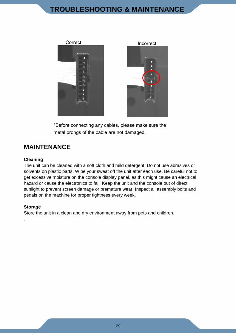
Correct Incorrect
*Before connecting any cables, please make sure the
metal prongs of the cable are not damaged.
30
WARRANTY
MANUFACTURER’S LIMITED WARRANTY
Paradigm Health & Wellness warrants to the original purchaser that this product is free from
defects in material and workmanship when used for the purpose intended, under the
conditions that it has been installed and operated in accordance with Paradigm’s Owner’s
Manual. Paradigm’s obligation under this warranty applies to the following:
COMPONENT LENGTH OF WARRANTY
Structural Frame 1 year For Home Use Only
All Other Components 90 days For Home Use Only
(computer display, electronics, upholstery, foam, ball bearings, pulleys, belts, cables, wires,
shocks, covers, tension, internal mechanism, wheels, pedals, knobs, accessories and
hardware)
Exclusions from Warranty Coverage:
Paradigm does not warrant against and is not responsible for, and no implied warranty shall be deemed to cover, any
product failure, product malfunction, or damages attributable to:
1. Improper installation and/or failure to abide by Paradigm’s installation guidelines;
2. Use of this product beyond normal home use, or in an application for which it was not designed;
3. Cosmetic items such as scratches, dents or discolorations;
4. Damage caused by normal wear and tear, vandalism, accidental or by animals;
5. Any act of Nature (such as fire, flooding, snow, ice, hurricane, earthquake, lightning or other natural disaster),
environmental condition (such as air pollution, mold, mildew, etc.), or staining from foreign substances (such as dirt,
grease, oil, etc.);
6. Normal weathering due to exposure to sunlight, weather and atmosphere which can cause colored surfaces to,
among other things, flake, chalk, or accumulate dirt or stains; or
7. Improper operation, alteration, handling, storage, abuse or neglect of the products.
Paradigm, using its sole discretion, will either repair or replace free of charge any part(s) proven to
be defective under normal home use. Any repair or replacement shall provide no new warranty
coverage, but shall retain only the remaining portion of the original product’s warranty. This
warranty is offered only to the original purchaser and is not transferable. Proof of original purchase
is required.
Ordering Replacement Parts
Replacement parts can be ordered by emailing our customer service department:
Open Daily 8:00 AM - 5:00 PM (PST).
When ordering replacement parts please have the following information ready:
1. Owner’s Manual
2. Model Number
3. Description of Parts
4. Part Number
5. Date of Purchase
31
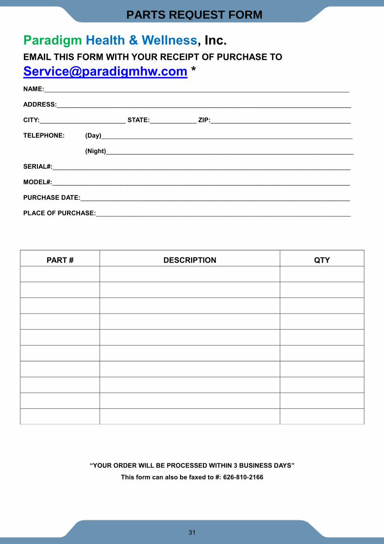
PARTS REQUEST FORM
Paradigm Health & Wellness, Inc.
EMAIL THIS FORM WITH YOUR RECEIPT OF PURCHASE TO
NAME:_____________________________________________________________________________________
ADDRESS:__________________________________________________________________________________
CITY:________________________ STATE:_____________ ZIP:_______________________________________
TELEPHONE: (Day)______________________________________________________________________
(Night)_____________________________________________________________________
SERIAL#:___________________________________________________________________________________
MODEL#:___________________________________________________________________________________
PURCHASE DATE:___________________________________________________________________________
PLACE OF PURCHASE:_______________________________________________________________________
“YOUR ORDER WILL BE PROCESSED WITHIN 3 BUSINESS DAYS”
This form can also be faxed to #: 626-810-2166
PART # DESCRIPTION QTY