Embed Size (px)
Citation preview
Piezoelectric material-based energy harvesting devices: advances of SSH optimization techniques (1999-2009) 165
Piezoelectric material-based energy harvesting devices: advances of SSH optimization techniques (1999-2009)
Elie Lefeuvre, Mickaël Lallart, Claude Richard and Daniel Guyomar
X
Piezoelectric material-based energy harvesting devices: advances of SSH optimization
techniques (1999-2009)
Elie Lefeuvre1, Mickaël Lallart2, Claude Richard2 and Daniel Guyomar2
1Univ. Paris-Sud 2INSA de Lyon
France
1. Introduction
Energy harvesting, also known as power harvesting or energy scavenging, consists in using ambient energy to power small electronic or electrical devices. That includes thermoelectrics, piezoelectrics and electrodynamics, among other options, which begin now to be used in a growing variety of applications. This chapter focuses on piezoelectrics, whose use for the purpose of generating electricity is actually not a recent idea (McLean Nicolson A., 1931). Piezoelectric materials have high power densities, but setting up large amount of these materials for high power applications is technically difficult. Consequently, they cannot compete with electromagnetic devices for most of usual applications of electrical energy production. Nonetheless, piezoelectric materials have recently encountered renewed interest for miniaturized energy harvesting devices from ambient vibrations. Drastic increase of international research efforts has been observed since last ten years in this field (Anton et al., 2007), and commercial products are becoming available (Energy Harvesting Forum (Online)). Such energy harvesting devices aim at replacing batteries in very low power electronic devices such as wireless sensors networks and control systems. Their use for recharging batteries of mobile electronic devices is also under development (Krikke, 2005). Maintenance free, self-powered devices for their lifetime has become an industrial objective for the next few years. However, there are further mountains to climb from self-powered devices become commonplace. A deepened analysis of the papers published during last decade in the field of piezoelectric energy harvesting reveals that significant part of the works focused on mechanical optimization without taking into account constraints of the electrical side of the problem. Contrariwise, another part of these works has studied optimization from the electrical point of view without taking into account the effects reciprocally induced on the mechanical side. As a result, the solutions proposed were often non-optimal and sometimes very far from concerns of practical applications. Effective applications of piezoelectric energy harvesting concept actually require overall analysis of the problem (Mitcheson et al, 2007; Lefeuvre et
9
www.intechopen.com
Piezoelectric Ceramics166
al, 2009). To highlight all the aspects of this multi-physics optimization problem, this chapter exposes first the different energy conversions involved from ambient vibrations to usable electricity. The effects of couplings which link each stage of the energy conversion process are clearly identified. Based on generic single degree of freedom model of the electromechanical part, effective methods for analyzing power output and energy conversion cycles of piezoelectric energy harvesting devices have been presented (Guyomar et al, 2005; Shu et al, 2006). Such analysis show in particular the importance of properly processing the current and the voltage delivered by the piezoelectric material for enabling effective energy conversion process. This side of the power optimization problem has been broadly investigated by the authors of this chapter. They have in particular proposed novel techniques which greatly improve energy transfers compared to conventional techniques (Lefeuvre et al, 2004). The so-called SSH techniques (SSH stands for “Synchronized Switching for Harvesting”) were derived from piezoelectric semi-passive techniques formerly developed by Richard et al. (Richard et al., 1999) for vibration damping. Parallel-SSHI and Series-SSHI were the first techniques proposed by the authors for the purpose of energy harvesting. Then, other techniques such as SECE and DSSH were developed (Lefeuvre et al, 2006a; Lallart et al, 2008c). Practical interest of these techniques has been demonstrated through several prototypes, with important efforts for lowering consumption of electronic circuitry needed for implementation (Lefeuvre et al, 2006b; Lallart et al, 2008b). Perspectives of Microsystems applications has motivated developments specifically dedicated to very-low piezoelectric voltages (Makiara et al, 2006; Lallart et al, 2008a; Garbuio et al, 2009). This chapter presents the evolution of the synchronized switching approach, from the original techniques to the last advances in this domain. The different techniques are compared in term of theoretical performances, and practical implementation issues are discussed. Finally, future trends, challenges and development perspectives for piezoelectric energy harvesting are outlined in the conclusion of this chapter. 2. Energy conversion steps
Take into account of each step of the energy conversion chain appear essential for effective optimization of energy harvesting devices. For this purpose, accurate analysis and modelling of mechanical and electrical interactions related to energy conversions which occur at each stage of the system are required. General diagram of mechanical-to-electrical energy conversion through piezoelectric effect is depicted in Fig. 1. Input mechanical energy may have various origins, such as shocks or vibrations, with various frequency spectrums. This mechanical energy is transmitted to the piezoelectric material through an important element of the device, so called “mechanical structure”, which may act as a band-pass filter (in steady state operation), but also as intermediate mechanical energy storage tank (in impulse mode of operation). Variations of the strain/stress of the piezoelectric material enable conversion from mechanical to electrical energy: an alternating electric charge is generated on the piezoelectric electrodes by converse effect.
It must be noted that resulting AC piezoelectric voltage and current are neither suitable for energy storage devices nor for small electronic or electrical devices. These devices actually require DC voltage. So, another element must be included in the energy conversion chain: the so called “electrical interface”, whose basic function is AC to DC conversion of electrical energy. In addition, this electrical interface may ensure the function of output voltage regulation. But the most profitable effect which may be induced by this last interface is overall optimization and improvement of the electromechanical energy conversion.
Input Mechanical
Energy
(shock or vibration)
Output Electrical Energy
(DC)
Mechanical structure
Piezoelectric Material
Electrical Interface
Electrical Energy
(AC)
Variable strain/stress
Fig. 1. General energy conversion diagram of piezoelectric energy harvesting devices. Optimization of the energy conversion process based on the principle of impedance matching has been proposed by Ottman et al. (Ottman et al., 2002). This principle is actually a well known method for determining the impedance of the electric load which maximizes the power of an electrical generator knowing its internal impedance. Indeed, electromechanical structure of the energy harvesting devices can be considered as equivalent to an electrical circuit composed of an electrical current generator connected to an “internal” impedance network. Since actual electric load usually don’t behave like the desired “optimal load”, emulation of the optimal load impedance can be achieved using DC-DC switching mode electronic power converters included in the “Electrical Interface” block. Several energy-efficient solutions designed for the purpose of emulation of the ideal load impedance have been proposed (Ottman et al, 2003; Roundy et al, 2004; Lefeuvre et al, 2006b). The SSH optimization techniques, which are based on fundamentally different approach, are also part of the “Electrical Interface” block.
3. Electromechanical modelling
Large diversity of mechanical structures associated to various piezoelectric materials has been investigated for energy harvesting. Most common ones are cantilever and diaphragm, such as depicted on Fig. 2. These structures are mechanically excited by ambient vibrations which creates the base motion. Forces induced by inertial effect and stiffness of the structure thus result in strain/stress variations of the piezoelectric material. Such vibrating electromechanical devices can be modelled as single degree of freedom mass+spring+damper+piezo coupling near a resonance frequency, as shown on Fig. 3 (Richards et al., 2004; Guyomar et al., 2005; Badel et al., 2007). In this approach, an effective mass M is bounded on a spring of effective stiffness KE, on a damper of viscous coefficient C and on a piezoelectric element characterized by effective coefficient and capacitance C0. These effective coefficients depend on materials physical characteristics and on design of energy harvesters. They may be derived using modal analysis (Wang et al., 1999; Badel et al., 2007).
www.intechopen.com

Piezoelectric material-based energy harvesting devices: advances of SSH optimization techniques (1999-2009) 167
al, 2009). To highlight all the aspects of this multi-physics optimization problem, this chapter exposes first the different energy conversions involved from ambient vibrations to usable electricity. The effects of couplings which link each stage of the energy conversion process are clearly identified. Based on generic single degree of freedom model of the electromechanical part, effective methods for analyzing power output and energy conversion cycles of piezoelectric energy harvesting devices have been presented (Guyomar et al, 2005; Shu et al, 2006). Such analysis show in particular the importance of properly processing the current and the voltage delivered by the piezoelectric material for enabling effective energy conversion process. This side of the power optimization problem has been broadly investigated by the authors of this chapter. They have in particular proposed novel techniques which greatly improve energy transfers compared to conventional techniques (Lefeuvre et al, 2004). The so-called SSH techniques (SSH stands for “Synchronized Switching for Harvesting”) were derived from piezoelectric semi-passive techniques formerly developed by Richard et al. (Richard et al., 1999) for vibration damping. Parallel-SSHI and Series-SSHI were the first techniques proposed by the authors for the purpose of energy harvesting. Then, other techniques such as SECE and DSSH were developed (Lefeuvre et al, 2006a; Lallart et al, 2008c). Practical interest of these techniques has been demonstrated through several prototypes, with important efforts for lowering consumption of electronic circuitry needed for implementation (Lefeuvre et al, 2006b; Lallart et al, 2008b). Perspectives of Microsystems applications has motivated developments specifically dedicated to very-low piezoelectric voltages (Makiara et al, 2006; Lallart et al, 2008a; Garbuio et al, 2009). This chapter presents the evolution of the synchronized switching approach, from the original techniques to the last advances in this domain. The different techniques are compared in term of theoretical performances, and practical implementation issues are discussed. Finally, future trends, challenges and development perspectives for piezoelectric energy harvesting are outlined in the conclusion of this chapter. 2. Energy conversion steps
Take into account of each step of the energy conversion chain appear essential for effective optimization of energy harvesting devices. For this purpose, accurate analysis and modelling of mechanical and electrical interactions related to energy conversions which occur at each stage of the system are required. General diagram of mechanical-to-electrical energy conversion through piezoelectric effect is depicted in Fig. 1. Input mechanical energy may have various origins, such as shocks or vibrations, with various frequency spectrums. This mechanical energy is transmitted to the piezoelectric material through an important element of the device, so called “mechanical structure”, which may act as a band-pass filter (in steady state operation), but also as intermediate mechanical energy storage tank (in impulse mode of operation). Variations of the strain/stress of the piezoelectric material enable conversion from mechanical to electrical energy: an alternating electric charge is generated on the piezoelectric electrodes by converse effect.
It must be noted that resulting AC piezoelectric voltage and current are neither suitable for energy storage devices nor for small electronic or electrical devices. These devices actually require DC voltage. So, another element must be included in the energy conversion chain: the so called “electrical interface”, whose basic function is AC to DC conversion of electrical energy. In addition, this electrical interface may ensure the function of output voltage regulation. But the most profitable effect which may be induced by this last interface is overall optimization and improvement of the electromechanical energy conversion.
Input Mechanical
Energy
(shock or vibration)
Output Electrical Energy
(DC)
Mechanical structure
Piezoelectric Material
Electrical Interface
Electrical Energy
(AC)
Variable strain/stress
Fig. 1. General energy conversion diagram of piezoelectric energy harvesting devices. Optimization of the energy conversion process based on the principle of impedance matching has been proposed by Ottman et al. (Ottman et al., 2002). This principle is actually a well known method for determining the impedance of the electric load which maximizes the power of an electrical generator knowing its internal impedance. Indeed, electromechanical structure of the energy harvesting devices can be considered as equivalent to an electrical circuit composed of an electrical current generator connected to an “internal” impedance network. Since actual electric load usually don’t behave like the desired “optimal load”, emulation of the optimal load impedance can be achieved using DC-DC switching mode electronic power converters included in the “Electrical Interface” block. Several energy-efficient solutions designed for the purpose of emulation of the ideal load impedance have been proposed (Ottman et al, 2003; Roundy et al, 2004; Lefeuvre et al, 2006b). The SSH optimization techniques, which are based on fundamentally different approach, are also part of the “Electrical Interface” block.
3. Electromechanical modelling
Large diversity of mechanical structures associated to various piezoelectric materials has been investigated for energy harvesting. Most common ones are cantilever and diaphragm, such as depicted on Fig. 2. These structures are mechanically excited by ambient vibrations which creates the base motion. Forces induced by inertial effect and stiffness of the structure thus result in strain/stress variations of the piezoelectric material. Such vibrating electromechanical devices can be modelled as single degree of freedom mass+spring+damper+piezo coupling near a resonance frequency, as shown on Fig. 3 (Richards et al., 2004; Guyomar et al., 2005; Badel et al., 2007). In this approach, an effective mass M is bounded on a spring of effective stiffness KE, on a damper of viscous coefficient C and on a piezoelectric element characterized by effective coefficient and capacitance C0. These effective coefficients depend on materials physical characteristics and on design of energy harvesters. They may be derived using modal analysis (Wang et al., 1999; Badel et al., 2007).
www.intechopen.com

Piezoelectric Ceramics168
Seismic Mass
Piezo Seismic Mass Piezo
Base Base
Fig. 2. Cantilever and diaphragm electromechanical structures for energy harvesting. Dynamic equation of the electromechanical structure is given by (1), where the effective mechanical displacement u is the difference of the seismic mass displacement u2 and the generator’s base displacement u1. This equation shows in particular the action of the inertial force on the system, which is the product of the effective mass M and the base mechanical acceleration 1u . The effective piezoelectric coefficient defines the relation of the effective piezoelectric force FP and the piezoelectric voltage V. This coefficient also defines the relation of the piezoelectric internal current I with the mechanical speed u , as written in (2).
1uMFuKuCuM P (1)
uIVFP
(2)
Owing to its simplicity, such an analytical model of the electromechanical part is very convenient for energy conversion analysis. This is actually the simplest way for taking into account all the electromechanical interactions.
I
C0
Electrical Circuit
Fp
Dynamic Mass M
KE C
Piezoelectric element
Galilean reference
u1
u2
Base
V
Fig. 3. Single degree of freedom electromechanical model.
4. Standard AC-DC interface
The electrical energy generated by the electromechanical part of the energy harvester, whose modeling was presented in the previous section, is transmitted here to the circuit represented on Fig. 4 (a). The typical application considered here is the recharging of an electrochemical battery. The battery needs stabilized DC voltage while the vibrating piezoelectric element generates an AC voltage (Fig. 4 (b)). So, the electrical interface connected between the piezoelectric element and the battery must ensure electrical compatibility. The so called “standard” interface is the simplest way to achieve this function: the piezoelectric voltage is first rectified by the diode bridge, and then the controller (DC-DC Converter) ensures the power optimization and voltage regulation.
Piezoelectric element
I
C0
Vr DC-DC
Converter Vbat
+
-
V
+
-
(a) (b)
u(t)
Vrect
t
V(t) t
-Vrect
+
-
Fig. 4. (a) Standard electrical interface. (b) Typical waveforms of displacement and voltages.
4.1 Steady-state analysis The model equations (1) and (2) are solved at the resonance frequency of the single-mode resonator. The base excitation of the energy harvester is considered here with sinusoidal displacement u1 of magnitude U1 and angular frequency (3). As shown on Fig. 4 (b), nonlinearities are induced by the electrical circuit on the piezoelectric voltage V. In spite of this, the displacement u of the electromechanical part is assumed to be sinusoidal. Indeed, effective electromechanical coupling is generally not important enough in practice to observe the impact of the voltage nonlinearities on the displacement. tUu sin11 (3) For the sake of simplifying the analysis, the DC part of the electric load composed of the DC-DC converter and the electrochemical battery (Fig. 4 (a)) is modeled in the following developments by an equivalent resistor R which consumes same power as the actual load:
RVP r /2 . Losses due to the voltage drop across the diodes of the rectifier are neglected. Electrical equations of this circuit (Ottman et al., 2001; Lefeuvre et al., 2006b) and equations (1) (2) (3) lead to the following expression (4) of the power P supplied by the energy harvester at the resonance angular frequency r (Guyomar et al. 2005, Lefeuvre et al. 2006a):
220
2
21
42
20
2
2//22/
r
r
r RCRC
UMRC
RP (4)
www.intechopen.com

Piezoelectric material-based energy harvesting devices: advances of SSH optimization techniques (1999-2009) 169
Seismic Mass
Piezo Seismic Mass Piezo
Base Base
Fig. 2. Cantilever and diaphragm electromechanical structures for energy harvesting. Dynamic equation of the electromechanical structure is given by (1), where the effective mechanical displacement u is the difference of the seismic mass displacement u2 and the generator’s base displacement u1. This equation shows in particular the action of the inertial force on the system, which is the product of the effective mass M and the base mechanical acceleration 1u . The effective piezoelectric coefficient defines the relation of the effective piezoelectric force FP and the piezoelectric voltage V. This coefficient also defines the relation of the piezoelectric internal current I with the mechanical speed u , as written in (2).
1uMFuKuCuM P (1)
uIVFP
(2)
Owing to its simplicity, such an analytical model of the electromechanical part is very convenient for energy conversion analysis. This is actually the simplest way for taking into account all the electromechanical interactions.
I
C0
Electrical Circuit
Fp
Dynamic Mass M
KE C
Piezoelectric element
Galilean reference
u1
u2
Base
V
Fig. 3. Single degree of freedom electromechanical model.
4. Standard AC-DC interface
The electrical energy generated by the electromechanical part of the energy harvester, whose modeling was presented in the previous section, is transmitted here to the circuit represented on Fig. 4 (a). The typical application considered here is the recharging of an electrochemical battery. The battery needs stabilized DC voltage while the vibrating piezoelectric element generates an AC voltage (Fig. 4 (b)). So, the electrical interface connected between the piezoelectric element and the battery must ensure electrical compatibility. The so called “standard” interface is the simplest way to achieve this function: the piezoelectric voltage is first rectified by the diode bridge, and then the controller (DC-DC Converter) ensures the power optimization and voltage regulation.
Piezoelectric element
I
C0
Vr DC-DC
Converter Vbat
+
-
V
+
-
(a) (b)
u(t)
Vrect
t
V(t) t
-Vrect
+
-
Fig. 4. (a) Standard electrical interface. (b) Typical waveforms of displacement and voltages.
4.1 Steady-state analysis The model equations (1) and (2) are solved at the resonance frequency of the single-mode resonator. The base excitation of the energy harvester is considered here with sinusoidal displacement u1 of magnitude U1 and angular frequency (3). As shown on Fig. 4 (b), nonlinearities are induced by the electrical circuit on the piezoelectric voltage V. In spite of this, the displacement u of the electromechanical part is assumed to be sinusoidal. Indeed, effective electromechanical coupling is generally not important enough in practice to observe the impact of the voltage nonlinearities on the displacement. tUu sin11 (3) For the sake of simplifying the analysis, the DC part of the electric load composed of the DC-DC converter and the electrochemical battery (Fig. 4 (a)) is modeled in the following developments by an equivalent resistor R which consumes same power as the actual load:
RVP r /2 . Losses due to the voltage drop across the diodes of the rectifier are neglected. Electrical equations of this circuit (Ottman et al., 2001; Lefeuvre et al., 2006b) and equations (1) (2) (3) lead to the following expression (4) of the power P supplied by the energy harvester at the resonance angular frequency r (Guyomar et al. 2005, Lefeuvre et al. 2006a):
220
2
21
42
20
2
2//22/
r
r
r RCRC
UMRC
RP (4)
www.intechopen.com

Piezoelectric Ceramics170
One or two different values can be found for the optimal load resistance which maximizes the power, depending on the electromechanical figure of merit of the electromechanical part. This figure of merit is defined as the product of the global coupling k squared and the electromechanical quality factor QM:
0
22
CCQk
rM
(5)
For weak values of the electromechanical figure of merit, MQk 2 , only one optimal value Ropt of the load equivalent resistance maximizes the power. Expressions of Ropt and the corresponding maximal power are the following:
CUM
Qk
QkP
CR
r
M
M
ropt
21
42
22
2
max
0
2
2
(6)
For higher values of the electromechanical figure of merit, MQk 2 , two different optimal value Ropt of the load equivalent resistance maximizes the power. In this case, expressions of Ropt and the corresponding maximal power become:
CUMP
CC
CCCCR
rlim
r
ropt
8
2
22
21
42
20
02
0
(7)
Thus, according to these results, maximization of the power generated by the energy harvester can be summarized as choosing an optimal value for the load equivalent resistance R. The value of this resistor is determined by the electromechanical characteristics of the system and by the excitation frequency.
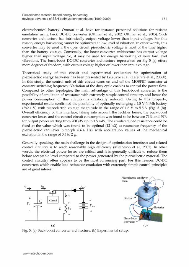
4.2 Resistor emulation using DC-DC converters DC-DC switching mode power converters technology is well known for its high efficiency, which typically reach 80% to 99%. They enable accurate dynamic control of their power flow through their active power switches and dedicated regulation circuitry. Thus, such DC-DC converter technology appears ideal for efficient emulation of the optimal load resistor, while transferring most of the harvested energy to the actual load. Control strategy and related regulation circuitry must be designed in such a way that the input voltage and the input current of the converter vary proportionally. Such function is, by principle, achievable with any switching mode converter topology, but with some input and output voltage limitations. In the context of our application, the input voltage range is directly related to the considered level of vibration, while output voltage range is determined by the characteristics of the
electrochemical battery. Ottman et al. have for instance presented solutions for resistor emulation using buck DC-DC converter (Ottman et al., 2002; Ottman et al., 2003). Such converter architecture has intrinsically output voltage lower than input voltage. For this reason, energy harvesting cannot be optimized at low level of vibration. In other words, this converter may be used if the open circuit piezoelectric voltage is most of the time higher than the battery voltage. Conversely, the boost converter architecture has output voltage higher than input voltage. So, it may be used for energy harvesting of very low level vibrations. The buck-boost DC-DC converter architecture represented on Fig 5 (a) offers more degrees of freedom, with output voltage higher or lower than input voltage. Theoretical study of this circuit and experimental evaluation for optimization of piezoelectric energy harvester has been presented by Lefeuvre et al. (Lefeuvre et al., 2006b). In this study, the control unit of this circuit turns on and off the MOSFET transistor at constant switching frequency. Variation of the duty cycle enables to control the power flow. Compared to other topologies, the main advantage of this buck-boost converter is the possibility of emulation of resistance with extremely simple control circuitry, and hence the power consumption of this circuitry is drastically reduced. Owing to this property, experimental results confirmed the possibility of optimally recharging a 4.8 V NiMh battery (2x2.4 V) with piezoelectric voltage magnitude in the range of 1.6 V to 5.5 V (Fig. 5 (b)). Overall efficiency of this interface, taking into account the rectifier losses, the buck-boost converter losses and the control circuit consumption was found to be between 71% and 79% for output power starting from 200 µW up to 1.5 mW. The emulated load resistance could be fixed at the value which was found to be optimal (12 k) at resonance frequency of the piezoelectric cantilever bimorph (66.4 Hz) with acceleration values of the mechanical excitation in the range of 0.5 to 2 g. Generally speaking, the main challenge in the design of optimization interfaces and related control circuitry is to reach reasonably high efficiency (Mitcheson et al., 2007). In other words, the electrical power losses are critical and it is generally difficult to reduce them below acceptable level compared to the power generated by the piezoelectric material. The control circuitry often appears to be the most consuming part. For this reason, DC-DC converters which enable load resistance emulation with extremely simple control principles are of great interest.
L
iL
ibat
Cr Vr
+
-
Vbat
-
+
Control
ir iM
VL
+
-
(a) (b)
Piezoelectric cantilever beam
Buck-boost converter
Batteries
Shaker
Fig. 5. (a) Buck-boost converter architecture. (b) Experimental setup.
www.intechopen.com
Piezoelectric material-based energy harvesting devices: advances of SSH optimization techniques (1999-2009) 171
One or two different values can be found for the optimal load resistance which maximizes the power, depending on the electromechanical figure of merit of the electromechanical part. This figure of merit is defined as the product of the global coupling k squared and the electromechanical quality factor QM:
0
22
CCQk
rM
(5)
For weak values of the electromechanical figure of merit, MQk 2 , only one optimal value Ropt of the load equivalent resistance maximizes the power. Expressions of Ropt and the corresponding maximal power are the following:
CUM
Qk
QkP
CR
r
M
M
ropt
21
42
22
2
max
0
2
2
(6)
For higher values of the electromechanical figure of merit, MQk 2 , two different optimal value Ropt of the load equivalent resistance maximizes the power. In this case, expressions of Ropt and the corresponding maximal power become:
CUMP
CC
CCCCR
rlim
r
ropt
8
2
22
21
42
20
02
0
(7)
Thus, according to these results, maximization of the power generated by the energy harvester can be summarized as choosing an optimal value for the load equivalent resistance R. The value of this resistor is determined by the electromechanical characteristics of the system and by the excitation frequency.
4.2 Resistor emulation using DC-DC converters DC-DC switching mode power converters technology is well known for its high efficiency, which typically reach 80% to 99%. They enable accurate dynamic control of their power flow through their active power switches and dedicated regulation circuitry. Thus, such DC-DC converter technology appears ideal for efficient emulation of the optimal load resistor, while transferring most of the harvested energy to the actual load. Control strategy and related regulation circuitry must be designed in such a way that the input voltage and the input current of the converter vary proportionally. Such function is, by principle, achievable with any switching mode converter topology, but with some input and output voltage limitations. In the context of our application, the input voltage range is directly related to the considered level of vibration, while output voltage range is determined by the characteristics of the
electrochemical battery. Ottman et al. have for instance presented solutions for resistor emulation using buck DC-DC converter (Ottman et al., 2002; Ottman et al., 2003). Such converter architecture has intrinsically output voltage lower than input voltage. For this reason, energy harvesting cannot be optimized at low level of vibration. In other words, this converter may be used if the open circuit piezoelectric voltage is most of the time higher than the battery voltage. Conversely, the boost converter architecture has output voltage higher than input voltage. So, it may be used for energy harvesting of very low level vibrations. The buck-boost DC-DC converter architecture represented on Fig 5 (a) offers more degrees of freedom, with output voltage higher or lower than input voltage. Theoretical study of this circuit and experimental evaluation for optimization of piezoelectric energy harvester has been presented by Lefeuvre et al. (Lefeuvre et al., 2006b). In this study, the control unit of this circuit turns on and off the MOSFET transistor at constant switching frequency. Variation of the duty cycle enables to control the power flow. Compared to other topologies, the main advantage of this buck-boost converter is the possibility of emulation of resistance with extremely simple control circuitry, and hence the power consumption of this circuitry is drastically reduced. Owing to this property, experimental results confirmed the possibility of optimally recharging a 4.8 V NiMh battery (2x2.4 V) with piezoelectric voltage magnitude in the range of 1.6 V to 5.5 V (Fig. 5 (b)). Overall efficiency of this interface, taking into account the rectifier losses, the buck-boost converter losses and the control circuit consumption was found to be between 71% and 79% for output power starting from 200 µW up to 1.5 mW. The emulated load resistance could be fixed at the value which was found to be optimal (12 k) at resonance frequency of the piezoelectric cantilever bimorph (66.4 Hz) with acceleration values of the mechanical excitation in the range of 0.5 to 2 g. Generally speaking, the main challenge in the design of optimization interfaces and related control circuitry is to reach reasonably high efficiency (Mitcheson et al., 2007). In other words, the electrical power losses are critical and it is generally difficult to reduce them below acceptable level compared to the power generated by the piezoelectric material. The control circuitry often appears to be the most consuming part. For this reason, DC-DC converters which enable load resistance emulation with extremely simple control principles are of great interest.
L
iL
ibat
Cr Vr
+
-
Vbat
-
+
Control
ir iM
VL
+
-
(a) (b)
Piezoelectric cantilever beam
Buck-boost converter
Batteries
Shaker
Fig. 5. (a) Buck-boost converter architecture. (b) Experimental setup.
www.intechopen.com
Piezoelectric Ceramics172
5. The SSH techniques
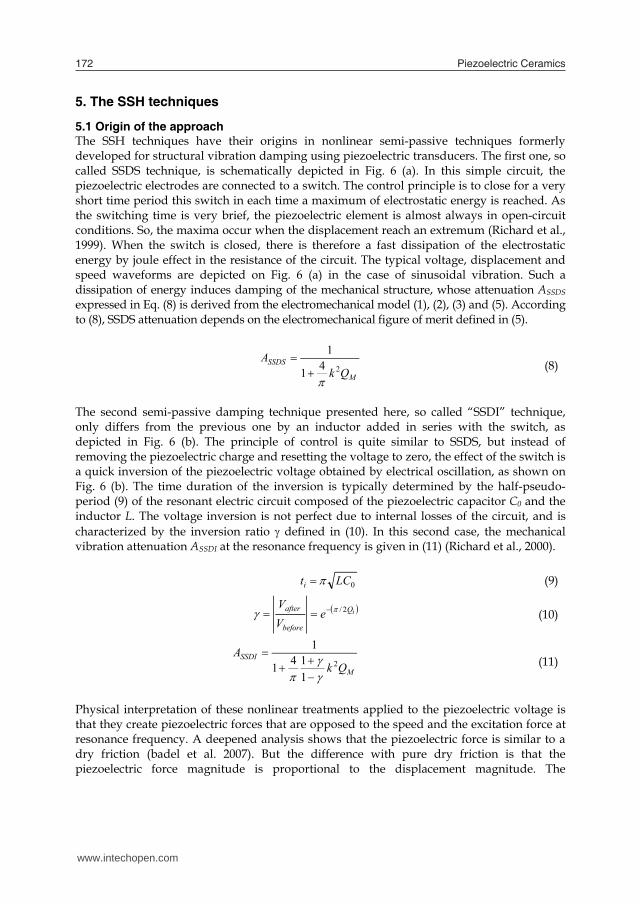
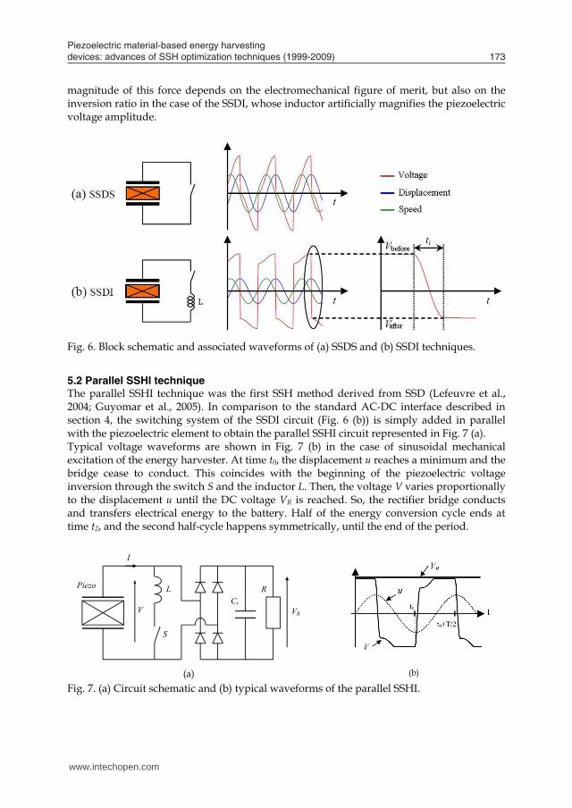
5.1 Origin of the approach The SSH techniques have their origins in nonlinear semi-passive techniques formerly developed for structural vibration damping using piezoelectric transducers. The first one, so called SSDS technique, is schematically depicted in Fig. 6 (a). In this simple circuit, the piezoelectric electrodes are connected to a switch. The control principle is to close for a very short time period this switch in each time a maximum of electrostatic energy is reached. As the switching time is very brief, the piezoelectric element is almost always in open-circuit conditions. So, the maxima occur when the displacement reach an extremum (Richard et al., 1999). When the switch is closed, there is therefore a fast dissipation of the electrostatic energy by joule effect in the resistance of the circuit. The typical voltage, displacement and speed waveforms are depicted on Fig. 6 (a) in the case of sinusoidal vibration. Such a dissipation of energy induces damping of the mechanical structure, whose attenuation ASSDS expressed in Eq. (8) is derived from the electromechanical model (1), (2), (3) and (5). According to (8), SSDS attenuation depends on the electromechanical figure of merit defined in (5).
M
SSDSQk
A241
1
(8)
The second semi-passive damping technique presented here, so called “SSDI” technique, only differs from the previous one by an inductor added in series with the switch, as depicted in Fig. 6 (b). The principle of control is quite similar to SSDS, but instead of removing the piezoelectric charge and resetting the voltage to zero, the effect of the switch is a quick inversion of the piezoelectric voltage obtained by electrical oscillation, as shown on Fig. 6 (b). The time duration of the inversion is typically determined by the half-pseudo-period (9) of the resonant electric circuit composed of the piezoelectric capacitor C0 and the inductor L. The voltage inversion is not perfect due to internal losses of the circuit, and is characterized by the inversion ratio defined in (10). In this second case, the mechanical vibration attenuation ASSDI at the resonance frequency is given in (11) (Richard et al., 2000).
0LCti (9)
iQ
before
after eVV 2/ (10)
M
SSDIQk
A2
1141
1
(11)
Physical interpretation of these nonlinear treatments applied to the piezoelectric voltage is that they create piezoelectric forces that are opposed to the speed and the excitation force at resonance frequency. A deepened analysis shows that the piezoelectric force is similar to a dry friction (badel et al. 2007). But the difference with pure dry friction is that the piezoelectric force magnitude is proportional to the displacement magnitude. The
magnitude of this force depends on the electromechanical figure of merit, but also on the inversion ratio in the case of the SSDI, whose inductor artificially magnifies the piezoelectric voltage amplitude.
Fig. 6. Block schematic and associated waveforms of (a) SSDS and (b) SSDI techniques.
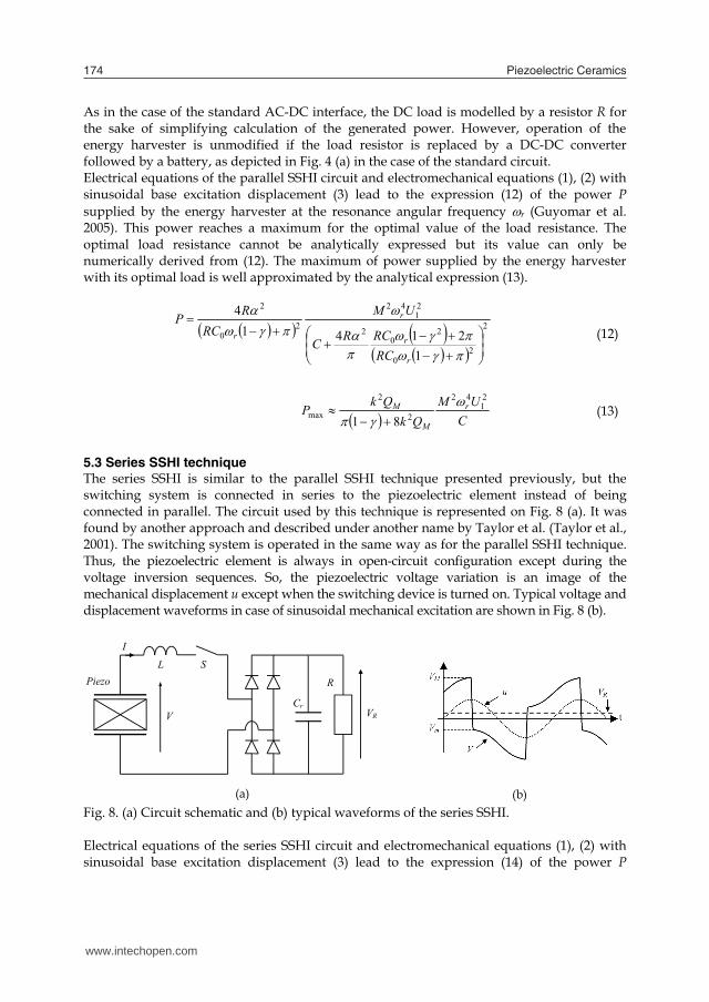
5.2 Parallel SSHI technique The parallel SSHI technique was the first SSH method derived from SSD (Lefeuvre et al., 2004; Guyomar et al., 2005). In comparison to the standard AC-DC interface described in section 4, the switching system of the SSDI circuit (Fig. 6 (b)) is simply added in parallel with the piezoelectric element to obtain the parallel SSHI circuit represented in Fig. 7 (a). Typical voltage waveforms are shown in Fig. 7 (b) in the case of sinusoidal mechanical excitation of the energy harvester. At time t0, the displacement u reaches a minimum and the bridge cease to conduct. This coincides with the beginning of the piezoelectric voltage inversion through the switch S and the inductor L. Then, the voltage V varies proportionally to the displacement u until the DC voltage VR is reached. So, the rectifier bridge conducts and transfers electrical energy to the battery. Half of the energy conversion cycle ends at time t2, and the second half-cycle happens symmetrically, until the end of the period.
(a) (b)
Piezo
V
S
L
I
VR
Cr
R
Fig. 7. (a) Circuit schematic and (b) typical waveforms of the parallel SSHI.
www.intechopen.com
Piezoelectric material-based energy harvesting devices: advances of SSH optimization techniques (1999-2009) 173
5. The SSH techniques
5.1 Origin of the approach The SSH techniques have their origins in nonlinear semi-passive techniques formerly developed for structural vibration damping using piezoelectric transducers. The first one, so called SSDS technique, is schematically depicted in Fig. 6 (a). In this simple circuit, the piezoelectric electrodes are connected to a switch. The control principle is to close for a very short time period this switch in each time a maximum of electrostatic energy is reached. As the switching time is very brief, the piezoelectric element is almost always in open-circuit conditions. So, the maxima occur when the displacement reach an extremum (Richard et al., 1999). When the switch is closed, there is therefore a fast dissipation of the electrostatic energy by joule effect in the resistance of the circuit. The typical voltage, displacement and speed waveforms are depicted on Fig. 6 (a) in the case of sinusoidal vibration. Such a dissipation of energy induces damping of the mechanical structure, whose attenuation ASSDS expressed in Eq. (8) is derived from the electromechanical model (1), (2), (3) and (5). According to (8), SSDS attenuation depends on the electromechanical figure of merit defined in (5).
M
SSDSQk
A241
1
(8)
The second semi-passive damping technique presented here, so called “SSDI” technique, only differs from the previous one by an inductor added in series with the switch, as depicted in Fig. 6 (b). The principle of control is quite similar to SSDS, but instead of removing the piezoelectric charge and resetting the voltage to zero, the effect of the switch is a quick inversion of the piezoelectric voltage obtained by electrical oscillation, as shown on Fig. 6 (b). The time duration of the inversion is typically determined by the half-pseudo-period (9) of the resonant electric circuit composed of the piezoelectric capacitor C0 and the inductor L. The voltage inversion is not perfect due to internal losses of the circuit, and is characterized by the inversion ratio defined in (10). In this second case, the mechanical vibration attenuation ASSDI at the resonance frequency is given in (11) (Richard et al., 2000).
0LCti (9)
iQ
before
after eVV 2/ (10)
M
SSDIQk
A2
1141
1
(11)
Physical interpretation of these nonlinear treatments applied to the piezoelectric voltage is that they create piezoelectric forces that are opposed to the speed and the excitation force at resonance frequency. A deepened analysis shows that the piezoelectric force is similar to a dry friction (badel et al. 2007). But the difference with pure dry friction is that the piezoelectric force magnitude is proportional to the displacement magnitude. The
magnitude of this force depends on the electromechanical figure of merit, but also on the inversion ratio in the case of the SSDI, whose inductor artificially magnifies the piezoelectric voltage amplitude.
Fig. 6. Block schematic and associated waveforms of (a) SSDS and (b) SSDI techniques.
5.2 Parallel SSHI technique The parallel SSHI technique was the first SSH method derived from SSD (Lefeuvre et al., 2004; Guyomar et al., 2005). In comparison to the standard AC-DC interface described in section 4, the switching system of the SSDI circuit (Fig. 6 (b)) is simply added in parallel with the piezoelectric element to obtain the parallel SSHI circuit represented in Fig. 7 (a). Typical voltage waveforms are shown in Fig. 7 (b) in the case of sinusoidal mechanical excitation of the energy harvester. At time t0, the displacement u reaches a minimum and the bridge cease to conduct. This coincides with the beginning of the piezoelectric voltage inversion through the switch S and the inductor L. Then, the voltage V varies proportionally to the displacement u until the DC voltage VR is reached. So, the rectifier bridge conducts and transfers electrical energy to the battery. Half of the energy conversion cycle ends at time t2, and the second half-cycle happens symmetrically, until the end of the period.
(a) (b)
Piezo
V
S
L
I
VR
Cr
R
Fig. 7. (a) Circuit schematic and (b) typical waveforms of the parallel SSHI.
www.intechopen.com
Piezoelectric Ceramics174
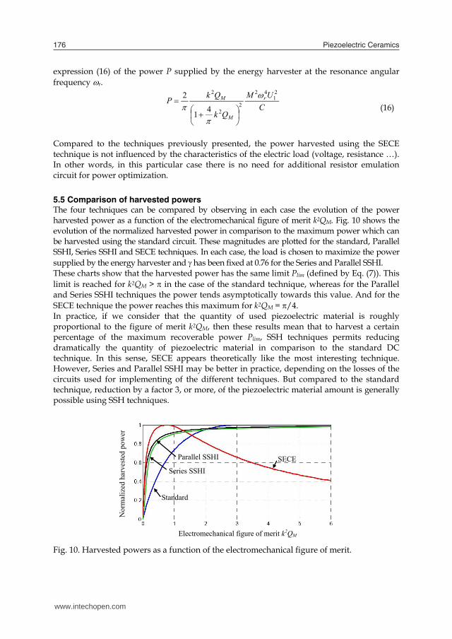
As in the case of the standard AC-DC interface, the DC load is modelled by a resistor R for the sake of simplifying calculation of the generated power. However, operation of the energy harvester is unmodified if the load resistor is replaced by a DC-DC converter followed by a battery, as depicted in Fig. 4 (a) in the case of the standard circuit. Electrical equations of the parallel SSHI circuit and electromechanical equations (1), (2) with sinusoidal base excitation displacement (3) lead to the expression (12) of the power P supplied by the energy harvester at the resonance angular frequency r (Guyomar et al. 2005). This power reaches a maximum for the optimal value of the load resistance. The optimal load resistance cannot be analytically expressed but its value can only be numerically derived from (12). The maximum of power supplied by the energy harvester with its optimal load is well approximated by the analytical expression (13).
2
20
20
2
21
42
20
2
12141
4
r
r
r
r
RCRCRC
UMRC
RP (12)
CUM
QkQkP r
M
M21
42
2
2
max 81
(13)
5.3 Series SSHI technique The series SSHI is similar to the parallel SSHI technique presented previously, but the switching system is connected in series to the piezoelectric element instead of being connected in parallel. The circuit used by this technique is represented on Fig. 8 (a). It was found by another approach and described under another name by Taylor et al. (Taylor et al., 2001). The switching system is operated in the same way as for the parallel SSHI technique. Thus, the piezoelectric element is always in open-circuit configuration except during the voltage inversion sequences. So, the piezoelectric voltage variation is an image of the mechanical displacement u except when the switching device is turned on. Typical voltage and displacement waveforms in case of sinusoidal mechanical excitation are shown in Fig. 8 (b).
(a) (b)
Cr
Piezo
V
S L
VR
R
I
Fig. 8. (a) Circuit schematic and (b) typical waveforms of the series SSHI. Electrical equations of the series SSHI circuit and electromechanical equations (1), (2) with sinusoidal base excitation displacement (3) lead to the expression (14) of the power P
supplied by the energy harvester at the resonance angular frequency r. Equation (15) is an analytical approximation of the maximum power supplied to the optimal load.
2
00
2
21
42
20
22
11214112
14
rr
r
r
RCCC
UMRC
RP (14)
CUM
Qk
QkP r
M
Mmax
21
42
2
2
8112
(15)
5.4 SECE technique The SECE technique basically consists in extracting promptly and entirely the electric energy converted by the piezoelectric element on each extremum of the mechanical displacement u. From the standpoint of the piezoelectric element, the effect is identical to the SSDS technique presented in section 5.1. But instead of being dissipated by Joule effect, this electrical energy is transferred to the load (Lefeuvre et al., 2006a). The circuit used for this technique is composed of a bridge rectifier, a flyback-type switching mode power converter and an electric load (Fig. 9 (a)). The power converter is controlled by the on and off states of the transistor T. When the piezoelectric voltage V reaches an extremum, the transistor is turned on and the electrostatic energy of the piezoelectric element begins to be transferred to the coupled inductor L. When voltage V passes at zero, all the electrostatic energy has been removed from the piezoelectric element and the transistor is turned off. The coupled inductor value is chosen so that duration of the energy extraction sequence is very short compared to the vibration period. Thus, the piezo is on open-circuit configuration most of the time and its voltage is a piecewise function of the mechanical displacement u. Typical voltage and displacement waveforms are depicted in Fig. 9 (b) in case of sinusoidal mechanical excitation.
(a) (b)
Vbat
Fig. 9. (a) Schematic and (b) typical waveforms of SECE. Energy transfer sequences of the SECE circuit and electromechanical equations (1), (2) with sinusoidal base excitation displacement (3) and the figure of merit definition (5) lead to the
www.intechopen.com

Piezoelectric material-based energy harvesting devices: advances of SSH optimization techniques (1999-2009) 175
As in the case of the standard AC-DC interface, the DC load is modelled by a resistor R for the sake of simplifying calculation of the generated power. However, operation of the energy harvester is unmodified if the load resistor is replaced by a DC-DC converter followed by a battery, as depicted in Fig. 4 (a) in the case of the standard circuit. Electrical equations of the parallel SSHI circuit and electromechanical equations (1), (2) with sinusoidal base excitation displacement (3) lead to the expression (12) of the power P supplied by the energy harvester at the resonance angular frequency r (Guyomar et al. 2005). This power reaches a maximum for the optimal value of the load resistance. The optimal load resistance cannot be analytically expressed but its value can only be numerically derived from (12). The maximum of power supplied by the energy harvester with its optimal load is well approximated by the analytical expression (13).
2
20
20
2
21
42
20
2
12141
4
r
r
r
r
RCRCRC
UMRC
RP (12)
CUM
QkQkP r
M
M21
42
2
2
max 81
(13)
5.3 Series SSHI technique The series SSHI is similar to the parallel SSHI technique presented previously, but the switching system is connected in series to the piezoelectric element instead of being connected in parallel. The circuit used by this technique is represented on Fig. 8 (a). It was found by another approach and described under another name by Taylor et al. (Taylor et al., 2001). The switching system is operated in the same way as for the parallel SSHI technique. Thus, the piezoelectric element is always in open-circuit configuration except during the voltage inversion sequences. So, the piezoelectric voltage variation is an image of the mechanical displacement u except when the switching device is turned on. Typical voltage and displacement waveforms in case of sinusoidal mechanical excitation are shown in Fig. 8 (b).
(a) (b)
Cr
Piezo
V
S L
VR
R
I
Fig. 8. (a) Circuit schematic and (b) typical waveforms of the series SSHI. Electrical equations of the series SSHI circuit and electromechanical equations (1), (2) with sinusoidal base excitation displacement (3) lead to the expression (14) of the power P
supplied by the energy harvester at the resonance angular frequency r. Equation (15) is an analytical approximation of the maximum power supplied to the optimal load.
2
00
2
21
42
20
22
11214112
14
rr
r
r
RCCC
UMRC
RP (14)
CUM
Qk
QkP r
M
Mmax
21
42
2
2
8112
(15)
5.4 SECE technique The SECE technique basically consists in extracting promptly and entirely the electric energy converted by the piezoelectric element on each extremum of the mechanical displacement u. From the standpoint of the piezoelectric element, the effect is identical to the SSDS technique presented in section 5.1. But instead of being dissipated by Joule effect, this electrical energy is transferred to the load (Lefeuvre et al., 2006a). The circuit used for this technique is composed of a bridge rectifier, a flyback-type switching mode power converter and an electric load (Fig. 9 (a)). The power converter is controlled by the on and off states of the transistor T. When the piezoelectric voltage V reaches an extremum, the transistor is turned on and the electrostatic energy of the piezoelectric element begins to be transferred to the coupled inductor L. When voltage V passes at zero, all the electrostatic energy has been removed from the piezoelectric element and the transistor is turned off. The coupled inductor value is chosen so that duration of the energy extraction sequence is very short compared to the vibration period. Thus, the piezo is on open-circuit configuration most of the time and its voltage is a piecewise function of the mechanical displacement u. Typical voltage and displacement waveforms are depicted in Fig. 9 (b) in case of sinusoidal mechanical excitation.
(a) (b)
Vbat
Fig. 9. (a) Schematic and (b) typical waveforms of SECE. Energy transfer sequences of the SECE circuit and electromechanical equations (1), (2) with sinusoidal base excitation displacement (3) and the figure of merit definition (5) lead to the
www.intechopen.com
Piezoelectric Ceramics176
expression (16) of the power P supplied by the energy harvester at the resonance angular frequency r.
CUM
Qk
QkP r
M
M21
42
22
2
41
2
(16)
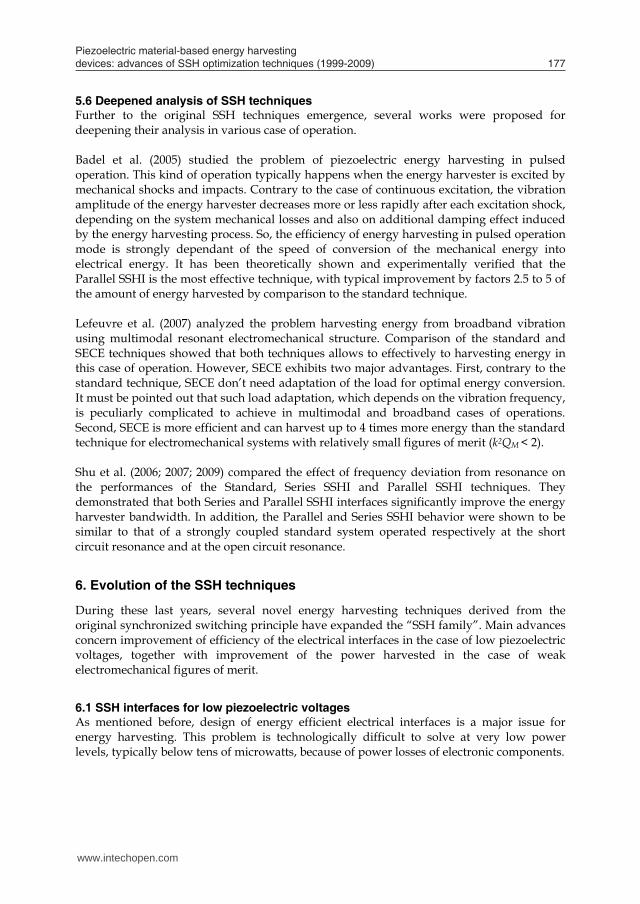
Compared to the techniques previously presented, the power harvested using the SECE technique is not influenced by the characteristics of the electric load (voltage, resistance …). In other words, in this particular case there is no need for additional resistor emulation circuit for power optimization. 5.5 Comparison of harvested powers The four techniques can be compared by observing in each case the evolution of the power harvested power as a function of the electromechanical figure of merit k2QM. Fig. 10 shows the evolution of the normalized harvested power in comparison to the maximum power which can be harvested using the standard circuit. These magnitudes are plotted for the standard, Parallel SSHI, Series SSHI and SECE techniques. In each case, the load is chosen to maximize the power supplied by the energy harvester and has been fixed at 0.76 for the Series and Parallel SSHI. These charts show that the harvested power has the same limit Plim (defined by Eq. (7)). This limit is reached for k2QM > in the case of the standard technique, whereas for the Parallel and Series SSHI techniques the power tends asymptotically towards this value. And for the SECE technique the power reaches this maximum for k2QM = /4. In practice, if we consider that the quantity of used piezoelectric material is roughly proportional to the figure of merit k2QM, then these results mean that to harvest a certain percentage of the maximum recoverable power Plim, SSH techniques permits reducing dramatically the quantity of piezoelectric material in comparison to the standard DC technique. In this sense, SECE appears theoretically like the most interesting technique. However, Series and Parallel SSHI may be better in practice, depending on the losses of the circuits used for implementing of the different techniques. But compared to the standard technique, reduction by a factor 3, or more, of the piezoelectric material amount is generally possible using SSH techniques.
Nor
mal
ized
har
vest
ed p
ower
Electromechanical figure of merit k2QM
SECE
Standard
Parallel SSHI
Series SSHI
Fig. 10. Harvested powers as a function of the electromechanical figure of merit.
5.6 Deepened analysis of SSH techniques Further to the original SSH techniques emergence, several works were proposed for deepening their analysis in various case of operation. Badel et al. (2005) studied the problem of piezoelectric energy harvesting in pulsed operation. This kind of operation typically happens when the energy harvester is excited by mechanical shocks and impacts. Contrary to the case of continuous excitation, the vibration amplitude of the energy harvester decreases more or less rapidly after each excitation shock, depending on the system mechanical losses and also on additional damping effect induced by the energy harvesting process. So, the efficiency of energy harvesting in pulsed operation mode is strongly dependant of the speed of conversion of the mechanical energy into electrical energy. It has been theoretically shown and experimentally verified that the Parallel SSHI is the most effective technique, with typical improvement by factors 2.5 to 5 of the amount of energy harvested by comparison to the standard technique. Lefeuvre et al. (2007) analyzed the problem harvesting energy from broadband vibration using multimodal resonant electromechanical structure. Comparison of the standard and SECE techniques showed that both techniques allows to effectively to harvesting energy in this case of operation. However, SECE exhibits two major advantages. First, contrary to the standard technique, SECE don’t need adaptation of the load for optimal energy conversion. It must be pointed out that such load adaptation, which depends on the vibration frequency, is peculiarly complicated to achieve in multimodal and broadband cases of operations. Second, SECE is more efficient and can harvest up to 4 times more energy than the standard technique for electromechanical systems with relatively small figures of merit (k2QM < 2). Shu et al. (2006; 2007; 2009) compared the effect of frequency deviation from resonance on the performances of the Standard, Series SSHI and Parallel SSHI techniques. They demonstrated that both Series and Parallel SSHI interfaces significantly improve the energy harvester bandwidth. In addition, the Parallel and Series SSHI behavior were shown to be similar to that of a strongly coupled standard system operated respectively at the short circuit resonance and at the open circuit resonance.
6. Evolution of the SSH techniques
During these last years, several novel energy harvesting techniques derived from the original synchronized switching principle have expanded the “SSH family”. Main advances concern improvement of efficiency of the electrical interfaces in the case of low piezoelectric voltages, together with improvement of the power harvested in the case of weak electromechanical figures of merit.
6.1 SSH interfaces for low piezoelectric voltages As mentioned before, design of energy efficient electrical interfaces is a major issue for energy harvesting. This problem is technologically difficult to solve at very low power levels, typically below tens of microwatts, because of power losses of electronic components.
www.intechopen.com
Piezoelectric material-based energy harvesting devices: advances of SSH optimization techniques (1999-2009) 177
expression (16) of the power P supplied by the energy harvester at the resonance angular frequency r.
CUM
Qk
QkP r
M
M21
42
22
2
41
2
(16)
Compared to the techniques previously presented, the power harvested using the SECE technique is not influenced by the characteristics of the electric load (voltage, resistance …). In other words, in this particular case there is no need for additional resistor emulation circuit for power optimization. 5.5 Comparison of harvested powers The four techniques can be compared by observing in each case the evolution of the power harvested power as a function of the electromechanical figure of merit k2QM. Fig. 10 shows the evolution of the normalized harvested power in comparison to the maximum power which can be harvested using the standard circuit. These magnitudes are plotted for the standard, Parallel SSHI, Series SSHI and SECE techniques. In each case, the load is chosen to maximize the power supplied by the energy harvester and has been fixed at 0.76 for the Series and Parallel SSHI. These charts show that the harvested power has the same limit Plim (defined by Eq. (7)). This limit is reached for k2QM > in the case of the standard technique, whereas for the Parallel and Series SSHI techniques the power tends asymptotically towards this value. And for the SECE technique the power reaches this maximum for k2QM = /4. In practice, if we consider that the quantity of used piezoelectric material is roughly proportional to the figure of merit k2QM, then these results mean that to harvest a certain percentage of the maximum recoverable power Plim, SSH techniques permits reducing dramatically the quantity of piezoelectric material in comparison to the standard DC technique. In this sense, SECE appears theoretically like the most interesting technique. However, Series and Parallel SSHI may be better in practice, depending on the losses of the circuits used for implementing of the different techniques. But compared to the standard technique, reduction by a factor 3, or more, of the piezoelectric material amount is generally possible using SSH techniques.
Nor
mal
ized
har
vest
ed p
ower
Electromechanical figure of merit k2QM
SECE
Standard
Parallel SSHI
Series SSHI
Fig. 10. Harvested powers as a function of the electromechanical figure of merit.
5.6 Deepened analysis of SSH techniques Further to the original SSH techniques emergence, several works were proposed for deepening their analysis in various case of operation. Badel et al. (2005) studied the problem of piezoelectric energy harvesting in pulsed operation. This kind of operation typically happens when the energy harvester is excited by mechanical shocks and impacts. Contrary to the case of continuous excitation, the vibration amplitude of the energy harvester decreases more or less rapidly after each excitation shock, depending on the system mechanical losses and also on additional damping effect induced by the energy harvesting process. So, the efficiency of energy harvesting in pulsed operation mode is strongly dependant of the speed of conversion of the mechanical energy into electrical energy. It has been theoretically shown and experimentally verified that the Parallel SSHI is the most effective technique, with typical improvement by factors 2.5 to 5 of the amount of energy harvested by comparison to the standard technique. Lefeuvre et al. (2007) analyzed the problem harvesting energy from broadband vibration using multimodal resonant electromechanical structure. Comparison of the standard and SECE techniques showed that both techniques allows to effectively to harvesting energy in this case of operation. However, SECE exhibits two major advantages. First, contrary to the standard technique, SECE don’t need adaptation of the load for optimal energy conversion. It must be pointed out that such load adaptation, which depends on the vibration frequency, is peculiarly complicated to achieve in multimodal and broadband cases of operations. Second, SECE is more efficient and can harvest up to 4 times more energy than the standard technique for electromechanical systems with relatively small figures of merit (k2QM < 2). Shu et al. (2006; 2007; 2009) compared the effect of frequency deviation from resonance on the performances of the Standard, Series SSHI and Parallel SSHI techniques. They demonstrated that both Series and Parallel SSHI interfaces significantly improve the energy harvester bandwidth. In addition, the Parallel and Series SSHI behavior were shown to be similar to that of a strongly coupled standard system operated respectively at the short circuit resonance and at the open circuit resonance.
6. Evolution of the SSH techniques
During these last years, several novel energy harvesting techniques derived from the original synchronized switching principle have expanded the “SSH family”. Main advances concern improvement of efficiency of the electrical interfaces in the case of low piezoelectric voltages, together with improvement of the power harvested in the case of weak electromechanical figures of merit.
6.1 SSH interfaces for low piezoelectric voltages As mentioned before, design of energy efficient electrical interfaces is a major issue for energy harvesting. This problem is technologically difficult to solve at very low power levels, typically below tens of microwatts, because of power losses of electronic components.
www.intechopen.com

Piezoelectric Ceramics178
In the case of low voltages, the main problem comes from voltage drop across components, such as threshold voltage of the diodes used for voltage rectification, which significantly diminish efficiency of energy harvesting devices. This problem appears at low vibration level which results in a low piezoelectric voltage magnitude, typically below 1 or 2 volts. This problem becomes critical in the case of ultralow voltage such as that of MEMS-based (MicroElectroMechanical Systems) energy harvesting devices, whose magnitude reaches barely a few tens of milivolts. Indeed, such voltages are lower than the threshold voltage of the diodes commonly available. An approach for reducing the voltage drops consists basically to limit the number of diodes used for voltage rectification. In this context, Makiara et al. (2006) have proposed a half-bridge circuit for the Parallel SSHI technique. The voltage rectifier requires only two diodes instead of four in the original Parallel SSHI circuit (Fig. 11 (a)). As a consequence, power loss inherent to the diodes threshold voltage is divided by two. The control principle of the switch is the following: when the piezoelectric voltage is maximal, corresponding to a maximum of mechanical displacement, the switch is toggled on “point 2”. And, conversely, when the piezoelectric voltage is minimal, the switch is toggled on “point 1”. However, despite very simple control principle, truly self-powered implementation of this half-bridge Parallel SSHI circuit is difficult in practice. Indeed, holding on the electronic switch during a half period of vibration consumes a lot of energy compared to the brief on state required by the original Parallel SSHI. This is why theoretical power gain brought by this circuit could have been verified using external power source for the control circuitry only. Another half-bridge circuit was proposed by Lallart et al. (2008a) for implementation of the Series SSHI technique. The switches control principle is the following: when the piezoelectric voltage reaches a maximum the switch S1 is briefly turned on (during a time period equivalent to a half of the resonance period of the LC0 circuit) and conversely when this voltage reaches a minimum the switch S2 is briefly turned off. Compared to the original Series SSHI, voltage drop due to the rectifier is limited to the diode threshold voltage VD instead of 2VD. This makes a big difference in terms of efficiency when the piezoelectric voltage magnitude is only a few times bigger than VD. Experimental validation of this circuit with truly self-powered electronic control circuitry showed for instance more than 60% increase of the power supplied by the energy harvesting device compared to the original Series SSHI with piezoelectric voltage magnitude below 2 V.
Point 1
L
Point 2
(a) (b)
CS
Piezo
V VDC
RL
Fig. 11. Half-bridge SSH circuits: (a) Parallel SSHI (b) Series SSHI.
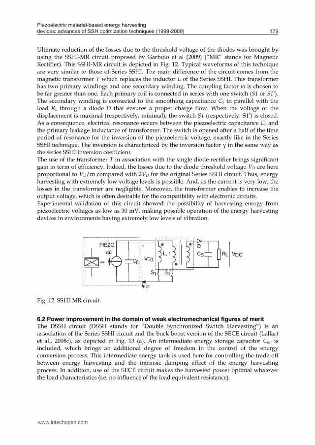
Ultimate reduction of the losses due to the threshold voltage of the diodes was brought by using the SSHI-MR circuit proposed by Garbuio et al (2009) (“MR” stands for Magnetic Rectifier). This SSHI-MR circuit is depicted in Fig. 12. Typical waveforms of this technique are very similar to those of Series SSHI. The main difference of the circuit comes from the magnetic transformer T which replaces the inductor L of the Series SSHI. This transformer has two primary windings and one secondary winding. The coupling factor m is chosen to be far greater than one. Each primary coil is connected in series with one switch (S1 or S1’). The secondary winding is connected to the smoothing capacitance CS in parallel with the load RL through a diode D that ensures a proper charge flow. When the voltage or the displacement is maximal (respectively, minimal), the switch S1 (respectively, S1’) is closed. As a consequence, electrical resonance occurs between the piezoelectric capacitance C0 and the primary leakage inductance of transformer. The switch is opened after a half of the time period of resonance for the inversion of the piezoelectric voltage, exactly like in the Series SSHI technique. The inversion is characterized by the inversion factor γ in the same way as the series SSHI inversion coefficient. The use of the transformer T in association with the single diode rectifier brings significant gain in term of efficiency. Indeed, the losses due to the diode threshold voltage VD are here proportional to VD/m compared with 2VD for the original Series SSHI circuit. Thus, energy harvesting with extremely low voltage levels is possible. And, as the current is very low, the losses in the transformer are negligible. Moreover, the transformer enables to increase the output voltage, which is often desirable for the compatibility with electronic circuits. Experimental validation of this circuit showed the possibility of harvesting energy from piezoelectric voltages as low as 30 mV, making possible operation of the energy harvesting devices in environments having extremely low levels of vibration.
Fig. 12. SSHI-MR circuit.
6.2 Power improvement in the domain of weak electromechanical figures of merit The DSSH circuit (DSSH stands for “Double Synchronized Switch Harvesting”) is an association of the Series SSHI circuit and the buck-boost version of the SECE circuit (Lallart et al., 2008c), as depicted in Fig. 13 (a). An intermediate energy storage capacitor Cint is included, which brings an additional degree of freedom in the control of the energy conversion process. This intermediate energy tank is used here for controlling the trade-off between energy harvesting and the intrinsic damping effect of the energy harvesting process. In addition, use of the SECE circuit makes the harvested power optimal whatever the load characteristics (i.e. no influence of the load equivalent resistance).
www.intechopen.com
Piezoelectric material-based energy harvesting devices: advances of SSH optimization techniques (1999-2009) 179
In the case of low voltages, the main problem comes from voltage drop across components, such as threshold voltage of the diodes used for voltage rectification, which significantly diminish efficiency of energy harvesting devices. This problem appears at low vibration level which results in a low piezoelectric voltage magnitude, typically below 1 or 2 volts. This problem becomes critical in the case of ultralow voltage such as that of MEMS-based (MicroElectroMechanical Systems) energy harvesting devices, whose magnitude reaches barely a few tens of milivolts. Indeed, such voltages are lower than the threshold voltage of the diodes commonly available. An approach for reducing the voltage drops consists basically to limit the number of diodes used for voltage rectification. In this context, Makiara et al. (2006) have proposed a half-bridge circuit for the Parallel SSHI technique. The voltage rectifier requires only two diodes instead of four in the original Parallel SSHI circuit (Fig. 11 (a)). As a consequence, power loss inherent to the diodes threshold voltage is divided by two. The control principle of the switch is the following: when the piezoelectric voltage is maximal, corresponding to a maximum of mechanical displacement, the switch is toggled on “point 2”. And, conversely, when the piezoelectric voltage is minimal, the switch is toggled on “point 1”. However, despite very simple control principle, truly self-powered implementation of this half-bridge Parallel SSHI circuit is difficult in practice. Indeed, holding on the electronic switch during a half period of vibration consumes a lot of energy compared to the brief on state required by the original Parallel SSHI. This is why theoretical power gain brought by this circuit could have been verified using external power source for the control circuitry only. Another half-bridge circuit was proposed by Lallart et al. (2008a) for implementation of the Series SSHI technique. The switches control principle is the following: when the piezoelectric voltage reaches a maximum the switch S1 is briefly turned on (during a time period equivalent to a half of the resonance period of the LC0 circuit) and conversely when this voltage reaches a minimum the switch S2 is briefly turned off. Compared to the original Series SSHI, voltage drop due to the rectifier is limited to the diode threshold voltage VD instead of 2VD. This makes a big difference in terms of efficiency when the piezoelectric voltage magnitude is only a few times bigger than VD. Experimental validation of this circuit with truly self-powered electronic control circuitry showed for instance more than 60% increase of the power supplied by the energy harvesting device compared to the original Series SSHI with piezoelectric voltage magnitude below 2 V.
Point 1
L
Point 2
(a) (b)
CS
Piezo
V VDC
RL
Fig. 11. Half-bridge SSH circuits: (a) Parallel SSHI (b) Series SSHI.
Ultimate reduction of the losses due to the threshold voltage of the diodes was brought by using the SSHI-MR circuit proposed by Garbuio et al (2009) (“MR” stands for Magnetic Rectifier). This SSHI-MR circuit is depicted in Fig. 12. Typical waveforms of this technique are very similar to those of Series SSHI. The main difference of the circuit comes from the magnetic transformer T which replaces the inductor L of the Series SSHI. This transformer has two primary windings and one secondary winding. The coupling factor m is chosen to be far greater than one. Each primary coil is connected in series with one switch (S1 or S1’). The secondary winding is connected to the smoothing capacitance CS in parallel with the load RL through a diode D that ensures a proper charge flow. When the voltage or the displacement is maximal (respectively, minimal), the switch S1 (respectively, S1’) is closed. As a consequence, electrical resonance occurs between the piezoelectric capacitance C0 and the primary leakage inductance of transformer. The switch is opened after a half of the time period of resonance for the inversion of the piezoelectric voltage, exactly like in the Series SSHI technique. The inversion is characterized by the inversion factor γ in the same way as the series SSHI inversion coefficient. The use of the transformer T in association with the single diode rectifier brings significant gain in term of efficiency. Indeed, the losses due to the diode threshold voltage VD are here proportional to VD/m compared with 2VD for the original Series SSHI circuit. Thus, energy harvesting with extremely low voltage levels is possible. And, as the current is very low, the losses in the transformer are negligible. Moreover, the transformer enables to increase the output voltage, which is often desirable for the compatibility with electronic circuits. Experimental validation of this circuit showed the possibility of harvesting energy from piezoelectric voltages as low as 30 mV, making possible operation of the energy harvesting devices in environments having extremely low levels of vibration.
Fig. 12. SSHI-MR circuit.
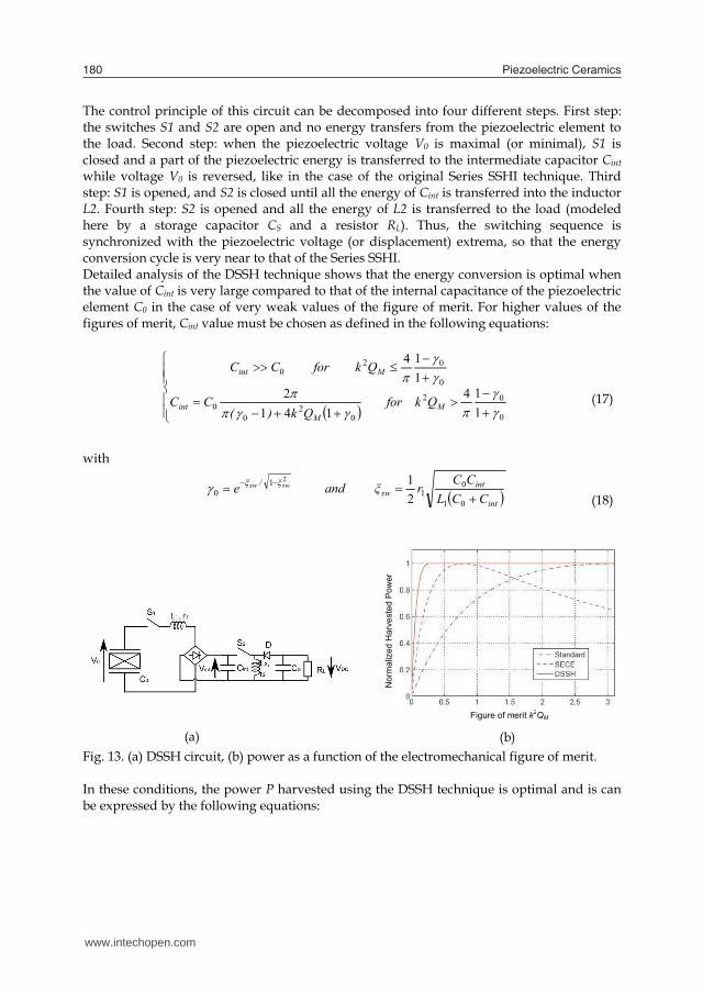
6.2 Power improvement in the domain of weak electromechanical figures of merit The DSSH circuit (DSSH stands for “Double Synchronized Switch Harvesting”) is an association of the Series SSHI circuit and the buck-boost version of the SECE circuit (Lallart et al., 2008c), as depicted in Fig. 13 (a). An intermediate energy storage capacitor Cint is included, which brings an additional degree of freedom in the control of the energy conversion process. This intermediate energy tank is used here for controlling the trade-off between energy harvesting and the intrinsic damping effect of the energy harvesting process. In addition, use of the SECE circuit makes the harvested power optimal whatever the load characteristics (i.e. no influence of the load equivalent resistance).
www.intechopen.com
Piezoelectric Ceramics180
The control principle of this circuit can be decomposed into four different steps. First step: the switches S1 and S2 are open and no energy transfers from the piezoelectric element to the load. Second step: when the piezoelectric voltage V0 is maximal (or minimal), S1 is closed and a part of the piezoelectric energy is transferred to the intermediate capacitor Cint while voltage V0 is reversed, like in the case of the original Series SSHI technique. Third step: S1 is opened, and S2 is closed until all the energy of Cint is transferred into the inductor L2. Fourth step: S2 is opened and all the energy of L2 is transferred to the load (modeled here by a storage capacitor CS and a resistor RL). Thus, the switching sequence is synchronized with the piezoelectric voltage (or displacement) extrema, so that the energy conversion cycle is very near to that of the Series SSHI. Detailed analysis of the DSSH technique shows that the energy conversion is optimal when the value of Cint is very large compared to that of the internal capacitance of the piezoelectric element C0 in the case of very weak values of the figure of merit. For higher values of the figures of merit, Cint value must be chosen as defined in the following equations:
0
02
02
00
0
020
114
1412
114
MM
int
Mint
Qk for Qk)(
CC
Qk orf CC
(17)
with
int
intsw
/
CCLCC
rξ and e swsw 01
01
10 2
12 (18)
(a) (b)
Figure of merit k2QM
Nor
mal
ized
Har
vest
ed P
ower
Fig. 13. (a) DSSH circuit, (b) power as a function of the electromechanical figure of merit. In these conditions, the power P harvested using the DSSH technique is optimal and is can be expressed by the following equations:
0
0221
420
0221
42
200
20
114
8
114
141
1
Mr
Mr
M2
M2
Qk for C
UMP
Qk orf C
UM
Qk
Qk2P
(19)
Variation of the normalized power harvested by the DSSH, SECE and Standard techniques as a function of the figure of merit k2QM is compared in Fig. 13 (b). These charts clearly show the interest of the DSSH technique, whose power is much more important than that of the two other techniques for very weak values of the electromechanical figure of merit. From another point of view, using the DSSH technique reduces the constraints of design of the electromechanical part in terms of quality factor and electromechanical coupling. In particular, the amount of piezoelectric material can be drastically reduced compared to energy harvesting devices using the standard technique. The DSSH technique presents significant advantages for energy harvesting, but its practical implementation is a little bit more delicate than that of the SECE or the SSHI techniques. Truly self-powered control circuit of the DSSH has been demonstrated, and despites the cumulated losses of the two conversion stages, performances of this technique remain much better in practice than that of the standard and SECE techniques in the domain of weak figures of merit.
7. Conclusion
Piezoelectric materials are of major interest for high efficiency, low-power energy harvesting from ambient vibration. Owing to decrease of power consumption of electronic devices, increasing variety applications could benefit of such “infinite” lifespan micro-sources of energy. Based on a single degree of freedom {spring + mass + damper} mechanical system associated to the piezoelectric electromechanical coupling, this chapter analysed first the electromechanical power converted in association with the so-called standard electrical interface, commonly found in piezoelectric energy harvesting devices. Then, the original SSH techniques, derived from semi-passive piezoelectric damping techniques, were presented. Compared to the Standard electrical energy processing, SSHI (series and parallel) and SECE techniques enable significant improvement of harvested power. With the seismic mechanical structure considered here, the power is in particular strongly increased at weak values of the electromechanical figure of merit k2QM. As a result, compared to the standard approach, the amount of piezoelectric material can be reduced by factor 4 or more, thus enabling the design of compact, high efficiency energy harvesting devices. Reduction of the power dependence to the excitation frequency is another advantage brought by these techniques. Practical interest of the proposed approach has been shown in an energy harvesting devices designed for supplying the nodes of a wireless network used for structural health monitoring (Guyomar et al., 2007). Interest of these techniques for pyroelectric energy harvesting has also been demonstrated (Sebald et al., 2008).
www.intechopen.com

Piezoelectric material-based energy harvesting devices: advances of SSH optimization techniques (1999-2009) 181
The control principle of this circuit can be decomposed into four different steps. First step: the switches S1 and S2 are open and no energy transfers from the piezoelectric element to the load. Second step: when the piezoelectric voltage V0 is maximal (or minimal), S1 is closed and a part of the piezoelectric energy is transferred to the intermediate capacitor Cint while voltage V0 is reversed, like in the case of the original Series SSHI technique. Third step: S1 is opened, and S2 is closed until all the energy of Cint is transferred into the inductor L2. Fourth step: S2 is opened and all the energy of L2 is transferred to the load (modeled here by a storage capacitor CS and a resistor RL). Thus, the switching sequence is synchronized with the piezoelectric voltage (or displacement) extrema, so that the energy conversion cycle is very near to that of the Series SSHI. Detailed analysis of the DSSH technique shows that the energy conversion is optimal when the value of Cint is very large compared to that of the internal capacitance of the piezoelectric element C0 in the case of very weak values of the figure of merit. For higher values of the figures of merit, Cint value must be chosen as defined in the following equations:
0
02
02
00
0
020
114
1412
114
MM
int
Mint
Qk for Qk)(
CC
Qk orf CC
(17)
with
int
intsw
/
CCLCC
rξ and e swsw 01
01
10 2
12 (18)
(a) (b)
Figure of merit k2QM
Nor
mal
ized
Har
vest
ed P
ower
Fig. 13. (a) DSSH circuit, (b) power as a function of the electromechanical figure of merit. In these conditions, the power P harvested using the DSSH technique is optimal and is can be expressed by the following equations:
0
0221
420
0221
42
200
20
114
8
114
141
1
Mr
Mr
M2
M2
Qk for C
UMP
Qk orf C
UM
Qk
Qk2P
(19)
Variation of the normalized power harvested by the DSSH, SECE and Standard techniques as a function of the figure of merit k2QM is compared in Fig. 13 (b). These charts clearly show the interest of the DSSH technique, whose power is much more important than that of the two other techniques for very weak values of the electromechanical figure of merit. From another point of view, using the DSSH technique reduces the constraints of design of the electromechanical part in terms of quality factor and electromechanical coupling. In particular, the amount of piezoelectric material can be drastically reduced compared to energy harvesting devices using the standard technique. The DSSH technique presents significant advantages for energy harvesting, but its practical implementation is a little bit more delicate than that of the SECE or the SSHI techniques. Truly self-powered control circuit of the DSSH has been demonstrated, and despites the cumulated losses of the two conversion stages, performances of this technique remain much better in practice than that of the standard and SECE techniques in the domain of weak figures of merit.
7. Conclusion
Piezoelectric materials are of major interest for high efficiency, low-power energy harvesting from ambient vibration. Owing to decrease of power consumption of electronic devices, increasing variety applications could benefit of such “infinite” lifespan micro-sources of energy. Based on a single degree of freedom {spring + mass + damper} mechanical system associated to the piezoelectric electromechanical coupling, this chapter analysed first the electromechanical power converted in association with the so-called standard electrical interface, commonly found in piezoelectric energy harvesting devices. Then, the original SSH techniques, derived from semi-passive piezoelectric damping techniques, were presented. Compared to the Standard electrical energy processing, SSHI (series and parallel) and SECE techniques enable significant improvement of harvested power. With the seismic mechanical structure considered here, the power is in particular strongly increased at weak values of the electromechanical figure of merit k2QM. As a result, compared to the standard approach, the amount of piezoelectric material can be reduced by factor 4 or more, thus enabling the design of compact, high efficiency energy harvesting devices. Reduction of the power dependence to the excitation frequency is another advantage brought by these techniques. Practical interest of the proposed approach has been shown in an energy harvesting devices designed for supplying the nodes of a wireless network used for structural health monitoring (Guyomar et al., 2007). Interest of these techniques for pyroelectric energy harvesting has also been demonstrated (Sebald et al., 2008).
www.intechopen.com
Piezoelectric Ceramics182
This paper presented then the techniques recently derived from the original SSH techniques. Half-bridge parallel and series SSHI interfaces have increased the efficiency of the related techniques in the case of low piezoelectric voltages, making possible the energy harvesting from low-level vibrations. The SSHI-MR circuit has then even more reduced the problems related to voltage drops, so that energy can be harvested in the case of piezoelectric voltages as low as a few tens of millivolts. The DSSH interface, which was derived from both the series SSHI and SECE circuits, showed the possibility of dramatically increasing the power harvested using electromechanical structures with extremely weak figures of merit. The general principle of processing the piezoelectric voltage synchronously with the mechanical excitation offers large degrees of freedom for power improvement as well as reduction of the sensitivity to variations of the load and to drift of the excitation frequency, so it is highly probable that novel interfaces based on the original SSH principle will be proposed in the future. Current challenges in the field of piezoelectric energy harvesting concern the robustness to frequency mistuning and the improvement of the power harvested from broadband vibrations. Indeed, efficient piezoelectric energy harvesters operate in resonant mode. Consequently they exhibit narrow bandwidth and only a small part of available energy can be harvested. Among solutions investigated to address this problem, the most promising way is based on bistable electromechanical structures (Eturk et al, 2009; Stanton et al, 2009). Compared to usual resonators, these non linear resonators exhibit enlarged bandwidth while keeping advantage of high power conversion capability. Ongoing works aim at evaluating the interest of associating the SSH techniques with the non linear piezoelectric resonators.
8. References
Anton, S. R. & Sodano, H. A. (2007). A review of power harvesting usingpiezoelectric materials (2003–2006). Smart Materials and Structures. 16, R1–R21.
Badel, A.; Lefeuvre, E.; Richard, C. and Guyomar, D. (2005). Efficiency enhancement of a piezoelectric energy harvesting device in pulsed operation by synchronous charge inversion. Journal of Intelligent Materials Systems and Structures, Vol. 16, N°10, 889-901.
Badel, A.; Lagache, M; Guyomar, D.; Lefeuvre, E. & Richard, C. (2007). Finite element and simple lumped modeling for flexural nonlinear semi-passive damping. Journal of Intelligent Material Systems and Structures, Vol. 18, Issue 7, 727-742.
Energy Harvesting Forum. Energy Harvesting Electronic solutions for Wireless Sensor networks and Control Systems. (Online). http://www.energyharvesting.net/
Erturk, A.; Hoffmann, J. & Inman, D. J. (2009). A piezomagnetoelastic structure for broadband vibration energy harvesting. Applied Physics Letters, 94.
Garbuio, L.; Lallart, M.; Guyomar, D.; Richard, C. & Audigier D. (2009). Mechanical Energy Harvester With Ultralow Threshold Rectification Based on SSHI Nonlinear Technique. IEEE Transactions on Industrial Electronics, Vol. 56, No. 4, 1048-1056.
Guyomar, D.; Badel, A.; Lefeuvre, E. & Richard, C. (2005). Towards Energy Harvesting using Active Materials and Conversion Improvement by Nonlinear Processing. IEEE Transactions on UFFC, vol. 52, no. 4, 584-595.
Guyomar, D.; Jayet, Y.; Petit, L.; Lefeuvre, E.; Monnier, T.; Richard; C. & Lallart, M. (2007). Synchronized switch harvesting applied to selfpowered smart systems: Piezoactive microgenerators for autonomous wireless transmitters. Sensors and Actuators A: Physical, Vol. 138, N°1, 151-160.
Horowitz, S.; Kasyap, A.; Liu, F.; Johnson, D.; Nishida, T.; Ngo, K. Sheplak, M. & Cattafesta, L. (2002). Technology Development for Self-Powered Sensors. AIAA 1st Control Flow Conference Proceedings, pp. 2-10, St. Louis, June 2002, AIAA, Reston.
Krikke D. (2005). Sunrise for Energy Harvesting Products. IEEE Pervasive Computing, Issue Date: January 2005, 4-8.
Lallart, M. & Guyomar, D. (2008a). An optimized self-powered switching circuit for non-linear energy harvesting with low voltage output. Smart Materials and Structures, 17, N°3, 1-8.
Lallart, M.; Lefeuvre, E.; Richard, C. & Guyomar, D. (2008b). Self-Powered Circuit for Broadband, Multimodal Piezoelectric Vibration Control. Sensors and Actuators A: Physical, vol. 143, N°2, 377-382.
Lallart, M.; Garbuio, L.; Petit, L.; Richard C. & Guyomar D. (2008c). Double Synchronized Switch Harvesting (DSSH): A New Energy Harvesting Scheme for Efficient Energy Extraction. IEEE Transactions on UFFC, Vol. 55, No. 10, 2119-2130.
Lallart, M.; Garbuio, L.; Petit, L.; Richard C. & Guyomar D. (2010). Low-cost piezoelectric voltage inverter for outstanding performance in piezoelectric energy harvesting. IEEE Transactions on UFFC, vol. 57, no. 2, 281-291.
Lefeuvre, E.; Badel, A.; Richard, C. & Guyomar, D. (2004). High Performance Piezoelectric Vibration Energy Reclamation. SPIE Proceedings, Vol. 5390, 379-387.
Lefeuvre, E.; Badel, A.; Richard, C. & Guyomar, D. (2006a). A comparison between several vibration-powered piezoelectric generators for standalone systems. Sensors and Actuators A: Physical, vol. 126, issue 2, 405-416.
Lefeuvre, E.; Audigier, D.; Richard, C. & and Guyomar, D. (2006b). Buck-Boost Converter for Sensorless Power Optimization of Piezoelectric Energy Harvester. IEEE Transactions on Power Electronics, Vol. 22, N°5, 2018-2025.
Lefeuvre, E.; Badel, A.; Richard, C. & Guyomar, D. (2007). Energy harvesting using piezoelectric materials: case of random vibrations. Journal of Electroceramics, Vol. 19, 349-355.
Lefeuvre, E.; Sebald, G.; Guyomar, D.; Lallart, M. & Richard, C. (2009). Materials, structures and power interfaces for efficient piezoelectric energy harvesting. Journal of Electroceramics, vol. 22, 171-179.
Makihara, K.; Onoda, J. & Miyakawa, T. (2006). Low energy dissipation electric circuit for energy harvesting. Smart Materials and Structures, 15, 1493–1498.
McLean Nicolson A. (1931). Piezoelectric Crystal Converter. US Patent N°1975517. Mitcheson, P. D.; Green T. C. & Yeatman E. M. (2007). Power processing circuits for
electromagnetic, electrostatic and piezoelectric inertial energy scavengers. Microsystem Technologies 13:1629–1635.
Ottman, G. K.; Bhatt, A. C.; Hofmann, H. & Lesieutre, G. A. (2002). Adaptive piezoelectric energy harvesting circuit for wireless remote power supply. IEEE Transactions on Power Electronics, vol. 17, 669–676.
www.intechopen.com
Piezoelectric material-based energy harvesting devices: advances of SSH optimization techniques (1999-2009) 183
This paper presented then the techniques recently derived from the original SSH techniques. Half-bridge parallel and series SSHI interfaces have increased the efficiency of the related techniques in the case of low piezoelectric voltages, making possible the energy harvesting from low-level vibrations. The SSHI-MR circuit has then even more reduced the problems related to voltage drops, so that energy can be harvested in the case of piezoelectric voltages as low as a few tens of millivolts. The DSSH interface, which was derived from both the series SSHI and SECE circuits, showed the possibility of dramatically increasing the power harvested using electromechanical structures with extremely weak figures of merit. The general principle of processing the piezoelectric voltage synchronously with the mechanical excitation offers large degrees of freedom for power improvement as well as reduction of the sensitivity to variations of the load and to drift of the excitation frequency, so it is highly probable that novel interfaces based on the original SSH principle will be proposed in the future. Current challenges in the field of piezoelectric energy harvesting concern the robustness to frequency mistuning and the improvement of the power harvested from broadband vibrations. Indeed, efficient piezoelectric energy harvesters operate in resonant mode. Consequently they exhibit narrow bandwidth and only a small part of available energy can be harvested. Among solutions investigated to address this problem, the most promising way is based on bistable electromechanical structures (Eturk et al, 2009; Stanton et al, 2009). Compared to usual resonators, these non linear resonators exhibit enlarged bandwidth while keeping advantage of high power conversion capability. Ongoing works aim at evaluating the interest of associating the SSH techniques with the non linear piezoelectric resonators.
8. References
Anton, S. R. & Sodano, H. A. (2007). A review of power harvesting usingpiezoelectric materials (2003–2006). Smart Materials and Structures. 16, R1–R21.
Badel, A.; Lefeuvre, E.; Richard, C. and Guyomar, D. (2005). Efficiency enhancement of a piezoelectric energy harvesting device in pulsed operation by synchronous charge inversion. Journal of Intelligent Materials Systems and Structures, Vol. 16, N°10, 889-901.
Badel, A.; Lagache, M; Guyomar, D.; Lefeuvre, E. & Richard, C. (2007). Finite element and simple lumped modeling for flexural nonlinear semi-passive damping. Journal of Intelligent Material Systems and Structures, Vol. 18, Issue 7, 727-742.
Energy Harvesting Forum. Energy Harvesting Electronic solutions for Wireless Sensor networks and Control Systems. (Online). http://www.energyharvesting.net/
Erturk, A.; Hoffmann, J. & Inman, D. J. (2009). A piezomagnetoelastic structure for broadband vibration energy harvesting. Applied Physics Letters, 94.
Garbuio, L.; Lallart, M.; Guyomar, D.; Richard, C. & Audigier D. (2009). Mechanical Energy Harvester With Ultralow Threshold Rectification Based on SSHI Nonlinear Technique. IEEE Transactions on Industrial Electronics, Vol. 56, No. 4, 1048-1056.
Guyomar, D.; Badel, A.; Lefeuvre, E. & Richard, C. (2005). Towards Energy Harvesting using Active Materials and Conversion Improvement by Nonlinear Processing. IEEE Transactions on UFFC, vol. 52, no. 4, 584-595.
Guyomar, D.; Jayet, Y.; Petit, L.; Lefeuvre, E.; Monnier, T.; Richard; C. & Lallart, M. (2007). Synchronized switch harvesting applied to selfpowered smart systems: Piezoactive microgenerators for autonomous wireless transmitters. Sensors and Actuators A: Physical, Vol. 138, N°1, 151-160.
Horowitz, S.; Kasyap, A.; Liu, F.; Johnson, D.; Nishida, T.; Ngo, K. Sheplak, M. & Cattafesta, L. (2002). Technology Development for Self-Powered Sensors. AIAA 1st Control Flow Conference Proceedings, pp. 2-10, St. Louis, June 2002, AIAA, Reston.
Krikke D. (2005). Sunrise for Energy Harvesting Products. IEEE Pervasive Computing, Issue Date: January 2005, 4-8.
Lallart, M. & Guyomar, D. (2008a). An optimized self-powered switching circuit for non-linear energy harvesting with low voltage output. Smart Materials and Structures, 17, N°3, 1-8.
Lallart, M.; Lefeuvre, E.; Richard, C. & Guyomar, D. (2008b). Self-Powered Circuit for Broadband, Multimodal Piezoelectric Vibration Control. Sensors and Actuators A: Physical, vol. 143, N°2, 377-382.
Lallart, M.; Garbuio, L.; Petit, L.; Richard C. & Guyomar D. (2008c). Double Synchronized Switch Harvesting (DSSH): A New Energy Harvesting Scheme for Efficient Energy Extraction. IEEE Transactions on UFFC, Vol. 55, No. 10, 2119-2130.
Lallart, M.; Garbuio, L.; Petit, L.; Richard C. & Guyomar D. (2010). Low-cost piezoelectric voltage inverter for outstanding performance in piezoelectric energy harvesting. IEEE Transactions on UFFC, vol. 57, no. 2, 281-291.
Lefeuvre, E.; Badel, A.; Richard, C. & Guyomar, D. (2004). High Performance Piezoelectric Vibration Energy Reclamation. SPIE Proceedings, Vol. 5390, 379-387.
Lefeuvre, E.; Badel, A.; Richard, C. & Guyomar, D. (2006a). A comparison between several vibration-powered piezoelectric generators for standalone systems. Sensors and Actuators A: Physical, vol. 126, issue 2, 405-416.
Lefeuvre, E.; Audigier, D.; Richard, C. & and Guyomar, D. (2006b). Buck-Boost Converter for Sensorless Power Optimization of Piezoelectric Energy Harvester. IEEE Transactions on Power Electronics, Vol. 22, N°5, 2018-2025.
Lefeuvre, E.; Badel, A.; Richard, C. & Guyomar, D. (2007). Energy harvesting using piezoelectric materials: case of random vibrations. Journal of Electroceramics, Vol. 19, 349-355.
Lefeuvre, E.; Sebald, G.; Guyomar, D.; Lallart, M. & Richard, C. (2009). Materials, structures and power interfaces for efficient piezoelectric energy harvesting. Journal of Electroceramics, vol. 22, 171-179.
Makihara, K.; Onoda, J. & Miyakawa, T. (2006). Low energy dissipation electric circuit for energy harvesting. Smart Materials and Structures, 15, 1493–1498.
McLean Nicolson A. (1931). Piezoelectric Crystal Converter. US Patent N°1975517. Mitcheson, P. D.; Green T. C. & Yeatman E. M. (2007). Power processing circuits for
electromagnetic, electrostatic and piezoelectric inertial energy scavengers. Microsystem Technologies 13:1629–1635.
Ottman, G. K.; Bhatt, A. C.; Hofmann, H. & Lesieutre, G. A. (2002). Adaptive piezoelectric energy harvesting circuit for wireless remote power supply. IEEE Transactions on Power Electronics, vol. 17, 669–676.
www.intechopen.com

Piezoelectric Ceramics184
Ottman, G. K.; Bhatt, A. C.; Hofmann, H. & Lesieutre, G. A. (2003). Optimized Piezoelectric Energy Harvesting Circuit Using Step-Down Converter in Discontinuous Conduction Mode. IEEE Transactions on Power Electronics, vol. 18, 696–703.
Richard, C.; Guyomar, D.; Audigier, D. & Ching, G. (1999). Semi-passive damping using continuous switching of a piezoelectric device. SPIE Proceedings, Vol. 3672, 104-111.
Richard, C.; Guyomar, D.; Audigier, D. & Bassaler, H. (2000). Enhanced semi-passive damping using continuous switching of a piezoelectric device on an inductor. SPIE Proceedings, Vol. 3989, 288-299.
Richards, C. D.; Anderson, M. J.; Bahr D. F. & Richards, R. F. (2004). Efficiency of energy conversion for devices containing a piezoelectric component. Journal of Micromechanics and Microengineering, Vol. 14, 717-721.
Roundy, S. & Wright, P. K. (2004). A piezoelectric vibration based generator for wireless electronics. Smart Materials and Structures, 13, 1131–1142.
Sebald, G.; Lefeuvre, E. & Guyomar, D. (2008). Pyroelectric energy conversion: optimization principles. IEEE Transaction on Ultrasonics, Ferroelectrics and Frequency Control, Vol. 55, n°3, 538-551.
Shu, Y. C. & Lien, I. C. (2006). Analysis of power output for piezoelectric energy harvesting systems. Smart Materials and Structures, 15, 1499–1512.
Shu, Y. C. & Lien, I. C. (2007). An improved analysis of the SSHI interface in piezoelectric energy harvesting. Smart Materials and Structures, 16, 2253-2264.
Shu, Y. C.; Lien, I. C.; Wu, W. J. and Shiu, S. M. (2009). Comparisons between parallel- and series-SSHI interfaces adopted by piezoelectric energy harvesting systems, Proceedings of SPIE 16th International Symposium on Smart Structures and Materials, vol. 7288, San Diego, California, april 2009.
Sodano, H. A.; Inman, D. J. & Park, G. (2004). A Review of Power Harvesting from Vibration using Piezoelectric Materials. The Shock and Vibration Digest, Vol. 36, No. 3, 197–205.
Stanton, S. C.; McGehee, C. C. & Mann, B. P. (2009). Reversible hysteresis for broadband magnetopiezoelastic energy harvesting. Applied Physics Letters, 95.
Taylor, G. W.; Burns, J. R.; Kammann, S. M.; Powers, W. B. & Welsh, T. R. (2001). The energy harvesting eel: a small subsurface ocean/river power generator. IEEE Journal of Ocean Engineering, Vol. 26, 539-547
Wang, Q. M. & Cross, L. E. (1999). Constitutive equations of symmetrical triple layer piezoelectric benders. IEEE Transactions on Ultrasonics, Ferroelectrics and Frequency Control, Vol. 46, 1343-1351.
www.intechopen.com

Piezoelectric CeramicsEdited by Ernesto Suaste-Gomez
ISBN 978-953-307-122-0Hard cover, 294 pagesPublisher SciyoPublished online 05, October, 2010Published in print edition October, 2010
InTech EuropeUniversity Campus STeP Ri Slavka Krautzeka 83/A 51000 Rijeka, Croatia Phone: +385 (51) 770 447 Fax: +385 (51) 686 166www.intechopen.com
InTech ChinaUnit 405, Office Block, Hotel Equatorial Shanghai No.65, Yan An Road (West), Shanghai, 200040, China
Phone: +86-21-62489820 Fax: +86-21-62489821
This book reviews a big window of opportunity for piezoelectric ceramics, such as new materials, materialcombinations, structures, damages and porosity effects. In addition, applications of sensors, actuators,transducers for ultrasonic imaging, positioning systems, energy harvesting, biomedical and microelectronicdevices are described. The book consists of fourteen chapters. The genetic algorithm is used for identificationof RLC parameters in the equivalent electrical circuit of piezoelectric transducers. Concept and developmentperspectives for piezoelectric energy harvesting are described. The characterization of principal properties andadvantages of a novel device called ceramic-controlled piezoelectric with a Pt wire implant is included. Bio-compatibility studies between piezoelectric ceramic material and biological cell suspension are exposed. Thus,piezoelectric ceramics have been a very favorable solution as a consequence of its high energy density andthe variety of fabrication techniques to obtain bulk or thin films devices. Finally, the readers will perceive atrend analysis and examine recent developments in different fields of applications of piezoelectric ceramics.
How to referenceIn order to correctly reference this scholarly work, feel free to copy and paste the following:
Elie Lefeuvre, Mickail Lallart, Claude Richard and Daniel Guyomar (2010). Piezoelectric Material-BasedEnergy Harvesting Devices: Advance of SSH Optimization Techniques (1999-2009), Piezoelectric Ceramics,Ernesto Suaste-Gomez (Ed.), ISBN: 978-953-307-122-0, InTech, Available from:http://www.intechopen.com/books/piezoelectric-ceramics/piezoelectric-material-based-energy-harvesting-devices-advance-of-ssh-optimization-techniques-1999-2

© 2010 The Author(s). Licensee IntechOpen. This chapter is distributedunder the terms of the Creative Commons Attribution-NonCommercial-ShareAlike-3.0 License, which permits use, distribution and reproduction fornon-commercial purposes, provided the original is properly cited andderivative works building on this content are distributed under the samelicense.