Embed Size (px)
Citation preview

Student Notes:
ELFINI Structural Analysis������������
Copyright DASSAULT SYSTEMES 1
Cop
yrig
ht D
AS
SA
ULT
SY
STE
ME
S
ELFINI Structural Analysis
CATIA V5 TrainingFoils
Version 5 Release 19January 2009
EDU_CAT_EN_EST_FF_V5R19

Student Notes:
ELFINI Structural Analysis������������
Copyright DASSAULT SYSTEMES 2
Cop
yrig
ht D
AS
SA
ULT
SY
STE
ME
S
About this courseObjectives of the courseUpon completion of this course you will be able to: - Use the advanced pre-processing capabilities (such as loads and boundary conditions) to create more realistic FE models. - Visualize the images of objects used for pre-processing (which is not possible in GPS). - Use advanced case features (such as Buckling, MultiLoads, Envelope) in addition to the standard Static and Frequency cases - Create your own result image templates, customize the post-processing result images, group selective entities in the result images, and create advanced reports
Targeted audienceMechanical Designers
PrerequisitesGenerative Part Structural Analysis Fundamentals, Generative Assembly Structural Analysis, FEM Surface Meshing 8 Hours
Student Notes:
ELFINI Structural Analysis������������
Copyright DASSAULT SYSTEMES 3
Cop
yrig
ht D
AS
SA
ULT
SY
STE
ME
S
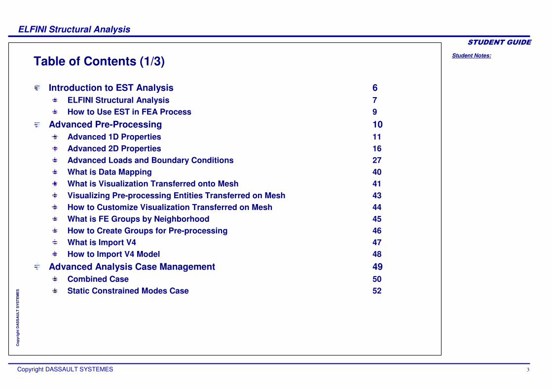
Table of Contents (1/3)
Introduction to EST Analysis 6ELFINI Structural Analysis 7How to Use EST in FEA Process 9
Advanced Pre-Processing 10Advanced 1D Properties 11Advanced 2D Properties 16Advanced Loads and Boundary Conditions 27What is Data Mapping 40What is Visualization Transferred onto Mesh 41Visualizing Pre-processing Entities Transferred on Mesh 43How to Customize Visualization Transferred on Mesh 44What is FE Groups by Neighborhood 45How to Create Groups for Pre-processing 46What is Import V4 47How to Import V4 Model 48
Advanced Analysis Case Management 49Combined Case 50Static Constrained Modes Case 52
Student Notes:
ELFINI Structural Analysis������������
Copyright DASSAULT SYSTEMES 4
Cop
yrig
ht D
AS
SA
ULT
SY
STE
ME
S
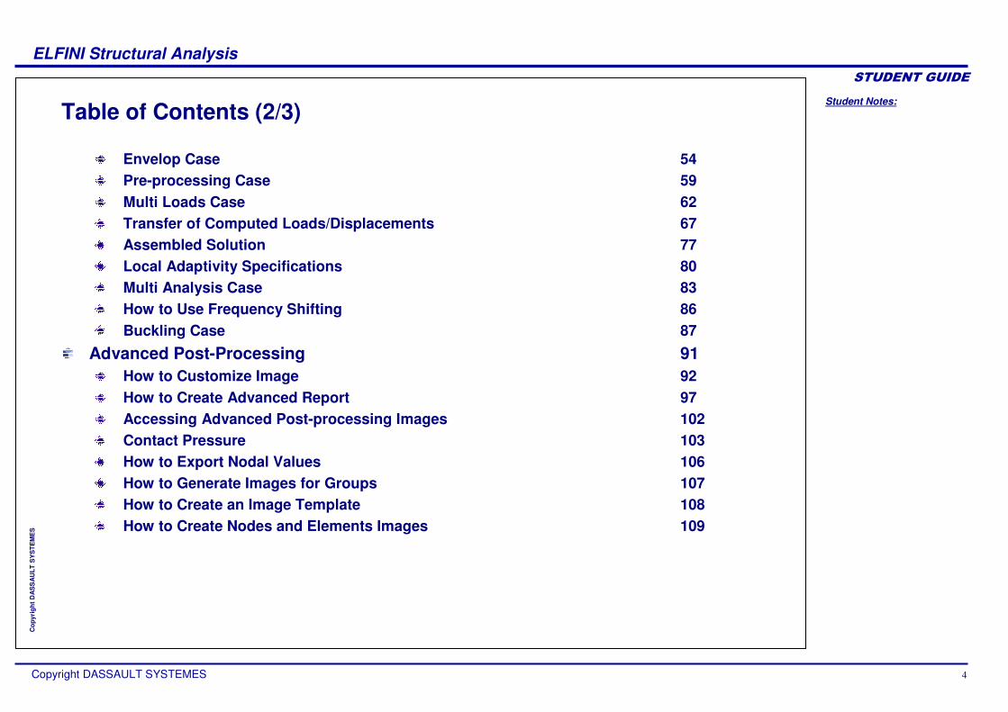
Table of Contents (2/3)
Envelop Case 54Pre-processing Case 59Multi Loads Case 62Transfer of Computed Loads/Displacements 67Assembled Solution 77Local Adaptivity Specifications 80Multi Analysis Case 83How to Use Frequency Shifting 86Buckling Case 87
Advanced Post-Processing 91How to Customize Image 92How to Create Advanced Report 97Accessing Advanced Post-processing Images 102Contact Pressure 103How to Export Nodal Values 106How to Generate Images for Groups 107How to Create an Image Template 108How to Create Nodes and Elements Images 109

Student Notes:
ELFINI Structural Analysis������������
Copyright DASSAULT SYSTEMES 5
Cop
yrig
ht D
AS
SA
ULT
SY
STE
ME
S
Table of Contents (3/3)
Local Sensors 110EST Functionalities 112Frequently Asked Questions 115To Sum Up 116

Student Notes:
ELFINI Structural Analysis������������
Copyright DASSAULT SYSTEMES 6
Cop
yrig
ht D
AS
SA
ULT
SY
STE
ME
S
Introduction to EST AnalysisIn this lesson, you will learn about the ELFINI Structural Analysis Workbench. The ELFINI Structural Analysis Workbench is entirely integrated both in GPS and GAS Workbenches.

Student Notes:
ELFINI Structural Analysis������������
Copyright DASSAULT SYSTEMES 7
Cop
yrig
ht D
AS
SA
ULT
SY
STE
ME
S
ELFINI Structural Analysis (1/2)
ELFINI Structural Analysis(EST) is an extension of GPS workbench and offers advanced functionalities for each step in Finite Element Analysis process.
Advanced pre-processing
Advanced Analysis Case Management
AdvancedPost-processing
Pre-processing(FE Modeling)
Computation (Solving FE Model)
Post-processing (View Results)
Mesh RefinementIterations
Create Reports
Student Notes:
ELFINI Structural Analysis������������
Copyright DASSAULT SYSTEMES 8
Cop
yrig
ht D
AS
SA
ULT
SY
STE
ME
S
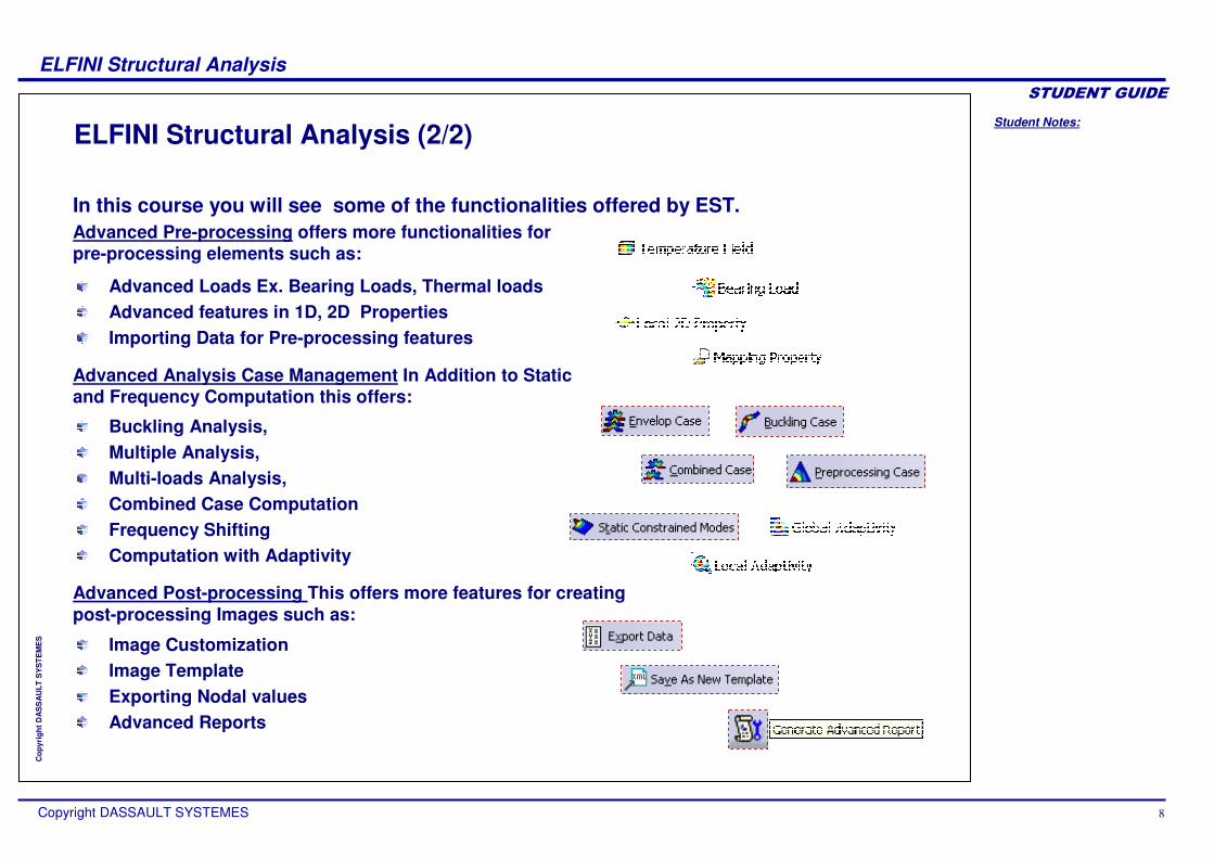
ELFINI Structural Analysis (2/2)
Advanced Pre-processing offers more functionalities for pre-processing elements such as:
Advanced Analysis Case Management In Addition to Static and Frequency Computation this offers:
Advanced Post-processing This offers more features for creating post-processing Images such as:
Advanced Loads Ex. Bearing Loads, Thermal loadsAdvanced features in 1D, 2D PropertiesImporting Data for Pre-processing features
Buckling Analysis,Multiple Analysis, Multi-loads Analysis,Combined Case ComputationFrequency ShiftingComputation with Adaptivity
Image CustomizationImage TemplateExporting Nodal valuesAdvanced Reports
In this course you will see some of the functionalities offered by EST.

Student Notes:
ELFINI Structural Analysis������������
Copyright DASSAULT SYSTEMES 9
Cop
yrig
ht D
AS
SA
ULT
SY
STE
ME
S
How to Use EST in FEA Process
Starting from a Part or an Assembly, open Generative Structural Analysis Workbench Advanced Pre-Processing
Visualize Pre-Processing specifications directly on Mesh
Advanced Post-Processing Customize image appearance Generate Advanced Reports
Advanced Computing Perform Computation with Multi Analysis Cases, including Buckling
1
3
2
You will see the general process flow in which different EST functionalities are required while performing FE Analysis.

Student Notes:
ELFINI Structural Analysis������������
Copyright DASSAULT SYSTEMES 10
Cop
yrig
ht D
AS
SA
ULT
SY
STE
ME
S
Advanced Pre-ProcessingIn this lesson, you will learn how Pre-Processing Elements are transferred onto the Mesh. Moreover, you will see different types of loads and pre-processing features only available in EST.
Advanced 1D PropertiesAdvanced 2D PropertiesAdvanced Loads and Boundary ConditionsWhat is Data MappingWhat is Visualization Transferred onto MeshVisualizing Pre-processing Entities Transferred on MeshHow to Customize Visualization Transferred on MeshWhat is FE Groups by NeighborhoodHow to Create Groups for Pre-processingWhat is Import V4How to Import V4 Model

Student Notes:
ELFINI Structural Analysis������������
Copyright DASSAULT SYSTEMES 11
Cop
yrig
ht D
AS
SA
ULT
SY
STE
ME
S
Advanced 1D PropertyYou will see the functionalities related to 1D property.

Student Notes:
ELFINI Structural Analysis������������
Copyright DASSAULT SYSTEMES 12
Cop
yrig
ht D
AS
SA
ULT
SY
STE
ME
S
What is Variable Cross-Section Beams
Variable beam factors lets you create a linear approximation of variable cross section beams. Activate ‘variable beam factors’ option. Two fields appear in the Beam Property dialog box. The Multiplication Factors on extremities frame will let you give a scaling factor on each side of the section. The beam will then be modeled as a sequence of constant section beams with linearly decreasing dimensions.

Student Notes:
ELFINI Structural Analysis������������
Copyright DASSAULT SYSTEMES 13
Cop
yrig
ht D
AS
SA
ULT
SY
STE
ME
S
Assigning Arbitrary Cross-section Using 1D Property
Select the section of the beam
New “Computed From Surface” item
Characteristics of the beam1 2 3
You can assign an arbitrary cross-section in addition to standard cross-sections available using “Beam From Surface” option. Section properties for selected section is automatically computed. Parameters Extend the beam property definition to any profile.
Student Notes:
ELFINI Structural Analysis������������
Copyright DASSAULT SYSTEMES 14
Cop
yrig
ht D
AS
SA
ULT
SY
STE
ME
S
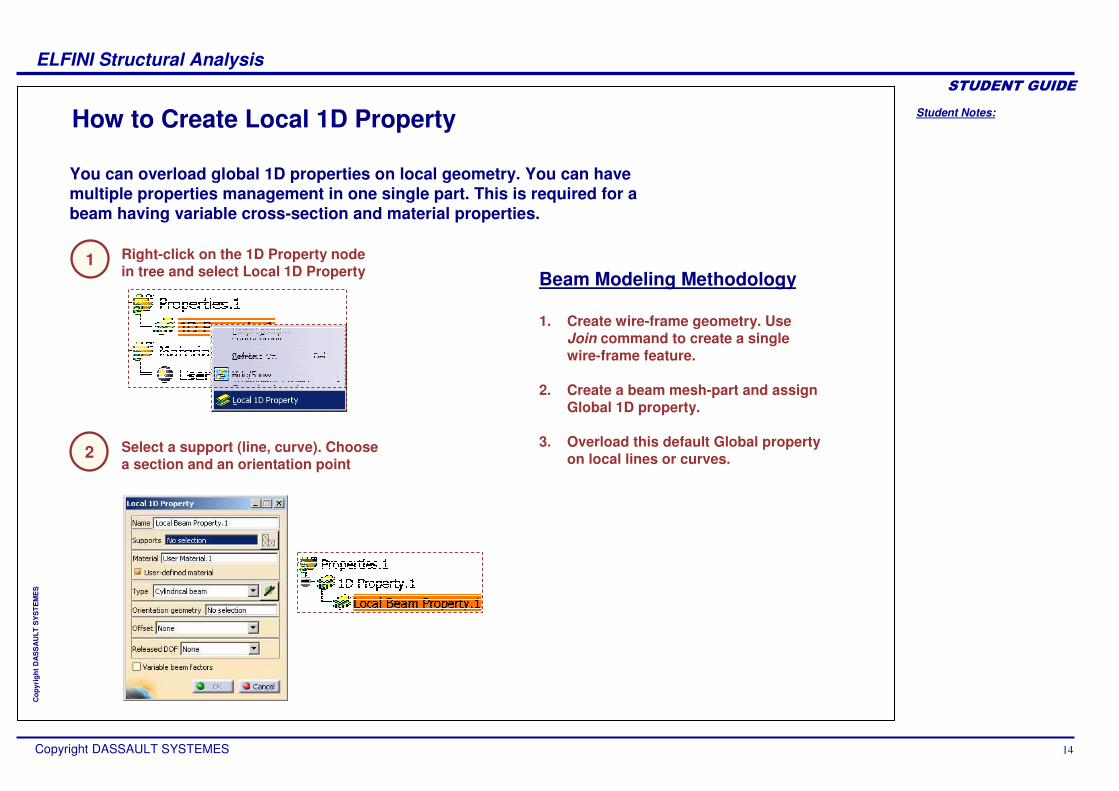
How to Create Local 1D Property
Select a support (line, curve). Choose a section and an orientation point
Right-click on the 1D Property node in tree and select Local 1D Property
1
2
You can overload global 1D properties on local geometry. You can have multiple properties management in one single part. This is required for a beam having variable cross-section and material properties.
Beam Modeling Methodology
1. Create wire-frame geometry. Use Join command to create a single wire-frame feature.
2. Create a beam mesh-part and assign Global 1D property.
3. Overload this default Global property on local lines or curves.

Student Notes:
ELFINI Structural Analysis������������
Copyright DASSAULT SYSTEMES 15
Cop
yrig
ht D
AS
SA
ULT
SY
STE
ME
S
What is 1D Property for Vehicle Conceptual Model
On the 1D mesh partOn the 1D property
A new type of 1D elements: BAR. Bar elements only have stiffness along their axis. They have three translation degrees of freedom per node. You can change the Physical Property type of 1D mesh as Bar or Beam.
In aeronautics, bar elements are usually used in combination with membrane or shear panel elements.
Membrane or shear panel
Membrane or shear panel element
Bar Elements surrounding membrane or shear panel element
Student Notes:
ELFINI Structural Analysis������������
Copyright DASSAULT SYSTEMES 16
Cop
yrig
ht D
AS
SA
ULT
SY
STE
ME
S
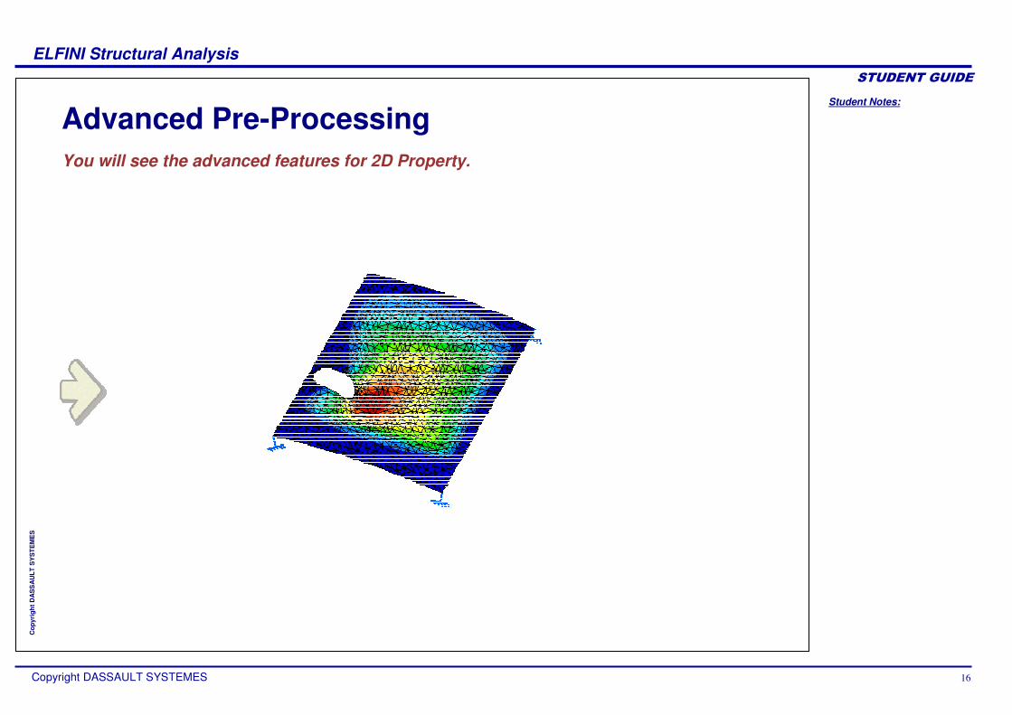
Advanced Pre-ProcessingYou will see the advanced features for 2D Property.
Student Notes:
ELFINI Structural Analysis������������
Copyright DASSAULT SYSTEMES 17
Cop
yrig
ht D
AS
SA
ULT
SY
STE
ME
S
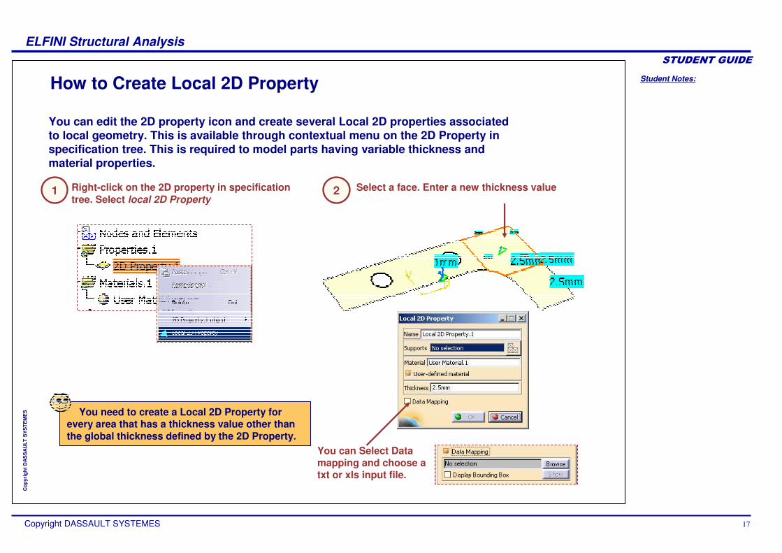
How to Create Local 2D Property
You can edit the 2D property icon and create several Local 2D properties associated to local geometry. This is available through contextual menu on the 2D Property in specification tree. This is required to model parts having variable thickness and material properties.
Right-click on the 2D property in specification tree. Select local 2D Property
Select a face. Enter a new thickness value
You can Select Data mapping and choose a txt or xls input file.
1 2
You need to create a Local 2D Property for every area that has a thickness value other than the global thickness defined by the 2D Property.

Student Notes:
ELFINI Structural Analysis������������
Copyright DASSAULT SYSTEMES 18
Cop
yrig
ht D
AS
SA
ULT
SY
STE
ME
S
Importing 2D Properties from External File
Choose Data Mapping, and Browse a xls file.
You can import 2D properties from an external file (.xls or .txt), and apply them locally or globally. There is no need for compatible grid and node identification.
Contextual menu on the 2D property icon. Select Create local 2D Property.
Compute Mesh Only.
At the point (-2,14,-7), there is a thickness value of 2*1mm
1
Select a face.2
3
4
Contextual menu on Properties, and Generate Image.
Choose Thickness fringe.
5
6
Student Notes:
ELFINI Structural Analysis������������
Copyright DASSAULT SYSTEMES 19
Cop
yrig
ht D
AS
SA
ULT
SY
STE
ME
S
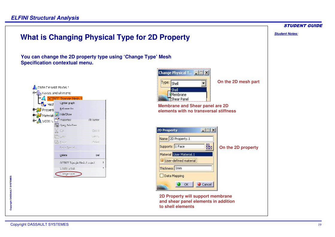
What is Changing Physical Type for 2D Property
2D Property will support membrane and shear panel elements in addition to shell elements
On the 2D property
On the 2D mesh part
Membrane and Shear panel are 2D elements with no transversal stiffness
You can change the 2D property type using ‘Change Type’ Mesh Specification contextual menu.

Student Notes:
ELFINI Structural Analysis������������
Copyright DASSAULT SYSTEMES 20
Cop
yrig
ht D
AS
SA
ULT
SY
STE
ME
S
What is Imported Composite Property
The orthotropic material is now available on 2D geometries
You can generate Composite FE model from the design by Plies/Zones.
There are two types of composites analysis :By zone for preliminary design By ply for detailed analysis
FE Composite properties are automatically generated from Design definition.
Full Support of FE simulation on composite models (pre-processing, solving, post-processing)
Type of analysis chosen ( by zone or by ply)
Optional tolerance for core sampling depth
Applied on 2D geometry

Student Notes:
ELFINI Structural Analysis������������
Copyright DASSAULT SYSTEMES 21
Cop
yrig
ht D
AS
SA
ULT
SY
STE
ME
S
How to Generate Image for Composite FE Model (1/2)
Click on ‘Imported Composite Property’icon.
1 2
3
Select the support and Analysis Type and launch Mesh Only computation.
Right-click on Properties in tree to open Image Generation dialogue box and Display Thickness fringe
You can generate the images related to Composite properties.
4 Double-click on the Image to get Image Edition Panel and change Lamina to 4

Student Notes:
ELFINI Structural Analysis������������
Copyright DASSAULT SYSTEMES 22
Cop
yrig
ht D
AS
SA
ULT
SY
STE
ME
S
How to Generate Image for Composite FE Model (2/2)
5 Click OK to view the image.
A new criterion ‘Sum’, which is used in the thickness fringe image to display the total thickness of all lamina of composite elements.
Student Notes:
ELFINI Structural Analysis������������
Copyright DASSAULT SYSTEMES 23
Cop
yrig
ht D
AS
SA
ULT
SY
STE
ME
S
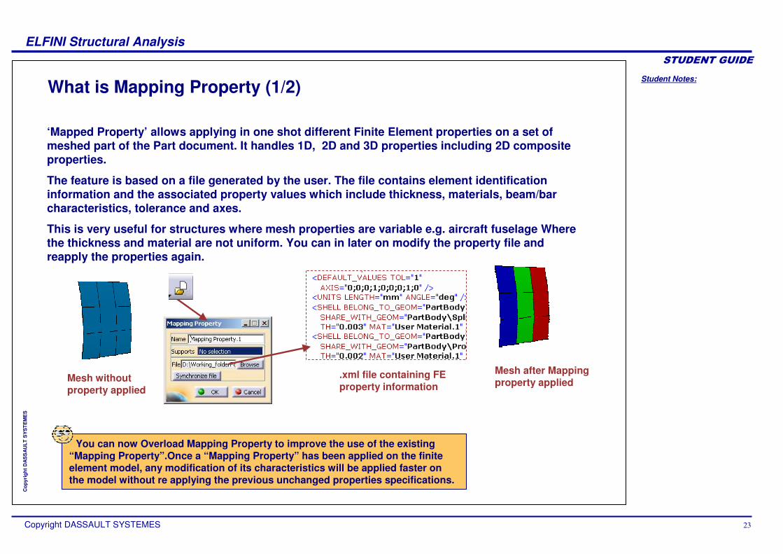
What is Mapping Property (1/2)
‘Mapped Property’ allows applying in one shot different Finite Element properties on a set of meshed part of the Part document. It handles 1D, 2D and 3D properties including 2D composite properties.
The feature is based on a file generated by the user. The file contains element identification information and the associated property values which include thickness, materials, beam/bar characteristics, tolerance and axes.
This is very useful for structures where mesh properties are variable e.g. aircraft fuselage Where the thickness and material are not uniform. You can in later on modify the property file and reapply the properties again.
Mesh without property applied
Mesh after Mapping property applied
.xml file containing FE property information
You can now Overload Mapping Property to improve the use of the existing “Mapping Property”.Once a “Mapping Property” has been applied on the finite element model, any modification of its characteristics will be applied faster on the model without re applying the previous unchanged properties specifications.

Student Notes:
ELFINI Structural Analysis������������
Copyright DASSAULT SYSTEMES 24
Cop
yrig
ht D
AS
SA
ULT
SY
STE
ME
S
What is Mapping Property (2/2)
There are two approaches for the element identification:
These two approaches can be mixed however the solution will not wholly be associative. Each time the property is updated (standard compute command) the whole file is parsed and properties applied to the elements
Element location is defined with the help of geometry surrounding the element
Here element location is defined using geometric co-ordinates.
Associative identification based on mesh part/group names and geometrical feature names
Spatial identification based on x, y, z coordinates of the element gravity center
Student Notes:
ELFINI Structural Analysis������������
Copyright DASSAULT SYSTEMES 25
Cop
yrig
ht D
AS
SA
ULT
SY
STE
ME
S
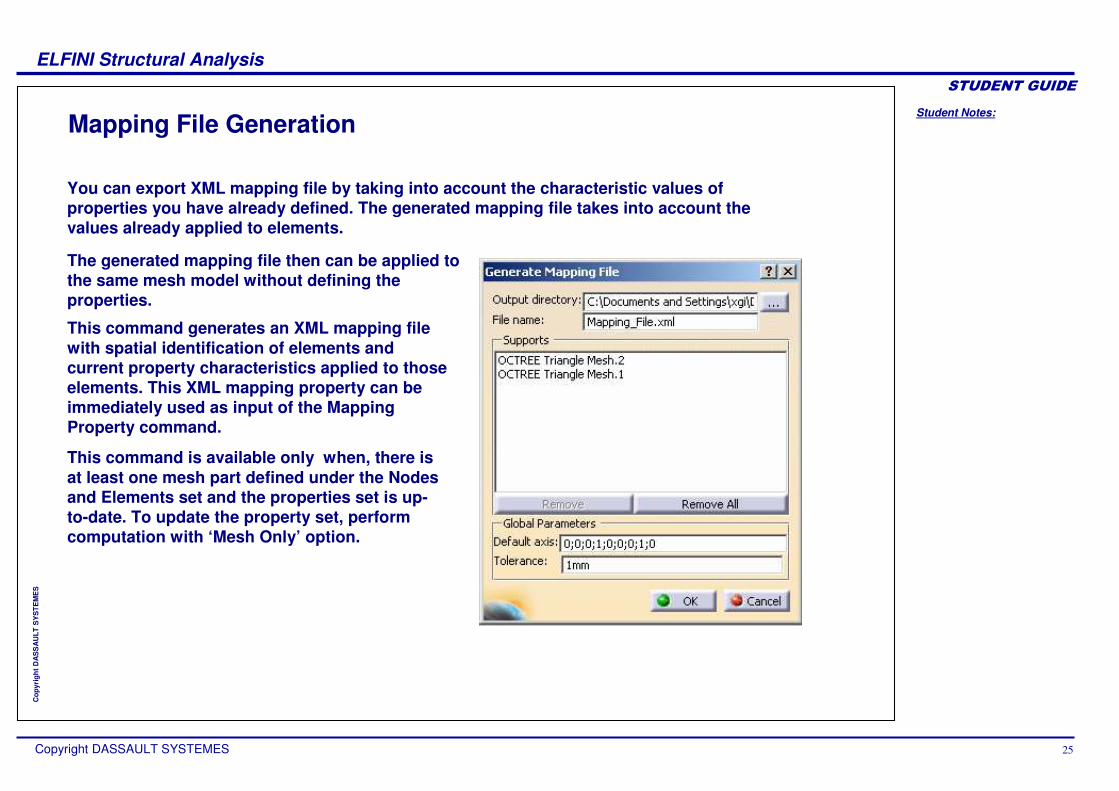
Mapping File Generation
You can export XML mapping file by taking into account the characteristic values of properties you have already defined. The generated mapping file takes into account the values already applied to elements.
The generated mapping file then can be applied to the same mesh model without defining the properties.
This command generates an XML mapping file with spatial identification of elements and current property characteristics applied to those elements. This XML mapping property can be immediately used as input of the Mapping Property command.
This command is available only when, there is at least one mesh part defined under the Nodes and Elements set and the properties set is up-to-date. To update the property set, perform computation with ‘Mesh Only’ option.

Student Notes:
ELFINI Structural Analysis������������
Copyright DASSAULT SYSTEMES 26
Cop
yrig
ht D
AS
SA
ULT
SY
STE
ME
S
How to Generate XML Mapping File
Right click the Properties node from the specification tree. Select ‘Generate mapping File’ option from the contextual menu.
1 Specify the Output directory and the file name to the xml file to be generated.
2
Select the mesh parts as support.3
Click OK.4

Student Notes:
ELFINI Structural Analysis������������
Copyright DASSAULT SYSTEMES 27
Cop
yrig
ht D
AS
SA
ULT
SY
STE
ME
S
Advanced Loads and Boundary ConditionsYou will see advanced features related to Loads and Boundary Conditions.

Student Notes:
ELFINI Structural Analysis������������
Copyright DASSAULT SYSTEMES 28
Cop
yrig
ht D
AS
SA
ULT
SY
STE
ME
S
What is Combined Loads/Masses
You can form linear combinations of existing loads/masses to reuse them in different computation cases. Loads/Masses can belong to different analysis cases.
Combination describes any linear combination, ‘αααα1ΑΑΑΑ1++++αααα2ΑΑΑΑ2+αααα3ΑΑΑΑ3+…’ where Ai are loads or masses and ααααi are the combination coefficients. Unit loads/masses can be defined once and then reused to define a lot of derived load/mass. Combining loads and masses will improve pre-processing tools.

Student Notes:
ELFINI Structural Analysis������������
Copyright DASSAULT SYSTEMES 29
Cop
yrig
ht D
AS
SA
ULT
SY
STE
ME
S
How to Create Combined Loads/Masses (1/2)
1
2 Select the required Load Set from pre-processing Load sets
Click on Combined Loads icon in Advanced Loads Toolbar
It is possible to select Loads using Search functionality.
You will learn how to form linear combination of existing loads/masses to reuse loads or masses in different computation cases.

Student Notes:
ELFINI Structural Analysis������������
Copyright DASSAULT SYSTEMES 30
Cop
yrig
ht D
AS
SA
ULT
SY
STE
ME
S
How to Create Combined Loads/Masses (2/2)
Select the Loads set in and click on Edit Coefficient in contextual menu
3
Enter the required coefficient and click OK
4
Similarly Edit Coefficient for other selected Load Sets and click OK
5
In similar way you can create Combined Mass.

Student Notes:
ELFINI Structural Analysis������������
Copyright DASSAULT SYSTEMES 31
Cop
yrig
ht D
AS
SA
ULT
SY
STE
ME
S
How to Use Periodicity Conditions
Click on Periodic Conditions icon.1 2
3
With Cyclic Symmetry conditions, you don’t have to analyze all your model, but only a symmetric sub-part of it. You can define infinite (translation with vector) or finite (rotation with vector and angle) cyclic symmetry.
Select the two faces of your sub-part.
These faces must be planarand identical, but their meshes can be different (incompatible mesh is taken into account).
Compute Mesh only.
A new mesh-part and a new property are created. New type of MPC elements (linear combination between the DOF of the nodes faces) are generated between the two faces.Periodicity Condition Symbol

Student Notes:
ELFINI Structural Analysis������������
Copyright DASSAULT SYSTEMES 32
Cop
yrig
ht D
AS
SA
ULT
SY
STE
ME
S
How to Use Bearing Loads (1/2)
Click on “Bearing Load” icon
Visualization of force distribution on each node after the computation
Select only a revolution surface-like support and enter a resultant effort
1
2
Bearing loads create contact-wise force only on revolution surfaces and simulate the action of a part on another one without modeling it. Eccentric loads are always perpendicular to the cylinder axis.
Student Notes:
ELFINI Structural Analysis������������
Copyright DASSAULT SYSTEMES 33
Cop
yrig
ht D
AS
SA
ULT
SY
STE
ME
S
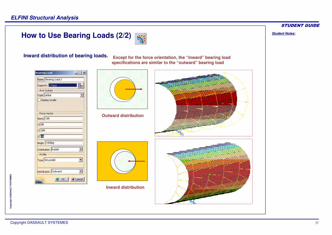
How to Use Bearing Loads (2/2)
Outward distribution
Inward distribution
Inward distribution of bearing loads. Except for the force orientation, the “inward” bearing load specifications are similar to the “outward” bearing load

Student Notes:
ELFINI Structural Analysis������������
Copyright DASSAULT SYSTEMES 34
Cop
yrig
ht D
AS
SA
ULT
SY
STE
ME
S
How to Use Thermo-mechanical Loads (1/2)
Click on Temperature field icon. Select the required support and temperature value1 2
You can apply a temperature field loading on your model, available on solids and surfaces of bodies. Data mapping is also allowed.
Check the Data mapping and browse the file
Click on Show button to display values3 Double-click the Environment in tree to set the initial temperature4
Student Notes:
ELFINI Structural Analysis������������
Copyright DASSAULT SYSTEMES 35
Cop
yrig
ht D
AS
SA
ULT
SY
STE
ME
S
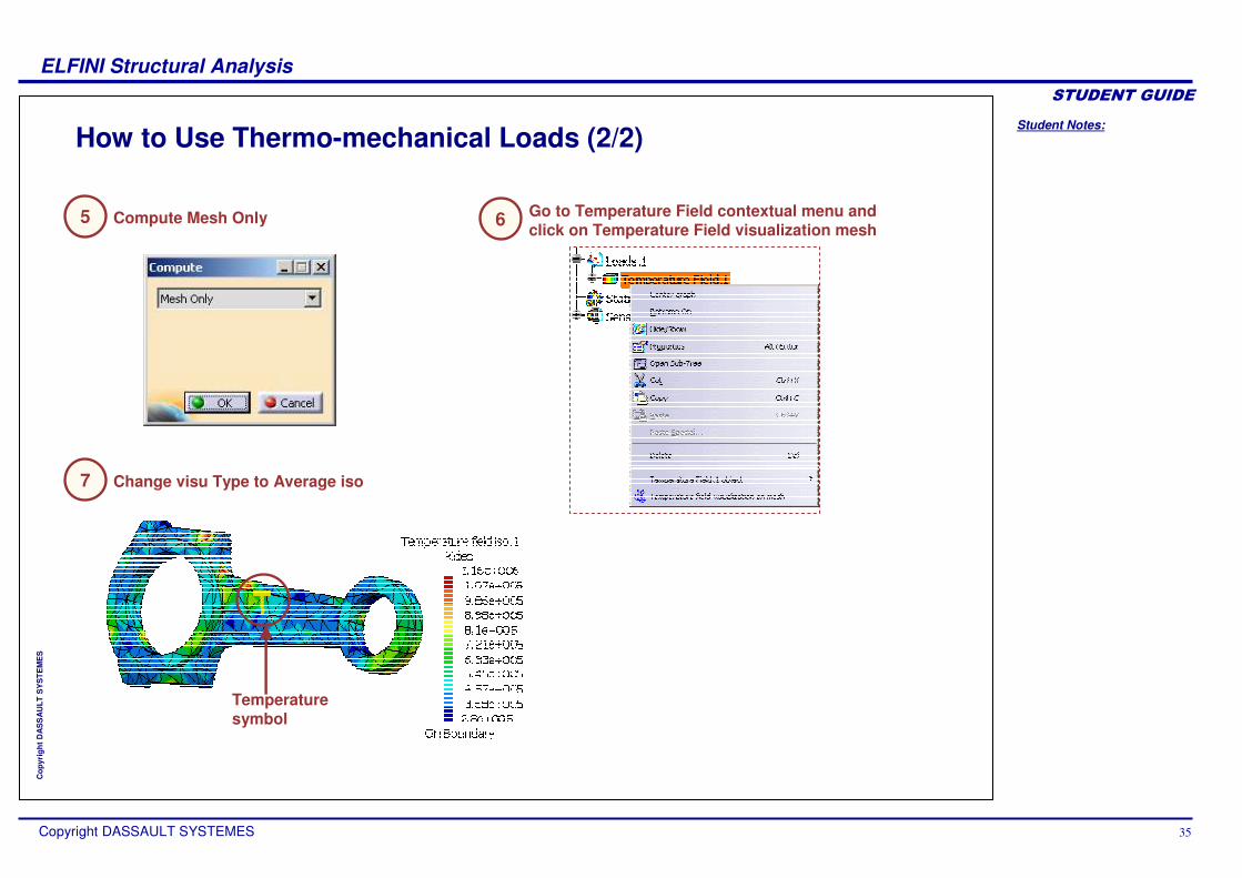
How to Use Thermo-mechanical Loads (2/2)
Go to Temperature Field contextual menu and click on Temperature Field visualization mesh6Compute Mesh Only5
Change visu Type to Average iso7
Temperature symbol
Student Notes:
ELFINI Structural Analysis������������
Copyright DASSAULT SYSTEMES 36
Cop
yrig
ht D
AS
SA
ULT
SY
STE
ME
S
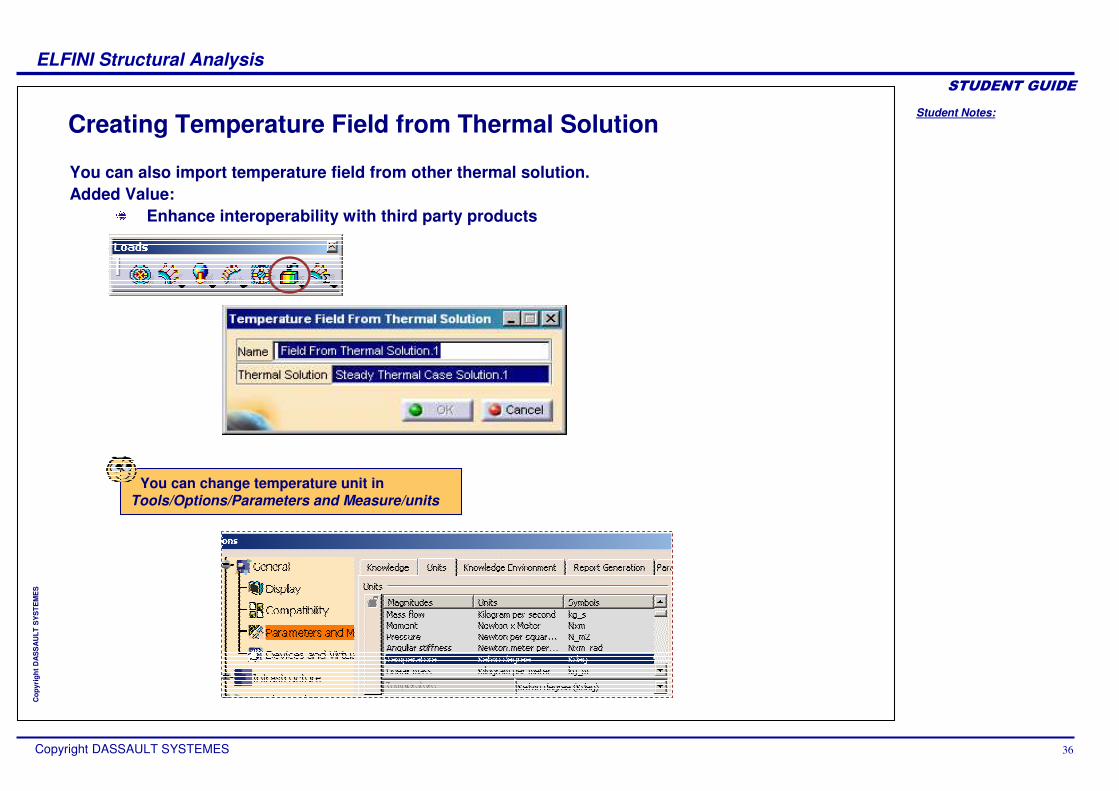
Creating Temperature Field from Thermal Solution
You can also import temperature field from other thermal solution.Added Value:
Enhance interoperability with third party products
You can change temperature unit in Tools/Options/Parameters and Measure/units

Student Notes:
ELFINI Structural Analysis������������
Copyright DASSAULT SYSTEMES 37
Cop
yrig
ht D
AS
SA
ULT
SY
STE
ME
S
Creating Self-balancing on Load set
Double-click on the Loadsicon in the tree.
Select the Self Balancingoption, and choose Yes.
1
2
Used with iso-static restraint, you can simulate free-body loading.
Result : load is “self-balancing”so as to have a null resultant at the centre of inertia.
Self-balancing is an attribute available on a load set meaning that the resultant at the center of inertia is null.

Student Notes:
ELFINI Structural Analysis������������
Copyright DASSAULT SYSTEMES 38
Cop
yrig
ht D
AS
SA
ULT
SY
STE
ME
S
How to Use Imported Forces and Moments (1/2)
Click on the Forces or Moments import icon.
Select support (surface, edge or point).
Click Browse, and select the import file. Click Show, and visualize the import file content
1 2
43
Imported Forces can be applied either on surfaces or virtual parts. For each point in the data file, the corresponding force is distributed on the three closest nodes of the selected support.
You can import forces or moments data with the standard data-mapping format (excel or text file). Complete data transfer is also possible thanks to Image export data.

Student Notes:
ELFINI Structural Analysis������������
Copyright DASSAULT SYSTEMES 39
Cop
yrig
ht D
AS
SA
ULT
SY
STE
ME
S
How to Use Imported Forces and Moments (2/2)
Perform analysis of a complete structure with coarse mesh and Export Nodal forces at the connection.
You can perform accurate analysis with Export/Import capabilities :
Import the forces on the connection surface of the single part.
Perform refined mesh on the critical part.
3
21

Student Notes:
ELFINI Structural Analysis������������
Copyright DASSAULT SYSTEMES 40
Cop
yrig
ht D
AS
SA
ULT
SY
STE
ME
S
What is Data Mapping
The file must be pre-defined like this
This data mapping is available for pressure, line loads, surface loads, volume loads, thermo-mechanical loads, thickness property, and forces/moments.
You can re-use data that is external from CATIA V5 (experimental data or data coming from in-house codes or procedures).
The selected external data file will be either a .txt file (columns separated using the Tab key) or a .xls file with a pre-defined format (pressure : four columns, the first three columns letting you specify X, Y and Z points coordinates in the global axis and the last one containing the amplification coefficient).
Different units
Student Notes:
ELFINI Structural Analysis������������
Copyright DASSAULT SYSTEMES 41
Cop
yrig
ht D
AS
SA
ULT
SY
STE
ME
S
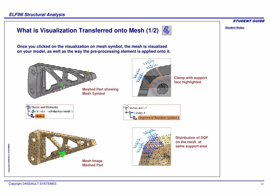
What is Visualization Transferred onto Mesh (1/2)
Once you clicked on the visualization on mesh symbol, the mesh is visualized on your model, as well as the way the pre-processing element is applied onto it.
Meshed Part showing Mesh Symbol
Mesh Image Meshed Part
Clamp with support face highlighted
Distribution of DOF on the mesh at same support area
Student Notes:
ELFINI Structural Analysis������������
Copyright DASSAULT SYSTEMES 42
Cop
yrig
ht D
AS
SA
ULT
SY
STE
ME
S
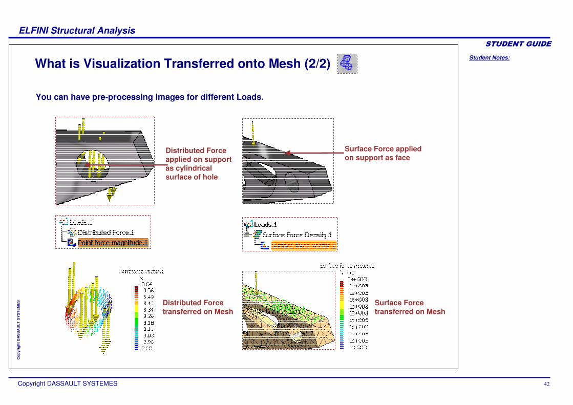
What is Visualization Transferred onto Mesh (2/2)
You can have pre-processing images for different Loads.
Distributed Force applied on support as cylindrical surface of hole
Distributed Force transferred on Mesh
Surface Force transferred on Mesh
Surface Force applied on support as face

Student Notes:
ELFINI Structural Analysis������������
Copyright DASSAULT SYSTEMES 43
Cop
yrig
ht D
AS
SA
ULT
SY
STE
ME
S
Visualizing Pre-processing Entities Transferred on Mesh
Create pre-processing elements.
Compute Mesh Only, which transfers pre-processing data onto the mesh (loads symbols have to appear yellow).
Click on “Restraint Visualization on Mesh”
Display contextual menu with a right mouse click on an existing pre-processing element (in the tree or directly on the model).
1
2
3
4
All pre-processing elements (restraints, loads, mass equipment) can be visualized on Mesh.

Student Notes:
ELFINI Structural Analysis������������
Copyright DASSAULT SYSTEMES 44
Cop
yrig
ht D
AS
SA
ULT
SY
STE
ME
S
How to Customize Visualization Transferred on Mesh
Double click on the visualization symbol, either on the tree or directly on the model.
Customize the visualization (choose the visualization type, customize symbol appearance)
Click OK.
1
2
3
Pre-processing visualization on mesh symbols can also be customized.

Student Notes:
ELFINI Structural Analysis������������
Copyright DASSAULT SYSTEMES 45
Cop
yrig
ht D
AS
SA
ULT
SY
STE
ME
S
What is FE Groups by Neighborhood
Point Group
Surface Group
Line Group
Provides associative capturing of mesh entitiesAllows pre-processing on non-associative meshes like:
Extruded mesh-partsImported orphan mesh

Student Notes:
ELFINI Structural Analysis������������
Copyright DASSAULT SYSTEMES 46
Cop
yrig
ht D
AS
SA
ULT
SY
STE
ME
S
How to Create Groups for Pre-processing
Click a Group icon.
Select the support (several surfaces for example).
Select any pre-processing conditions: restraint, load and choose the group as support.
1
2
3
You can create groups of geometrical entities so as to apply preprocessing conditions only on the associated nodes or elements. You will see how to create surface group and use it as support for applying distributed load.

Student Notes:
ELFINI Structural Analysis������������
Copyright DASSAULT SYSTEMES 47
Cop
yrig
ht D
AS
SA
ULT
SY
STE
ME
S
What is Import V4
Import V4 provides access to V4 Finite Element data for V5 analysis and analysis of assembly. Import is based on a result view only.
The following V4 entities will be transferred:FEM ModelMesh, Selections, Elements, Materials, Properties, axis systems, groupsPreprocessing Restraints, Loads, Non Structural-masses
All V4 transferred data will be created and stored in CATAnalysis file.
You can now import V4 Displacements as “orphan”results and can perform post-processing on V5 solutions without having to rebuild and compute equivalent cases.

Student Notes:
ELFINI Structural Analysis������������
Copyright DASSAULT SYSTEMES 48
Cop
yrig
ht D
AS
SA
ULT
SY
STE
ME
S
How to Import V4 Model
Open new Analysis document in Analysis & Simulation Workbench
Go to Links Manager Contextual Menu and click Import
Select CATIAV4 model file Expand the tree.
You will get FE entities imported
1 2
3 4

Student Notes:
ELFINI Structural Analysis������������
Copyright DASSAULT SYSTEMES 49
Cop
yrig
ht D
AS
SA
ULT
SY
STE
ME
S
Advanced Analysis Case ManagementEST license provides you various kinds of Analysis Cases in addition to static Analysis Case and a Frequency Analysis Case provided in GPS workbench.
Combined CaseStatic Constrained Modes CaseEnvelop CasePre-processing CaseMulti Loads CaseTransfer of Computed Loads/DisplacementsAssembled SolutionLocal Adaptivity SpecificationsMulti Analysis CaseHow to Use Frequency ShiftingBuckling Case

Student Notes:
ELFINI Structural Analysis������������
Copyright DASSAULT SYSTEMES 50
Cop
yrig
ht D
AS
SA
ULT
SY
STE
ME
S
Combined CaseYou will see how to create Combined Case from already existing Static cases.

Student Notes:
ELFINI Structural Analysis������������
Copyright DASSAULT SYSTEMES 51
Cop
yrig
ht D
AS
SA
ULT
SY
STE
ME
S
How to Create Combined Case
Create static cases. Insert a Combined Static Case.
1
Affect a coefficient :
CSCS = A*SCS.1 + B*SCS.2
Select the first Static Case Solution in the tree.
Add another Static Case : Contextual menu into the window and click Add.
34
2
You have the possibility to create linear combinations of static cases. Once you have computed several static cases, you can perform solutions combinations in Post-processing analysis.
You can also select the static solution having multi-load, assembled solutions, importedsolutions
Student Notes:
ELFINI Structural Analysis������������
Copyright DASSAULT SYSTEMES 52
Cop
yrig
ht D
AS
SA
ULT
SY
STE
ME
S
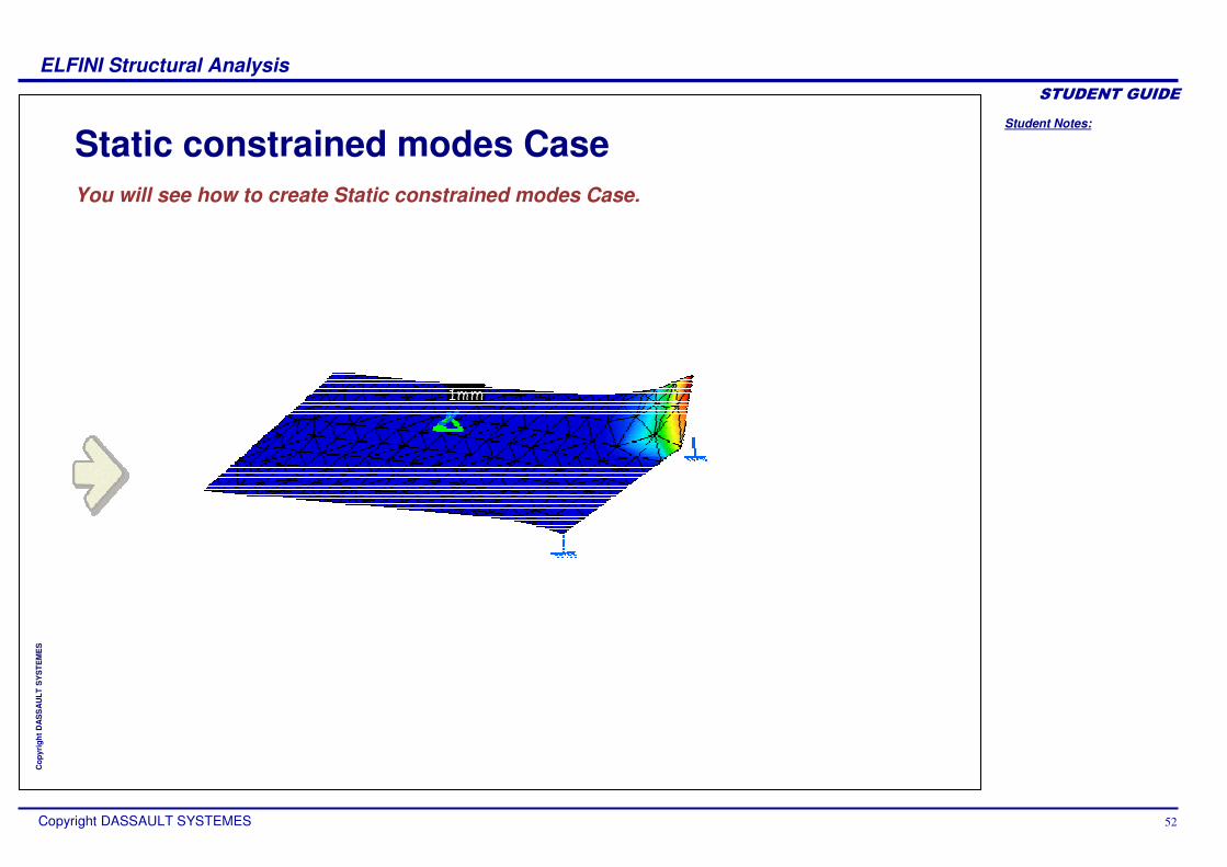
Static constrained modes CaseYou will see how to create Static constrained modes Case.

Student Notes:
ELFINI Structural Analysis������������
Copyright DASSAULT SYSTEMES 53
Cop
yrig
ht D
AS
SA
ULT
SY
STE
ME
S
How to Use Static Constrained Modes Case
Insert a Static Constrained modes Case.
Launch computation
Create a Restraint. For example a clamp on an edge
Display the results: deformed image or displacement image
Animate the deformed shape The animation shows each restrained nodes moving along its constrained DOF : X,Y and Z
2
3
1
4
5
You can generate a multi-occurrence solution made of static constrained modes cases.The output is a multi-occurrence solution made of static constrained modes : unitary imposed displacements are imposed on each DOF constrained by the restraint.The solution consists in (nb restrained nodes*nb restrained dof) structure displacements.
Clamp applied to edge

Student Notes:
ELFINI Structural Analysis������������
Copyright DASSAULT SYSTEMES 54
Cop
yrig
ht D
AS
SA
ULT
SY
STE
ME
S
Envelope CaseYou will study the envelope case which is used to find out most critical values among existing analysis cases.

Student Notes:
ELFINI Structural Analysis������������
Copyright DASSAULT SYSTEMES 55
Cop
yrig
ht D
AS
SA
ULT
SY
STE
ME
S
What is Envelop Case (1/2)
These extremes may be computed on any kind of values provided by the selected analysis sets.
The Envelop Case will contain:
An Envelop Set: It contains the definition of the support i.e. the entities on which the envelops will be computed and the selected analysis sets. Under this Envelop Set, you can create the Envelop Types which will contain information about what will be computed like physical type, values type, axis system definition, results definition.
An Envelop Solution: Solution will contain the result of the envelop computation. It will be updated using the standard ‘Compute’ command.
The results of an Envelop Solution will be available through images.
Envelop Set
Envelop Types
Images
There are two types of Analysis sets. This functionality enables you to search a selected number of most critical values such as minima, maxima or absolute value among several analysis sets.

Student Notes:
ELFINI Structural Analysis������������
Copyright DASSAULT SYSTEMES 56
Cop
yrig
ht D
AS
SA
ULT
SY
STE
ME
S
What is Envelop Case (2/2)
Two types of images will be available per envelop types.
Critical solutions imagesThe critical solutions will be displayed, by their index.
Values imagesThe most critical value will be displayed according to the chosen visualization mode
For both types of images, it will be possible to change the visualization type.
Student Notes:
ELFINI Structural Analysis������������
Copyright DASSAULT SYSTEMES 57
Cop
yrig
ht D
AS
SA
ULT
SY
STE
ME
S
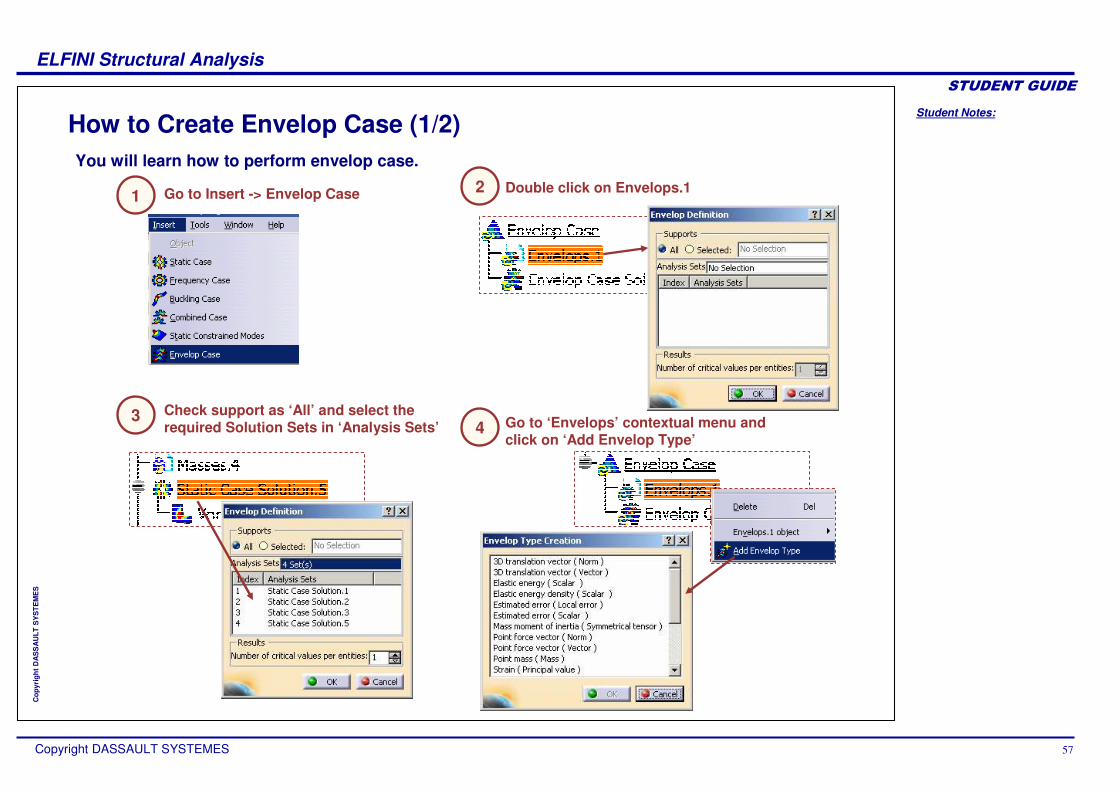
How to Create Envelop Case (1/2)
Go to Insert -> Envelop Case Double click on Envelops.1
Check support as ‘All’ and select the required Solution Sets in ‘Analysis Sets’ Go to ‘Envelops’ contextual menu and
click on ‘Add Envelop Type’
You will learn how to perform envelop case.
34
21

Student Notes:
ELFINI Structural Analysis������������
Copyright DASSAULT SYSTEMES 58
Cop
yrig
ht D
AS
SA
ULT
SY
STE
ME
S
How to Create Envelop Case (2/2)
Select required Envelop Type for which the case will be calculated
Compute the Envelop case
Go to ‘Envelop Case so;ution’ contextual menu, click on ‘Generate Image’
Select critical symbol image or values image and click ok to confirm.
7 8
65

Student Notes:
ELFINI Structural Analysis������������
Copyright DASSAULT SYSTEMES 59
Cop
yrig
ht D
AS
SA
ULT
SY
STE
ME
S
Pre-processing CaseYou will see the Pre-processing case which is used to organize pre-processing data for Finite Element model.

Student Notes:
ELFINI Structural Analysis������������
Copyright DASSAULT SYSTEMES 60
Cop
yrig
ht D
AS
SA
ULT
SY
STE
ME
S
What is Pre-processing Case
Pre-processing case is a new kind of analysis case which contains a lot of pre-processing data and no solution sets. It is useful tool to organize, store pre-processing data and reuse it in Solution-based cases.You can create several pre-processing cases in the same analysis model. You can define any type of Load Sets, Mass Sets or Restraint Sets.
It is possible to insert transferred Computed Loads in pre-processing sets.

Student Notes:
ELFINI Structural Analysis������������
Copyright DASSAULT SYSTEMES 61
Cop
yrig
ht D
AS
SA
ULT
SY
STE
ME
S
How to Create a Pre-processing Case
1
2 Create pre-processing set in Preprocessing Case contextual menu
Create required restraints, mass or load on generated pre-processing sets.
3
Go to Insert > Preprocessing case
The pre-processing case is used to store pre-processing data and reuse it in Solution-based cases.

Student Notes:
ELFINI Structural Analysis������������
Copyright DASSAULT SYSTEMES 62
Cop
yrig
ht D
AS
SA
ULT
SY
STE
ME
S
Multi Loads CaseYou will see how to use the Multi Loads case and reuse existing Loads and mass sets.

Student Notes:
ELFINI Structural Analysis������������
Copyright DASSAULT SYSTEMES 63
Cop
yrig
ht D
AS
SA
ULT
SY
STE
ME
S
What is Multi Loads Case (1/2)
Multi Loads Case is special Static Case containing:One Restraint SetOne Multiple-Load SetOne optional Mass Set
Multi Load Case uses Preprocessing case to store a large number of loads.
Multi Loads Set is a new type of Load Set. You can not create loads under a Multi Loads Case. You can only reference several Load Sets defined in any other cases. Thus, Multi Load Case Solution is multi-occurrence and each occurrence corresponds to a Load Set. It is necessary that all referenced Loads should belong to same Analysis Document.

Student Notes:
ELFINI Structural Analysis������������
Copyright DASSAULT SYSTEMES 64
Cop
yrig
ht D
AS
SA
ULT
SY
STE
ME
S
What is Multi Loads Case (2/2)
The multi Loads Set can reference any type of Load Set, including inertia loads and enforced displacements, V4 imported Loads. Inertia Loads computed within a Multi Loads Case are relative to the Multi Load Case additional Mass Set. Enforced Displacements computed in a Multi Load Case are relative to the Restraint entity specified in the Enforced Displacement definition panel (which may not be included in the Multiple-Load Case Restraint Set).
You can create images under the Solution using the standard ‘Generate Image’command. In the image edition panel, you can choose the Load Set. ‘Occurrence’ tab page displays the Load Set names.

Student Notes:
ELFINI Structural Analysis������������
Copyright DASSAULT SYSTEMES 65
Cop
yrig
ht D
AS
SA
ULT
SY
STE
ME
S
How to Use Multi Loads Case (1/2)
1 2 Check the Masses option, if required (optional) and press OK.
Double-click the Multi Loads in Static Case just created.
3
Go to Insert > ‘Static Case’ and check ‘Multi Loads’ option.
Select the required Loads from tree in the Multiple Load set.
4
It is possible to select Loads using Search functionality.
A Multi Loads Case is used to solve large number of loads on a single Finite Element model in one shot. Thus avoids the creation of separate analysis cases for each Load set. The Multi Loads case generally refers to Loads from preprocessing.

Student Notes:
ELFINI Structural Analysis������������
Copyright DASSAULT SYSTEMES 66
Cop
yrig
ht D
AS
SA
ULT
SY
STE
ME
S
How to Use Multi Loads Case (2/2)
5
8 View required images for different Load sets using occurrence Tab.
Apply Restraints and apply Masses (Masses are optional).
Click on Compute icon and click OK
7
Double-click the Static Case Solution, select Static Solution Parameters and press OK
6

Student Notes:
ELFINI Structural Analysis������������
Copyright DASSAULT SYSTEMES 67
Cop
yrig
ht D
AS
SA
ULT
SY
STE
ME
S
What is Transfer of Computed Loads/Displacements (1/2)
You can transfer Computed Loads/Displacements from one document to another document.Computed Loads (Forces) are applied loads evaluated by the solver at the Degrees Of Freedom (DOFs) of mesh nodes.Displacements are translations/rotations at DOFs of mesh nodes.
A displacements transfer is just the copy of solutions, between a source document and a target document. A loads transfer is a copy of computed loads, between a source document and a target document.
The Transfer of Computed Loads/Displacements from Source Document to Target Document will be done in two separate steps:
Export of Computed Loads/Displacements into .CATAnalysisExport file from Source Document.Import of .CATAnalysisExport file resulting from Source Document > Export to Target Document.
Exporting from Source Document to create .CATAnalysisExport file
Importing file to Target Document
Student Notes:
ELFINI Structural Analysis������������
Copyright DASSAULT SYSTEMES 68
Cop
yrig
ht D
AS
SA
ULT
SY
STE
ME
S
What is Transfer of Computed Loads/Displacements (2/2)
To export computed loads, an ‘Export Computed Loads’ command will be available on the following type of cases:
The .CATAnalysisExport file will contain the computed loads corresponding to the load sets used by the solution. Whatever the type of the transferred loads (Distributed Forces, Pressures, Force Densities) the file will contain the nodal force/moment vectors corresponding to these loads.
Static Case Multi Loads Case
Static Case SolutionsCombined Case SolutionV4 Imported SolutionsAssembled SolutionsMulti-Load Cases Solutions
To export displacements, an ‘Export Solution’ command will be available on the following type of solutions:
You can either transfer Computed Loads/Displacements:From Assembly to Sub-Analysis orBetween two analyses based on identical mesh

Student Notes:
ELFINI Structural Analysis������������
Copyright DASSAULT SYSTEMES 69
Cop
yrig
ht D
AS
SA
ULT
SY
STE
ME
S
What is Transfer of Computed Loads (1/2)
Transfer of Computed Loads from Assembly to Sub-Analysis level
Source Global Assembly Document
Target Sub-Analysis Document
Transfer of Computed Loads
For importing Computed Loads, you need to insert Pre-processing Case.

Student Notes:
ELFINI Structural Analysis������������
Copyright DASSAULT SYSTEMES 70
Cop
yrig
ht D
AS
SA
ULT
SY
STE
ME
S
What is Transfer of Computed Loads (2/2)
Transfer of Computed Loads between two analyses document based on identical mesh.
Source Analysis Document
Target Analysis Document
Transfer of Computed Loads
For importing Computed Loads, you need to insert Pre-processing Case.

Student Notes:
ELFINI Structural Analysis������������
Copyright DASSAULT SYSTEMES 71
Cop
yrig
ht D
AS
SA
ULT
SY
STE
ME
S
How to Transfer Computed Loads (1/2)
1 2 Browse the location where you want to store .CATAnalysisExport file
3
Go to Export > Solution in Static Case Solution contextual menu in Source Document and click ‘Computed Loads’.
Enter the File name and click on ‘Save’ Select the number of occurrences and sub-analysis, if required and click OK.
4
Sub Analysis option is available only In Assembly of Analysis. By default, the entire model will be exported.
You can use Transfer of Computed Loads to transfer forces either from Assembly Analysis to Sub-Analysis level or between two Analysis Documents having identical mesh.
Student Notes:
ELFINI Structural Analysis������������
Copyright DASSAULT SYSTEMES 72
Cop
yrig
ht D
AS
SA
ULT
SY
STE
ME
S
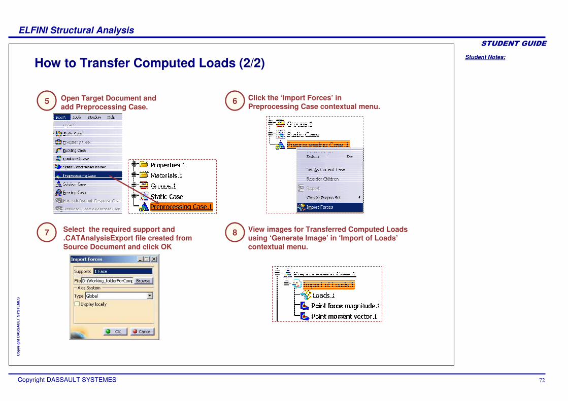
How to Transfer Computed Loads (2/2)
5
8 View images for Transferred Computed Loads using ‘Generate Image’ in ‘Import of Loads’contextual menu.
Open Target Document and add Preprocessing Case.
Select the required support and .CATAnalysisExport file created from Source Document and click OK
7
Click the ‘Import Forces’ in Preprocessing Case contextual menu.
6

Student Notes:
ELFINI Structural Analysis������������
Copyright DASSAULT SYSTEMES 73
Cop
yrig
ht D
AS
SA
ULT
SY
STE
ME
S
What is Transfer of Displacements (1/2)
Transfer of Displacement
Source Global Assembly Document
For importing Solution, you need to insert Solution Case. A Solution Case is case containing at least one Solution like Static Case, Frequency Case, transferred Solution
Transfer of Displacements from Assembly to Sub-Analysis level
Target
Sub-Analysis Document

Student Notes:
ELFINI Structural Analysis������������
Copyright DASSAULT SYSTEMES 74
Cop
yrig
ht D
AS
SA
ULT
SY
STE
ME
S
What is Transfer of Displacements (2/2)
Source Analysis Document
Transfer of Displacement
For importing Solution, you need to insert Solution Case. A Solution Case is case containing at least one Solution like Static Case, Frequency Case, transferred Solution
Transfer of Displacements between two analyses document based on identical mesh.
Target Analysis Document
Student Notes:
ELFINI Structural Analysis������������
Copyright DASSAULT SYSTEMES 75
Cop
yrig
ht D
AS
SA
ULT
SY
STE
ME
S
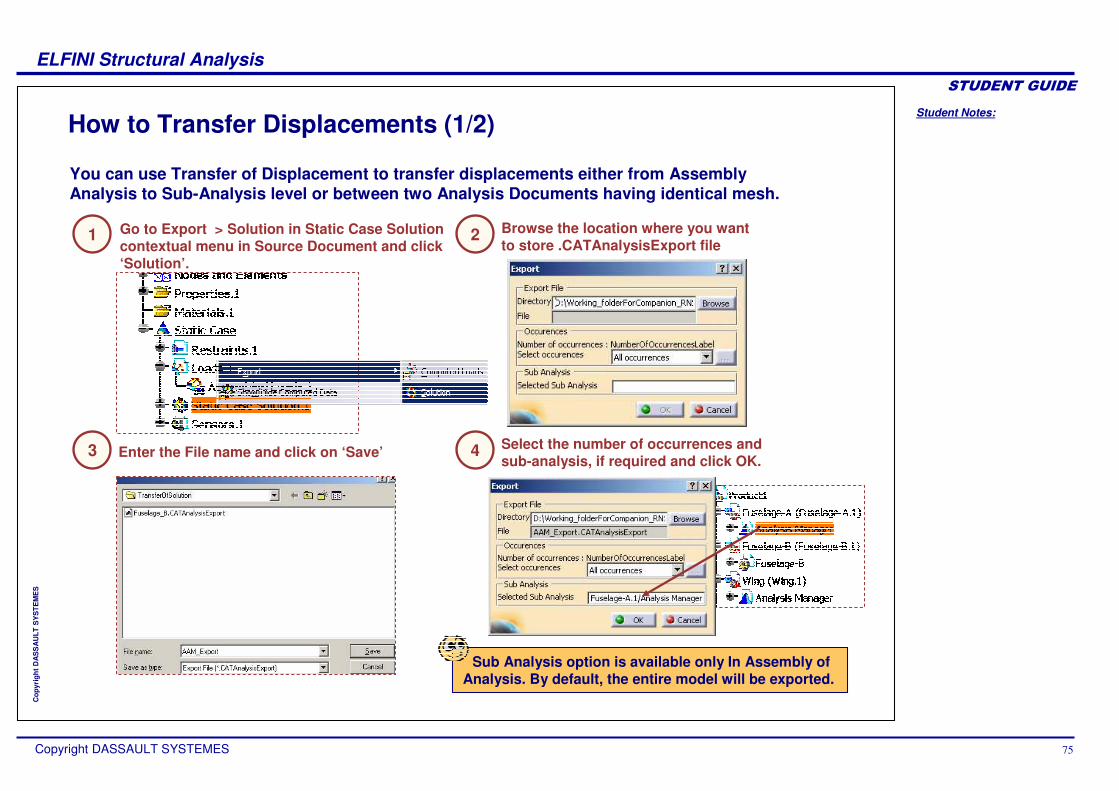
How to Transfer Displacements (1/2)
1 2 Browse the location where you want to store .CATAnalysisExport file
Enter the File name and click on ‘Save’3
Go to Export > Solution in Static Case Solution contextual menu in Source Document and click ‘Solution’.
Select the number of occurrences and sub-analysis, if required and click OK.
4
Sub Analysis option is available only In Assembly of Analysis. By default, the entire model will be exported.
You can use Transfer of Displacement to transfer displacements either from Assembly Analysis to Sub-Analysis level or between two Analysis Documents having identical mesh.
Student Notes:
ELFINI Structural Analysis������������
Copyright DASSAULT SYSTEMES 76
Cop
yrig
ht D
AS
SA
ULT
SY
STE
ME
S
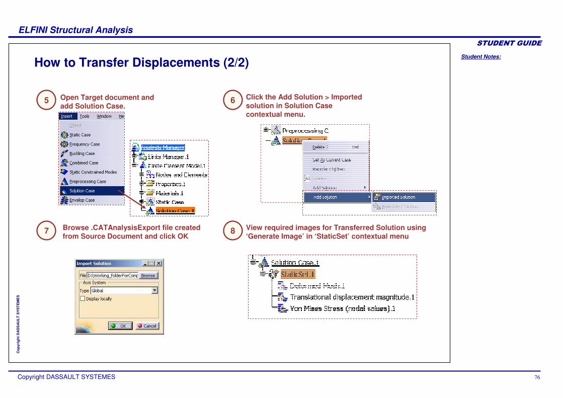
How to Transfer Displacements (2/2)
5
8 View required images for Transferred Solution using ‘Generate Image’ in ‘StaticSet’ contextual menu
Open Target document and add Solution Case.
Browse .CATAnalysisExport file created from Source Document and click OK
7
Click the Add Solution > Imported solution in Solution Case contextual menu.
6

Student Notes:
ELFINI Structural Analysis������������
Copyright DASSAULT SYSTEMES 77
Cop
yrig
ht D
AS
SA
ULT
SY
STE
ME
S
Assembled SolutionYou will learn the what is assembled solution and how to add the assembled solution.

Student Notes:
ELFINI Structural Analysis������������
Copyright DASSAULT SYSTEMES 78
Cop
yrig
ht D
AS
SA
ULT
SY
STE
ME
S
What is Assembled Solution
Assembled solution is the concatenation of several solutions computed in sub analyses.
Assembled solution is created in an assembled analysis. It is also called as displacement assembly. The aim of the assembled solution is to post-process all the components of an assembled model without carrying formal assembly analysis. In the assembled solution only component positioning is required (connections and preprocessing specifications are not required).
Assembled solutions are added to the solution case, which is a new type of analysis case gathering a collection of solutions. You can add several assembled solutions in the same solution case.

Student Notes:
ELFINI Structural Analysis������������
Copyright DASSAULT SYSTEMES 79
Cop
yrig
ht D
AS
SA
ULT
SY
STE
ME
S
How to add Assembled Solution
Create a solution case from Insert menu12
In the Assembled Solution dialog box, you can edit the name. 3
Select the required Analysis case solution from the specification tree. You can select multiple solutions.
4
Assembled Solution node gets added in the specification tree under the Solution Case.
5
Right-click on “Solution Case.1” and from the contextual menu select add Solution > Assembled Solution.

Student Notes:
ELFINI Structural Analysis������������
Copyright DASSAULT SYSTEMES 80
Cop
yrig
ht D
AS
SA
ULT
SY
STE
ME
S
Local Adaptivity SpecificationsYou will see how to create local mesh refinement based on adaptive mesh refinement.

Student Notes:
ELFINI Structural Analysis������������
Copyright DASSAULT SYSTEMES 81
Cop
yrig
ht D
AS
SA
ULT
SY
STE
ME
S
What is Local Adaptivity Specifications
The adaptivity method implemented is the H-method. At constant element order, the mesh is selectively refined (decrease element size) in such a way as to obtain a desired results accuracy. The mesh refining criteria are based on a technique called predictive error estimation, which consists of determining the distribution of a local error estimate field for a given Static Analysis Case.
As a result, the use of the adaptivity method makes it possible to reduce the memory costs and the time costs. The Adaptivity functionalities are only available with static analysis solution or a combined solution that references a static analysis solution.

Student Notes:
ELFINI Structural Analysis������������
Copyright DASSAULT SYSTEMES 82
Cop
yrig
ht D
AS
SA
ULT
SY
STE
ME
S
How to Create Local Adaptivity Specifications
Right-click Global Adaptivity.1 object in specification tree, select Local Adaptivity contextual menu
1 Select the required supports where you need to reduce the error.
2
You need to define Global adaptivity specifications before creating Local Adaptivity Specifications.
Local Adaptivity specifications allows you to reduce error in locally selected regions of mesh part. This local regions may be faces, edges or groups.
enter desired error value in Objective error.
3

Student Notes:
ELFINI Structural Analysis������������
Copyright DASSAULT SYSTEMES 83
Cop
yrig
ht D
AS
SA
ULT
SY
STE
ME
S
How to Create Multi Analysis Case
The newly created case is defined as current.
In the Insert menu, choose one of the three proposed analysis case types.
1Select an existing pre-processing element if necessary.2
You can insert any type of analysis case to an existing analysis document. Each pre-processing element can be defined either from scratch, or by replicating a pre-processing element of an existing analysis case.
Activate bottom button if you want the symbols of previous analysis cases to disappear from mesh.
2

Student Notes:
ELFINI Structural Analysis������������
Copyright DASSAULT SYSTEMES 84
Cop
yrig
ht D
AS
SA
ULT
SY
STE
ME
S
How to set Analysis Case as Active
Right click on an existing (inactive) analysis case, click on ‘Set as current Case’.
1
All the analysis cases you have created appear in the analysis tree. However, only one case is active at a time. The active case appears underlined in the features tree. You will see how to set required case as current case.

Student Notes:
ELFINI Structural Analysis������������
Copyright DASSAULT SYSTEMES 85
Cop
yrig
ht D
AS
SA
ULT
SY
STE
ME
S
How to Update Multi Analysis Case
Compute the analysis
Define two different analysis cases based on the same restraint set1
2
The factorization of the restraint set is performed only once
If you have several analysis cases in your analysis document that share a common restraint set, then the restraint is factorized only once.

Student Notes:
ELFINI Structural Analysis������������
Copyright DASSAULT SYSTEMES 86
Cop
yrig
ht D
AS
SA
ULT
SY
STE
ME
S
How to Use Frequency Shifting
Double-click on the Frequency solution icon in the tree
Enter the number of modes (here : 10)
Check the Shift option
Select the Lanczos method
Enter the frequency from which the computation will start
In this example, the first natural frequency after 1000 Hz is 3818.96 Hz
1
2
3
4
5
With Frequency Shifting, you can avoid heavy computation to look at natural frequencies in a given range, and so reduce computation time.

Student Notes:
ELFINI Structural Analysis������������
Copyright DASSAULT SYSTEMES 87
Cop
yrig
ht D
AS
SA
ULT
SY
STE
ME
S
Buckling CaseYou will see how to use Buckling Case.

Student Notes:
ELFINI Structural Analysis������������
Copyright DASSAULT SYSTEMES 88
Cop
yrig
ht D
AS
SA
ULT
SY
STE
ME
S
How to Use the Buckling Case (1/3)
Perform a Static Analysis, and compute its solution.
The new Buckling Analysis Case representation in the features tree contains two object sets : a Static Case Solution and a Buckling Case Solution. Select Static case solution on which the
buckling analysis is based on.
Insert a Buckling Case through the insert menu.1 2
3
Inserting a new Buckling Case allows you to perform the computation of buckling modes associated with a given Static Analysis Case
The Hide Existing Analysis Cases switch allows you to hide all symbols due to previous analysis cases.

Student Notes:
ELFINI Structural Analysis������������
Copyright DASSAULT SYSTEMES 89
Cop
yrig
ht D
AS
SA
ULT
SY
STE
ME
S
How to Use the Buckling Case (2/3)
The Buckling Solution Parameters box is displayed.
Double click on the Buckling Case Solution in the tree.
1
Adjust parameters (number of modes, dynamic parameters ).
2
Compute Buckling Case Solution.
3
You will see how to compute buckling modes.

Student Notes:
ELFINI Structural Analysis������������
Copyright DASSAULT SYSTEMES 90
Cop
yrig
ht D
AS
SA
ULT
SY
STE
ME
S
How to Use the Buckling Case (3/3)
The created images appear in tree under Buckling Case Solution.
Click on the Displacements image
Go to occurrences tab and choose mode and customize image.
Buckling factors represent the amplification coefficients to apply to the effort in static case for which the buckling modes appear.
Double click on image icon in tree to get Image edition dialogue box.1 2
3
Post-processing a Buckling Case is similar to post-processing a Frequency Case. In both cases you can create either a Displacements image or a Deformations image, and then select one of a given set of buckling modes.Each mode is associated with a coefficient, by which you multiply the loads in order to obtain the given buckling mode.
Only the first Buckling factor is generally used to verify if the load is critical.
You have to multiply the load value (a unit or the real loading) by the Buckling Factor to have the loading limit.

Student Notes:
ELFINI Structural Analysis������������
Copyright DASSAULT SYSTEMES 91
Cop
yrig
ht D
AS
SA
ULT
SY
STE
ME
S
Advanced Post-ProcessingIn this lesson, you will learn advanced post processing tools on top of the normal GPS and GAS post-processing tools. These tools allow you even more to customize the analysis results.
How to Customize ImageHow to Create Advanced ReportAccessing Advanced Post-processing ImagesContact PressureHow to Export Nodal ValuesHow to Generate Images for GroupsHow to Create an Image TemplateHow to Create Nodes and Elements ImagesLocal SensorsEST FunctionalitiesFrequently Asked QuestionsTo Sum Up

Student Notes:
ELFINI Structural Analysis������������
Copyright DASSAULT SYSTEMES 92
Cop
yrig
ht D
AS
SA
ULT
SY
STE
ME
S
How to Customize Image (1/5)
Double-click either on an image representation in the tree, or on the image itself.
Change Arrow Length with Size option. You can change the different visualization options
Select Symbol and click on Options button
3
2
1
With EST you get extra tools to customize your results images. You will see how to customize a displacements image.

Student Notes:
ELFINI Structural Analysis������������
Copyright DASSAULT SYSTEMES 93
Cop
yrig
ht D
AS
SA
ULT
SY
STE
ME
S
How to Customize Image (2/5)
Click on Options button
Select AVERAGE-ISO visualization mode (on Von-Mises image).
Activate ‘Display Element without value’
Change Shrink value6
7
5
4

Student Notes:
ELFINI Structural Analysis������������
Copyright DASSAULT SYSTEMES 94
Cop
yrig
ht D
AS
SA
ULT
SY
STE
ME
S
How to Customize Image (3/5)
Click on ‘More ’ to go to Filters
Change the position of computed value using position option
Images with C11 component selected
8
9
Select component whose values you want to map in component dropdown.
10
Images with C33 component selected

Student Notes:
ELFINI Structural Analysis������������
Copyright DASSAULT SYSTEMES 95
Cop
yrig
ht D
AS
SA
ULT
SY
STE
ME
S
How to Customize Image (4/5)
Go to Selections to select the entity you want to see.11
You can also select Groups in Available Groups.
Images with OCTREE Tetrahedron Mesh
Images with all Model

Student Notes:
ELFINI Structural Analysis������������
Copyright DASSAULT SYSTEMES 96
Cop
yrig
ht D
AS
SA
ULT
SY
STE
ME
S
How to Customize Image (5/5)
Create an image and then double-click on the color palette.
Click More.
Thresholds defined according to an histogram or linear distribution.
Option Histogram Distribution automatically adjusts color map to physical distribution.
3
21
Change the display format for a scientific or decimal display and Set significant digits
4
With EST you have extra tools for choosing the number of mapped colors on color palette.

Student Notes:
ELFINI Structural Analysis������������
Copyright DASSAULT SYSTEMES 97
Cop
yrig
ht D
AS
SA
ULT
SY
STE
ME
S
How to Create Advanced Report (1/5)
Advanced Report gives you access to all the data and results of your analysis, and allows you to build a fully customized report. You will see how to define the options for your Advanced Report .
Click on the “Advanced Reporting” icon
The Reporting Options box is displayed
Select an output directory
Enter a title for your report
Select the cases you want to include in your report
3
2
1
4
Static Case
Frequency Case
Buckling Case.
Imagine you are working on an analysis document containing three cases :
Click on OK to confirm the inputs of Advanced Report. The "Advanced Reporting Options" panel will be displayed.
5

Student Notes:
ELFINI Structural Analysis������������
Copyright DASSAULT SYSTEMES 98
Cop
yrig
ht D
AS
SA
ULT
SY
STE
ME
S
How to Create Advanced Report (2/5)
Advanced Reporting Options Panel.
The left part of the panel contains all the data and results available in the selected cases.
The right part of the panel will contain the structure of your report.
You can launch a browser to readily display the resulting report.

Student Notes:
ELFINI Structural Analysis������������
Copyright DASSAULT SYSTEMES 99
Cop
yrig
ht D
AS
SA
ULT
SY
STE
ME
S
How to Create Advanced Report (3/5)
Each element selected will appear in the right part of the panel.
Double click on the elements to extend the tree in left part of panel.
For each element you need in your report structure : Double click on it or select it and click the middle arrow
Proceed the same way to delete an element from your report structure.
Click OK when your report structure is completed.
Moving and zooming functions are available as in other CATIA windows (Middle mouse button to move + left button to zoom)
3
2
1
4
Build the structure of your Advanced Report using the data available in the left part of the options Panel.

Student Notes:
ELFINI Structural Analysis������������
Copyright DASSAULT SYSTEMES 100
Cop
yrig
ht D
AS
SA
ULT
SY
STE
ME
S
How to Create Advanced Report (4/5)
The report is constituted by a set of files (html, jpg, etc.) located in the specified directory.
Visualization of the generated report. You can visualize it while creating the report structure by launching the browser from the creation panel.

Student Notes:
ELFINI Structural Analysis������������
Copyright DASSAULT SYSTEMES 101
Cop
yrig
ht D
AS
SA
ULT
SY
STE
ME
S
How to Create Advanced Report (5/5)
A text document is also available, containing the same data than report without images. Its name is “ficel” without extension. You can open it with software like notepad. When you make a report, the data are added to it. You can also generate it by clicking the icon.

Student Notes:
ELFINI Structural Analysis������������
Copyright DASSAULT SYSTEMES 102
Cop
yrig
ht D
AS
SA
ULT
SY
STE
ME
S
Accessing Advanced Post-processing Images
Choose the Images to visualize.Contextual menu on Properties, Loads, Static or Frequency solutions in the tree. Click on Generate Image.
Image icons are created at the end of the tree.
21
Now, you have access to different advanced post-processing images on Properties, Loads, solutions.
PropertiesLoadsStatic SolutionsFrequency SolutionsCombined Case Solution

Student Notes:
ELFINI Structural Analysis������������
Copyright DASSAULT SYSTEMES 103
Cop
yrig
ht D
AS
SA
ULT
SY
STE
ME
S
Contact PressureYou will see how to create contact pressure image and how to customize the image.

Student Notes:
ELFINI Structural Analysis������������
Copyright DASSAULT SYSTEMES 104
Cop
yrig
ht D
AS
SA
ULT
SY
STE
ME
S
How to Create Contact Pressure Image (1/2)
Perform an assembly structural analysis with contact connections and compute it.
Right-click on “Static Case Solution.1”and select Generate Image.
Select Pressure Fringe or Pressure Vector
1
2
3
Contact Pressures are advanced visualization functions which allow the user to visualize on each part the pressure values exercised on contact surfaces.

Student Notes:
ELFINI Structural Analysis������������
Copyright DASSAULT SYSTEMES 105
Cop
yrig
ht D
AS
SA
ULT
SY
STE
ME
S
How to Create Contact Pressure Image (2/2)
Click on ‘Selections’ and select the entity you want to see.
Click on ‘Options’ in ‘Image Edition’ and check ‘Display Element Without Value’.
1 2
Customize the Contact Pressures Visualization to visualize only the contact pressures on each part by double-clicking on Pressure Fringe.
Different visualization with different Activated Groups

Student Notes:
ELFINI Structural Analysis������������
Copyright DASSAULT SYSTEMES 106
Cop
yrig
ht D
AS
SA
ULT
SY
STE
ME
S
How to Export Nodal Values
Select Export Data in Contextual menu on a Post-processing visualization (Von Mises Stress nodal value, for example).
Enter the output directory, a file name and choose between a text file or an excel type file.
21
If you edit the image and select a given selection, you will only export the nodal values of this selection (use Groups).
You can export nodal data from nodal values images (scalar, vector, tensor) with a text file or an .xls file.
Now you can export the data in 3dxml format.
X,Y,Z nodal coordinates in global axis system
Data in relation with the nodal value image
Select the Location axis system. You can select user co-ordinate system so that the exported values will be with respect to selected co-ordinate system.
3

Student Notes:
ELFINI Structural Analysis������������
Copyright DASSAULT SYSTEMES 107
Cop
yrig
ht D
AS
SA
ULT
SY
STE
ME
S
How to Generate Images for Groups
21
Remember to deactivate results images before selecting geometrical entities for groups.
Grouping elements allows you to generate images from a group of elements (points, lines, surfaces, bodies), or from a space allocation (box, sphere). So you have the possibility to focus post-processing analysis on critical areas.
Double click on a result image object to open the Image Edition window and click on Selection Tab
Double click on the already created Group be make it available in Activated Groups

Student Notes:
ELFINI Structural Analysis������������
Copyright DASSAULT SYSTEMES 108
Cop
yrig
ht D
AS
SA
ULT
SY
STE
ME
S
How to Create an Image Template
Customise a standard image (ex. Von Mises with Mid Layer)
Save it as New Template using its contextual menu and name it as ‘Von Mises Mid’
This image is now available Through Generate Image List
21
3
You can save your customised image as Image Template in order to store it.It will be available in the Generate Images listAllows to benefit from previous Image customization

Student Notes:
ELFINI Structural Analysis������������
Copyright DASSAULT SYSTEMES 109
Cop
yrig
ht D
AS
SA
ULT
SY
STE
ME
S
How to Create Nodes and Elements Images
Images are available for Nodes and Elements.
Display any available FEM image
In Nodes and Elements Contextual Menu, select generate Image
2
Generate the mesh. Launch a computation for mesh only
1
3
Image Names Meaning
Mesh
Elements text
Nodes text
Degrees of freedom
Local axis
Physical type fringe
Coordinate symbol node
Mesh
Elements numbers
Nodes numbers
Nodal symbol of fixed degrees of freedom
Symbol of local axis
Fringe image of the element physical type
Nodal coordinate symbol

Student Notes:
ELFINI Structural Analysis������������
Copyright DASSAULT SYSTEMES 110
Cop
yrig
ht D
AS
SA
ULT
SY
STE
ME
S
Local SensorsYou can get the output values at selected supports using Local sensors.

Student Notes:
ELFINI Structural Analysis������������
Copyright DASSAULT SYSTEMES 111
Cop
yrig
ht D
AS
SA
ULT
SY
STE
ME
S
How to Create Local Sensors
Create a local sensor using sensors contextual menu.
Double click on the created local sensor.
Enter Post Treatment : maximum, minimum or average and check to create parameters
2
1
3
Load sensor provides resulting force vector and moment vector: Fx, Fy, Fz, Mx, My, Mz. Inertia sensor provides mass and six inertia coefficients Ixx, Ixy, Ixz, Iyy, Iyz, Izz. These are available under Reaction Sensor.
You can generate a local sensor: displacement, Von-Misesextremum on a chosen geometry. It allows you to focus on specific area.

Student Notes:
ELFINI Structural Analysis������������
Copyright DASSAULT SYSTEMES 112
Cop
yrig
ht D
AS
SA
ULT
SY
STE
ME
S
EST Functionalities (1/3)
Buckling case.Inserting a new static case and a new frequency case (except for inserting a first static case and a first frequency case).Distributed mass visualization on mesh.Line mass density visualization on mesh.Surface mass density visualization on meshGenerate Image of masses objects.Basic analysis report of masses objects.Restraint visualization on mesh.Generate Image of restraint objects.Basic analysis report of restraint objects.Load visualization on mesh.Generate Image of load objects.Basic analysis report on load objects.Analysis Cases Solution Selection.Definition parameters of an Analysis Case. Generate Image of Static Analysis objects.Global analysis report of an Analysis Case.
These are the functionalities which run ONLY with EST :

Student Notes:
ELFINI Structural Analysis������������
Copyright DASSAULT SYSTEMES 113
Cop
yrig
ht D
AS
SA
ULT
SY
STE
ME
S
EST Functionalities (2/3)
Report on a deformed mesh.FEM Image editor.Selections tab in Image Edition for Von-Mises and Principal stresses.Image Iso Fringe Editor.Report on a Stress Von-Mises / Principal stresses feature.Selections tab in Symbol Editor.Image Axis System.Report on a translational displacement vector.Report on Estimated local error feature.Advanced reporting.Static constrained caseCombined caseImported composite propertyGroups functionalitiesPeriodicity conditionInertia on virtual partsBearing Load, Imported forces, Imported momentsForce densityCreating temperature field
These are the functionalities which run ONLY with EST :

Student Notes:
ELFINI Structural Analysis������������
Copyright DASSAULT SYSTEMES 114
Cop
yrig
ht D
AS
SA
ULT
SY
STE
ME
S
EST Functionalities (3/3)
These are the functionalities which run ONLY with EST :Advanced reportingImage layoutSimplified representationLocal 2D propertyLocal beam propertyLocal adaptivity

Student Notes:
ELFINI Structural Analysis������������
Copyright DASSAULT SYSTEMES 115
Cop
yrig
ht D
AS
SA
ULT
SY
STE
ME
S
Frequently Asked Questions
� Is the Contact Analysis no linear one?For the moment, contact analysis is linear (without friction effects).
� How to share analysis results?You can generate an html report, and users can specify its content thanks to Advanced Reporting function.
� How to launch a batch analysis?You can launch batch analysis with a macro written in VB Script.

Student Notes:
ELFINI Structural Analysis������������
Copyright DASSAULT SYSTEMES 116
Cop
yrig
ht D
AS
SA
ULT
SY
STE
ME
S
To Sum Up
Extra tools offered with advanced option EST :Advanced Pre-ProcessingAdvanced Analysis case managementAdvanced Post-Processing
In this course you have seen :