Embed Size (px)
Citation preview
1
Elevator application
1 Installation and wiring
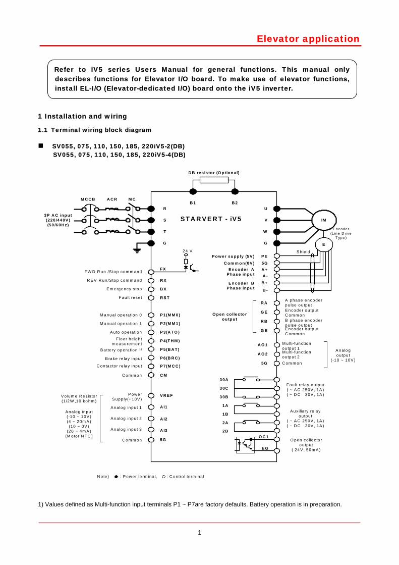
1.1 Terminal wiring block diagram
SV055, 075, 110, 150, 185, 220iV5-2(DB) SV055, 075, 110, 150, 185, 220iV5-4(DB)
P E
R
S
T
G
U
V
W
B 1 B 2
FX
R X
B X
R S T
P 1(M M 0 )
P 2(M M 1 )
P 3(A TO )
C M
V R E F
A I1
5G
IM3P A C inp u t(220/44 0V )(50 /6 0H z)
5GA +
R A
G E
R B
E
Encoder(L ine D rive
T ype)
G E
M CM C C B
M anu a l op era tion 0
M anu a l op era tion 1
A uto op era tion
C o m m on
V olum e R es is tor(1 /2W ,10 ko hm )
2 4 V
D B resis tor (O p tion al)
G
N ote) : P ow er te rm ina l, : C ontro l te rm ina l
S h ie ld
P 4(F H M )
P 5(B A T)
P 6(B R C )
P 7(M C C )
S TA R V E R T - iV 5
Floor he ig h tm easurem ent
B atte ry opera tio n 1)
B rake re lay input
C ontac tor re la y input
A I2
A I3
P ow e rS upp ly(+10V )
A na log inpu t(-10 ~ 10V )(4 ~ 2 0m A )(10 ~ 0V )
(20 ~ 4m A )(M otor N TC )
O p en co lle cto rou tp ut
A C R
A O 1
A O 2
5G
M ulti-fun ctionoutpu t 1M ulti-fun ctionoutpu t 2C om m on
A n alo go utput
(-10 ~ 10V )
3 0A
3 0C
3 0B
1A
1B
2B
2A
F au lt re lay ou tput( ~ A C 250V , 1A )( ~ D C 30V , 1A )
A ux ilia ry re layoutpu t
( ~ A C 250V , 1A )( ~ D C 30V , 1A )
O pen co lle c to ro u tpu t
( 24 V , 50 m A )
O C 1
E G
B +A -
B -
FW D R un /S top com m and
R E V R un/S top com m and
E m erge ncy sto p
F au lt rese t
A na log input 1
A na log input 2
A na log input 3
C o m m on
A p hase enco derp u lse o u tpu t
B p hase enco derp u lse o u tpu t
E n co der o u tpu tC om m on
E n co der o u tpu tC om m on
E n co de r AP has e inp u t
E n co de r BP has e inp u t
P o w er su pp ly (5 V )C om m o n(0 V )
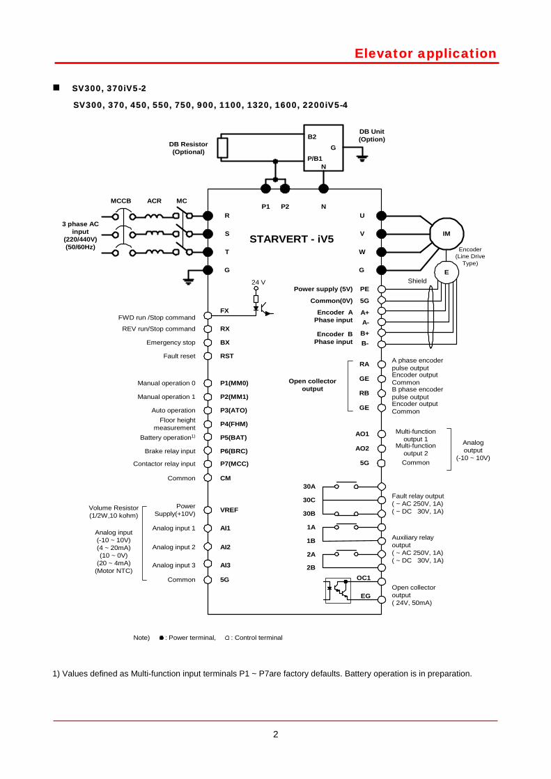
1) Values defined as Multi-function input terminals P1 ~ P7are factory defaults. Battery operation is in preparation.
Refer to iV5 series Users Manual for general functions. This manual onlydescribes functions for Elevator I/O board. To make use of elevator functions, install EL-I/O (Elevator-dedicated I/O) board onto the iV5 inverter.
2
Elevator application
SV300, 370iV5-2
SV300, 370, 450, 550, 750, 900, 1100, 1320, 1600, 2200iV5-4
PE
R
S
T
G
U
V
W
P1 N
FX
RX
BX
RST
P1(MM0)
P2(MM1)
P3(ATO)
CM
VREF
AI1
5G
IM
5G
A+
RA
GE
RB
E
GE
MCMCCB
24 V
G
Note) : Power terminal, : Control terminal
P4(FHM)
P5(BAT)
P6(BRC)
P7(MCC)
STARVERT - iV5
Floor heightmeasurement
AI2
AI3
ACRP2
B2
P/B1G
30A
30C
30B
1A
1B
2B
2A
OC1
EG
AO1
AO2
5G
Analogoutput
(-10 ~ 10V)
Multi-functionoutput 1
Multi-functionoutput 2Common
A-B+B-
N
Open collectoroutput( 24V, 50mA)
Fault relay output( ~ AC 250V, 1A)( ~ DC 30V, 1A)
Auxiliary relayoutput( ~ AC 250V, 1A)( ~ DC 30V, 1A)
A phase encoderpulse output
B phase encoderpulse output
Encoder outputCommon
Encoder outputCommon
Open collectoroutput
Encoder APhase input
Encoder BPhase input
Power supply (5V)
Common(0V)
Encoder(Line Drive
Type)
Shield
Manual operation 0
Manual operation 1
Auto operation
FWD run /Stop command
REV run/Stop command
Emergency stop
Fault reset
Common
Volume Resistor(1/2W,10 kohm)
Battery operation1)
Brake relay input
Contactor relay input
PowerSupply(+10V)
Analog input(-10 ~ 10V)(4 ~ 20mA)(10 ~ 0V)
(20 ~ 4mA)(Motor NTC)
Analog input 1
Analog input 2
Analog input 3
Common
3 phase ACinput
(220/440V)(50/60Hz)
DB Resistor(Optional)
DB Unit(Option)
1) Values defined as Multi-function input terminals P1 ~ P7are factory defaults. Battery operation is in preparation.
3
Elevator application1.2 Control terminal – Standard I/O Board and Elevator I/O board (EL-I/O)
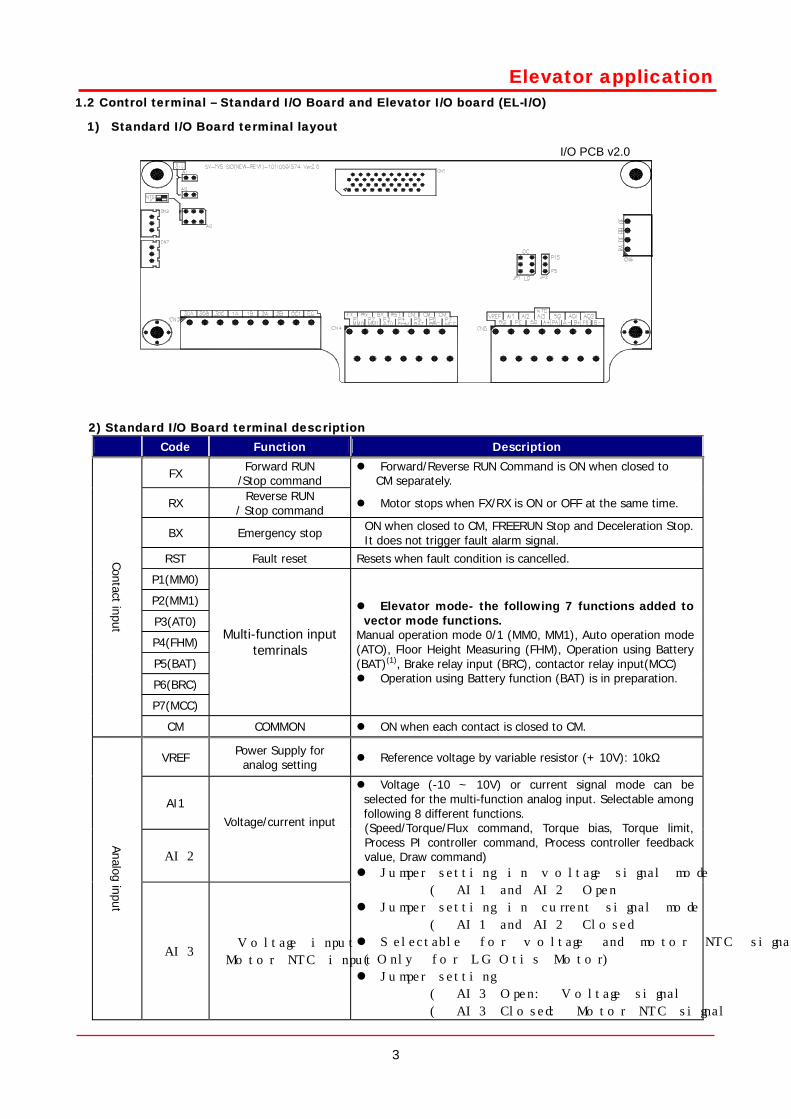
1) Standard I/O Board terminal layout
I/O PCB v2.0
2) Standard I/O Board terminal description Code Function Description
FX Forward RUN /Stop command
Forward/Reverse RUN Command is ON when closed to CM separately.
RX Reverse RUN / Stop command Motor stops when FX/RX is ON or OFF at the same time.
BX Emergency stop ON when closed to CM, FREERUN Stop and Deceleration Stop. It does not trigger fault alarm signal.
RST Fault reset Resets when fault condition is cancelled.
P1(MM0)
P2(MM1)
P3(AT0)
P4(FHM)
P5(BAT)
P6(BRC)
P7(MCC)
Multi-function input temrinals
Elevator mode- the following 7 functions added to vector mode functions.
Manual operation mode 0/1 (MM0, MM1), Auto operation mode (ATO), Floor Height Measuring (FHM), Operation using Battery (BAT)(1), Brake relay input (BRC), contactor relay input(MCC) Operation using Battery function (BAT) is in preparation.
Contact input
CM COMMON ON when each contact is closed to CM.
VREF Power Supply for analog setting Reference voltage by variable resistor (+ 10V): 10kΩ
AI1
AI2
Voltage/current input Analog input
AI3 Voltage input
Motor NTC input
Voltage (-10 ~ 10V) or current signal mode can be selected for the multi-function analog input. Selectable among following 8 different functions. (Speed/Torque/Flux command, Torque bias, Torque limit, Process PI controller command, Process controller feedback value, Draw command) Jumper setting in voltage signal mode
( AI1 and AI2 Open
Jumper setting in current signal mode
( AI1 and AI2 Closed
Selectable for voltage and motor NTC signal
(Only for LG Otis Motor)
Jumper setting
( AI3 Open: Voltage signal
( AI3 Closed: Motor NTC signal
4
Elevator application 5G COMMON COMMON for analog input
Code Function Description
PE +5V
5G
Power Supply for
Pulse Encoder 0V
A+
A- Encoder A phase
B+
B- Encoder B phase
A, B signal in Line Drive type Pulse Encoder
Jumper JP2 on the I/O PCB should be tied to P5,
Jumper JP1 to LD, respectively.
PE +15V
5G
Power Supply for
Pulse Encoder 0V
PA Encoder A phase
Puls
e E
ncoder In
put
PB Encoder B phase
A, B signal in Complementary or Open Collector
type Pulse Encoder.
Jumper JP2 on the I/O PCB should be tied to P15,
Jumper JP1 to OC, respectively.
RA A phase encoder pulse
output
GE Output Common
RB B phase encoder pulse
output
Encoder output
GE Output Common
Encoder A, B phase signal output – Open Collector Type
AO1 Analog output 1
AO2 Analog output 2
-10V ~ +10V Selectable among 31 different functions (Motor speed, Speed command1~2, Torque command1~2, Torque current, Flux command, Flux current, Output current, Output voltage, Motor temperature, DC Voltage.. )
Analog Output
5G COMMON COMMON for analog output
1A
1B
Multi-function Contact output 1
(a contact)
2A
2B
Multi-function Contact output 2
(a contact)
OC1
EG
Multi-function Open Collector output
Selectable among the following 14 functions Zero speed detect, Speed detect (Bi-directional), Speed detect (Uni-directional), Speed reach, Speed deviation, Torque detect, On torque limit, Motor overheat, Inverter overheat, On low voltage, Inverter running, Inverter regenerating, Inverter Ready, Timer output
30A Fault alarm, A contact
30B Fault alarm, B contact Activated when fault occurs. Not activated in case of emergency stop
Contact Output
30C COMMON COMMON for contact A and B
5
Elevator application
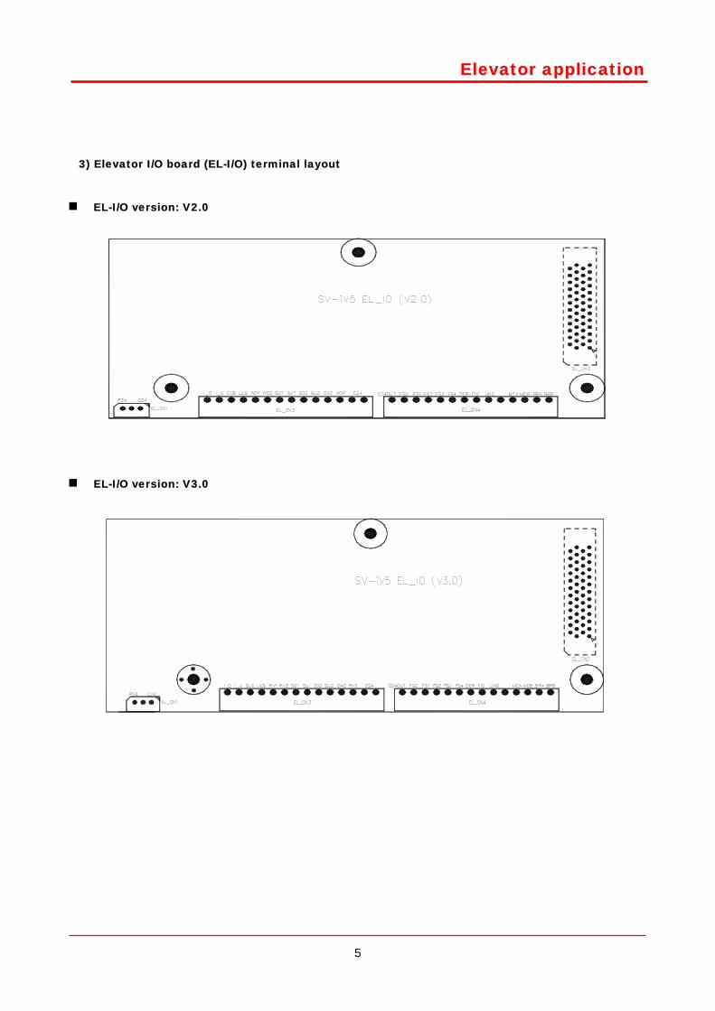
3) Elevator I/O board (EL-I/O) terminal layout
EL-I/O version: V2.0
EL-I/O version: V3.0
6
Elevator application
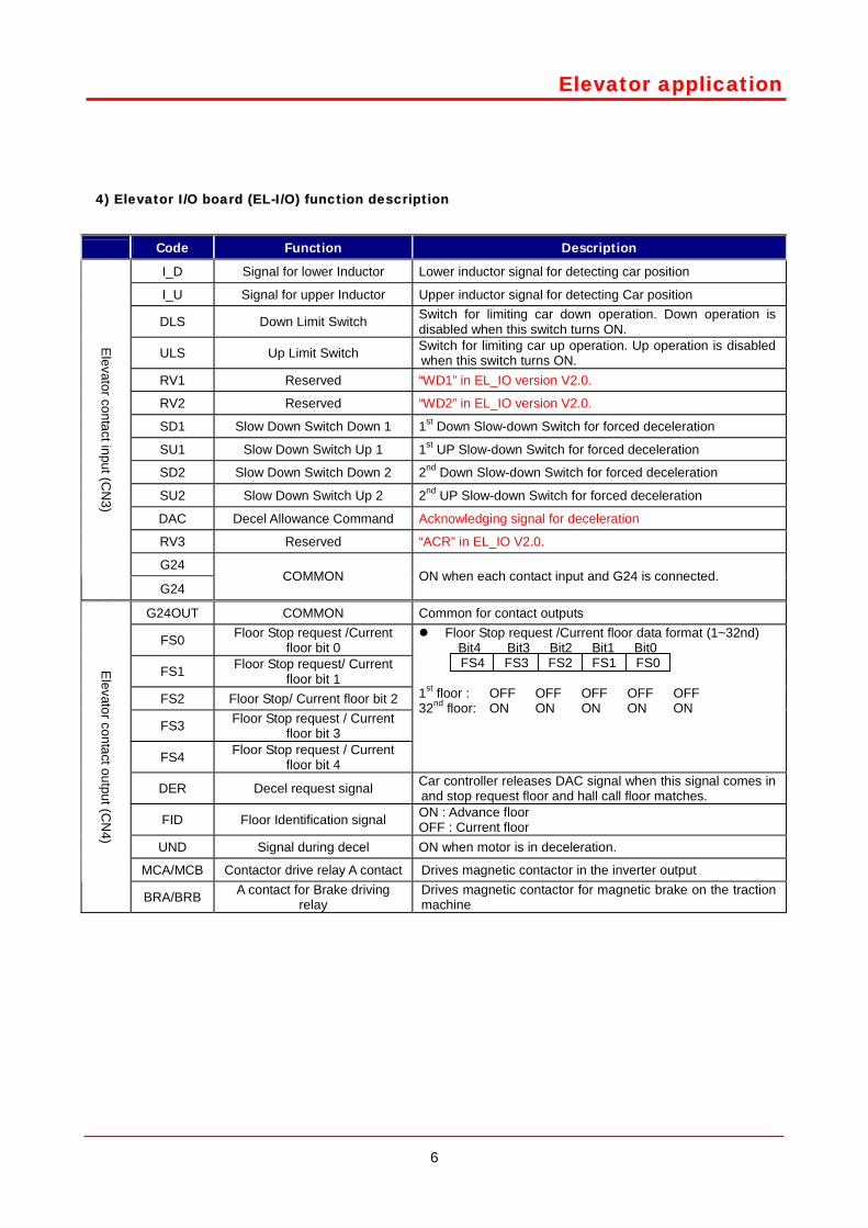
4) Elevator I/O board (EL-I/O) function description
Code Function Description
I_D Signal for lower Inductor Lower inductor signal for detecting car position
I_U Signal for upper Inductor Upper inductor signal for detecting Car position
DLS Down Limit Switch Switch for limiting car down operation. Down operation is disabled when this switch turns ON.
ULS Up Limit Switch Switch for limiting car up operation. Up operation is disabled when this switch turns ON.
RV1 Reserved “WD1” in EL_IO version V2.0.
RV2 Reserved “WD2” in EL_IO version V2.0.
SD1 Slow Down Switch Down 1 1st Down Slow-down Switch for forced deceleration
SU1 Slow Down Switch Up 1 1st UP Slow-down Switch for forced deceleration
SD2 Slow Down Switch Down 2 2nd Down Slow-down Switch for forced deceleration
SU2 Slow Down Switch Up 2 2nd UP Slow-down Switch for forced deceleration
DAC Decel Allowance Command Acknowledging signal for deceleration
RV3 Reserved “ACR” in EL_IO V2.0.
G24
Elevator contact input (C
N3)
G24 COMMON ON when each contact input and G24 is connected.
G24OUT COMMON Common for contact outputs
FS0 Floor Stop request /Current floor bit 0
FS1 Floor Stop request/ Current floor bit 1
FS2 Floor Stop/ Current floor bit 2
FS3 Floor Stop request / Current floor bit 3
FS4 Floor Stop request / Current floor bit 4
Floor Stop request /Current floor data format (1~32nd) Bit4 Bit3 Bit2 Bit1 Bit0
FS4 FS3 FS2 FS1 FS0 1st floor : OFF OFF OFF OFF OFF 32nd floor: ON ON ON ON ON
DER Decel request signal Car controller releases DAC signal when this signal comes in and stop request floor and hall call floor matches.
FID Floor Identification signal ON : Advance floor OFF : Current floor
UND Signal during decel ON when motor is in deceleration.
MCA/MCB Contactor drive relay A contact Drives magnetic contactor in the inverter output
Elevator contact output (C
N4)
BRA/BRB A contact for Brake driving relay
Drives magnetic contactor for magnetic brake on the traction machine

7
Elevator application 2 Getting started
2.1 Changing to Elevator mode
Set CON_02 (Application) to “Elevator” after I/O option card for Elevator (E/L-I/O Card) is installed. Then, LCD
window is displayed as shown below. Refer to Chapter 4, keypad for detailed key configuration.
1) Programming Elevator mode
Move to Application mode in CON group.
(CON_02 can set and displayed only when Elevator I/O card installed.)
Press the [PROG] key.
General Vector mode () will be displayed.
Set to Elevator mode using the [(Up)] key.
Press the [ENT] key to finish.
2.2 LCD display
E/L 32F STP
0.0m/m 0.0A
CONApplication
02 General Vect
CON Application
02 General Vect
CON Application
02 Elevator
CON Application
02 Elevator
8
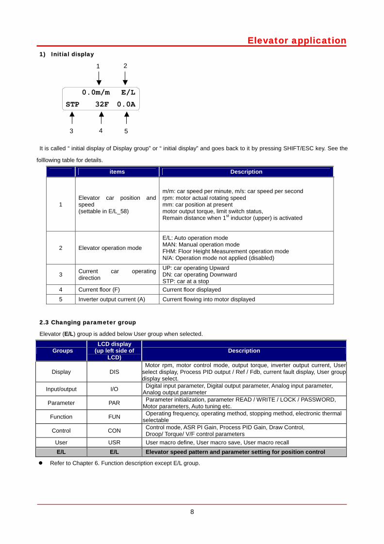
Elevator application1) Initial display
It is called “ initial display of Display group” or “ initial display” and goes back to it by pressing SHIFT/ESC key. See the
folllowing table for details.
items Description
1 Elevator car position and speed (settable in E/L_58)
m/m: car speed per minute, m/s: car speed per second rpm: motor actual rotating speed mm: car position at present motor output torque, limit switch status, Remain distance when 1st inductor (upper) is activated
2 Elevator operation mode
E/L: Auto operation mode MAN: Manual operation mode FHM: Floor Height Measurement operation mode N/A: Operation mode not applied (disabled)
3 Current car operating direction
UP: car operating Upward DN: car operating Downward STP: car at a stop
4 Current floor (F) Current floor displayed
5 Inverter output current (A) Current flowing into motor displayed
2.3 Changing parameter group
Elevator (E/L) group is added below User group when selected.
Groups LCD display
(up left side of LCD)
Description
Display DIS Motor rpm, motor control mode, output torque, inverter output current, User select display, Process PID output / Ref / Fdb, current fault display, User group display select.
Input/output I/O Digital input parameter, Digital output parameter, Analog input parameter, Analog output parameter
Parameter PAR Parameter initialization, parameter READ / WRITE / LOCK / PASSWORD, Motor parameters, Auto tuning etc.
Function FUN Operating frequency, operating method, stopping method, electronic thermal selectable
Control CON Control mode, ASR PI Gain, Process PID Gain, Draw Control, Droop/ Torque/ V/F control parameters
User USR User macro define, User macro save, User macro recall E/L E/L Elevator speed pattern and parameter setting for position control
Refer to Chapter 6. Function description except E/L group.
0.0m/m E/L
STP 32F 0.0A
4 5 3
1 2
9
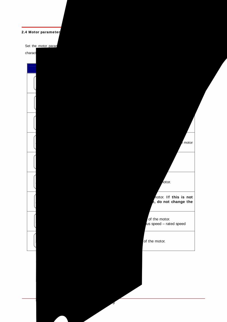
Elevator application2.4 Motor parameter input
Set the motor parameters as shown below before performing Auto-tuning operation to ensure the optimal control
characteristic of the traction motor.
Keypad display Description
Enter the motor capacity. Basically it is same as inverter capacity. If no match is found, select “User Define” in PAR_07 and enter the rating in PAR_08 directly. .
In case of selecting “User Define” in PAR_07, set the motor rating in this code directly.
Set the pulse numbers per revolution of pulse encoder coupled to the motor shaft.
Set the motor base speed. Note : it is not the rated speed written on the motor
nameplate.
Set the rated voltage of the motor. (Voltage value on the name plate)
Set the number of poles of the motor.
Set the efficiency of the motor. If this is not found on the nameplate, do not change the initial value.
Set the rated slip speed of the motor. Rated slip = synchronous speed – rated speed
Set the rated current of the motor.
PAR Moto r se lec t 07 kW
PAR Base Speed 17 rpm
PAR Po le number 19 [ ]
PAR Ra ted Vo l t 18 V
PAR Enc Pu lse 10 [ ] [ ] [ ] [ ]
PAR Rated -Cur r 22 A
PAR Rated -S l ip 21 rpm
PAR Efficiency 20 %
PAR UserMoto rSe l 08 kW
10
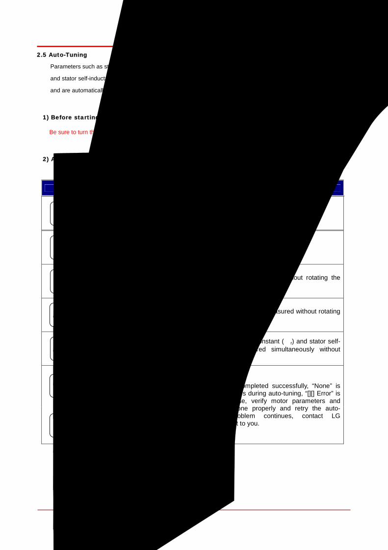
Elevator application2.5 Auto-Tuning
Parameters such as stator resistance (Rs), stator leakage inductance (sL ), flux current (IF), rotor time constant (τr)
and stator self-inductance (Ls) are indispensable for obtaining an excellent control performance in the vector control
and are automatically measured keeping the motor at standstill.
1) Before starting
Be sure to turn the machine brake off to hold the motor shaft tightly.
2) Auto-tuning procedure
Keypad display Description
Set the auto-tuning type to “Standstill”.
Auto-tuning starts if ALL1 is set.
Stator resistance (Rs) is measured without rotating the motor.
The leakage inductance (sL) is measured without rotating the motor.
Flux current (IF), rotor time constant (τr) and stator self-inductance (Ls) is measured simultaneously without rotating the motor.
When auto-tuning is completed successfully, “None” is displayed. If error occurs during auto-tuning, “[][] Error” is displayed. In this case, verify motor parameters and encoder setting is done properly and retry the auto-tuning. If the problem continues, contact LG representative nearest to you.
PAR Auto tuning 24 sL Tun ing
PAR Auto tuning 24 I f /Tr /Ls Tun ing
PAR Auto tuning 24 Rs Tun ing
PAR Auto tuning 24 ALL1
PAR AutoTuneType 23 StandSt i l l
PAR Auto tuning 24 [ ] [ ] E r ro r
PAR Auto tuning 24 None

11
Elevator application
2.6 Elevator parameter setting (in the case of 1500rpm, 120m/min, 32nd floor)
1) Enter total floor number
Enter the total number of floors including ground floor which car plate is installed.
2) Elevator rated speed input
3) Motor rated rpm input
Enters motor rpm when a car is running at E/L_03.
.
2.7 Operating mode and Multi-function relay output setting
Changing Elevator operating modes (High speed /Manual/FHM operation) are available using Multi-function input
terminals. The terminal functions should be defined based on the connection of MM0/P1, MM1/P2, ATO/P3,
FHM/P4 to select elevator operating modes.
E/L Floor Number02 32F
E/L Car Speed 03 120m/m
E/L Motor Speed 04 1500rpm
I/O P1 define 01 Manual Spd-L
I/O P2 define 02 Manual Spd-H
I/O P3 define 03 HighSpeedRun
I/O P4 define 04 FHM Run
12
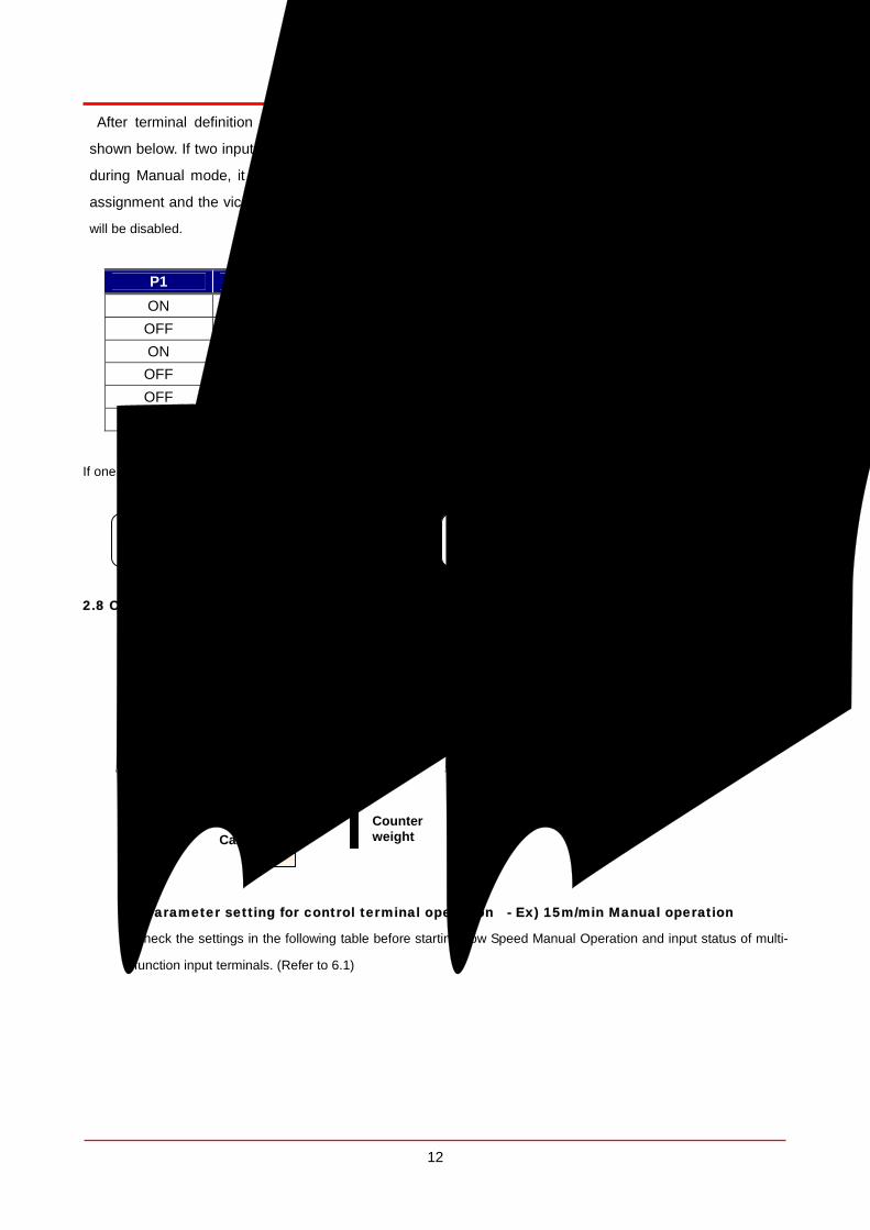
Elevator application After terminal definition is finished, operating modes are determined based on P1-P4 input status as
shown below. If two input modes are assigned at the same time, latter one is ignored. If FHM mode is input
during Manual mode, it is replaced by FHM mode. However, if terminal definition is done but not signal
assignment and the vice versa, LCD window will display ‘N/A’ and STOP/RESET LED (RED) will blink, operation
will be disabled.
P1 P2 P3 P4 Operation LCD displayON OFF OFF OFF Manual MAN OFF ON OFF OFF Manual MAN ON ON OFF OFF Manual MAN OFF OFF ON OFF Auto(High spd) E/L OFF OFF OFF ON FHM FHM OFF OFF OFF OFF NO MODE N/A
If one of AX1, AX2 is set to “RUN”, it can be used as Machine brake ON/OFF signal.
Or
2.8 Checking Encoder in Manual operation
1) UP direction ratating
Up direction means elevator car goes UP when FX input terminal is ON.
2) Parameter setting for control terminal operation - Ex) 15m/min Manual operation
Check the settings in the following table before starting Low Speed Manual Operation and input status of multi-
function input terminals. (Refer to 6.1)
Traction machine
Car Counter weight
UP direction
I/O AX1 define 41 Run
I/O AX2 define 42 Run
13
Elevator application
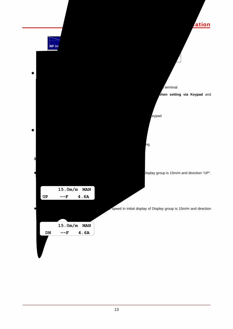
Description
MF input terminal Defining input
terminal functionInput value from operation
controller
MM0/P1 Manual Spd-L ON
MM1/P2 Manual Spd-H OFF
Moving to FUN group
① RUN/STOP command via control terminal
(“Err – CMDSRC” will apper when setting via Keypad and
operation unavailable.)
② Speed ref. selection via Keypad
Moving to E/L group
③ Operating speed setting
3) UP /DOWN direction operation
① Low Speed Manual operation
Press the [UP] button and check if motor speed in initial display of Display group is 15m/m and direction “UP”.
Floor height is displayed as “—F” before FHM operation.
Press the [DOWN] button and check if motor speed in initial display of Display group is 15m/m and direction
“DN”.
FUN Run/Stop Src
01 Terminal 1
FUN Spd Ref Sel
02 Keypad1
E/L Manual Spd1
22 15.0 m/m
15.0m/m MAN
UP --F 4.6A
15.0m/m MAN
DN --F 4.6A
14
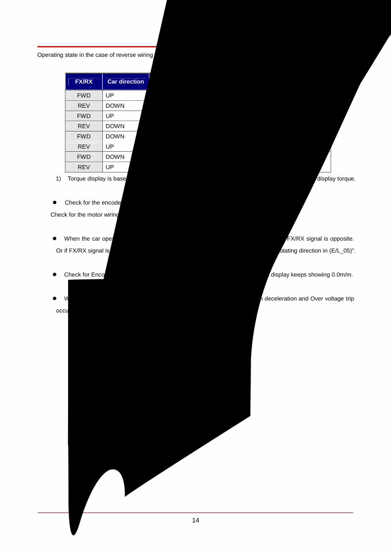
Elevator applicationOperating state in the case of reverse wiring of encoder and motor is as follows;
FX/RX Car direction Speed display Torque display 1) Operation status
FWD UP +15.0 m/m Over -10%
REV DOWN -15.0 m/m Over -10% Normal
FWD UP -4.5 ~ 10.5 m/m 150%
REV DOWN 4.5 ~ 10.5 m/m -150% Encoder wiring
reversed
FWD DOWN -4.5 ~ -10.5 m/m 150%
REV UP 4.5 ~ 10.5 m/m -150% Motor wiring
reversed
FWD DOWN +15.0 m/m Over +10%
REV UP -15.0 m/m Over +10%
Encoder / Motor wiring
reversed 1) Torque display is based on No-load low speed Manual operation. Set E/L_58 to “Trq Output” to display torque.
Check for the encoder wiring reversed. If so, correct the encoder wiring.
Check for the motor wiring reversed. If so, change the wiring of two phases (U,W).
When the car operating direction on the keypad display is reversed, check whether FX/RX signal is opposite.
Or if FX/RX signal is normally set but the car direction is opposite, change the motor rotating direction in (E/L_05)”.
Check for Encoder wiring and Multi-function input terminal setting when Speed display keeps showing 0.0m/m.
When vibration level is high during stop of manual operation due to sudden deceleration and Over voltage trip
occurs, change the setting of E/L_31 (ManZeroDec T) to 1.0 sec.
E/LManZeroDec T 31 1.0 sec

15
Elevator application2.9 FHM (Floor height measurement) operation
1) Check inductor signal and forced deceleration switch SD1 and SU1 are wired to elevator I/O board. If SU1 is
not properly installed, caution should be taken because the car may not stop at the highest level automatically
during FHM operaton. Move the car to Lowest floor and Highest floor by manual operation to check the input
of inductor and forced decel switch is properly installed. (Refer to 7.3 (46))
2) Move the car to the lowest floor with manual operation ON and stop the car at the position where upper
inductor is within the plate and down inductor is out of the plate as shown below.
3) Check E/L_02 (Floor Number) sett value matches total floors (Max. stop floor).
4) Change the operating mode to FHM operation by issuing ON signal to multi-function input terminal defined as
this operation. If inductor position is different from the above figure or SD1 is not activated, keypad will display
the message “NOTRDY” as shown below and STOP/RESET LED (Red) will be flickering. In this case, FHM
operation cannot be activated. Return to Manual operation mode and set the inductor position correctly and
check the forced deceleration switch and try FHM operation again.
5) Apply FX signal and FHM operating command in inverter control terminal and initiate FHM operation. Keep UP
operation command until car reaches the highest floor level. Car speed change is available if terminals defined
as MM0, MM1 are turned ON.
3) When car reaches the highest level, inverter automatically starts to decelerate and maintains the zero speed.
At this time, remove the FX signal and FHM operation is finished.
When UP/DOWN inductors signal is reversely connected to EL-I/O board, operation is stopped and fault
message will appear as shown below upon the car leaving lowest floor in early stage of FHM operation. In this
case, change the wiring of inductor signals. After this, return to Manual operation, move the car to the position
Car
Up/down inductor
Plate
1F(lowest flr)
E/L 0.0m/m FHM Err 1F NOTRDY

16
Elevator applicationsame as figure (page 15) and perform FHM operation again.
After FHM operation started and plate sensing signals from UP/Down inductors are not input at the same time,
the following message will appear with the operation stopped. In this case, adjust the inductor position. After this,
return to manual operation and move the car as directed in page 15 and restart FHM operation.
LCD display when FHM is completed. Current floor value becomes Highest floor (E/L_02).
After finishing FHM operation, each floor height can be checked in E/L_60 in mm.
① Press [PROG] key in E/L_60.
②Increase/decrease the floor No. by pressing [UP]/[DOWN]
Key.
③ Accumulated floor height is displayed as floor number is
increasing.
④ Escape the code using [MODE] or [ENT] key when
finished.
0.0m/m FHM
STP 32F 0.0A
DIS Faults 05 IND Reversed
DIS Faults 05 IND'TOR FAIL
E/LShow FlrPosi 60 1F
E/LPOSI 0mm 60 1F
E/LPOSI 3000mm
60 2F
E/LPOSI 45000mm 60 16F

17
Elevator application
When highest floor is reached but sensing number of UP/DOWN inductor is less than E/L_02 or measured floor
height data is incorrect, fault message will appear when removing FX signal.
① Plate sensing number does not match E/L_02
(Max stop-available floor).
② Measured floor data is wrong.
Check plate installation, noise interference in inductor signal and inductor malfunction to correct the error. After
clearing the cause, move the car to the lowest floor and retry FHM operation.
When FHM is failed, error message will appear in the initial display if not pressing [STOP/RESET] key while
fault message is output. Only pressing [MODE] key moves to initial display at fault message output ([SHIFT/ESC]
deactivated).
① Number of car plate sensing does not match E/L_02 (Max stop-available floor). FHM Run Fail
② When there is a certain floor far less than below floor or distance is too close. Flr Data Fail
When FHM is succeeded, each floor height and its checksum save into memory. If previous Checksum data and
new Checksum when power ON differ, the following error message will appear and FHM operation is required.
0.0m/m FHM Err 32F Fdata
0.0m/m FHM Err 32F Fcount
DIS Faults 05 FHM Run Fail
DIS Faults 05 Checksum Err
DIS Faults 05 Flr Data Fail

18
Elevator application
Forced decel switch (SD1, SU1) position measurement – Measure SD1 installation position based on lowest floor
level during FHM operation. Also, measure SU1 installation position based on highest floor level. Measured data
can be checked after setting DIS_01 ~ DIS_03 to either “SDSD1 Posi” or “SDSU1 Posi”..
2.10 High speed auto operation
High speed operation is ready to perform when FHM operation is finished successfully. However, FHM operation
is stopped when the upper inductor (IND_U) is not within a car plate so car does not begin operation when hall
call is input even if E/L_50 is set to “Inductor ON”(high speed operation active in normal condition). Therefore,
high speed auto operation should be performed after setting UP/DOWN indutors within the car plate by performing
manual operation.
Adjustment of Speed control gain and torque limit value
Adjust the gain for speed control and torque limit when large level error is generated at leveling to stop or car is not
stable during accel/decel operation. Gain value for speed control increases if ASR P Gain1 (CON_03) value is
increases, ASR I Gain1 (CON_04) value decreases.
Adjust the torque limit values for Pos Trq Lmt (CON_29), Neg Trq Lmt (CON_30), Reg Trq Lmt (CON_31) between
160% and 180% depending on the load condition.
Overload trip level and time setting
Set the OLT Level (I/O_60) between 150 and 170%, 10% less than torque limit value and OLT Time (I/O_61) to 60
sec.
Adjustment of operating condition at starting
Perform one floor, two floors, three floors and highest/lowest floor operation repeatedly to check car operating
condition at start, stop and during running at constant speed. Especially when sudden start shock occurs due to
static friction of traction machine, adjust the set value as shown below to get a better riding comfort.
Recommended adjusting range
(0.01 ~ 0.03m/s2) (0.3 ~ 0.8 sec) (0.2 ~ 0.4 sec)
DIS SDSD1 Posi 01 1200.0 mm
DIS SDSU1 Posi01 1200.0 mm
E/LHighSpdStart 50 Inductor ON
E/LStartUpAccel
52 0.01m/s2
E/LStartUpAccT
53 0.50 sec
E/LStartUp Wait
54 0.20 sec
19
Elevator application
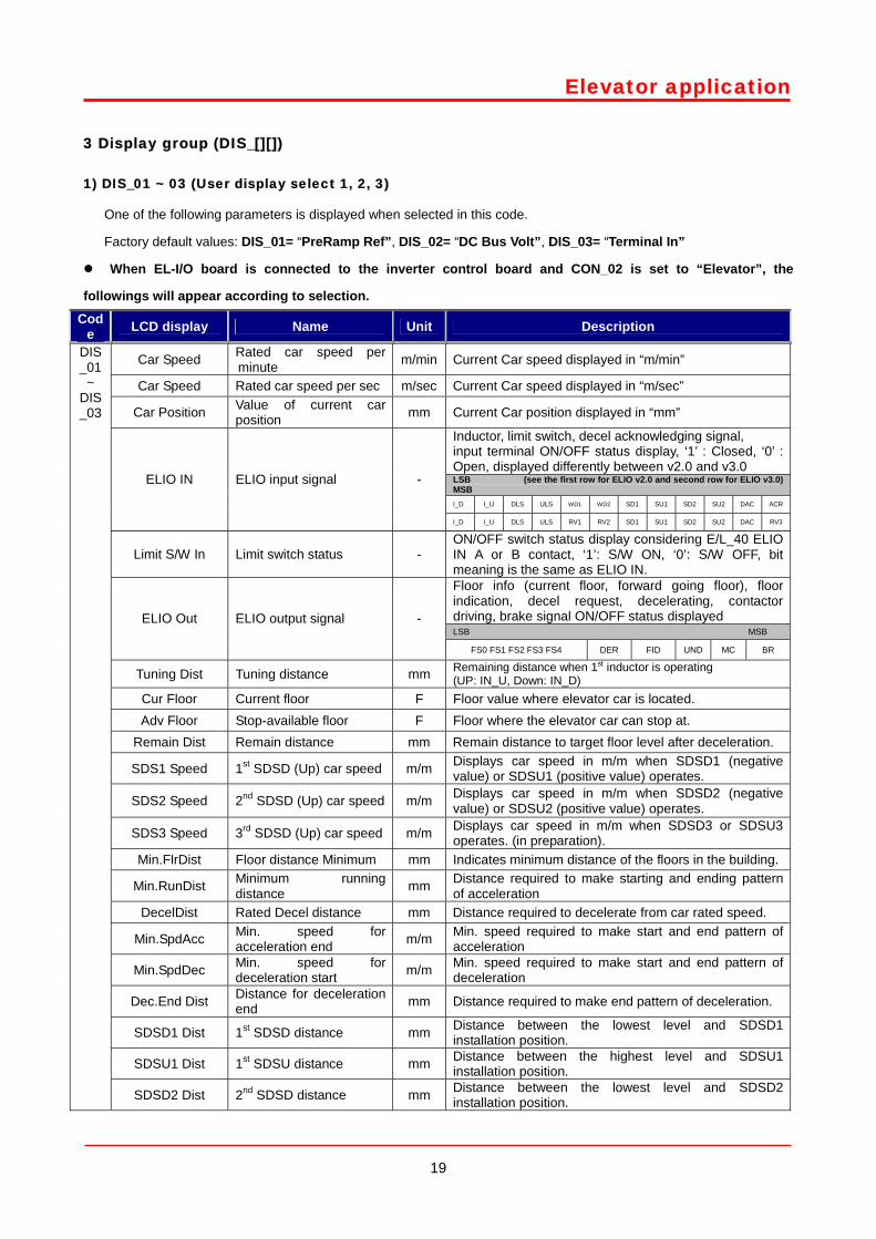
3 Display group (DIS_[][])
1) DIS_01 ~ 03 (User display select 1, 2, 3)
One of the following parameters is displayed when selected in this code.
Factory default values: DIS_01= “PreRamp Ref”, DIS_02= “DC Bus Volt”, DIS_03= “Terminal In”
When EL-I/O board is connected to the inverter control board and CON_02 is set to “Elevator”, the
followings will appear according to selection.
Code LCD display Name Unit Description
Car Speed Rated car speed per minute m/min Current Car speed displayed in “m/min”
Car Speed Rated car speed per sec m/sec Current Car speed displayed in “m/sec”
Car Position Value of current car position mm Current Car position displayed in “mm”
Inductor, limit switch, decel acknowledging signal, input terminal ON/OFF status display, ‘1’ : Closed, ‘0’ : Open, displayed differently between v2.0 and v3.0 LSB (see the first row for ELIO v2.0 and second row for ELIO v3.0) MSB I_D I_U DLS ULS WD1 WD2 SD1 SU1 SD2 SU2 DAC ACR
ELIO IN ELIO input signal -
I_D I_U DLS ULS RV1 RV2 SD1 SU1 SD2 SU2 DAC RV3
Limit S/W In Limit switch status - ON/OFF switch status display considering E/L_40 ELIO IN A or B contact, ‘1’: S/W ON, ‘0’: S/W OFF, bit meaning is the same as ELIO IN. Floor info (current floor, forward going floor), floor indication, decel request, decelerating, contactor driving, brake signal ON/OFF status displayed LSB MSB
ELIO Out ELIO output signal -
FS0 FS1 FS2 FS3 FS4 DER FID UND MC BR
Tuning Dist Tuning distance mm Remaining distance when 1st inductor is operating (UP: IN_U, Down: IN_D)
Cur Floor Current floor F Floor value where elevator car is located. Adv Floor Stop-available floor F Floor where the elevator car can stop at.
Remain Dist Remain distance mm Remain distance to target floor level after deceleration.
SDS1 Speed 1st SDSD (Up) car speed m/m Displays car speed in m/m when SDSD1 (negative value) or SDSU1 (positive value) operates.
SDS2 Speed 2nd SDSD (Up) car speed m/m Displays car speed in m/m when SDSD2 (negative value) or SDSU2 (positive value) operates.
SDS3 Speed 3rd SDSD (Up) car speed m/m Displays car speed in m/m when SDSD3 or SDSU3 operates. (in preparation).
Min.FlrDist Floor distance Minimum mm Indicates minimum distance of the floors in the building.
Min.RunDist Minimum running distance mm Distance required to make starting and ending pattern
of acceleration DecelDist Rated Decel distance mm Distance required to decelerate from car rated speed.
Min.SpdAcc Min. speed for acceleration end m/m Min. speed required to make start and end pattern of
acceleration
Min.SpdDec Min. speed for deceleration start m/m Min. speed required to make start and end pattern of
deceleration
Dec.End Dist Distance for deceleration end mm Distance required to make end pattern of deceleration.
SDSD1 Dist 1st SDSD distance mm Distance between the lowest level and SDSD1 installation position.
SDSU1 Dist 1st SDSU distance mm Distance between the highest level and SDSU1 installation position.
DIS_01 ~
DIS_03
SDSD2 Dist 2nd SDSD distance mm Distance between the lowest level and SDSD2 installation position.
20
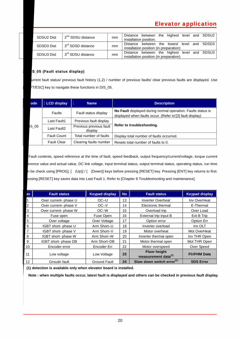
Elevator application
SDSU2 Dist 2nd SDSU distance mm Distance between the highest level and SDSU2 installation position.
SDSD3 Dist 3rd SDSD distance mm Distance between the lowest level and SDSD3 installation position (in preparation)
SDSU3 Dist 3rd SDSU distance mm Distance between the highest level and SDSU3 installation position (in preparation)
2) DIS_05 (Fault status display)
Current fault status/ previous fault history (1,2) / number of previous faults/ clear previous faults are displayed. Use
[SHIFT/ESC] key to navigate these functions in DIS_05.
Code LCD display Name Description
Faults Fault status display No Fault displayed during normal operation. Faults status is displayed when faults occur. (Refer to‘[3] fault display)
Last Fault1 Previous fault display
Last Fault2 Previous previous fault display
Refer to troubleshooting.
Fault Count Total number of faults Display total number of faults occurred.
DIS_05
Fault Clear Clearing faults number Resets total number of faults to 0.
Fault contents, speed reference at the time of fault, speed feedback, output frequency/current/voltage, torque current
reference value and actual value, DC link voltage, input terminal status, output terminal status, operating status, run time
can be check using [PROG], [(Up)] / [(Down)] keys before pressing [RESET] key. Pressing [ENT] key returns to first.
Pressing [RESET] key saves data into Last Fault 1. Refer to [Chapter 8 Troubleshooting and maintenance].
No Fault status Keypad display No Fault status Keypad display
1 Over current- phase U OC–U 13 Inverter Overheat Inv OverHeat 2 Over current- phase V OC–V 14 Electronic thermal E-Thermal 3 Over current- phase W OC–W 15 Overload trip Over Load 4 Fuse open Fuse Open 16 External trip input B Ext-B Trip 5 Over voltage Over Voltage 17 Option error Option Err 6 IGBT short- phase U Arm Short–U 18 Inverter overload Inv OLT 7 IGBT short- phase V Arm Short–V 19 Motor overheat Mot OverHeat 8 IGBT short- phase W Arm Short–W 20 Inverter thermal open Inv THR Open 9 IGBT short- phase DB Arm Short–DB 21 Motor thermal open Mot THR Open
10 Encoder error Encoder Err 22 Motor overspeed Over Speed
11 Low voltage Low Voltage 23 Floor height measurement data(1) Flr/FHM Data
12 Groudn fault Ground Fault 24 Slow down switch error(1) SDS Error (1) detection is available only when elevator board is installed.
Note : when multiple faults occur, latest fault is displayed and others can be checked in previous fault display.
21
Elevator application
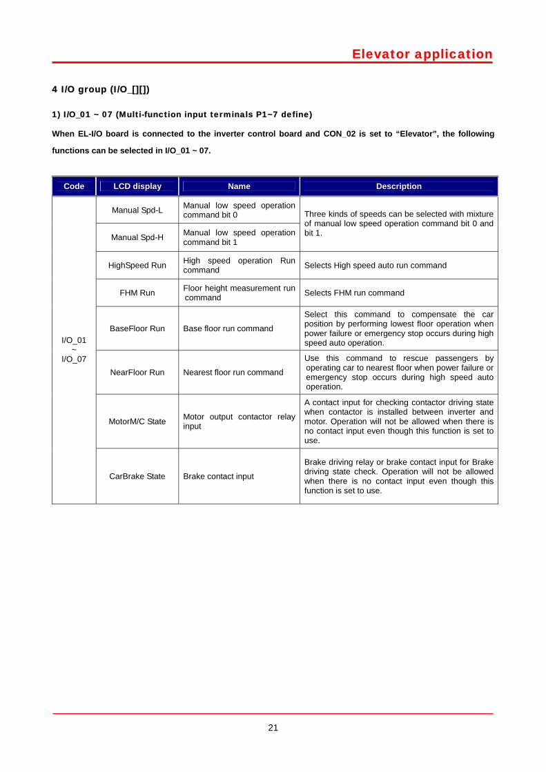
4 I/O group (I/O_[][])
1) I/O_01 ~ 07 (Multi-function input terminals P1~7 define)
When EL-I/O board is connected to the inverter control board and CON_02 is set to “Elevator”, the following
functions can be selected in I/O_01 ~ 07.
Code LCD display Name Description
Manual Spd-L Manual low speed operation command bit 0
Manual Spd-H Manual low speed operation command bit 1
Three kinds of speeds can be selected with mixture of manual low speed operation command bit 0 and bit 1.
HighSpeed Run High speed operation Run command Selects High speed auto run command
FHM Run Floor height measurement run command Selects FHM run command
BaseFloor Run Base floor run command
Select this command to compensate the car position by performing lowest floor operation when power failure or emergency stop occurs during high speed auto operation.
NearFloor Run Nearest floor run command
Use this command to rescue passengers by operating car to nearest floor when power failure or emergency stop occurs during high speed auto operation.
MotorM/C State Motor output contactor relay input
A contact input for checking contactor driving state when contactor is installed between inverter and motor. Operation will not be allowed when there is no contact input even though this function is set to use.
I/O_01 ~
I/O_07
CarBrake State Brake contact input
Brake driving relay or brake contact input for Brake driving state check. Operation will not be allowed when there is no contact input even though this function is set to use.
22
Elevator application
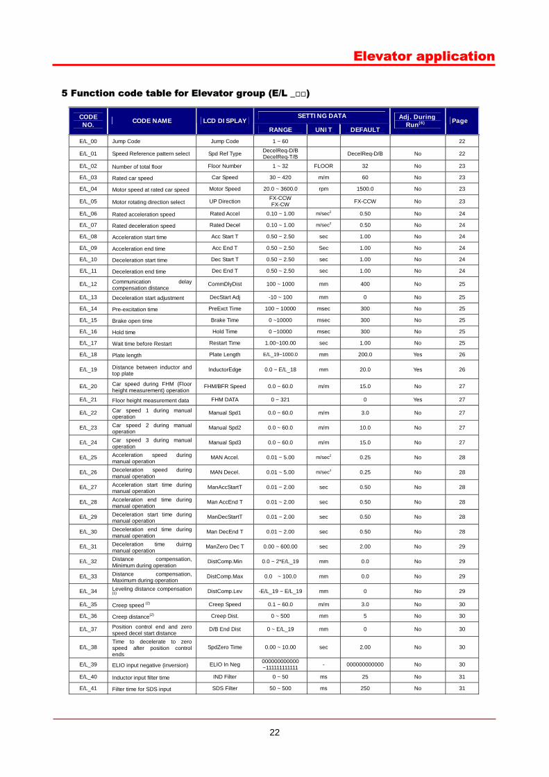
5 Function code table for Elevator group (E/L _)
SETTING DATA CODE NO. CODE NAME LCD DISPLAY
RANGE UNIT DEFAULT
Adj. During Run(6) Page
E/L_00 Jump Code Jump Code 1 ~ 60 22
E/L_01 Speed Reference pattern select Spd Ref Type DecelReq-D/B DecelReq-T/B DecelReq-D/B No 22
E/L_02 Number of total floor Floor Number 1 ~ 32 FLOOR 32 No 23
E/L_03 Rated car speed Car Speed 30 ~ 420 m/m 60 No 23
E/L_04 Motor speed at rated car speed Motor Speed 20.0 ~ 3600.0 rpm 1500.0 No 23
E/L_05 Motor rotating direction select UP Direction FX-CCW FX-CW FX-CCW No 23
E/L_06 Rated acceleration speed Rated Accel 0.10 ~ 1.00 m/sec2 0.50 No 24
E/L_07 Rated deceleration speed Rated Decel 0.10 ~ 1.00 m/sec2 0.50 No 24
E/L_08 Acceleration start time Acc Start T 0.50 ~ 2.50 sec 1.00 No 24
E/L_09 Acceleration end time Acc End T 0.50 ~ 2.50 Sec 1.00 No 24
E/L_10 Deceleration start time Dec Start T 0.50 ~ 2.50 sec 1.00 No 24
E/L_11 Deceleration end time Dec End T 0.50 ~ 2.50 sec 1.00 No 24
E/L_12 Communication delay compensation distance
CommDlyDist 100 ~ 1000 mm 400 No 25
E/L_13 Deceleration start adjustment DecStart Adj -10 ~ 100 mm 0 No 25
E/L_14 Pre-excitation time PreExct Time 100 ~ 10000 msec 300 No 25
E/L_15 Brake open time Brake Time 0 ~10000 msec 300 No 25
E/L_16 Hold time Hold Time 0 ~10000 msec 300 No 25
E/L_17 Wait time before Restart Restart Time 1.00~100.00 sec 1.00 No 25
E/L_18 Plate length Plate Length E/L_19~1000.0 mm 200.0 Yes 26
E/L_19 Distance between inductor and top plate
InductorEdge 0.0 ~ E/L_18 mm 20.0 Yes 26
E/L_20 Car speed during FHM (Floor height measurement) operation
FHM/BFR Speed 0.0 ~ 60.0 m/m 15.0 No 27
E/L_21 Floor height measurement data FHM DATA 0 ~ 321 0 Yes 27
E/L_22 Car speed 1 during manual operation
Manual Spd1 0.0 ~ 60.0 m/m 3.0 No 27
E/L_23 Car speed 2 during manual operation
Manual Spd2 0.0 ~ 60.0 m/m 10.0 No 27
E/L_24 Car speed 3 during manual operation
Manual Spd3 0.0 ~ 60.0 m/m 15.0 No 27
E/L_25 Acceleration speed during manual operation
MAN Accel. 0.01 ~ 5.00 m/sec2 0.25 No 28
E/L_26 Deceleration speed during manual operation
MAN Decel. 0.01 ~ 5.00 m/sec2 0.25 No 28
E/L_27 Acceleration start time during manual operation
ManAccStartT 0.01 ~ 2.00 sec 0.50 No 28
E/L_28 Acceleration end time during manual operation
Man AccEnd T 0.01 ~ 2.00 sec 0.50 No 28
E/L_29 Deceleration start time during manual operation
ManDecStartT 0.01 ~ 2.00 sec 0.50 No 28
E/L_30 Deceleration end time during manual operation
Man DecEnd T 0.01 ~ 2.00 sec 0.50 No 28
E/L_31 Deceleration time duirng manual operation
ManZero Dec T 0.00 ~ 600.00 sec 2.00 No 29
E/L_32 Distance compensation, Minimum during operation
DistComp.Min 0.0 ~ 2*E/L_19 mm 0.0 No 29
E/L_33 Distance compensation, Maximum during operation
DistComp.Max 0.0 ~ 100.0 mm 0.0 No 29
E/L_34 Leveling distance compensation (1)
DistComp.Lev -E/L_19 ~ E/L_19 mm 0 No 29
E/L_35 Creep speed (2) Creep Speed 0.1 ~ 60.0 m/m 3.0 No 30
E/L_36 Creep distance(2) Creep Dist. 0 ~ 500 mm 5 No 30
E/L_37 Position control end and zero speed decel start distance
D/B End Dist 0 ~ E/L_19 mm 0 No 30
E/L_38 Time to decelerate to zero speed after position control ends
SpdZero Time 0.00 ~ 10.00 sec 2.00 No 30
E/L_39 ELIO input negative (inversion) ELIO In Neg 000000000000 ~111111111111 - 000000000000 No 30
E/L_40 Inductor input filter time IND Filter 0 ~ 50 ms 25 No 31
E/L_41 Filter time for SDS input SDS Filter 50 ~ 500 ms 250 No 31
23
Elevator application
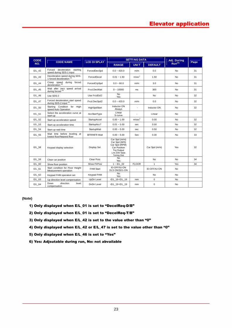
SETTING DATA CODE NO. CODE NAME LCD DISPLAY
RANGE UNIT DEFAULT Adj. During
Run(6) Page
E/L_42 Forced deceleration starting speed during SDS-1 input
ForcedDecSpd 0.0 ~ 420.0 m/m 0.0 No 31
E/L_43 Deceleration speed during SDS-1 forced deceleration (4)
ForcedDecel 0.01 ~ 1.50 m/sec2 1.50 No 31
E/L_44 Creep speed during forced deceleration (4)
ForcedCrpSpd 0.0 ~ 60.0 m/m 3.0 No 31
E/L_45 Wait after zero speed arrival during forced (4)
Frcd.DecWait 0 ~ 10000 ms 300 No 31
E/L_46 Use SDS-2 Use FrcdDcl2 No Yes No No 32
E/L_47 Forced deceleration start speed during SDS-2 input (5)
Frcd.DecSpd2 0.0 ~ 420.0 m/m 0.0 No 32
E/L_50 Starting Condition for High speed Auto Operation
HighSpdStart Inductor ON Always - Inductor ON No 32
E/L_51 Select the acceleration curve at start-up
AccStartType Linear S-curve - Linear No
E/L_52 Start-up acceleration speed StartupAccel 0.00 ~ 1.00 m/sec2 0.00 No 32
E/L_53 Start-up acceleration time StartupAccT 0.01 ~ 5.00 sec 0.50 No 32
E/L_54 Start-up wait time StartupWait 0.00 ~ 5.00 sec 0.50 No 32
E/L_55 Wait time before leveling at lowest floor/Nearest floor
BFR/NFR Wait 0.00 ~ 5.00 Sec 0.30 No 33
E/L_58 Keypad display selection Display Sel.
Car Spd (m/m) Car Spd (M/S) Car Spd (RPM)
Car Position Trq Output
Lmt.S/W State Tuning Dist
Car Spd (m/m) Yes 32
E/L_59 Clear car position Clear Posi. No Yes No No 34
E/L_60 Show floor position Show FlrPosi 1 ~ E/L_02 FLOOR 1 Yes 34
E/L_61 Start condition for Floor Height Measurement operation
FHM Start ID-OFF/IU-ON DLS ON/SD1-ON - ID-OFF/IU-ON No
E/L_62 Keypad FHM operation set Keypad FHM No Yes No No
E/L_63 Up direction level compensation UpDir Level -E/L_19~E/L_19 mm 0 No
E/L_64 Down direction level compensation
DnDir Level -E/L_19~E/L_19 mm 0 No
(Note)
1) Only displayed when E/L_01 is set to “DecelReq-D/B”
2) Only displayed when E/L_01 is set to “DecelReq-T/B”
3) Only displayed when E/L_42 is set to the value other than “0”
4) Only displayed when E/L_42 or E/L_47 is set to the value other than “0”
5) Only displayed when E/L_46 is set to “Yes”
6) Yes: Adjsutable during run, No: not abvailable
24
Elevator application
6 Elevator group
1) Jump code
You can move on to the code you want to check using E/L_00.
(Example) moving on to E/L_03
After pressing the [PROG] key, set 3 using [SHIFT/ESC] / [UP] / [DOWN] keys and press [ENT]. The following will be
displayed.
You can check the other codes using [UP] / [DOWN] keys.
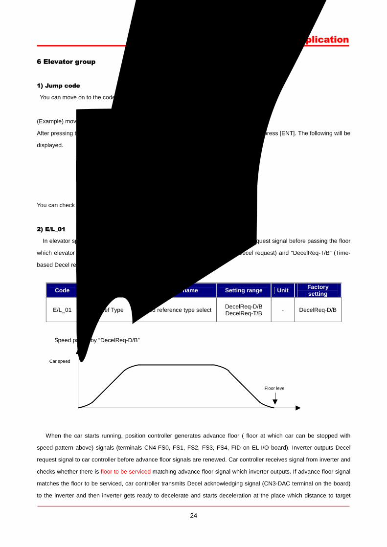
2) E/L_01
In elevator speed patten, two different speed patterns can be selected by Decel request signal before passing the floor
which elevator car can stop at. These are “DecelReq-D/B” (Distance-based Decel request) and “DecelReq-T/B” (Time-
based Decel request).
Code LCD display Parameter name Setting range Unit Factory setting
E/L_01 Spd Ref Type Speed reference type select DecelReq-D/B DecelReq-T/B - DecelReq-D/B
① Speed patten by “DecelReq-D/B”
When the car starts running, position controller generates advance floor ( floor at which car can be stopped with
speed pattern above) signals (terminals CN4-FS0, FS1, FS2, FS3, FS4, FID on EL-I/O board). Inverter outputs Decel
request signal to car controller before advance floor signals are renewed. Car controller receives signal from inverter and
checks whether there is floor to be serviced matching advance floor signal which inverter outputs. If advance floor signal
matches the floor to be serviced, car controller transmits Decel acknowledging signal (CN3-DAC terminal on the board)
to the inverter and then inverter gets ready to decelerate and starts deceleration at the place which distance to target
E/L Car Speed
03 120m/m
Floor level
Car speed
25
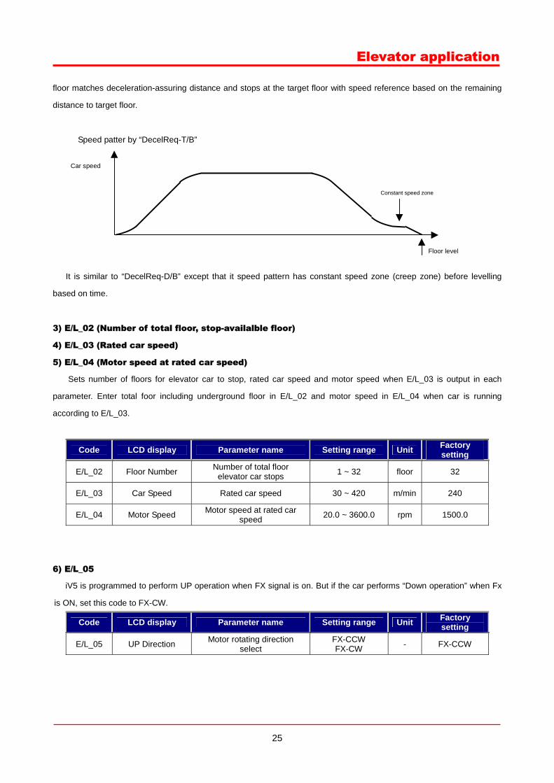
Elevator application
floor matches deceleration-assuring distance and stops at the target floor with speed reference based on the remaining
distance to target floor.
② Speed patter by “DecelReq-T/B”
It is similar to “DecelReq-D/B” except that it speed pattern has constant speed zone (creep zone) before levelling
based on time.
3) E/L_02 (Number of total floor, stop-availalble floor)
4) E/L_03 (Rated car speed)
5) E/L_04 (Motor speed at rated car speed)
Sets number of floors for elevator car to stop, rated car speed and motor speed when E/L_03 is output in each
parameter. Enter total foor including underground floor in E/L_02 and motor speed in E/L_04 when car is running
according to E/L_03.
Code LCD display Parameter name Setting range Unit Factory setting
E/L_02 Floor Number Number of total floor elevator car stops 1 ~ 32 floor 32
E/L_03 Car Speed Rated car speed 30 ~ 420 m/min 240
E/L_04 Motor Speed Motor speed at rated car speed 20.0 ~ 3600.0 rpm 1500.0
6) E/L_05
iV5 is programmed to perform UP operation when FX signal is on. But if the car performs “Down operation” when Fx
is ON, set this code to FX-CW.
Code LCD display Parameter name Setting range Unit Factory setting
E/L_05 UP Direction Motor rotating direction select
FX-CCW FX-CW - FX-CCW
Floor level
Car speed
Constant speed zone
26
Elevator application
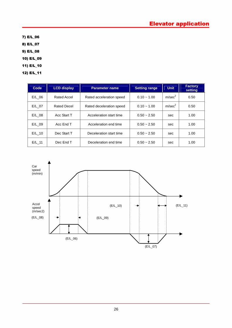
7) E/L_06
8) E/L_07
9) E/L_08
10) E/L_09
11) E/L_10
12) E/L_11
Code LCD display Parameter name Setting range Unit Factory setting
E/L_06 Rated Accel Rated acceleration speed 0.10 ~ 1.00 m/sec2 0.50
E/L_07 Rated Decel Rated deceleration speed 0.10 ~ 1.00 m/sec2 0.50
E/L_08 Acc Start T Acceleration start time 0.50 ~ 2.50 sec 1.00
E/L_09 Acc End T Acceleration end time 0.50 ~ 2.50 sec 1.00
E/L_10 Dec Start T Deceleration start time 0.50 ~ 2.50 sec 1.00
E/L_11 Dec End T Deceleration end time 0.50 ~ 2.50 sec 1.00
Accel speed (m/sec2)
(E/L_08)
(E/L_11) (E/L_10)
(E/L_09)
(E/L_07)
(E/L_06)
Car speed (m/min)
27
Elevator application
13) E/L_12
Compensates distance which car is moving while inverter sends decel request signal to car controller and receives
decel acknowledging signal. This value is used to calculate stop request floor.
Code LCD display Parameter name Setting range Unit Factory setting
E/L_12 CommDlyDist Communication delay compenstion distance 100 ~ 1000 mm 400
14) E/L_13
Deceleration start distance can be adjusted corresponding to speed controller characteristics and load quantity.
Deceleration starts at the place calculated by deceleration start distance from inverter plus E/L_13.
Code LCD display Parameter name Setting range Unit Factory setting
E/L_13 DecStartAdj Deceleration start adjustment -10 ~ 20 mm 0
15) E/L_14
Time taken to output traction machine Brake ON command to BRA-BRB terminal on the board after FX/RX is input.
16) E/L_15
Time taken to output elevator speed command after traction machine Brake ON command is output to BRA-BRB
terminal on the board after FX/RX is input.
17) E/L_16
Can set the time to maintain zero speed after elevator car speed became zero speed. There is a delay time for traction
machine brake to activate after FX/RX command is off, triggering brake command off. If inverter does not output stopping
torque at zero speed, elevator car may move Up or Down operation depending on load quantity.
18) E/L_17
Time taken to restart after stop.
Code LCD display Parameter name Setting range Unit Factory setting
E/L_14 PreExct Time Pre-excitation time 100 ~ 10000 msec 300
E/L_15 Brake Time Brake open time 0 ~ 10000 msec 300
E/L_16 Hold Time Hold time 0 ~ 10000 msec 300
E/L_17 Restart Time Wait time before Restart 0.00 ~ 100.00 sec 1.00
28
Elevator application
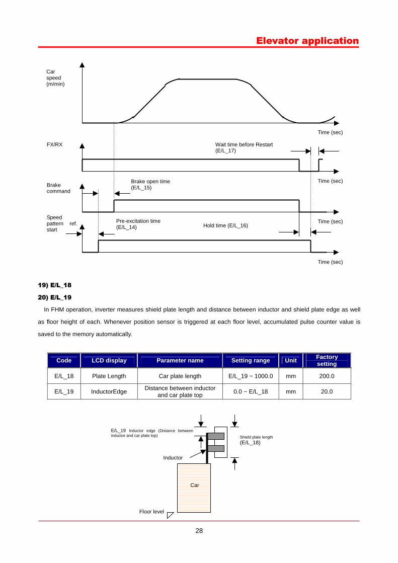
19) E/L_18
20) E/L_19
In FHM operation, inverter measures shield plate length and distance between inductor and shield plate edge as well
as floor height of each. Whenever position sensor is triggered at each floor level, accumulated pulse counter value is
saved to the memory automatically.
Code LCD display Parameter name Setting range Unit Factory setting
E/L_18 Plate Length Car plate length E/L_19 ~ 1000.0 mm 200.0
E/L_19 InductorEdge Distance between inductor and car plate top 0.0 ~ E/L_18 mm 20.0
Wait time before Restart (E/L_17)
Hold time (E/L_16)
Brake open time (E/L_15)
FX/RX
Time (sec)
Car speed (m/min)
Brake command
Time (sec)
Time (sec) Pre-excitation time (E/L_14)
Speed pattern ref. start
Time (sec)
Car
Inductor
Shield plate length(E/L_18)
Floor level
E/L_19 Inductor edge (Distance betweeninductor and car plate top)
29
Elevator application
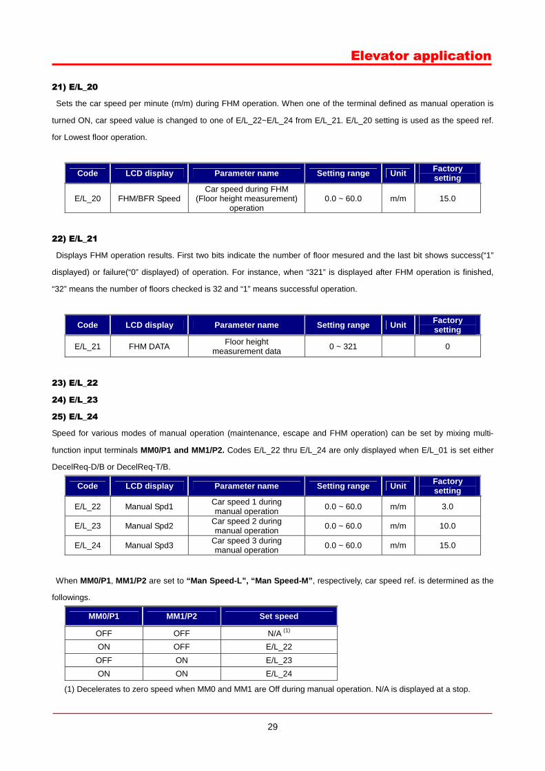
21) E/L_20
Sets the car speed per minute (m/m) during FHM operation. When one of the terminal defined as manual operation is
turned ON, car speed value is changed to one of E/L_22~E/L_24 from E/L_21. E/L_20 setting is used as the speed ref.
for Lowest floor operation.
Code LCD display Parameter name Setting range Unit Factory setting
E/L_20 FHM/BFR Speed Car speed during FHM
(Floor height measurement) operation
0.0 ~ 60.0 m/m 15.0
22) E/L_21
Displays FHM operation results. First two bits indicate the number of floor mesured and the last bit shows success(“1”
displayed) or failure(“0” displayed) of operation. For instance, when “321” is displayed after FHM operation is finished,
“32” means the number of floors checked is 32 and “1” means successful operation.
Code LCD display Parameter name Setting range Unit Factory setting
E/L_21 FHM DATA Floor height measurement data 0 ~ 321 0
23) E/L_22
24) E/L_23
25) E/L_24
Speed for various modes of manual operation (maintenance, escape and FHM operation) can be set by mixing multi-
function input terminals MM0/P1 and MM1/P2. Codes E/L_22 thru E/L_24 are only displayed when E/L_01 is set either
DecelReq-D/B or DecelReq-T/B.
Code LCD display Parameter name Setting range Unit Factory setting
E/L_22 Manual Spd1 Car speed 1 during manual operation 0.0 ~ 60.0 m/m 3.0
E/L_23 Manual Spd2 Car speed 2 during manual operation 0.0 ~ 60.0 m/m 10.0
E/L_24 Manual Spd3 Car speed 3 during manual operation 0.0 ~ 60.0 m/m 15.0
When MM0/P1, MM1/P2 are set to “Man Speed-L”, “Man Speed-M”, respectively, car speed ref. is determined as the
followings.
MM0/P1 MM1/P2 Set speed
OFF OFF N/A (1) ON OFF E/L_22 OFF ON E/L_23 ON ON E/L_24
(1) Decelerates to zero speed when MM0 and MM1 are Off during manual operation. N/A is displayed at a stop.
30
Elevator application
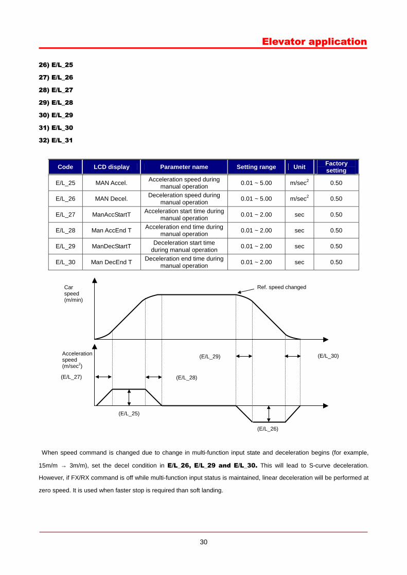
26) E/L_25
27) E/L_26
28) E/L_27
29) E/L_28
30) E/L_29
31) E/L_30
32) E/L_31
Code LCD display Parameter name Setting range Unit Factory setting
E/L_25 MAN Accel. Acceleration speed during manual operation 0.01 ~ 5.00 m/sec2 0.50
E/L_26 MAN Decel. Deceleration speed during manual operation 0.01 ~ 5.00 m/sec2 0.50
E/L_27 ManAccStartT Acceleration start time during manual operation 0.01 ~ 2.00 sec 0.50
E/L_28 Man AccEnd T Acceleration end time during manual operation 0.01 ~ 2.00 sec 0.50
E/L_29 ManDecStartT Deceleration start time during manual operation 0.01 ~ 2.00 sec 0.50
E/L_30 Man DecEnd T Deceleration end time during manual operation 0.01 ~ 2.00 sec 0.50
When speed command is changed due to change in multi-function input state and deceleration begins (for example,
15m/m → 3m/m), set the decel condition in E/L_26, E/L_29 and E/L_30. This will lead to S-curve deceleration.
However, if FX/RX command is off while multi-function input status is maintained, linear deceleration will be performed at
zero speed. It is used when faster stop is required than soft landing.
Acceleration speed (m/sec2)
(E/L_27)
(E/L_30)
(E/L_29)
(E/L_28)
(E/L_26)
(E/L_25)
Car speed (m/min)
Ref. speed changed
31
Elevator application
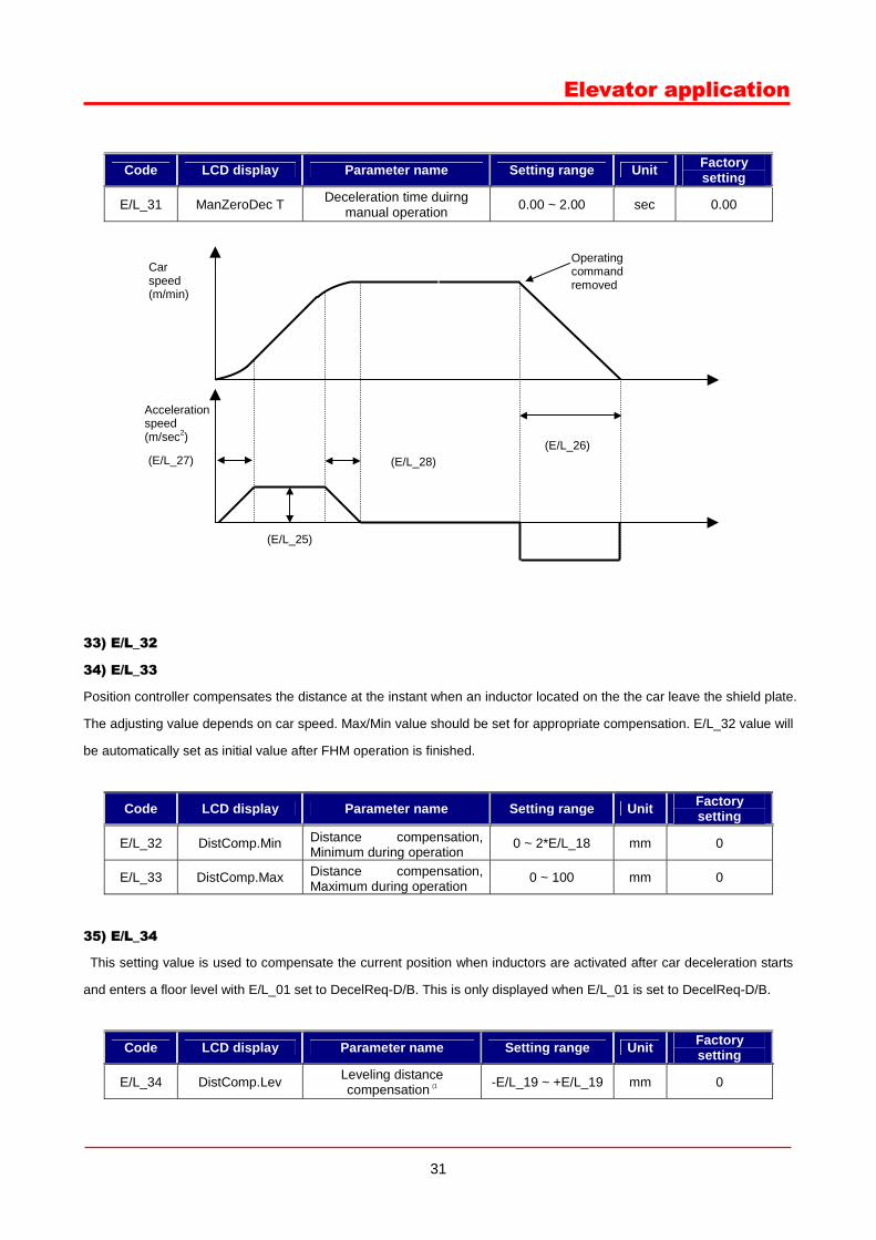
Code LCD display Parameter name Setting range Unit Factory setting
E/L_31 ManZeroDec T Deceleration time duirng manual operation 0.00 ~ 2.00 sec 0.00
33) E/L_32
34) E/L_33
Position controller compensates the distance at the instant when an inductor located on the the car leave the shield plate.
The adjusting value depends on car speed. Max/Min value should be set for appropriate compensation. E/L_32 value will
be automatically set as initial value after FHM operation is finished.
Code LCD display Parameter name Setting range Unit Factory setting
E/L_32 DistComp.Min Distance compensation, Minimum during operation
0 ~ 2*E/L_18 mm 0
E/L_33 DistComp.Max Distance compensation, Maximum during operation
0 ~ 100 mm 0
35) E/L_34
This setting value is used to compensate the current position when inductors are activated after car deceleration starts
and enters a floor level with E/L_01 set to DecelReq-D/B. This is only displayed when E/L_01 is set to DecelReq-D/B.
Code LCD display Parameter name Setting range Unit Factory setting
E/L_34 DistComp.Lev Leveling distance compensation (1 -E/L_19 ~ +E/L_19 mm 0
Acceleration speed (m/sec2)
(E/L_27) (E/L_28) (E/L_26)
(E/L_25)
Car speed (m/min)
Operating command removed
32
Elevator application
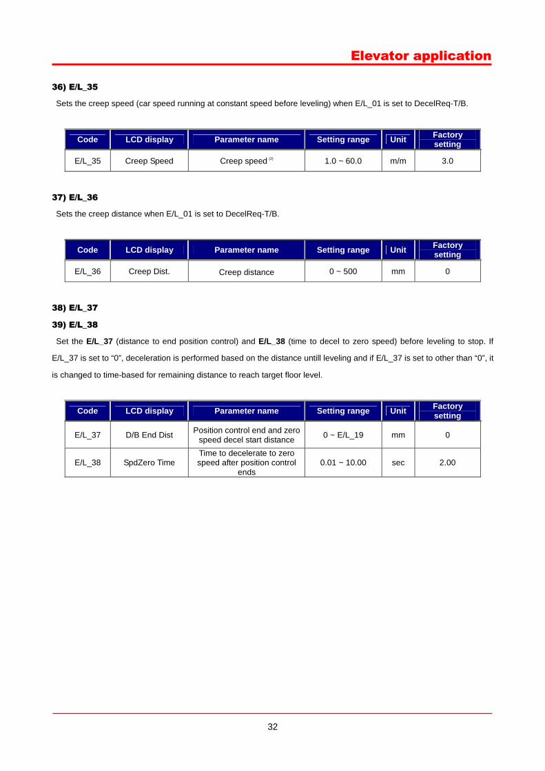
36) E/L_35
Sets the creep speed (car speed running at constant speed before leveling) when E/L_01 is set to DecelReq-T/B.
Code LCD display Parameter name Setting range Unit Factory setting
E/L_35 Creep Speed Creep speed (2) 1.0 ~ 60.0 m/m 3.0
37) E/L_36
Sets the creep distance when E/L_01 is set to DecelReq-T/B.
Code LCD display Parameter name Setting range Unit Factory setting
E/L_36 Creep Dist. Creep distance 0 ~ 500 mm 0
38) E/L_37
39) E/L_38
Set the E/L_37 (distance to end position control) and E/L_38 (time to decel to zero speed) before leveling to stop. If
E/L_37 is set to “0”, deceleration is performed based on the distance untill leveling and if E/L_37 is set to other than “0”, it
is changed to time-based for remaining distance to reach target floor level.
Code LCD display Parameter name Setting range Unit Factory setting
E/L_37 D/B End Dist Position control end and zero speed decel start distance 0 ~ E/L_19 mm 0
E/L_38 SpdZero Time Time to decelerate to zero speed after position control
ends 0.01 ~ 10.00 sec 2.00
33
Elevator application
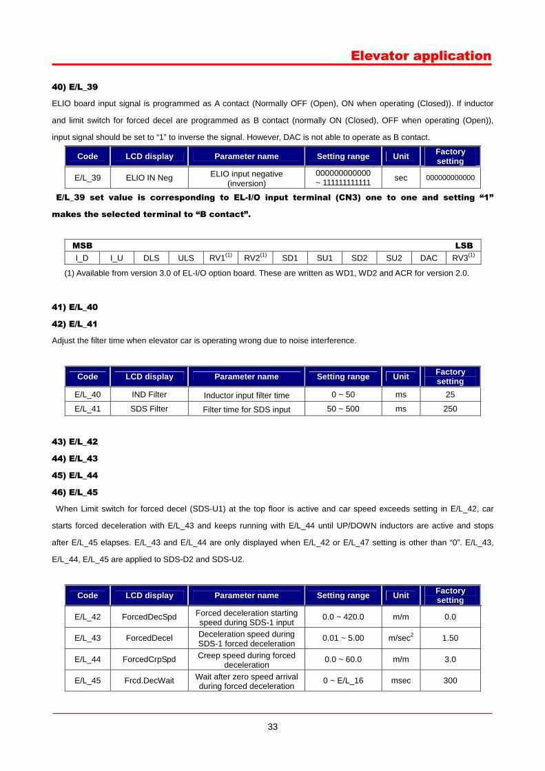
40) E/L_39
ELIO board input signal is programmed as A contact (Normally OFF (Open), ON when operating (Closed)). If inductor
and limit switch for forced decel are programmed as B contact (normally ON (Closed), OFF when operating (Open)),
input signal should be set to “1” to inverse the signal. However, DAC is not able to operate as B contact.
Code LCD display Parameter name Setting range Unit Factory setting
E/L_39 ELIO IN Neg ELIO input negative (inversion)
000000000000 ~ 111111111111 sec 000000000000
E/L_39 set value is corresponding to EL-I/O input terminal (CN3) one to one and setting “1”
makes the selected terminal to “B contact”.
MSB LSBI_D I_U DLS ULS RV1(1) RV2(1) SD1 SU1 SD2 SU2 DAC RV3(1)
(1) Available from version 3.0 of EL-I/O option board. These are written as WD1, WD2 and ACR for version 2.0.
41) E/L_40
42) E/L_41
Adjust the filter time when elevator car is operating wrong due to noise interference.
Code LCD display Parameter name Setting range Unit Factory setting
E/L_40 IND Filter Inductor input filter time 0 ~ 50 ms 25
E/L_41 SDS Filter Filter time for SDS input 50 ~ 500 ms 250
43) E/L_42
44) E/L_43
45) E/L_44
46) E/L_45
When Limit switch for forced decel (SDS-U1) at the top floor is active and car speed exceeds setting in E/L_42, car
starts forced deceleration with E/L_43 and keeps running with E/L_44 until UP/DOWN inductors are active and stops
after E/L_45 elapses. E/L_43 and E/L_44 are only displayed when E/L_42 or E/L_47 setting is other than “0”. E/L_43,
E/L_44, E/L_45 are applied to SDS-D2 and SDS-U2.
Code LCD display Parameter name Setting range Unit Factory setting
E/L_42 ForcedDecSpd Forced deceleration starting speed during SDS-1 input
0.0 ~ 420.0 m/m 0.0
E/L_43 ForcedDecel Deceleration speed during SDS-1 forced deceleration
0.01 ~ 5.00 m/sec2 1.50
E/L_44 ForcedCrpSpd Creep speed during forced deceleration
0.0 ~ 60.0 m/m 3.0
E/L_45 Frcd.DecWait Wait after zero speed arrival during forced deceleration
0 ~ E/L_16 msec 300
34
Elevator application
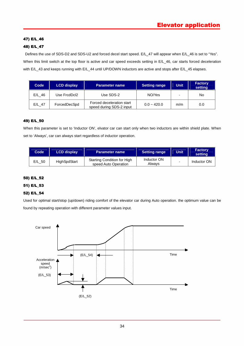
47) E/L_46
48) E/L_47
Defines the use of SDS-D2 and SDS-U2 and forced decel start speed. E/L_47 will appear when E/L_46 is set to “Yes”.
When this limit switch at the top floor is active and car speed exceeds setting in E/L_46, car starts forced deceleration
with E/L_43 and keeps running with E/L_44 until UP/DOWN inductors are active and stops after E/L_45 elapses.
Code LCD display Parameter name Setting range Unit Factory setting
E/L_46 Use FrcdDcl2 Use SDS-2 NO/Yes - No
E/L_47 ForcedDecSpd Forced deceleration start speed during SDS-2 input
0.0 ~ 420.0 m/m 0.0
49) E/L_50
When this parameter is set to ‘Inductor ON’, elvator car can start only when two inductors are within shield plate. When
set to ‘Always’, car can always start regardless of inductor operation.
Code LCD display Parameter name Setting range Unit Factory setting
E/L_50 HighSpdStart Starting Condition for High speed Auto Operation
Inductor ON Always - Inductor ON
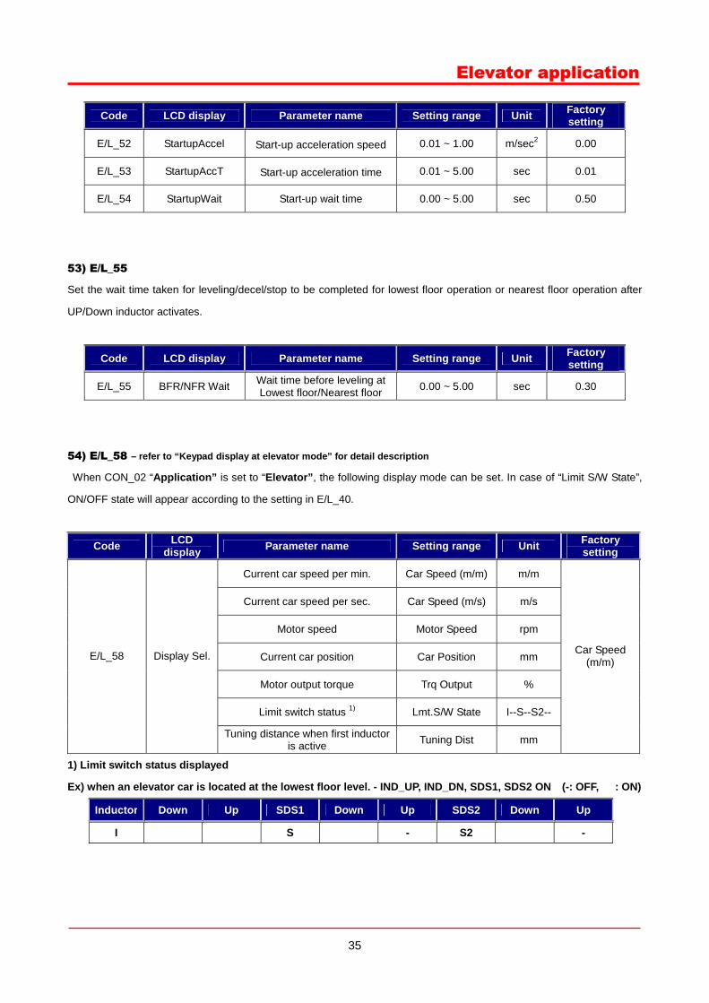
50) E/L_52
51) E/L_53
52) E/L_54
Used for optimal start/stop (up/down) riding comfort of the elevator car during Auto operation. the optimum value can be
found by repeating operation with different parameter values input.
(E/L_53)
Acceleration speed
(m/sec2)
(E/L_52)
(E/L_54)
Car speed
Time
Time
35
Elevator application
Code LCD display Parameter name Setting range Unit Factory setting
E/L_52 StartupAccel Start-up acceleration speed 0.01 ~ 1.00 m/sec2 0.00
E/L_53 StartupAccT Start-up acceleration time 0.01 ~ 5.00 sec 0.01
E/L_54 StartupWait Start-up wait time 0.00 ~ 5.00 sec 0.50
53) E/L_55
Set the wait time taken for leveling/decel/stop to be completed for lowest floor operation or nearest floor operation after
UP/Down inductor activates.
Code LCD display Parameter name Setting range Unit Factory setting
E/L_55 BFR/NFR Wait Wait time before leveling at Lowest floor/Nearest floor 0.00 ~ 5.00 sec 0.30
54) E/L_58 – refer to “Keypad display at elevator mode” for detail description
When CON_02 “Application” is set to “Elevator”, the following display mode can be set. In case of “Limit S/W State”,
ON/OFF state will appear according to the setting in E/L_40.
Code LCD display Parameter name Setting range Unit Factory
setting
Current car speed per min. Car Speed (m/m) m/m
Current car speed per sec. Car Speed (m/s) m/s
Motor speed Motor Speed rpm
Current car position Car Position mm
Motor output torque Trq Output %
Limit switch status 1) Lmt.S/W State I--S--S2--
E/L_58 Display Sel.
Tuning distance when first inductor is active Tuning Dist mm
Car Speed (m/m)
1) Limit switch status displayed
Ex) when an elevator car is located at the lowest floor level. - IND_UP, IND_DN, SDS1, SDS2 ON (-: OFF, : ON)
Inductor Down Up SDS1 Down Up SDS2 Down Up
I S - S2 -
36
Elevator application
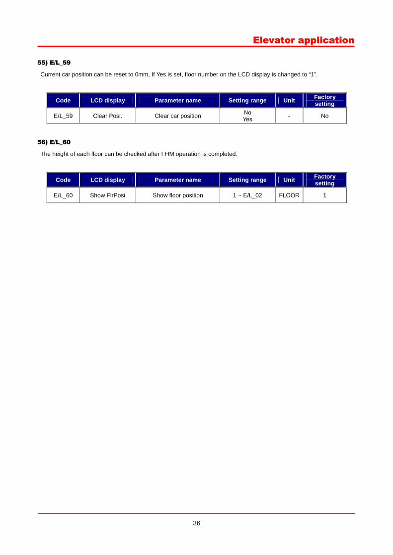
55) E/L_59
Current car position can be reset to 0mm, If Yes is set, floor number on the LCD display is changed to “1”.
Code LCD display Parameter name Setting range Unit Factory setting
E/L_59 Clear Posi. Clear car position No Yes - No
56) E/L_60
The height of each floor can be checked after FHM operation is completed.
Code LCD display Parameter name Setting range Unit Factory setting
E/L_60 Show FlrPosi Show floor position 1 ~ E/L_02 FLOOR 1