Embed Size (px)
Citation preview

NATIONAL OPEN UNIVERSITY OF NIGERIA
SCHOOL OF SCIENCE AND TECHNOLOGY
COURSE CODE: PHY 111
COURSE TITLE: Elementary Mechanics
PHY 111 ELEMENTARY MECHANICS
ii
Course Code PHY 111 Course Title Elementary Mechanics Course Team: Mr. Bankole Abiola, NOUN Dr. (Mrs.) C. Okonkwo, NOUN Dr. (Mrs.) R. U. Osuji, NOUN Dr. M. Oki, NOUN
Dr. H. M. Olaitan, Department of Physics, Lagos State University, Lagos
Course Editing Team: Dr. M. Oki Dr. (Mrs.) C. Okonkwo
Dr. H. M. Olaitan Depart of Physics, Lagos State University, Lagos
NATIONAL OPEN UNIVERSITY OF NIGERIA
PHY 111 ELEMENTARY MECHANICS
iii
National Open University of Nigeria Headquarters 14/16 Ahmadu Bello Way Victoria Island Lagos Abuja Annex 245 Samuel Adesujo Ademulegun Street Central Business District Opposite Arewa Suites Abuja e-mail: [email protected] URL: www.nou.edu.ng National Open University of Nigeria 2006 First Printed 2006 ISBN: 078-058-674-1 All Rights Reserved Printed by …………….. For National Open University of Nigeria
PHY 111 ELEMENTARY MECHANICS
iv
Table of Content Page Module 1 Unit 1: Space and Time.................................................. 1-8 Unit 2: Units and Dimensions........................................ 9-17 Unit 3: Vectors............................................................... 18-34 Unit 4: Vectors in Three Dimensions............................ 35-51 Unit 5: Linear Motion.................................................... 52-67 Module 2 Unit 1: Motion in More Than One Dimension............. 68-83 Unit 2: Force................................................................. 84-104 Unit 3: The Projectile Motion...................................... 105-114 Unit 4: Impulse and Linear Momentum....................... 115-128 Unit 5: Linear Collision .............................................. 129-147 Module 3 Unit 1: Gravitational Motion....................................... 148-162 Unit 2: Orbital Motion Under Gravity......................... 163-178 Unit 3: Gravitation and Extended Bodies Objects....... 179-193 Unit 4: Friction............................................................. 194-204 Unit 5: Work and Energy............................................. 205-218 Module 4 Unit 1: Simple Harmonic Motion I ............................ 219-232 Unit 2: Simple Harmonic Motion II............................ 233-248 Unit 3: Simple Harmonic Motion III.......................... 249-260 Unit 4: Rigid Body Dynamics I.................................. 261-278 Unit 5: Rigid Body Dynamics II................................. 279-294
PHY 111 ELEMENTARY MECHANICS
1
Module 1 Unit 1: Space and Time Unit 2: Units and Dimensions Unit 3: Vectors Unit 4: Vectors in Three Dimensions Unit 5: Linear Motion UNIT 1 SPACE AND TIME CONTENTS 1.0 Introduction 2.0 Objectives 3.0 Main Body
3.1 Frame of Reference 3.1.1 Rest and Motion 3.1.2 All Motion is Relative 3.1.3 Specifying Frame of Reference 3.1.4 Inertial and Non-Inertial Frame of Reference 3.2 Concept of Space
3.2.1 Cartesian Coordinates 3.2.2 Polar Coordinates
3.3 Concept of Time 3.3.1 Setting the Standard of Time 4.0 Conclusion 5.0 Summary 6.0 Tutor Marked Assignments (TMAs) 7.0 References and further Reading 1.0 INTRODUCTION Have you had the chance of reading through the course guide yet? If yes, it means you have an idea of what we shall be discussing in this unit. This unit is very important because it sets the stage for understanding that branch of Physics that deals with motion, which we call mechanics. Everything in the universe is in constant motion including the tree or the rock which you probably think is not moving. The topics we shall cover in this unit which includes frame of reference, space and time will help you to understand that all motion is relative. This means that objects in the universe move relative to one another.
PHY 111 ELEMENTARY MECHANICS
2
2.0 OBJECTIVES By the end of this unit, you will be able to: 1. explain the terms relative motion and absolute motion. 2. define a frame of reference 3. explain the concept of time 4. draw and specify the position of a point in a two dimensional
space with reference to a fixed origin, O 5. list the two polar coordinates of point, P a distance r from the
origin of a fixed frame of reference. 3.0 MAIN BODY 3.1 Frame of Reference Under the frame of reference, we shall discuss rest and motion, relative motion, inertial and non-inertial frame of reference and related issues. 3.1.1 Rest and motion To help us to understand the concept of frame of reference we need to note certain observations that have been made by physicists about this physical world we are living in. One of such observations is that a body is said to be at rest when it does not change its position with time. It is said to be in motion when it changes its position with time. But to know if the position of an object changes with time or not, we require a point absolutely fixed in space to be known. Such a fixed or stationary point is not known to exist in the universe. This is because physicists have observed that everything in the universe is in constant motion including this earth we are living in. The earth revolves round the sun and at the same time rotates round its polar axis. The sun itself together with the planets bound to it is in constant whirling motion among the galaxy of stars. The planets are also in motion with respect to each other. We now see that even if a wrist watch you place on the surface of the earth seems to be at rest it is actually in motion because the earth in which it rests is in motion. We say that the wrist watch is in motion relative to the earth. This means that there is nothing like absolute rest position for any object. It will interest you to know that this is true, about you, whether you are now sitting or standing. Everything in the room where you are only seems to be at rest. They are not actually at rest because they are actually moving relative to the earth. We can then conclude that absolute rest has no meaning in reality. When we say that the wrist watch you placed on the ground is at rest we mean that it does not change position with respect to the earth. Rest here means relative rest. It is always important for you to remember that a body is at relative rest with respect
PHY 111 ELEMENTARY MECHANICS
3
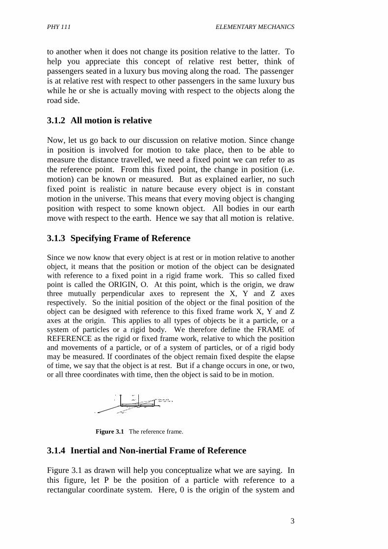
to another when it does not change its position relative to the latter. To help you appreciate this concept of relative rest better, think of passengers seated in a luxury bus moving along the road. The passenger is at relative rest with respect to other passengers in the same luxury bus while he or she is actually moving with respect to the objects along the road side. 3.1.2 All motion is relative Now, let us go back to our discussion on relative motion. Since change in position is involved for motion to take place, then to be able to measure the distance travelled, we need a fixed point we can refer to as the reference point. From this fixed point, the change in position (i.e. motion) can be known or measured. But as explained earlier, no such fixed point is realistic in nature because every object is in constant motion in the universe. This means that every moving object is changing position with respect to some known object. All bodies in our earth move with respect to the earth. Hence we say that all motion is relative. 3.1.3 Specifying Frame of Reference Since we now know that every object is at rest or in motion relative to another object, it means that the position or motion of the object can be designated with reference to a fixed point in a rigid frame work. This so called fixed point is called the ORIGIN, O. At this point, which is the origin, we draw three mutually perpendicular axes to represent the X, Y and Z axes respectively. So the initial position of the object or the final position of the object can be designed with reference to this fixed frame work X, Y and Z axes at the origin. This applies to all types of objects be it a particle, or a system of particles or a rigid body. We therefore define the FRAME of REFERENCE as the rigid or fixed frame work, relative to which the position and movements of a particle, or of a system of particles, or of a rigid body may be measured. If coordinates of the object remain fixed despite the elapse of time, we say that the object is at rest. But if a change occurs in one, or two, or all three coordinates with time, then the object is said to be in motion.
Figure 3.1 The reference frame.
3.1.4 Inertial and Non-inertial Frame of Reference Figure 3.1 as drawn will help you conceptualize what we are saying. In this figure, let P be the position of a particle with reference to a rectangular coordinate system. Here, 0 is the origin of the system and
Z
A P (x,y,z)A`
z`
x
x’x 0
oo` X
Y Y`
(x`,y`,z`)
Z
A P (x,y,z)A`
z`
x
x’x 0
oo` X
Y Y`
(x`,y`,z`)
PHY 111 ELEMENTARY MECHANICS
4
O X
Y
Yé
X`
r y
P(x,y)
xè
O X
Y
Yé
X`
r y
P(x,y)
xè
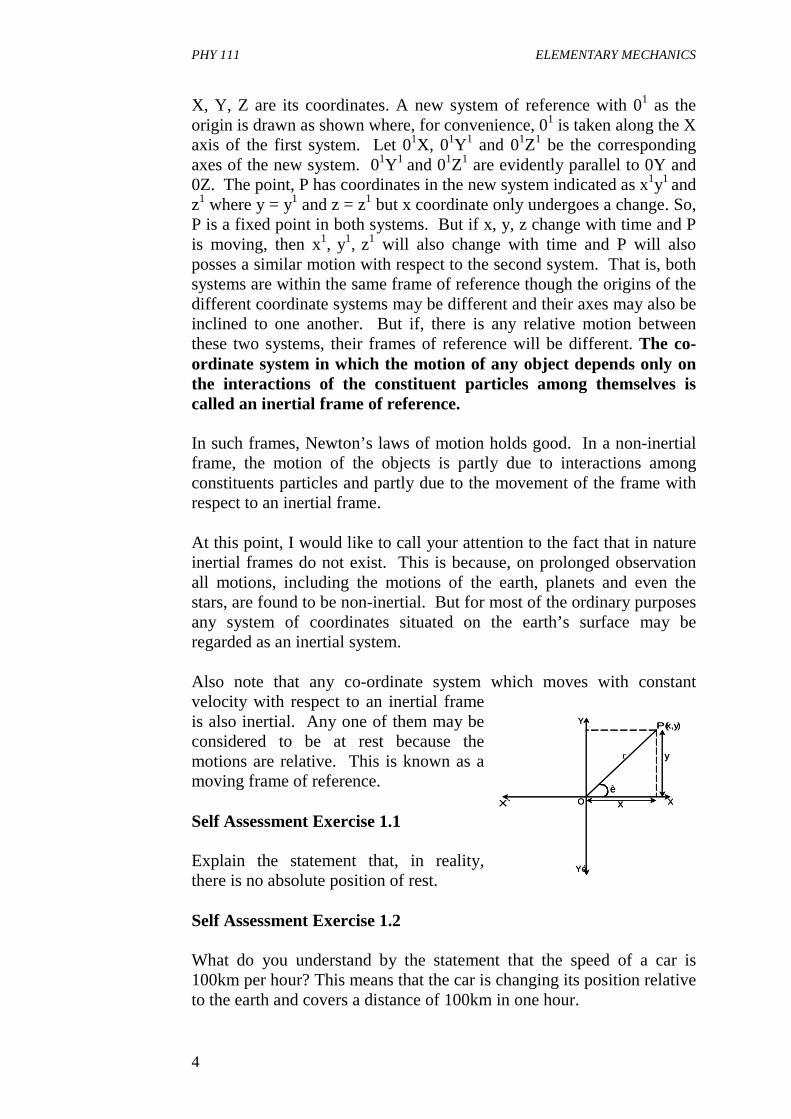
X, Y, Z are its coordinates. A new system of reference with 01 as the origin is drawn as shown where, for convenience, 01 is taken along the X axis of the first system. Let 01X, 01Y1 and 01Z1 be the corresponding axes of the new system. 01Y1 and 01Z1 are evidently parallel to 0Y and 0Z. The point, P has coordinates in the new system indicated as x1y1 and z1 where y = y1 and z = z1 but x coordinate only undergoes a change. So, P is a fixed point in both systems. But if x, y, z change with time and P is moving, then x1, y1, z1 will also change with time and P will also posses a similar motion with respect to the second system. That is, both systems are within the same frame of reference though the origins of the different coordinate systems may be different and their axes may also be inclined to one another. But if, there is any relative motion between these two systems, their frames of reference will be different. The co-ordinate system in which the motion of any object depends only on the interactions of the constituent particles among themselves is called an inertial frame of reference. In such frames, Newton’s laws of motion holds good. In a non-inertial frame, the motion of the objects is partly due to interactions among constituents particles and partly due to the movement of the frame with respect to an inertial frame. At this point, I would like to call your attention to the fact that in nature inertial frames do not exist. This is because, on prolonged observation all motions, including the motions of the earth, planets and even the stars, are found to be non-inertial. But for most of the ordinary purposes any system of coordinates situated on the earth’s surface may be regarded as an inertial system. Also note that any co-ordinate system which moves with constant velocity with respect to an inertial frame is also inertial. Any one of them may be considered to be at rest because the motions are relative. This is known as a moving frame of reference. Self Assessment Exercise 1.1 Explain the statement that, in reality, there is no absolute position of rest. Self Assessment Exercise 1.2 What do you understand by the statement that the speed of a car is 100km per hour? This means that the car is changing its position relative to the earth and covers a distance of 100km in one hour.
PHY 111 ELEMENTARY MECHANICS
5
0 3 12 2P r x y= = + .
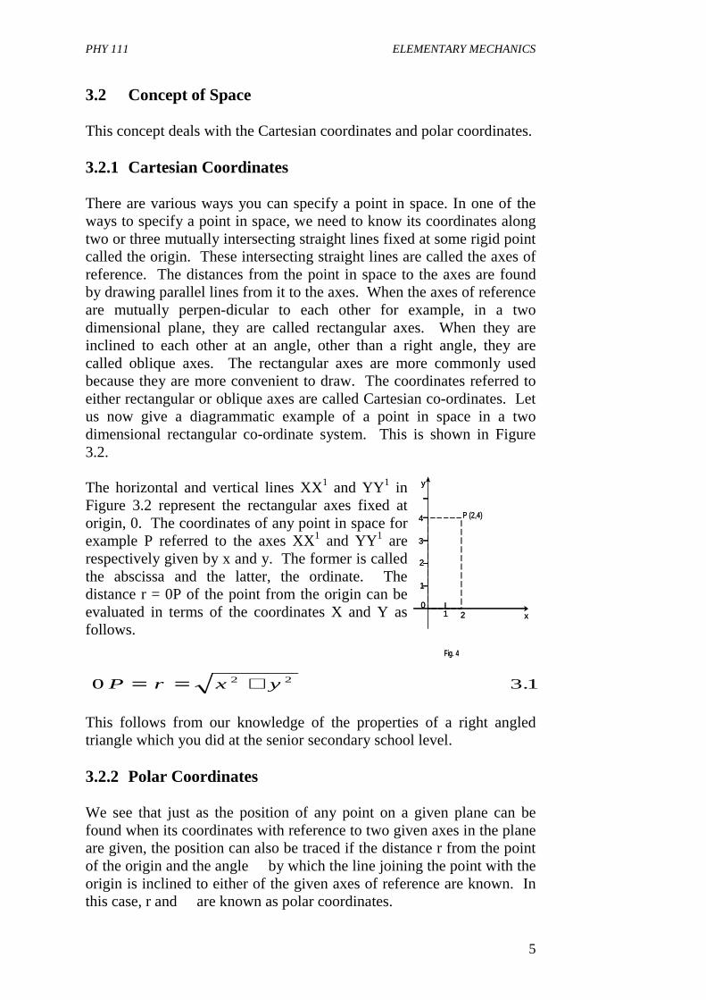
3.2 Concept of Space This concept deals with the Cartesian coordinates and polar coordinates. 3.2.1 Cartesian Coordinates There are various ways you can specify a point in space. In one of the ways to specify a point in space, we need to know its coordinates along two or three mutually intersecting straight lines fixed at some rigid point called the origin. These intersecting straight lines are called the axes of reference. The distances from the point in space to the axes are found by drawing parallel lines from it to the axes. When the axes of reference are mutually perpen-dicular to each other for example, in a two dimensional plane, they are called rectangular axes. When they are inclined to each other at an angle, other than a right angle, they are called oblique axes. The rectangular axes are more commonly used because they are more convenient to draw. The coordinates referred to either rectangular or oblique axes are called Cartesian co-ordinates. Let us now give a diagrammatic example of a point in space in a two dimensional rectangular co-ordinate system. This is shown in Figure 3.2. The horizontal and vertical lines XX1 and YY1 in Figure 3.2 represent the rectangular axes fixed at origin, 0. The coordinates of any point in space for example P referred to the axes XX1 and YY1 are respectively given by x and y. The former is called the abscissa and the latter, the ordinate. The distance r = 0P of the point from the origin can be evaluated in terms of the coordinates X and Y as follows. This follows from our knowledge of the properties of a right angled triangle which you did at the senior secondary school level. 3.2.2 Polar Coordinates We see that just as the position of any point on a given plane can be found when its coordinates with reference to two given axes in the plane are given, the position can also be traced if the distance r from the point of the origin and the angle � by which the line joining the point with the origin is inclined to either of the given axes of reference are known. In this case, r and � are known as polar coordinates.
0
1
2
3
4
1 2 x
y
P (2,4)
Fig. 4
0
1
2
3
4
1 2 x
y
P (2,4)
Fig. 4
PHY 111 ELEMENTARY MECHANICS
6
Here r sin 0 = y 3.2 And r cos 0 = x 3.3 So, we get the same relation r2 = r2(sin2 0 + cos2 0 ) 3.4 = y2 + x2
or that
3.6
These two methods of specifying a point in a rectangular plane are used in our daily life. Furthermore, to find the position of a point in space, its coordinates referred to three mutually perpendicular axes meeting at a common fixed origin must be known. Thus to locate a point in space requires a three-dimensional rectangular co-ordinate system having three axes x, y, and z. Self Assessment Exercise 1. 3 Draw a diagram showing the Cartesian co-ordinates of a point P(2,4) in a plane surface. The Cartesian coordinates of a point P (2,4) is as shown in the diagram Fig 3.3 .It means that with reference to some fixed origin O , the location of the point is 2 units along X-axis from the origin ,O and 4 units from O along the y-axis. 3.3 Concept of Time 3.3.1 Setting the standard of time You remember that from our knowledge of Geography the earth rotates round its polar axis. It completes one rotation in what we call a complete day. This complete day consists of the day time and night time segments of the earth’s rotation. This is because during the day time segment we see the sunlight but during the night time segment the sunlight is obscured from us and we see just darkness. The sun appears to us to move across the sky because of this diurnal rotation of the earth about its polar axis. The meridian at a place is an imaginary vertical plane through it. The sun is said to be in the meridian when it reaches the highest position in the course of its apparent journey in the sky. The interval of time between two successive transitions of the centre of the sun’s disc across the meridian at any place is called a solar day. The
r x y= +2 2
PHY 111 ELEMENTARY MECHANICS
7
length of this solar day varies from day to day because of many reasons but the same cycle of variations repeats after a solar year which is 365½days, approximately. The mean of the actual solar days averaged over a full year is called the mean solar day. A clock, watch or chronometer keeps the mean solar time. These are regulated against standard clocks and chronometers controlled under specific conditions. So, this periodic appearances of the sun overhead, averaged over a year and called the mean solar day had helped us to capture the concept of time. The time interval between successful appearances gives the standard of time. This was the situation before 1960. With developments in science, the standard of time was changed to the periodic time of the radiation corresponding to the transition between the two energy levels of the fundamental state of the atom caesium-133. The mean solar day is divided into 24 hours. An hour is divided into 60 minutes and a minute is divided into 60 seconds. Therefore, The mean solar day = 24hrs x 60min x 60secs = 86,400 mean solar Seconds ….. 3.7 This means that a mean solar second is 86,400th part of the mean solar day. This gives the unit of time known as the second. Using the standard of time as the periodic time associated with a transition between two energy levels of cesium-133 atom, 1 second = 9, 192,631,170 cesium periods. ….. 3.8 What has helped us to understand the concept of time? Any thing that happens periodically. For example, the periodic appearance of the sun over a particular location on the earth. 4.0 CONCLUSION In this unit you have learnt that every object in space is in motion. • that a body is at relative rest with respect to another, so there is
nothing like absolute rest. • that the Cartesian co-ordinates and the polar coordinates are used to
locate a point in space with reference to a fixed origin. • that the periodic appearance of the sun at a particular location on
earth or any other periodic happening has helped us understand the concept of time.
PHY 111 ELEMENTARY MECHANICS
8
5.0 SUMMARY What you have learnt in this unit • concerns frame of reference which helps us locate any point or object
in space. • you have learnt that rest and motion are all relative. • you have learnt how time is determined. 6.0 TUTOR MARKED ASSIGNMENTS 1. Explain the terms ‘absolute motion’ and relative motion. Which
one of them is more important to man, and why? 2. Explain what is meant by frame of reference. What is the
significance of coordinates of a point in a three dimensional Cartesian system.
7.0 REFERENCES AND FURTHER READINGS Das Sarma J.M An Introduction to Higher Secondary Physics. Modern
Book Agency Private Ltd., India.
PHY 111 ELEMENTARY MECHANICS
ix
Fishbane, P. M, Gasiorowicz, S., and Thronton, S. T.(1996), Physics for
Scientists and Engineers. 2nd Edition Vol. 1. Prentice Hall Upper Saddle River New Jersey.
Sears, F. W., Zemansky, M. W. and Young, H. D. (1975).College
Physics 4th Edition Addison-Wesley Pub. Co. Inc., Reading, U. K.
UNIT 2 UNITS AND DIMENSIONS CONTENTS 1.0 Introduction 2.0 Objectives 3.0 Main Body
3.1 Units of Measurement 3.1.1 Definition of the Standards of Length, Time and
Mass 3.2 Fundamental and Derived Units 3.2.1 What is a Fundamental Unit? 3.2.2 What is a Derive Unit? 3.2.3 Some Units of Length, Mass and Time in Common
Use in Science 3.3 Dimensional Analysis 3.3.1 What is Dimension? 3.3.2 What is a Dimensional Equation?
4.0 Conclusion 5.0 Summary 6.0 Tutor Marked Assignments (TMAs) 7.0 References and Further Reading
PHY 111 ELEMENTARY MECHANICS
10
1.0 INTRODUCTION Today, we shall learn about units and measurements. Our minds will go readily to traders in the market who sells grains like rice, garri or others who sell clothing materials. These traders do one form of measurement or the other, depending on what they are selling. For example, the garri seller measures the garri with a specific type and size of measuring cup. The particular type and size of cup has been accepted by the grarri traders union as the unit of measurement. In this way, they set their own standard of measurements. Another example is that when you measure the height of a man, you are comparing him to a meter stick. Science takes note of what is around us and tries to explain it. Therefore, we say that science speculates, observes and analyses etc. The whole basis of science is rooted in measurement. This is why this unit of our course is very important. There are always two aspects to measurement. When you say that a person’s height is 1.4m, you notice that in the expression of the height of the person, you have a number (that is, 1.4) and a unit (that is, m for metres). You immediately see that the measurement of a physical quantity consists of a pure number and a unit. 2.0 OBJECTIVES At the end of this unit, you will be able to: • Explain what is meant by a unit of measurement • State the different systems of measurement in physics • List the Fundamental Units • Distinguish between a fundamental unit and a derived unit • Determine the units of a physical quaintly given the dimensions 3.0 MAIN BODY 3.1 Units of Measurement Fundamental and derived units are discussed and some common units are discussed. And some common units of measurements are enumerated. 3.1.1 Definition of the Standards for Length, Time and Mass Important because it makes for uniformity in experiments in physics no
PHY 111 ELEMENTARY MECHANICS
11
matter where it is carried out in the world as we saw in the introduction to this section of the course. A very long time ago, people used what was available as standards for measurement. Measurement of length using the “foot” came into use in this manner. Here, the foot is defined as: The average length of the feet of 20 Gerrman men. Now, just as the union of garri traders accepted a specific type and size of measuring cup as their standard for the sake of uniformity, in 1791 French scientists established the forerunner of the international system of measurements. They defined the meter, the second and the kilogram. • The metre was defined as one ten-millionth (10-7) of the distance
along Earth’ssurface between the equator and the North pole. • The second was defined as 1/86,400 of a mean solar day. • The kilogram was defined as the mass of a certain quantity of water.
In 1889, an International organization called the General conference on weights and measures was formed. Their mission was to periodically meet and refine these units of measurement. Therefore, in 1960, this organisation named the system of unit s based on the metre, kilogram and second the International System abbreviated SI (meaning in French -Systeme International). This system is also known as the metric system or mks system (after metre, kilogram and second). Other systems of measurement exist. This include the cgs system (meaning-centimeter-gram-second). The F.P.S. system (British system) [meaning foot(ft),pound (lb) and second(s)] The metre, the second and the kilogram are the units we use in measuring length, time and mass. Hence we define the unit as - The convenient quantity used as the standard of measurement of
a physical quantity. To explain this further I can say that the numerical measure of a given quantity is the number of times the unit for it is contained in the quantity. To illustrate this, Get a long stick and measure it with a metre rule. Assuming you measured out five lengths of the metre. It means that the length of the stick you brought is 5 times the length of the metre rule which is 1metre. Hence the value of the length of the stick is 5metres (written 5m). Can you try this?
PHY 111 ELEMENTARY MECHANICS
12
I would like to draw your attention to the fact that every physical quantity requires a separate unit for its measurement. For example, the unit of area is the square metre (m2). 3.2 Fundamental and Derived Units Fundamental and derived units are discussed and some common units of measurements are enumerated. 3.2.1 What is a fundamental unit? These physical quantities, length, time and mass are known as the fundamental quantities. What this means is that length, time or mass can not be derived from any other quantity in physics and are independent of each other. So these three quantities are called the fundamental units. Recall that the unit of measurements of length is the metre, m. The unit of measurement of time is the second and the unit of measurement of mass is the kilogram. 3.2.2 What is a derived unit? Definition: The units of all physical quantities which are based on the three fundamental units are termed derived units. This is how to get derived unit from fundamental unit. The unit of area is the area of a square each side of which is of one unit length. Fig 3.1 shows the area of a square-the shaded portion. From our knowledge of mathematics, we know that area = length x width. The sides of a unit area have lengths 1m each. Therefore the value of the unit area is one square metre. The mathematical expression for it is 1m 1m
Fig. 3.1 Area = 1m x 1m = 1m2 This shows that the unit area is the square metre (written m2). Also the unit volume is the volume of a cube, each side of which is of unit length. We see that the unit of area or that of the volume is derived from the unit of length which is a fundamental unit. Velocity is another example of a physical quantity with a derived unit. A body has unit velocity when it moves over a distance of unit length in unit time in a
PHY 111 ELEMENTARY MECHANICS
13
constant direction or straight line. Therefore, the unit of velocity is derived from the units of length and time. Mathematically, we write Velocity = distance (metres, m) time (in seconds, s): .......3.1 :. The unit of velocity is metres per second written as ms-1 (or m/s). Self Assessment Exercise 3.1 Can you now determine or derive the unit of force. Recall the definition of force. This will help you derive the unit of force. We conclude that area, volume, velocity etc are all derived units. All the mechanical units, and units of all non-mechanical quantities like magnetism, electric, thermal, optical, etc can, with the help of some additional notions be derived from the three fundamental units of length, time and mass. This shows the true fundamental nature of these three units. 3.2.3 Some Units of Length, Mass and Time in Common Use. Some units of length in common use in science are: 1 angstrom unit = 1Α = 10-10 m (used by spectroscopists)...................3.2 1 nanometer = 1nm = 10-9m(used by optical designers).......................3.3 1 micrometer = 10-6m (used commonly in Biology)............................3.4 1 millimeter = 1mm = 10-3m and .........................................................3.5 1 centimeter = 1cm = 10-2m (used most often)...................................3.6 1 kilometer = 1km = 103m (a common unit of distance).....................3.7 The device used to subdivide the standard of mass, the kilogram, into equal Submasses is called the equal arm balance. The frequently used units of mass are: 1 microgram = 10g = 10-9 kg 3.8 1milligram = 10g = 10-6 kg 3.9 1gram = 1g = 10-3 kg 3.10 1pound mass = 1lb m = 0.45359237 kg 3.11 Units of length for very large distances:
PHY 111 ELEMENTARY MECHANICS
14
Some objects are very far apart from each other. The Astronomical unit is the unit used in measuring such very large distances. - 1Astronomical unit = 1.495 x 10⁸ km = 9.289 x 10⁷ miles ..........3.12 - 1 Astronomical unit, abbreviated 1 Au is taken to be the mean distance from earth to sun. Other units for measuring long distances are: - 1 Parsec = 3.083 x 10¹³ km = 1.916 x 10¹³ miles 3.13 - Light-year = Distance traveled by light in one year = 0.31 parsec = 5.94 x 10¹² miles .....3.14 The unit of time as we discussed in unit 1 of this module is the mean solar second. This applies to both the C.G.S and F.P.S systems of measurement. It is based on the mean solar day as the standard of time. If you recall from our discussions in unit 1, the solar day is divided into 24 hours, an hour into 60 minutes, and a minutes into 60 seconds. Therefore, recall that, The mean solar day = 24hrs x 60 minutes x 60 seconds = 86,400 mean solar seconds ......3.15 That is the mean solar second is 86, 400th part of the mean solar day. The mean solar second is taken to be the unit of time (i.e 1s). 3.3 Dimensional Analysis This section takes us through the definition of dimensional analysis and dimensional equations. 3.3.1 What is dimension? Three basic ways to describe a physical quantity are the space it occupies, the matter it contains and how long it persists. All descriptions of matter, relationships and events are combinations of these three basic characteristics. We have also found that all measurements ultimately reduce to the measurement of length, time and mass. From our discussion on derived units above, we saw that any physical quantity, no matter how complex, can be expressed as an algebraic combination of these three basic quantities. For example we saw that velocity is length per time
The relation of the unit of any physical quantity to the fundamental units (length, mass and time) is indicated by what is known as the dimensions
PHY 111 ELEMENTARY MECHANICS
15
of the unit concerned. Example [Area] = [L x L]. Length, time and mass specify three primary dimensions. We use the abbreviations [L], [T] and [M] for these primary dimensions. Definition: The dimension of a physical quantity is the algebraic combination of [L], [T] and [M] from which the quantity is formed. Let us explain this further using the example of volume. The numerical value of volume, the unit volume is indicated by [V]. The dimensions of volume will therefore be given by [L3.M0.T0] or simply [L3]. For a unit volume it is [unit length x unit width x unit height] that is [L x L x L] or just [L3]. Thus, we say that volume has three dimensions in respect of length. Volume is not dependent of the units of mass and time. Another example to determine the dimensions of a physical quantity, velocity is as follows: Velocity = Displacement = L 3.16 Time T :. The dimensions of velocity is given by
[L] or [LT-1]. 3.3.2 What is a dimensional equation? The equation such as [V] = [L3 M0 T0] or [v] = [LT -1] is called dimensional equation. These dimensional equations tell us the relation between the derived units(Volume, Velocity, etc) and the fundamental units, length, mass and time of any system of measurement. The general expression for the dimension of any physical quantity is of the form [Lq Tr Ms] of the primary dimensions. The superscripts q, r, and s refer to the order (or power) of the dimension. For example, the dimension of area is [L2 To Mo]. It simply reduces to [L2]. So, if all the exponents q, r, and s are zero the combination will be dimensionless. Note that the exponents q, r and s can be positive integers, negative integers, or even fractional powers. The study of the dimensions of an equation is called dimensional analysis. Any equation that relates physical quantities must have consistent dimensions i.e, the dimensions on one side of an equation must be the same as those on the other side. One use of dimensional
PHY 111 ELEMENTARY MECHANICS
16
analysis is that it provides a valuable check for any calculations. The second use is that dimensional analysis helps us convert the units of a physical quantity from one absolute system to another absolute system. Self Assessment Exercise Using dimensional analysis, determine the units of acceleration. Further examples: [Acceleration] = [Velocity] = [distance] [Time] [Time x time] 3.17 = [L] = [LT -2] 3.18 [T2] Your answer shows that the units of acceleration is ms-2 Self Assessment Exercise [Coefficient of Linear Expansion]
= [Change in Length] .....3.19 [Original Length x Change of Temperature] [L] [L] x [degrees] = [degree-1] ......3.20 4.0 CONCLUSION In this Unit you have learnt that in making a measurement of any physical quantity, some definite and convenient quantity of the same kind is taken as the standard in terms of which the quantity as a whole is expressed. You have learnt also that this convenient quantity used as the standard of measurement is called a unit. You also learnt that some physical quantities are known as fundamental quantities. These are length, time and mass and their units of measurement are the metre, the second and the kilogram respectively. You also learnt that there are different systems of measurement. You learnt that the fundamental quantities are used to derive the units of all other physical quantities by using dimensional analysis. 5.0 SUMMARY What you have learnt in this unit concerns the $ meaning of a fundamental quantity $ meaning of the unit of a fundamental quantity
PHY 111 ELEMENTARY MECHANICS
17
$ different systems of measurement. This unit has helped you to be able to derive the units of any physical quantity in nature using dimensional analysis. You have also learnt some units of measurement in common use. The knowledge you have acquired in this unit will help you to do correct calculations and measurements in the whole of your physics and mathematics courses. In short, the whole of science hinges on measurement. So, you can see how important this Unit is. 6.0 TUTOR MARKED ASSIGNMENTS Newton’s law of universal gravitation gives the force between two objects of mass, m1, and m2, separated by a distance r, as
F = G (m1m2) r Use dimensional analysis to find the units of the gravitational constant, G. 7.0 REFERENCES AND FURTHER READING Das Sarma, J.M. (1978). An Introduction to Higher Secondary Physics.
Modern Book Agency Private Ltd. Fishbane, P. M; Gasiorowicz, S. and Thranton, S.T., (1996). Physics
for Scientists and Engineers. 2nd Edition Vol.1 prentice Hall, New Jersey.
Sears, F.W., Zemansky, M.W. and Young, H.D. (1974). Addison-
Wesley Pub. Co. Inc., Reading, U.K.
PHY 111 ELEMENTARY MECHANICS
18
UNIT 3 VECTORS CONTENT 1.0 Introduction 2.0 Objectives 3.0 Main Body
3.1 Definition and Representation of a Vector 3.1.1 Definition 3.1.2 Vector Notation 3.1.3 Representation of a Vector
3.2 Composition of Vectors 3.2.1 Parallelogram and Triangular Laws of Vector
Composition 3.3 Addition and Subtraction of Vectors
3.3.1 Addition of Vectors 3.3.1.1 Multiplication of a vector by a scalar 3.3.2 Subtraction of vectors 3.3.2.1 The Null Vector 3.3.2.2 The Unit vector
3.4 Components of a vector 3.4.1 Components of a vector in terms of unit vectors
PHY 111 ELEMENTARY MECHANICS
19
3.4.2 Components of a vector in terms of Plane Polar coordinates
4.0 Conclusion 5.0 Summary 6.0 Tutor Marked Assignments (TMAs) and Marking Scheme 7.0 References and Further Reading 1.0 INTRODUCTION When you read the topic of this unit which is ‘Vectors’, I know that in your mind you may be wondering why you have to study vectors. Questions like, of what use are they in physics? can also crop up in your mind. You may perhaps know the answers to these questions from your secondary school physics courses. It is interesting to know that vectors are used extensively in almost all branches of physics. In order to understand physics, you must know how to work with vectors, how to add, subtract and multiply vectors. You are, already familiar with some physical quantities such as velocity, acceleration and force. These are all vector quantities. What you have learnt in Units 1 and 2 will definitely aid your quick understanding of this Unit. In this Unit, we shall look afresh at vectors and build upon what you knew before now. We shall begin by defining vectors in a precise manner. You will learn how vectors are denoted and represented in the literature. You will also learn how to add and subtract vectors because, these will be applied in our study of motion, forces causing motion etc. 2.0 OBJECTIVES By the end of this unit, you should be able to: (i) define a vector (ii) express a vector in terms of its components in two dimensional
coordinate denote system (iii) Add and subtract vectors (iv) define the NULL vector (v) multiply a vector by a scalar quantity (vi) express a vector in terms of unit vectors in a plane. 3.0 MAIN BODY 3.1 Definition and Examples of Vector Quantities 3.1.1 Definition
PHY 111 ELEMENTARY MECHANICS
20
In the secondary school science courses, you must have studied scalar and vector quantities. You have learnt about physical quantities like mass, length, time, area, frequency, volume and temperature etc. You recall that a scalar quantity is completely specified by a single number (with a suitable choice of units). Many more examples of scalar quantities in physics exist. For example, the charge of an electron, resistance of a resistor, specific heat capacity of a substance, etc are all scalars. You also learnt about physical quantities like displacement, velocity, acceleration, momentum, force etc. As you know, these are all vector quantities. The definitions of a vector is as follows. Any physical quantity which requires both magnitude and direction for it to be completely specified is called a vector. Before we proceed to learn how vectors are represented, let us refresh our minds about vector notation.
3.1.2 Vector notation
When you read different books on vectors you will notice that writers denote vectors differently. Generally, vectors are denoted
by a letter in bold face type [A, B, C, etc] or by putting an arrow mark or a curly or straight line above the letter, or a curly or straight line below the letter, thus, . The magnitude of a vector is simply denoted by
the letter without an arrow mark as In this course, we shall use the
notation to denote a vector.
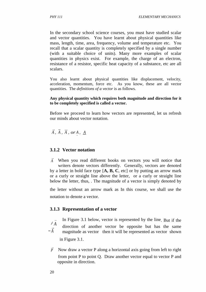
3.1.3 Representation of a vector
In Figure 3.1 below, vector is represented by the line. But if the direction of another vector be opposite but has the same magnitude as vector then it will be represented as vector shown
in Figure 3.1. Now draw a vector P along a horizontal axis going from left to right
from point P to point Q. Draw another vector equal to vector P and opposite in direction.
rA A A or A A,
~, , ,
~
rA
rAAB→
A→
−rA
rP
PHY 111 ELEMENTARY MECHANICS
21
-AA
A
B
Fig. 3.1
-AA
A
B
Fig. 3.1
-AA
A
B
Fig. 3.1
S R
QP
Fig. 3.2
S R
QP
S R
QP
Fig. 3.2
B
O A
CB
A
C = A + B
Fig. 3.3
� ���
�
B
O A
CB
A
C = A + B
Fig. 3.3
� ���
�
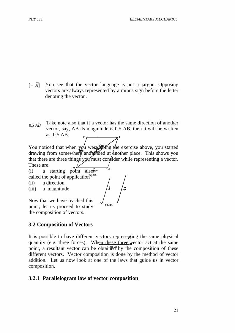
You see that the vector language is not a jargon. Opposing vectors are always represented by a minus sign before the letter denoting the vector .
Take note also that if a vector has the same direction of another vector, say, AB its magnitude is 0.5 AB, then it will be written as 0.5 AB
You noticed that when you were doing the exercise above, you started drawing from somewhere and ended at another place. This shows you that there are three things you must consider while representing a vector. These are: (i) a starting point also called the point of application (ii) a direction (iii) a magnitude Now that we have reached this point, let us proceed to study the composition of vectors. 3.2 Composition of Vectors It is possible to have different vectors representing the same physical quantity (e.g. three forces). When these three vector act at the same point, a resultant vector can be obtained by the composition of these different vectors. Vector composition is done by the method of vector addition. Let us now look at one of the laws that guide us in vector composition. 3.2.1 Parallelogram law of vector composition
[ ]−rA
AB→
0 5. AB→
PHY 111 ELEMENTARY MECHANICS
22
OC→
R = P
+ Q
Q
PO A
C
Fig. 3.4
��
�
�
�
R = P
+ Q
Q
PO A
C
Fig. 3.4
��
�
�
�
A
B
C
AB + BC = AC
Fig. 3.5
A
B
C
AB + BC = AC
Fig. 3.5
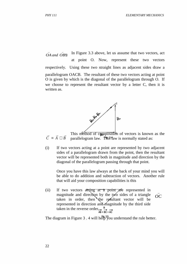
In Figure 3.3 above, let us assume that two vectors, act
at point O. Now, represent these two vectors
respectively. Using these two straight lines as adjacent sides draw a
parallelogram OACB. The resultant of these two vectors acting at point O is given by which is the diagonal of the parallelogram through O. If we choose to represent the resultant vector by a letter C, then it is written as.
This method of composition of vectors is known as the parallelogram law. This law is normally stated as:
(i) If two vectors acting at a point are represented by two adjacent sides of a parallelogram drawn from the point, then the resultant vector will be represented both in magnitude and direction by the diagonal of the parallelogram passing through that point.
Once you have this law always at the back of your mind you will
be able to do addition and subtraction of vectors. Another rule that will aid your composition capabilities is this
(ii) If two vectors acting at a point are represented in
magnitude and direction by the two sides of a triangle taken in order, then the resultant vector will be represented in direction and magnitude by the third side taken in the reverse order.
The diagram in Figure 3 . 4 will help you understand the rule better.
r rA and BOAand OB→ →
OAand OB→ →
r r rC A B= +
PHY 111 ELEMENTARY MECHANICS
23
r = ?
q
p
Fig. 3.6
� �
�
r = ?
q
p
Fig. 3.6
� �
�
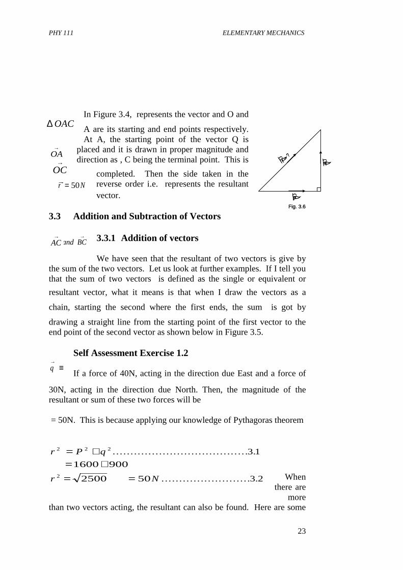
In Figure 3.4, represents the vector and O and
A are its starting and end points respectively. At A, the starting point of the vector Q is
placed and it is drawn in proper magnitude and direction as , C being the terminal point. This is
completed. Then the side taken in the reverse order i.e. represents the resultant vector.
3.3 Addition and Subtraction of Vectors
3.3.1 Addition of vectors We have seen that the resultant of two vectors is give by
the sum of the two vectors. Let us look at further examples. If I tell you that the sum of two vectors is defined as the single or equivalent or
resultant vector, what it means is that when I draw the vectors as a
chain, starting the second where the first ends, the sum is got by
drawing a straight line from the starting point of the first vector to the end point of the second vector as shown below in Figure 3.5.
Self Assessment Exercise 1.2 If a force of 40N, acting in the direction due East and a force of
30N, acting in the direction due North. Then, the magnitude of the resultant or sum of these two forces will be = 50N. This is because applying our knowledge of Pythagoras theorem
When there are
more than two vectors acting, the resultant can also be found. Here are some
OA→
∆ OAC
OC→
AB and BC→ →
AC→
AC→
q→
≡
rr N= 50
r P q
r N
2 2 2
2
3 1
1600 900
2500 50 3 2
= += +
= =
. . . . . . . . . . . . . . . . .. . . . . . . . . . . . . . . .. . . . . .
. . . . . . . . . . . .. . . .. . . . . . . . . .
PHY 111 ELEMENTARY MECHANICS
24
P
QR
S
T
q
p
r
s
Fig. 3.7
�
�
�
�
P
QR
S
T
q
p
r
s
Fig. 3.7
�
�
�
�
A
B C
D
E
Fig. 3.8
A
B C
D
E
Fig. 3.8
M
N
O
P
Q
m
no
p
q
Fig.3.9
�
�
��
�
M
N
O
P
Q
m
no
p
q
Fig.3.9
�
�
��
�
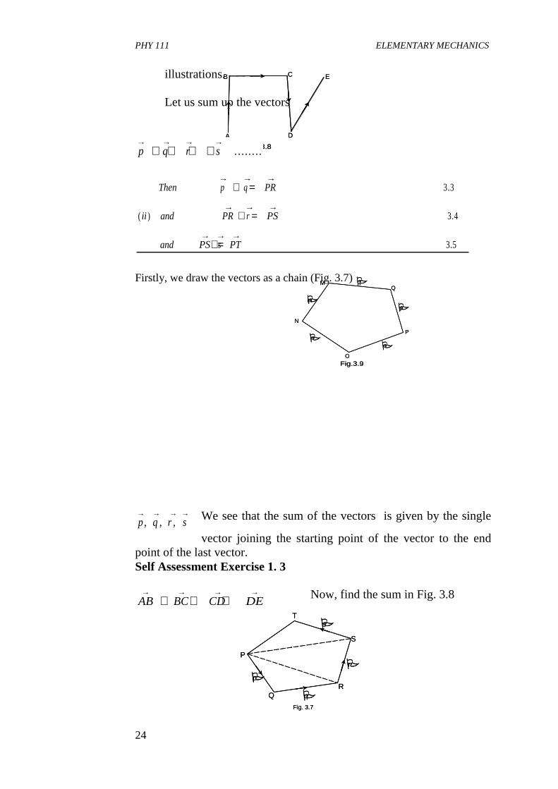
illustrations. Let us sum up the vectors
Firstly, we draw the vectors as a chain (Fig. 3.7)
We see that the sum of the vectors is given by the single
vector joining the starting point of the vector to the end point of the last vector. Self Assessment Exercise 1. 3
Now, find the sum in Fig. 3.8
p q r s→ → → →
+ + + + . ..... ..
Then p q PR
ii and PR r PS
and PS s PT
→ → →
→ → →
→ → →
+ =
+ =
+ =
3 3
3 4
3 5
.
( ) .
.
p q r s→ → → →
, , ,
AB BC CD DE→ → → →
+ + +
PHY 111 ELEMENTARY MECHANICS
25
Fig.3.10
b c
a(b)
� �
�Fig.3.10
b c
a(b)
� �
�
a b
a b
(a) Commutative law
��
� �
a b
a b
(a) Commutative law
��
� �
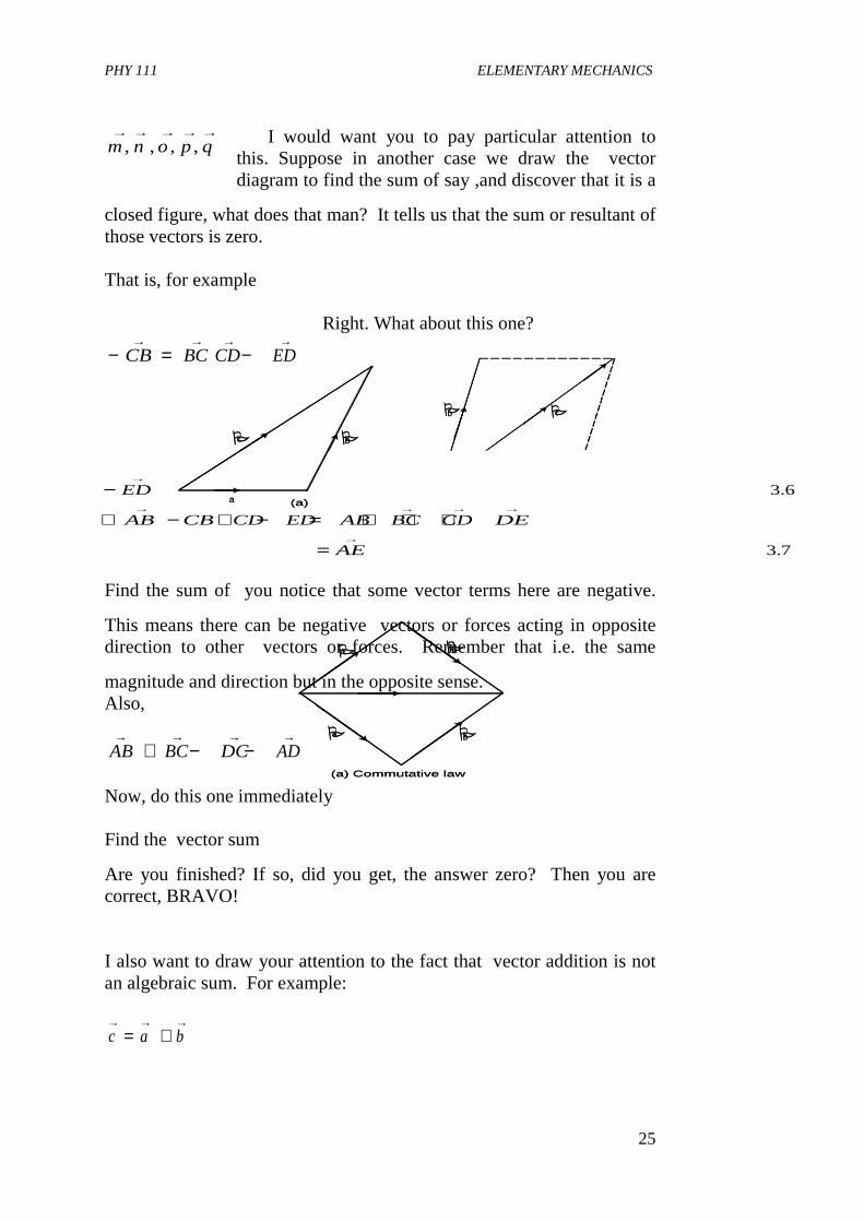
I would want you to pay particular attention to this. Suppose in another case we draw the vector diagram to find the sum of say ,and discover that it is a
closed figure, what does that man? It tells us that the sum or resultant of those vectors is zero. That is, for example
Right. What about this one?
Find the sum of you notice that some vector terms here are negative.
This means there can be negative vectors or forces acting in opposite direction to other vectors or forces. Remember that i.e. the same
magnitude and direction but in the opposite sense. Also,
Now, do this one immediately Find the vector sum
Are you finished? If so, did you get, the answer zero? Then you are correct, BRAVO! I also want to draw your attention to the fact that vector addition is not an algebraic sum. For example:
m n o p q, , , ,→ → → → →
AB CB CD ED→ → → →
− + −− =→ →
CB BC
− =
∴ − + − = + + +
=
→ →
→ → → → → → → →
→
ED DE
AB CB CD ED AB BC CD DE
AE
3 6
3 7
.
.
AB BC DC AD→ → → →
+ − −
c a b→ → →
= +
c b
a (a)
� �c b
a (a)
� �
PHY 111 ELEMENTARY MECHANICS
26
a
-a
-2a
2a
��
��a
-a
-2a
2a
��
��
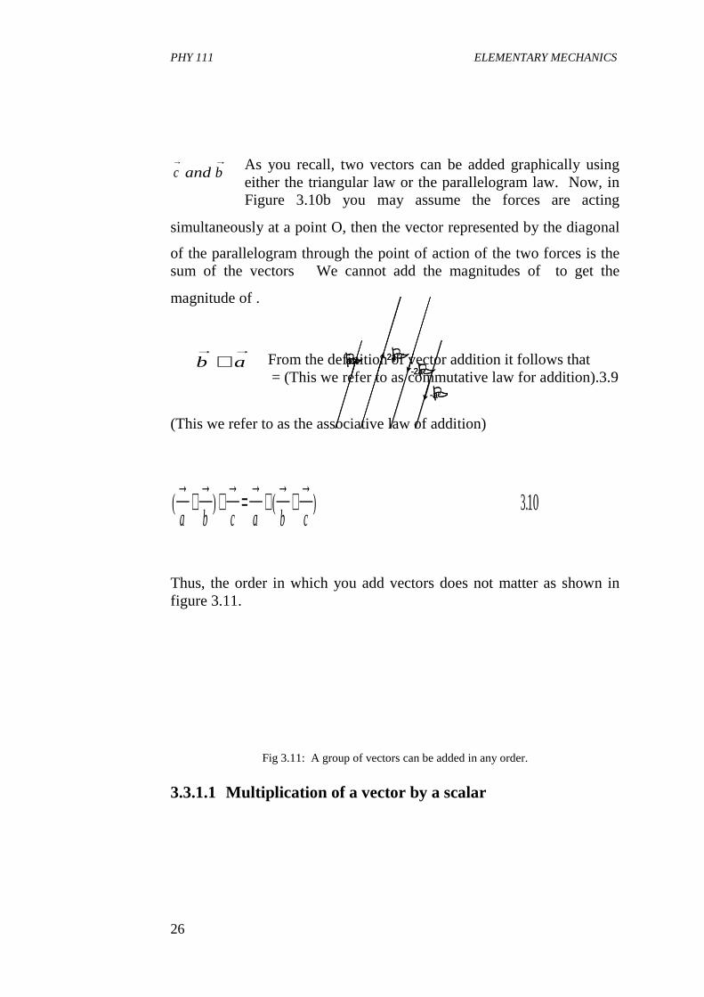
As you recall, two vectors can be added graphically using either the triangular law or the parallelogram law. Now, in Figure 3.10b you may assume the forces are acting
simultaneously at a point O, then the vector represented by the diagonal
of the parallelogram through the point of action of the two forces is the sum of the vectors We cannot add the magnitudes of to get the
magnitude of .
From the definition of vector addition it follows that = (This we refer to as commutative law for addition).3.9
(This we refer to as the associative law of addition)
Thus, the order in which you add vectors does not matter as shown in figure 3.11.
Fig 3.11: A group of vectors can be added in any order.
3.3.1.1 Multiplication of a vector by a scalar
a and b→ →c→a and b→ →a andb→ →c→
b a→ →
+
( ) ( ) .→
+→
+→
=→
+→
+→
a b c a b c310
PHY 111 ELEMENTARY MECHANICS
27
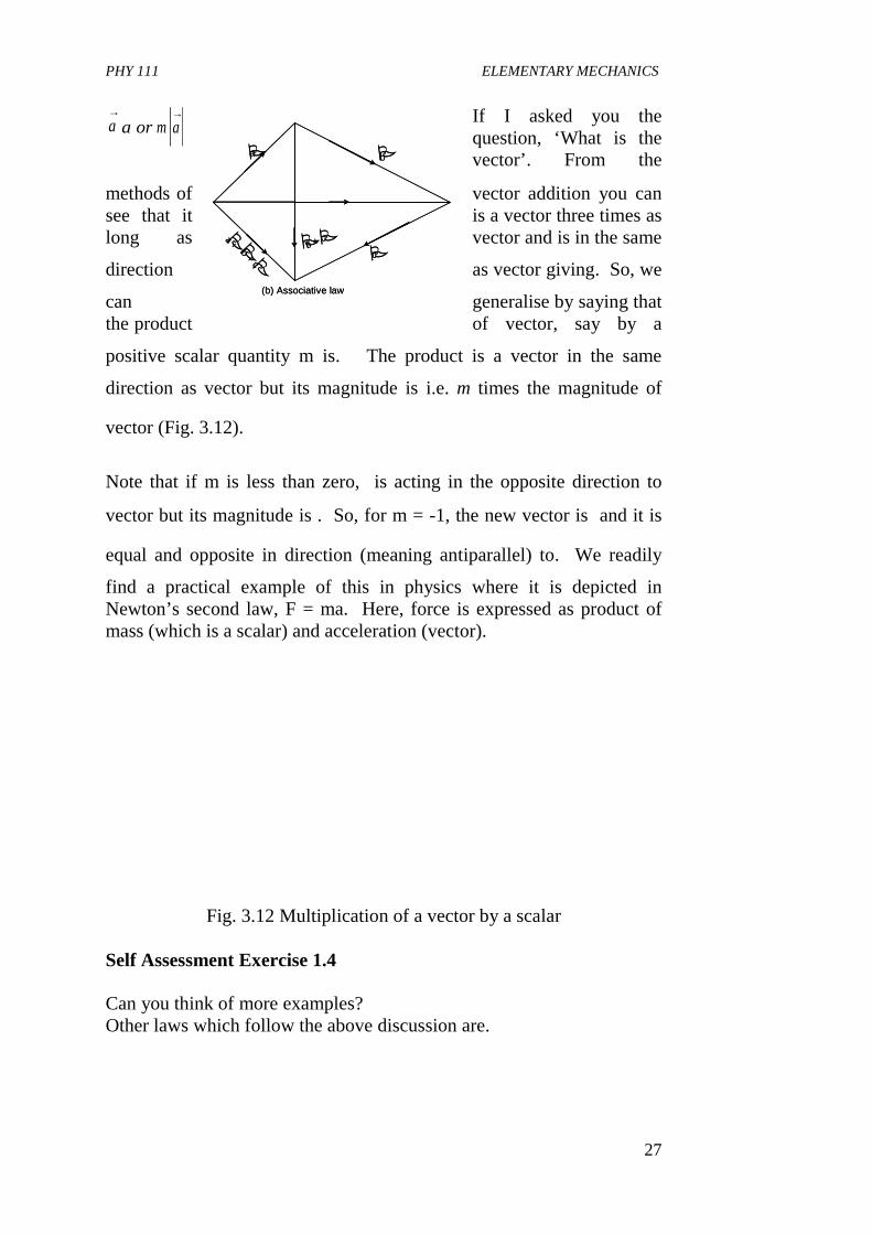
m a→
a→ If I asked you the
question, ‘What is the vector’. From the
methods of vector addition you can see that it is a vector three times as long as vector and is in the same
direction as vector giving. So, we
can generalise by saying that the product of vector, say by a
positive scalar quantity m is. The product is a vector in the same
direction as vector but its magnitude is i.e. m times the magnitude of
vector (Fig. 3.12).
Note that if m is less than zero, is acting in the opposite direction to
vector but its magnitude is . So, for m = -1, the new vector is and it is
equal and opposite in direction (meaning antiparallel) to. We readily
find a practical example of this in physics where it is depicted in Newton’s second law, F = ma. Here, force is expressed as product of mass (which is a scalar) and acceleration (vector).
Fig. 3.12 Multiplication of a vector by a scalar Self Assessment Exercise 1.4 Can you think of more examples? Other laws which follow the above discussion are.
b + c
a +
�
ba
cb + c
(b) Associative law
��
�����
b + c
a +
�
ba
cb + c
(b) Associative law
��
�����
a a a→ → →
+ +a→a→3a→a→m a
→
maor m a→
a→
PHY 111 ELEMENTARY MECHANICS
28
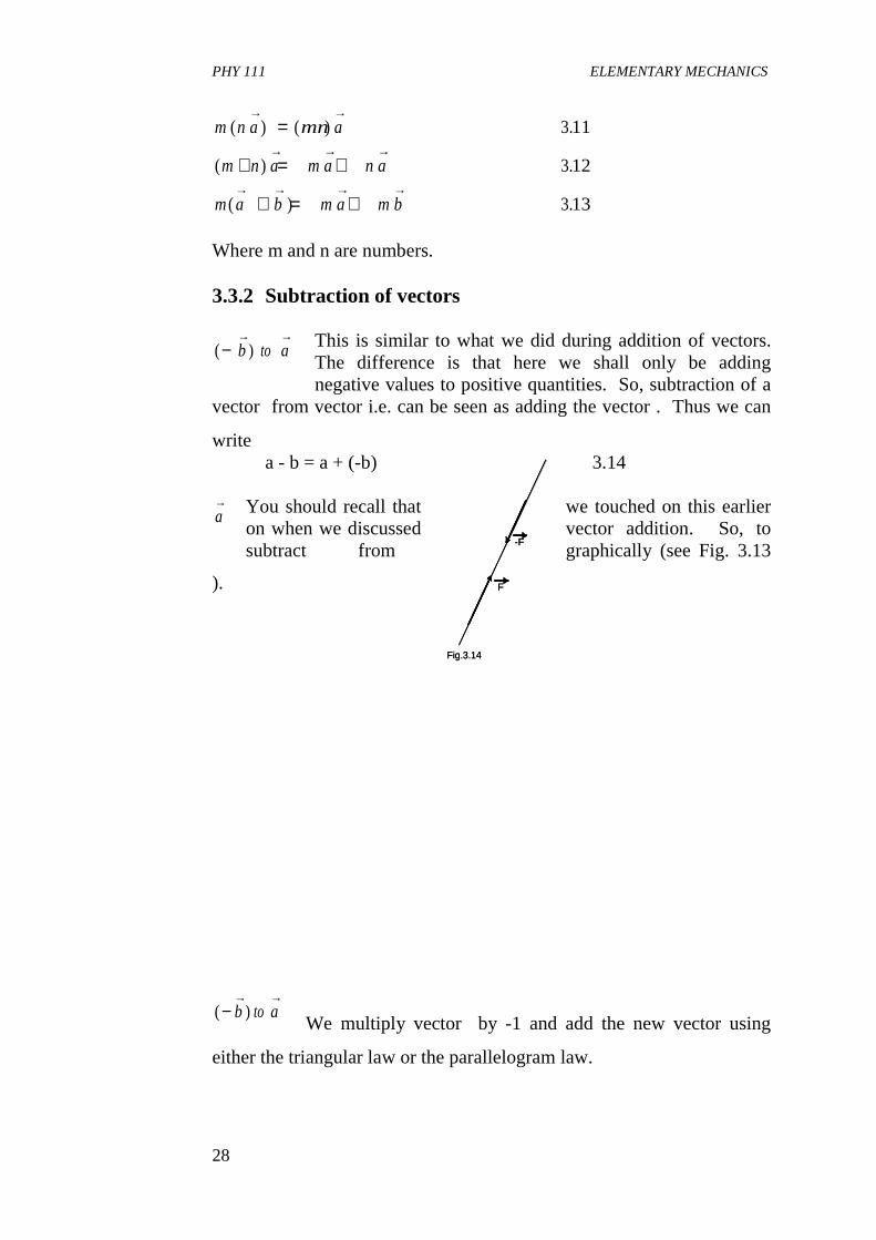
Where m and n are numbers. 3.3.2 Subtraction of vectors
This is similar to what we did during addition of vectors. The difference is that here we shall only be adding negative values to positive quantities. So, subtraction of a
vector from vector i.e. can be seen as adding the vector . Thus we can
write a - b = a + (-b) 3.14
You should recall that we touched on this earlier on when we discussed vector addition. So, to subtract from graphically (see Fig. 3.13
).
We multiply vector by -1 and add the new vector using
either the triangular law or the parallelogram law.
m n a mna
m n a m a n a
m a b m a m b
( ) ( ) .
( ) .
( ) .
→ →
→ → →
→ → → →
=
+ = +
+ = +
311
312
313
b→a→a b→ →
−( )−→ →b to a
b→a→
b→( )−
→ →b to a
-F
F
Fig.3.14
-F
F
Fig.3.14
PHY 111 ELEMENTARY MECHANICS
29
a
( a – b )
-b
b
Fig. 3.13
�
���
�
a
( a – b )
-b
b
Fig. 3.13
�
���
�
a
a
→
3.3.2.1 The Null Vector
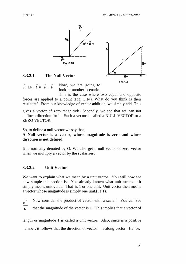
Now, we are going to look at another scenario. This is the case where two equal and opposite
forces are applied to a point (Fig. 3.14). What do you think is their resultant? From our knowledge of vector addition, we simply add. This
gives a vector of zero magnitude. Secondly, we see that we can not define a direction for it. Such a vector is called a NULL VECTOR or a ZERO VECTOR. So, to define a null vector we say that, A Null vector is a vector, whose magnitude is zero and whose direction is not defined. It is normally denoted by O. We also get a null vector or zero vector when we multiply a vector by the scalar zero. 3.3.2.2 Unit Vector We want to explain what we mean by a unit vector. You will now see how simple this section is. You already known what unit means. It simply means unit value. That is 1 or one unit. Unit vector then means a vector whose magnitude is simply one unit.(i.e.1).
Now consider the product of vector with a scalar You can see
that the magnitude of the vector is 1. This implies that a vector of
length or magnitude 1 is called a unit vector. Also, since is a positive
number, it follows that the direction of vector is along vector. Hence,
F F F F→ → → →
+ − = −( )
a→1
aa
a
→1
aa
a
→a→
Xè
O C
DP
a
b
Y
Fig.3.16
r
�
�X
èO C
DP
a
b
Y
Fig.3.16
r
�
�è
O C
DP
a
b
Y
Fig.3.16
r
�
�
PHY 111 ELEMENTARY MECHANICS
30
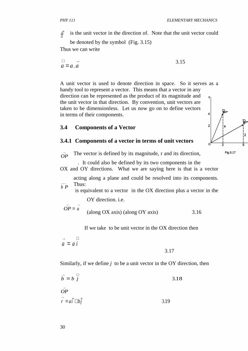
is the unit vector in the direction of. Note that the unit vector could
be denoted by the symbol (Fig. 3.15) Thus we can write
3.15
A unit vector is used to denote direction in space. So it serves as a handy tool to represent a vector. This means that a vector in any direction can be represented as the product of its magnitude and the unit vector in that direction. By convention, unit vectors are taken to be dimensionless. Let us now go on to define vectors in terms of their components. 3.4 Components of a Vector 3.4.1 Components of a vector in terms of unit vectors
The vector is defined by its magnitude, r and its direction,
�. It could also be defined by its two components in the OX and OY directions. What we are saying here is that is a vector
acting along a plane and could be resolved into its components. Thus: is equivalent to a vector in the OX direction plus a vector in the
OY direction. i.e. (along OX axis) (along OY axis) 3.16
If we take to be unit vector in the OX direction then
3.17 Similarly, if we define j to be a unit vector in the OY direction, then
a→$a
a a a∧ →
= .
OP→
OP→
OP→
a→b→
OP a→ →
=
a a i→ ∧
=
b b j→ ∧
= 318.
OP→
r ai bj→
= +$ $ .319
O
4 a
b
Y
Fig.3.17
2
2
4
2 5
�
�
O
4 a
b
Y
Fig.3.17
2
2
4
2 5
�
�
PHY 111 ELEMENTARY MECHANICS
31
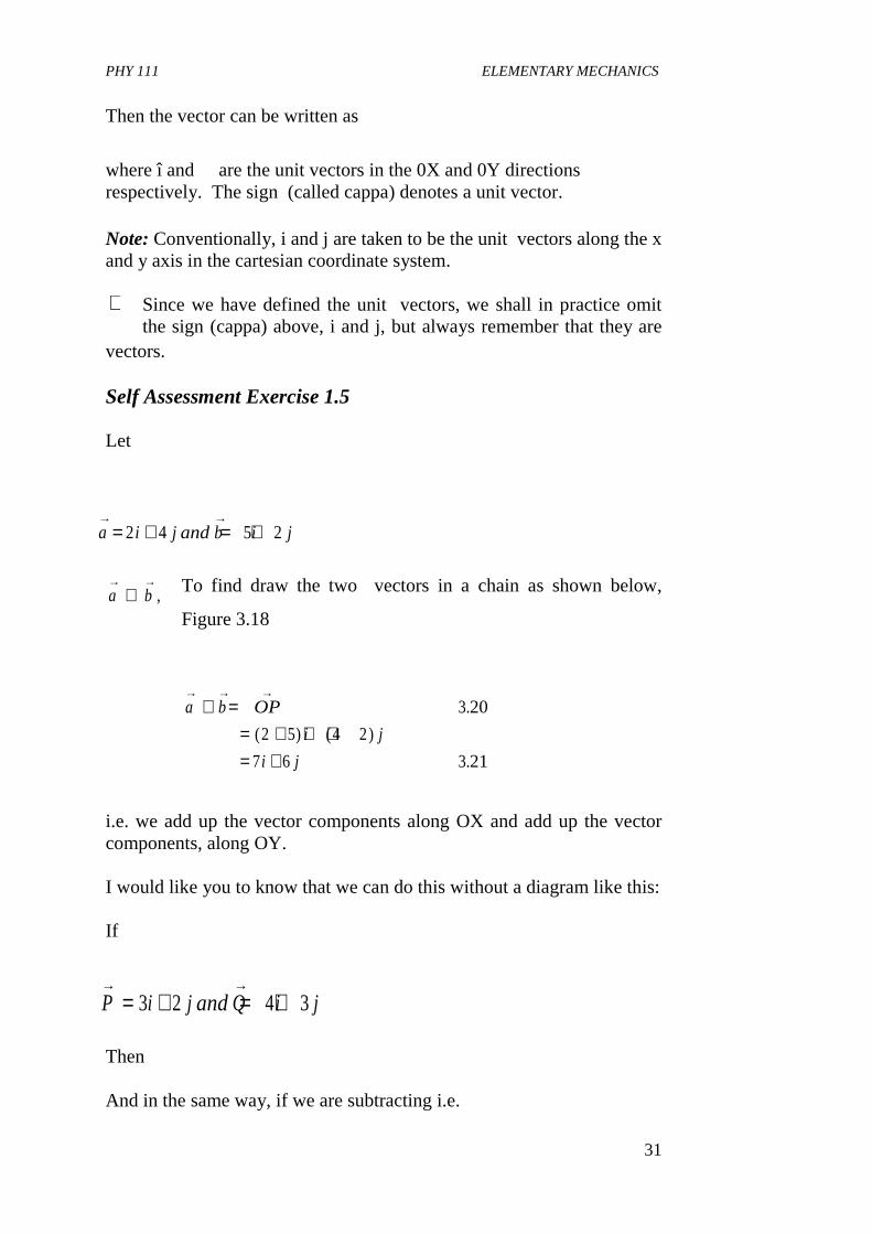
Then the vector can be written as
where î and � are the unit vectors in the 0X and 0Y directions respectively. The sign (called cappa) denotes a unit vector. Note: Conventionally, i and j are taken to be the unit vectors along the x and y axis in the cartesian coordinate system.
Since we have defined the unit vectors, we shall in practice omit the sign (cappa) above, i and j, but always remember that they are
vectors. Self Assessment Exercise 1.5 Let
To find draw the two vectors in a chain as shown below,
Figure 3.18
i.e. we add up the vector components along OX and add up the vector components, along OY. I would like you to know that we can do this without a diagram like this: If
Then And in the same way, if we are subtracting i.e.
∧
a i j andb i j→ →
= + = +2 4 5 2
a b→ →
+ ,
a b OP
i j
i j
→ → →+ =
= + + += +
3 20
2 5 4 2
7 6 321
.
( ) ( )
.
P i j andQ i j→ →
= + = +3 2 4 3
PHY 111 ELEMENTARY MECHANICS
32
èO C
DP
X
Y
Fig. 3.19
r
èO C
DP
X
Y
Fig. 3.19
r
Similarly if
Then,
Self Assessment Exercise 1.6
(i)
(ii)
Complete the working above. Your answers should be (i) 12i (ii) -2i - 4j Compare your solution with these
3.4.2 Component of a Vector in Terms of Polar Coordinates
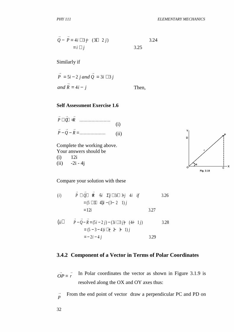
In Polar coordinates the vector as shown in Figure 3.1.9 is
resolved along the OX and OY axes thus: From the end point of vector draw a perpendicular PC and PD on
Q P i j i j
i j
→ →− = + − +
= +4 3 3 2 324
3 25
( ) .
.
P i j andQ i j
andR i j
→ →
→
= − = +
= −
5 2 3 3
4
P Q R→ → →
+ + = . .. .. .. .. . .. .. .. .. .. . ..
P Q R→ → →
− − = . . . . . . . . . . . . . . . . . ..
( ) .
(5 ) ( )
.
i P Q R i j i j i if
i j
i
→ → →+ + = − + + + −
= + + + − −=
5 2 3 3 4 326
3 4 3 2 1
12 3 27
( )ii P Q R i j i j i j
i j
i j
→ → →− − = − − + − −
= − − + − − −= − −
(5 ) ( ) ( ) .
(5 ) ( )
.
2 3 3 4 1 328
3 4 2 3 1
2 4 329
OP r→ →
=
p→
PHY 111 ELEMENTARY MECHANICS
33
X and Y-axes respectively. Then, OC and OD represent the resolved parts of the vector in magnitude and direction. Hence we have
OC = OP Cos 2 = r Cos 2 ....3.30
OD = OP Sin 2 = r Sin 2 .... 3.31
and OC2 + OD2 = OP2= r2 (Cos22 + Sin22) = r2 ...... 3.32
Now, are the components of vector in
polar coordinates. 4.0 CONCLUSION What you have learnt in this unit concerns • Definition and representation of vectors • How vectors are denoted • Composition of vectors • How to resolve vectors into their components in two dimensional
space • How to express vectors in terms of their unit vectors 5.0 SUMMARY In this unit you have learnt that:- • Quantities which are completely specified by a number are called
scalars with a suitable choice of units. • Vectors are quantities which are specified by a positive real
number called magnitude or modulus and have a direction in space.
• Vectors combine according to the following rules
• Any vector can be expressed as
OC r Cos andOD r Sin→ →
= =θ θOP→
a b b a
a b a a b a
m n a mna
m n a m a n a
m a b m a m b
→ → → →
→ → → → → →
→ →
→ → →
→ → → →
+ = +
+ + = + +
=
+ = +
+ = +
( ) ( )
( ) ( )
( )
( )
a→
PHY 111 ELEMENTARY MECHANICS
34
• Where is a unit vector in the direction of
• Vectors can be expressed in terms of unit vectors along the X and Y
axes of a plane Cartesian coordinate system. Thus the unit vectors i, j point along the X and Y- axes respectively. Then for a vector.
The quantities Vx, Vy are the components of. The magnitude of V is
• The NULL vector is the vector of zero magnitude and unspecified
direction 6.0 TUTOR MARKED ASSIGNMENTS 1. Let V be the wind velocity of 50km h-1 from north-east. Write
down the vector representing a wind velocity of (i) 75 kmh-1 from north-east (ii) 100km h-1 from south-west in terms of V. Answers; to question 1 are:
2. Let i and j denote unit vectors in the directions of east and north, respectively. Specify the following vectors in terms of i and j (i) The displacement of persons going from point A to point
B (about 2300km due south) and from point A to point C (1700km due east).
Answers to question 2 are:
a a→
= $α
$aa→
∨→
V V i V jx y
→= +
V→
V V Vx y= +2 2
( )
( )
i V
ii V
3
22−
PHY 111 ELEMENTARY MECHANICS
35
1. -2300j 2. 1700i 7.0 REFERENCES AND FURTHER READING Spiegel, M. R. (1959). Vector Analysis-Schaum’s Series, McGraw-Hill
Book Company, New York. Stroud, K. A. (1995). Engineering Mathematics-Fourth Edition London.
Macmillian Press Ltd. Das Sarma, J.M. (1978). An Introduction to Higher Secondary Physics.
India, modern Book Agency Private Ltd. Fishbane, P. M.; Gasiorowicz, S. and Thronton, S. T., (1996). Physics
for Scientist and Engineers 2rd Ed. Vol. 1. New Jersey, Practice Hall.
UNIT 4 VECTORS IN THREE DIMENSIONS CONTENTS 1.0 Introduction 2.0 Objectives 3.0 Main Body
3.1 Vector in Space 3.1.1 Magnitude of a Vector in Space 3.1.2 Resolution of Vectors in Three
Mutually Perpendicular Axes 3.1.3 Resolution of Vectors in Terms of Unit Vectors in
Three Mutually Perpendicular Axes 3.2 Vector Product
3.2.1 Scalar (or Dot) Product 3.2.2 Vector (or Cross) Product 4.0 Conclusion 5.0 Summary 6.0 Teacher Marked Assignments (TMAs) and marking scheme 7.0 References and Further Reading
PHY 111 ELEMENTARY MECHANICS
36
1.0 INTRODUCTION The importance of vectors in physics cannot be over emphasised. This is because most physical quantities we come across in physics are vector quantities. These include electric flows, magnetic flux, forces, velocities, etc. Also, we recall that in unit 2 we discovered that every object in the universe is in constant motion. Since it is one kind of force or the other that keeps these objects in motion, and motion could be in one, two or three dimensions and force is a vector. It is important to study vectors in all these dimensions. By so doing we get an understanding of why certain occurrences in nature behave as they do. In this Unit, therefore, we shall dwell on vector in space, resolution of vectors I three dimensions. You will also learn about vector product. 2.0 OBJECTIVES By the end of this Unit you should be able to: • Write the general equation that gives the magnitude of a vector in
space • Resolve a vector in space along three mutually perpendicular axes • Resolve a vector in terms of its Unit vectors along three mutually
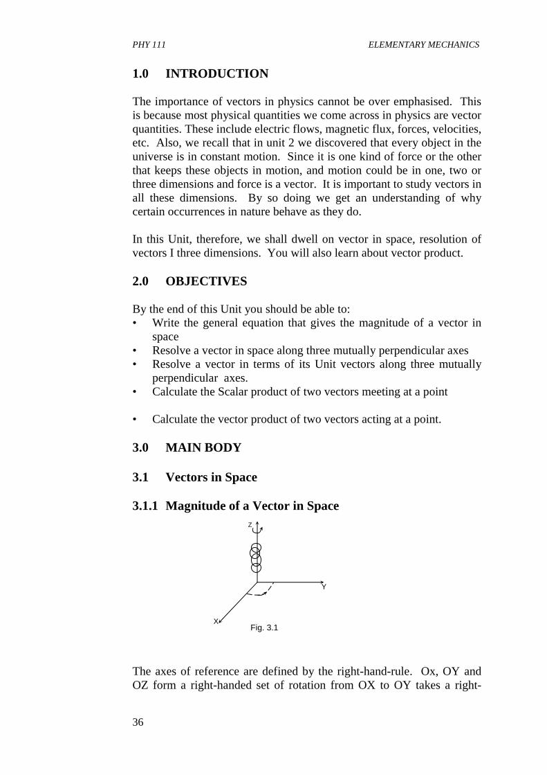
perpendicular axes. • Calculate the Scalar product of two vectors meeting at a point • Calculate the vector product of two vectors acting at a point. 3.0 MAIN BODY 3.1 Vectors in Space 3.1.1 Magnitude of a Vector in Space The axes of reference are defined by the right-hand-rule. Ox, OY and OZ form a right-handed set of rotation from OX to OY takes a right-
Z
Y
X Fig. 3.1
PHY 111 ELEMENTARY MECHANICS
37
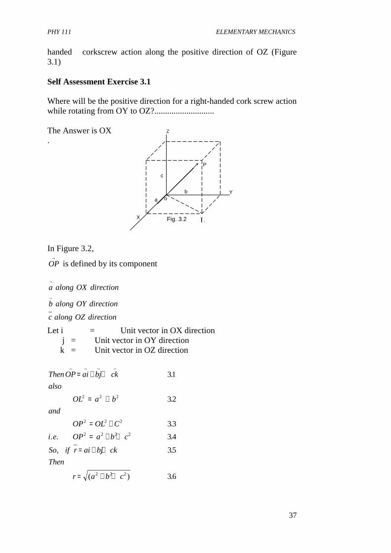
handed corkscrew action along the positive direction of OZ (Figure 3.1) Self Assessment Exercise 3.1 Where will be the positive direction for a right-handed cork screw action while rotating from OY to OZ?............................ The Answer is OX . In Figure 3.2,
OP→
is defined by its component
a along OX direction
b along OY direction
c along OZ direction
→
→
Let i = Unit vector in OX direction j = Unit vector in OY direction k = Unit vector in OZ direction
ThenOP ai bj ck
also
OL a b
and
OP OL C
i e OP a b c
So if r ai bj ck
Then
r a b c
→ → → →= + +
= +
= +
= + +
= + +
= + +
31
32
33
34
35
36
2 2 2
2 2 2
2 2 2 2
2 2 2
.
.
.
. . .
, .
( ) .
L
o
Z
Y
X Fig. 3.2
P
b
c
a
PHY 111 ELEMENTARY MECHANICS
38
The value of r here gives the magnitude of the vector OP→
in Figure 3.2. This is also an easy way of finding the magnitude of a vector when it is expressed in terms of its Unit vectors. Self Assessment Exercise 3.2 Now you can do this one
If PQ i j k then PQ
Theanswer is PQ
→
→
= + + =
= =
4 3 2
29 5385
, / / ?
( ) .
This is how to solve it. We are given that
| | .
| | ( .
( ) ( ) .
.
PQ i j k
PQ
Answer
→
→
= + +
∴ = + +
= + + ==
4 3 2 37
4 3 2 38
16 9 4 29 39
5385
2 2 2
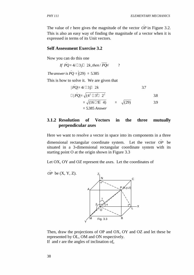
3.1.2 Resolution of Vectors in the three mutually
perpendicular axes Here we want to resolve a vector in space into its components in a three
dimensional rectangular coordinate system. Let the vector →
OP be situated in a 3-dimensional rectangular coordinate system with its starting point O at the origin shown in Figure 3.3 Let OX, OY and OZ represent the axes. Let the coordinates of
→
OP be (X, Y, Z). Then, draw the projections of OP and OX, OY and OZ and let these be represented by OL, OM and ON respectively. If and r are the angles of inclination of,
P (x,y,z) A
Z N C
O
B M Y
X L
β α
γ
Fig. 3.3
PHY 111 ELEMENTARY MECHANICS
39
→OP with OX, OY and OZ axes respectively, then, OP Cos A= x 3.10 OP Cos = y 3.11 And OP Cos r = z 3.12 OP�2 (Cos2 + Cos2 + Cos2 r) = x2 + y2 + 22 3.13 But we know that OP2 = OL2 + OM2 + ON2 = x2 + y2 + 22 3.14 Cos2 + Cos2 + Cos2 r = l2 + m2 + n2 = 1 3.15 where l, m, n are called the direction cosines.
Alsoopx
OP
y
OP
z
OP
x
OPx
y
OPy
z
OPz
Cos x Cos y Cosrz
lx my nz
= + + = + +
= + += + +
2 2 2
316
317
318
. . . .
.
.
α β
Thus the vector OP can be complete resolved in magnitude by the coordinate of its starting point (O, O, O) and end point (X, Y, Z) and in direction by the three direction cosines (l, m, n). Now considering the case when the vector lies in a plane, say the XOY plane, then Z = 0 and we get that OP = lx + my 3.19 it follows also that for a vector lying in the XOZ plane, then y = 0 and for a vector lying in the YOZ plane, x = 0 3.1.3 Resolution of Vectors in Three Mutually perpendicular
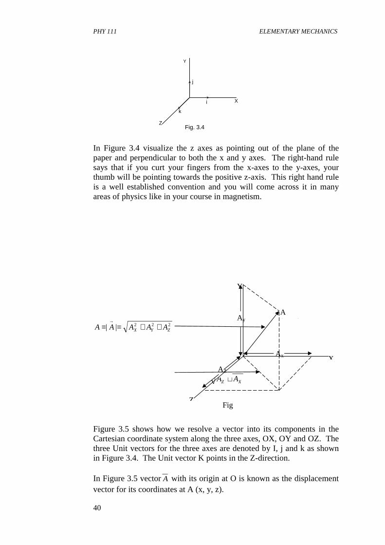
axes in terms of the Unit Vectors The vectors we have considered thus far are two dimensional and Unit vectors in three dimensions. Now, let us generalise for any vector in three dimensional system. This is same as considering a vector in space. A vector in three dimensions can be specified with Cartesian set of axes x, y and z as we discussed earlier in this Unit. The orientation of the axes is best described using the right -hand rule.
PHY 111 ELEMENTARY MECHANICS
40
In Figure 3.4 visualize the z axes as pointing out of the plane of the paper and perpendicular to both the x and y axes. The right-hand rule says that if you curt your fingers from the x-axes to the y-axes, your thumb will be pointing towards the positive z-axis. This right hand rule is a well established convention and you will come across it in many areas of physics like in your course in magnetism.
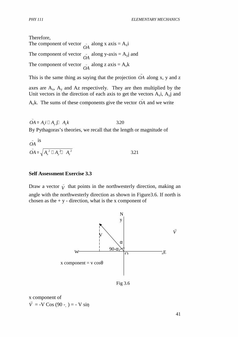
222|| ZYX AAAAA ++==→
XZ AA + Figure 3.5 shows how we resolve a vector into its components in the Cartesian coordinate system along the three axes, OX, OY and OZ. The three Unit vectors for the three axes are denoted by I, j and k as shown in Figure 3.4. The Unit vector K points in the Z-direction. In Figure 3.5 vectorA with its origin at O is known as the displacement vector for its coordinates at A (x, y, z).
Y
X
Z Fig. 3.4
j
i
k
Ax
A (x,y,z) Ay
Y
X
Z
AZ
Fig 3.5
PHY 111 ELEMENTARY MECHANICS
41
Therefore, The component of vector
OA→ along x axis = Axi
The component of vector OA
→ along y-axis = Ayj and
The component of vector OA
→ along z axis = Azk
This is the same thing as saying that the projection
→OA along x, y and z
axes are Ax, Ay and Az respectively. They are then multiplied by the Unit vectors in the direction of each axis to get the vectors Axi, Ayj and
Azk. The sums of these components give the vector →
OA and we write
OA A i A j A kx y z
→= + + 320.
By Pythagoras’s theories, we recall that the length or magnitude of
OA→ is
OA A A Ax y z
→= + +2 2 2 321.
Self Assessment Exercise 3.3 Draw a vector V
→ that points in the northwesterly direction, making an
angle with the northwesterly direction as shown in Figure3.6. If north is chosen as the + y - direction, what is the x component of
r
V x component of r
V = -V Cos (90 - ) = - V sin
O W
V
N y
xE
α
90-α
x component = v cosθ
Fig 3.6
PHY 111 ELEMENTARY MECHANICS
42
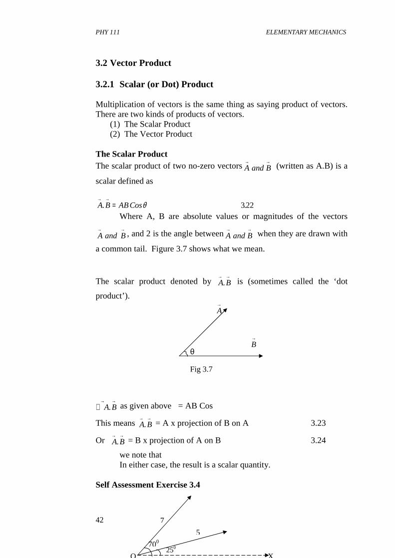
3.2 Vector Product 3.2.1 Scalar (or Dot) Product Multiplication of vectors is the same thing as saying product of vectors. There are two kinds of products of vectors.
(1) The Scalar Product (2) The Vector Product
The Scalar Product The scalar product of two no-zero vectorsA and B
→ → (written as A.B) is a
scalar defined as
A B ABCos→ →
=. .θ 322
Where A, B are absolute values or magnitudes of the vectors
A and B→ →
, and 2 is the angle betweenA and B→ →
when they are drawn with
a common tail. Figure 3.7 shows what we mean.
The scalar product denoted by A B→ →
. is (sometimes called the ‘dot
product’).
→A
→B
∴→ →A B. as given above�= AB Cos
This means A B→ →
. = A x projection of B on A 3.23
Or A B→ →
. = B x projection of A on B 3.24
we note that In either case, the result is a scalar quantity. Self Assessment Exercise 3.4
θ
Fig 3.7
7
O X
5
700 250
PHY 111 ELEMENTARY MECHANICS
43
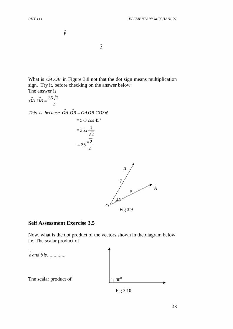
→B
→A
What is →→
OBOA. in Figure 3.8 not that the dot sign means multiplication sign. Try it, before checking on the answer below. The answer is
2
235. =
→→OBOA
2
235
2
135
45cos75
..0
=
=
==
→→
x
x
COSOBOAOBOAbecauseisThis θ
→B
→A
Self Assessment Exercise 3.5 Now, what is the dot product of the vectors shown in the diagram below i.e. The scalar product of
a and b is→ →
..............
The scalar product of
45
7
5
O Fig 3.9
900
Fig 3.10
PHY 111 ELEMENTARY MECHANICS
44
a and b a b→ → → →
= =. .0 326
This is so because
a b abCos→ →
=. .90 3270
but Cos 900 = 0 The scalar product of any two vectors at right angles to each other is always zero. What happens if the two vectors are in the (i) Same direction (ii) opposite direction. For example
→a
→a
→b
→b
In Figure 3.10 a vectors
a and b→ → are in the = 0�same direction, 0.
Then a b→ →
. = ab Cos 00 = a.b.1 = ab 3.28
In Fig 3.10b vectors a and b→ →
= 180�are in opposite direction, 0. Then
a b ab a b ab→ →
= = − = −. cos . .( )180 10
Self Assessment Exercise 3.6 When the vectors are expressed in terms their Unit vectors in component form of we have,
Then
A B a i b j c k a i b j c k→ →
= + + + +. ( ) .( ) .1 1 1 2 2 2 329
(a) (b)
Fig 3.10
A a i b j c k
B a i b j c k
→
→
= + +
= + +
1 1 1
2 2 2
PHY 111 ELEMENTARY MECHANICS
45
= + + + ++ + + +
a a i i a b i j a c i k b a j i
b b j j b c j k c a k i c b k i c c k k1 1 1 2 1 2 1 2
1 2 1 2 1 2 1 2 1 2 330
. . . .
. . . . . .
Just be careful when expending such brackets above. This will simplify soon, so no need to worry. Take note that i.i = 1.1. Cos 00 = 1 3.31 Similarly j.j = 1 and k.k = 1 always remember this. Now i.j = 1 Cos 900 = 0 3.32 We see that the following terms will also varnish i.e. j.k = 0 and k. i = 0 applying these in one expression for
A B→ →
. we have
A B a a b b c c→ →
= + +. .1 2 1 2 1 2 333
Since A B a a a b a c b a
b b c a c b o c c
.
.
= + + + ++ + +
1 2 1 2 1 2 1 1
1 2 1 2 1 2 1 2
1 0 0 0
1 0 1 334
hence we dropped the terms in zero to assure at our answer above Properties of dot Product
1. a b→ →
. is a scalar
2. a b→ →
. = b a→ →
. i.e. the dot product is commutative 3.35 3.
a b c a b a c→ → → → → → →
= +.( . ) . . i.e. the dot product is associative over addition
3.36 4.
( ). ( . ) .( ) .ma b m a b a mb→ → → → →
= = 337
5. If a b and a and b→ → → →
=. ,0 are not zero, vectors then, a is
perpendicular to b 3.38 6.
a a a a→
= =2 339. .
7. a a→ →
>. 0 For any non zero vector
a
8. a a→ →
=. 0 only if a = 0 3.40
PHY 111 ELEMENTARY MECHANICS
46
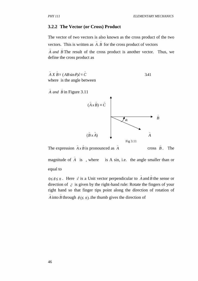
3.2.2 The Vector (or Cross) Product The vector of two vectors is also known as the cross product of the two
vectors. This is written as →→BA. for the cross product of vectors
→→BandA The result of the cross product is another vector. Thus, we
define the cross product as
A X B AB c C→ → →
= =( sin )$ .θ 341
where is the angle between�
→→BandA in Figure 3.11
→→→
= CBxA )(
→B
)(→→AxB
→A
The expression →→BxA is pronounced as
→A cross
→B . The
magnitude of →A is�, where � is A sin, i.e.�the angle smaller than or
equal to
0≤ ≤θ π . Here ĉ is a Unit vector perpendicular to →Aand
→B the sense or
direction of ĉ is given by the right-hand rule: Rotate the fingers of your right hand so that finger tips point along the direction of rotation of →A into
→B through θ π( )≤ .the thumb gives the direction of
θ
Fig 3.11
PHY 111 ELEMENTARY MECHANICS
47
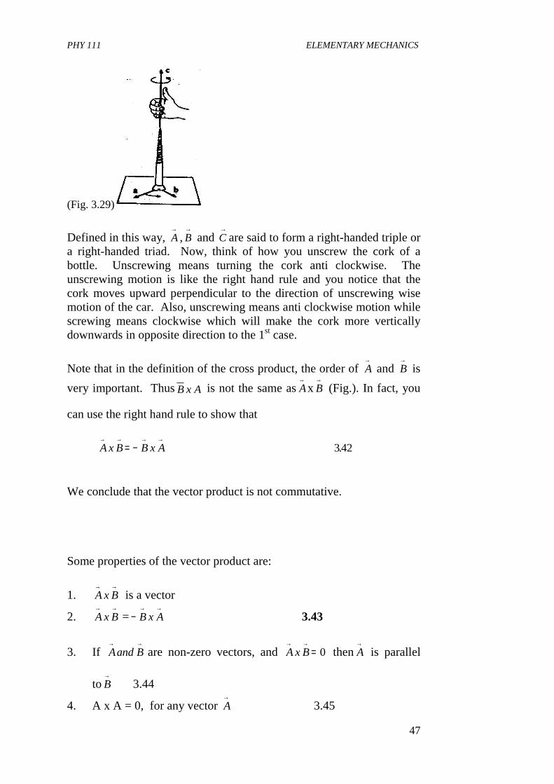
(Fig. 3.29)
Defined in this way, →A ,
→B and
→C are said to form a right-handed triple or
a right-handed triad. Now, think of how you unscrew the cork of a bottle. Unscrewing means turning the cork anti clockwise. The unscrewing motion is like the right hand rule and you notice that the cork moves upward perpendicular to the direction of unscrewing wise motion of the car. Also, unscrewing means anti clockwise motion while screwing means clockwise which will make the cork more vertically downwards in opposite direction to the 1st case.
Note that in the definition of the cross product, the order of A→
and B→
is
very important. ThusB x A is not the same asA→
x B→
(Fig.). In fact, you
can use the right hand rule to show that
We conclude that the vector product is not commutative. Some properties of the vector product are:
1. A x B→ →
is a vector
2. A x B→ →
= −→ →B x A 3.43
3. If Aand B→ →
are non-zero vectors, and A x B→ →
= 0 thenA→
is parallel
toB→
3.44
4. A x A = 0, for any vector A→
3.45
A x B B x A→ → → →
= − 342.
PHY 111 ELEMENTARY MECHANICS
48
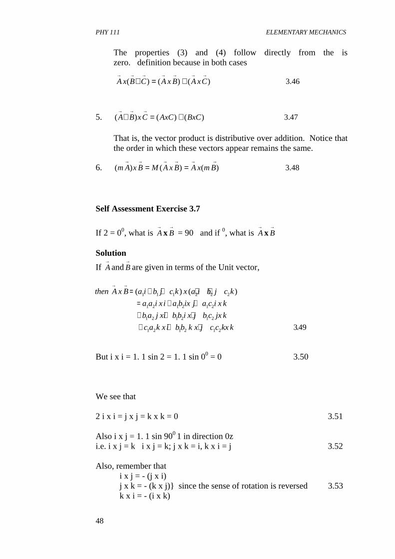
The properties (3) and (4) follow directly from the is zero.�definition because in both cases
46.3)()()(→→→→→→→
+=+ CxABxACBxA
5. 47.3)()()( BxCAxCCxBA +=+→→→
That is, the vector product is distributive over addition. Notice that the order in which these vectors appear remains the same.
6. 48.3)()()(→→→→→→
== BmxABxAMBxAm
Self Assessment Exercise 3.7
If 2 = 00, what is →Ax
→B = 90�and if 0, what is
→Ax
→B
Solution
If →Aand
→B are given in terms of the Unit vector,
But i x i = 1. 1 sin 2 = 1. 1 sin 00 = 0 3.50 We see that 2 i x i = j x j = k x k = 0 3.51 Also i x j = 1. 1 sin 900 1 in direction 0z i.e. i x j = k i x j = k; j x k = i, k x i = j 3.52 Also, remember that i x j = - (j x i) j x k = - (k x j)} since the sense of rotation is reversed 3.53 k x i = - (i x k)
then A x B a i b j c k x a i b j c k
a a i x i a b ix j a c i x k
b a j xi b b i x j b c jx k
c a k x i b b k x j c c kx k
→ →= + + + +
= + ++ + ++ + +
( ) ( )
.
1 1 1 2 2 2
1 2 1 2 1 2
1 2 1 2 1 2
1 2 1 2 1 2 349
PHY 111 ELEMENTARY MECHANICS
49
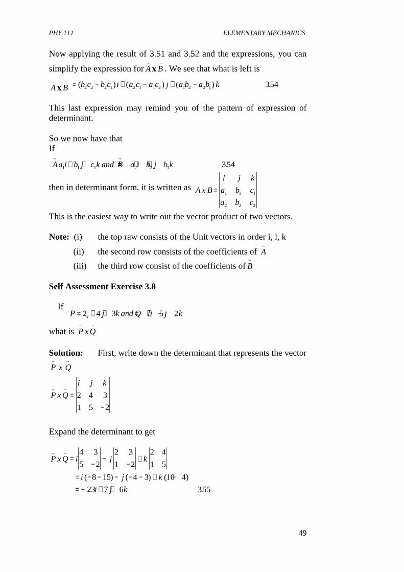
Now applying the result of 3.51 and 3.52 and the expressions, you can
simplify the expression for→Ax
→B . We see that what is left is
→Ax
→B = − + − + −( ) ( ) ( ) .b c b c i a c a c j a b a b k2 2 2 1 2 1 1 2 1 2 2 1 354
This last expression may remind you of the pattern of expression of determinant. So we now have that If
Aa i b j c k and B a i b j b k→ →
+ + = + +1 1 1 2 2 1 354.
then in determinant form, it is written as A x B
l j k
a b c
a b c
= 1 1 1
2 2 2
This is the easiest way to write out the vector product of two vectors. Note: (i) the top raw consists of the Unit vectors in order i, l, k
(ii) the second row consists of the coefficients of →A
(iii) the third row consist of the coefficients of B→
Self Assessment Exercise 3.8 If
P j k and Q li j kl
→ →= + + = + −2 4 3 5 2
what is P x Q→ →
Solution: First, write down the determinant that represents the vector
P x Q→ →
P xQ
i j k→ →
=−
2 4 3
1 5 2
Expand the determinant to get
P x Q i j k
i j k
i j k
→ →=
−−
−+
= − − − − − + −= − + +
4 3
5 2
2 3
1 2
2 4
1 5
8 15 4 3 10 4
23 7 6 355
( ) ( ) ( )
.
PHY 111 ELEMENTARY MECHANICS
50
Finally, note that the result of the cross product of two vectors is a vector quantity. You should always remember this property of vector product. 4.0 CONCLUSION What you have learnt in this Unit concerns • the determination of the magnitude of a vector in space. • how to resolve a vector into its components in three mutually
perpendicular axes. • the determination of the direction cosines of a vector • the resolution of vectors in terms of their Unit vectors • the determination of the scalar (dot) product • the determination of the vector (cross) product of two vectors 5.0 SUMMARY In this Unit, you have learnt that
• For vectors A and B→ →
their magnitude and direction can be expressed in terms of their components and Unit vectors in three-dimensional Cartesian coordinate system as
A a i a j a k
A A a a aa
a
B b i b j b k
B B b b b
→
→
= + +
= = + + =
= + +
= = + +
1 2 3
12
22
32 2
1
1 2 3
12
22
32
, tanθ
The direction cosines (l, m, n) for B
→ , say, is
l
b
Bm
b
Band
n rb
B
= = = =
= =
cos , cos
cos
1 2
3
β
Here, ai and bi are the components of A and B→ →
. And i, j, k are the Unit
vectors along the positive x, y and z axes. Here also, angleA→ makes
with x-axis. A and B are the angles, , And B→ makes with the x, y and
z-axes respectively. • The scalar product of two vectors are defined as
PHY 111 ELEMENTARY MECHANICS
51
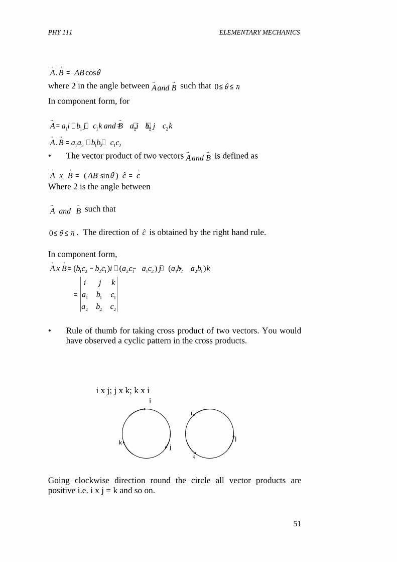
A B AB→ →
=. cosθ
where 2 in the angle betweenAand B→ →
such that 0≤ ≤θ π
In component form, for
A a i b j c k and B a i b j c k
A B a a b b c c
→ →
→ →
= + + = + +
= + +
1 1 1 2 2 2
1 2 1 2 1 2.
• The vector product of two vectorsAand B→ →
is defined as
A x B AB c c→ → →
= =( sin ) $θ
Where 2 is the angle between
A and B→ →
such that
0≤ ≤θ π . The direction of $c is obtained by the right hand rule. In component form,
A x B b c b c i a c a c j a b a b k
i j k
a b c
a b c
→ →= − + − + −
=
( ) ( ) ( )1 2 2 1 2 1 1 2 1 2 2 1
1 1 1
2 2 2
• Rule of thumb for taking cross product of two vectors. You would
have observed a cyclic pattern in the cross products. i x j; j x k; k x i Going clockwise direction round the circle all vector products are positive i.e. i x j = k and so on.
i
k j
k
i
j
PHY 111 ELEMENTARY MECHANICS
52
For anticlockwise direction, the vector products are negative i.e. j x i = - k and so on 6.0 TUTOR MARKED ASSIGNMENTS 1. Find a Unit vector in the yz plane such that it is perpendicular to
the vector A i j k→
= + +$ $ $
2. Find the direction cosines [l, m, n] of the vector
r i j k→
= − +3 2 6
3. If kjiQandkjiP 251342 −+=++=→→
what is →→QxP
7.0 REFERENCES AND FURTHER READING Spiegel, M. R. (1995). Vector Analysis-Schaum’s Series, McGraw Hill
Book Company, New York. Stroud, K. A. (1995). Engineering Mathematics. Fourth Edition London
Macmillan Press Ltd. Das Sarma, J. M. (1978). An Introduction to Higher Secondary Physics.
India; Modern Book Agency Private Ltd. Fishbane, P. M., Gasiorowicz, S. and Thronton, S. T. (1996). Physics for
Scientists and Engineers 2nd Ed. Vol. 1. New Jersey, Prentice Hall.
UNIT 5 LINEAR MOTION CONTENT 1.0 Introduction 2.0 Objectives 3.0 Main Body
3.1 Definition of Motion 3.2 Motion in a Straight line and parameters for describing
motion 3.2.1 Displacement 3.2.2 Velocity
PHY 111 ELEMENTARY MECHANICS
53
3.2.3 Acceleration 4.0 Conclusion 5.0 Summary 6.0 Tutor Marked Assignment 7.0 References and Further Reading 1.0 INTRODUCTION The topic of this Unit is what we do everyday of our lives and that is motion. A living thing that does not undergo one form of motion or the other is assumed to be dead. So, nothing characterises our daily lives more than motion itself. Understanding motion is one of the key goals of physical laws. That is why we always begin the study of physics and the physical world with mechanics which is the science of motion and it’s causes. No doubt, you have studied motion at the secondary school level years ago. That could be termed as just scratching the subject. In this Unit and the subsequence one’s, we shall go into more details on the topic. This Unit will treat rectilinear motion, that is, motion in one dimension (straight line motion) in more details. The topics covered in Units 1 to 4 will help you to understand this unit better-so, relax. The stage has already been set for you. I wish you happy reading. At the back of your mind, as you read, just remember what happens everyday: aeroplanes fly, cars move, pedestrians walk, athletes run etc. 2.0 OBJECTIVES By the end of this unit, you will be able to
• Define in scientific terms what motion is. • Define the velocity and acceleration of a particle undergoing
rectilinear motion. • Distinguish between average and instantaneous velocity of a
particle undergoing rectilinear motion
• State the laws of motion • solve problems concerning rectilinear motion of objects using the
laws of motion 3.0 MAIN BODY 3.1 Definition of Motion Let us begin the study of this Unit by asking the question “what is motion”?. Maybe you are wondering why this question when it is so
PHY 111 ELEMENTARY MECHANICS
54
obvious to everybody as something we do everyday. Besides in unit 1, we learnt that everything in the universe is in motion continuously. So what is motion? We say that an object is moving if it changes its location at different times. This means that our study of motion will deal mainly with questions like where and when? Definition: Motion may be defined as a continuous change of position with time. During motion, we notice that different points in a body move along different paths. Let for simplicity we shall consider motion of a very small body which we shall refer to as a particle. The position of a particle is specified by its projections onto the three areas of a Cartesian coordinate system. As the particle moves along any path in space, its projections move in straight lines along the three axes. The actual motion can be reconstructed from the motions of these three projections. But firstly, we shall discuss one dimensional motion also known as rectilinear motion and later extend it to two and three dimensional motions. 3.2 Motion in a Straight Line and Parameters for describing
Motion This section describes motion in a straight line and the parameters for describing motion. These are displacement, velocity and acceleration. 3.2.1 Displacement
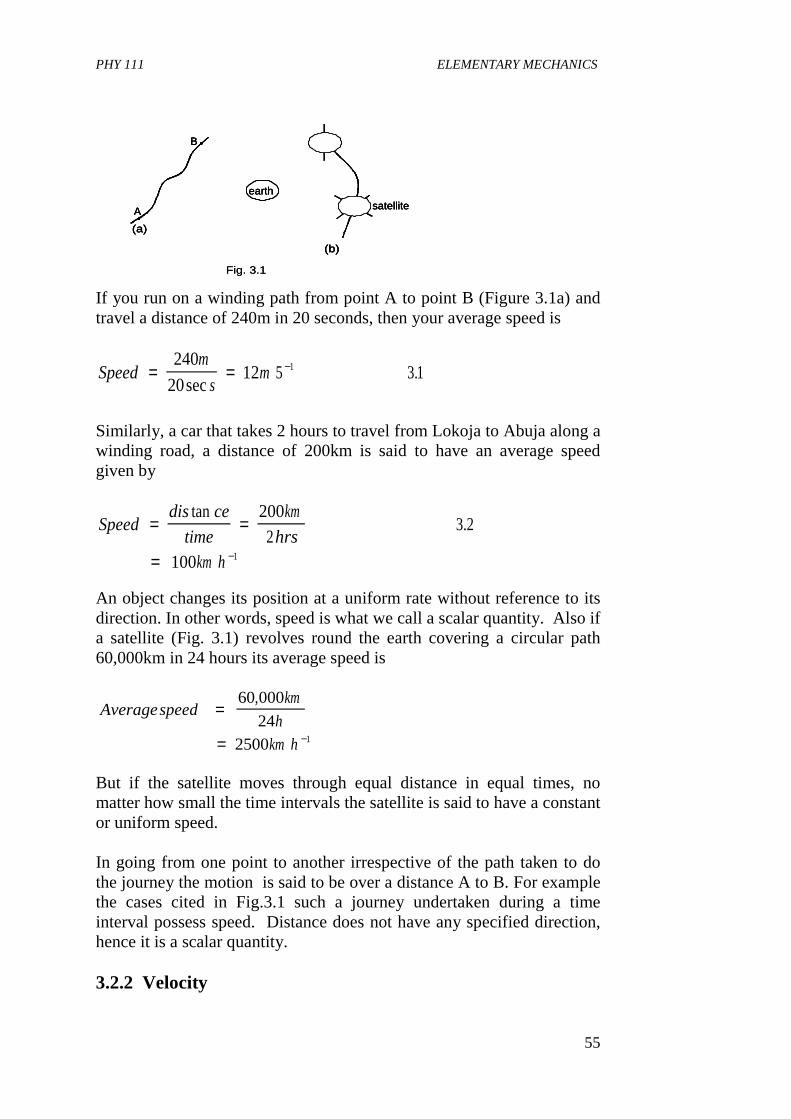
PHY 111 ELEMENTARY MECHANICS
55
A
B
(a)
earthsatellite
(b)
Fig. 3.1
A
B
(a)
earthsatellite
(b)
A
B
(a)
earthsatellite
(b)
Fig. 3.1
If you run on a winding path from point A to point B (Figure 3.1a) and travel a distance of 240m in 20 seconds, then your average speed is
Similarly, a car that takes 2 hours to travel from Lokoja to Abuja along a winding road, a distance of 200km is said to have an average speed given by
An object changes its position at a uniform rate without reference to its direction. In other words, speed is what we call a scalar quantity. Also if a satellite (Fig. 3.1) revolves round the earth covering a circular path 60,000km in 24 hours its average speed is
But if the satellite moves through equal distance in equal times, no matter how small the time intervals the satellite is said to have a constant or uniform speed. In going from one point to another irrespective of the path taken to do the journey the motion is said to be over a distance A to B. For example the cases cited in Fig.3.1 such a journey undertaken during a time interval possess speed. Distance does not have any specified direction, hence it is a scalar quantity. 3.2.2 Velocity
Speedm
sm= = −240
2012 5 3 11
sec.
Speeddis ce
time
km
hrs
km h
= =
= −
tan.
200
23 2
100 1
Averagespeedkm
h
km h
=
= −
60 000
242500 1
,
PHY 111 ELEMENTARY MECHANICS
56
A particle or car travelling between two locations and limited to make the journey in a specified direction, say 300 due North in some time interval is said to posses velocity, because
Consider a particle moving along the x-axis as in Figure 3.2a above. The curve in Figure 3.2b shows the graph of its displacement with time. At time t, the particle is at point P in Figure 3.2a where its coordinate is x1. At a later time t2 whose coordinate is x�it has moved to point 2.
The corresponding points on Figure 3.2b are labelled p and q. The displacement of this particle is then given by the x with magnitude x�vector 2 - x1 along a specified direction the x-axis
which is a straight line. The average velocity , of the particle is defined by
where ∆x = x2 - x1, is the displacement and ∆t is the time interval between when the particle is at point P and when it is at point Q. Note that average velocity here is a vector quantity because is a
vector quantity since is a scalar quantity. The direction of is the same as
the direction of the displacement vector. The magnitude of the average velocity is
In figure 3.2b, the average velocity is represented by the slope of the chord pq given by the ratio of
This is exactly the same as we got from figure 2a. Rewriting equation 3.5a we get that
velocitydisplacement
Time= 3 3.
∨
∨ =→ ∆
∆x
t3 4.
∆∆
x
t
∆ t ∨→∨→
∨ = ∨ =−−
=x x
t t
x
ta2 1
2 1
3 5∆∆
.
x x or x to t t or t
i e
Slopex x
t t
x
tb
2 1 2 1
2 1
2 1
3 5
− −
=−−
= = ∨
,
. .
.
∆ ∆
∆∆
PHY 111 ELEMENTARY MECHANICS
57
x t= ∨→
3 8.
If we take the time the particle starts its journey to be time t = 0, then the corresponding position is taken as x0 (i.e. initial position). After a later time t, the particle is taken to be at position x then equation 3.6 becomes
Now, if the particle is at the origin when t = 0, then x0 = 0 and equation 3.7 reduces to
Instantaneous velocity
The velocity of a particle at some one instant of time, or at some one point of its path, is called its instantaneous velocity. We have seen
that average velocity is associated with the entire displacement and the
entire time interval. When the point Q, taken to be closer and closer to
point p, the average velocity could be computed for very small time intervals- until a limiting time interval is reached. This limiting time interval we refer to as an instant of time. Hence we define instantaneous velocity as
Instantaneous velocity is also a vector quantity whose direction is the limiting direction of the displacement vector. By convention, a
positive velocity indicates that it is towards the right along the x-axis of the coordinate system. Note that as point Q approaches point p in Figure 3.2a, point q approaches point p in Figure 3.2b, in the limiting case the slope of the chord pq equals the slope of the tangent to the curve at point p. (Take note that the diagrams have not been drawn to scale).
The instantaneous velocity at any point of a coordinate-time graph therefore equals the slope of the tangent to the graph at that point.
As a rule of thumb, if the tangent slopes upwards to the right , its slope is positive, the velocity is positive, and the motion is to the right. But if
x x t t2 1 2 1 3 6− = ∨ −( ) .
x x t− = ∨→
0 3 7.
∆x∆t
∨ =→
lim.
∆∆∆t
x
t03 9
∆x
PHY 111 ELEMENTARY MECHANICS
58
the tangent slopes downwards to the right, the velocity is negative. At a point where the tangent is horizontal, its slope is zero and its velocity is zero. If distance is given in meters and time in seconds, velocity is expressed in meters per second (m s-1). Other common units of velocity are:
Feet per second (ft s-1) centimeters per second(cm s-1) miles per hour (mi h-1) and knot (1 knot = 1 nautical mile per hour).
Self Assessment Exercise 3.1 Suppose the motion of the particle in Figure 3.2 is described as the equation x = a + bt2, where a = 20cm and b = 4cm s2, (a) Find the displacement of the particle in the time interval between
t, = 2s and t2 = 5s (b) Find the average velocity in this time interval (c) Find the instantaneous velocity at time t1 = 2s. Solution For (a) at time t1 = 2s the position is x1 = 20cm + (4cm s2) (2s) = 36cm at time t2 = 5s; x2 = 20cm + (4cm s2)(5s) = 120cm The displacement is therefore x2 - x1, = (120 - 36)cm = 84cm For (b): The average velocity in this time interval is
x = 20cm + (4cm s2) (2s + )2 = 36 cm + (16cm s-1) + (4cm s-2) ()2
The displacement during the interval is = 36cm + (16cm s-1) (4cm s-2) - 36cm = (16cm s-1) + (4cm s2)
The average velocity during is
∨ =−−
=→
−x x
t t
cm
scm s2 1
2 1
184
328
∆t∆t∆t
∆t∆x ∆t∆t 2
∆t∆t 2
∆t
PHY 111 ELEMENTARY MECHANICS
59
For the instantaneous velocity at t = 2s, we let approach zero in the expression for
This corresponds to the slope of the tangent at point P in Figure 3.2b. 3.2.3 Acceleration: Average and instantaneous acceleration When a body accelerates in motion, it means that its velocity changes continuously as the motion proceeds. Figure 3.3 shows a particle, P moving along the x-axis. The vector v1 is its instantaneous velocity at point P and the vector v2 represents its instantaneous velocity at point Q. Its instantaneous velocities between points P and Q are plotted against time in Figure 3.3b as shown above. Points p and q corresponds to points P and Q in part (a). Thus, the average acceleration of the particle is given as the ratio of change in velocity to the elapsed time i.e
where t1, and t2 are the times corresponding to the velocities.
Note that since are vectors, the quantity is a vector
difference and must be found by the method of vector subtraction you learnt in units 3 and 4. But in rectilinear motion both vectors lie in the
∨ = = +− −∆∆
∆x
tcm s cm s t16 41 1( )
∨
∴∨ = −16 1cm s
av v
t t
v
t
→=
−−
=2 1
2 1
310∆∆
.
v and v1 2
→ →
v and v1 2
→ →
v v2 1
→ →−
∆t
PHY 111 ELEMENTARY MECHANICS
60
same straight line. So in this case, the magnitude of the vector difference equals the difference in the magnitudes of the vectors. In Figure 3.3b the magnitude of the average acceleration is represented by the slope of the chord pq.
The instantaneous acceleration, of a body i.e. its acceleration at some one instant of time or at some one point of its path is defined
in the same way as for instantaneous velocity. Hence it is defined as the limiting value of the average acceleration when the second position of the particle is taken much closer to the first position as tends to zero.
i.e.
Note that the direction of the instantaneous acceleration is the limiting direction of the vector change in velocity. Instantaneous acceleration plays an important role in physics and is more frequently used than average acceleration. Subsequently, the term acceleration will be used to mean instantaneous acceleration. Acceleration, of course, is a vector quality and the definition just given above applies to whether the path of motion of the particle is straight or curved. In Figure 3.3b the instantaneous acceleration is equal to the slope of the tangent to the curve at any point say, p of a velocity-time graph. If velocity is expressed in metres per second, then acceleration is expressed in metres per square second (m s-2). Other common units of acceleration are feet per square pound (ft s-2) and centimeters per square second (cm s-1). Note that when a body is slowing down its motion, we say it is decelerating. Self Assessment Exercise 3.2 Given that the velocity of a particle is V = m + nt2 where m = 10cm s-1 and n = 2cm s-1 (a) find the change in velocity of the particle in the time internal
between t2 = 2s and t2 = 5s (b) find the average acceleration in this time interval. (c) find the instantaneous acceleration at time t1 = 2s Solution: Given v = m + nt2 for (a) : At time t1 = 2s (m = 10cm 5-1, n = 2cm v1 = 10cm s-1 + (2cm s-3)(2s)2 = 18cm s-1-
∆t
a t ov
t
→= →
∆
∆∆
lim
.311
PHY 111 ELEMENTARY MECHANICS
61
t
vo
O
at
vvo
v
Fig. 3.4
t
v
t
vo
O
at
vvo
v
Fig. 3.4
t
v
At time t2 = 5s V2 = 10cm s-1 + (2cm s-3)(5s)2 = 60cm s-1 The average velocity is therefore v2 - v1 = (60 - 18)cm s-1 = 42cm s-1
for (b)
This corresponds to the slope of the chord pq in Figure 3.3b For (c) at time t = 2s + ∆t v = 10cm s-1 + (2cm s-3)(2s + ∆t)2 = 18cm s-1 + (8cm s-2) ∆t (2cm s-3)∆t2 t is�The change in velocity during -18cm s-1 = (8cm s-2t�) + (2cm s-3t)�)(2 t is�Hence, the average acceleration during v = 18cm s�-1 + (8cm s-2t +�) (2cm s-3t)�)(2
at time t = 2 as is
This corresponds to the slope of the tangent at the point p in Figure 3.3b
at t
cm s
scm s
→ −−=
∨ − ∨−
= =2 1
2 1
1242
314
a→ →
= ∨ =∆ ∆ ∆ 8cm s t + (2cm s ) ( t)-2 -3 2
a→∆t → 0a→
a→
= 8cm s . -2
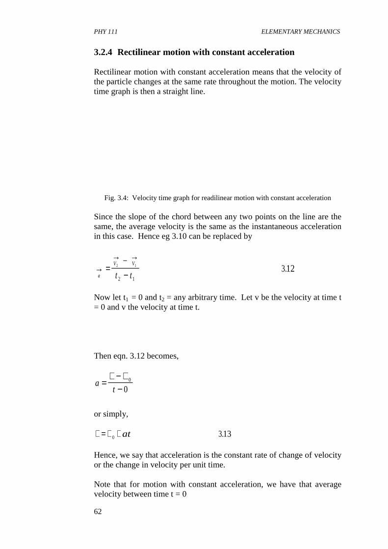
PHY 111 ELEMENTARY MECHANICS
62
3.2.4 Rectilinear motion with constant acceleration Rectilinear motion with constant acceleration means that the velocity of the particle changes at the same rate throughout the motion. The velocity time graph is then a straight line.
Fig. 3.4: Velocity time graph for readilinear motion with constant acceleration Since the slope of the chord between any two points on the line are the same, the average velocity is the same as the instantaneous acceleration in this case. Hence eg 3.10 can be replaced by
Now let t1 = 0 and t2 = any arbitrary time. Let v be the velocity at time t = 0 and v the velocity at time t. Then eqn. 3.12 becomes,
or simply,
Hence, we say that acceleration is the constant rate of change of velocity or the change in velocity per unit time. Note that for motion with constant acceleration, we have that average velocity between time t = 0
→ =→ →
−a
V V
t t2 1
2 1
312_
.
at
=∨ − ∨
−0
0
∨ = ∨ +0 313at .
PHY 111 ELEMENTARY MECHANICS
63
and time, t is
When the acceleration is not constant the velocity time graph is curved as in Figure 3.3. Recall that by definition
for time t = 0 and a later time t Let x0 be the position at t = 0 (initial position) and let x be the position at time t (final position). Then, the proceeding equation becomes
3 substituting the expression for v in equation 3.14 gives
Then using equation 3.13 and 3.16 to eliminate v and t and substituting for v in equation 3.13. We get
Now solving eqn. 3.13 for t and putting the result in eqn. 3.16 we have
Note that the following equations 3.13, 3.16, 3.17 and 3.18 are called the equations of motion with constant acceleration. You are required to know these equations of motion by root so that you can easily apply them in solving problems in physics. Self Assessment Exercise
∨=∨ +∨0
2314.
∨ =−−
→ x x
t t2 1
2 1
x x t− = ∨→
0 315.
x x t− =∨ + ∨
00
2316( ) .
x xat
or
x x t at
− =∨ + ∨ +
− = ∨ +
00 0
0 01
22
2
317
( )
.
x xa a
or
a x x
− =∨ + ∨ ∨ − ∨
=∨ − ∨
∨ = ∨ + −
00 0
2 20
2 20 0
2 2
2 318
( ) ( ) ( )
( ) .
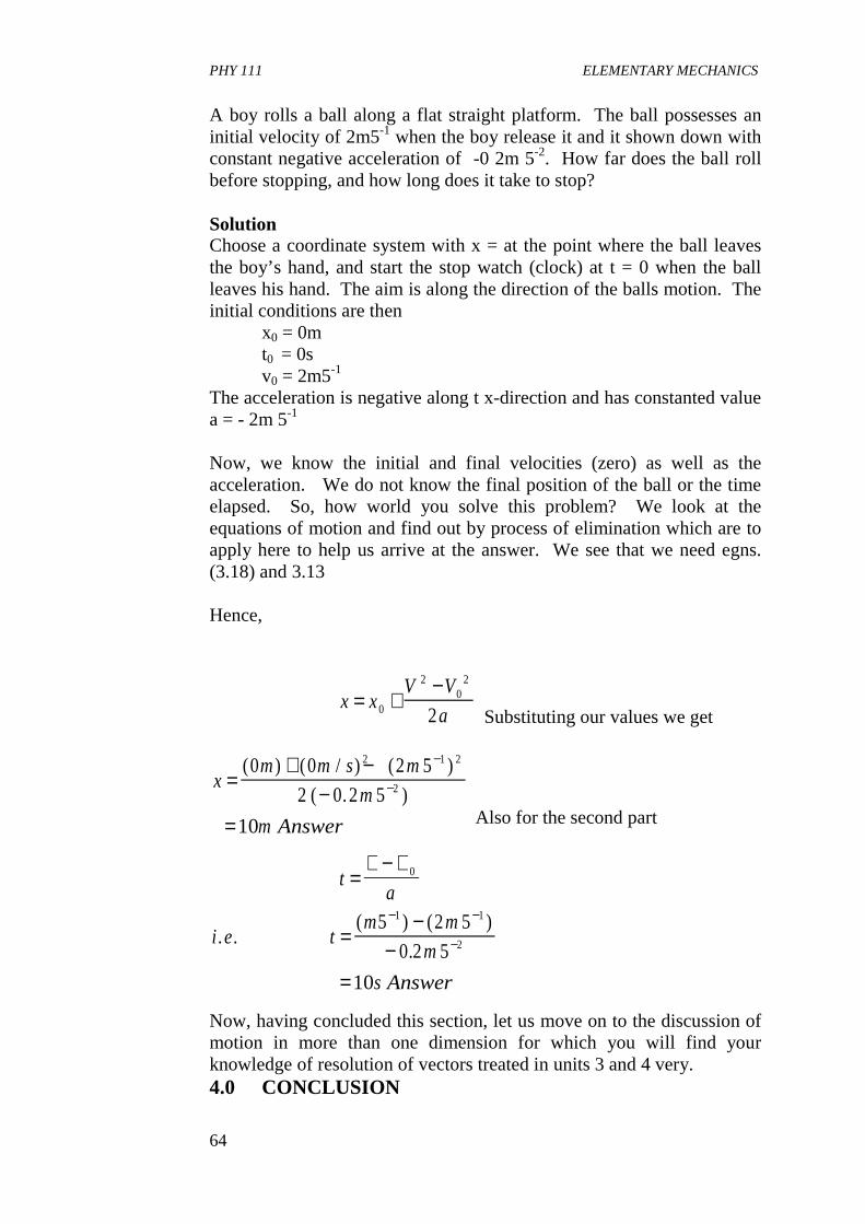
PHY 111 ELEMENTARY MECHANICS
64
A boy rolls a ball along a flat straight platform. The ball possesses an initial velocity of 2m5-1 when the boy release it and it shown down with constant negative acceleration of -0 2m 5-2. How far does the ball roll before stopping, and how long does it take to stop? Solution Choose a coordinate system with x = at the point where the ball leaves the boy’s hand, and start the stop watch (clock) at t = 0 when the ball leaves his hand. The aim is along the direction of the balls motion. The initial conditions are then x0 = 0m t0 = 0s v0 = 2m5-1 The acceleration is negative along t x-direction and has constanted value a = - 2m 5-1
Now, we know the initial and final velocities (zero) as well as the acceleration. We do not know the final position of the ball or the time elapsed. So, how world you solve this problem? We look at the equations of motion and find out by process of elimination which are to apply here to help us arrive at the answer. We see that we need egns. (3.18) and 3.13 Hence,
Substituting our values we get
Also for the second part
Now, having concluded this section, let us move on to the discussion of motion in more than one dimension for which you will find your knowledge of resolution of vectors treated in units 3 and 4 very. 4.0 CONCLUSION
x xV V
a= +
−0
20
2
2
xm m s m
m
m Answer
=+ −
−=
−
−
( ) ( / ) ( )
( . )
0 0 2 5
2 0 2 5
10
2 1 2
2
ta
i e tm m
m
s Answer
=∨ − ∨
=−
−=
− −
−
0
1 1
2
5 2 5
0 2 5
10
. .( ) ( )
.
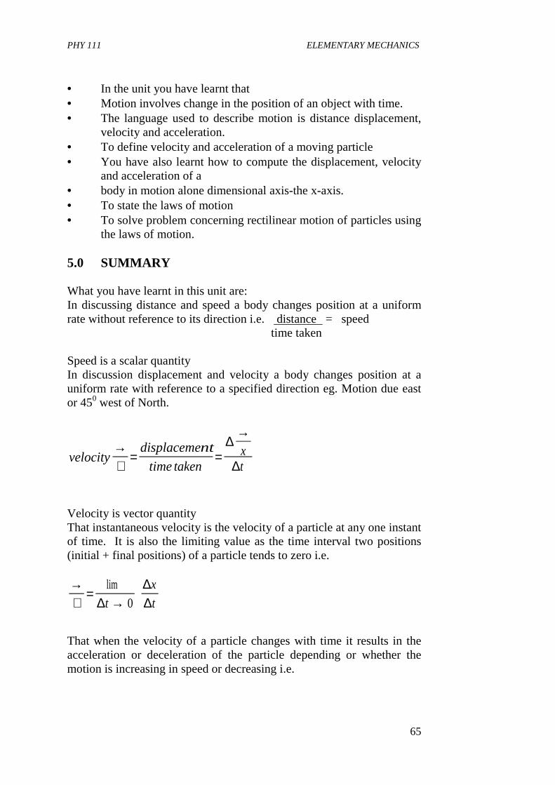
PHY 111 ELEMENTARY MECHANICS
65
• In the unit you have learnt that • Motion involves change in the position of an object with time. • The language used to describe motion is distance displacement,
velocity and acceleration. • To define velocity and acceleration of a moving particle • You have also learnt how to compute the displacement, velocity
and acceleration of a • body in motion alone dimensional axis-the x-axis. • To state the laws of motion • To solve problem concerning rectilinear motion of particles using
the laws of motion. 5.0 SUMMARY What you have learnt in this unit are: In discussing distance and speed a body changes position at a uniform rate without reference to its direction i.e. distance = speed time taken Speed is a scalar quantity In discussion displacement and velocity a body changes position at a uniform rate with reference to a specified direction eg. Motion due east or 450 west of North.
Velocity is vector quantity That instantaneous velocity is the velocity of a particle at any one instant of time. It is also the limiting value as the time interval two positions (initial + final positions) of a particle tends to zero i.e.
That when the velocity of a particle changes with time it results in the acceleration or deceleration of the particle depending or whether the motion is increasing in speed or decreasing i.e.
velocitydisplacement
timetakenxt
→∨
= =
→∆
∆
→∨
=→
lim
∆∆∆t
x
t0
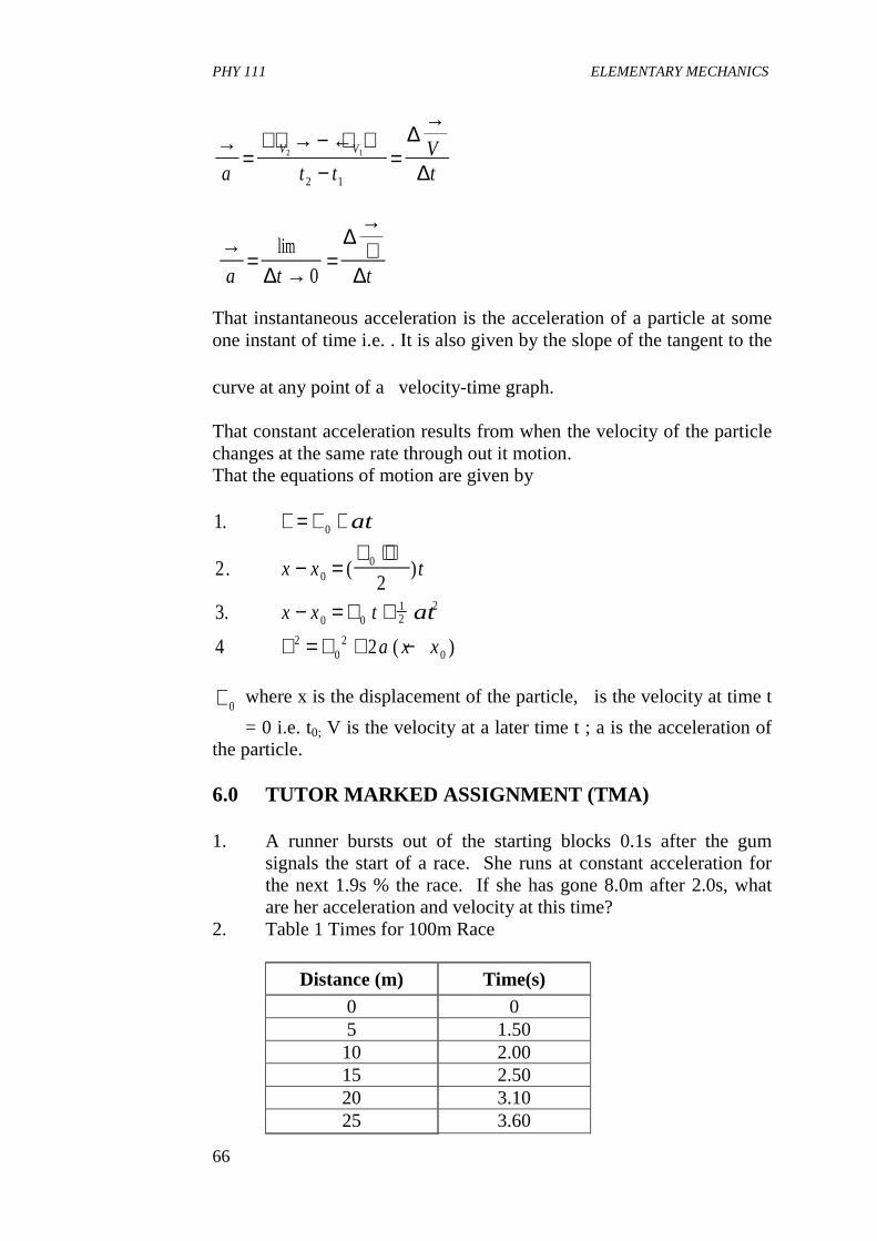
PHY 111 ELEMENTARY MECHANICS
66
That instantaneous acceleration is the acceleration of a particle at some one instant of time i.e. . It is also given by the slope of the tangent to the
curve at any point of a velocity-time graph. That constant acceleration results from when the velocity of the particle changes at the same rate through out it motion. That the equations of motion are given by
where x is the displacement of the particle, is the velocity at time t
= 0 i.e. t0; V is the velocity at a later time t ; a is the acceleration of the particle. 6.0 TUTOR MARKED ASSIGNMENT (TMA) 1. A runner bursts out of the starting blocks 0.1s after the gum
signals the start of a race. She runs at constant acceleration for the next 1.9s % the race. If she has gone 8.0m after 2.0s, what are her acceleration and velocity at this time?
2. Table 1 Times for 100m Race
Distance (m) Time(s) 0 0 5 1.50 10 2.00 15 2.50 20 3.10 25 3.60
→=
→ − ← −
=
→
a t tVt
V V2 1
2 1
∆
∆
→=
→=
→∨
a t t
lim
∆
∆
∆0
1
22
3
4 2
0
00
0 012
2
20
20
.
. ( )
.
( )
∨ = ∨ +
− =∨ + ∨
− = ∨ +
∨ = ∨ + −
at
x x t
x x t at
a x x
∨0
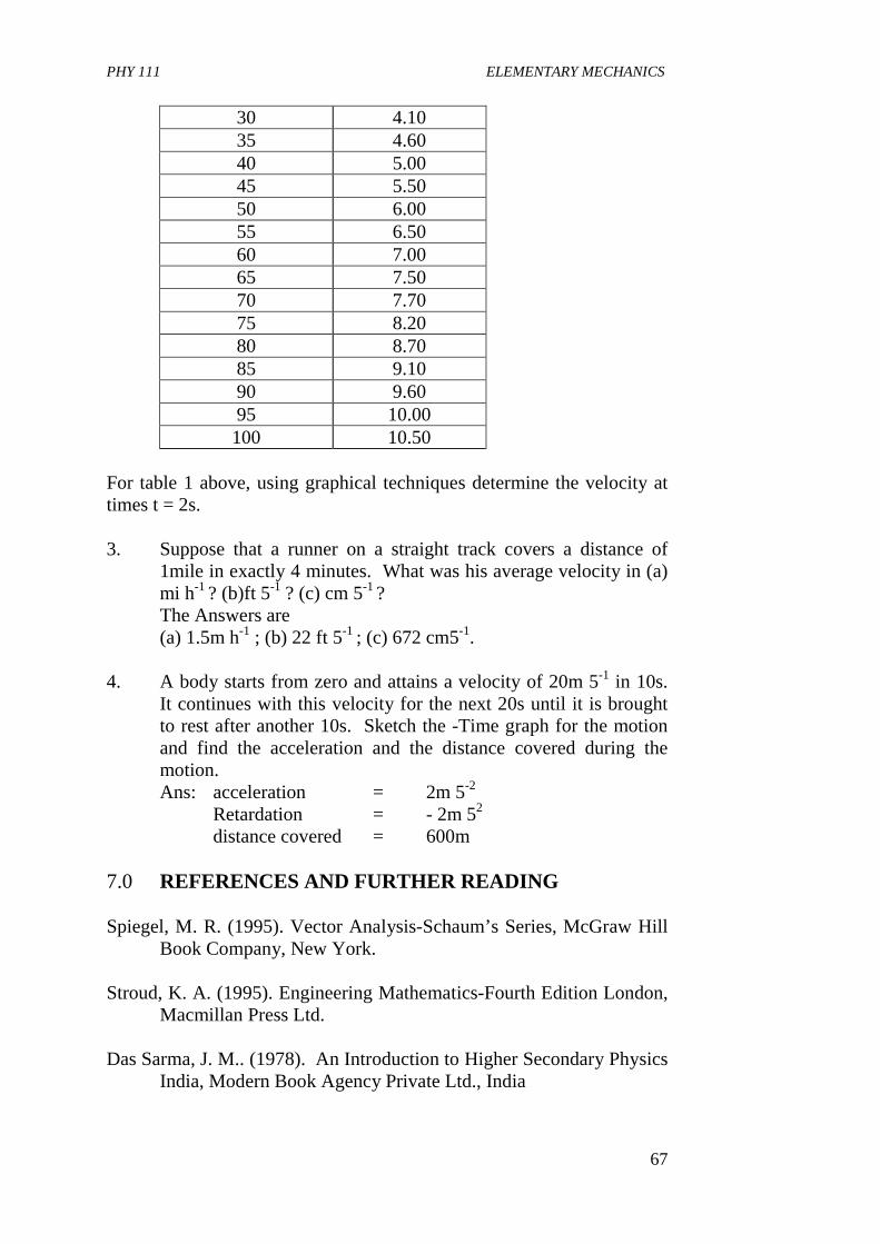
PHY 111 ELEMENTARY MECHANICS
67
30 4.10 35 4.60 40 5.00 45 5.50 50 6.00 55 6.50 60 7.00 65 7.50 70 7.70 75 8.20 80 8.70 85 9.10 90 9.60 95 10.00 100 10.50
For table 1 above, using graphical techniques determine the velocity at times t = 2s. 3. Suppose that a runner on a straight track covers a distance of
1mile in exactly 4 minutes. What was his average velocity in (a) mi h-1 ? (b)ft 5-1 ? (c) cm 5-1 ?
The Answers are (a) 1.5m h-1 ; (b) 22 ft 5-1 ; (c) 672 cm5-1. 4. A body starts from zero and attains a velocity of 20m 5-1 in 10s.
It continues with this velocity for the next 20s until it is brought to rest after another 10s. Sketch the -Time graph for the motion and find the acceleration and the distance covered during the motion.
Ans: acceleration = 2m 5-2 Retardation = - 2m 52 distance covered = 600m
7.0 REFERENCES AND FURTHER READING Spiegel, M. R. (1995). Vector Analysis-Schaum’s Series, McGraw Hill
Book Company, New York. Stroud, K. A. (1995). Engineering Mathematics-Fourth Edition London,
Macmillan Press Ltd. Das Sarma, J. M.. (1978). An Introduction to Higher Secondary Physics
India, Modern Book Agency Private Ltd., India
PHY 111 ELEMENTARY MECHANICS
68
Fishbane, P. M., Gasiorowicz, S and Thronton S. T. (1996). Physics for Scientist and Engineer 2rd Ed. Vol. 1 New Jersey, in Prentice Hall, New Jersey
Indira Gandi National Open University School of Sciences. PHE 01,
Elementary Mechanics.
PHY 111 ELEMENTARY MECHANICS
69
Module 2 Unit 1: Motion in More Than One Dimension Unit 2: Force Unit 3: The Projectile Motion Unit 4: Impulse and Linear Momentum Unit 5: Linear Collision UNIT 1 MOTION IN MORE THAN ONE DIMENSION CONTENTS 1.0 Introduction 2.0 Objectives 3.0 Main Body
3.1 Velocity and Acceleration 3.2 Uniform Circular Motion 3.3 Relative Motion
4.0 Conclusion 5.0 Summary 6.0 Tutor Marked Assignment (TMAs) 7.0 References and Further Reading 1.0 INTRODUCTION In treating the topic, motion, we have so far discussed only motion along a straight line or rectilinear motion. In this chapter, we shall consider motion in more than one dimension. This is the same thing as discussing motion in a plane and in three dimensions. You have realised, from your studies of unit 1 to 4 that our physical world is in three dimensional space. So, as a particle moves, its co-ordinates with reference to a specified frame changes in two or three dimensions depending on where the motion is taking place. Having realised from unit 5 that the parameters for describing motion which include displacement/distance, velocity and acceleration are vector quantities, we shall draw on our knowledge of vectors from units 3 and 4 to understand this Unit better. We shall also study circular motion which will give us an insight into satellite motion, and then conclude the Unit with studies of Relative Motion. Other types of motion and causes of motion will be developed in the subsequent Units.
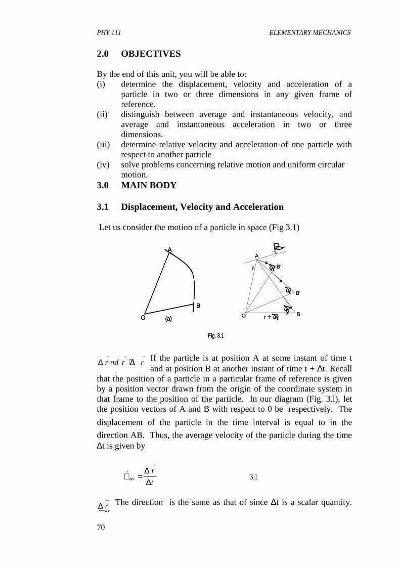
PHY 111 ELEMENTARY MECHANICS
70
Fig. 3.1
A
O (a)
B
B"
B'
B
A
O
�r
�r
�r
r + �r
r
v�
Fig. 3.1
A
O (a)
B
A
O (a)
B
B"
B'
B
A
O
�r
�r
�r
r + �r
r
v�
2.0 OBJECTIVES By the end of this unit, you will be able to: (i) determine the displacement, velocity and acceleration of a
particle in two or three dimensions in any given frame of reference.
(ii) distinguish between average and instantaneous velocity, and average and instantaneous acceleration in two or three dimensions.
(iii) determine relative velocity and acceleration of one particle with respect to another particle
(iv) solve problems concerning relative motion and uniform circular motion.
3.0 MAIN BODY 3.1 Displacement, Velocity and Acceleration Let us consider the motion of a particle in space (Fig 3.1)
If the particle is at position A at some instant of time t and at position B at another instant of time t + ∆t. Recall
that the position of a particle in a particular frame of reference is given by a position vector drawn from the origin of the coordinate system in that frame to the position of the particle. In our diagram (Fig. 3.l), let the position vectors of A and B with respect to 0 be respectively. The
displacement of the particle in the time interval is equal to in the
direction AB. Thus, the average velocity of the particle during the time ∆t is given by
The direction is the same as that of since ∆t is a scalar quantity.
r and r r→ → →
+ ∆∆t∆ r→
∨ =→
→
av
r
t
∆∆
3 1.
∨→
av∆ r
→
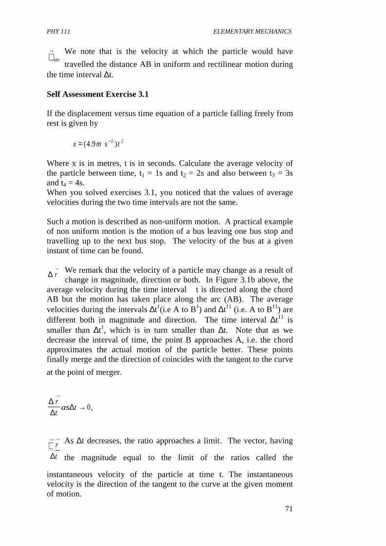
PHY 111 ELEMENTARY MECHANICS
71
We note that is the velocity at which the particle would have
travelled the distance AB in uniform and rectilinear motion during the time interval ∆t. Self Assessment Exercise 3.1 If the displacement versus time equation of a particle falling freely from rest is given by
Where x is in metres, t is in seconds. Calculate the average velocity of the particle between time, t1 = 1s and t2 = 2s and also between t3 = 3s and t4 = 4s. When you solved exercises 3.1, you noticed that the values of average velocities during the two time intervals are not the same. Such a motion is described as non-uniform motion. A practical example of non uniform motion is the motion of a bus leaving one bus stop and travelling up to the next bus stop. The velocity of the bus at a given instant of time can be found.
We remark that the velocity of a particle may change as a result of change in magnitude, direction or both. In Figure 3.1b above, the
average velocity during the time interval �t is directed along the chord AB but the motion has taken place along the arc (AB). The average velocities during the intervals ∆t1(i.e A to B1) and ∆t11 (i.e. A to B11) are different both in magnitude and direction. The time interval ∆t11 is smaller than ∆t1, which is in turn smaller than ∆t. Note that as we decrease the interval of time, the point B approaches A, i.e. the chord approximates the actual motion of the particle better. These points finally merge and the direction of coincides with the tangent to the curve
at the point of merger.
As ∆t decreases, the ratio approaches a limit. The vector, having
the magnitude equal to the limit of the ratios called the
instantaneous velocity of the particle at time t. The instantaneous velocity is the direction of the tangent to the curve at the given moment of motion.
∨→
av
x m s t= −( . )4 9 2 2
∆ r→
∆∆
r
t
→
∨→
∆∆
∆r
tas t
→
→ 0,
PHY 111 ELEMENTARY MECHANICS
72
Thus,
In other words, the instantaneous velocity is the derivative of with
respect to time. 3.2a
It follows from equation 3.2a that if has components x, y, z then
differentiating the RHS we get
since i, j, k are independent of time
Note that if we were using coordinates alone to write the equations for velocity, we would have to write three equations as in Equation 3.2b. The advantage of the use of vectors is that it enables us to write a single equation as in equation 3.2a. Representing the instantaneous velocities of the particle when it passes through points A and B of its path as shown in Figure 3.2,
∨ = → =→
→ →
∆∆∆
tr
t
d r
dt0 3 1
lim.
.
r→
∨ =→
→d r
dt
r→
∨ = = + +→
→d r
dt
d
dtxi yj zk( )
∨ = + + + + +
= + +
→xdi
dtidx
dtydj
dtjdy
dtz
dk
dtk
dz
dt
dx
dti
dy
dtj
dz
dtk
= ∨ + ∨ + ∨
∨ = ∨ = ∨ =→ → →
x y z
x y z
i j k where
dx
dt
dy
dt
dz
dtb, , .3 2
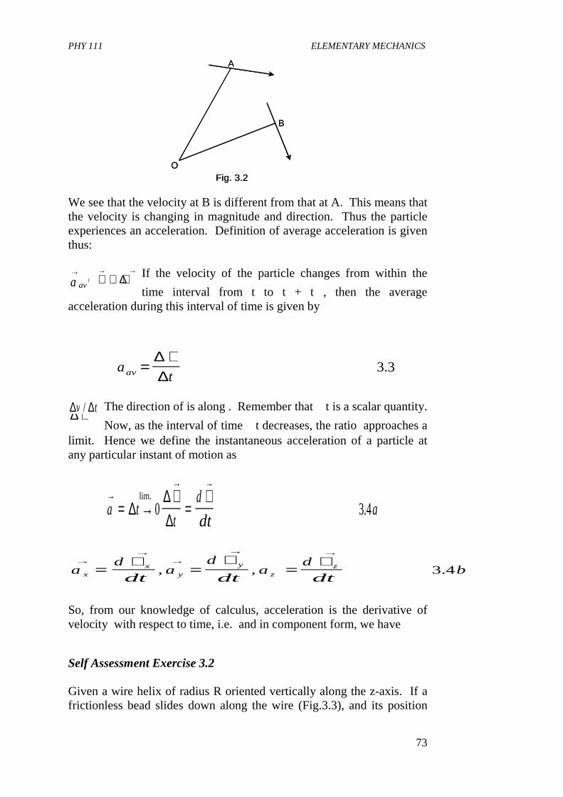
PHY 111 ELEMENTARY MECHANICS
73
B
A
Fig. 3.2O
B
A
Fig. 3.2O
We see that the velocity at B is different from that at A. This means that the velocity is changing in magnitude and direction. Thus the particle experiences an acceleration. Definition of average acceleration is given thus:
If the velocity of the particle changes from within the
time interval from t to t + t�, then the average acceleration during this interval of time is given by
The direction of is along . Remember that �t is a scalar quantity.
Now, as the interval of time �t decreases, the ratio approaches a limit. Hence we define the instantaneous acceleration of a particle at any particular instant of motion as
So, from our knowledge of calculus, acceleration is the derivative of velocity with respect to time, i.e. and in component form, we have
Self Assessment Exercise 3.2 Given a wire helix of radius R oriented vertically along the z-axis. If a frictionless bead slides down along the wire (Fig.3.3), and its position
∨ ∨ + ∨→ → →
to ∆a av
→
atav =∨∆
∆3 3.
a av
→∆ ∨
→∆ ∆v t/
a tt
d
dta
→→ →
= →∨
=∨
∆∆∆
0 3 4lim.
.
∨→
ad
dt
d r
dt
→→ →
=∨
−2
2 ,ad
dta
d
dta
d
dtbx
xy
y
zz
→→
→→ →
=∨
=∨
=∨
, , .3 4
PHY 111 ELEMENTARY MECHANICS
74
vector varies with time as
where b and c are constants, find and , where and are the
velocity and acceleration expressed as functions of t. Solution:
From the expression for given. We know that for the three axes,
x, y, z. x = R cos bt2, y = R sin bt2 , z = ½ ct2
Recall that
The acceleration is given by
Self Assessment Exercise 3.3 A particle moves along the curve y = Ax2 such that x = Bt, A and B are constants.
(a) Express the position vector of the particle in
R
Fig. 3.3
R
Fig. 3.3
r t R bt i R bt j ct k→
= + −( ) ( cos ) ( sin )2 2 12
2
∨→
( )ta t→
( )∨→
( )ta t→
( )
r t→
( )
∨ = = + +
∴ ∨ = − + −
→→
→
( )
( ) ( sin ) ( cos ) ( )
td r
dt
d x
dti
d y
dtj
d z
dtk
t tb R bt i t bR bt j ct k2 22 2
a t→
( )
a td
dtt b R bt Rb bt i
t RbSinbt Rb bt j ck
→→
=∨
= −
+ − + −
( ) ( cos sin )
( cos )
4 2
4 2
2 2 2 2
2 2 2 2
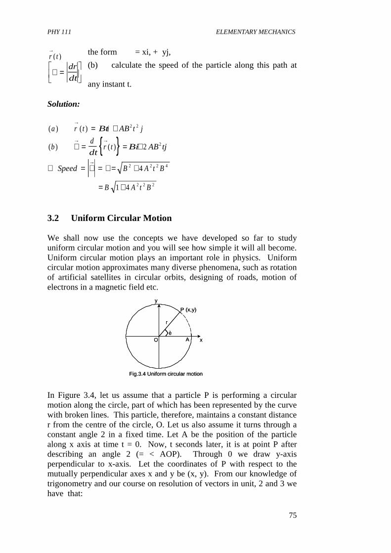
PHY 111 ELEMENTARY MECHANICS
75
x
r
èO
y
A
P (x,y)
Fig.3.4 Uniform circular motion
x
r
èO
y
A
P (x,y)
Fig.3.4 Uniform circular motion
the form = xi, + yj,
(b) calculate the speed of the particle along this path at
any instant t. Solution:
3.2 Uniform Circular Motion We shall now use the concepts we have developed so far to study uniform circular motion and you will see how simple it will all become. Uniform circular motion plays an important role in physics. Uniform circular motion approximates many diverse phenomena, such as rotation of artificial satellites in circular orbits, designing of roads, motion of electrons in a magnetic field etc. In Figure 3.4, let us assume that a particle P is performing a circular motion along the circle, part of which has been represented by the curve with broken lines. This particle, therefore, maintains a constant distance r from the centre of the circle, O. Let us also assume it turns through a constant angle 2 in a fixed time. Let A be the position of the particle along x axis at time t = 0. Now, t seconds later, it is at point P after describing an angle 2 (= < AOP). Through 0 we draw y-axis perpendicular to x-axis. Let the coordinates of P with respect to the mutually perpendicular axes x and y be (x, y). From our knowledge of trigonometry and our course on resolution of vectors in unit, 2 and 3 we have that:
r t→
( )
∨ =
dr
dt
{ }( ) ( )
( ) ( )
a r t Bti AB t j
bd
dtr t Bi AB tj
Speed B A t B
B A t B
→
→ →
→
= +
∨ = = +
∴ = ∨ = ∨ = +
= +
2 2
2
2 2 2 4
2 2 2
2
4
1 4
PHY 111 ELEMENTARY MECHANICS
76
x = r Cos 2 y = r Sin 2 3.5a Now, if the angle described per second by the particle be a constant equal to 2 (pronounced ‘omega’) radians, then 2 = �t and eqn. 3.5 can be written as x = r Cos 2t
y = r Sin 2t 3.5b
T is also known as the angular speed of the particle. We note that the position vector of the particle at P is given by = -r2 sin Tti + r 2cos 2tj 3.7
= Vx I + Vy j where Vx = - rT sin Tt, Vy = rT cos Tt 3.8 The magnitude of velocity is therefore,
What is the direction of this velocity? To find out, let us calculate
= (- rT Sin Tti + rT Cos Ttj).(Cos Tti + r Sin Ttj)
→= +
→= +
rxi yj
or
rr ti r wtj
3 6.
cos sin ,ω
→∨
=→d
dtr
→∨ = ∨ = ∨ + ∨
= =
x y
r w rw
2 2
2 2 3 9.
∨→ →
. r
∨→ →
. r
PHY 111 ELEMENTARY MECHANICS
77
= - r2T Sin Tt cos Tt + r2 Cos Tt Sin Tt = 0
we see that
Since V. r = 0 is always perpendicular to. This implies that V is
always along the tangent to the circular path. Eqn 3.9 reveals that
has a constant magnitude. We have found that for circular motion, the particles velocity constantly changes direction because it (the velocity) is always along the tangent at any point. So, we conclude that the velocity vector is not constant, i.e., the particle has an acceleration. Let us denote the particle acceleration by and then find the appropriate
expression for it . Recall that acceleration
We, therefore, have from Eqn (3.8) that Since v = Tr from Eqn 3.9, we get
The negative sign in the expression for the acceleration Eqn (3.11) indicates that the acceleration is opposite to i.e. towards the centre
of the circle. I would then like you to remember that a particle moving with uniform angular speed in a circle, experiences an acceleration directed towards the centre. This is known as centripetal acceleration. Example
∨ =→ →
. r 0
∨→r→∨→
a R
→
=→
dv
dt
→= −
= − +
∴ = −→ →
arw wti rw wtj
w wti r wtj
a r
R
r
2 2
2
2
3 10
311
cos sin .
(cos sin )
.ω
→ − =∨
=∨
aRr
r
r rω
2
2
2
312.
→r
PHY 111 ELEMENTARY MECHANICS
78
Let us calculate the period of revolution of a satellite moving around the earth in a circular equatorial orbit, (Fig. 3.5). Let the velocity of the satellite in the
orbit be, and the radius of the orbit be r. Like any free object near the
earth’s surface, the satellite has an acceleration towards the centre of the earth (= g, say), which is the centripetal acceleration. It is this acceleration that causes it to follow the circular path. Hence from Eqn (3.12), we have
If the angular speed of the satellite is T, we get from Eqn (3.9) that
Again the time period T is given by
Where R = the radius of the earth and h = the height of the satellite above the surface of the earth.
Rh
Fig.3.5
Rh
Fig.3.5
∨→
gr
or g r
12
2 1
=∨
∨ =
ω
ω
2 2 1
21
r g r
or
g
r
=
=
Tr
g
or
TR h
g
= =
=+
22
2
1
1
πω π
π
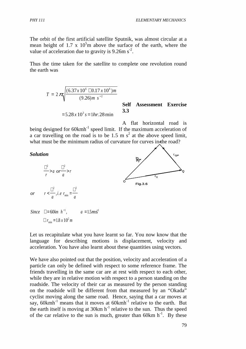
PHY 111 ELEMENTARY MECHANICS
79
Fig.3.6O
Q
P
r p
r Q
rQP
�
Fig.3.6O
Q
P
r p
r Q
rQP
�
The orbit of the first artificial satellite Sputnik, was almost circular at a mean height of 1.7 x 10⁵m above the surface of the earth, where the value of acceleration due to gravity is 9.26m s-2. Thus the time taken for the satellite to complete one revolution round the earth was
Self Assessment Exercise 3.3 A flat horizontal road is
being designed for 60kmh-1 speed limit. If the maximum acceleration of a car travelling on the road is to be 1.5 m s2 at the above speed limit, what must be the minimum radius of curvature for curves in the road? Solution
Let us recapitulate what you have learnt so far. You now know that the language for describing motions is displacement, velocity and acceleration. You have also learnt about these quantities using vectors. We have also pointed out that the position, velocity and acceleration of a particle can only be defined with respect to some reference frame. The friends travelling in the same car are at rest with respect to each other, while they are in relative motion with respect to a person standing on the roadside. The velocity of their car as measured by the person standing on the roadside will be different from that measured by an “Okada” cyclist moving along the same road. Hence, saying that a car moves at say, 60kmh-1 means that it moves at 60kmh-1 relative to the earth. But the earth itself is moving at 30km h-1 relative to the sun. Thus the speed of the car relative to the sun is much, greater than 60km h-1. By these
Tx x m
m s
x s hr
=+
= =
−26 37 10 0 17 10
9 26
5 28 10 1 28
6 6
2
3
π( . . )
( . )
. . min
∨>
∨>
<∨
=∨
∨ = =
∴ =
− −
2 2
2 2
1 1
2
60 1 5
1 8 10
ra or
ar
or ra
i e ra
Since km h a ms
r x m
, .
, .
.
min
min
PHY 111 ELEMENTARY MECHANICS
80
examples we are only trying to show that all motion is relative. This is interesting, isn’t it? Often in practical situation, we need to determine the relative position, velocity and acceleration of a particle or an object with respect to another one. In the next section we shall find out how this is done. 3.5 Relative Motion In this section, we shall discuss relative motion. Your knowledge of units 1, 3 and 4 will be applied here.
Let be the position vectors of particles P and Q, respectively,
at any instant of time, with respect to a fixed origin 0. This has been drawn in Figure 3.6 above.
Thus, the relative velocity. of P with respect to Q is got by
differentiating with respect to time.
Thus,
Relative acceleration of P with respect to Q us given by,
r and rp Q
→ →
r r r
or r r r
Q Qp p
Qp p Q
→ → →
→ → →
+ =
= − 316.
∨QprQp
→
∨ = = =
= ∨ −
→→ →
→ →
Qp Qp
p Q
Qp P Q
d
dtr
d r
dt
d r
dtor
v v 317.
aQp
→
ad
dt
d
dt
d
dtor
a a a
Qp QPp
QP P Q
Q→ →
→ →
→ → →
= ∨ =∨
−∨
= −
( )
.318
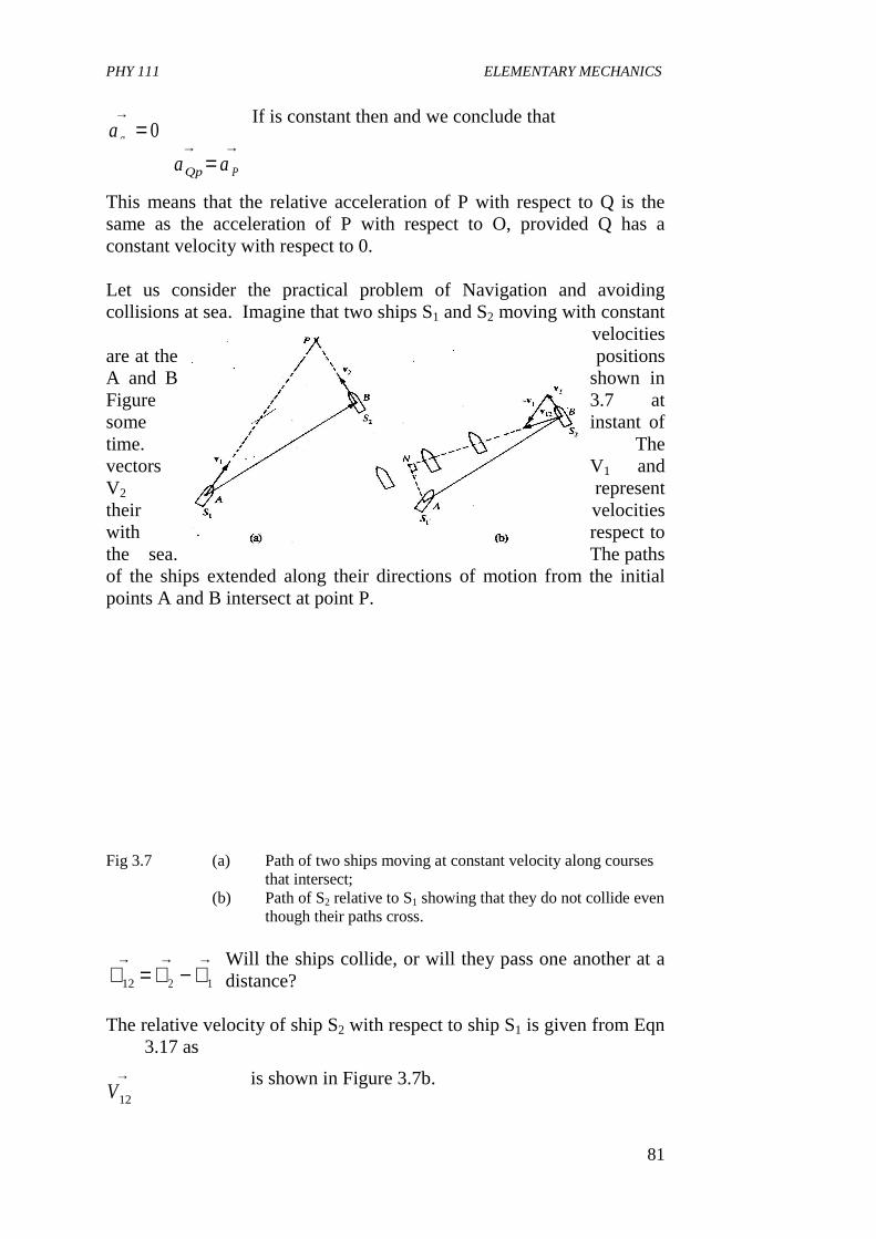
PHY 111 ELEMENTARY MECHANICS
81
If is constant then and we conclude that
This means that the relative acceleration of P with respect to Q is the same as the acceleration of P with respect to O, provided Q has a constant velocity with respect to 0. Let us consider the practical problem of Navigation and avoiding collisions at sea. Imagine that two ships S1 and S2 moving with constant
velocities are at the positions A and B shown in Figure 3.7 at some instant of time. The vectors V1 and V2 represent their velocities with respect to the sea. The paths of the ships extended along their directions of motion from the initial points A and B intersect at point P. Fig 3.7 (a) Path of two ships moving at constant velocity along courses
that intersect; (b) Path of S2 relative to S1 showing that they do not collide even
though their paths cross. Will the ships collide, or will they pass one another at a distance?
The relative velocity of ship S2 with respect to ship S1 is given from Eqn 3.17 as
is shown in Figure 3.7b.
∨→
Qaa
→= 0
a aQp P
→ →=
∨ = ∨ − ∨→ → →
12 2 1
V12
→
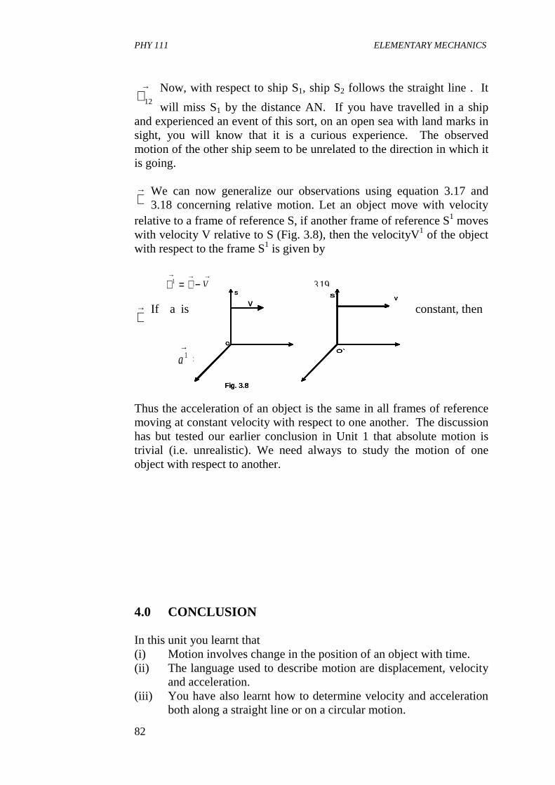
PHY 111 ELEMENTARY MECHANICS
82
Now, with respect to ship S1, ship S2 follows the straight line . It
will miss S1 by the distance AN. If you have travelled in a ship and experienced an event of this sort, on an open sea with land marks in sight, you will know that it is a curious experience. The observed motion of the other ship seem to be unrelated to the direction in which it is going.
We can now generalize our observations using equation 3.17 and 3.18 concerning relative motion. Let an object move with velocity
relative to a frame of reference S, if another frame of reference S1 moves with velocity V relative to S (Fig. 3.8), then the velocityV1 of the object with respect to the frame S1 is given by
If a is constant, then
Thus the acceleration of an object is the same in all frames of reference moving at constant velocity with respect to one another. The discussion has but tested our earlier conclusion in Unit 1 that absolute motion is trivial (i.e. unrealistic). We need always to study the motion of one object with respect to another. 4.0 CONCLUSION In this unit you learnt that (i) Motion involves change in the position of an object with time. (ii) The language used to describe motion are displacement, velocity
and acceleration. (iii) You have also learnt how to determine velocity and acceleration
both along a straight line or on a circular motion.
∨→
12
∨→
∨ = ∨ −→ → →
1 319V .
∨→
a a1 3 20→ →
= .
S
Fig. 3.8
O
O`
VS`
vS
Fig. 3.8
O
O`
VS`S
Fig. 3.8
O
O`
VS`S
Fig. 3.8
O
O`
VS`
v
PHY 111 ELEMENTARY MECHANICS
83
(iv) You have also learnt about relative motion and how it is determined.
5.0 SUMMARY What you have learnt in this unit are (i) A body is said to be in motion if it changes position with time (ii) A frame of reference is required to determine any kind of
variation of position with time. (iii) That the instantaneous velocity and instantaneous acceleration of the
particle are:
(iv) For a particle performing uniform circular motion, the instantaneous velocity is always directed along the tangent and. Has magnitude v = T where r is the radius of the circle and � is the angular speed if the particle.
(v) That the instantaneous acceleration is directed towards the centre,
and has magnitude
(vi) That motion is relative (vii) That the relative position and velocity of a particle P with respect
to a particle, Q are given as
∨ = = ∨ + ∨ + ∨
∨ = ∨ = ∨ =
=∨
− = + +
= = = =
= =
→→
→→ →
→→ →
→→
→
d r
dti i k
wheredx
dt
dy
dt
dz
dt
andad
dt
d r
dta i a j a k
where ad v
dt
d x
dta
d v
dt
d y
dt
ad v
dt
d z
dt
x y z
x y z
x y z
xy
y
zz
, ,
,
2
2
2
2
2
2
2
2
ar
rR
→=
∨=
22ω
PHY 111 ELEMENTARY MECHANICS
84
where rP and rQ are the position vectors of P and Q in a given frame of reference. VP and VQ are the velocities of P and Q in this frame. 6.0 TUTOR MARKED ASSIGNMENTS (TMAS) 1. Why is the statement “I am moving ” meaningless? 2. An automobile A, traveling relative to the earth at 65km h-1 on a
straight level road, is ahead of an Okada cyclist (motor cyclist) B traveling in the same direction at 80km h-1 What is the velocity of B relative to A?
3. A small body of mass 0.2 kg moves uniformly in a circle on a horizontal frictionless surface, attached by a cord 0.2m long to a pin set in the surface. If the body makes two complete revolutions per second, find the force P exerted on it by the cord.
7.0 REFERENCES AND FURTHER READING Spiegel, M. R. (1959). Vector Analysis-Schaum’s Series, McGraw Hill
Book Company, New York. Stroud, K. A. (1995). Engineering Mathematics-Fourth Edition London,
Macmillan Press Ltd. Das Sarma, J. M.. (1978). An Introduction to Higher Secondary Physics
India, Modern Book Agency Private Ltd. Fishbane, P. M., Gasiorowicz, S and Thronton S. T. (1996). Physics for
Scientist and Engineer 2rd Ed. Vol. 1 New Jersey, in Prentice Hall.
Indira Gandi National Open University School of Sciences. PHE 01,
Elementary Mechanics.
r r r andQ P p Q
QP p Q
→ → →
→ → →
= −
∨ = ∨ − ∨
PHY 111 ELEMENTARY MECHANICS
85
UNIT 2 FORCE CONTENTS 1.0 Introduction 2.0 Objective 3.0 Main Body
3.1 Definition of Force 3.1.1 Graphical representation of force 3.1.2 Equilibrium of forces
3.2 Newton’s laws of motion 4.0 Conclusion 5.0 Summary 6.0 Tutor Marked Assignment (TMA) 7.0 References and Further Reading 1.0 INTRODUCTION In the last two Units we explored the parameters that describe motion such as velocity and acceleration. Such a description is called Kinematics. Kinematics alone cannot predict the possible motion of an object. In this Unit, we shall look at other things that cause changes in motion of an object. The studies of the causes of motion are called Dynamics. A scientist called Sir Isaac Newton described the laws that govern motion in 1687. These are based on careful and extensive observations of motion and its changes. It may interest you to know that these laws actually provide an accurate description of motion of all objects, whether they are small or big, whether they are simple or complicated, though with minute exceptions. These exceptions include motions within the atoms and motions near the speed of light (300,000km s-1). I would like you to note that Newton’s laws represent tremendous achievement in their simplicity and breadth of what they cover. We use Newton’s law to calculate the motion of a body given the force acting on it.
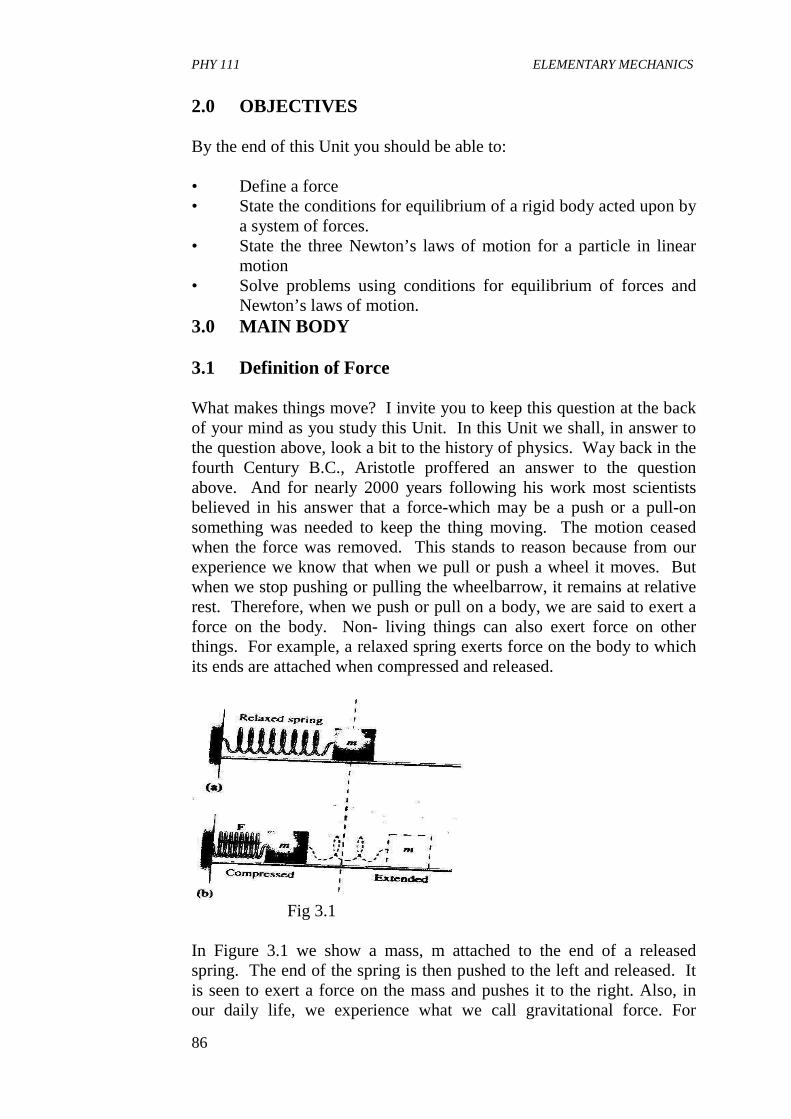
PHY 111 ELEMENTARY MECHANICS
86
2.0 OBJECTIVES By the end of this Unit you should be able to: • Define a force • State the conditions for equilibrium of a rigid body acted upon by
a system of forces. • State the three Newton’s laws of motion for a particle in linear
motion • Solve problems using conditions for equilibrium of forces and
Newton’s laws of motion. 3.0 MAIN BODY 3.1 Definition of Force What makes things move? I invite you to keep this question at the back of your mind as you study this Unit. In this Unit we shall, in answer to the question above, look a bit to the history of physics. Way back in the fourth Century B.C., Aristotle proffered an answer to the question above. And for nearly 2000 years following his work most scientists believed in his answer that a force-which may be a push or a pull-on something was needed to keep the thing moving. The motion ceased when the force was removed. This stands to reason because from our experience we know that when we pull or push a wheel it moves. But when we stop pushing or pulling the wheelbarrow, it remains at relative rest. Therefore, when we push or pull on a body, we are said to exert a force on the body. Non- living things can also exert force on other things. For example, a relaxed spring exerts force on the body to which its ends are attached when compressed and released.
Fig 3.1 In Figure 3.1 we show a mass, m attached to the end of a released spring. The end of the spring is then pushed to the left and released. It is seen to exert a force on the mass and pushes it to the right. Also, in our daily life, we experience what we call gravitational force. For
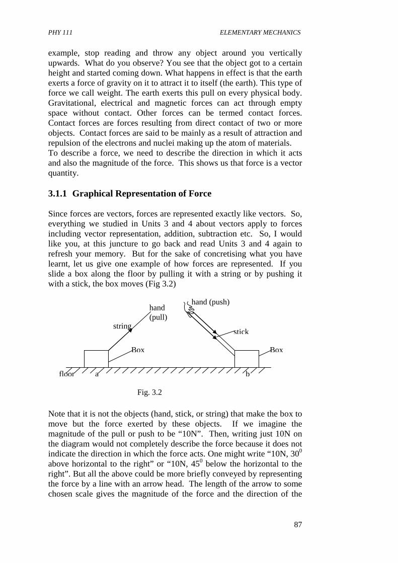
PHY 111 ELEMENTARY MECHANICS
87
example, stop reading and throw any object around you vertically upwards. What do you observe? You see that the object got to a certain height and started coming down. What happens in effect is that the earth exerts a force of gravity on it to attract it to itself (the earth). This type of force we call weight. The earth exerts this pull on every physical body. Gravitational, electrical and magnetic forces can act through empty space without contact. Other forces can be termed contact forces. Contact forces are forces resulting from direct contact of two or more objects. Contact forces are said to be mainly as a result of attraction and repulsion of the electrons and nuclei making up the atom of materials. To describe a force, we need to describe the direction in which it acts and also the magnitude of the force. This shows us that force is a vector quantity. 3.1.1 Graphical Representation of Force Since forces are vectors, forces are represented exactly like vectors. So, everything we studied in Units 3 and 4 about vectors apply to forces including vector representation, addition, subtraction etc. So, I would like you, at this juncture to go back and read Units 3 and 4 again to refresh your memory. But for the sake of concretising what you have learnt, let us give one example of how forces are represented. If you slide a box along the floor by pulling it with a string or by pushing it with a stick, the box moves (Fig 3.2) Note that it is not the objects (hand, stick, or string) that make the box to move but the force exerted by these objects. If we imagine the magnitude of the pull or push to be “10N”. Then, writing just 10N on the diagram would not completely describe the force because it does not indicate the direction in which the force acts. One might write “10N, 300
above horizontal to the right” or “10N, 450 below the horizontal to the right”. But all the above could be more briefly conveyed by representing the force by a line with an arrow head. The length of the arrow to some chosen scale gives the magnitude of the force and the direction of the
b a floor
string
hand (pull)
Box Box
stick
hand (push)
Fig. 3.2
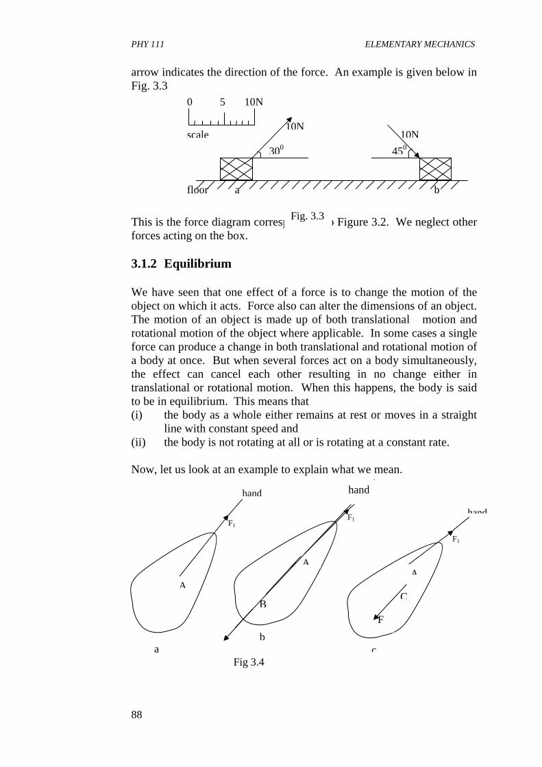
PHY 111 ELEMENTARY MECHANICS
88
arrow indicates the direction of the force. An example is given below in Fig. 3.3 This is the force diagram corresponding to Figure 3.2. We neglect other forces acting on the box. 3.1.2 Equilibrium We have seen that one effect of a force is to change the motion of the object on which it acts. Force also can alter the dimensions of an object. The motion of an object is made up of both translational motion and rotational motion of the object where applicable. In some cases a single force can produce a change in both translational and rotational motion of a body at once. But when several forces act on a body simultaneously, the effect can cancel each other resulting in no change either in translational or rotational motion. When this happens, the body is said to be in equilibrium. This means that (i) the body as a whole either remains at rest or moves in a straight
line with constant speed and (ii) the body is not rotating at all or is rotating at a constant rate. Now, let us look at an example to explain what we mean.
scale
10N 5 0
450 300
10N 10N
b a floor
Fig. 3.3
hand
F1
A
a
hand
F1
A
c
F
C
hand
F1
A
b
B
hand
Fig 3.4
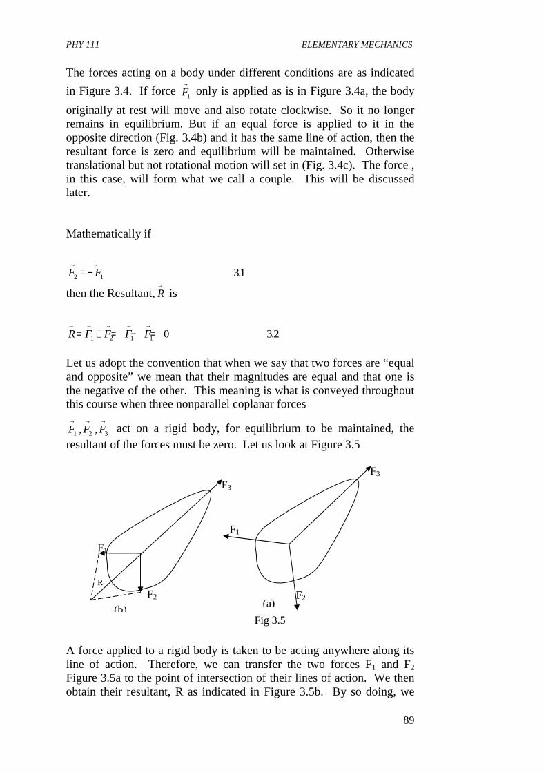
PHY 111 ELEMENTARY MECHANICS
89
The forces acting on a body under different conditions are as indicated
in Figure 3.4. If force F1
→ only is applied as is in Figure 3.4a, the body
originally at rest will move and also rotate clockwise. So it no longer remains in equilibrium. But if an equal force is applied to it in the opposite direction (Fig. 3.4b) and it has the same line of action, then the resultant force is zero and equilibrium will be maintained. Otherwise translational but not rotational motion will set in (Fig. 3.4c). The force , in this case, will form what we call a couple. This will be discussed later. Mathematically if
F F2 1 31→ →
= − .
then the Resultant,R→
is
R F F F F→ → → → →
= + = − =1 2 1 1 0 32. Let us adopt the convention that when we say that two forces are “equal and opposite” we mean that their magnitudes are equal and that one is the negative of the other. This meaning is what is conveyed throughout this course when three nonparallel coplanar forces
F F F1 2 3
→ → →, , act on a rigid body, for equilibrium to be maintained, the
resultant of the forces must be zero. Let us look at Figure 3.5 A force applied to a rigid body is taken to be acting anywhere along its line of action. Therefore, we can transfer the two forces F1 and F2 Figure 3.5a to the point of intersection of their lines of action. We then obtain their resultant, R as indicated in Figure 3.5b. By so doing, we
F3
F2
F1
Fig 3.5
(a)
R
F3
F2
F1
(b)
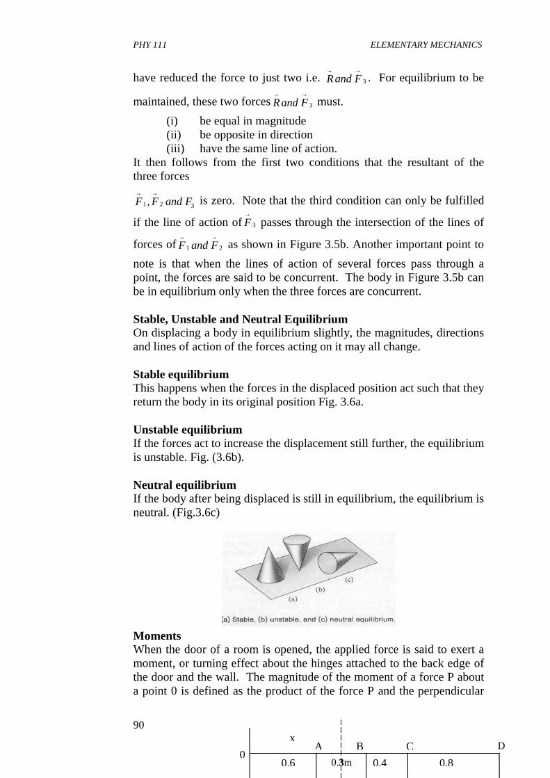
PHY 111 ELEMENTARY MECHANICS
90
have reduced the force to just two i.e. Rand F→ →
3 . For equilibrium to be
maintained, these two forcesRand F→ →
3 must.
(i) be equal in magnitude (ii) be opposite in direction (iii) have the same line of action.
It then follows from the first two conditions that the resultant of the three forces
F F and F→ →
1 2 3, is zero. Note that the third condition can only be fulfilled
if the line of action ofF→
3 passes through the intersection of the lines of
forces ofF and F→ →
1 2 as shown in Figure 3.5b. Another important point to
note is that when the lines of action of several forces pass through a point, the forces are said to be concurrent. The body in Figure 3.5b can be in equilibrium only when the three forces are concurrent. Stable, Unstable and Neutral Equilibrium On displacing a body in equilibrium slightly, the magnitudes, directions and lines of action of the forces acting on it may all change. Stable equilibrium This happens when the forces in the displaced position act such that they return the body in its original position Fig. 3.6a. Unstable equilibrium If the forces act to increase the displacement still further, the equilibrium is unstable. Fig. (3.6b). Neutral equilibrium If the body after being displaced is still in equilibrium, the equilibrium is neutral. (Fig.3.6c)
Moments When the door of a room is opened, the applied force is said to exert a moment, or turning effect about the hinges attached to the back edge of the door and the wall. The magnitude of the moment of a force P about a point 0 is defined as the product of the force P and the perpendicular
0.80.40.3m 0.6
A B C D 0
x
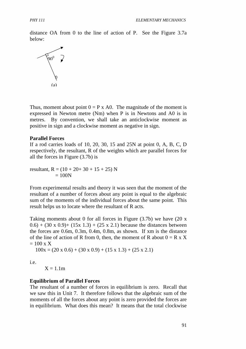
PHY 111 ELEMENTARY MECHANICS
91
distance OA from 0 to the line of action of P. See the Figure 3.7a below: Thus, moment about point 0 = P x A0. The magnitude of the moment is expressed in Newton metre (Nm) when P is in Newtons and A0 is in metres. By convention, we shall take an anticlockwise moment as positive in sign and a clockwise moment as negative in sign. Parallel Forces If a rod carries loads of 10, 20, 30, 15 and 25N at point 0, A, B, C, D respectively, the resultant, R of the weights which are parallel forces for all the forces in Figure (3.7b) is resultant, R = (10 + 20+ 30 + 15 + 25) N = 100N From experimental results and theory it was seen that the moment of the resultant of a number of forces about any point is equal to the algebraic sum of the moments of the individual forces about the same point. This result helps us to locate where the resultant of R acts. Taking moments about 0 for all forces in Figure (3.7b) we have (20 x 0.6) + (30 x 0.9)+ (15x 1.3) + (25 x 2.1) because the distances between the forces are 0.6m, 0.3m, 0.4m, 0.8m, as shown. If xm is the distance of the line of action of R from 0, then, the moment of R about 0 = R x X = 100 x X � 100x = (20 x 0.6) + (30 x 0.9) + (15 x 1.3) + (25 x 2.1) i.e. X = 1.1m Equilibrium of Parallel Forces The resultant of a number of forces in equilibrium is zero. Recall that we saw this in Unit 7. It therefore follows that the algebraic sum of the moments of all the forces about any point is zero provided the forces are in equilibrium. What does this mean? It means that the total clockwise
0
900
(a)
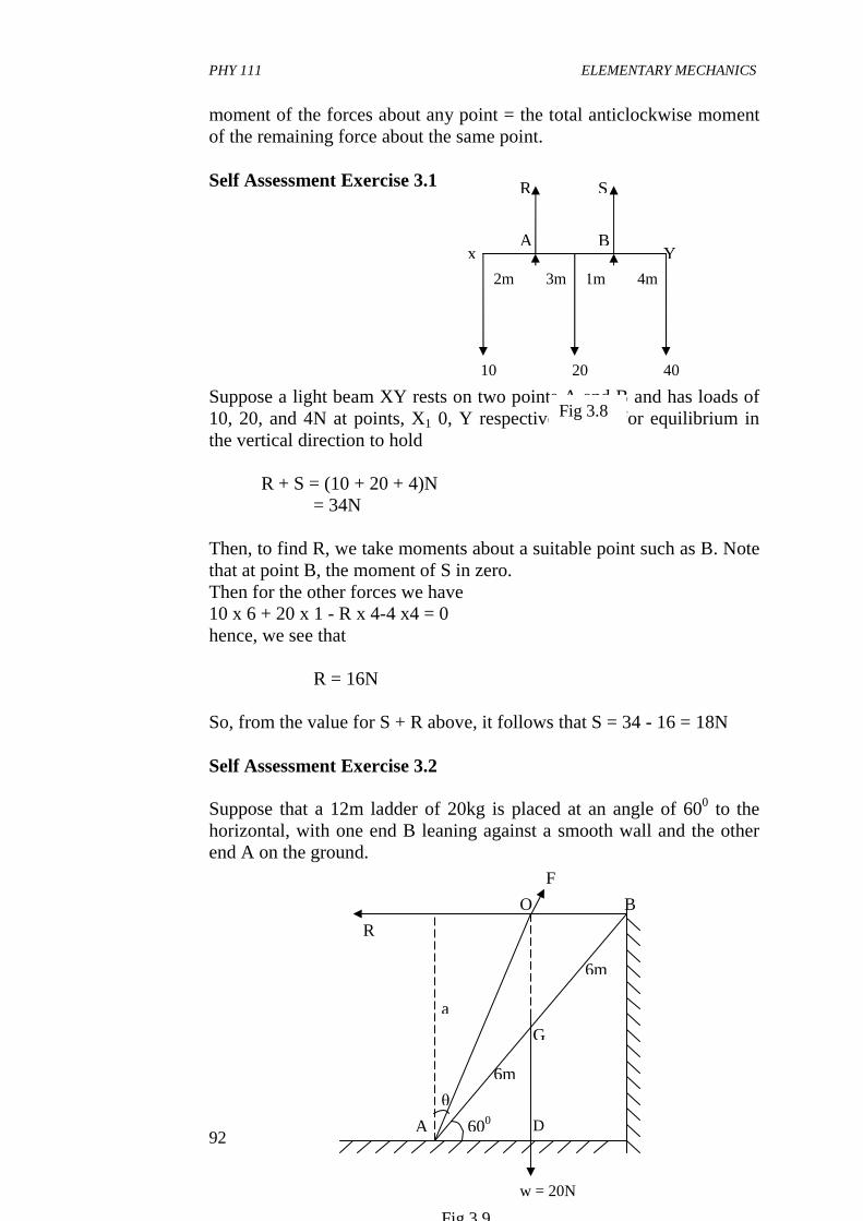
PHY 111 ELEMENTARY MECHANICS
92
moment of the forces about any point = the total anticlockwise moment of the remaining force about the same point. Self Assessment Exercise 3.1 Suppose a light beam XY rests on two points A and B and has loads of 10, 20, and 4N at points, X1 0, Y respectively, then for equilibrium in the vertical direction to hold R + S = (10 + 20 + 4)N = 34N Then, to find R, we take moments about a suitable point such as B. Note that at point B, the moment of S in zero. Then for the other forces we have 10 x 6 + 20 x 1 - R x 4-4 x4 = 0 hence, we see that R = 16N So, from the value for S + R above, it follows that S = 34 - 16 = 18N Self Assessment Exercise 3.2 Suppose that a 12m ladder of 20kg is placed at an angle of 600 to the horizontal, with one end B leaning against a smooth wall and the other end A on the ground.
A
Fig 3.8
x
R S
Y B
20
4m 1m 3m 2m
10 40
6m
600
θ
6m
a
O B
G
R
A D
w = 20N
F
Fig 3.9
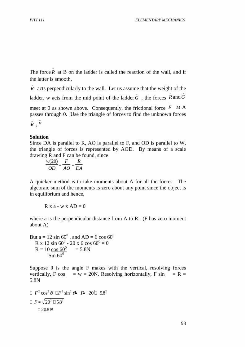
PHY 111 ELEMENTARY MECHANICS
93
The forceR→
at B on the ladder is called the reaction of the wall, and if the latter is smooth,
R→
acts perpendicularly to the wall. Let us assume that the weight of the
ladder, w acts from the mid point of the ladderG→
, the forces R→
andG→
meet at 0 as shown above. Consequently, the frictional force F→
at A passes through 0. Use the triangle of forces to find the unknown forces
R→
,F→
Solution Since DA is parallel to R, AO is parallel to F, and OD is parallel to W, the triangle of forces is represented by AOD. By means of a scale drawing R and F can be found, since
w
OD
F
AO
R
DA
( )20= =
A quicker method is to take moments about A for all the forces. The algebraic sum of the moments is zero about any point since the object is in equilibrium and hence, R x a - w x AD = 0 where a is the perpendicular distance from A to R. (F has zero moment about A) But a = 12 sin 600 , and AD = 6 cos 600 � R x 12 sin 600 - 20 x 6 cos 600 = 0 � R = 10 cos 600 = 5.8N Sin 600
Suppose θ is the angle F makes with the vertical, resolving forces vertically, F cos � = w = 20N. Resolving horizontally, F sin � = R = 5.8N ∴ + = = +
∴ = +=
F F F
F
N
2 2 2 2 2 2
2 2
20 58
20 58
208
cos sin .
.
.
θ θ
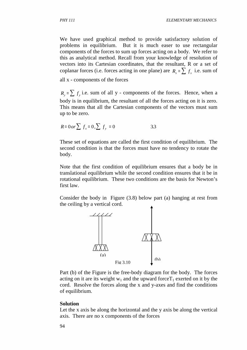
PHY 111 ELEMENTARY MECHANICS
94
We have used graphical method to provide satisfactory solution of problems in equilibrium. But it is much easer to use rectangular components of the forces to sum up forces acting on a body. We refer to this as analytical method. Recall from your knowledge of resolution of vectors into its Cartesian coordinates, that the resultant, R or a set of coplanar forces (i.e. forces acting in one plane) are R fx x= ∑ i.e. sum of
all x - components of the forces R fy y= ∑ i.e. sum of all y - components of the forces. Hence, when a
body is in equilibrium, the resultant of all the forces acting on it is zero. This means that all the Cartesian components of the vectors must sum up to be zero. R or f fx y= = =∑ ∑0 0 0 33, .
These set of equations are called the first condition of equilibrium. The second condition is that the forces must have no tendency to rotate the body. Note that the first condition of equilibrium ensures that a body be in translational equilibrium while the second condition ensures that it be in rotational equilibrium. These two conditions are the basis for Newton’s first law. Consider the body in Figure (3.8) below part (a) hanging at rest from the ceiling by a vertical cord. Part (b) of the Figure is the free-body diagram for the body. The forces acting on it are its weight w1 and the upward forceT1 exerted on it by the cord. Resolve the forces along the x and y-axes and find the conditions of equilibrium. Solution Let the x axis be along the horizontal and the y axis be along the vertical axis. There are no x components of the forces
(a)
Fig 3.10 (b)

PHY 111 ELEMENTARY MECHANICS
95
∴ =∑ f x 0
The y -component of the forces are W1 and T1. For equilibrium to hold,
f y =∑ 0. This means that
T w f
T w first law
y1 1
1 1
0− = =
∴ −∑
( )
Now for their line of actions to be the same, the centre of gravity must lie vertically below the point where the cord is attached. Self Assessment Exercise 3.2 In the Figure below a block of weight w hangs from a cord which is knotted at 0 to two other cords fastened to the ceiling. Find the tensions in these three cords. The weight of the cords are taken to be negligible. Solution If we have to apply the conditions of equilibrium to find an unknown force, then we must consider a body in equilibrium. In our problem, the hanging box is in equilibrium as shown in the diagram (Fig 3.11) The tension in the vertical cord supporting the block is equal to the weight of the block. Note that the inclined cords do not exert forces on the block, but they do act on the knot at 0. So, we consider the knot as a particle in equilibrium with negligible weight. In the free-body diagrams for the knot and the block shown above, T1, T2 and T3 represent the forces extended on the knot by the three cords. T1, T2 and T3 are the reactions to these forces.
(a)
θ2 θ1 B A
w
o
T1|
T1
T2
T2|
T3
T3|
w
(b)
B A
Fig 3.11
ox
y
θ3 θ2
T3
T2
T1
Forces on the knot
Fig 3.12
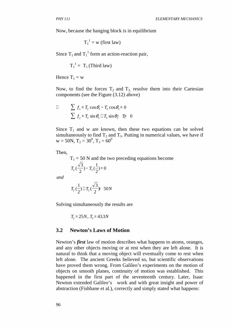
PHY 111 ELEMENTARY MECHANICS
96
Now, because the hanging block is in equilibrium T1
1 = w (first law) Since T1
and T11 form an action-reaction pair,
T1
1 = T1 (Third law)
Hence T1 = w Now, to find the forces T2
and T3, resolve them into their Cartesian components (see the Figure (3.12) above) ∴ = − =
= + − =
∑∑
f T T
f T T T
x
y
2 2 3 3
2 2 3 3 1
0
0
cos cos
sin sin
θ θ
θ θ
Since T1 and w are known, then these two equations can be solved simultaneously to find T2 and T3. Putting in numerical values, we have if w = 50N, T2 = 300, T3 = 600 Then, T1 = 50 N and the two preceding equations become
T T
and
T T N
2 3
2 3
3
2
1
20
1
2
3
250
( ) ( )
( ) ( )
− =
+ =
Solving simultaneously the results are
T N T N2 325 433= =, .
3.2 Newton’s Laws of Motion Newton’s first law of motion describes what happens to atoms, oranges, and any other objects moving or at rest when they are left alone. It is natural to think that a moving object will eventually come to rest when left alone. The ancient Greeks believed so, but scientific observations have proved them wrong. From Galileo’s experiments on the motion of objects on smooth planes, continuity of motion was established. This happened in the first part of the seventeenth century. Later, Isaac Newton extended Galileo’s work and with great insight and power of abstraction (Fishbane et al.), correctly and simply stated what happens:
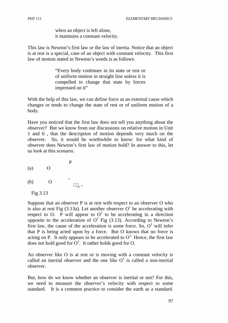
PHY 111 ELEMENTARY MECHANICS
97
when an object is left alone, it maintains a constant velocity. This law is Newton’s first law or the law of inertia. Notice that an object is at rest is a special, case of an object with constant velocity. This first law of motion stated in Newton’s words is as follows:
“Every body continues in its state or rest or of uniform motion in straight line unless it is compelled to change that state by forces impressed on it”
With the help of this law, we can define force as an external cause which changes or tends to change the state of rest or of uniform motion of a body. Have you noticed that the first law does not tell you anything about the observer? But we know from our discussions on relative motion in Unit 1 and 6 , that the description of motion depends very much on the observer. So, it would be worthwhile to know: for what kind of observer does Newton’s first law of motion hold? In answer to this, let us look at this scenario. P (a) O
(b) O ←
→O| Fig 3.13
Suppose that an observer P is at rest with respect to an observer O who is also at rest Fig (3.13a). Let another observer O1 be accelerating with respect to O. P will appear to O1 to be accelerating in a direction opposite to the acceleration of O1 Fig (3.13). According to Newton’s first law, the cause of the acceleration is some force. So, O1 will infer that P is being acted upon by a force. But O knows that no force is acting on P. It only appears to be accelerated to O1. Hence, the first law does not hold good for O1. It rather holds good for O. An observer like O is at rest or is moving with a constant velocity is called an inertial observer and the one like O1 is called a non-inertial observer. But, how do we know whether an observer is inertial or not? For this, we need to measure the observer’s velocity with respect to some standard. It is a common practice to consider the earth as a standard.
PHY 111 ELEMENTARY MECHANICS
98
This we also saw in our Unit 1 of this course. Now, the place where one is performing one’s experiment have an acceleration towards the polar axis due to the daily rotation of the earth. Again the centre of the earth has an acceleration towards the sun owing to its yearly motion around the sun. The sun also has an acceleration towards the centre of the Galaxy, and so on. Hence the search for an absolute inertial frame is unending. So, we modify the definition of the inertial observer. We say that:
two observers are inertial with each either if they are either at rest or in uniform motion with respect to one another. If an observer has an acceleration with respect to another, then, they are non-inertial with respect to one another.
Thus a car moving with a constant velocity and a man standing on a road are inertial with respect to one another while a car in the process of gathering speed, and the man standing are non- inertial with respect to each other. The first law tells you how to detect the presence or absence of force on a body. In a sense, it tells you what a force does-it produces acceleration (either positive or negative ) in a body. But the first law does not give quantitative, measurable definition of force. This is what the second law does. It gives quantitative, measurable definition of force. Newton’s Second Law of Motion If you are struck by a very fast moving hockey ball you get injured, but if you are hit by a flower moving with the same velocity as that of the ball, you do not feel perturbed at all. However, if you are struck by a slower ball, the injury is less serious. This indicates that any kind of impact made by an object depends on two things viz.
(i) its mass and (ii) its velocity
Hence, Newton felt the necessity of defining the product of mass and velocity which later came to be known as linear momentum. Mathematically speaking, linear momentum is given by
P m→ →
= ∨ 34.
PHY 111 ELEMENTARY MECHANICS
99
Thus P is a vector quantity in the direction of velocity. The introduction of the above quantity paved the way for stating the second law, which in Newton’s words are as follows:
“The change of motion of an object is proportional to the force impressed; and is made in the direction of the straight line in which the force is impressed ”
By “change of motion,” Newton meant the rate of change of momentum with time. So mathematically we have
Fd P
dt
or
F kd P
dt
→→
→→
∝
=
( )
( ).35
where F→
is the impressed force ark k is a constant of proportionality. The differential operator d
dt indicates the rate of change with time. Now, if the mass of the body
remains constant (i.e. neither the body is gaining in mass like a conveyor belt nor it is disintergrating like a rocket ), then
d p
dt
d mv
dtm
d v
dtma
→ →→
= = =( )
where
ad
dt
→→
=∨
= the acceleration of the body.
Thus from Eqn. 3.5 we get
F kma and a
F kma b
→ →
→
=
=
36
36
.
.
We saw earlier that the need for a second law was felt in other to provide a quantitative definition of force. Something must be done with
PHY 111 ELEMENTARY MECHANICS
100
the constant k. We have realised that the task of a force F→
acting on a
body of mass m is to produce in it an accelerations a→
. Hence, anything
appearing in the expression for force other than m anda→
must be a pure number, i.e. k is a pure number. So we can afford to make a choice for its numerical value. We define unit of force as one which produces unit acceleration in its direction when it acts on a unit mass. So we obtain from Eqn. (3.6b) that 1 = k . 1.1 or k = 1. Thus, Eqn. (3.5), and (3.6) take the form
Fd p
dtand a
→→
= 37.
for constant mass F ma→ →
= 3.7b Now, we know from Unit 6 that if the position vector of a particle isr
→ at
a time t then its velocity ∨→
and accelerationa→
are given by equations.
∨ = =∨
=∨→
→→
→
→d r
dtand a
t
d
dttlim( )∆
∆∆0
Substituting for
a and→ →
∨ in Eqn. 3.7 we get
F md
dtm
d
dt
dr
dt
or
Fd r
dt
→
→→
=∨
=
=
( )
.2
2 38
Eqn. 3.8 is a second order differential equation inr
→ . If we know the
forceF→
acting on a body of mass m, we can integrate Eqn. (3.8) to
determine r as a function of t. The functionr t→
( ) would give us the path
of the particle. Since Eqn. (3.8) is of second order, we shall come across two constants of integration. So we require two initial conditions to work out a solution of this equation. Conversely, if we know the path or trajectory of an accelerating particle, we can use Eqn. (3.8) to determine
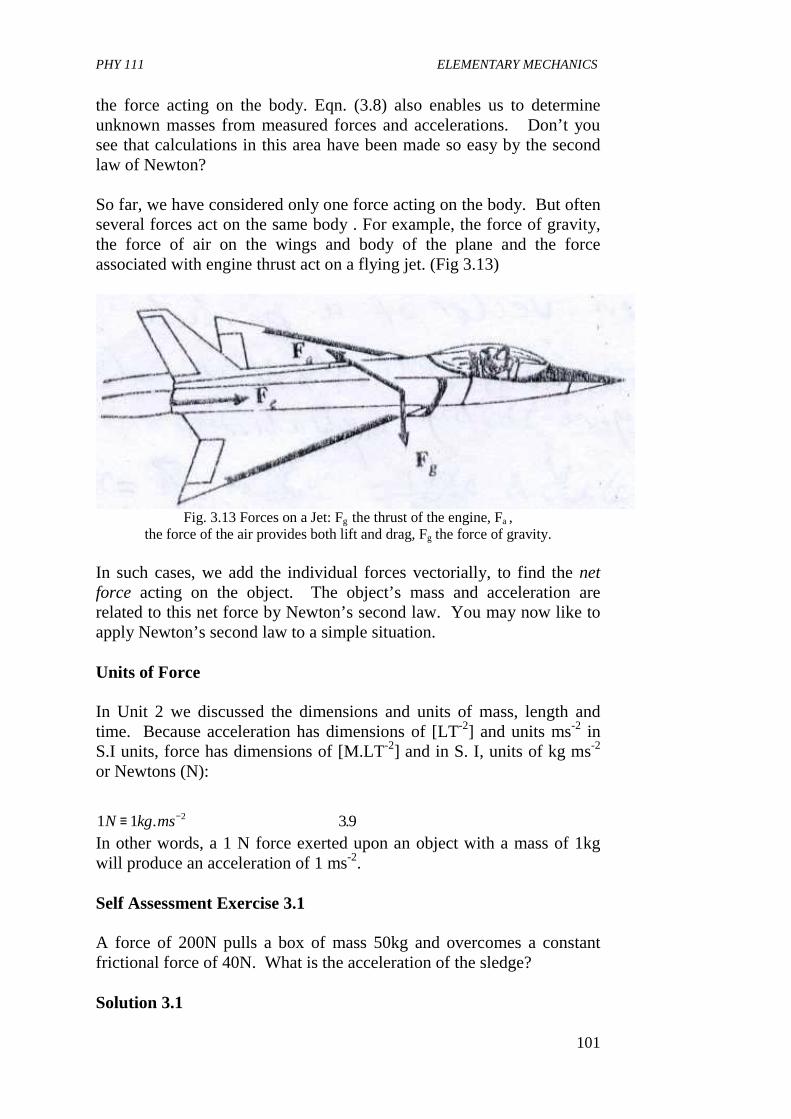
PHY 111 ELEMENTARY MECHANICS
101
the force acting on the body. Eqn. (3.8) also enables us to determine unknown masses from measured forces and accelerations. Don’t you see that calculations in this area have been made so easy by the second law of Newton? So far, we have considered only one force acting on the body. But often several forces act on the same body . For example, the force of gravity, the force of air on the wings and body of the plane and the force associated with engine thrust act on a flying jet. (Fig 3.13)
Fig. 3.13 Forces on a Jet: Fg the thrust of the engine, Fa ,
the force of the air provides both lift and drag, Fg the force of gravity. In such cases, we add the individual forces vectorially, to find the net force acting on the object. The object’s mass and acceleration are related to this net force by Newton’s second law. You may now like to apply Newton’s second law to a simple situation. Units of Force In Unit 2 we discussed the dimensions and units of mass, length and time. Because acceleration has dimensions of [LT-2] and units ms-2 in S.I units, force has dimensions of [M.LT-2] and in S. I, units of kg ms-2 or Newtons (N): 1 1 392N kg ms≡ −. . In other words, a 1 N force exerted upon an object with a mass of 1kg will produce an acceleration of 1 ms-2. Self Assessment Exercise 3.1 A force of 200N pulls a box of mass 50kg and overcomes a constant frictional force of 40N. What is the acceleration of the sledge? Solution 3.1
PHY 111 ELEMENTARY MECHANICS
102
The Resultant force, F = 200N - 40N = 160N from
F ma x a
aN
kg
ms
or a N
= =
∴ =
==
−
50
160
50
32
32
2.
.
Self Assessment Exercise 3.2 An object of mass 2.0kg is attached to the hook of a spring balance, and the latter is suspended vertically from the roof of a lift. What is the reading on the spring balance when the lift is (i) ascending with an acceleration of 20cm s-2 (ii) descending with an acceleration of 10cms-2 Solution 3.2 (i) The object is acted upon by two forces (a) The tension TN in the spring-balance, which acts upwards (b) Its weight 20N which acts downwards. Since the object moves upwards , T is greater than 20N. Hence the resultant or net force, F acting on the object is (T - 20) N approximately Now F = ma where a is the acceleration (i) T (T - 20) N = 2kg x 0.2 ms-2
� T = 20. 4 N Answer
(ii) When the lift descends with an acceleration of 10 cm s-2 or 0.1ms-2, the weight, 20 N is now greater than T1 N the tension in the spring balance.
(iii) 2 Resultant force = (20 - T1)N = 20 -T1
2 F = (20 - T)N = ma = 2kg x 0.1ms-2 2 T = 20 - 0.2 = 19.8 N
Answer Newton’s Third Law of Motion So far we have been trying to understand how and why a single body moves. We have identified force as the cause of change in the motion of a body. But how does one exert a force on his body? Inevitably, there is
PHY 111 ELEMENTARY MECHANICS
103
an agent that makes this possible. Very often, your hands or feet are the agents. In football, your feet bring the ball into motion. Thus, forces arise from interactions between systems. This fact is made clear in Newton’s third law of motion. To put it in his own words:
“ To every action there is an equal and opposite reaction.”
Here the words ‘action’ and ‘reaction’ means forces as defined by the first and second laws. If a body A exerts a force, FAB on a body B, then the body B in turn exerts a force FBA on A, such that FAB = -FBA So, we have FAB + FBA = 0 Notice that Newton’s third law deals with two forces, each acting on a different body. You may now like to work out an exercise based on the third law. Self Assessment Exercise 3.3 (a) When a footballer kicks the ball, the ball and the man experience
forces of the same magnitude but in opposite directions according to the third law. The ball moves but the man does not move. Why?
(b) The earth attracts an apple with a force of magnitude F. What is the magnitude of the force with which the apple attracts the earth? The apple moves towards the earth. Why does not the reverse happen?
Solution (3a) The reaction force acts on the man. Due to the large
mass(inertia) of the man the force is not able to make him move. (b) Apple also attracts the earth with a force of magnitude F. The
acceleration of the apple and the earth are, respectively, F/ma and F/m� , where ma and m are the masses of the apple and the earth, respectively. Since m>>ma F/m� << F/ma. Hence the earth does not move appreciably.
Newton’s laws of motion provide a means of understanding most aspects of motion. In the next Unit, we shall study impulse and momentum. 4.0 CONCLUSION In this unit, you have learnt that • Objects are kept in motion as a result of externally implied forces
on them.
PHY 111 ELEMENTARY MECHANICS
104
• Even inanimate objects can exert forces • A body can only be in static or dynamic equilibrium if all the
forces acting on it cancel each other. • The three Newton’s laws of motion are applied in solving
problems relating to motion and forces that keep objects in motion
5.0 SUMMARY What you have learnt in this unit are: • that the study of the parametres that describe linear motion is
called kinematics • that the studies of the causes of motion is called dynamics • that force is a push or a pull exerted on a body by another body. • that there are gravitational forces and contact forces • that forces can be represented graphically just like vectors • that the conditions for equilibrium when a system of forces are
acting on a rigid body are: (i) the resultant of all the forces sum up to zero
i.e.
(iii) The forces must have no tendency to rotate the body.
The three Newton’s laws express the dynamics of motion how forces acting between objects determine the subsequent motion of those objects. The first law states what happens to an object-moving or at rest when it is left alone. The second law is
F = ma The third law is FBA = - FAB i.e. As regards forces between objects that if A and B interact and forces are acting between them, then by this third law the force an object A due
R F F F
or
R F F Fx y
→
→
= + + =
= + + =∑ ∑∑
1 2 3
2
0
0
..........
PHY 111 ELEMENTARY MECHANICS
105
to object B is FAB and is equal and opposite to the force an object B due to object A which is FBA . • that in S. I, force is measured in Newtons abbreviated N where N
= 1kg ms-2 • Newton’s laws help us to determine the motion of an object if we
know the nature of the forces that act on it. • Conversely, the laws enable us to measure forces acting on an
object by measuring the objects motion. • that observers in reference frames moving with respect to one
another observe the motion of a given object differently. 6.0 TUTOR MARKED ASSIGNMENTS (TMA) (1) Astronauts on the Skylab mission of the 1970s found their masses
by using a chair on which a known force was exerted by a spring. With an astronaut strapped in the chair, the 15kg chair underwent an acceleration of 2.04 x10⁻²ms-2 when the spring force was 2.07N. What was the astronaut’s mass?
(2) Three children each tug at the same plank. All the forces are in
the horizontal plane. The three forces on the plank have the vectorial decomposition F1 = -5k units, F2 = 5i units and F3 = (- 5i + 5k) units in terms of their unit vectors. What is the force on the box? What can you say about its consequent motion? Ignore the force of gravity.
(3) A particle of mass m is hung by two lights strings. The ends A
and B are held by hands. The strings OA and OB make angles 2 with the vertical. Find the values of T and T1 in terms of m and T. T is tension in hand A and T1 is tension in hand B.
7.0 REFERENCES AND FURTHER READING Indira Gandi National Open University School of Sciences. PHE -01,
Elementary Mechanics-Concepts in Mechanics 1. Sears, F. W, Zemansky M, W; Young H:D(1975) College Physical
Fourth Ed. Addison-Wesley Publ. Co. Reading, U. K. Spiegel M. R.(1959) Vector Anaysis-Schaum’s Series, McGraw Hill
Book Company, New York. Stroud K.A. (1995) Engineering Mathematics-Fourth Edition, London,
Macmillian Press Ltd.
PHY 111 ELEMENTARY MECHANICS
106
Das Sarma, J. M. (1978) An Introduction to Higher Secondary Physics,
India Modern Book Agency Private Ltd. Fishbane, P. M. Gasiorowicz, S and Thronton S. T (1996), Physics for
Scientists and Engineers 2nd Ed. Vol. 1 New Jersey, Prentice Hall.
UNIT 3 THE PROJECTILE MOTION CONTENT 1.0 Introduction 2.0 Objectives 3.0 Main Body
3.1 Definition of Projectile Motion 3.2 The Trajectory 3.3 Determining the Parameters of a Projectile Motion.
4.0 Conclusion 5.0 Summary 6.0 Teacher Marked Assignment (T.M.A) 7.0 References and Further Reading. 1.0 INTRODUCTION In the preceding unit we discussed the concepts of force and acceleration. We have applied Newton`s first law in solving problems in equilibrium. In this unit we shall apply Newton’s second law to study projectile motion which is a type of motion in a plain under the influence of the earth`s gravitational field .This science explorers how a body behaves with the resultant force on it is not zero. The chief parameters we shall learn to celebrate here and the range, the maximum height and the time of flight of a particle undergoing projectile motion. 2.0 OBJECTIVES By the end of this unit, you should be able to: • define a projectile motion and a projectile. • state the condition in which a projectile motion is possible • Represent projectile motion graphically. • compute the time of flight, highest point reached, maximum
range attained by a projectile given initial conditions.

PHY 111 ELEMENTARY MECHANICS
107
• Find the angle of projection of a projectile given the necessary parametres.
3.0 MAIN BODY 3.1 Definition of projectile motion To appreciate what you will learn in this unit, find an open space in your neighborhood where you can conveniently throw up a small stone at an angle to the horizontal. Then throw the stone as indicated above. Return to your room and try to sketch the path traced by the stone. Is your sketch similar to Figure (3.1) below? The stone or object thrown into space is called a projectile. The shape of the path traced by the projectile is called a parabola. The maximum; horizontal distance traveled is the range, R. Self Assessment Exercise 3.1 Give more examples of projectile motion. Projectile motion is a good example of motion in 2 dimensions. The initial velocity of projection at an angle � as shown in Figure 3.1 is always resolved into two components there is the vertical component by which it attains some height at any instant of time in the y-axis and some horizontal component by which it covers some range, R in the x-axis. Hence, the motion can be described as a combination of horizontal motion with constant velocity and vertical motion with constant acceleration. Self Assessment Exercise 3.2 Close your book and with a sheet of paper draw again the path traced by the stone you threw outside. Is your representation any better now?
x
y
R
H
VO
θ
Fig 3.1
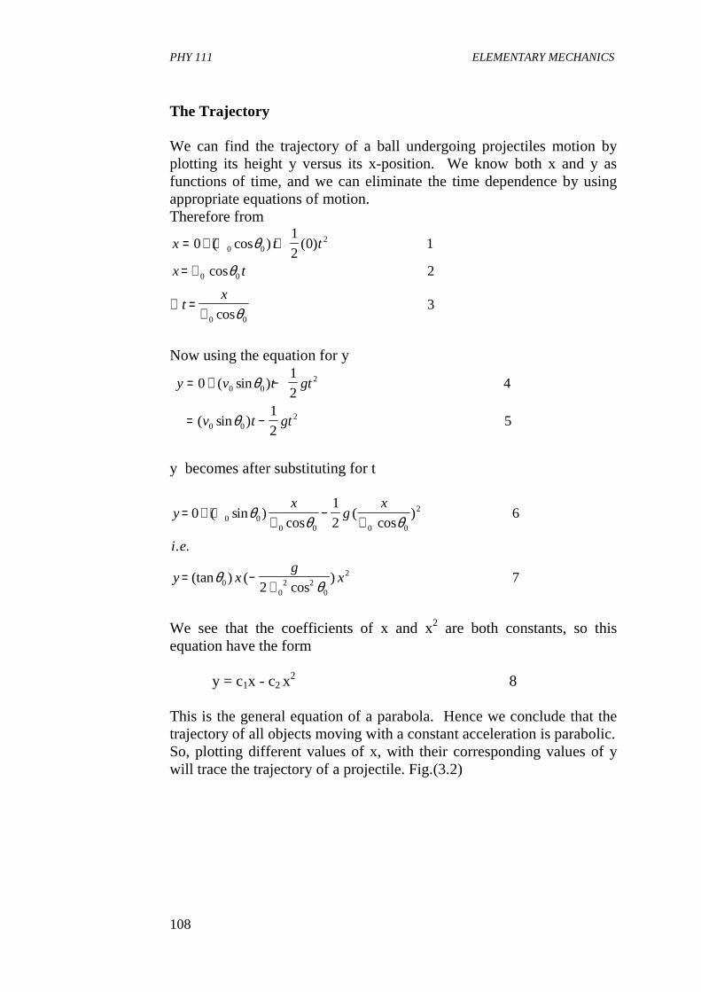
PHY 111 ELEMENTARY MECHANICS
108
The Trajectory We can find the trajectory of a ball undergoing projectiles motion by plotting its height y versus its x-position. We know both x and y as functions of time, and we can eliminate the time dependence by using appropriate equations of motion. Therefore from
x t t
x t
tx
= + ∨ +
= ∨
∴ =∨
01
20 1
2
3
0 02
0 0
0 0
( cos ) ( )
cos
cos
θ
θ
θ
Now using the equation for y
y v t gt
v t gt
= + −
= −
01
24
1
25
0 02
0 02
( sin )
( sin )
θ
θ
y becomes after substituting for t
yx
gx
i e
y xg
x
= + ∨∨
−∨
= −∨
01
26
27
0 00 0 0 0
2
00
2 20
2
( sin )cos
(cos
)
. .
(tan ) (cos
)
θ θ θ
θθ
We see that the coefficients of x and x2 are both constants, so this equation have the form
y = c1x - c2 x2 8
This is the general equation of a parabola. Hence we conclude that the trajectory of all objects moving with a constant acceleration is parabolic. So, plotting different values of x, with their corresponding values of y will trace the trajectory of a projectile. Fig.(3.2)
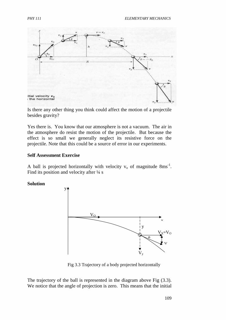
PHY 111 ELEMENTARY MECHANICS
109
Is there any other thing you think could affect the motion of a projectile besides gravity? Yes there is. You know that our atmosphere is not a vacuum. The air in the atmosphere do resist the motion of the projectile. But because the effect is so small we generally neglect its resistive force on the projectile. Note that this could be a source of error in our experiments. Self Assessment Exercise A ball is projected horizontally with velocity vo of magnitude 8ms-1. Find its position and velocity after ¼ s Solution The trajectory of the ball is represented in the diagram above Fig (3.3). We notice that the angle of projection is zero. This means that the initial
VO x
y
θ
y VX=VO
V
Vy
Fig 3.3 Trajectory of a body projected horizontally
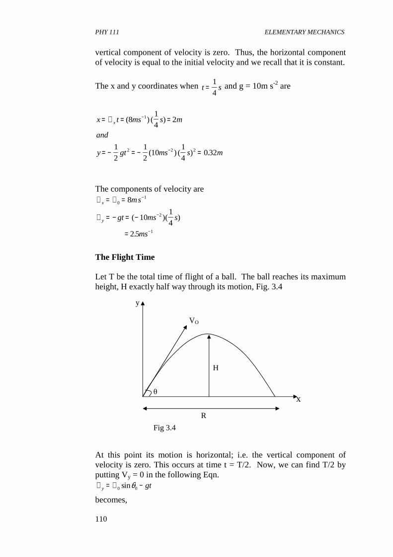
PHY 111 ELEMENTARY MECHANICS
110
vertical component of velocity is zero. Thus, the horizontal component of velocity is equal to the initial velocity and we recall that it is constant.
The x and y coordinates when t s=
1
4 and g = 10m s-2 are
x t ms s m
and
y gt ms s m
x= ∨ = =
= − = − =
−
−
( ) ( )
( ) ( ) .
81
42
1
2
1
210
1
40 32
1
2 2 2
The components of velocity are ∨ = ∨ =
∨ = − = −
=
−
−
−
x
y
ms
gt ms s
ms
01
2
1
8
101
42 5
( )( )
.
The Flight Time Let T be the total time of flight of a ball. The ball reaches its maximum height, H exactly half way through its motion, Fig. 3.4 At this point its motion is horizontal; i.e. the vertical component of velocity is zero. This occurs at time t = T/2. Now, we can find T/2 by putting Vy = 0 in the following Eqn. ∨ = ∨ −y gt0 0sinθ
becomes,
x
y
R
H
VO
θ
Fig 3.4
PHY 111 ELEMENTARY MECHANICS
111
0 = V0 sin 20 - gt so far t = T/2 we have
02
2
0 0
00
= ∨ −
∴ =∨
sin
sin
θ
θ
gT
Tg
Range We defined the range R of a projectile launched from the ground y = 0, to be the horizontal distance that the projectile travels over level ground. Fig (3.2). The quantity R is the value of x when the projectile has returned to the ground. That is, when y again equals zero. Therefore from equations we have
0 = R (c1 - c2 R) 9 The value R = 0 satisfies the condition y = 0 in this equation. Note that this is the starting point of the projectile motion. Since it is launched from the ground, its x position is zero at launch time. Also if the factor (c1 - c2 R) = 0 in equation 8 :. R = c1/c2 . This case corresponds to the projectile having landed back on the ground after its flight. Substituting the values of c1 and c2 from equation 7 we get
Rc
c g
g
= =∨
=∨
1
2
0 02 2
0
02
0
0
20
210
211
tan ( cos )
(sin
cos)cos
θ θ
θθ
θ
Simplifying, we get
Rc
c
v
g
from trignometry
= =
=
1
2
0
0 0 0
2 12
2 2
sin cos
, sin( ) sin cos
θ θ
θ θ θ
Then using it, we find that
Rv
g= 0 02
13sin θ
PHY 111 ELEMENTARY MECHANICS
112
The range varies with the initial angle, 2 of the projectile as seen in equation 13. We see that for 2 = 0, then R = 0. If 2 = 900 again R = 0 ie when a projectile is launched straight up, it comes back straight down. As 2 increases from 0 to 450 and then to 900, sin(2θ) first increases from 0 to 1 then decreases back to 0 respectively. This means that there are two initial angles to launch the projectile in order to get the same range for a given initial speed. Note that the range reaches a maximum value when (sin 220) reaches a maximum value of 1 with reference to Eqn. 13. This occurs for 22 = 900, or 2 = 450 in which case
Rgmax =
∨ 02
14
If the projectile is shot at an angle higher or lower than 450, the range is shorter. Maximum Height The maximum height, ymax = h is reached at time T/2 � from Eqn. 4 we find that the height at this time is
hg
gg
gg
g
g
= ∨∨
−∨
= ∨ − ∨
=∨
( sin ) sin ( sin )
(sin
)sin
sin
0 00
00 2
02
20
02
20
2
02 2
0
2
2
1
2
2
215
2
216
θ θ θ
θ θ
θ
Self Assessment Exercise A group of engineering students constructs a nozzle device that lobs water balloons at a target. The device is constructed so that the launching speed is 12ms-1. The target is 14m away at the same elevation on the other side of the fence. How can they accomplish this mission?(Hint use g = 9.8ms-2) Solution Analysing the problem, we see that the range equation for ground level is relevant. The range varies with the initial angle, so the students need to find a value of T that will give a range of 14m. We apply Eqn. 13 which is
PHY 111 ELEMENTARY MECHANICS
113
Rg
to get
R mms
ms
=∨
= =
∴ =
−
−
02
0
1 20
2
2
1412 2
9 8
2 0 95
sin
( ) sin( )
.
sin .
θ
θ
θ
This equation has two solutions-that is, 2�0 = 720 and 2�0 = 1080 Hence �0 = 36 and 540
These are the two possible initial angles that the students will use that result in the given range. For a given velocity of projection there are in general two angles of inclination that will achieve the same range for a projectile. If one of these is �, the other is what? Self Assessment Exercise A mass is projected horizontally from the top of a cliff with velocity V. Three seconds later, the direction of the velocity of the mass is 450 to the horizonntal. Take the acceleration of free fall g to be 10ms-2 , find the value of the projection velocity, V. Solution If the mass falls at 450 to the vertical, then, the horizontal and vertical components of velocity must be equal. The vertical component can be calculated using the equation of motion, V = µ + at for a =10ms-2 , u = initial velocity, t = 3s µ = 0 � V = 0 + 10 x 3 = 30ms-1 4.0 CONCLUSION In this unit, you have learnt • that projectile motion is a type of motion with constant
acceleration. • that projectile motion is an example of motion in two dimensions
in the Earth’s gravitational field. • that we apply the laws of motion in solving problems that
describe projectile motion. • how to represent projectile motion graphically. • that the concept of projectile motion can be employed in warfare. 5.0 SUMMARY
PHY 111 ELEMENTARY MECHANICS
114
What you have learnt in this unit are: • that an object given an initial velocity and which subsequently
follows a path determined by the gravitational force acting on it and by the frictional resistance of the atmosphere is called projectile.
• that the path followed by the projectile is called a trajectory • that projectile motion is an application of Newton’s second law of
motion from which we have that a = F/m. • that the forward component of velocity does not come into play in
the projectile flight. • that projectile motion can be described as a combination of
horizontal motion with constant velocity and vertical motion with constant acceleration.
• that projectile motion is a form of parabolic motion. • that the parameters are ∨ = ∨ = ∨∨ = ∨ − = ∨ −
=∨∨
x x
y y
y
x
gt gt0 0 0
0 0 0
cos
sin
tan
θθ
θ
The x - coordinate is x t t
x= ∨ = ∨0 0 0( cos )θ
the y-coordinate is
y t gt t gty
= ∨ − = ∨ −02
0 021
2
1
2( sin )θ
The resultant velocity
∨ = ∨ + ∨x y2 2
The range, R is
R t xgx= ∨ = ∨
∨0 0
0 02cos
sinθ
θ
6.0 TUTOR MARKED ASSIGNMENT (TMA)\ 1. A wayward ball rolls off the edge of a vertical cliff over-looking
the Niger River. The ball has a horizontal component of velocity of 10ms-1 and no vertical component when it leaves the cliff. Describe the subsequent motion.
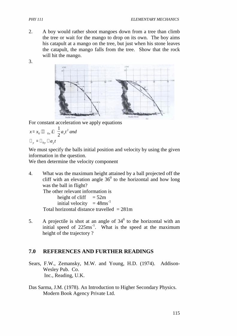
PHY 111 ELEMENTARY MECHANICS
115
2. A boy would rather shoot mangoes down from a tree than climb the tree or wait for the mango to drop on its own. The boy aims his catapult at a mango on the tree, but just when his stone leaves the catapult, the mango falls from the tree. Show that the rock will hit the mango.
3.
For constant acceleration we apply equations
x x t a t and
a t
x x
y y y
= + ∨ +
∨ = ∨ +
0 02
0
1
2
We must specify the balls initial position and velocity by using the given information in the question. We then determine the velocity component 4. What was the maximum height attained by a ball projected off the
cliff with an elevation angle 360 to the horizontal and how long was the ball in flight?
The other relevant information is height of cliff = 52m initial velocity = 48ms-1
Total horizontal distance travelled = 281m
5. A projectile is shot at an angle of 340 to the horizontal with an initial speed of 225ms-1. What is the speed at the maximum height of the trajectory ?
7.0 REFERENCES AND FURTHER READINGS Sears, F.W., Zemansky, M.W. and Young, H.D. (1974). Addison-
Wesley Pub. Co. Inc., Reading, U.K. Das Sarma, J.M. (1978). An Introduction to Higher Secondary Physics.
Modern Book Agency Private Ltd.
PHY 111 ELEMENTARY MECHANICS
116
Fishbane, P. M; Gasiorowicz, S. and Thranton, S.T., (1996). Physics for Scientists and Engineers. 2nd Edition Vol.1 prentice Hall, New Jersey.
UNIT 4 IMPULSE AND LINEAR MOMENTUM CONTENTS 1.0 Introduction 2.0 Objectives 3.0 Main Body
3.1 Definition of Impulse and Momentum 3.2 Motion of Rocket 3.3 Momentum
4.0 Conclusion 5.0 Summary 6.0 Tutor Marked Assignment (TMAs) 7.0 References and Further Reading 1.0 INTRODUCTION In Unit 7 we dealt with Force and Newton’s laws of motion. In this Unit we shall treat impulse and momentum as a consequence of the action of force. Pulse is a force acting for a very small or short duration of time as in a sudden impact of an object on another like in the impact of batting a tennis ball or an upsurge of current etc. Momentum of an object plays an important role in Newton’s second law. A force produces a change in momentum. When a system of particles is isolated, the total momentum is constant. This principle, known as the principle of conservation of momentum is particularly useful for understanding the behaviour of colliding objects. We shall learn about this principle in this unit of the cours. But first of all, we shall introduce the concept of impulse and momentum and how they are applied in motion of rockets.
PHY 111 ELEMENTARY MECHANICS
117
2.0 OBJECTIVES By the end of this unit, you should be able to; • define impulse and linear momentum. • write the mathematical definition of impulse and linear
momentum • solve problems in linear momentum • describe the motion of rockets using the linear momentum
principle • state the conditions for the conservation of linear momentum • apply the principles of conservation of linear momentum 3.0 MAIN BODY 3.1 Definition of Impulse and Momentum Imagine that a particle of mass m is moving along a straight line, Let us assume that the force acting on the particle is constant and directed along the line of motion of the particle. If the particle’s velocity at some initial time t = 0 is V0, then its velocity at a later time, t, is given by V = V0 + at I know you recognise this expression as one of the equations of motion we treated in units 5 and 6. Here, the constant of acceleration, a, is given by F/m from Newton’s second law. Making the substitution for a we get.
Ft mv mv= − 0 31.
you will notice that the left hand side of equation 3.1 is the product of the force and the time during which the force acts. This expression, (Ft) is called the impulse of the force. Generally, if a constant force, F acts for a short interval t1 to time t2 , the impulse of the force is defined mathematically as Impulse = F (t2- t1) = f�t
where ∆ t t t= −2 1 is very small interval. We notice that in Eqn.(3.1) the
right hand side of it contains the product of mass and velocity of the particle at two different times. The product, mv has a special name called momentum. This is very easy to remember. The experience you
PHY 111 ELEMENTARY MECHANICS
118
get when someone suddenly bumps into you unsuspectingly at a bend in the street is an impact of momentum. Momentum during a linear motion is also called linear momentum. We often use the symbol P to represent momentum. Momentum = P = mv So, for the time intervals t1 and t2 with corresponding particle velocities of V1 and V2, the impulse is given by,
F t t mv mv( )2 1 2 1− = − 3.2
We note that this relation between impulse and force is the same as that between work and kinetic energy change which we shall discuss later. The differences between them I would like you to also note are that: (i) impulse is a product of force and time but work is a product of
force and distance and depends on the angle between force and the displacement.
(ii) force and velocity are vector quantities and , impulse and
momentum are vector quantities but work and energy are scalars. In linear motion the force and velocity may be resolved, as we found earlier in this course, into their components along the x-axis and could have either positive or negative values.
Self Assessment Exercise 3.1 A particle of mass 2kg moves along the x-axis with an initial velocity of 3 ms-1. A force F = - 6N (i.e. the force is moving in the negative x-direction) is applied for a period of 3s. Find the initial velocity. Solution We apply the following eqn, F t t m m
thus
N s kg kg ms
or ms
( )
( ) ( ) ( ) ( ) ( )
2 1 2 1
21
21
6 3 2 2 3
6
− = ∨ − ∨
− = ∨ −
∨ = −
−
−
The final velocity of the particle is in the negative x - direction that is why we have a negative sign in the value for velocity.
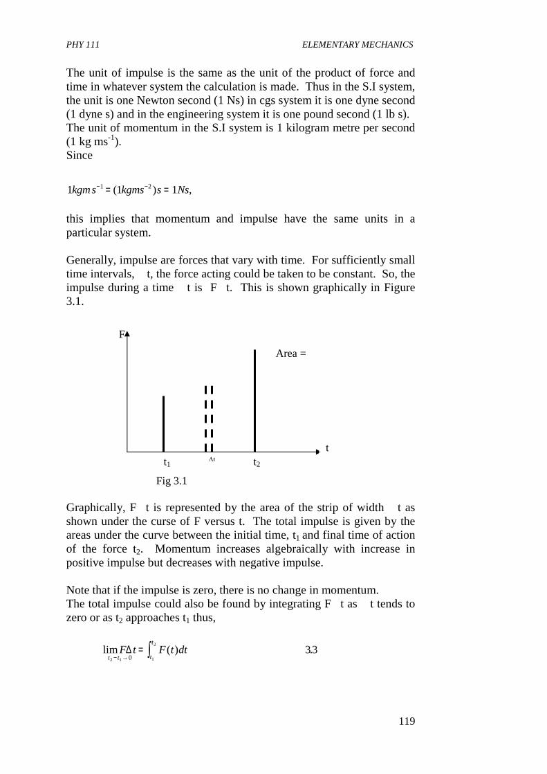
PHY 111 ELEMENTARY MECHANICS
119
The unit of impulse is the same as the unit of the product of force and time in whatever system the calculation is made. Thus in the S.I system, the unit is one Newton second (1 Ns) in cgs system it is one dyne second (1 dyne s) and in the engineering system it is one pound second (1 lb s). The unit of momentum in the S.I system is 1 kilogram metre per second (1 kg ms-1). Since
1 1 11 2kgms kgms s Ns− −= =( ) , this implies that momentum and impulse have the same units in a particular system. Generally, impulse are forces that vary with time. For sufficiently small time intervals, �t, the force acting could be taken to be constant. So, the impulse during a time �t is F�t. This is shown graphically in Figure 3.1. Graphically, F�t is represented by the area of the strip of width �t as shown under the curse of F versus t. The total impulse is given by the areas under the curve between the initial time, t1 and final time of action of the force t2. Momentum increases algebraically with increase in positive impulse but decreases with negative impulse. Note that if the impulse is zero, there is no change in momentum. The total impulse could also be found by integrating F�t as �t tends to zero or as t2 approaches t1 thus,
lim ( ) .F t F t dtt t t
t∆
2 1 1
2
033
− →= ∫
Area =
F
t t2 ∆t t1
Fig 3.1
t
PHY 111 ELEMENTARY MECHANICS
120
This value also gives the change in linear momentum of an object in which such a force acts.
dp
dtdt p t p t p
t
t= − =∫ ( ) ( ) .2 1 34
1
2
∆
We have now seen that impulse of a force is change in linear momentum. If a force acts during a time interval �t but is variable, then to calculate impulse we would need to know the function F (t) explicitly. However, this is usually not known. A way out is to define the average
for F by the equation
Ft
F t dtavet
t= ∫
135
1
2
∆( ) .
where �t = t2- t1 so from Eqns. 3.4 and 3.5 we get Total Impulse = Fave �t = �p 3.6 There are many examples which illustrate the relationship between the average force, its duration and change of linear momentum. A tennis player hits the ball while serving with a great force to impart linear momentum to the ball. To impart maximum possible momentum, the player follows through with the serve. This action prolongs the time of contact between the ball and the racket. Therefore to bring about the maximum possible change in the linear momentum, we should apply a large force as possible over a long time interval as possible. You may now like to apply these ideas to solve a problem Self Assessment Exercise 3.2
(1) A ball of mass 0.25kg moving horizontally with a velocity 20ms-1
is struck by a bat. The duration of contact is 10-2 s. After leaving the bat, the speed of the ball is 40 ms-1 in a direction opposite to its original direction of motion. Calculate the average force exerted by the bat.
(2) Give an example in which a weak force acts for a long time to
generate a substantial impulse Solution: Let J = impulse (i) Impulse , J = �p
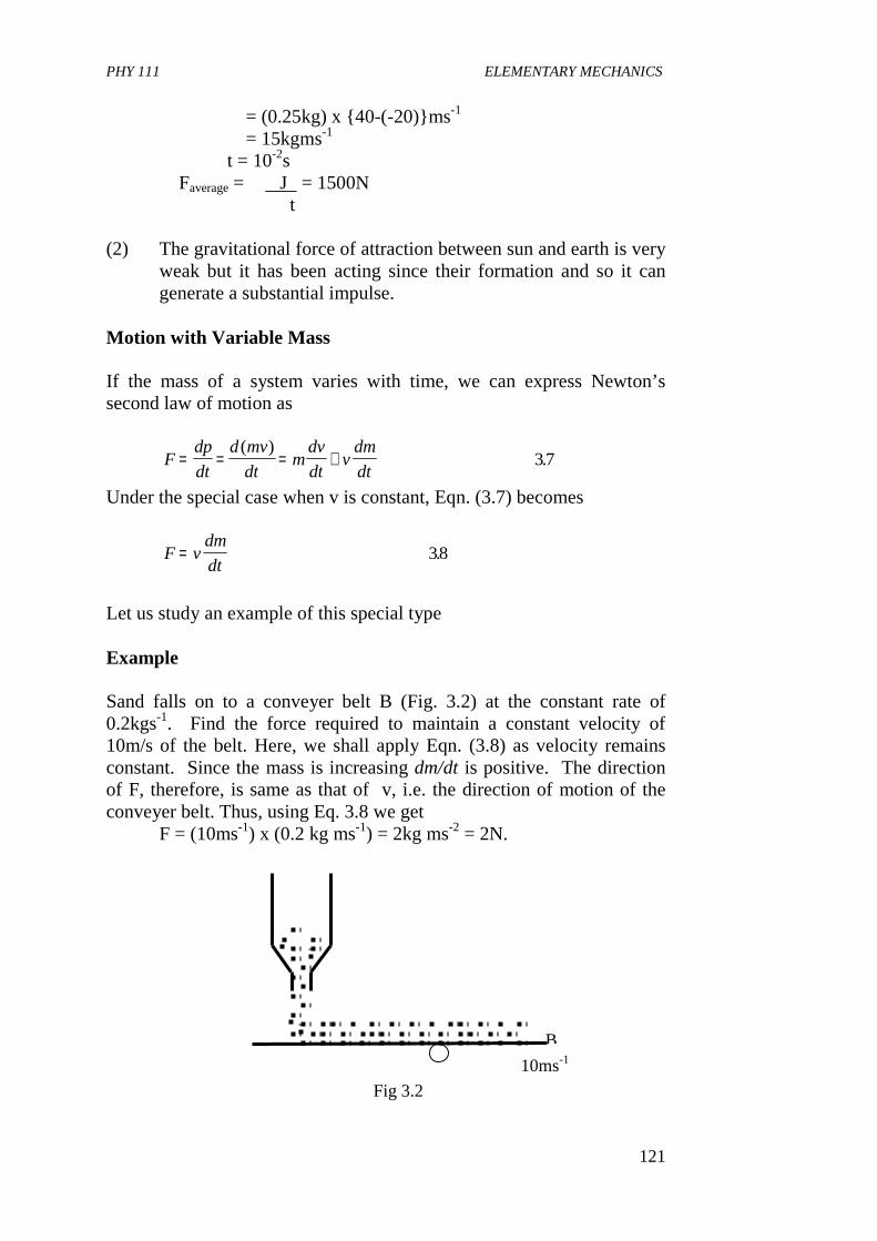
PHY 111 ELEMENTARY MECHANICS
121
= (0.25kg) x {40-(-20)}ms-1 = 15kgms-1 �t = 10-2s � Faverage = J = 1500N �t (2) The gravitational force of attraction between sun and earth is very
weak but it has been acting since their formation and so it can generate a substantial impulse.
Motion with Variable Mass If the mass of a system varies with time, we can express Newton’s second law of motion as
Fdp
dt
d mv
dtm
dv
dtv
dm
dt= = = +
( ).37
Under the special case when v is constant, Eqn. (3.7) becomes
F vdm
dt= 38.
Let us study an example of this special type Example Sand falls on to a conveyer belt B (Fig. 3.2) at the constant rate of 0.2kgs-1. Find the force required to maintain a constant velocity of 10m/s of the belt. Here, we shall apply Eqn. (3.8) as velocity remains constant. Since the mass is increasing dm/dt is positive. The direction of F, therefore, is same as that of v, i.e. the direction of motion of the conveyer belt. Thus, using Eq. 3.8 we get F = (10ms-1) x (0.2 kg ms-1) = 2kg ms-2 = 2N.
10ms-1
B
Fig 3.2
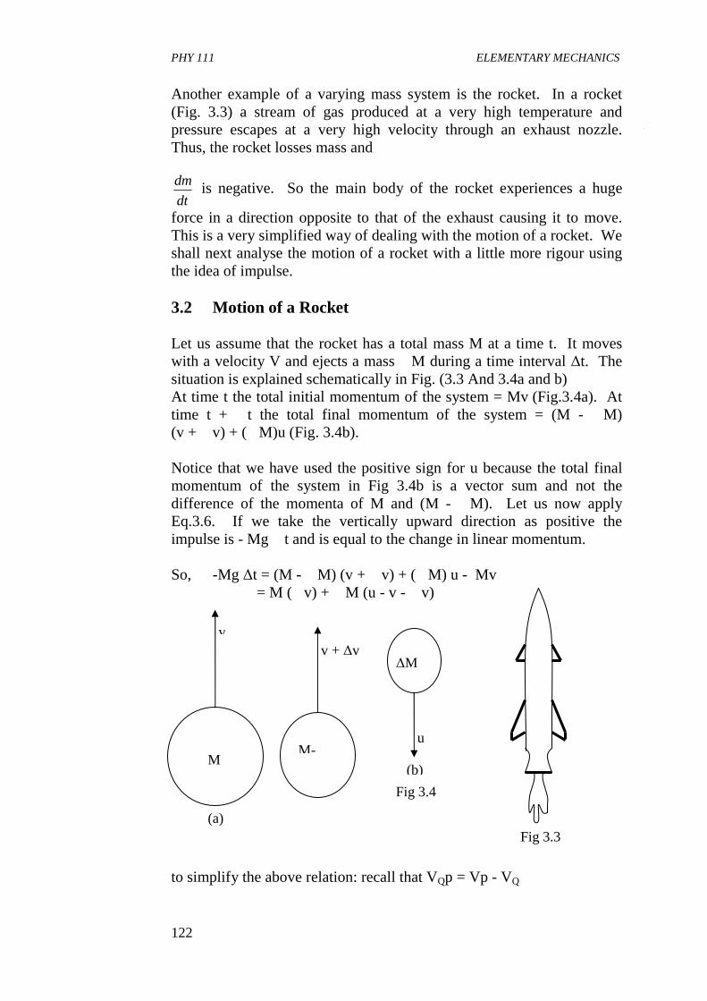
PHY 111 ELEMENTARY MECHANICS
122
Another example of a varying mass system is the rocket. In a rocket (Fig. 3.3) a stream of gas produced at a very high temperature and pressure escapes at a very high velocity through an exhaust nozzle. Thus, the rocket losses mass and
dm
dt is negative. So the main body of the rocket experiences a huge
force in a direction opposite to that of the exhaust causing it to move. This is a very simplified way of dealing with the motion of a rocket. We shall next analyse the motion of a rocket with a little more rigour using the idea of impulse. 3.2 Motion of a Rocket Let us assume that the rocket has a total mass M at a time t. It moves with a velocity V and ejects a mass �M during a time interval ∆t. The situation is explained schematically in Fig. (3.3 And 3.4a and b) At time t the total initial momentum of the system = Mv (Fig.3.4a). At time t + �t the total final momentum of the system = (M - �M) (v + �v) + (�M)u (Fig. 3.4b). Notice that we have used the positive sign for u because the total final momentum of the system in Fig 3.4b is a vector sum and not the difference of the momenta of M and (M - �M). Let us now apply Eq.3.6. If we take the vertically upward direction as positive the impulse is - Mg �t and is equal to the change in linear momentum. So, -Mg ∆t = (M - �M) (v + �v) + (�M) u - Mv = M (�v) + �M (u - v - �v) to simplify the above relation: recall that VQp = Vp - VQ
(b)
u
∆M
Fig 3.4
v + ∆v
M-
(a)
v
M
Fig 3.3
PHY 111 ELEMENTARY MECHANICS
123
∴ − = +gv
t M
M
turel
∆∆
∆∆
∆1
where u = u - (v + v)rel is the relative velocity
of the exhaust with respect to the rocket. Now, in the limit ∆ t → 0, we have
− = −gdv
dt M
dM
dturel
139.
The negative sign on the right-hand side of Eqn. 3.9 appears as
∆∆∆
tM
t
dM
dt→ = −0lim
, because M decreases with t.
so, when we apply Eq. 3.9 in numerical problems we just replace dM
dt by its magnitude. On integrating Eq. 3.9 with respect to t, we get
dv
dtdt gt u
dM
MrelM
M
= − + ∫∫00
1
where M0 is the initial mass of the rocket and M is its mass at time t. Now, if v0 is the initial velocity, then we get
v v u InM
Mgtrel− = −0
0
310.
We shall illustrate Eq. 3.10 with the help of an example. Example The stages of a two-stage rocket separately have masses 100kg and 10kg and contain 800 kg and 90 kg of fuel, respectively. What is the final velocity that can be achieved with exhaust velocity of 1.5 kms-1 relative to the rocket ? (Neglect any effect of gravity). Since we are neglecting gravity Eq. 3.10 reduces to
v v u InM
Mrel− =00
311.
Now, let the unit vector along the vertically upward direction be $n . So, Eq. 3.11 can be written as
v n v n u n InM
Mwhere u u nrel rel rel$ $ ( $) , $,− = − = −0
0
as the relative velocity of
the exhaust points vertically downward.
PHY 111 ELEMENTARY MECHANICS
124
v v u InM
Marel− =0
0
311.
For our problem, urel = 1.5 kms-1 For the first stage, v0 = 0 M0 = (800 + 90 + 100 + 10) kg = 1000kg M = (90 + 10 + 100)kg = 200kg, as the 800 kg fuel gets burnt in the first stage. Hence, from Eq.3.11 a, we get
v kms n
kms n n
x kms
kms
= −
= − −
=
=
−
−
−
−
( . )
( . ) ( )
. .
.
15 1200
1000
15 1 2 1 10
15 16
2 4
1
1
1
1
Note that the above will be the initial velocity for the second stage. Also note that at the beginning of the second stage there occurs another drop in mass to the extent of the mass of the first stage (i.e. 100kg). For the second stage, ∨ =
= + = =
∨ = −
= + = =
−
−
− − −
01
0
1
1 1 1
2 4
90 10 100 10
2 4 15110
1002 4 15 2 3 585 58
.
( ) ,
( . . )
( . . . ) . .
kms
M kg kg M kg
n kms
x kms kms kms
The final result of this Example has to be rounded off to two significant digits. Here we have a special case as the digit to be discarded is 5. By convention , we have rounded off to the nearest even number. Let us now follow up this example with an exercise Self Assessment Exercise 3.3
PHY 111 ELEMENTARY MECHANICS
125
Find the final velocity of the rocket in the Example above taking it to be single-stage, i.e. its mass is 100kg and it carries 890kg of fuel. Hence comment whether the two-stage rocket has an advantage over single stage or not. Solution Had it been a single stage rocket, then v0 = 0 M0 = (890 + 100)kg = 990kg M = 100kg V = (- 1.5km s-1)[ln 100 ] 990 = (- 1.5km s-1)(In 10- In99) =3.4kms1 which is 41% less than the value of velocity (5.8kms-1) attained in a double-stage rocket. Hence double-stage has an advantage over the single-stage. 3.3 Linear Momentum Let us first study a system of two interacting particles’1' and ‘2' having masses m1 and m2 (Fig.3.5). Let p1 and p2 be their linear momenta. The total linear momentum p of this system is simply the vector sum of the linear momenta of theses two particles.
p = p1 + p2 3.12 From Newton’s second law, the rate to change of p1 is the vector sum of all the forces acting on 1, i.e. the total external force Fel on it and the internal force f21 due to 2:
F fdp
dtael + =21
1 313.
Similarly, for particle 2:
F fdp
dtbel + =21
2 313.
2
Fe2
f12
Fe1
f21
1
Fig 3.5
PHY 111 ELEMENTARY MECHANICS
126
From Newton’s third law, we know that f12 = -f21. Therefore, on adding Equation .3.13 a and 3.13b, we get
F Fedp
dt
dp
dte1 21 2+ = + , which may be written as
Fd
dtp pe = +( ),1 2
where Fe is the net external force on the system.
Therefore, from Eq. 3.12
Fdp
dte = . .314
Thus, in a system of interacting particles, it is the net external force which produces acceleration and not the internal forces. Now, we shall see how Equation. 3.14 leads to the principle of conservation of linear momentum. 3.4 Conservation of Linear Momentum In the special case when the net external force Fe is zero, Equation 3.14 gives
dp
dt= 0 315, .
so that p = p1 + p2 = a constant vector. This is the principle of conservation of linear momentum for a two-particle system. It is equally valid for a system of any number of particles. Its formal proof for a many-particle system will be given later. It states that:
“if the net external force acting on a system is zero, then its total linear momentum is conserved”.
Let us now apply this principle. Example A vessel at rest explodes, breaking into three pieces. Two pieces having equal mass fly off perpendicular to one another with the some speed of 30 ms-1. Show that immediately after the explosion the third piece moves in the plane of the other two pieces. If the third piece has three times the mass of either of the other piece, what is the magnitude of its velocity immediately after the explosion?
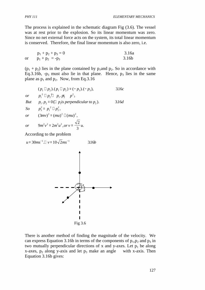
PHY 111 ELEMENTARY MECHANICS
127
The process is explained in the schematic diagram Fig (3.6). The vessel was at rest prior to the explosion. So its linear momentum was zero. Since no net external force acts on the system, its total linear momentum is conserved. Therefore, the final linear momentum is also zero, i.e. p1 + p2 + p3 = 0 3.16a or p1 + p2 = -p3 3.16b
(p1 + p2) lies in the plane contained by p1and p2. So in accordance with Eq.3.16b, -p3 must also lie in that plane. Hence, p3 lies in the same plane as p1 and p2. Now, from Eq.3.16
( ).( ) ( ).( ), .
.
. ( ). .
,
( ) ( ) ( ) ,
, .
p p p p p p c
or p p p p p
But p p p is perpendicular to p d
So p p p
or mv mu mu
or m v m u or v u
1 2 1 2 3 3
12
22
1 22
3
1 2 1 2
32
12
22
2 2 2
2 2 2 2
316
0 316
3
9 22
3
+ + = − −
+ + == ∴
= +
= +
= =
According to the problem u ms v ms b= ∴ =− −30 10 2 3161 1. .
There is another method of finding the magnitude of the velocity. We can express Equation 3.16b in terms of the components of p1,p2 and p3 in two mutually perpendicular directions of x and y-axes. Let p1 be along x-axes, p2 along y-axis and let p3 make an angle � with x-axis. Then Equation 3.16b gives:
Fig 3.6
PHY 111 ELEMENTARY MECHANICS
128
p i p j p i p j1 2 3 3 317$ $ ( cos $ sin ). .+ = − +∧
θ θ
This equation is satisfied iff (see Eq. 1.6) − = − =
= +
p p p p
or p p p
3 1 3 2
32
12
22
318cos , sin .
,
θ θWhich is Eqn. 3.16c
Self Assessment Exercise 3.4 Find the direction of v in the example above. From the above example and the way we obtained the principle of conservation of momentum, it may appear that the principle is limited in its application. This is because we have assumed that no net external force acts on the system of particles. However, the scope of the principle is much broader. There are many cases in which an external force, such as gravity, is very weak compared to the internal forces. The explosion of a rocket in mid air is an example. Since the explosion lasts for a very brief time, the external force can be neglected in this case. In examples of this type, linear momentum is conserved to a very good approximation. Again, if a force is applied to a system by an external agent, then the system exerts an equal and opposite force on the agent. Now if we consider the agent and the system to be a part of a new, larger system, then the momentum of this new system is conserved. Since there is no larger system containing the universe, its total linear momentum is conserved. We have seen that whenever we have a system of particles on which no net external force acts, we can apply the law of conservation of linear momentum to analyse their motion. In fact, the advantage is that this law enables us to describe their motion without knowing the details of the forces involved. 4.0 CONCLUSION In this unit, you have learnt • that impulse is a force of very short duration • that linear momentum is given by the product of the force and
velocity.
PHY 111 ELEMENTARY MECHANICS
129
• that force is as a result of change of momentum of a particle • that the principle of momentum change is applied in rocket
propulsion • that when two objects collide, their momentum must be
conserved. 5.0 SUMMARY What you have learnt in this unit are: • that impulse = F�t where �t = t2 - t1 is a very short time interval
F, t2 and t1 have their usual meanings. • that momentum, p = mv where m = mass of particle and v =
velocity of particle • that force = mv2 - mv1 = �mv = p or force
= = = +dp
dt
d mv
dtm
dv
dtv
dm
dt
( )
• that the sum of the linear momentum p for a system of two particle p having mass m1 and m2 and linear momenta p1 and p2 is p = p1 + p2
• that linear momentum is always conserved ie if dp
dt= 0 , then
momentum is conserved. Note If the external force acting on a system is zero, then its total linear momentum is conserved. 6.0 TUTOR MARKED ASSIGNMENTS (TMA) (1) A ball of mass 0.4 kg is thrown against a brick wall. When it
strikes the wall it is moving horizontally to the left at 3 ms-1, and it rebounds horizontally to the right at 20m s-1. Find the impulse of the force exerted on the ball by the wall.
(2) A ball moves with a velocity of 1.2m/s in the positive y-direction on a table and strikes an identical ball that was at rest. The rolling ball is deflected so that its velocity has a component of 0.80 ms-1
in the +ve y- direction and a component of 0.56m s-1 in the + x-direction. What are the final velocity and final speed of the struck ball?
7.0 REFERENCES AND FURTHER READING
PHY 111 ELEMENTARY MECHANICS
130
Sears, F.W., Zemansky M.W and Young H.D (1975) College Physics (4th Ed) Addison - Wesley Publ Co, Reading U.K.
Indira Gandi National Open University School of Sciences. PHE- 01,
Elementary Mechanics, Concepts in Mechanics 1 Fishbane, P.M Gasiorowicz, S and Thronton S.T(199), Physic for
Scientists and Engineers, (2* Edition) Prentices Hall Publ., New Jersey.
Nelkon M and Parker P (1970) Advanced Level Physics, Heinemann
Educational Books Ltd London. UNIT 5 LINEAR COLLISIONS CONTENTS 1.0 Introduction 2.0 Objectives 3.0 Main Body
3.1 Classification of Collisions 3.2 Perfectly Inelastic Collisions
3.2.1 Energy Lost in Perfectly Inelastic Collisions 3.2.2 Explosions
3.3 Elastic and Inelastic Collisions 4.0 Conclusion 5.0 Summary 6.0 Tutor Marked Assignments (TMAs) 7.0 References and Further Reading 1.0 INTRODUCTION Attempts to understand collisions were carried out by Galileo and his contemporaries. The laws that describe collisions in one dimension were formulated by John Wallis, Christopher Wren and Christian Huygens is 1668. In this Unit you will learn about collisions between two objects moving along a straight line. You will find out what happens when objects collide. The interesting phenomena of their change in velocity, momentum and possibly change in kinetic energy will be discussed. This will lead us to the understanding of the phenomenon of explosions that is popularly applied in war fares. Relax and find out as you read how simple observations lead to important scientific discoveries. 2.0 OBJECTIVES By the end of this Unit, you should be able to:
PHY 111 ELEMENTARY MECHANICS
131
(i) define collision (ii) classify collisions (iii) apply the principles of conservation of energy and momentum in
order to determine the energy lost by colliding particles. (iv) use collision principle in explaining rocket propulsion (v) explain what is meant by elastic, inelastic and perfectly inelastic
collisions (vi) solve problems in collisions. 3.0 MAIN BODY 3.1 Classification of Collisions In Unit 9 you learnt about impulse and momentum. You learnt that impulse is a force which acts for only a very short duration of time. This means that impulsive forces are the types of forces we experience during collisions. Have you ever collided with somebody or with some object unsuspectingly? Can you recall some actions that depict collisions? An example is the collision of two balls rolling on a table. Another is the popular pin-pong game popularly called table tennis. You can imagine the very short time of impact between the tennis ball and the bat used by the player. Collision is the sudden impact felt between two objects. You may ask what happens during collisions? During collision there could be transfer of energy from one object to the other or energy could be transformed from one form to another. For example, some of the kinetic energy of the tennis ball is converted to sound energy on hitting the bat of the player while playing table tennis. Also during explosions, potential energy is converted to kinetic energy and sound energy. From the principle of conservation of momentum you studied in unit 9, you learnt that momentum of colliding particles must be equal before and after collision. This knowledge will be applied in this unit to determine the velocity of objects after collisions. There are two types of collisions viz elastic and inelastic collisions. Elastic collision is a collision between two or more objects during which no energy is lost. That is, the total kinetic energy of the objects before collision is equal to the total kinetic energy of the objects after collision. In other words, kinetic energy is conserved. But if the kinetic energy is not conserved in a collision the collision is called inelastic collision. This implies that during inelastic collision, some of the kinetic energy is
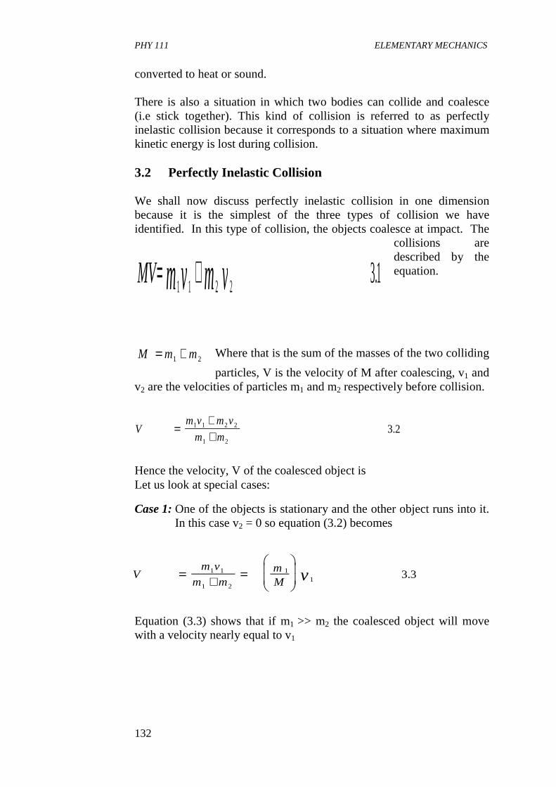
PHY 111 ELEMENTARY MECHANICS
132
converted to heat or sound. There is also a situation in which two bodies can collide and coalesce (i.e stick together). This kind of collision is referred to as perfectly inelastic collision because it corresponds to a situation where maximum kinetic energy is lost during collision. 3.2 Perfectly Inelastic Collision We shall now discuss perfectly inelastic collision in one dimension because it is the simplest of the three types of collision we have identified. In this type of collision, the objects coalesce at impact. The
collisions are described by the equation.
Where that is the sum of the masses of the two colliding
particles, V is the velocity of M after coalescing, v1 and v2 are the velocities of particles m1 and m2 respectively before collision.
Hence the velocity, V of the coalesced object is Let us look at special cases:
Case 1: One of the objects is stationary and the other object runs into it. In this case v2 = 0 so equation (3.2) becomes
Equation (3.3) shows that if m1 >> m2 the coalesced object will move with a velocity nearly equal to v1
MV m v m v= +1 1 2 2 3 1.
M m m= +1 2
Vm v m v
m m=
++
1 1 2 2
1 2
3 2.
Vm v
m mmM v=
+=
1 1
1 2
11 3 3.
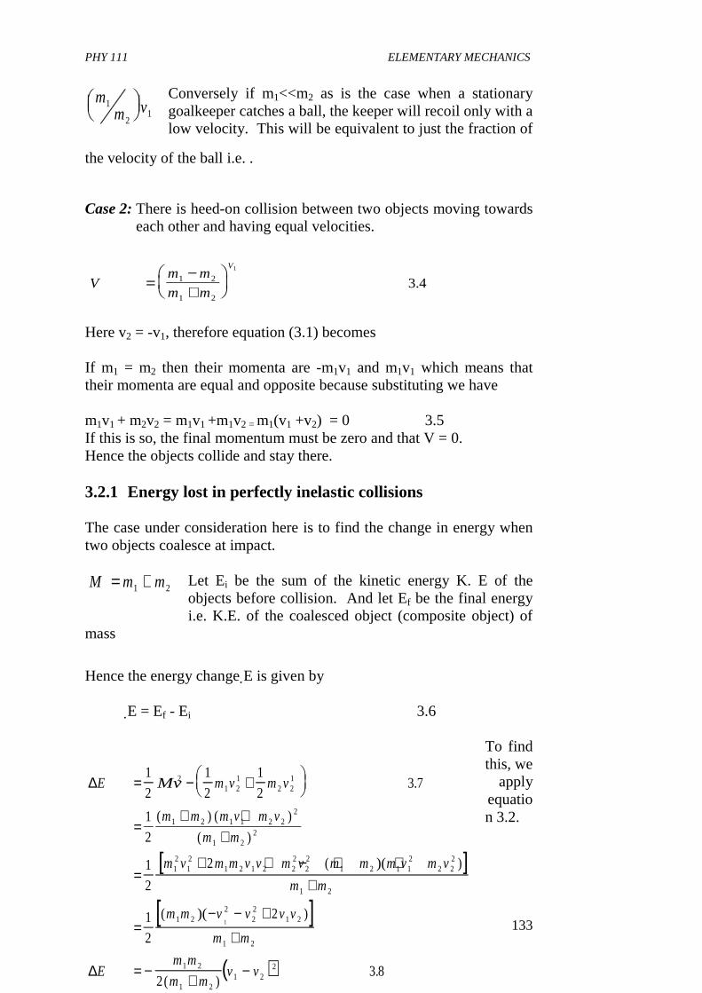
PHY 111 ELEMENTARY MECHANICS
133
Conversely if m1<<m2 as is the case when a stationary goalkeeper catches a ball, the keeper will recoil only with a low velocity. This will be equivalent to just the fraction of
the velocity of the ball i.e. .
Case 2: There is heed-on collision between two objects moving towards
each other and having equal velocities.
Here v2 = -v1, therefore equation (3.1) becomes If m1 = m2 then their momenta are -m1v1 and m1v1 which means that their momenta are equal and opposite because substituting we have m1v1 + m2v2 = m1v1 +m1v2 = m1(v1 +v2) = 0 3.5 If this is so, the final momentum must be zero and that V = 0. Hence the objects collide and stay there. 3.2.1 Energy lost in perfectly inelastic collisions The case under consideration here is to find the change in energy when two objects coalesce at impact.
Let Ei be the sum of the kinetic energy K. E of the objects before collision. And let Ef be the final energy i.e. K.E. of the coalesced object (composite object) of
mass
Hence the energy change E is given by
E = Ef - Ei 3.6
To find this, we
apply equation 3.2.
mm
1
2
mm v1
21
Vm m
m m
V
=−+
1 2
1 2
1
3 4.
M m m= +1 2
[ ]
[ ]
∆
∆
E Mv m v m v
m m m v m v
m m
m v m m v v m v m m m v m v
m m
m m v v v v
m m
Em m
m
= − +
=+ +
+
=+ + − + +
+
=− − +
+
= −
1
2
1
2
1
23 7
1
2
1
2
2
1
2
2
2
21 2
12 2
1
1 2 1 1 2 22
1 22
12
12
1 2 1 2 22
22
1 2 1 12
2 22
1 2
1 22
22
1 2
1 2
1 2
1
.
( ) ( )
( )
( )( )
( )( )
(( )
1 21 2
2 3 8+
−m
v v)
.
PHY 111 ELEMENTARY MECHANICS
134
Since kinetic Energy is ½mv2, we have Note that the expression in the right hand side of equation (3.8) is always negative. This is because energy is lost in such a collision. This means that the collision is inelastic. This composite object is at rest in only one frame of reference. In this frame there is no final kinetic energy so the collision is known as perfectly inelastic collision. In this frame of reference, the total momentum is zero. The total kinetic energy of the system before collision goes into the coalesion of the objects. Self Assessment Exercise 3.1 A dog running at a speed of 32km h-1 jumps into a stationary canoe on the river Niger at Lokoja. The dog’s mass is 14kg and that of the canoe plus the rower is 160kg. Let us assume that the water surface is frictionless, (i) what is the speed of the canoe after the collision. (ii) what is the ratio of the energy loss to the initial energy (iii) where did the energy go? Solution: The initial momentum is the momentum of the dog only. This is because the canoe is at rest. Given mass of dog as m and initial velocity of the dog (i.e. its velocity as it enters the canoe) as vo then Initial momentum Pi = mvo the final momentum Pf = Mv where v is the unknown speed, and M is the sum of the masses of the canoe, rower and dog = 174kg. Since (i) Initial Momentum = final momentum, therefore
PHY 111 ELEMENTARY MECHANICS
135
(ii) The initial energy is the K.E. of the dog, therefore
(iii) The final energy is all in form of K.E. Therefore
Hence, the loss in energy is
The ratio of the energy loss to the initial energy is given by
This means that E/Ki is of value less than unity. The energy has decreased in value. Substituting our values for m and M we get
vP
M
P
Mmv
M
kg kmh
kg
kmh
or v ms
f i
o
= =
= =
=
=
−
−
−
( )( )
.
.
14 32
174
2 6
0 72
1
1
1
K mvi =1
2 02
K mv
Mmv
M
m
Mmv
m
MK
f
f
i
K
=
=
=
=
1
2
1
2
1
2
2
02
02
∆E K K Km
MK
Km
M
i f i i
i
= − = −
= −
1
∆E
K
m
Mi
= −1
∆E
k
kg
kgi
= −
=
114
174
0 92.
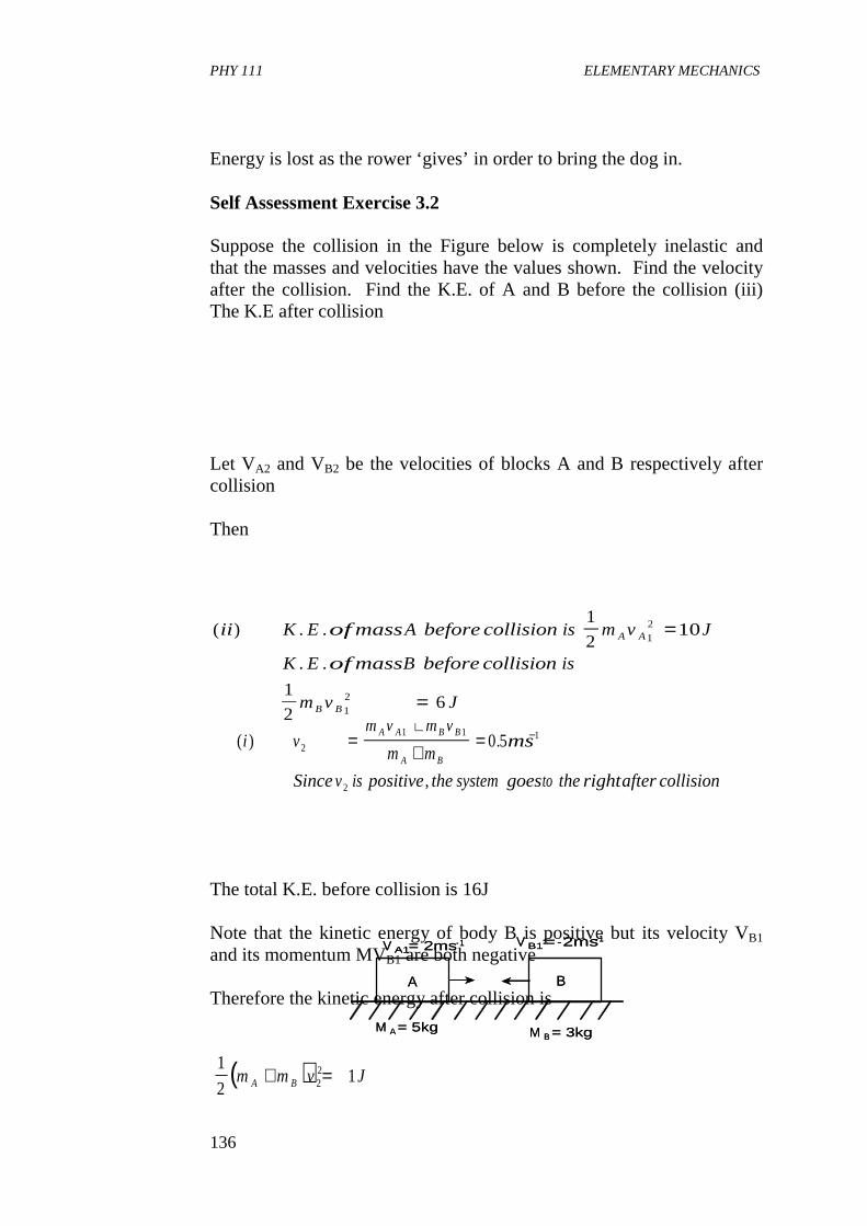
PHY 111 ELEMENTARY MECHANICS
136
A
M A= 5kg
V A1= 2ms-1 V B1= -2ms-1
B
M B = 3kg
A
M A= 5kg
V A1= 2ms-1 V B1= -2ms-1
B
M B = 3kg
Energy is lost as the rower ‘gives’ in order to bring the dog in. Self Assessment Exercise 3.2 Suppose the collision in the Figure below is completely inelastic and that the masses and velocities have the values shown. Find the velocity after the collision. Find the K.E. of A and B before the collision (iii) The K.E after collision Let VA2 and VB2 be the velocities of blocks A and B respectively after collision Then
The total K.E. before collision is 16J Note that the kinetic energy of body B is positive but its velocity VB1 and its momentum MVB1 are both negative Therefore the kinetic energy after collision is
( ) .
,
i vm v m v
m mms
Sincev is positive thesystemgoesto therightaftercollision
A A B B
A B2
1 1 1
2
0 5=++
= −
( ) . .
. .
ii K E ofmassA beforecollision is m v J
K E ofmassB beforecollision is
m v J
A A
B B
1
210
1
26
12
12
=
=
( )1
212
2m m v JA B+ =
PHY 111 ELEMENTARY MECHANICS
137
What has happened to the rest of the K.E. they had before collision? For the same conditions above when
The masses A and B travelling towards each other and under goes perfect elastic
collision (i) what are the velocities of masses A and B after collision (ii) the kinetic energy before collision (iii) the total K. E. after collision. Solution: From the principle of conservation of momentum,
Since the collision is perfectly elastic. VB2 - VA2 = - (VB1 - VA1)
= 4m s-1. Solving these equations simultaneously we obtain
This implies that both bodies reverse their directions of motion. A now travels to the left at 1ms-1 and B goes to the right at 3ms-1. (ii) The total K.E. after collision is
We see that this is equal to the total K.E. before collision which confirms that the collision is perfectly elastic. 3.2.2 Explosions Let us consider a case where two objects approach each other and merge in a frame of reference where the total momentum is zero. We also assume that these objects remain at rest after merging. When the opposite of this action occurs, that is, when an object at rest in such a frame of reference breaks up into two or more objects with an attendant
m kg m kg
v ms v ms
A B
A B
= =
= = −− −
5 3
2 211
11
,
,
( ) ( )( ) ( )( )
( ) ( )
i kg ms kg ms
kg v kg v
v v ms
A B
A B
5 2 3 2
5 3
5 3 4
1 1
2 2
2 21
− −
−
+ −= +
∴ + =
v ms v msA B21
211 3= − =− −;
( ) ( )1
25 1
1
23 1 161 2 1 2
( ) ( )kg ms kg ms J− + − =− −
PHY 111 ELEMENTARY MECHANICS
138
sound, it becomes an explosion. The initial object of mass at rest breaks up into two objects, and they move
with velocities such that the momentum is zero. That is their
3.9
From the law of energy conservation, once an object has initial potential energy U, then explosion is possible.
Explosives used during wars have potential energy stored in molecules. When the explosives are detonated, there is tremendous release of energy. Let us now use an example to explain this concept. Self Assessment Exercise 3.3 Let us consider what happens during fission of an element. That is, the case in which an unstable atomic nucleus disintegrates. Let’s use element Polonium, for example. It’s symbol is 210Pb which has mass 3.49 x 10⁻²⁵ kg. This element can decay into an alpha particle (actually a Helium nucleus) of mass 6.64 x 10⁻²⁷kg and a type of lead nucleus (symbol 206Pb) of mass 3.42 x 10⁻²⁵kg. That is
The products of the decay have K.E. of 8.65 x 10⁻¹³J above any K.E. possessed by the polonium nucleus itself. For the decay of such a polonium nucleus at rest, Find the speeds of the particle and the lead nucleus? Solution: Let Q = the K.E. of the products of decay Then by conservation of momentum law and
M m m= +1 2m andm1 2
m v m v1 1 2 2 0+ =
∴ = +U m v m v1
2
1
23101 1
22 2
2 .
210 206P PbO → ∝+
M v M vpb pb∝ ∝ =
PHY 111 ELEMENTARY MECHANICS
139
where v is the speed of the respective particles as indicated by the subscripts. We solve these two equations for the variables of interest and find that
Given that Q = 8.65 x 10¹³J, then computing the above gives v = 1.60 x 10⁷ms-1 and
vpb = 3.10 x 10⁵ ms-1
We observe that the speed of the heavier of the two products of decay is much less than that of the lighter one. This result is seen in the conservation of momentum equation. 3.3 Elastic and Inelastic Collisions In an elastic collision in one dimension, there is no transfer of mass from one object to another. This implies that the total kinetic energy of the objects before collision is equal to the total kinetic energy of the objects after collision. If the final velocities of the two objects 1 and 2 are v3 and v4 then additionally
By the conservation of energy, it follows that
We can find the final velocities of the colliding objects if we know the initial velocities. Rewriting equation (3.11) we have
Q m v M vpb pb= +∝ ∝
1
2
1
22 2
vQ
m m M
and
vQ
M M m
pb
pbpb pb
∝∝ ∝
∝
=+
=+
2
1
2
1
( / )
( / )
m v m v m v m v1 1 2 2 1 3 3 4 311+ − + .
1
2
1
2
1
2
1
23121 1
22 2
22 3
22 4
2m v m v m v m v+ = + .
m v v m v v1 1 3 2 2 3 313( ) ( ) .− = − −

PHY 111 ELEMENTARY MECHANICS
140
Now, applying our knowledge of mathematical algebra, we use.
We now divide both sides of equation (3.14) by the two sides of equation (3.13) to get
Let u be the relative velocity of the two colliding particles (objects) then,
We conclude from Eqn. (3.16) that in an elastic collision, the relative velocity of the colliding objects change sign but does not change in magnitude. As a rule of thumb always think of a perfectly elastic rubber ball hitting a brick well. Relative velocity behaves like the velocity of this rubber. We now solve Eqn.(3.15) for one of the unknown variables like v4 Thus
3.17
Substituting this in the momentum conservation equation (3.11) we get
v v v v v v
and
v v v v v v
to rewrite equation in the form
v v v v v v v vm
12
42
1 3 1 3
22
42
2 4 2 4
1 1 3 1 3 2 4 2 4
12
1
2
1
2314
− = − +
− = − +
− + = − − +
( )( )
( )( )
( )
( )( ) ( )( ) .
v v v v1 3 2 4 315+ = + .
u v v
and
u v v
subsituting thesein eqn weget
u u
i
f
i f
= −
= −
= −
1 2
3 4
315
316
. ( . )
.
v v v v4 1 2 3= − +
PHY 111 ELEMENTARY MECHANICS
141
V 2= 0
V 1 V 4M 1
(c)
V3 M 2M 1M2
V 2= 0
V 1 V 4M 1
(c)
V3 M 2M 1M2
As an exercise, show the derivation of equation (3.19).Equations (3.18)
and (3.19) seem complicated. Let us now simplify them by applying them to practical situations (3.19). 1. A Scenario where object 2 is initially at rest.
Here V2 = O so that equations (3.18) and (3.19) reduce to
1a. If the two objects have equal masses i.e.
Here. This means that the moving object after
collision stays at rest while the object formerly at rest now moves with the initial velocity of the first object. This effect can be seen vividly in hard billiard shots along a line.
m v m v m v m v v v
regrouping termsweget
m m v m m v m v
vm m
m m
m
m mv
Similarly wecan solvefor v to get
vm
m mv
m m
m mv
1 1 2 2 1 3 2 1 2 3
1 2 3 1 2 1 2 2
31 2
1 2
2
1 22
4
41
1 21
2 1
1 22
2
2318
2319
+ = + − +
+ = − +
=−+
+
+
=+
+
−+
( )
,
( ) ( ) ;
.
,
.
vm m
m m
and
vm
m mv
31 2
1 2
41
1 21
3 20
2
=−+
=+
.
m m1 2=
v and v v3 4 10= =
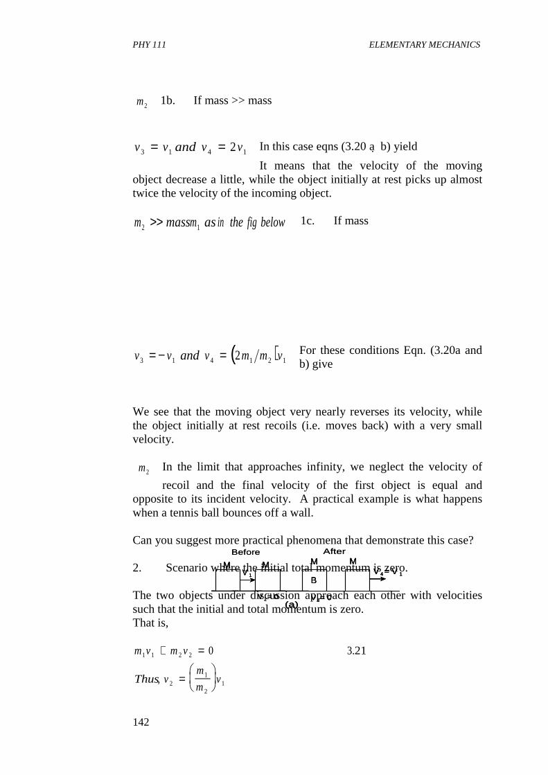
PHY 111 ELEMENTARY MECHANICS
142
AfterBefore
M
V 2= 0
V 1B
V 3= 0
M M MV 4 = V 1
(a)
AfterBefore
M
V 2= 0
V 1B
V 3= 0
M M MV 4 = V 1
(a)
M
V 2= 0
V 1B
V 3= 0
M M MV 4 = V 1
(a)
1b. If mass >> mass
In this case eqns (3.20 a b) yield
It means that the velocity of the moving object decrease a little, while the object initially at rest picks up almost twice the velocity of the incoming object.
1c. If mass
For these conditions Eqn. (3.20a and b) give
We see that the moving object very nearly reverses its velocity, while the object initially at rest recoils (i.e. moves back) with a very small velocity.
In the limit that approaches infinity, we neglect the velocity of
recoil and the final velocity of the first object is equal and opposite to its incident velocity. A practical example is what happens when a tennis ball bounces off a wall. Can you suggest more practical phenomena that demonstrate this case? 2. Scenario where the initial total momentum is zero. The two objects under discussion approach each other with velocities such that the initial and total momentum is zero. That is,
m2
v v and v v3 1 4 12= =
m massm asin the fig below2 1>>
( )v v and v m m v3 1 4 1 2 12= − =
m2
m v m v
Thusvm
mv
1 1 2 2
21
21
0 321+ =
=
.
,
PHY 111 ELEMENTARY MECHANICS
143
vm
mv
m
mv v4
1
23
1
21 2 3 23=
=
= − .
Putting this value for v2 in Eqn. (3.18) we find
To solve for, we apply the conditions set out in this
scenario that the initial total momentum was zero. Therefore, by the conservation of liner momentum,
the final total momentum must also be zero and
We conclude that for the case where total momentum is zero, the velocities of each of the objects are unchanged in magnitude but they change in sign. We conclude that in each of these cases each of the objects behave as if it hit an infinite massive brick wall. We now do some examples Self Assessment Exercise 3.4 A bullet is fired in the + x-direction into a stationary block of wood that has a mass of 5kg. The speed of the bullet before entry into the block is V0 = 500ms-1. What is the speed of the block just after the bullet has become embedded? What distance will the block slide on a surface with coefficient of friction equal to 0.50? Solution: Let m = mass of the bullet
V0 = bullet’s velocity before it enters the block of wood. M = combined mass of bullet and wood.
vm m
m mv
m
m m
m
mv
m m m
m mv
v
31 2
1 21
2
1 2
1
21
1 2 1
1 21
1
2
2
3 22
=−+
+
+
−
=− −
+
= − .
v4( )m v m v1 3 2 4+
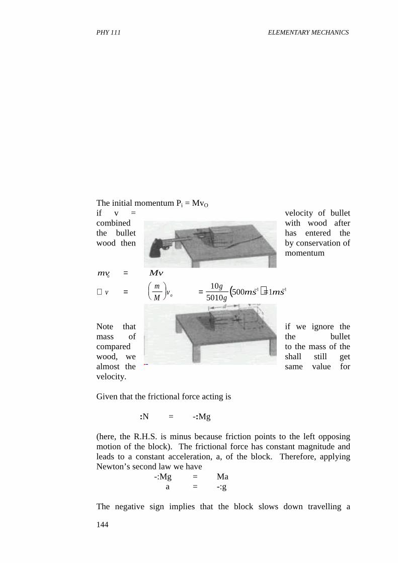
PHY 111 ELEMENTARY MECHANICS
144
The initial momentum Pi = MvO if v = velocity of bullet combined with wood after the bullet has entered the wood then by conservation of
momentum
Note that if we ignore the mass of the bullet compared to the mass of the wood, we shall still get almost the same value for velocity. Given that the frictional force acting is :N = -:Mg (here, the R.H.S. is minus because friction points to the left opposing motion of the block). The frictional force has constant magnitude and leads to a constant acceleration, a, of the block. Therefore, applying Newton’s second law we have -:Mg = Ma a = -:g The negative sign implies that the block slows down travelling a
( )mv Mv
vm
Mv
g
gms ms
o
o
=
∴ =
= =− −10
5010500 11 1
PHY 111 ELEMENTARY MECHANICS
145
distance d before it stops. Since acceleration is uniform, we use the relation
Now with vf = 0 (that’s when the block stops moving) we have
Self Assessment Exercise 3.5 An empty freight car of mass 10,000kg rolls at 2ms-1 along a level track and collides with a loaded car of mass 20,000kg, standing at rest with brakes released. If the cars couple together, 1. find their speed after the collision. 2. find the decrease in kenetic energy as a result of the collision 3. with what speed should the loaded car be rolling toward the empty
car in other that both shall be brought to rest by the collision? Solution: Recall that, (a) The momentum before collision = momentum after collision
i.e.
(b) Now, K.E. before
collision - K.E. after collision = loss K.E.
v v ad from the fact thatv v atf i o2 2 2− = − =( ).
dv
a
v
g
ms
ms
m
i i= = =
=
−
−
2 2 1 2
22
1
2
1
2
1
0 5 9 8
0 1
µ( )
( . )( . )
.
m v m v Mv
vm
Mv
kg
kgx ms
v ms
1 1 2 2
11
1
1
10000
300002
0 67
+ =
∴ =
=
=
−
−.
1
2
1
2
1
21
210 000 2
1
230 000 67
20000 6666 65 13 333
1 1 1 22
1
5000 2
1
15000 2
2m v m v mv
X
i e J
+ −
∴ −
− =
, , (. )
. . . , .
PHY 111 ELEMENTARY MECHANICS
146
(c) Answer is 1ms-1 4.0 CONCLUSION In this unit, you have learnt • that collision is the sudden impact felt between two objects
that there are two types of collisions viz: elastic and inelastic collisions
• how to determine the energy lost in perfectly inelastic collisions • how to distinguish between elastic and inelastic collisions • how to apply the principles of the conservation of energy and
momentum in the solution of collision problems. • how to apply the collision principle in the study of rocket
propulsion. 5.0 SUMMARY What you have learnt in this unit are • that collision is the sudden impact felt between two objects.
• that collisions can be classified into elastic collisions - inelastic collisions - erfectly inelastic collisions • that during elastic collision no energy is lost, that is,
- that the total K.E. of the colliding particles before and after collision are equal
• that during inelastic collision kinetic energy is not conserved. • that when bodies collide and coalesce, the phenomenon
constitutes perfectly inelastic collision. • that collisions are described by the equation
where the symbols have their usual meaning • that for perfectly inelastic collision when the objects coalesce on
impact that before collision one of the objects was at rest and the other runs into it, then,
that if the coalesced object will move with a velocity
nearly equal to v1
m v m v Mv1 1 2 2+ =
vm v
m mmM
v=+
=
1 1
1 2
11
m m1 2>> ,
PHY 111 ELEMENTARY MECHANICS
147
• that if then, will move with velocity
• that for head-on collision of two objects moving
towards each other with equal velocities
• that the energy change is given by
• that the negative sign in the R.H.S. of the equation above shows that energy is lost in such a collision.
• that the ratio of the energy loss to the initial energy is given by
• that E/Ki is of value less than unity. • that when a stationary object disintegrates with attendant sound,
it becomes, an explosion. Here, after explosion, particles move but their momentum is conserved, hence,
that for elastic collision
m m1 2<< ,m2
m
mv1
21
velocities v v
hence
vm m
m mv
,
,2 1
1 2
1 22
= −
=−+
( )DE E E
DEm m
m mv
f i
v
= −
= −+
−1 2
1 21 2
2
2( )
∆E
K
m
Mi
= −1
m v m v
also Potentialenergy U m v m v
1 1 2 2
1 12
2 22
0
1
2
1
2
+ =
= +, ,
m v m v m v m v
and
m v m v m v m v
1 1 2 2 1 3 2 4
1 12
2 22
1 32
2 421
2
1
2
1
2
1
2
+ = +
+ = +
PHY 111 ELEMENTARY MECHANICS
148
6.0 TUTOR MARKED ASSIGNMENT (TMA) 1. An object of mass 2kg is moving with a velocity of 3ms-1 and
collides head on with an object B of mass 1kg moving in the opposite direction with a velocity of 4ms-1. (i) After collision both objects coalesce, so that they move
with a common velocity, v. Calculate v.
2. A 14,000kg truck and a 2000kg car have a head-on collision. Despite attempts to stop, the truck has a speed of 6.6 ms-1 in the + x-direction when they collide and the car has a speed of 8.8ms-1 in the - x-direction. If 10% of the initial total kinetic energy is dissipated through damage to the vehicle, what are the final velocities of the truck and the car after the collision? Assume that all motions take place in one dimension.
3. Two spheres with masses of 1.0kg and 1.5kg hang at rest at the
ends of strings that are both 1.5 long. These two strings are attached to the same point on the ceiling. The lighter sphere is pulled aside so that its string makes an angle 2= 600 with the vertical. The lighter sphere is then released and the two spheres collide elastically. When they rebound, what is the largest angle with respect to the vertical, that the string holding the lighter sphere makes?
7.0 REFERENCES AND FURTHER READINGS Duncan, Tom. (1982). A Textbook for Advanced Level Students, John
Murray Publ. Ltd., London Grounds Stephen, and Kerby, E. (1994). Longman Revise Guides A -
Level and As-Level PHYSICS (7th Impression.) Longman Group UK Ltd.
Sears, F.W. Zemansky, M. W. and Young, W.D. (1975)College Physics
Addision-Wesley Publishing Company, London Nelkon, M. and Parker, P. (1971).Advanced Level Physics(3rd Ed}
Heinemann Educational Books Ltd., London
PHY 111 ELEMENTARY MECHANICS
149
Module 3 Unit 1: Gravitational Motion Unit 2: Orbital Motion Under Gravity Unit 3: Gravitation and Extended Bodies Objects Unit 4: Friction Unit 5: Work and Energy UNIT 1 GRAVITATIONAL MOTION
PHY 111 ELEMENTARY MECHANICS
150
CONTENT 1.0 Introduction 2.0 Objectives 3.0 Main Body
3.1 Law of Universal Gravitation 3.2 Keplers Laws of Planetary Motion 3.3 Mass and Weight
3.3.1 Mass of the Earth 4.0 Conclusion 5.0 Summary 6.0 Tutor Marked Assignments (TMAs) 7.0 References and Further Reading 1.0 INTRODUCTION In units 6 to 8 you studied linear, circular and projectile motion as well as forces. We restricted our study to motion of objects on the earth and we touched slightly on acceleration due to gravity as a pull the earth exerted on objects. In this and the subsequent two units, you will study gravitation in more details. We shall begin here by developing the concept of gravitation, introduce Kepler’s laws and see how Newton used kepler’s law to test his universal law of gravitation. We shall also discuss the concept of mass and weight and solve problems partaining to gravity. In the next two Units we shall apply the concepts of mechanics developed here to orbital motion under gravity and to gravitation and extended or heavenly bodies. 2.0 OBJECTIVES By the end of this Unit, you should be able to:
• define Newton’s law of universal gravitation • describe the experiment used in the determination of the
magnitude of the gravitational • constant, G. • apply the law of gravitation • state keplers laws • differentiate between weight and mass • determine the mass, volume and density of the earth
PHY 111 ELEMENTARY MECHANICS
151
• differentiate between inertial and gravitational mass. 3.0 MAIN BODY 3.1 Law of Universal Gravitation Sir Isaac Newton deduced the law of universal gravitation in 1686 from speculations concerning the fall of an apple toward the earth. His proposal, the principia (mathematical principles of natural knowledge) was, that the gravitational attraction of the sun for the planets is the source of the centripetal force which maintains the orbital motion of the planets round the sun. Newton also affirms that this was similar to the attraction of the earth for the apple. Thus, gravity-the attraction the earth has for an object - which you are already familiar with, was a particular case of gravitation. According to Newton also, there is a gravitational force between all objects in the universe. It is this universal gravitational force that is responsible for the orbital motion of the heavenly bodies. So, what is this universal law of gravitation? This Newton’s law of universal gravitation, may be stated thus:
Every particle of matter in the universe attracts other particles with a force which is directly proportional to the product of their masses and inversely proportional to the square of their distances apart.
What do you say to this. This means there is gravitational attraction between you and any object in the room where you are. The gravitational attraction, F between two bodies of masses M1 and M2 which are a distance r apart is given by
where G is a constant called the universal gravitational constant. It is assumed to have the same value every where for all matter. Newton believed that the force was directly proportional to the mass of
Fm m
r
Thatis
F Gm m
r
∝
=
1 2
2
1 2
2
3 1
3 2
.
.
PHY 111 ELEMENTARY MECHANICS
152
each particle because the force in a falling body is proportional to its mass (F = ma = mg = m x constant, therefore F m), that is, the mass of the attracted body. From the stand point of his third law, Newton also argued that a falling body exerts an equal and opposite force that is proportional to the mass of the earth. Then it was concluded that the gravitational force between the bodies must also be proportional to the mass of the attracting body. The moon test to be discussed later justified the use of an inverse square law relation between force and distance. Newton law of gravitation refers to the force between two particles. It can also be shown that the force of attraction exerted on or by a homogeneous sphere is the same as if the mass of the sphere were concentrated at its centre. The prof of this will be treated in a latter course. We shall simply state here the fact that the gravitational force exerted on a body by a homogeneous sphere is the same as if the entire mass of the sphere were concentrated in a point at its centre. Thus if the earth were a homogeneous sphere of mass ME, the force exerted by it on a small body of mass m1 at a distance r from its centre, would be
A force of the same magnitude would be exerted on the earth by the body. The magnitude of the gravitational constant G can be found experimentally by measuring force of gravitational attraction between two bodies of known masses m and m| , at a known separation. For bodies of moderate sizes, the force is extremely small, but it can be measured
Figure 3.1 with an instrument invented by the Rev. John Michell and first used for
F GmM
rgE= 2
PHY 111 ELEMENTARY MECHANICS
153
this by Sir Henry Cavendish in1798. the same type of instrument was also used by Coulomb for studying forces of electrical magnetic attraction and repulsion which you will study later. The Cavendish balance, Fig. 3.1 consists of a light rigid T-shaped member, supported by a fine vertical fibre such as a quartz thread or a thin metallic ribbon. Two small spheres of mass m are mounted at the ends of the horizontal portion of the T, and a small mirror M, fastened to the vertical portion, reflects a bean of light onto a scale. To use the balance, two large spheres of mass m| are brought up to the positions shown. The forces of gravitational attraction between the large and small spheres result in a couple which twists the system through a small angle, thereby moving the reflected light bean along the scale. By using the extremely fine fibre, the deflection of the mirror may be made sufficiently large so that the gravitational force can be measured quite accurately. The gravitational constant, measured in this way, is found to be
Example The mass m of one of the small spheres of a Cavendish balance is 0.001kg, the mass m1 of one of the large spheres is0.5kg, and the centre-to-centre distance between the spheres is 0.05m. Find the gravitational force on each sphere? Solution: We apply the law of universal gravitation which stated mathematically
is
Self Assessment Exercise 3.1 Two spherical objects of masses 0.001kg and 0.5kg are placed 0.05m from each other in space far removed from all other bodies. What is the acceleration of each relative to an interial system? [where Fg = 1.33 x
G x Nm kg
Searsetal
= − −6 670 10
1975
11 2 2. "
[ , ]
F Gm m
r
F x Nm kgkg kg
m
x N
g
g
=
=
=
− −
−
1 22
11 2 22
11
6 67 100 001 0 5
0 05
133 10
.( . )( . )
( . )
.
PHY 111 ELEMENTARY MECHANICS
154
10-11N] Solution: Applying Newton’s third law of motion F=ma, the acceleration, a of the smaller sphere is
The acceleration a for the larger sphere is
We see that the accelerations are not constant since the gravitational force increases as the spheres approach, each other. 3.2 Kepler’s Laws of Planetary Motion Planetary motion excited the interest of earliest scientists, Babylonian and Greek astronomers. They attempted to predict the movements of planets to some degree of accuracy. Before Nicolaus Copernicus, it was considered that the earth was the centre of the universe but about 1543 Copernicus introduced a heliocentric frame, with the sun at the centre of the solar system. He suggested that the planets revolved round the sun in circular motion with the construction of more refined instruments no telescopes still existed. Tycho Brahe, towards the end of the sixteenth century improved on the knowledge of planetary orbits to an accuracy of less than half a minute of arc. Brahe died in 1601 and his assistant Johannes Kepler continued his work. Kepler inherited Brahe’s accumulated data and spent over twenty years analyzing them. He finally came up with the idea of elliptical orbits for planetary motion. This was a crucial break through in the data analysis and the idea of circular orbits was discarded. Kepler thus enunciated three laws known by his name These laws state: • During equal time intervals, the radius vector from the sun to the
planet sweeps out equal areas (Fig. 3.2b) • If T is the time that it takes for a planet to make one full
revolution round the sun, and if R is half the major axis of the
aF
m
x N
x kg
x ms
g= =
=
−
−
− −
1 33 10
10 10
1 33 10
11
3
8 2
.
.
a |
aF
m
x N
kg
x ms
g'
.
.
.
|= =
=
−
− −
133 10
0 5
2 67 10
11
11 2
PHY 111 ELEMENTARY MECHANICS
155
ellipse ( R reduces to the radius of the planet’s orbit if that orbit is circular), then
Where C is a constant whose value is the same for all planets. Kepler’s second law follow from the conservation of angular momentum which we shall treat in Unit 19. It is also consequent on the fact that the gravitational force between the sun and the planet is a central force. This means that the force acts along the line joining the sun and the planet. In fact, kepler’s second law can be taken as evidence that the gravitational law is central. Conservation of angular momentum also means that the path of the planets must lie in a plane that is perpendicular to the direction of the fixed angular momentum vector. Newton was led to the discovery of his law of gravitation by considering the motion of a planet moving in circular orbit round the sun S (Fig 3.3a). Let the force acting on the planet of mass M be mrT2, where r is the radius of the circle and T is the angular velocity of the motion. But T = 2B�/T, where T is the period of the motion, then, The force on the planet
This being equal to the force of attraction of the sun on the planet. If we assume an inverse square law where K is a constant, then force on planet
Therefore,
T
RC
2
3 3 4= .
=
=
mrT
mr
T
( )
.
2
43 5
2
2
2
π
π
=km
r 2 3 6.
km
r
mr
T
Tk
r
2 2
2 3
43 7
43 8
=
∴ =
π
π
.
.
PHY 111 ELEMENTARY MECHANICS
156
Hence
Since k, 2 are constants Kepler having announced that the square of the periods of revolution of the planets are proportional to the cubes of their mean distances from the sun (as stated in his laws above), Newton used this law to test the inverse square law by applying it to the case of the moon’s motion round the earth referenced above (Fig. 3.3b). The period of revolution, T of the moon above the earth is 27.3days. The force on the moon is mR�2, where R is taken to be the radius of the moon’s orbit and m, its mass
If the planet were at the earth’s surface, the force of attraction in it due to the earth would be mg, where mg is the acceleration due to gravity (Fig. 3.3b). If we assume that the force of attraction varies as the inverse square of the distance between the earth and the moon, then
where r is the radius of the earth Substituting the known values of R, r and T, the result for g was very
close to 9.8m s-2. Thus the inverse square law was justified. Self Assessment Exercise 3 State Kepler’s laws of planetary motion 3.3 Mass and Weight The weight of a body can be defined more generally as the resultant
T r2 3α
∴ = =force mRT
mR
T( ) .2 4
3 92
2
π π
4 1 12 2 2
πmR
Tmg
R r: :=
∴ =
∴ =
4310
4311
2
2
2
3
2 2
π
π
R
T g
r
R
gR
r T
.
.
PHY 111 ELEMENTARY MECHANICS
157
gravitational force exerted on the body by all other bodies in the universe. The earths attractive force on an object on its surface is much greater than all other gravitational forces on the object so we neglect all these other gravitational forces. The weight of the object for practical purposes then results solely from the earth’s gravitational attraction on it. Similarly if the object is on the surface of the moon or of another planet, its weight will result solely from the gravitational attraction of the moon or the planet on it. Thus, assuming the earth to be homogeneous sphere of radius R and mass of ME, the weight w of a small object of mass M in its surface would be
Note that the weight of a given body or object varies by a few tenths of percent from location to location on the earths surface. Do you know why this is so? It is partly because there could be local deposits of ore, oil or other substances, with differing densities or partly because the earth is not a perfect sphere but flattened at its poles. It is known that the distance from the poles to the centre of the earth is shorter than that from the equator to the earth’s centre, so, the acceleration due to gravity varies at these locations. Also the weight of a given body decreases inversely with the square of the distance from the earth’s centre. For example, at a radial distance of two earth radii, the weight of a given object has decreased to one quarter of its value at the earth’s surface. This means that if you are taken far away into the space, your weight will be far much less than it is here. At a certain distance you might even become weightless. We shall discuss this phenomenon later in Unit 2 of this course. The rotation of the earth about its axis is also part of what causes the apparent weight of a body to differ slightly in magnitude and direction from the earth’s gravitational force of attraction. For practical purposes we ignore this slight difference and assume that the earth is an inertial reference system. Then, when a body is allowed to fall freely, the force accelerating it is its weight, w and the acceleration produced by this force is that due to gravity, g. The general relation F = ma therefore becomes, for the special case of freely falling body,
W F Gmm
RgE= = 2 312.
PHY 111 ELEMENTARY MECHANICS
158
This shows that the acceleration due to gravity is the same for all bodies or objects (because m cancelled out ). It is also very nearly constant ( because G and are constants and R varies only
slightly from point to point on the earth) The weight of a body is a force and its unit is the Newton, N in mks system. In cgs system, it is the dyne and in the engineering system it is the pound (lb). So Eqn. (3.3) gives the relation between the mass and weight of a body in any consistent set of units.For example, the weight of the object of mass 1kg at a point where g=9.80ms-2 is
at another place where g = 9.78ms-2
its weight is w = 9.78N Thus, we see that weight varies from one point to another. Mass does not. You can now answer the question, What is your weight? Will your weight be the same on the surface of the earth as on the surface of the moon? The 1kg mass placed on the surface of the moon will weigh, w = mg = 1kg x 1.67m s-2
= 1.67 N This is so, because g = 1.67m s-2 on the moon. This will help you determine what your own weight would be if you were placed at the surface of the moon.
w mg
now
w mgGmm
Rit followsthat
gGm
R
E
E
=
= =
=
313
314
2
2
.
,
,
.
M E
w mg kg x ms
N
= ==
−1 9 80
9 80
2.
.
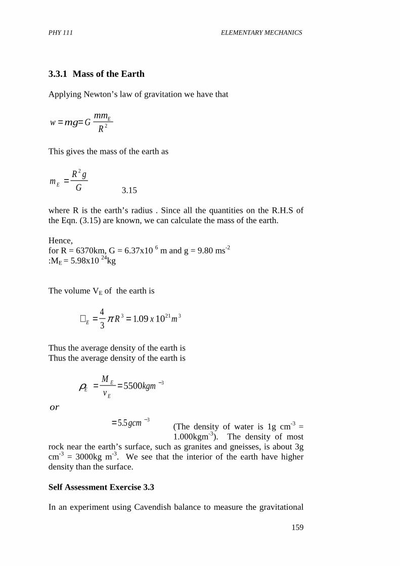
PHY 111 ELEMENTARY MECHANICS
159
3.3.1 Mass of the Earth Applying Newton’s law of gravitation we have that
This gives the mass of the earth as
3.15
where R is the earth’s radius . Since all the quantities on the R.H.S of the Eqn. (3.15) are known, we can calculate the mass of the earth. Hence, for R = 6370km, G = 6.37x10 6 m and g = 9.80 ms-2 :ME = 5.98x10 24kg The volume VE of the earth is
Thus the average density of the earth is Thus the average density of the earth is
(The density of water is 1g cm-3 = 1.000kgm-3). The density of most
rock near the earth’s surface, such as granites and gneisses, is about 3g cm-3 = 3000kg m-3. We see that the interior of the earth have higher density than the surface. Self Assessment Exercise 3.3 In an experiment using Cavendish balance to measure the gravitational
w mg Gmm
RE= = 2
mR g
GE =2
∨ = =E R x m4
3109 103 21 3π .
ρEE
E
M
vkgm
or
gcm
= =
=
−
−
5500
5 5
3
3.

PHY 111 ELEMENTARY MECHANICS
160
constant G, it is found that sphere of mass 0.8kg attracts another sphere of mass 0.004kg with a force 13 x 10-11 N when the distance between the centres of the spheres is 0.04m. The acceleration of gravity at the earth’s surface is 9.80 ms-2, and the radius of the earth is 6400km, compute the mass of the earth from these data. Solution The gravitational force between the objects of mass m1 and m2 is
where r is the distance between the centres of the spheres as given . Substituting other given values we have
�
mass of the earth will be given by
Self Assessment Exercise 3.4 The mass of the moon is about one eighty-first, and its radius one fourth, that of the earth. What is the acceleration due to gravity on the surface of the moon? Solution
We are given that mass of moon is, radius of mass
F Gm m
r= 1 2
2
Gx N x m
kg x kg
x Nm kg
=
=
−
− −
13 10 0 04
0 8 0004
6 5 10
11 2 2
11 2 2
( . )
. .
.
mR g
G
x m x ms
x Nm kg
x kg
x kg
E = =
=
=
−
− −
2 6 2 2 2
11 2 2
23
24
6 40 10 9 8
6 5 10
617551 10
6 2 10
( . ) .
.
.
.
M x x kgm =1
816 2 1024.
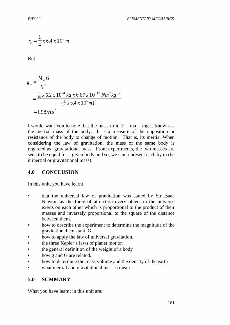
PHY 111 ELEMENTARY MECHANICS
161
But
I would want you to note that the mass m in F = ma = mg is known as the inertial mass of the body. It is a measure of the opposition or resistance of the body to change of motion. That is, its inertia. When considering the law of gravitation, the mass of the same body is regarded as gravitational mass. From experiments, the two masses are seen to be equal for a given body and so, we can represent each by m (be it inertial or gravitational mass). 4.0 CONCLUSION In this unit, you have learnt • that the universal law of gravitation was stated by Sir Isaac
Newton as the force of attraction every object in the universe exerts on each other which is proportional to the product of their masses and inversely proportional to the square of the distance between them.
• how to describe the experiment to determine the magnitude of the gravitational constant, G .
• how to apply the law of universal gravitation. • the three Kepler’s laws of planet motion • the general definition of the weight of a body • how g and G are related. • how to determine the mass volume and the density of the earth • what inertial and gravitational masses mean. 5.0 SUMMARY What you have learnt in this unit are:
r x x mm =1
46 4 106.
gM G
r
x x kg x x Nm kg
x x m
ms
mm
m
=
=
=
− −
−
2
118
24 11 2 2
14
6 2
2
6 2 10 6 67 10
6 4 10
198
. .
( . )
.
PHY 111 ELEMENTARY MECHANICS
162
• that every particle in the universe attracts every other particle with a force which is directly proportional to the product of their masses and inversely proportional to the square of their distances apart. Hence
• that in the expression for gravitational force above, that G is the universal gravitational constant and is the same everywhere
• that the Cavendish balance is used to determine G experimentally.
• that G has value 6.67 x 10⁻¹¹ Nm2 kg-2 • that acceleration due to gravity is not constant since the
gravitational force increases as • the spherical bodies approach each other. • that astronomical observations led Kepler to three laws of
planetary motion. 1. Planets move in planar elliptical paths with the sum at one focus
of the ellipse. 2. During equal time intervals, the radius vectors from the sun to the
planet sweeps out equal areas. 3. If T is the time it takes for a planet to make one full revolution
around the sun, and if R is half the major axes of the ellipse, (R reduces to the radius of the orbit of the planet if that orbit is circular) then.
where C is a constant whose value is the same for all planets. • Newton showed that these Keplers laws are a consequence of a
law of universal gravitation. • that the masses that exert gravitational forces are not always
point like. We can have an object with spherical mass distribution like the earth or sun. In this case, the gravitational force is the same as if all the mass of the extended object were concentrated at centre of the spherical distribution.
• that the Newtonian theory of gravity is a limiting case of a more accurate and
• fundamental theory of gravity. • that the weight of a body can be defined more generally as the
F Gm m
r= 1 2
2
T
RC
2
3 =
PHY 111 ELEMENTARY MECHANICS
163
resultant gravitational force exerted on the body by all other bodies in the universe.
i.e.
It follows that,
where the symbols have their usually meaning. • that weight varies from location to location • that the mass of the earth is given by
where R = radius of the earth, G = the universal constant and g is the acceleration due to gravity.
6.0 TUTOR MARKED ASSIGNMENT 1. State Newton’s law of Gravitation. If the acceleration due to
gravity, gm at the surface of the moon is 1.70 ms-2 and its radius is 1.74 x 10⁶m, calculate the mass of the moon.
2. Calculate the mass of the sun, assuming the Earth’s orbit around
the Sun is circular, with radius r = 1.5 x 10⁸ km. 3. Explain what is meant by the gravitation constant and describe an
accurate laboratory method of measuring it. Give an outline of the theory of your method. (i) The weight of a body on the surface of the earth is 900N.
What will be its weight on the surface of mars whose mass is 1/9 and radius ½ that of the earth
(ii) Mass of the moon Mm is given by 7.0 REFERENCES AND FURTHER READINGS Fishbane P .M ,Gasiorowicz S , and Thronton S .T , (1996)Physics for
scientists and engineers, {2nd ed.} Prentice Hall publ.New Jersey.
Sears F. W, Zemansky M .W and Young H..D(1975) College
w FGmM
RgE= = 2
gGM
RE= 2
mR g
GE =2
PHY 111 ELEMENTARY MECHANICS
164
Physics,{4th Ed}Addison-Wesley publ. co. Reading, U.K. Nelkon M and Parker P(1970) Advanced Level Physics, Heinemann
Educational Books Ltd ., London. Duncan T. (1980) Physics A text book for Advanced Level Students
John Murray (publishers) Ltd .London UNIT 12: ORBITAL MOTION UNDER GRAVITY CONTENTS 1.0 Introduction 2.0 Objectives 3.0 Main Body
PHY 111 ELEMENTARY MECHANICS
165
3.1 Motion in a Vertical Circle 3.2 Motion of a Satellite 3.3 Parking Orbit 3.4 Weightlessness
4.0 Conclusion 5.0 Summary 6.0 Tutor Marked Assignment (TMA) 7.0 References and Further Reading 1.0 INTRODUCTION In this Unit, we shall continue our discussion on gravitation, commenced in unit 11. Particularly shall we focus on orbital motion under gravity beginning with motion in a vertical circle. We shall then discuss motion of a satellite and identify possible trajectories a satellite can have. You will learn to determine the velocity of a satellite in its orbit as well as its period of revolution by applying the knowledge of gravitational force on the satellite. We shall end with the introduction of concept of parking orbit and weightlessness. This unit will let you have a feel of what astronauts experience when they are projected into space. The next Unit will enlighten you as to the velocity an object or a satellite can have before it could be able to escape from the surface of the earth. You will see that Science stimulates one to take giant steps and do giant things to move the world forward. Positioning telecommunication satellite in space is an example of how science has turned this vast world into a global village whereby communication has been successfully trivialised.
2.0 OBJECTIVES By the end of this unit, you should be able to • determine normal radial and tangential accelerations of a body in
vertical circular motion • describe the motion of a satellite in an orbit in terms of the
velocity and period. • state at least one application of a parking orbit. • explain the concept of weightlessness • calculate the magnitude and direction of an impulse needed to
launch a satellite in space given all necessary requirements 3.0 MAIN BODY 3.1 Motion in a Vertical Circle Figure 3.1 represents a small body attached to a cord of length R and whirling in a vertical circle about a fixed point 0 to which the other end
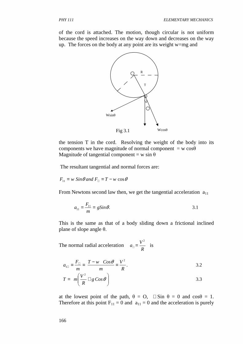
PHY 111 ELEMENTARY MECHANICS
166
of the cord is attached. The motion, though circular is not uniform because the speed increases on the way down and decreases on the way up. The forces on the body at any point are its weight w=mg and the tension T in the cord. Resolving the weight of the body into its components we have magnitude of normal component = w cosθ Magnitude of tangential component = w sin θ The resultant tangential and normal forces are:
θθ cos11 wTFandSinwF −== ⊥ From Newtons second law then, we get the tangential acceleration a11
1.3.1111 θgSin
m
Fa ==
This is the same as that of a body sliding down a frictional inclined plane of slope angle θ.
The normal radial acceleration R
Va
2
=⊥ is
3.3
2.3.
2
2
1
+=
=−== ⊥⊥
θ
θ
CosgR
VmT
R
V
m
CoswT
m
Fa
at the lowest point of the path, θ = O, ∴Sin θ = 0 and cosθ = 1. Therefore at this point F11 = 0 and a11 = 0 and the acceleration is purely
Wcosθ
T
R
Wsinθ
Fig 3.1
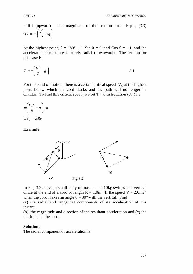
PHY 111 ELEMENTARY MECHANICS
167
radial (upward). The magnitude of the tension, from Eqn.., (3.3)
is
+= g
R
VmT
2
At the highest point, θ = 180° ∴ Sin θ = O and Cos θ = - 1, and the acceleration once more is purely radial (downward). The tension for this case is
4.3.2
−= g
R
VmT
For this kind of motion, there is a certain critical speed VC at the highest point below which the cord slacks and the path will no longer be circular. To find this critical speed, we set T = 0 in Equation (3.4) i.e.
RgV
gR
Vm
C
C
=∴
=
− 0
2
Example In Fig. 3.2 above, a small body of mass m = 0.10kg swings in a vertical circle at the end of a cord of length R = 1.0m. If the speed V = 2.0ms-1 when the cord makes an angle θ = 30° with the vertical. Find (a) the radial and tangential components of its acceleration at this instant. (b) the magnitude and direction of the resultant acceleration and (c) the tension T in the cord. Solution: The radial component of acceleration is
θ
θ
(a)
(b)
Fig 3.2
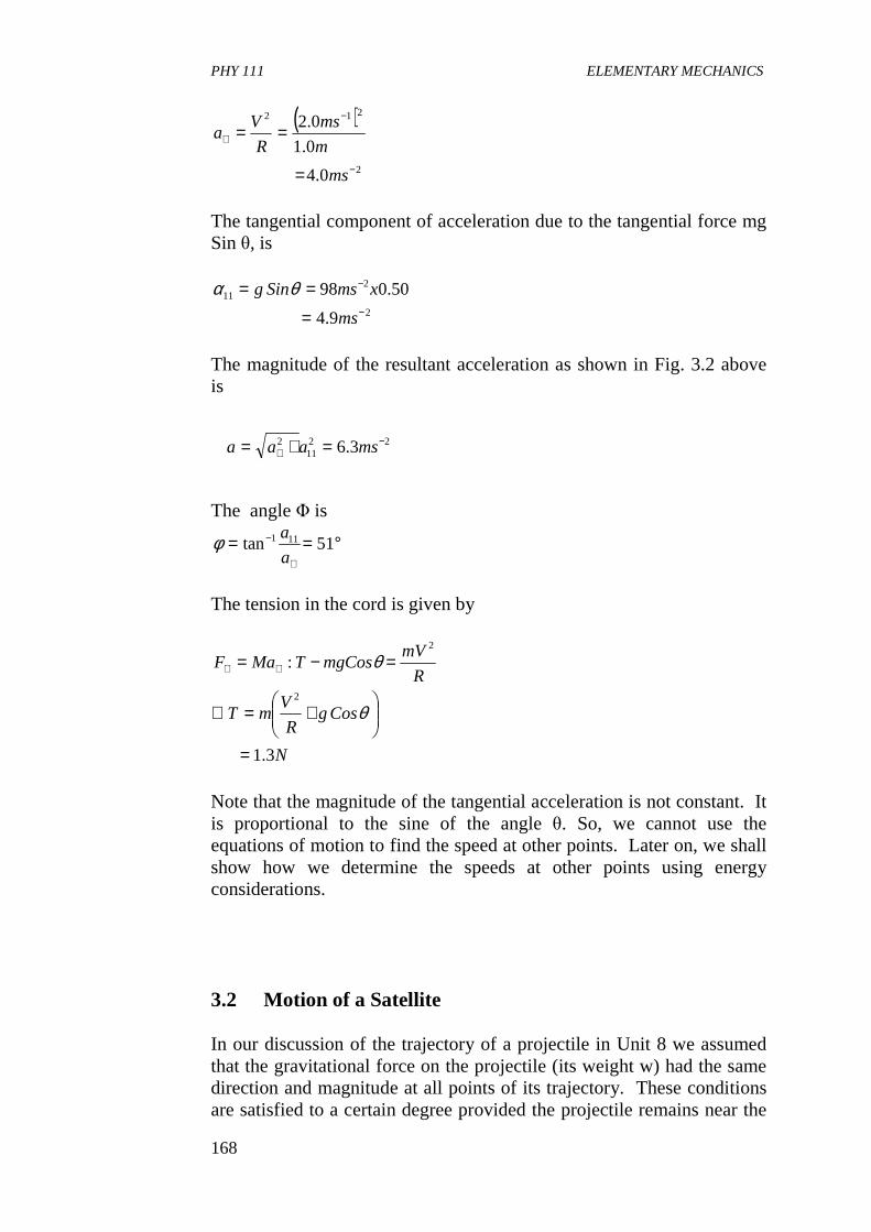
PHY 111 ELEMENTARY MECHANICS
168
( )
2
212
0.4
0.1
0.2
−
−
⊥
=
==
ms
m
ms
R
Va
The tangential component of acceleration due to the tangential force mg Sin θ, is
2
211
9.4
50.098−
−
=
==
ms
xmsSing θα
The magnitude of the resultant acceleration as shown in Fig. 3.2 above is
2211
2 3.6 −⊥ =+= msaaa
The angle Φ is
°==⊥
− 51tan 111
a
aφ
The tension in the cord is given by
N
CosgR
VmT
R
mVmgCosTMaF
3.1
:
2
2
=
+=∴
=−= ⊥⊥
θ
θ
Note that the magnitude of the tangential acceleration is not constant. It is proportional to the sine of the angle θ. So, we cannot use the equations of motion to find the speed at other points. Later on, we shall show how we determine the speeds at other points using energy considerations. 3.2 Motion of a Satellite In our discussion of the trajectory of a projectile in Unit 8 we assumed that the gravitational force on the projectile (its weight w) had the same direction and magnitude at all points of its trajectory. These conditions are satisfied to a certain degree provided the projectile remains near the
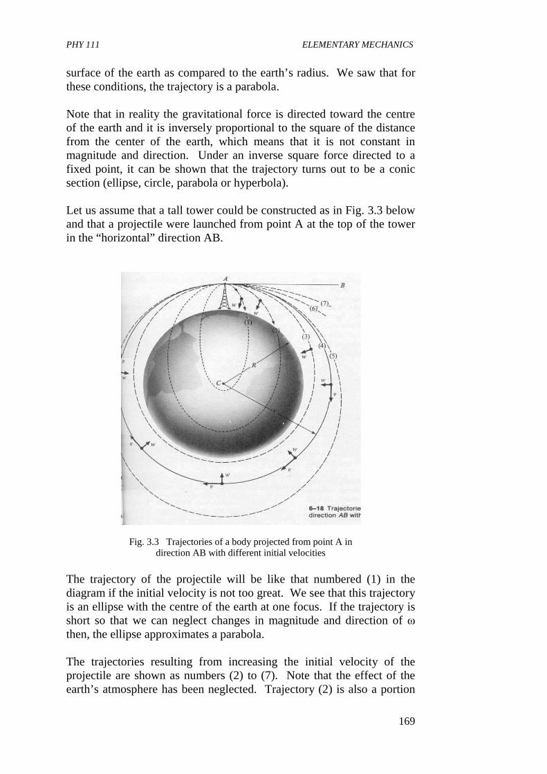
PHY 111 ELEMENTARY MECHANICS
169
surface of the earth as compared to the earth’s radius. We saw that for these conditions, the trajectory is a parabola. Note that in reality the gravitational force is directed toward the centre of the earth and it is inversely proportional to the square of the distance from the center of the earth, which means that it is not constant in magnitude and direction. Under an inverse square force directed to a fixed point, it can be shown that the trajectory turns out to be a conic section (ellipse, circle, parabola or hyperbola). Let us assume that a tall tower could be constructed as in Fig. 3.3 below and that a projectile were launched from point A at the top of the tower in the “horizontal” direction AB.
Fig. 3.3 Trajectories of a body projected from point A in direction AB with different initial velocities
The trajectory of the projectile will be like that numbered (1) in the diagram if the initial velocity is not too great. We see that this trajectory is an ellipse with the centre of the earth at one focus. If the trajectory is short so that we can neglect changes in magnitude and direction of ω then, the ellipse approximates a parabola. The trajectories resulting from increasing the initial velocity of the projectile are shown as numbers (2) to (7). Note that the effect of the earth’s atmosphere has been neglected. Trajectory (2) is also a portion
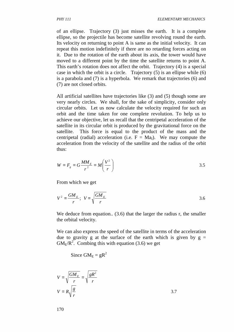
PHY 111 ELEMENTARY MECHANICS
170
of an ellipse. Trajectory (3) just misses the earth. It is a complete ellipse, so the projectile has become satellite revolving round the earth. Its velocity on returning to point A is same as the initial velocity. It can repeat this motion indefinitely if there are no retarding forces acting on it. Due to the rotation of the earth about its axis, the tower would have moved to a different point by the time the satellite returns to point A. This earth’s rotation does not affect the orbit. Trajectory (4) is a special case in which the orbit is a circle. Trajectory (5) is an ellipse while (6) is a parabola and (7) is a hyperbola. We remark that trajectories (6) and (7) are not closed orbits. All artificial satellites have trajectories like (3) and (5) though some are very nearly circles. We shall, for the sake of simplicity, consider only circular orbits. Let us now calculate the velocity required for such an orbit and the time taken for one complete revolution. To help us to achieve our objective, let us recall that the centripetal acceleration of the satellite in its circular orbit is produced by the gravitational force on the satellite. This force is equal to the product of the mass and the centripetal (radial) acceleration (i.e. F = MaI). We may compute the acceleration from the velocity of the satellite and the radius of the orbit thus:
5.32
2
===
r
VM
r
MMGFW E
g
From which we get
6.3;2
r
GMV
r
GMV EE ==
We deduce from equation.. (3.6) that the larger the radius r, the smaller the orbital velocity. We can also express the speed of the satellite in terms of the acceleration due to gravity g at the surface of the earth which is given by g = GME/R2. Combing this with equation (3.6) we get Since GME = gR2
7.3
2
r
gRV
r
gR
r
GMV E
=
==
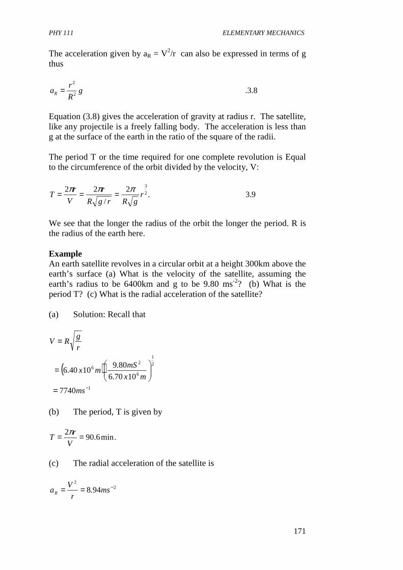
PHY 111 ELEMENTARY MECHANICS
171
The acceleration given by aR = V2/r can also be expressed in terms of g thus
8.3.2
2
gR
raR =
Equation (3.8) gives the acceleration of gravity at radius r. The satellite, like any projectile is a freely falling body. The acceleration is less than g at the surface of the earth in the ratio of the square of the radii. The period T or the time required for one complete revolution is Equal to the circumference of the orbit divided by the velocity, V:
9.3.2
/
222
3
rgRrgR
r
V
rT
πππ ===
We see that the longer the radius of the orbit the longer the period. R is the radius of the earth here. Example An earth satellite revolves in a circular orbit at a height 300km above the earth’s surface (a) What is the velocity of the satellite, assuming the earth’s radius to be 6400km and g to be 9.80 ms-2? (b) What is the period T? (c) What is the radial acceleration of the satellite? (a) Solution: Recall that
( )1
2
1
6
26
7740
1070.6
80.91040.6
−=
=
=
ms
mx
mSmx
r
gRV
(b) The period, T is given by
.min6.902 ==V
rT
π
(c) The radial acceleration of the satellite is
22
94.8 −== msr
VaR
PHY 111 ELEMENTARY MECHANICS
172
This is equal to the free fall acceleration at a height of 300km above the earth. Self Assessment Exercise 3.1 An earth satellite rotates in a circular orbit of radius 6600km (about 600km above the earth’s surface) with an orbital speed of 425km min-1 (a) Find the time of revolution (b) Find the acceleration of gravity at the orbit Solution (a) Recall that period T is given by
min6.97
min425
6600221
=∴
== −
T
km
km
V
rT
ππ
(b) Recall that r
VaR
2
=
( )
2
2
21
6.7
6060
100036.27
36.27
425.
−
−
−
=
=
=
=
mS
x
mx
mkm
r
mkmaei R
3.3 Parking Orbit Consider a satellite of mass m revolving round the earth in the plane of the equator in an orbit 2 concentric with the earth as represented in the Figure 3.4 below Let us suppose the direction of rotation is the same as the earth and the orbit is at a distance R from the centre of the earth. Assume V to be the velocity of the satellite in orbit, then Centripetal force = Fg
Orbit 1
Orbit
2
Earth Satellite
Fig 3.4
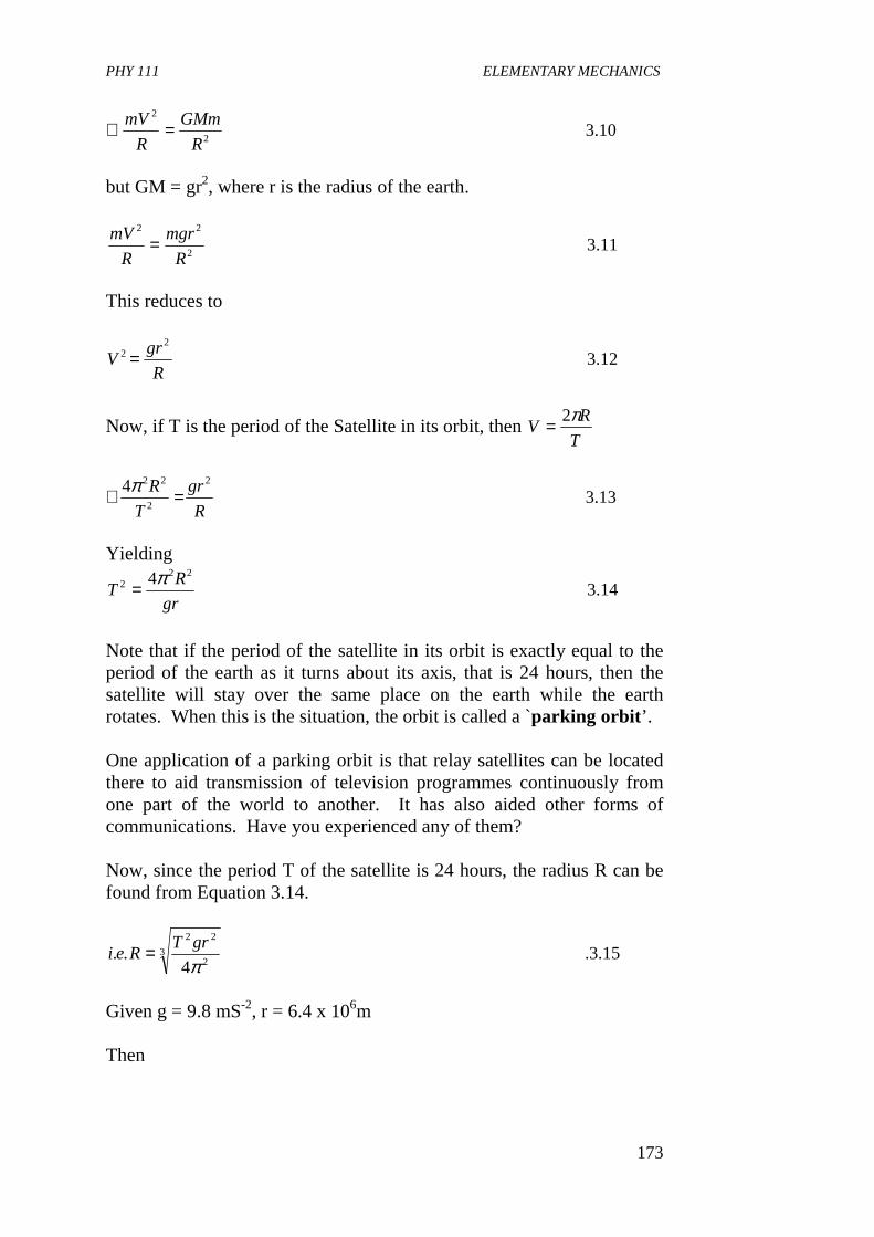
PHY 111 ELEMENTARY MECHANICS
173
10.32
2
R
GMm
R
mV =∴
but GM = gr2, where r is the radius of the earth.
11.32
22
R
mgr
R
mV =
This reduces to
12.32
2
R
grV =
Now, if T is the period of the Satellite in its orbit, then T
RV
π2=
13.34 2
2
22
R
gr
T
R =∴ π
Yielding
14.34 22
2
gr
RT
π=
Note that if the period of the satellite in its orbit is exactly equal to the period of the earth as it turns about its axis, that is 24 hours, then the satellite will stay over the same place on the earth while the earth rotates. When this is the situation, the orbit is called a p̀arking orbit ’. One application of a parking orbit is that relay satellites can be located there to aid transmission of television programmes continuously from one part of the world to another. It has also aided other forms of communications. Have you experienced any of them? Now, since the period T of the satellite is 24 hours, the radius R can be found from Equation 3.14.
15.3.4
.. 32
22
πgrT
Rei =
Given g = 9.8 mS-2, r = 6.4 x 10⁶m Then
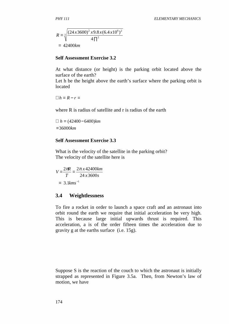
PHY 111 ELEMENTARY MECHANICS
174
km
xxxxR
42400
4
)104.6(8.9)360024(3
2
262
=∏
=
Self Assessment Exercise 3.2 At what distance (or height) is the parking orbit located above the surface of the earth? Let h be the height above the earth’s surface where the parking orbit is located
=−=∴ rRh where R is radius of satellite and r is radius of the earth
km
kmh
36000
)640042400(
=−=∴
Self Assessment Exercise 3.3 What is the velocity of the satellite in the parking orbit? The velocity of the satellite here is
11.3
360024
4240022
−=
==
kms
sx
kmx
T
RV
ππ
3.4 Weightlessness To fire a rocket in order to launch a space craft and an astronaut into orbit round the earth we require that initial acceleration be very high. This is because large initial upwards thrust is required. This acceleration, a is of the order fifteen times the acceleration due to gravity g at the earths surface (i.e. 15g). Suppose S is the reaction of the couch to which the astronaut is initially strapped as represented in Figure 3.5a. Then, from Newton’s law of motion, we have
PHY 111 ELEMENTARY MECHANICS
175
F = ma, S – mg = ,ma = m.15g, Where m is the mass of the astronaut. Thus S = 16mg. This means that the reaction force S is 16 times the weight of the astronaut so he or she experiences a large force on take off. Once they are in orbit the sceriario (changes). Here, the acceleration of the space craft and the astronaut becomes g1 in magnitude where g1 is the acceleration due to gravity at the particular height of the orbit outside the space craft. Now, if S1 represents the reaction of the surface of the space craft in contact with the astronaut, the circular motion gives
01
111
=∴==−=
S
mgmaSmgF
Hence the astronaut becomes “weightless’ because he or she experiences no reaction at the floor when he walks about. At the surface of the earth, we are conscious of our weight because we experience the reaction at the ground where we are standing or on the chair where we are sitting. Do you feel your weight as you are reading this Unit? Think of it and you become conscious of it. When you jump up, what happens? What do you feel when you are inside a lift (or an elevator} that takes people up and down a many storey building?). If the lift descends freely, the acceleration of objects inside it is the same as that outside. So the reaction on them is zero. The people inside it then experience a sensation of `weightlessness”. In orbit as shown in Figure 3.5 b, objects inside a space craft are also in `free fall’. This is because they have the same acceleration g´ as the space craft so they feel the sensation of `weightlessness’. Do you now understand what brings about the phenomenon of `weightlessness’? Read this section again, thoroughly well. Aim to take a trip to a building with an elevator and get a ride in it. `Weightlessness’ is an experience worth feeling. `Good luck’! Example A satellite is to be put into orbit 500km above the earth’s surface. If its vertical velocity after launching is 2000ms-1 at this height, calculate the magnitude and direction of the impulse required to put the satellite directly into orbit, if its mass is 50kg. Assume g = 10ms-2, radius of earth, R = 6400km. Solution Suppose u is the velocity required for an orbit, of radius r. Then with our usual notation,
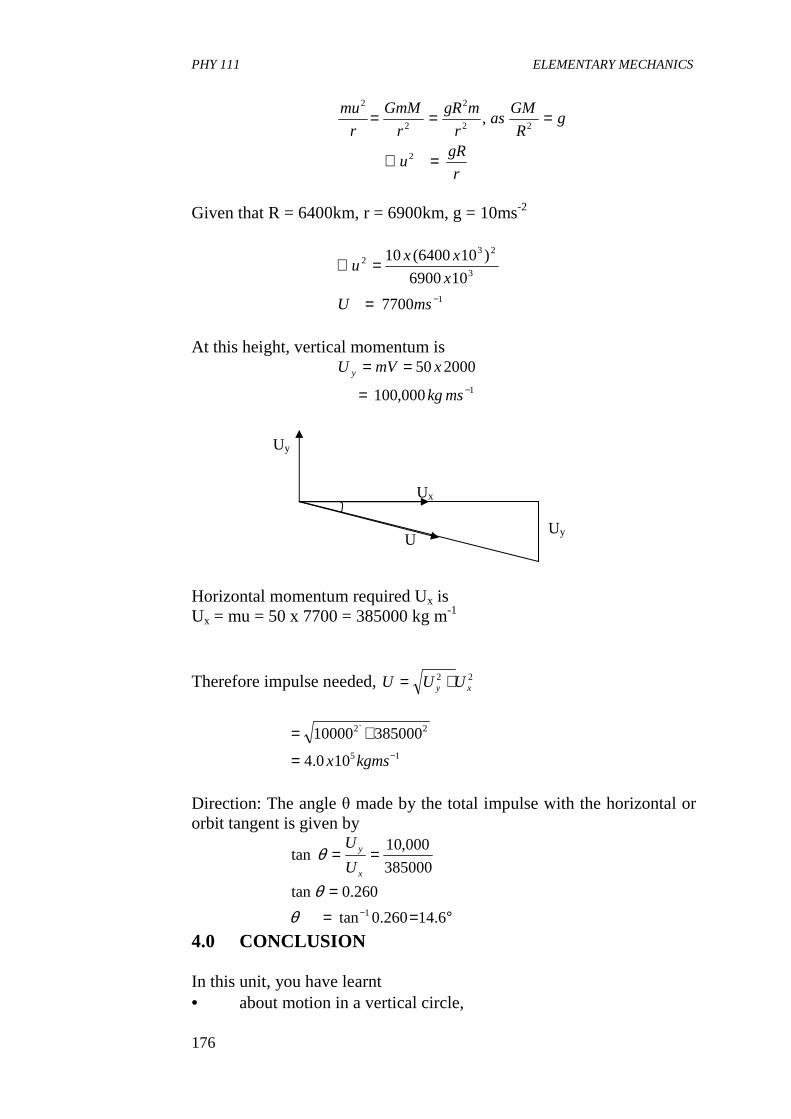
PHY 111 ELEMENTARY MECHANICS
176
r
gRu
gR
GMas
r
mgR
r
GmM
r
mu
=∴
===
2
22
2
2
2
,
Given that R = 6400km, r = 6900km, g = 10ms-2
1
3
232
7700
106900
)106400(10
−=
=∴
msU
x
xxu
At this height, vertical momentum is
1000,100
200050−=
==
mskg
xmVU y
Horizontal momentum required Ux is Ux = mu = 50 x 7700 = 385000 kg m-1
Therefore impulse needed, 22xy UUU +=
15
2`2
100.4
38500010000−=
+=
kgmsx
Direction: The angle θ made by the total impulse with the horizontal or orbit tangent is given by
°===
==
− 6.14260.0tan
260.0tan
385000
000,10tan
1θθ
θx
y
U
U
4.0 CONCLUSION In this unit, you have learnt • about motion in a vertical circle,
Uy
U Uy
Ux
PHY 111 ELEMENTARY MECHANICS
177
- that it is not a uniform motion - that here, speed increases on the way down but decreases
on the way up for a particle undergoing such a motion. • that the resultant tangential and normal forces are F = ω Sinθ and
F = T- ω cosθ where T is the tension in the string holding the particle
• that satellites revolve round the sun in orbit, that turn out to be conic sections (ellipse, circle, parabola or hyperbola).
• that the centripetal acceleration of the satellite in its circular orbit is produced by the gravitational force on the satellite.
• that this force is Equal to the mass times the radial acceleration
⊥= maF
r
Vawhere
r
Vm
r
GmMFei E
g
2
2
2.
=
===
⊥
ω
• that the velocity of the orbiting satellite
is gR
raand
r
GMV R
E .2
22 ==
• that the period of revolution is
gR
r
V
rT
2
3
22 ππ ==
• that a parking orbit is the orbit of a satellite whose period of
revolution is approximately Equal to the period of rotation of the earth about its axis which is 24 hours
• that satellites in parking orbit are used as relay satellites for TV and other forms of communications.
• that great acceleration is needed to fire a rocket in order to launch a satellite or space craft with astronauts.
• that when there is no reaction force to an object’s weight, the object feels weightless.
5.0 SUMMARY What you have learnt in this unit are: • that in a vertical motion, the tangential force is F11 = w Sinθ and
the radial force is F1 = w cosθ. Where T is the tension in the string and w = mg is the weights of the object in circular motion. The resultant tangential and normal forces are
θθ cos11 wTFandSinwF −== ⊥
PHY 111 ELEMENTARY MECHANICS
178
• that the path described by a satellite round the sun is a conical
section (ellipse, circle, parabola or hyperbola). That the normal radial acceleration is
•
+=∴
−===⊥
θ
θ
CosgR
VmT
m
wT
m
F
R
Va
2
12 cos
At the lowest point of the path, θ = 0 Therefore Sin θ = 0 and Cos θ = 1 and the acceleration is purely radial (upwards). The magnitude of the tension is then
+= g
R
VmT
2
At the highest point θ = 1800, Sin θ = 0 and Cos θ = -1, and the acceleration is once more purely radial (downwards).
−= g
R
VmT
2
For this kind of motion, there is a critical point below which the cord slacks and the path will no longer be circular. This happened at T = 0
RgV
gR
Vm
C =∴
=
− 0
2
• that the gravitational force on a satellite produces the centripetal
(radial) acceleration that keeps the satellite in orbit
• that the velocity of the orbiting satellite is given by r
GMV E=
Where ME is mass of the earth, G is the gravitational constant and r is the radius of the satellite.
• that its acceleration is gR
raor
r
Va R 2
22
==
• that the period of revolution of a satellite is
gR
r
V
rT
2
3
22 ππ ==
PHY 111 ELEMENTARY MECHANICS
179
• that if a satellite is in its parking orbit round the earth, it will remain at the same place while the earth rotates because in its parking orbit its period of revolution is same as the period of revolution of the earth. That is why it is called the parking orbit for the satellite
• the radius of the satellite in its parking orbit is given by
32
22
4πgrT
R =
where r is the radius of the earth, T = 24h
• the velocity of the satellite in its parking orbit is T
RV
π2=
• the height of the parking orbit above the surface of the earth is rRh −=
• that when the reaction force to the force of gravity is zero, the object feels weightless.
6.0 TUTOR MARKED ASSIGNMENTS 1. A satellite is to be sent to the position between the moon and
Earth where there is no net gravitational force on an object due to those two bodies. Locate that point.
2. What is the period of revolution of a manmade Satellite of mass m which is orbiting the earth in a circular path of radius 8000km? (mass of earth = 5.98 x 1024kg)
7.0 REFERENCES AND FURTHER READING Sears, F.W., Zemansky M.W and Young H.D (1975) College Physics, Fourth Ed.Addison-Wesley publ. Co, Reading, U.K Indira Ghandi National Open University School of Sciences PHE – 01,
Elementary Mechanics – Concepts in Mechanics. Fishbane , P.M., Gasiorowicz, S. and Three S.T, (1996) Physics for
Scientists and Engineers, 2nd Ed. Prentice Hall, New Jersey. Nelkon M and Parker P (1970) Advanced Level Physics Heinemann
Educational Books Ltd. London. Duncan T.(1982) Physics A Textbook for Advanced Level Students.
John Murray Publishers Ltd., London.

PHY 111 ELEMENTARY MECHANICS
180
UNIT 3 GRAVITATION AND EXTENDED BODIES CONTENTS 1.0 Introduction 2.0 Objectives 3.0 Main Body
3.1 Gravitational Potential Energy
PHY 111 ELEMENTARY MECHANICS
181
3.2 Escape Speed 3.3 Variation of g With Height and Depth 3.4 Variation of g With Latitude 3.5 Fundamental Forces in Nature
4.0 Conclusion 5.0 Summary 6.0 Tutor Marked Assignment (TMA) 7.0 References and Further Reading 1.0 INTRODUCTION In this unit, our study of the universal gravitation will be concluded with a look at gravitation and extended bodies. You will learn how to determine gravitational potential energy and escape speed or velocity of a satellite to be projected into space, we shall discuss the variation of gravitational force with height, depth and latitude. Finally we shall visualise the gravitational force as a fundamental force in nature. This will bring us to what opposes motion of an object in the next Unit titled Friction. 2.0 OBJECTIVES By the end of this Unit, you should be able to:
• compute the gravitational potential. • derive expression for escape speed • solve problems related to the variation of acceleration due to
gravity with the height, depth and latitude of a place • distinguish between the fundamental forces in nature.
3.0 MAIN BODY 3.1 Gravitational Potential Energy We have seen in Unit 12 that gravitational force is a central force and depends only on the distance of the influenced object from the force center. Since it is a conservative force it can be derived from a potential energy function. We shall show here that the potential energy of a system of two point masses interacting with each other through the gravitational force is rGmMrU )()( −= . Let the potential energy at infinity be zero. Now, potential energy is defined as
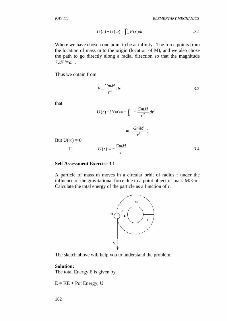
PHY 111 ELEMENTARY MECHANICS
182
1.3.)()()( ∫ ∞=∞− drrFUrUr rr
Where we have chosen one point to be at infinity. The force points from the location of mass m to the origin (location of M), and we also chose the path to go directly along a radial direction so that the magnitude
..ˆ 11 drrdr =r
Thus we obtain from
2.32
rdr
GmMF
)r=
that
r
r
r
GmM
drr
GmMUrU
∞
∞
−=
−−=∞− ∫
|
)()(
1
12
But U(∞) = 0
4.3)(r
GmMrU −=∴
Self Assessment Exercise 3.1 A particle of mass m moves in a circular orbit of radius r under the influence of the gravitational force due to a point object of mass M>>m. Calculate the total energy of the particle as a function of r. The sketch above will help you to understand the problem, Solution: The total Energy E is given by E = KE + Pot Energy, U
m
M
r
v
f
PHY 111 ELEMENTARY MECHANICS
183
−+=+r
GmMmvUKE 2
2
1
We see it’s a function of both V and r. We want to eliminate the speed. We achieve this by applying F = ma. For a circular orbit, the
acceleration is centripetal and is of the form r
Va
2
= and directed
towards the centre. The force has the magnitude 2r
GmM and is also
directed to the centre. Newton’s second law therefore has the form
r
GMvor
r
mv
r
GmM
=
=
2
2
2
We use this expression for v2 to eliminate the speed in the expression for total energy to get
r
GmMr
GmM
r
GMm
r
GmMmvE
2
12
1
2
1 2
−=
−=−=
This means that the total energy is just one-half the potential energy for a circular orbit. The value is negative. This is appropriate because the orbit is closed. 3.2 Escape Speed What happens when you throw a ball vertically upward? Does it continue going up forever? We notice that the faster a ball is thrown upwards, the higher it rises before falling backwards. It falls backwards due to the pull of gravity on it. This concept you studied in Units 11 and 12. In this unit, we shall find out the value of an initial velocity an object can have in order to be able to escape from the surface of the earth into space. That is the velocity or speed we refer to as escape speed or escape velocity. To project an object (satellite) and land it say, on the moon, it could first be projected to land on an orbit whose period of revolution is same as time taken for the earth to rotate about its axis i.e. 24 hours (this orbit is referred to as parking orbit for the satellite) with a speed of 8kms-1 and then subsequently firing the rocket again to reach escape speed in the appropriate direction to land on the moon.
PHY 111 ELEMENTARY MECHANICS
184
To obtain the escape speed we use the following analysis. We know that a certain amount of energy is required to escape from the earth. The escape speed will be determined considering the fact that the potential energy gained by the satellite will be equal to the kinetic energy lost if we neglect air resistance. Let m be the mass of the escaping body and M the mass of the earth. The force F exerted on the body by the earth when the distance separating them is x from the earth’s center is given by
5.32x
MmGF =
Work done, δW by gravity when the body moves a distance dx upwards is
6.3.2
dxx
MmGFdxW −=−=δ
The negative sign shows that the force acts in the opposite direction to displacement therefore,. Total work done while body escapes =
7.32
dxx
MmG
r−∫
∞
where r = radius of the earth
[ ]
8.3
11
r
GMm
xGMmGMmdoneWorkTotal
rrx
=
=−−=∴∞
∞
If the body leaves the earth with speed v and just escapes from its gravitational field then, KE = Potential Energy.
9.32
1.. 2
r
GMmmvei =
ar
GMv 10.3
2=∴
But 2r
GMg =
PHY 111 ELEMENTARY MECHANICS
185
Substituting, we get bgrv 10.32=
Eqn. (3.10) gives the expression for the velocity of escape. Substituting the values of g = 9.8mx, s-2 and r = 6.4 x 10 6 m the escape speed is calculated to be
111 −≈ skmV We conclude that with an initial velocity of about 11km s-1, a rocket will completely escape from the gravitational attraction of the earth. It can be directed to land on the moon so that it eventually will be under the influence of the moons gravity. At present `soft’ landings on the moon have been achieved by firing retarding retro rockets. Possible paths for a body projected at different speeds from the earth have already been given in Fig 3.3 of Unit 12. Summarising we note that with a velocity of about 8km s-1, a satellite can describe a circular orbit close to the surface of the earth. When the velocity is greater than 8kms-1 but less than 11km s-1, a satellite describes an ecliptical orbit round the earth. We note that its maximum and minimum height in the orbit depends on its particular velocity. Air molecules at standard temperature and pressure posses an average speed of about 0.5kms-1. This is much less than the escape speed so the earth’s gravitational field is able to maintain an atmosphere of air round the earth. On the other hand, hydrogen molecules are rare in the earth’s atmosphere because their average speed is three times that of air molecules. The moon has no atmosphere. (i) Can you suggest why it is so? (ii) Why does the earth retain its atmosphere? Self Assessment Exercise 3.2 Find the velocity or speed of escape on the surface of the moon? Solution The speed of escape on the moon Vem is
mem r
GMmV
2=
PHY 111 ELEMENTARY MECHANICS
186
16
2211
2211
622
106.1
1065.71067.62
1067.6
106.11065.7
−−
−−
=
=
==
msx
xxxxV
kgmNxG
mxrandkgxMIf
em
mm
131053.2 −= msx 3.3 Variation of g With Height and Depth
Let us assume that g is the acceleration due to gravity at a distance a from the centre of the earth where a >r. r is the radius of the earth. Then from our studies on weight in Unit 11 we had that
11.3'2
2
a
GMgHence
r
GMg
E
E
=
=
where ME is the mass of the earth and G is the universal gravitation constant.
Dividing 12.3.'
2
2
a
r
g
g =
Or
13.3'2
2
ga
rg =
From Eqn 3.9, we conclude that, above the earth’s surface, the acceleration due to gravity g′ varies inversely as the square of the distance, a between the object and the center of the earth. Note that in the same equation r and g are constants. g′ thus decreases with height as shown in Fig 3.1 below.
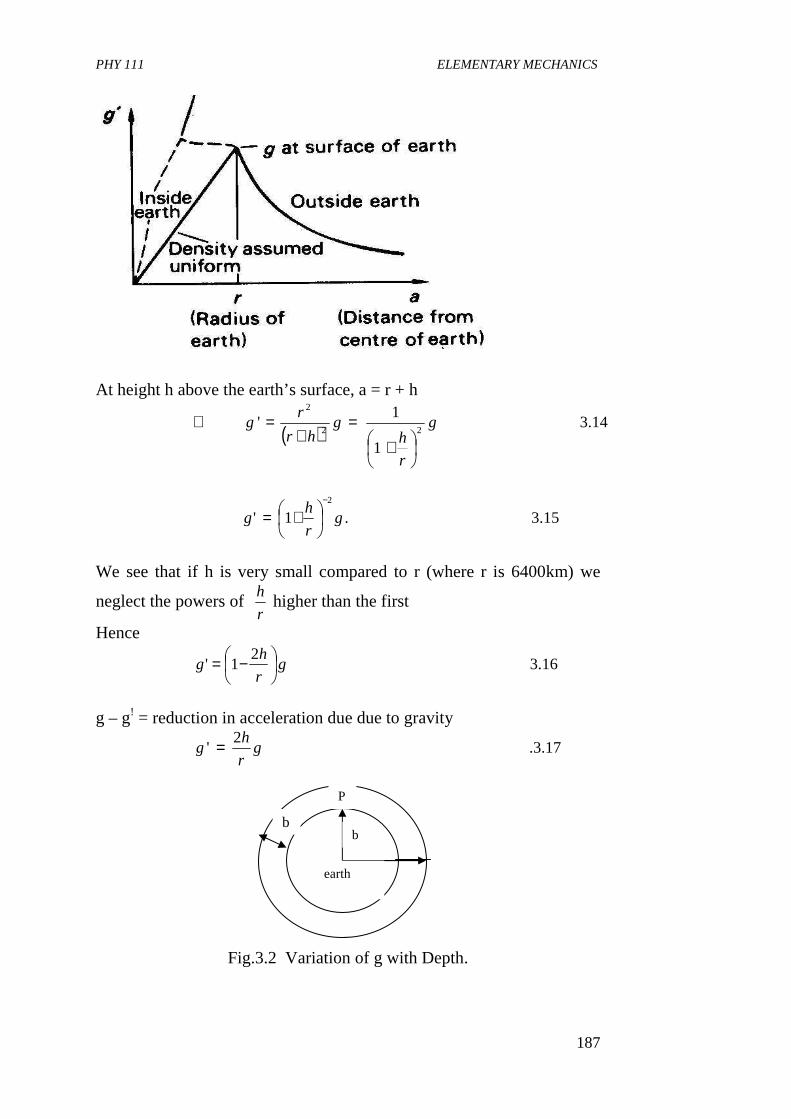
PHY 111 ELEMENTARY MECHANICS
187
At height h above the earth’s surface, a = r + h
( )14.3
1
1'
22
2
g
r
hg
hr
rg
+=
+=∴
15.3.1'2
gr
hg
−
+=
We see that if h is very small compared to r (where r is 6400km) we
neglect the powers of r
h higher than the first
Hence
16.32
1' gr
hg
−=
g – g! = reduction in acceleration due due to gravity
17.3.2
' gr
hg =
Fig.3.2 Variation of g with Depth.
P
b b
earth
PHY 111 ELEMENTARY MECHANICS
188
At a point say p below the earth’s surface it can be shown that if the shaded spherical sheet in Fig 3.2 is of uniform density, it produces no gravitational field inside itself. The gravitational acceleration g, at point p is then due to the sphere of radius b. If we assume this sphere to be of uniform density, then from our knowledge of the relation between g and G we have
18.322
11 r
GMgand
b
GMg ==
where M1 is the mass of the sphere of radius b. The mass of a uniform sphere is proportional to its radius cubed, hence
19.33
31
r
b
M
M =
But
2
211
b
r
M
M
g
g =
20.3.1
r
b
g
g =∴
or
21.31 gr
bg =
Thus, assuming the earth has uniform density, the acceleration due to gravity g is directly proportional to the distance b from the center. That is, it decreases linearly with depth, Fig. (3.1). At depth h below the earth’s surface, b = r – h
22.311 gr
hg
r
hrg
−=
−=∴
But because the density of the earth is not constant, g, actually increases for all depths now obtainable as shown by part of the dotted curve in Fig. 3.1 Self Assessment Exercise 3.3 If r is the radius of the earth and g is the acceleration at its surface, what is the expression for the acceleration of g1 of a satellite at an orbit a distance R from the Centre of the earth. R>>r
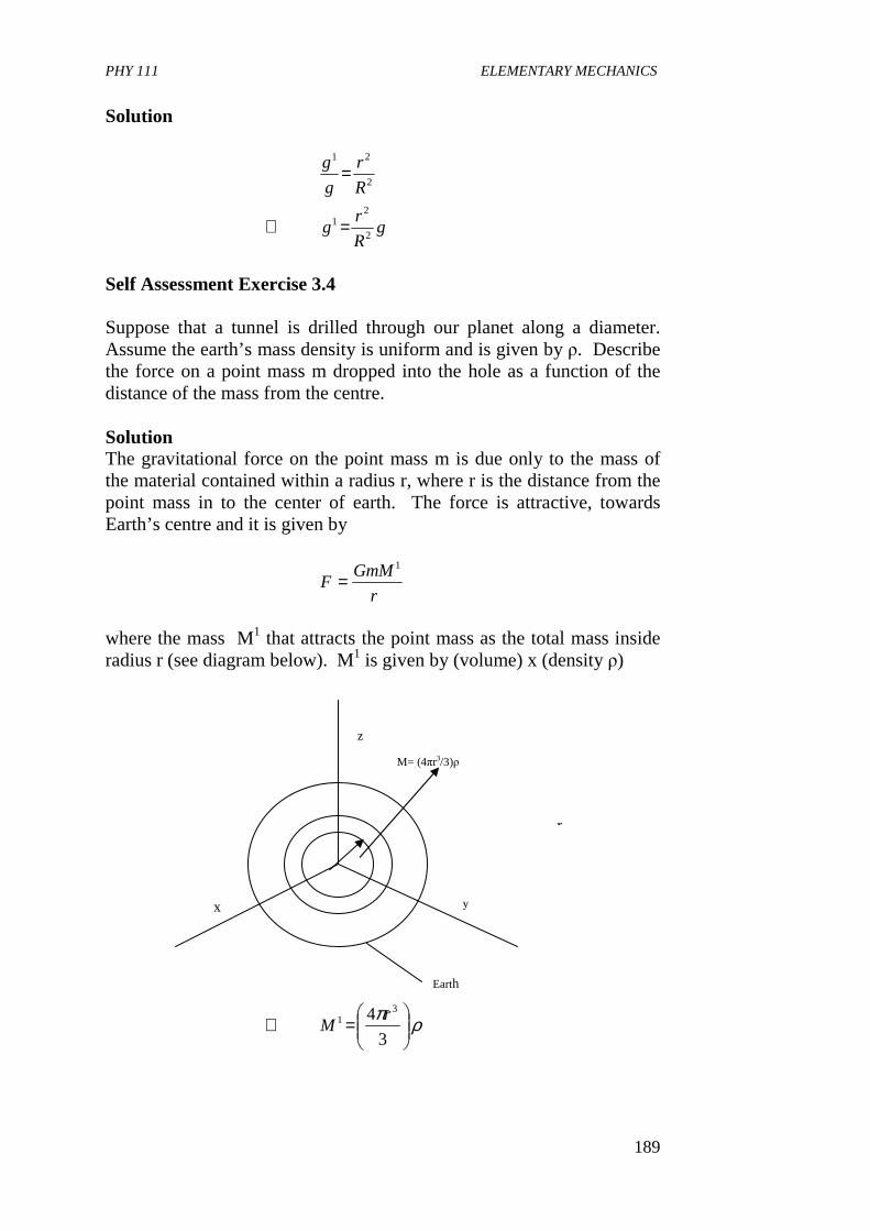
PHY 111 ELEMENTARY MECHANICS
189
Solution
gR
rg
R
r
g
g
2
21
2
21
=∴
=
Self Assessment Exercise 3.4 Suppose that a tunnel is drilled through our planet along a diameter. Assume the earth’s mass density is uniform and is given by ρ. Describe the force on a point mass m dropped into the hole as a function of the distance of the mass from the centre. Solution The gravitational force on the point mass m is due only to the mass of the material contained within a radius r, where r is the distance from the point mass in to the center of earth. The force is attractive, towards Earth’s centre and it is given by
r
GmMF
1
=
where the mass M1 that attracts the point mass as the total mass inside radius r (see diagram below). M1 is given by (volume) x (density ρ)
ρπ
=∴
3
4 31 r
M
y x
Earth
M= (4πr3/3)ρ
z
r
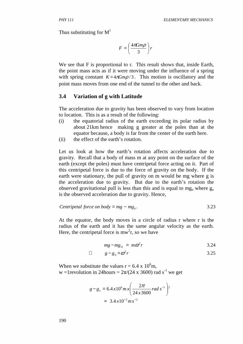
PHY 111 ELEMENTARY MECHANICS
190
Thus substituting for M1
rGm
F
=3
4 ρπ
We see that F is proportional to r. This result shows that, inside Earth, the point mass acts as if it were moving under the influence of a spring with spring constant 3/4 ρπGmK = . This motion is oscillatory and the point mass moves from one end of the tunnel to the other and back.
3.4 Variation of g with Latitude The acceleration due to gravity has been observed to vary from location to location. This is as a result of the following: (i) the equatorial radius of the earth exceeding its polar radius by
about 21km hence making g greater at the poles than at the equator because, a body is far from the center of the earth here.
(ii) the effect of the earth’s rotation. Let us look at how the earth’s rotation affects acceleration due to gravity. Recall that a body of mass m at any point on the surface of the earth (except the poles) must have centripetal force acting on it. Part of this centripetal force is due to the force of gravity on the body. If the earth were stationary, the pull of gravity on m would be mg where g is the acceleration due to gravity. But due to the earth’s rotation the observed gravitational pull is less than this and is equal to mgo where go is the observed acceleration due to gravity. Hence,
23.3.0mgmgbodyonforcelCentripeta −= At the equator, the body moves in a circle of radius r where r is the radius of the earth and it has the same angular velocity as the earth. Here, the centripetal force is mw2r, so we have
25.3
24.32
0
2
rgg
rmmgmg O
ωω
=−∴
=−
When we substitute the values r = 6.4 x 10⁶m, w =1revolution in 24hours = 2π/(24 x 3600) rad s-1 we get
22
216
104.3
360024
2104.6
−−
−
=
=−
smx
sradx
xmxgg o
π
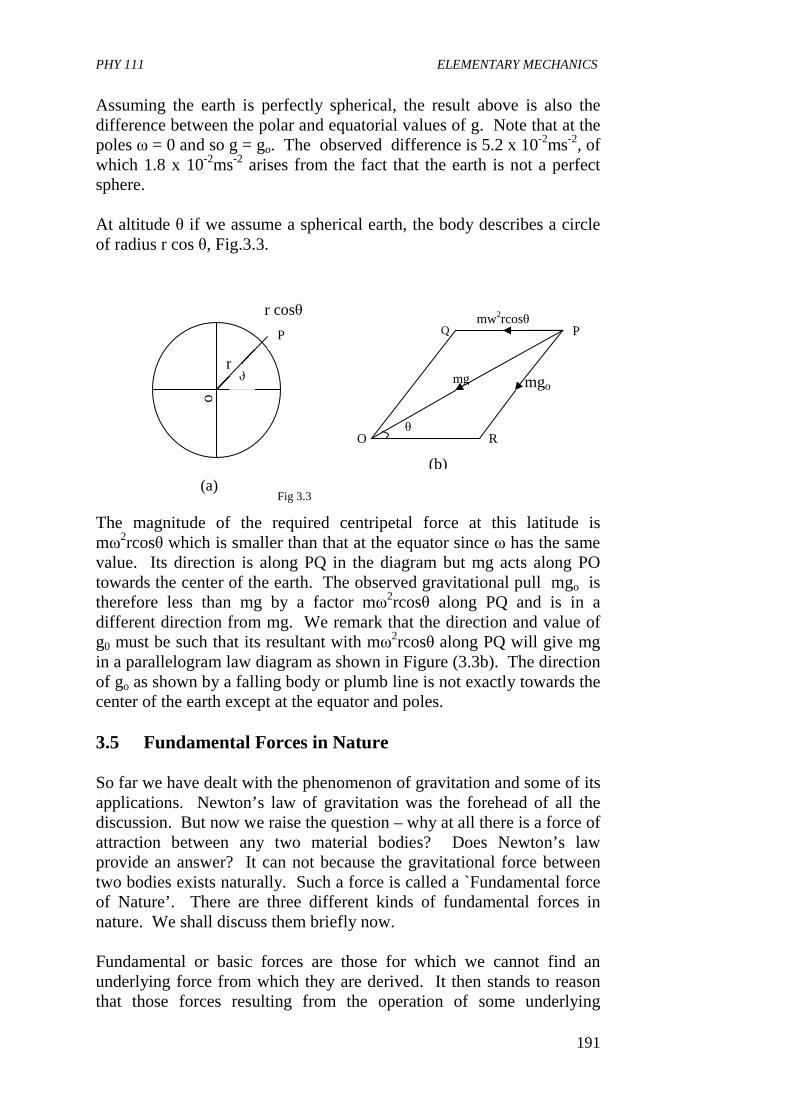
PHY 111 ELEMENTARY MECHANICS
191
Assuming the earth is perfectly spherical, the result above is also the difference between the polar and equatorial values of g. Note that at the poles ω = 0 and so g = go. The observed difference is 5.2 x 10⁻²ms-2, of which 1.8 x 10⁻²ms-2 arises from the fact that the earth is not a perfect sphere. At altitude θ if we assume a spherical earth, the body describes a circle of radius r cos θ, Fig.3.3. The magnitude of the required centripetal force at this latitude is mω2rcosθ which is smaller than that at the equator since ω has the same value. Its direction is along PQ in the diagram but mg acts along PO towards the center of the earth. The observed gravitational pull mgo is therefore less than mg by a factor mω2rcosθ along PQ and is in a different direction from mg. We remark that the direction and value of g0 must be such that its resultant with mω2rcosθ along PQ will give mg in a parallelogram law diagram as shown in Figure (3.3b). The direction of go as shown by a falling body or plumb line is not exactly towards the center of the earth except at the equator and poles. 3.5 Fundamental Forces in Nature
So far we have dealt with the phenomenon of gravitation and some of its applications. Newton’s law of gravitation was the forehead of all the discussion. But now we raise the question – why at all there is a force of attraction between any two material bodies? Does Newton’s law provide an answer? It can not because the gravitational force between two bodies exists naturally. Such a force is called a `Fundamental force of Nature’. There are three different kinds of fundamental forces in nature. We shall discuss them briefly now. Fundamental or basic forces are those for which we cannot find an underlying force from which they are derived. It then stands to reason that those forces resulting from the operation of some underlying
o
θ r
P
r cosθ
(a) Fig 3.3
Q
O θ
R
mgo
P mw2rcosθ
mg
(b)
PHY 111 ELEMENTARY MECHANICS
192
fundamental force are known as derived forces. This concept is similar to the concept of fundamental and derived units of measurement which we discussed in Unit 2 of this course. There are three kinds of fundamental forces. These are (i) gravitational (ii) electroweak and (iii) strong. You have read in detail in Units 11, 12 and this present one about gravitational force, which acts on all matter as you have seen so far. You recall that it varies inversely as the square of the distance but its range is infinite. This force is responsible for holding together the planets and stars and in fact, in overall organization of solar system and galaxies. The electro weak force includes electro-magnetism and the so called weak nuclear force. Electromagnetic forces include the force between two charged particles at relative rest (electrostatics) or in relative motion (electro-dynamics). The electrostatic between two charges obeys the inverse square law like gravitational force between two masses. [You will learn more about that in your electro magnetism course in the second semester]. The dissimilarity here is that charges are of two kinds – positive and negative. If the charges are of opposite kind the force between them is attractive but if they are of the same kind, the force is repulsive. It can be shown that the gravitational force between an electron and a portion in a hydrogen atom is 1039 times weaker than the electrostatic force between them. Thus we get a comparative estimate of the strengths of gravitational and electrostatic force. In the case of moving charges, we know that charges in motion give rise to electric current. You also learnt in the secondary school that a current carrying conductor is equivalent to a magnet. This is the meeting point of electricity and magnetism and hence the word `electromagnetic’ got associated with this field of force. The force that one comes across in daily life, like friction, tension etc. can be explained from the standpoint of the electromagnetic force field. An estimate of the relative strengths of the repulsive electrostatic and the attractive gravitational force between two protons in a nucleus shows that the former is 1036 times larger than the latter. So, how is it that the protons in an atomic nucleus, stay together instead of flying away? The answer lies in the third kind of fundamental force known as the strong (nuclear) force that exists between the protons inside the nucleus, which is strongly attractive, much stronger than the electrostatic force between them. Strong nuclear force also exists between neutrons in the nucleus as well as between neutrons and protons. The nuclear force decrease rapidly with distance so it is a short range force. You will study in detail about the nuclear forces in a nuclear physics course.
PHY 111 ELEMENTARY MECHANICS
193
The nuclear force as we have seen accounts for the binding of atomic nuclei. But this cannot account for processes like radioactivity beta decay about which, once again, you will read in the Nuclear Physics course. This can be explained from the point of view of the so-called weak nuclear force. It is much weaker than the electromagnetic force at nuclear distance but still greater by a factor of 1034 than the gravitational force. Just a few years ago, this weak force was listed separately from the electromagnetic force. However, a theory was proposed which led to the unification of the weak forces and the electromagnetic forces and hence the name `electroweak’ forces. 4.0 CONCLUSION In this unit, you have learnt • that the potential energy of a system of two point masses
interacting with each other through the gravitational force is rGmMU r /)( −= .
• That escape sped I e speed an object can have in order to escape from the surface of the earth into space
• tat the acceleration due to gravity, a decreases the farther away an object is far away from the center of the earth outside the earth’s surface.
• tat there is no gravitational field inside the shell beneath the earth’s surface if the shell is of uniform density.
• That g decreases linearly with depth below the earth’s surface, • That the acceleration due to gravity g increases with latitude. • That fundamental forces or basic forces are forces for which we
cannot find underlying forces from which they are derived. • That gravitational force is one of the fundamental forces in
nature. Others are electro weak and strong nuclear forces.
5.0 SUMMARY What you have learnt in this Unit are.
• That drrFUrUr
)()()( ∫ ∞=∞−
where U(r) – U(∞) is the potential energy of a system of two point masses interacting with each other. If U(∞) = O then
r
GmMrU −=)(
• That the escape speed or escape velocity is the minimum velocity needed by an object to be projected into space from the surface of the earth.
• That the potential energy gained by the satellite is equal to the kinetic energy lost (neglecting air resistance). Therefore from
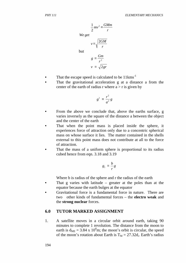
PHY 111 ELEMENTARY MECHANICS
194
r
GMv
getWer
GMmmv
2
2
1 2
=
=
but
grv
r
Gmg
2
2
=
=
• That the escape speed is calculated to be 11kms-1 • That the gravitational acceleration g at a distance a from the
center of the earth of radius r where a > r is given by
ga
rg
2
21 =
• From the above we conclude that, above the earths surface, g
varies inversely as the square of the distance a between the object and the center of the earth
• That when the point mass is placed inside the sphere, it experiences force of attraction only due to a concentric spherical mass on whose surface it lies. The matter contained in the shells external to this point mass does not contribute at all to the force of attraction.
• That the mass of a uniform sphere is proportional to its radius cubed hence from eqn. 3.18 and 3.19
gr
bg =1
Where b is radius of the sphere and r the radius of the earth
• That g varies with latitude – greater at the poles than at the equator because the earth bulges at the equator
• Gravitational force is a fundamental force in nature. There are two other kinds of fundamental forces – the electro weak and the strong nuclear forces.
6.0 TUTOR MARKED ASSIGNMENT 1. A satellite moves in a circular orbit around earth, taking 90
minutes to complete 1 revolution. The distance from the moon to earth is dME = 3.84 x 10⁸m; the moon’s orbit is circular, the speed of the moon’s rotation about Earth is TM = 27.32d. Earth’s radius
PHY 111 ELEMENTARY MECHANICS
195
is RE = 6.37 x 10⁶ m and Earth’s gravitational force acts as if all of Earth’s mass were concentrated at its center. With this information, calculate the height of the satellite above Earth.
2. By what percentage of its value at sea-level does g increase or decrease when one gets to (i) an altitude of 2500km and (ii) Kolar Gold Field at a depth of 3000m.
7.0 REFERENCES AND FURTHER READING Sears, F.W., Zemansky M.W and Young H.D (1975)College Physics 4th
Ed Addison – Wesley Publ. Lo, Reading U.K. Fishbane , P.M., Gasiorowicz, S. and Thronton S.T, (1996) Physics for
Scientists and Engineers, 2nd Ed. Prentice Hall.New Jersey. Nelkon M and Parker P (1970) Advanced Level Physics, Heinemann
Educational Books Ltd. London. Duncan T. (1982) phsics A Textbook for Advanced Level Students John
Munay (Publishers) Ltd. London.
PHY 111 ELEMENTARY MECHANICS
196
UNIT 4 FRICTION CONTENTS 1.0 Introduction 2.0 Objectives 3.0 Main Body
3.1 Laws of Friction 3.2 Nature of Friction
4.0 Conclusion 5.0 Summary 6.0 Tutor Marked Assignment 7.0 References and Further Reading 1.0 INTRODUCTION In Units 1, 5, 6 and 7 we saw that every object stays in relative rest or motion unless it is impinged upon by an applied force. In this unit we shall discuss friction. Friction is a type of force we experience everyday without giving it a thought. Have you ever considered why you walk without slipping unless you unknowingly step on a banana peel or on smooth slippery floor or on a thin film of water on a smooth film? We do not slip and fall down when we walk because of the frictional forces acting between our feet and the ground. Friction allows cars to move on the roads without skidding and it even holds nails and screws in place etc. The study of friction, wear and lubrication is called tribology and it is very important to industry. In studying frictional forces, you will draw from your knowledge of conditions for equilibrium of forces treated in Units 3 and 7. We shall limit our discussion in this course to solid friction. Friction also exists in liquids and gases but you will learn about that in your course on Thermal Physics and Properties of Matter next semester.
2.0 OBJECTIVES By the end of this Unit, you should be able to • describe an experiment to determine the coefficient of static or
dynamic friction • state where frictional forces act • define the coefficients of static and kinetic friction • state the laws of friction • apply the laws of friction in solving problems • differentiate between static and dynamic friction • explain the nature of friction
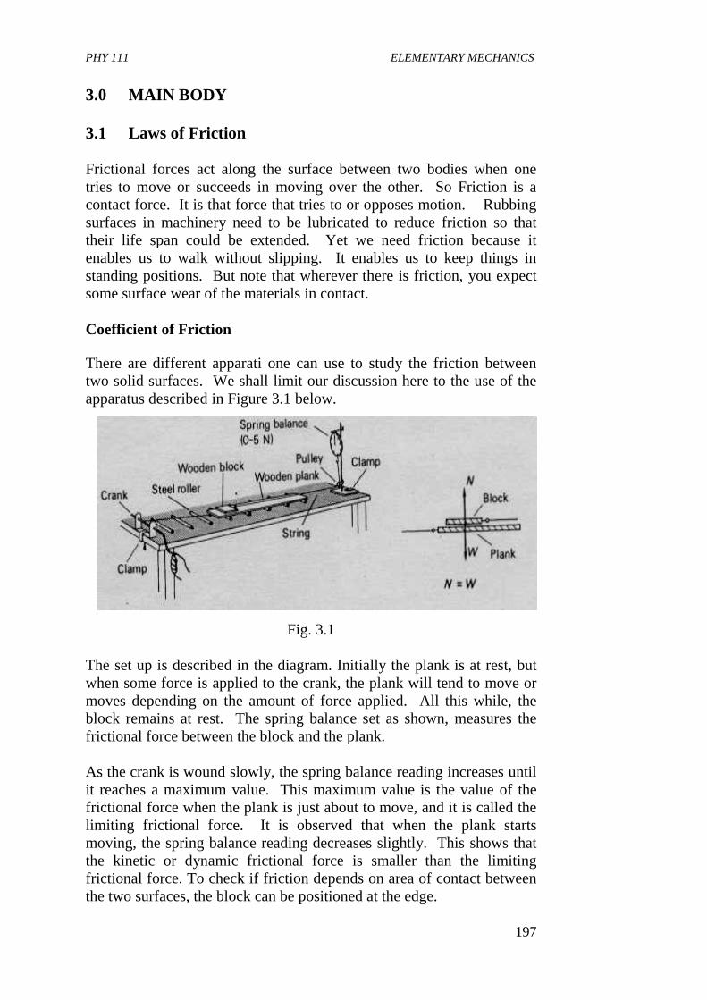
PHY 111 ELEMENTARY MECHANICS
197
3.0 MAIN BODY 3.1 Laws of Friction Frictional forces act along the surface between two bodies when one tries to move or succeeds in moving over the other. So Friction is a contact force. It is that force that tries to or opposes motion. Rubbing surfaces in machinery need to be lubricated to reduce friction so that their life span could be extended. Yet we need friction because it enables us to walk without slipping. It enables us to keep things in standing positions. But note that wherever there is friction, you expect some surface wear of the materials in contact. Coefficient of Friction There are different apparati one can use to study the friction between two solid surfaces. We shall limit our discussion here to the use of the apparatus described in Figure 3.1 below.
Fig. 3.1 The set up is described in the diagram. Initially the plank is at rest, but when some force is applied to the crank, the plank will tend to move or moves depending on the amount of force applied. All this while, the block remains at rest. The spring balance set as shown, measures the frictional force between the block and the plank. As the crank is wound slowly, the spring balance reading increases until it reaches a maximum value. This maximum value is the value of the frictional force when the plank is just about to move, and it is called the limiting frictional force. It is observed that when the plank starts moving, the spring balance reading decreases slightly. This shows that the kinetic or dynamic frictional force is smaller than the limiting frictional force. To check if friction depends on area of contact between the two surfaces, the block can be positioned at the edge.
PHY 111 ELEMENTARY MECHANICS
198
The normal force N exerted by the plank on the block is equal to the weight w of the block. So we can then vary the weight of the block by putting standard weights on it, and recording the corresponding frictional forces as indicated by the spring balance. Thus the effect of frictional force of varying N can be found. The results of such an experiment are summarized in what we call the laws of friction which state that: 1. The frictional force between two surface opposes their relative
motion. 2. The frictional force does not depend on the area of contact of the
surfaces 3(a) When the forces are at rest the limiting frictional force F is
directly proportional to the normal force N (b) When motion occurs the kinetic (dynamic) frictional force F is
directly proportional to the normal force N i.e. FR α N (or FR/N = constant) and is reasonably independent of the relative velocity of the surfaces.
Hence the coefficient of limiting static friction µs is
1.3tconataN
Fs ηµ ==
and that coefficient of kinetic (dynamic) friction is
2.3tConstaN
FKK ηµ ==
Note that for two given surfaces, µk is less than µs, though occasionally they may be assumed to be equal. For sliding over wood, µ is about 0.2 to 0.5. Generally, when a surface exerts a frictional force the resultant force in a body on the surface has two components. It has a normal force N which is perpendicular to the surface and a frictional force F along the surface with direction opposite to the direction and motion. This is illustrated in Figure (3.2) below F
N
Body moving to the right Resultant force
Fig 3.2
PHY 111 ELEMENTARY MECHANICS
199
Note that if the surface is smooth, then µ = 0 and so F = 0. We conclude then that a smooth surface will only exert a force at right angles to itself, that is, only the normal force survives here. Can you think of any other way by which we can find the coefficient of limiting friction? Yes. Another possible way is by placing a block of mass m on the surface of say a horizontal plank and tilting the plank gradually. The angle of tilt is slowly increased until the block is just about to slip as shown in Figure 3.3a. The forces acting on the block are (i) its weight mg (ii) the normal force N of the surface and (iii) the limiting frictional force F – µN. These three forces are in equilibrium. Let mg be the weight of mass m. When mg is resolved into its components, we might get mgcosθ along the surface and mgcosθ perpendicular to the surface as shown in Fig 3.3b. Then we have that
F = µN = mg sinθ 3.3 N = mgcosθ 3.4 Dividing and Eqn. (3.3) by (3.4) gives
µ = tan θ 3.5
Thus if we measure angle θ, then µ can be computed.
(a)
θ
F
N
Mg
θ
F
N
(b) mg cosθ
mg sinθ
θ
PHY 111 ELEMENTARY MECHANICS
200
Example A uniform ladder 4.0m long, of mass 25kg, rests with its upper end against a smooth vertical wall and with its lower end on rough ground. What must be the least coefficient of friction between the ground and the ladder for it to be inclined at 60° with the horizontal without slipping? Solution Mg = wt. of ladder = 250N The forces acting are as shown in the diagram. The wall is smooth so the force S is normal to it. We assume the weight of the ladder to be acting from the mid point G because it is of uniform cross section. When the ladder is just about to slip, the force exerted on it by the ground could be resolved into its vertical (normal and horizontal components i.e. its normal force N and its limiting frictional forces Fs = µsN correspondingly. Now µs is the expected coefficient of limiting friction, we are to find. So, for equilibrium W = 250 Newtons = N for vertical forces and FS = µSN = S for horizontal components If we now take moments about point A then,
NewtonsS
Newtons
SinxxS
ADxWACxSoo
3
125
250
30225030cos0.4
=∴
==
=
Hence,
29.03250
125
=
==
S
sN
S
µ
µ
Fig 3.4
A
4m
G
B S
C
N
FS D
W 600
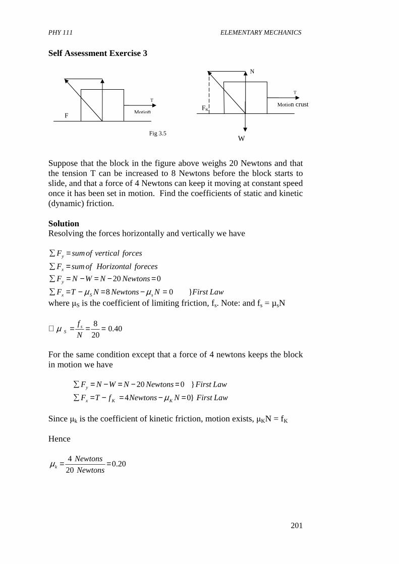
PHY 111 ELEMENTARY MECHANICS
201
Self Assessment Exercise 3 Suppose that the block in the figure above weighs 20 Newtons and that the tension T can be increased to 8 Newtons before the block starts to slide, and that a force of 4 Newtons can keep it moving at constant speed once it has been set in motion. Find the coefficients of static and kinetic (dynamic) friction.
Solution Resolving the forces horizontally and vertically we have
LawFirstNNewtonsNTF
NewtonsNWNF
forecesHorizontalofsumF
forcesverticalofsumF
sSx
y
x
y
}08
020
=−=−=∑
=−=−=∑
=∑
=∑
µµ
where µS is the coefficient of limiting friction, fs. Note: and fs = µsN
40.020
8 ===∴N
f sSµ
For the same condition except that a force of 4 newtons keeps the block in motion we have
LawFirstNNewtonsfTF
LawFirstNewtonsNWNF
KKx
y
}04
}020
=−=−=∑
=−=−=∑
µ
Since µk is the coefficient of kinetic friction, motion exists, µKN = fK Hence
20.020
4 ==Newtons
Newtonskµ
F
T
Motion
Fig 3.5
N
T
W
FK Motion crust
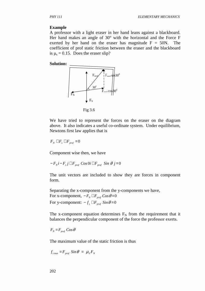
PHY 111 ELEMENTARY MECHANICS
202
Example A professor with a light eraser in her hand leans against a blackboard. Her hand makes an angle of 30° with the horizontal and the Force F exerted by her hand on the eraser has magnitude F = 50N. The coefficient of prof static friction between the eraser and the blackboard is µs = 0.15. Does the eraser slip? Solution: We have tried to represent the forces on the eraser on the diagram above. It also indicates a useful co-ordinate system. Under equilibrium, Newtons first law applies that is
0=++ profsN FFF
Component wise then, we have
00 =++−− jSinFiCosFjFiF profprofsN θ
The unit vectors are included to show they are forces in component form. Separating the x-component from the y-components we have, For x-component, 0=+− θCosFF profN
For y-component: 0=+− θSinFf profs
The x-component equation determines FN from the requirement that it balances the perpendicular component of the force the professor exerts.
θCosFF profN =
The maximum value of the static friction is thus
NSprofs FSinFf µθ ==max
FS
FN Fprof cos300
Fprof sin300 Fprof
300
Fig 3.6
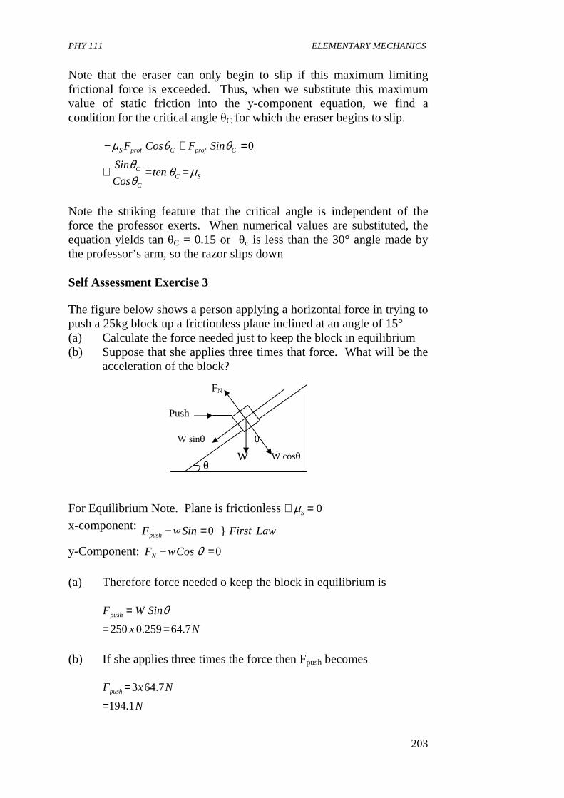
PHY 111 ELEMENTARY MECHANICS
203
Note that the eraser can only begin to slip if this maximum limiting frictional force is exceeded. Thus, when we substitute this maximum value of static friction into the y-component equation, we find a condition for the critical angle θC for which the eraser begins to slip.
SC
C
C
CprofCprofS
tenCos
Sin
SinFCosF
µθθθ
θθµ
==∴
=+− 0
Note the striking feature that the critical angle is independent of the force the professor exerts. When numerical values are substituted, the equation yields tan θC = 0.15 or θc is less than the 30° angle made by the professor’s arm, so the razor slips down Self Assessment Exercise 3 The figure below shows a person applying a horizontal force in trying to push a 25kg block up a frictionless plane inclined at an angle of 15° (a) Calculate the force needed just to keep the block in equilibrium (b) Suppose that she applies three times that force. What will be the
acceleration of the block?
For Equilibrium Note. Plane is frictionless 0=∴ Sµ
x-component: LawFirstSinwFpush }0=−
y-Component: 0=− θCoswFN
(a) Therefore force needed o keep the block in equilibrium is
Nx
SinWFpush
7.64259.0250 ==
= θ
(b) If she applies three times the force then Fpush becomes
N
NxFpush
1.194
7.643
=
=
FN
W
W sinθ
Push
W cosθ
θ
θ
PHY 111 ELEMENTARY MECHANICS
204
But the weight of the block acting in the negative x axis is w Sinθ Fnet for push is 194.1 – 64.7 = 129.4N But Fnet I = m x a Where Fnet is the net or effective force pushing up the black
217.5
25
4.129
−=
==∴
msa
kg
N
m
Fa net
3.2 Nature of Friction The coefficients of static and kinetic (dynamic or sliding) friction depend on the nature of surfaces in contact between two bodies. Coefficient of friction is large for rough surfaces than for smooth ones. The coefficient of kinetic friction varies with the relative velocity but for the sake of simplicity we assume it to be independent of velocity. Close examination of the flattest and most polished surfaces reveals that there still exist hollows and humps which are more than one hundred atoms stacked one on top of the other. This means that when two solid surfaces are placed one on the other, or are made to touch, their actual area of contact is very small. An example is shown in Figure 3.7 below Electrical resistance measurements of two metals in contact reveal that the true area of contact between the surfaces is extremely very small. It is estimated that in the case of steel, the actual area that is touching many be just about one ten thousandth (1/10,000th) of the apparent area actually placed together. Two metal surfaces thus sit on each other’s projections when they are placed one on top of the other. This goes for non-metallic objects too. Look around your room where you are now and examine surfaces in contact with each other. But note that you can not see all we are saying with the naked eyes. Yet, the concept of frictional force is easy to experience when you try to push or pull a heavy table.
Fig 3.7
PHY 111 ELEMENTARY MECHANICS
205
Pressures at the points of contact between two metals are extremely high and cause the bumps to flatten until the increased area of content enables the upper solid to be supported. It is presumed that at the point of contact small, cold welded joints’ are formed by the strong adhesive forces between molecules that are very close together. These have to be broken before one surface can slide over the other. This phenomenon accounts for the first law of frictional force. Experiments like the ones made by Leonardo da Vinci some 200 years before Newton’s work on dynamics (Fishbane et al) with a set of blocks of varying sizes sliding on table tops show that changing the apparent area of contact of the bodies has little effect on the actual area for the same normal force. This explains the second law of friction. It is also found that the actual area is proportional to the normal force and since this theory suggests that frictional force depends on the actual area, we might expect the frictional force to be proportional to the normal force – as the third law states. 4.0 CONCLUSION In this unit, you have learnt • that friction is a contact force which acts along the surface
between two bodies in contact when one tries to move or succeeds in moving.
• that friction opposes motion • that the coefficient of friction is the maximum limiting force just
before a body starts sliding over another surface. • the three laws of friction. • how to apply the laws of friction to solve relevant problems
pertaining to friction. • about the nature of friction.
5.0 SUMMARY What you have learnt in this unit concerns frictional force. You have learnt • what frictional force is • where it acts • how it is determined • the laws of frictional force • to differentiate between static and dynamic friction • how to apply the laws of friction in solving problems • the nature of friction that
N
F
N
F Kk
SS == µµ ;
PHY 111 ELEMENTARY MECHANICS
206
where the symbols have their usual meaning • that friction is important to life because it allows us to walk, drive
cars etc. and place things in steady positions, etc. • that friction between two surfaces in contact leads to wearing off
of such surfaces hence such matter needs lubrication. • that since friction is important in the industry it is essential that
we study about it.
6.0 TUTOR MARKED ASSIGNMENT (TMA) 1. An automobile with four wheel drive and a powerful engine has a
mass of 1000kg. Its weight is evenly distributed on its four wheels whose coefficient of static friction with dry road is µS = 0.8. If the car starts from rest on a horizontal surface, what is the greatest forward acceleration that it can attain without spinning its wheels?
2. What is the friction force if the block weighing w = 20N in the
figure above is at rest on the surface and a horizontal force of 5N is exerted on it.
3. What force T at an angle of 30° above the horizontal is required
to drag a block weighing 20N to the right at constant speed, if the coefficient of kinetic friction between block and surface is 0.20?
4. Two blocks of masses M and m are connected by a light rope
which passes over a frictionless pulley. Mass M sits on an inclined plane with an angle of inclination of 30°. The coefficient of static friction between mass M and the inclined plane is 0.20, while m = 30kg. Determine the smallest and largest possible values of M for which the system remains in equilibrium.
7.0 REFERENCES AND FURTHER READING Sears, F.W., Zemansky M.W and Young H.D (1975) College Physics
(4th Ed) Addison – Wesley Publ. co, Reading U.K. Fishbane , P.M., Gasiorowicz, S. and Thronton S.T, (1996) Physics for
Scientists and Engineers, 2nd Ed. Prentice Hall, New Jersey. Nelkon M and Parker P (1970) Advanced Level Physics, Heinemann
Educational Books Ltd. London. Duncan T. (1982)Physics A Textbook for Advanced Level Students,
John Munay (Publishers) Ltd. London.
PHY 111 ELEMENTARY MECHANICS
207
UNIT 5 WORK AND ENERGY CONTENTS 1.0 Introduction 2.0 Objectives 3.0 Main Body
3.1 Work 3.1.1 Work done by a Constant Force 3.1.2 Unit of Work 3.1.3 Work done by a Varying Force
3.2 Energy 3.2.1 Kinetic Energy 3.2.2 Potential Energy 3.2.3 Conservation of Energy
4.0 Conclusion 5.0 Summary 6.0 Tutor Marked Assignment (TMA) 7.0 References and Further Reading 1.0 INTRODUCTION Work and energy is central to life. We do it and experience it every day. We can thus say that the notion of energy is one of the most basic concepts in physics and indeed in all sciences. Energy takes many forms and in this unit we shall focus on energy contained in moving objects which we call kinetic energy and also in energy a body possesses by virtue of its position called potential energy. The work done on an object involves the force acting on it as it moves. We can relate the change in kinetic energy of an object to the work done on it as it moves. This relation is called work-energy theorem. In this unit you will learn how to calculate the work done by an object which will serve as a powerful tool for the understanding of motion.
2.0 OBJECTIVES By the end of this unit, you should be able to: • define work in the scientific sense • distinguish between positive and negative work • determine the work done by a varying force • explain the terms energy, potential and kinetic energy • state the principle of conservation of mechanical energy • apply the work-energy equation in solving energy related
problems. • state the fundamental law of conservation of energy
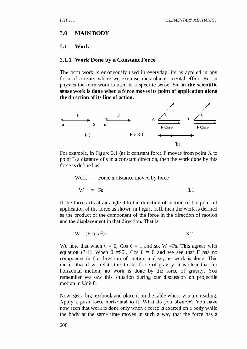
PHY 111 ELEMENTARY MECHANICS
208
3.0 MAIN BODY 3.1 Work 3.1.1 Work Done by a Constant Force The term work is erroneously used in everyday life as applied in any form of activity where we exercise muscular or mental effort. But in physics the term work is used in a specific sense. So, in the scientific sense work is done when a force moves its point of application along the direction of its line of action.
For example, in Figure 3.1 (a) if constant force F moves from point A to point B a distance of s in a constant direction, then the work done by this force is defined as
Work = Force x distance moved by force W = Fs 3.1
If the force acts at an angle θ to the direction of motion of the point of application of the force as shown in Figure 3.1b then the work is defined as the product of the component of the force in the direction of motion and the displacement in that direction. That is W = (F cos θ)s 3.2 We note that when θ = 0, Cos θ = 1 and so, W =Fs. This agrees with equation (3.1). When θ =90o, Cos θ = 0 and we see that F has no component in the direction of motion and so, no work is done. This means that if we relate this to the force of gravity, it is clear that for horizontal motion, no work is done by the force of gravity. You remember we saw this situation during our discussion on projectile motion in Unit 8. Now, get a big textbook and place it on the table where you are reading. Apply a push force horizontal to it. What do you observe? You have now seen that work is done only when a force is exerted on a body while the body at the same time moves in such a way that the force has a
S
F Cosθ
A θ
F Cosθ
B θ
(b)
B F
A S
F
(a) Fig 3.1
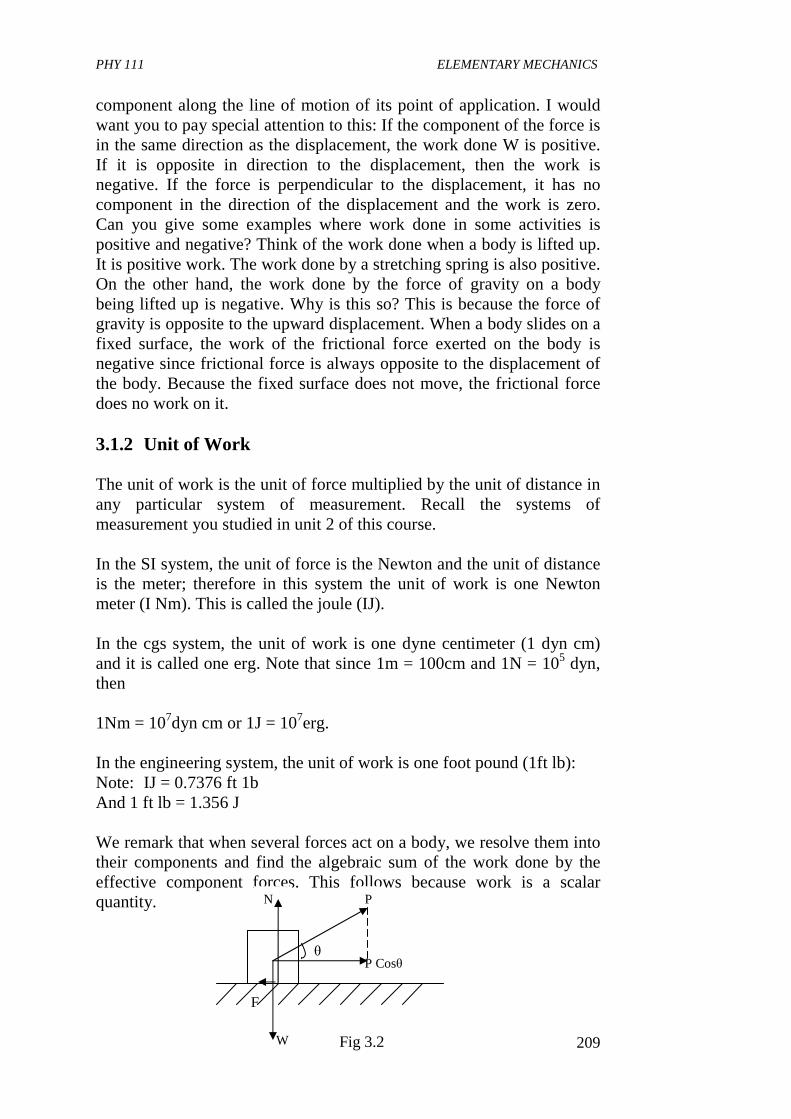
PHY 111 ELEMENTARY MECHANICS
209
component along the line of motion of its point of application. I would want you to pay special attention to this: If the component of the force is in the same direction as the displacement, the work done W is positive. If it is opposite in direction to the displacement, then the work is negative. If the force is perpendicular to the displacement, it has no component in the direction of the displacement and the work is zero. Can you give some examples where work done in some activities is positive and negative? Think of the work done when a body is lifted up. It is positive work. The work done by a stretching spring is also positive. On the other hand, the work done by the force of gravity on a body being lifted up is negative. Why is this so? This is because the force of gravity is opposite to the upward displacement. When a body slides on a fixed surface, the work of the frictional force exerted on the body is negative since frictional force is always opposite to the displacement of the body. Because the fixed surface does not move, the frictional force does no work on it. 3.1.2 Unit of Work
The unit of work is the unit of force multiplied by the unit of distance in any particular system of measurement. Recall the systems of measurement you studied in unit 2 of this course. In the SI system, the unit of force is the Newton and the unit of distance is the meter; therefore in this system the unit of work is one Newton meter (I Nm). This is called the joule (IJ). In the cgs system, the unit of work is one dyne centimeter (1 dyn cm) and it is called one erg. Note that since 1m = 100cm and 1N = 105 dyn, then 1Nm = 107dyn cm or 1J = 107erg. In the engineering system, the unit of work is one foot pound (1ft lb): Note: IJ = 0.7376 ft 1b And 1 ft lb = 1.356 J We remark that when several forces act on a body, we resolve them into their components and find the algebraic sum of the work done by the effective component forces. This follows because work is a scalar quantity.
N
F
W
P Cosθ
P
θ
Fig 3.2
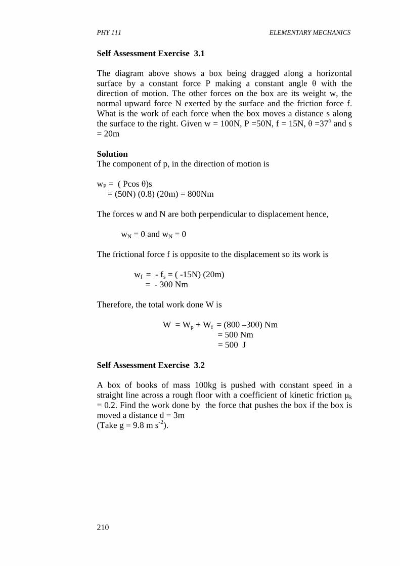
PHY 111 ELEMENTARY MECHANICS
210
Self Assessment Exercise 3.1 The diagram above shows a box being dragged along a horizontal surface by a constant force P making a constant angle θ with the direction of motion. The other forces on the box are its weight w, the normal upward force N exerted by the surface and the friction force f. What is the work of each force when the box moves a distance s along the surface to the right. Given w = 100N, P =50N, f = 15N, θ =37o and s = 20m Solution The component of p, in the direction of motion is wP = ( Pcos θ)s = (50N) (0.8) (20m) = 800Nm The forces w and N are both perpendicular to displacement hence,
wN = 0 and wN = 0
The frictional force f is opposite to the displacement so its work is
wf = - fs = ( -15N) (20m) = - 300 Nm Therefore, the total work done W is
W = Wp + Wf = (800 –300) Nm = 500 Nm = 500 J Self Assessment Exercise 3.2 A box of books of mass 100kg is pushed with constant speed in a straight line across a rough floor with a coefficient of kinetic friction µk = 0.2. Find the work done by the force that pushes the box if the box is moved a distance d = 3m (Take g = 9.8 m s-2).
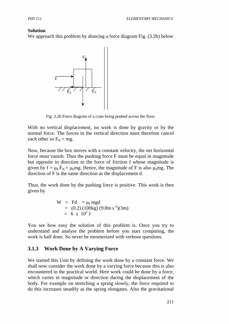
PHY 111 ELEMENTARY MECHANICS
211
Solution We approach this problem by drawing a force diagram Fig. (3.2b) below
Fig .3.2b Force diagram of a crate being pushed across the floor. With no vertical displacement, no work is done by gravity or by the normal force. The forces in the vertical direction must therefore cancel each other so FN = mg. Now, because the box moves with a constant velocity, the net horizontal force must vanish. Thus the pushing force F must be equal in magnitude but opposite in direction to the force of friction f whose magnitude is given by f = µk FN = µkmg. Hence, the magnitude of F is also µkmg. The direction of F is the same direction as the displacement d. Thus, the work done by the pushing force is positive. This work is then given by
W = Fd = µk mgd
= (0.2) (100kg) (9.8m s-2)(3m) = 6 x 10² J You see how easy the solution of this problem is. Once you try to understand and analyse the problem before you start computing, the work is half done. So never be mesmerized with verbose questions. 3.1.3 Work Done by A Varying Force
We started this Unit by defining the work done by a constant force. We shall now consider the work done by a varying force because this is also encountered in the practical world. Here work could be done by a force, which varies in magnitude or direction during the displacement of the body. For example on stretching a spring slowly, the force required to do this increases steadily as the spring elongates. Also the gravitational
F
UK
FN
FK
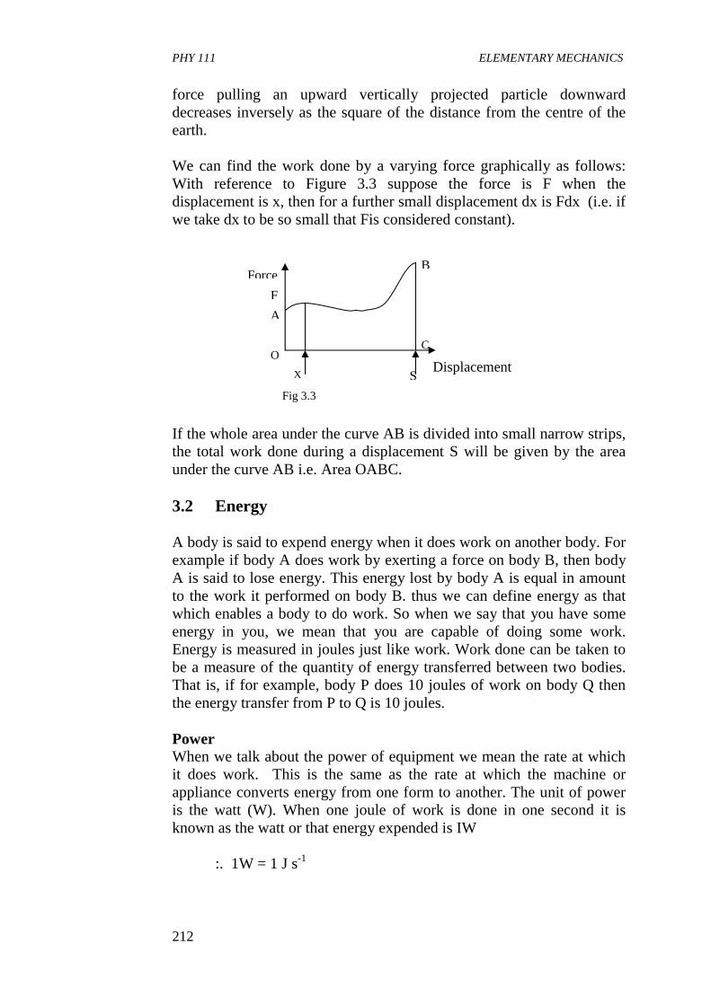
PHY 111 ELEMENTARY MECHANICS
212
force pulling an upward vertically projected particle downward decreases inversely as the square of the distance from the centre of the earth. We can find the work done by a varying force graphically as follows: With reference to Figure 3.3 suppose the force is F when the displacement is x, then for a further small displacement dx is Fdx (i.e. if we take dx to be so small that Fis considered constant). If the whole area under the curve AB is divided into small narrow strips, the total work done during a displacement S will be given by the area under the curve AB i.e. Area OABC. 3.2 Energy A body is said to expend energy when it does work on another body. For example if body A does work by exerting a force on body B, then body A is said to lose energy. This energy lost by body A is equal in amount to the work it performed on body B. thus we can define energy as that which enables a body to do work. So when we say that you have some energy in you, we mean that you are capable of doing some work. Energy is measured in joules just like work. Work done can be taken to be a measure of the quantity of energy transferred between two bodies. That is, if for example, body P does 10 joules of work on body Q then the energy transfer from P to Q is 10 joules.
Power When we talk about the power of equipment we mean the rate at which it does work. This is the same as the rate at which the machine or appliance converts energy from one form to another. The unit of power is the watt (W). When one joule of work is done in one second it is known as the watt or that energy expended is IW
:. 1W = 1 J s-1
B
C
S X
O
F
A
Force
Displacement
Fig 3.3
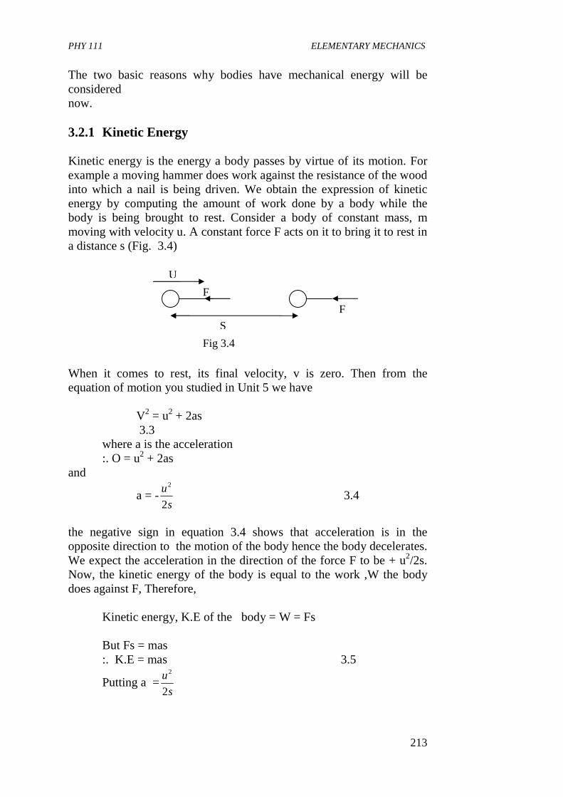
PHY 111 ELEMENTARY MECHANICS
213
The two basic reasons why bodies have mechanical energy will be considered now.
3.2.1 Kinetic Energy Kinetic energy is the energy a body passes by virtue of its motion. For example a moving hammer does work against the resistance of the wood into which a nail is being driven. We obtain the expression of kinetic energy by computing the amount of work done by a body while the body is being brought to rest. Consider a body of constant mass, m moving with velocity u. A constant force F acts on it to bring it to rest in a distance s (Fig. 3.4)
When it comes to rest, its final velocity, v is zero. Then from the equation of motion you studied in Unit 5 we have
V2 = u2 + 2as 3.3 where a is the acceleration
:. O = u2 + 2as and
a = -s
u
2
2
3.4
the negative sign in equation 3.4 shows that acceleration is in the opposite direction to the motion of the body hence the body decelerates. We expect the acceleration in the direction of the force F to be + u2/2s. Now, the kinetic energy of the body is equal to the work ,W the body does against F, Therefore, Kinetic energy, K.E of the body = W = Fs
But Fs = mas
:. K.E = mas 3.5
Putting a =s
u
2
2
F
S
F
U
Fig 3.4
PHY 111 ELEMENTARY MECHANICS
214
we have
K.E = 2
2
1mu 3.6
You now see how we derive the popular expression for K.E. Conversely if work is done on a body the gain of kinetic energy when its velocity
increases from zero to u can be shown also to be 22
1mu .
We now generalise. If a body of mass, m with an initial velocity of u moves when work is done on it by a force acting over a distance s and if its final velocity is v then the work done Fs is given by
Fs = 2
2
1mv - 2
2
1mu
3.7
Eqn. (3.7) is called the work- energy equation. It may be stated in words as follows: Work done by the forces (Acting on the body) = change in kinetic energy of the body. 3.2.2 Potential Energy The potential energy of a system of bodies is the energy the body has by virtue of the relative position of the parts of the body of the system. Potential energy P.E arises when a body experiences a force in a region or field. An example is the gravitational field of the earth. In this case, the body occupies a position with respect to the earth. The P.E is then taken to be a joint property of the body–earth system and not of either body separately. Thus the P.E is determined by the relative position of the body and the earth. It is seen that the greater the separation, the greater the P.E. The P.E of a body on the surface of the earth is always taken to be zero. But for a body of mass m at a height h above ground level, the P.E. is equal to the work that will be done against gravity, to raise the body to this height. This means that a force equal and opposite to mg is needed to be applied to the body to raise it to the required height. This is because we have assumed g to be constant near the surface of the earth. Hence ,
Work done by external force (against gravity) = Force x displacement
= mgh :. P.E = mgh 3.8
PHY 111 ELEMENTARY MECHANICS
215
When the body returns straight to the ground level an equal amount of potential energy is lost. Example: A car of mass 1x 10³ kg traveling at 72 km h-1 on a horizontal road is brought to rest in a distance of 40m by the action of the brakes and frictional forces. Find (a) the average stopping force (b) the time taken to stop the car. Solution: A speed of 72km h-1 = 72 x103m/3600s = 20ms-1 (a) If the car has mass m and initial speed u, then
K.E lost by car = ½ mu2 If F is the average stopping force and s the distance over which it acts, then Work done by car against F = Fs
But Fs = ½ mu2
:. F x 40m = ½ x (1 x10³kg) x (20ms-1)2
Nx
m
smky
x
xxF
3
23
100.5
2
402
00.4100.1
=
=−
(b) Assuming constant acceleration and substituting
v = 0, u =20m s-1 and s= 40m in v2 = u2 + 2as we have 0 = 202 + 2a x 40 :. a = -5.0 ms-2
the negative sign indicates the acceleration is in the opposite direction to the displacement. Using v = u +at we have 0 = 20 – 5. 0t :. t = 4.0s Self Assessment Exercise 3.3 What is the kinetic energy of a body of mass 10kg moving with an initial velocity V1 = 4m s-1 If the force applied to the body is 25N. What is its acceleration and final K.E if the body covered a distance of 20m The initial K.E = ½ MV,2 = ½ (10kg) (4ms-1)2
= 80J To find the final K.E we need to know the acceleration and final velocity. Hence
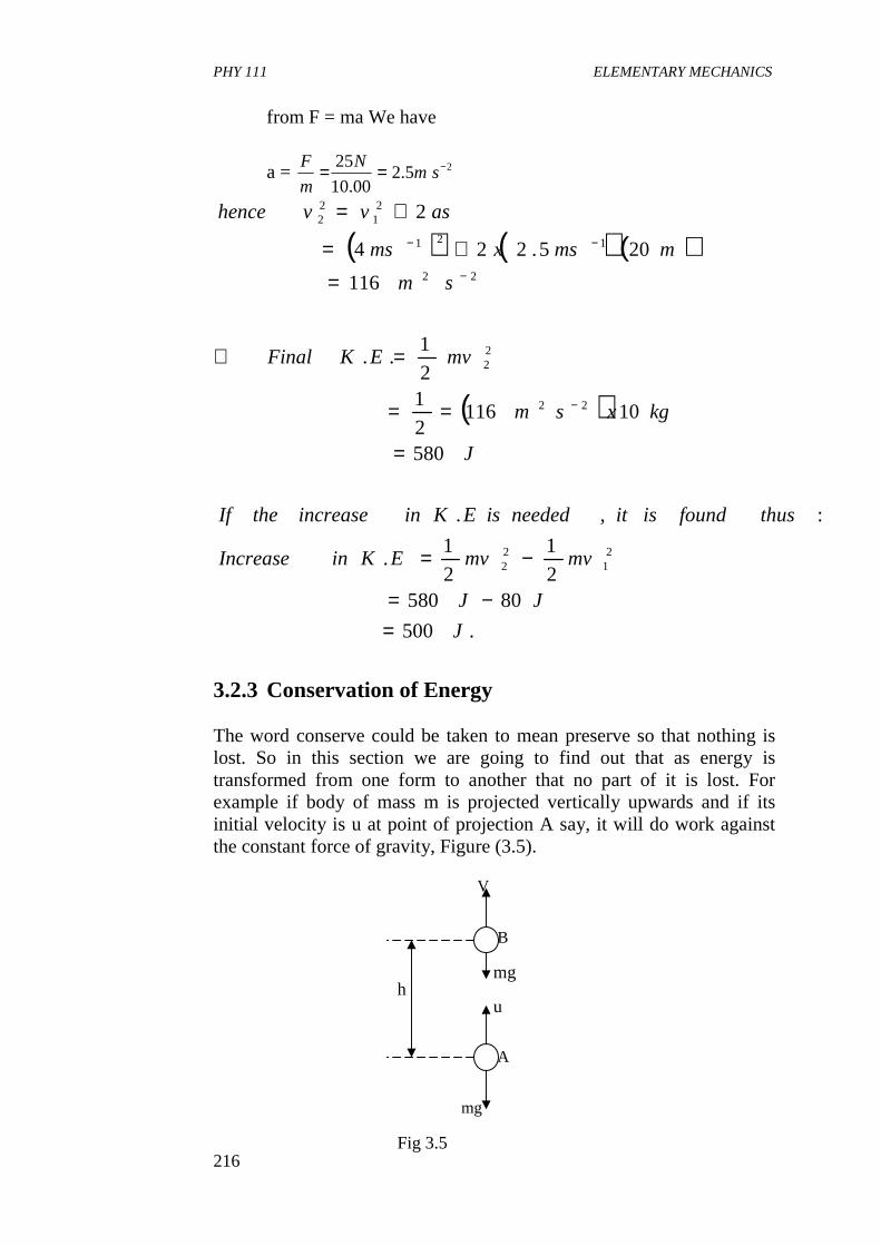
PHY 111 ELEMENTARY MECHANICS
216
from F = ma We have
a = 25.200.10
25 −== smN
m
F
( ) ( )( )
( )
.500
805802
1
2
1.
:,.
580
101162
12
1..
116
205.224
2
21
22
22
22
22
121
21
22
J
JJ
mvmvEKinIncrease
thusfoundisitneededisEKinincreasetheIf
J
kgxsm
mvEKFinal
sm
mmsxms
asvvhence
=−=
−=
=
==
=∴
=
+=
+=
−
−
−−
3.2.3 Conservation of Energy The word conserve could be taken to mean preserve so that nothing is lost. So in this section we are going to find out that as energy is transformed from one form to another that no part of it is lost. For example if body of mass m is projected vertically upwards and if its initial velocity is u at point of projection A say, it will do work against the constant force of gravity, Figure (3.5).
V
mg
A
B
mg
u h
Fig 3.5
PHY 111 ELEMENTARY MECHANICS
217
Let the velocity of body at a higher point B be V and the height attained at this point be h. Now, by definition K.E lost between points A and B = work done by body against mg Also by definition of P.E Gain of P.E between A and B = work done by the body against mg Therefore, we have that loss of K.E. = gain of P.E
:. ½ mu2 – ½ mv2 = mgh 3.9
This is what we call the principle of conservation of mechanical energy. This principle is stated as follows; the total amounts of mechanical energy (K.E + P.E) which the
bodies in an isolated system possess is constant. This applies only to frictionless motion i.e. to conservative system. Also, the gain in P.E will depend on the path taken but it does not in a conservative system. Note that work done against frictional forces is often accompanied by a temperature rise. Therefore in our energy account we have to take this into consideration. By so doing our energy conservation principles will be extended to include non- conservative systems and it becomes loss of K.E = gain of P.E + gain of internal energy. Thus the mechanics of a body in motion has been related to a phenomenon which is not clearly mechanical and in which motion is not directly detected. But we know that the internal energy is as a result of random molecular kinetic and potential energy of the particles of the system. In the same way energy has been extended to other parts of physics and it is now a unifying theme. Physics is at times referred to as the study of energy transformations, measured in terms of the workdone by forces created in the transformation. We thus see that the principle of conservation of mechanical energy is a special case of the more general principle of conservation of energy, which is one of the fundamental laws of science. Energy may be transformed from one form to another, but it cannot be created or destroyed, ie. The total energy of a system is constant.
PHY 111 ELEMENTARY MECHANICS
218
Self Assessment Exercise 3.4 Early in the nineteenth century, James Watt wanted to market his newly discovered steam engine to a society that until then had relied heavily on horses. So Watt invented a unit that made it clear how useful a steam engine could be. He conducted a demonstration in which a horse lifted water from a well over a certain period of time and called the corresponding power expended “one horse power”. Assume that water has a mass density of 1.0 x 10³kg/m3, the well was 20m deep, and the horse worked for 8 hours. How many litres of water did the horse raise from the well? Solution: Let the mass density of water be ρ. Then a volume V of water has mass, M = ρV. So, the work done in lifting a mass m of water from the bottom of the well is,
W = F∆Y = mg∆y
Where ∆y is the depth of the well. Thus the work done in lifting a volume V from the well in a time t is ρ Vg∆y and the power is
t
yVg
time
Workp
∆== ρ
We notice that the only unknown term here is volume V and we now solve for it:
yg
ptV
∆=
ρ
Since 1 horse power = 746W
( )( )( )( )( )
32
133
1
101.1
208.9100.1
36000.8746
mx
mmskgmx
shhxWV
=
= −−
−
but because there are 103L in Im3 the number of litres lifted by the horse is 1.1 x10⁵L.
PHY 111 ELEMENTARY MECHANICS
219
4.0 CONCLUSION In this unit you have leant • how work is defined in the scientific sense • to distinguish between positive and negative work depending on
the sign of the force, which does the work. • that the unit of work is the joule. • how to determine the work done by a varying force • the forms of energy and the principle of conservation of
mechanical energy • how to apply the work-energy equation in solving problems
related to energy.
5.0 SUMMARY What you have learnt in this unit concerns work and energy.
• that work is done when a force moves a distance in the direction
of the line of action of the force. Fs =W or (F cos θ) s =W
• that the unit of work is the joule, • that work done by a varying force could be represented
graphically and it is equal to the area under the curve of a force-displacement graph.
• that work is a measure of the quantity of energy transferred between two bodies.
• that power is the rate of doing work. • that energy could be in the form of kinetic energy → ½ mv2
Potential energy → mgh or internal energy due to molecular vibrations and P.E
• that the work-energy equation is given by Fs = ½ mv2 – ½ mu2
where the symbols have their usual meanings. • that the total amount of mechanical energy (K.E + P.E) which the
bodies of an isolated system possesses is constant. • that energy may be transformed from one form to the other but
can never be created or destroyed i.e. total energy of a system is always constant.
6.0 TUTOR MARKED ASSIGNMENT 1. A bullet of mass 10g traveling horizontally at a speed of 1.0x
102m s-1 embeds itself in a block of wood of mass 9.9 x10²g suspended by strings so that it can swing freely. Find (a) the vertical height through which the block rises (b) how much of the bullet’s energy becomes internal energy.
PHY 111 ELEMENTARY MECHANICS
220
(g = 10ms-2). 2 A car of mass 1200kg falls a vertical distance of 24m
starting from rest what is the work done by the force of gravity on the car? Use the work-energy theorem to find the final velocity of the car just before it hits the water. (Treat the car as a point like object).
3 A crate of mass 96kg is pushed across a horizontal floor by a force F. The coefficient of kinetic friction between the crate and the floor is µk = 0.27. The crate moves with uniform velocity. What is the magnitude of force F? Suppose that at some point the crate passes on to a new section of floor, where µk 0.085. The pushing force on the crate is unchanged. After 1.2m on the new section of the floor, the crate moves with a speed of vi = 2.3 m s-1. What was the original speed of the crate vi?
7.0 REFERENCES AND FURTHER READINGS Sears, F.W., Zemansky M.W and Young H.D (1975)College Physics
(4th Ed) Addison – Wesley Publ. Co, Reading U.K. Fishbane, P.M., Gasiorowicz, S. and Three S.T, (1996) Physics for
Scientists and Engineers, 2nd Ed. Prentice Hall, New Jersey. Nelkon M and Parker P (1970) Advanced Level PhysicsHeinemann
Educational Books Ltd. London. Duncan T.(1982) Physics, A Textbook for Advanced Level Students.
John Murray(Publishers) Ltd London
PHY 111 ELEMENTARY MECHANICS
221
Module 4 Unit 1: Simple Harmonic Motion I Unit 2: Simple Harmonic Motion II Unit 3: Simple Harmonic Motion III Unit 4: Rigid Body Dynamics I Unit 5: Rigid Body Dynamics II UNIT 1 SIMPLE HARMONIC MOTION I CONTENTS 1.0 Introduction 2.0 Objectives 3.0 Main Body
3.1 Definitions 3.1.1 What is Simple Harmonic Motion (S.H.M) 3.1.2 Examples of Occurrence of Simple Harmonic
Motion 3.2 Relating S.H.M with Circular Motion
3.2.1 Acceleration 3.2.2 Period 3.2.3 Velocity 3.2.4 Displacement 3.2.5 Expression for ω
4.0 Conclusion 5.0 Summary 6.0 Tutor Marked Assignment (TMA) 7.0 References and Further Reading 1.0 INTRODUCTION Recall that in Units 5, 8, and12 we discussed linear, projectile and circular motions. Another common type of motion is the to- and fro motion which keeps repeating itself for ever if there are no frictional forces acting against it to dampen the motion. Such a motion we call a periodic, oscillatory or vibrational motion. Periodic or rythmic motion, we sense is an important feature in the physical world. You have only to think of the very concept of time, which arose from the observation of certain motions as we saw in Unit 1. Think of the cycling of the seasons. Do they not repeat themselves at regular intervals? Place your hand on your chest for about one minute. What do you sense? Your heart beat? That’s an example of a rythmic motion. The most basic type of rythmic
PHY 111 ELEMENTARY MECHANICS
222
motion appears over and over again and this is what we call simple harmonic motion. Examples of this vibratory or oscillatory motion are provided by the motion of a swinging pendulum, the balance wheel of a watch and by the motion of a man on the end of a spring. In simple harmonic motion (s.h.m) the position of a point varies with time as a sine or a cosine function. Such motion occurs where we have restoring forces, (that is, forces that tend to bring an object back to a point), that vary linearly with a position variable. It is interesting to note that all stable equilibrium situations in nature involve a linear restoring force. This makes the study of simple harmonic motion very important. In this unit we shall introduce the concept of s.h.m, show the connection between it and circular motion, and then derive expressions for the parameters used in solving problems of s.h.m. In the next unit, we shall study the s.h.m of say, a mass on a spring, the simple pendulum, and energy of a s.h.m. 2.0 OBJECTIVES By the end of this unit, you should be able to: • describe an experiment to demonstrate simple harmonic motion
s.h.m. • define simple harmonic motion • list at least seven examples of phenomena in which s.h.m. occurs • show the connection between circular motion and s.h.m. • determine the acceleration, period, velocity and displacement of a
s.h.m.
3.0 MAIN BODY 3.1 Definitions 3.1.1 What is simple Harmonic Motion (s.h.m). Earlier in this course, we considered accelerations that were constant in magnitude and direction when we discussed linear motion. In circular motion, we saw that accelerations (centripetal) were constant in magnitude but not in direction. Now, in oscillatory motion, which is also called simple harmonic motion (s.h.m) we shall see that accelerations like displacements and velocities change periodically in both magnitude and direction. To aid our definition, let us consider a body N, oscillating
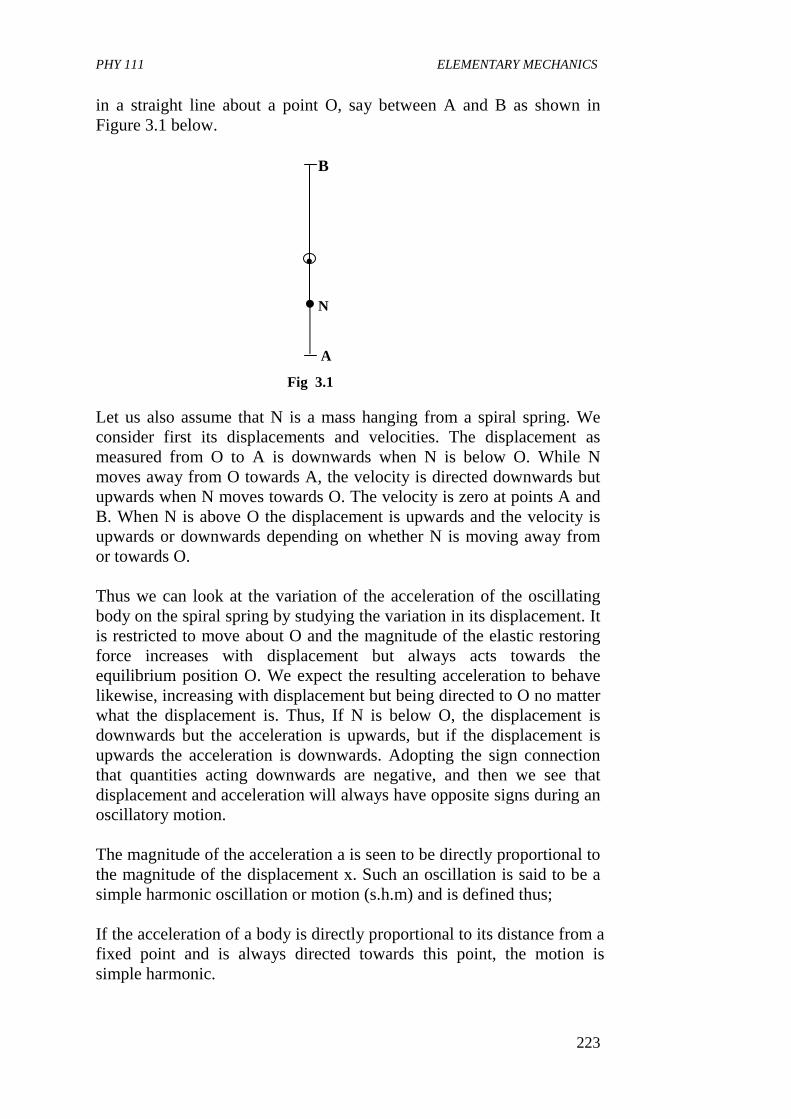
PHY 111 ELEMENTARY MECHANICS
223
B
N
A
●
in a straight line about a point O, say between A and B as shown in Figure 3.1 below.
Fig 3.1
Let us also assume that N is a mass hanging from a spiral spring. We consider first its displacements and velocities. The displacement as measured from O to A is downwards when N is below O. While N moves away from O towards A, the velocity is directed downwards but upwards when N moves towards O. The velocity is zero at points A and B. When N is above O the displacement is upwards and the velocity is upwards or downwards depending on whether N is moving away from or towards O. Thus we can look at the variation of the acceleration of the oscillating body on the spiral spring by studying the variation in its displacement. It is restricted to move about O and the magnitude of the elastic restoring force increases with displacement but always acts towards the equilibrium position O. We expect the resulting acceleration to behave likewise, increasing with displacement but being directed to O no matter what the displacement is. Thus, If N is below O, the displacement is downwards but the acceleration is upwards, but if the displacement is upwards the acceleration is downwards. Adopting the sign connection that quantities acting downwards are negative, and then we see that displacement and acceleration will always have opposite signs during an oscillatory motion. The magnitude of the acceleration a is seen to be directly proportional to the magnitude of the displacement х. Such an oscillation is said to be a simple harmonic oscillation or motion (s.h.m) and is defined thus; If the acceleration of a body is directly proportional to its distance from a fixed point and is always directed towards this point, the motion is simple harmonic.
PHY 111 ELEMENTARY MECHANICS
224
The equation relating the acceleration and displacement in a s.h.m. is a ∝ x
∴ a = (- constant) x 3.1 The negative sign indicates that acceleration is always in opposite direction to the displacement and directed to a fixed point.
Self Assessment Exercise 3.1 What kind of motion would you expect equation (3.1) to represent if the negative term were positive? Practically all mechanical motion are simple harmonic at small amplitudes or are combinations of such oscillations. Note that any system, which obeys Hook’s law, can exhibit s.h.m. This equation of s.h.m. occurs in problems in other topics in physics like sound, optics, electrical circuits and atomic physics to mention but a few. So you except to be discussing this topic a lot in your physics programme in this university. In calculus notation Eqn. (3.1) is written
2
2
2
2
2.3.tan
dt
xd
dt
dvawhere
xtConsdl
xd
==
−=
This is a second order differential equation and it could be solved to obtain the values of displacement and velocity. Can you think of other phenomena exhibiting Simple Harmonic Motion?
3.1.2 Examples of Occurrence oOf Simple Harmonic Motion We have seen that a repetitive to and fro motion about a mean position is known as an oscillatory or periodic or simple harmonic motion. Examples of such a motion can be found in: (i) The balance wheel of a watch (ii) The pistons in a gasoline engine (iii) The strings in the musical instruments (iv) The molecules in a solid body vibrating about their mean
positions in the crystal lattice (v) The beating of the heart (vi) Light waves and radio waves in space
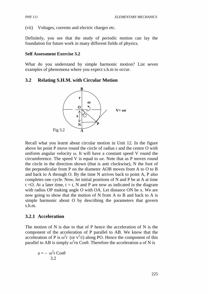
PHY 111 ELEMENTARY MECHANICS
225
(vii) Voltages, currents and electric charges etc.
Definitely, you see that the study of periodic motion can lay the foundation for future work in many different fields of physics. Self Assessment Exercise 3.2
What do you understand by simple harmonic motion? List seven examples of phenomena where you expect s.h.m to occur.
3.2 Relating S.H.M. with Circular Motion Recall what you learnt about circular motion in Unit 12. In the figure above let point P move round the circle of radius r and the centre O with uniform angular velocity ω. It will have a constant speed V round the circumference. The speed V is equal to ωr. Note that as P moves round the circle in the direction shown (that is anti clockwise), N the foot of the perpendicular from P on the diameter AOB moves from A to O to B and back to A through O. By the time N arrives back to point A, P also completes one cycle. Now, let initial positions of N and P be at A at time t =O. At a later time, t = t, N and P are now as indicated in the diagram with radius OP making angle O with OA. Let distance ON be x. We are now going to show that the motion of N from A to B and back to A is simple harmonic about O by describing the parameters that govern s.h.m. 3.2.1 Acceleration The motion of N is due to that of P hence the acceleration of N is the component of the acceleration of P parallel to AB. We know that the acceleration of P is ω2r (or v2/r) along PO. Hence the component of this parallel to AB is simply ω2rn Cosθ. Therefore the acceleration a of N is
a = – ω2r Cosθ 3.2
O
x
B
A
p
V= ωr
r ω
N Fig 3.2
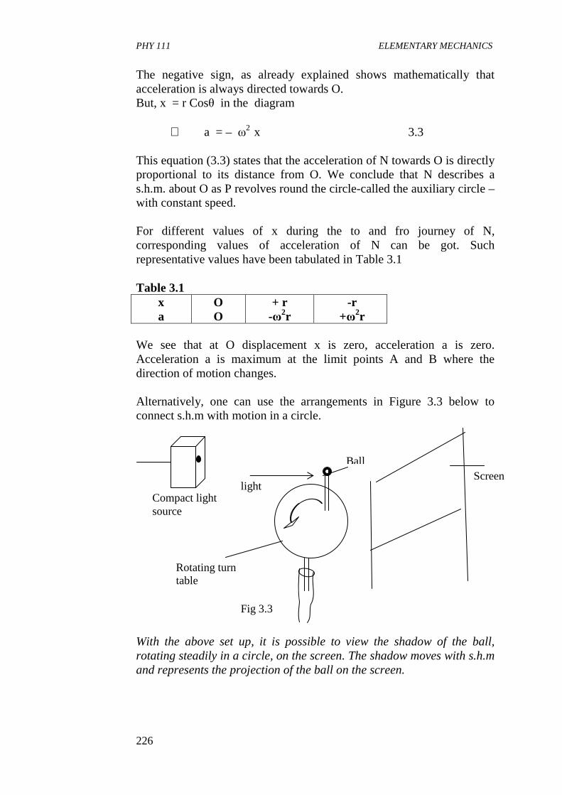
PHY 111 ELEMENTARY MECHANICS
226
The negative sign, as already explained shows mathematically that acceleration is always directed towards O. But, x = r Cosθ in the diagram
∴ a = – ω2 x 3.3
This equation (3.3) states that the acceleration of N towards O is directly proportional to its distance from O. We conclude that N describes a s.h.m. about O as P revolves round the circle-called the auxiliary circle – with constant speed. For different values of x during the to and fro journey of N, corresponding values of acceleration of N can be got. Such representative values have been tabulated in Table 3.1 Table 3.1
x a
O O
+ r -ω2r
-r +ω2r
We see that at O displacement x is zero, acceleration a is zero. Acceleration a is maximum at the limit points A and B where the direction of motion changes. Alternatively, one can use the arrangements in Figure 3.3 below to connect s.h.m with motion in a circle. With the above set up, it is possible to view the shadow of the ball, rotating steadily in a circle, on the screen. The shadow moves with s.h.m and represents the projection of the ball on the screen.
Compact light source
Screen Ball
Rotating turn table
light
Fig 3.3
PHY 111 ELEMENTARY MECHANICS
227
3.2.2 Period The period T of N is the time it takes N to do one complete to and fro motion ie to go from A to B and back to A in the Figure (3.2). In the same time, P will move round the auxiliary circles once. Therefore,
For a particular s.h.m ω is constant and so T is constant and independent of the amplitude r of the oscillation. We note that if the amplitude increases, the body travels faster and so T remains unchanged. Know that a motion which, has a constat period whatever the amplitude, is said to be isochronous. This property is an important characteristic of s.h.m. The frequency f is the number of complete oscillations per unit time. That is f =I/T. An oscillation per second is a hertz.
3.2.3 Velocity The velocity of N we have seen is the same as the component of P’s is velocity parallel to AB which
= - v sinθ from fig 3.2 = - ωr sinθ 3.5
Since sinθ is positive when 0o< θ < 180o, that is, N moving upwards, and negative when 180o<θ<360o, ie. N moving downwards, the negative sign ensures acting upwards and positive when acting downwards. The variation of the velocity of N with time (assuming P, and so N, start from A at time zero)
= – ωr Sin ωt (since θ = ωt) 3.6a
The variation of velocity of N with displacement
x = – ωr Sinθ 3.6b
( )( )
8.3
/1
7.31.1
22
2
222
xr
rxr
CosSinSinceCosr
−±=
−±=
=+−±=
ω
ω
θθθω
3422wv
rT
wrVbut
pofspeed
circleAuxiliaryofnceCircumfereT
ππ ==∴
=
=
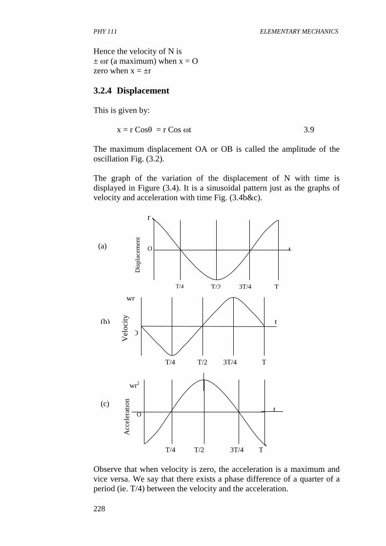
PHY 111 ELEMENTARY MECHANICS
228
Hence the velocity of N is ± ωr (a maximum) when x = O zero when x = ±r 3.2.4 Displacement This is given by:
x = r Cosθ = r Cos ωt 3.9
The maximum displacement OA or OB is called the amplitude of the oscillation Fig. (3.2). The graph of the variation of the displacement of N with time is displayed in Figure (3.4). It is a sinusoidal pattern just as the graphs of velocity and acceleration with time Fig. (3.4b&c). Observe that when velocity is zero, the acceleration is a maximum and vice versa. We say that there exists a phase difference of a quarter of a period (ie. T/4) between the velocity and the acceleration.
Dis
pla
cem
ent
O
3T/4 T
t
r
T/2 T/4
(a)
T/4 T/2 3T/4 T
Acc
eler
atio
n
wr2
O t
(c)
T 3T/4 T/2 T/4
wr
t
O
(b)
Vel
ocity
PHY 111 ELEMENTARY MECHANICS
229
I would like you to find out the phase difference between the displacement and the acceleration. 3.2.5 Expression for ω We shall now discover what quantity ω is equivalent to in a s.h.m. Recall that
a = – ω 2x
Ignoring the sign we can write
10.3/2
m
xma
mx
ma
x
a ===ω
where m is the mass of the system. The force causing the acceleration a at displacement x is ma, therefore ma/x is the force per unit displacement. Hence,
systemocillatingofmass
ntdisplacemeunitperforcew = 3.11
The period T of the s.h.m is given by
12.32
2
ntdisplacemeunitperforce
systemgoscillatinofmass
T
π
ωπ
=
=
This expression reveals that T increases if (1) the mass of the oscillating system increases and (2) the force per unit displacement decreases i.e. if the elasticity factor decreases. A vibration is simple harmonic if it’s equation of motion can be written in the form
a = – (positive constant) x 3.13
and we, by convention, represent this positive constant by ω2 since T=2π/ ω. Hence, ω is the square root of the positive constant in the acceleration –displacement equation. We have thus defined and explained the important parameters that we use in describing a s.h.m.
PHY 111 ELEMENTARY MECHANICS
230
Example. A cork floating on a pond moves in s.h.m, bobbing up and down over a range of 4cm. The period of the motion is T =1.0s and a clock is started at t = Os when the cork is at its minimum height. What are the height and velocity of the cork at t = 10.5s? Solution: Let us suppose that the cork moves along the z – axis and we set the origin z = O to be the mid point of the motion. Thus the maximum value of Z is Zmax = 2cm, and the minimum value is Zmin = -2cm. The motion takes the general form z(t) = A sin (ωt +δ ). We know the period T and from the equation ω =2π/T. The constants A and δ must be determined from other information namely, the initial conditions. The amplitude, A is the maximum excursion from equilibrium and is given by A =Zmax = |Zmin|. The phase δ, is then determined by the initial condition that the height is a minimum when t =0 s. Thus the equation determining δ is
Zmin = A sin ωt +δ/t=0 = A sin δ
When we substitute A = |Zmin|, this equation becomes Zmin = |Zmin| Sin δ. Because Zmin is negative, this result implies Sin δ = -1 When the sign function is –1,its argument is –π/2 or 3π/2. In fact, any integer multiple of 2π can be added to or subtracted from – π/2, and it is just a matter of convenience to choose the phase to be –π/2. When a simple phase such as this occurs, it is often worthwhile to expand the sine function with trigonometric identities
Sin (ω t +δ) = Sin
−2
πωt
tCos
SintCosCostSin
ω
πωπω
−=
−
=2
)(2
)(
We have used the fact that Cos (π/2) =0 and Sin (π/2) = 1. Then instead of Sin (ωt +δ), We have –Cos (ωt) appearing in the expression for z(t). We gather our results.
z = - A Cos
T
tπ2
where A = 2cm and T = 1s
PHY 111 ELEMENTARY MECHANICS
231
The velocity is the time derivative of the expression, that is
=
−−==
T
tSin
T
A
T
tSin
TA
dt
dzV
ππ
ππ
22
22
We now evaluate z and V at t = 10.5 s or 10.5 period. Both z and V repeat themselves every period, so the values of z and V at 10.5 s are the same as at 0.5 s (or 0.5 period):
Cos ( )( )
( ) ( )[ ]5.02102
)5.10()2(0.1
5.102
ππ
ππ
+=
=
Cos
Coss
s
[ ]
1
)5.0(2
−== πCos
;
( )( )
( ) ( )[ ]( )[ ]
0
5.02
5.02102
)5.10()2(0.1
5.102
==
+=
=
πππ
ππ
Sin
Sin
Sins
sSin
Thus, for t = 10.5 s Z = - A (-1) = A = + 2cm and
( ) 1002 −== scmT
Av
π
It is simple to deduce this result from physical reasoning. We are interested in where the cork is after exactly one half a period. So we look at it this way-because the cork starts at its minimum height, half a period later, it is at its maximum height, + 2cm in this case. That is a point where the cork stops momentarily and starts moving back down wards, so the velocity there is zero. Self Assessment Exercise 3.3 A particle moving with s.h.m. has velocities of 4 cm s-1 and 3cms-1 at distances of 3cm and 4 cm respectively from its equilibrium position. Find (a) the amplitude of the oscillation,
(b) the period
PHY 111 ELEMENTARY MECHANICS
232
(c) the velocity of the particle as it passes through the equilibrium position.
Solution: Let the above Figure represent the problem. Recall that
22 xrv −−= ω Assuming that velocities and displacements to the right are positive and those to the left are negative, we see that when x = + 3cm, velocity = -4cms-1; therefore
94 2 −−=− rω When x = + 4 cm, velocity = -3cm s-1; therefore
163 2 −−=− rω
Squaring and dividing these equations we get 16
9
9
162
2
−−=
r
r
Hence, r = ±5 (b) We substitute for r in one of the velocity equations to get
ω = 1s-1
sT πωπ
22 ==∴
(c) At the equilibrium position x =0
:. Velocity = ± ω 22 xr − = ± ω r = ± 5 cm s-1 4.0 CONCLUSION In this unit, you have learnt the preliminary concepts of simple harmonic motion (s.h.m.) equation.
3cms-1
3cm 4cm
4cms-1
0
PHY 111 ELEMENTARY MECHANICS
233
• that s.h.m is a periodic vibration of a body whose acceleration is directly proportional to its distance from a fixed point and is always directed towards this point i.e. a = - constant x
• at least seven phenomena where s.h.m. occurs • that s.h.m is connected to circular motion where
a = -ω2x • that the period of a s.h.m is the same as the time it takes a particle
to move round on auxiliary circle. • that the velocity of a s.h.m is given by –ωr Sinθ and the
displacement by r Cosθ • that when the velocity of a s.h.m is zero, the acceleration is
maximum and vice versa. • that the motion of a particle undergoing a s.h.m could be
represented by a sinusoidal function.
5.0 SUMMARY
What you have learnt in this unit concerns the phenomenon of simple harmonic motion. You have learnt that • s.h.m is a to-and-fro motion under the influence of an elastic
restoring force proportional to displacement and in the absence of all friction. That is a = - k x
• a complete vibration or complete cycle is one to –and fro motion regarded as one round trip.
• examplesofpriodic motion include seasons of the year, beating of the heart, lattice vibrations, the simple pendulum, electrical oscillations etc.
• s.h.m is intimately related to circular motion • te periodic time, T of a s.h.m is the time required for one
complete revolution or vibration, T= 2π/ω • The frequency f of vibration is f =1/T • In s.h.m the velocity and acceleration are also sinusoidal. • α = - ω2x • velocity v = - ω r Sinθ • displacement x = r Cosθ = r cos ωt • amplitude is the maximum displacement. • simple Harmonic motion is a special class of oscillation where
the period T is the same for all amplitudes, be they large or small.
PHY 111 ELEMENTARY MECHANICS
234
6.0 TUTOR MARKED ASSIGNMENTS (TMA) 1a. Complete the following sentences:
When a particle oscillates in a straight line with simple harmonic motion, the period of the oscillation is independent of ---------------------------------------------------------------------------------------------
b. The force towards the centre in a circular motion is called --------
------- force.
2. Use a force displacement graph to represent the way in which the force F acting on a particle depends on the displacement r? (By convention, a force acting in the direction of +r is taken to be positive force).
3. What expression is ω in a s.h.m. Derive it from first principles.
Use it to determine the expression for the period T of oscillation of the vibrating system.
4. What is a simple harmonic motion? 7.0 REFERENCES AND FURTHER READING Fishbane, P.M., Gasiorowicz, S. and Thronton, T 1996Physics for
Scientists and Engineers 2nd Ed. Prentice Hall, New Jersey Sears, F.W., Zemansky M.W and Young H.D (1975) College Physics
Addison – Wesley Publ. Co Rading U.K. Fourth Ed. Nelkon M and Parker P (1970) Heinemann Educational Books Ltd.
London. Advanced Level Physics. Duncan T.(1982) Physics A Textbook for Advanced Level Students
John Murray Publishers, London. Grounds S. and Kirby E. (1994)Longman Group UK Limited, PHYSICS
for A-LEVEL and AsLEVEL students.
PHY 111 ELEMENTARY MECHANICS
235
UNIT 2 SIMPLE HARMONIC MOTION II
CONTENTS 1.0 Introduction 2.0 Objectives 3.0 Main Body
3.1 Mass Hanging From a Coiled Spring 3.1.1 Period of Oscillation 3.1.2 Measurement of g and Effective Mass of Spring
3.2 Energy of Simple Harmonic Motion 3.2.1 Kinetic Energy 3.2.2 Potential Energy
3.3 Total Energy 4.0 Conclusion 5.0 Summary 6.0 Tutor Marked Assignment (TMAs) 7.0 References,, and Further Reading
1.0 INTRODUCTION In this Unit we shall study about harmonic motion as exhibited by a mass hanging from a coiled spring and the simple pendulum. This will bring us to the study of the energy of a simple harmonic motion. The rest of the introductory part is as covered in Unit 16. In the next Unit, we shall conclude our discussion on simple harmonic motion by studying damped oscillations, forced oscillations and resonance.
2.0 OBJECTIVES By the end of this Unit, you should be able to: • determine the period of oscillation of a mass hanging from a
coiled spring undergoing s. h. m. • determine the length of such a spring undergoing s. h. m. and also
the effective mass of the spring. • explain what a simple pendulum is and how to determine its
period of oscillation • describe an experiment to use the simple pendulum to calculate
acceleration due to gravity, g. • determine the energy of s. h. m.
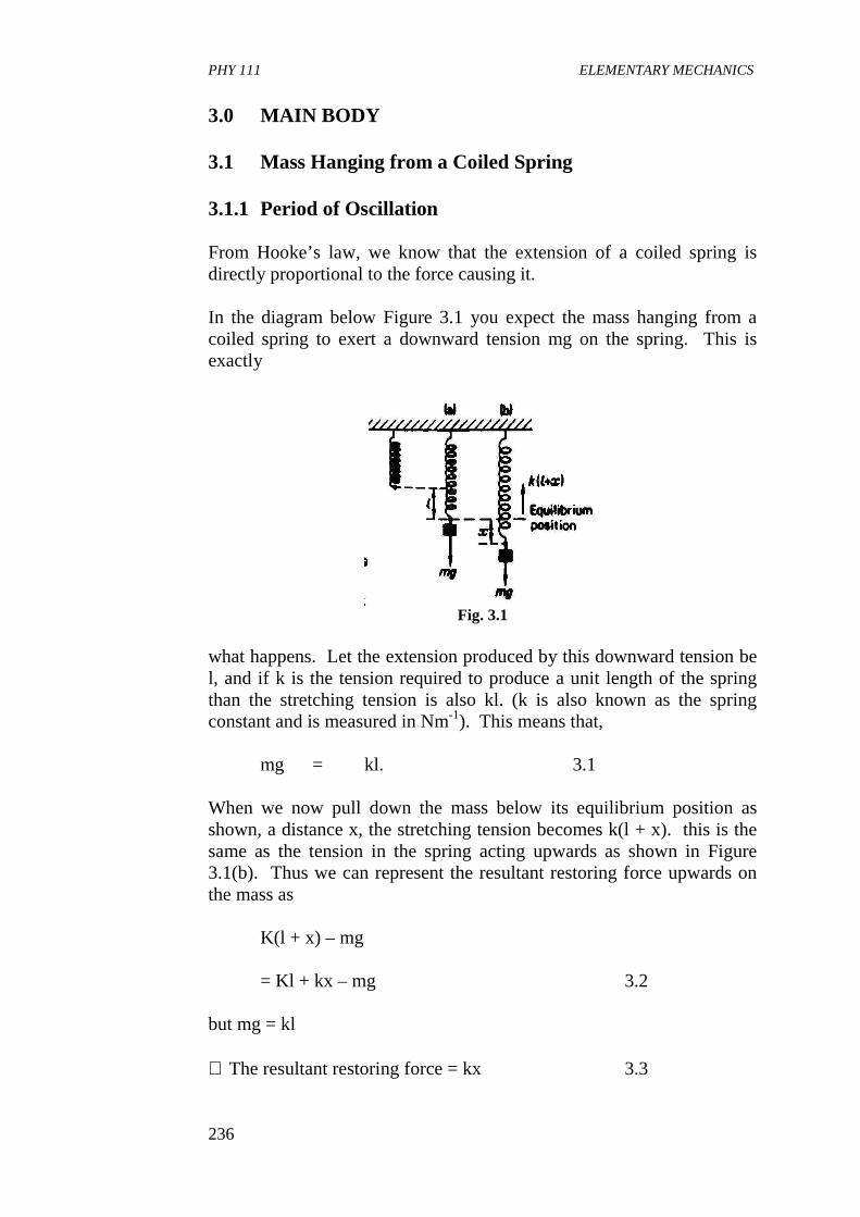
PHY 111 ELEMENTARY MECHANICS
236
3.0 MAIN BODY 3.1 Mass Hanging from a Coiled Spring 3.1.1 Period of Oscillation From Hooke’s law, we know that the extension of a coiled spring is directly proportional to the force causing it. In the diagram below Figure 3.1 you expect the mass hanging from a coiled spring to exert a downward tension mg on the spring. This is exactly
Fig. 3.1
what happens. Let the extension produced by this downward tension be l, and if k is the tension required to produce a unit length of the spring than the stretching tension is also kl. (k is also known as the spring constant and is measured in Nm-1). This means that,
mg = kl. 3.1 When we now pull down the mass below its equilibrium position as shown, a distance x, the stretching tension becomes k(l + x). this is the same as the tension in the spring acting upwards as shown in Figure 3.1(b). Thus we can represent the resultant restoring force upwards on the mass as
K(l + x) – mg = Kl + kx – mg 3.2
but mg = kl ∴ The resultant restoring force = kx 3.3
PHY 111 ELEMENTARY MECHANICS
237
Note that when we then release the mass after extension it starts moving up and down continuously in what we call oscillatory motion. If at an extension x it has acceleration a, then its equation of motion will be
ma = -kx 3.4 The minus sign shows that at the instant while displacement x is downwards (i.e positive) acceleration a, is directed upwards the equilibrium position (i.e negative).
What ω2 = k/m. Because m and k are positive constants we see that ω2 also is a positive constant. Consequently acceleration a is constant and this is a condition for a motion to be simple harmonic. We therefore conclude that the motion of the mass is simple harmonic as long as Hooke’s law is obeyed. The period T is given by
Squaring both sides we have that
T2 = 4πm/k 3.7 If in an experiment, we vary the mass m and record the square of the corresponding periodic time, T on plotting the graph of T versus m, a straight line graph will be expected. This type of experiment has actually been done many times over. It was seen that the straight line graph did not pass through the origin. And explanation was sought by scientists and it was discovered that it was because the mass of the spring itself was not taken into consideration. So it was essential to determine the effective mass undergoing simple harmonic motion and this is done as follows together with a method of determining the value of g in the next session. Example: A light spiral spring is loaded with a mass of 50g and it extends by 10cm. Calculate the period of small vertical oscillations. Take g = 10ms-2
5.32xxm
ka ω−=−=∴
6.322
k
mT π
ωπ ==
PHY 111 ELEMENTARY MECHANICS
238
Solution: Recall that the expression for the period of oscillation of a mass hanging on a spiral spring is,
When k is the force per unit displacement. Substituting values given we have
3.1.2 Measurement of g and Effective Mass of Spring.
If m is the effective mass of the spring then
Let us recall that
Kl = mg ∴m = kl/g So substituting this value for m in Eqn. (3. 8) we have
Squaring both sides of equation (3.9) gives 3.9
8.32k
mmT s+
= π
k
mglK
Ts+
= π2
10.34
4
22
22
k
gmT
gl
mg
kl
kT
s
s
−=∴
+=
π
π
k
mT π2=
s
sx
sx
T
Nmmx
NxxK
63.0
102
1025
10502
0.51010
101050
1
23
12
3
==
==∴
==∴
−
−−
−−
−
π
ππ
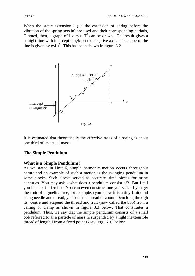
PHY 111 ELEMENTARY MECHANICS
239
When the static extension l (i.e the extension of spring before the vibration of the spring sets in) are used and their corresponding periods, T noted, then, a graph of l versus T2 can be drawn. The result gives a straight line with intercept gms/k on the negative axis. The slope of the line is given by g/4π2. This has been shown in figure 3.2.
Fig. 3.2 It is estimated that theoretically the effective mass of a spring is about one third of its actual mass. The Simple Pendulum
What is a Simple Pendulum? As we stated in Unit16, simple harmonic motion occurs throughout nature and an example of such a motion is the swinging pendulum in some clocks. Such clocks served as accurate, time pieces for many centuries. You may ask - what does a pendulum consist of? But I tell you it is not far fetched. You can even construct one yourself. If you get the fruit of a gmelina tree, for example, (you know it is a tiny fruit) and using needle and thread, you pass the thread of about 20cm long through its centre and suspend the thread and fruit (now called the bob) from a ceiling or clamp as shown in figure 3.3 below. That constitutes a pendulum. Thus, we say that the simple pendulum consists of a small bob referred to as a particle of mass m suspended by a light inextensible thread of length l from a fixed point B say. Fig.(3.3). below
D
Slope = CD/BD = g/4п2
Intercept OA=gms/k
T2
l C
A
B
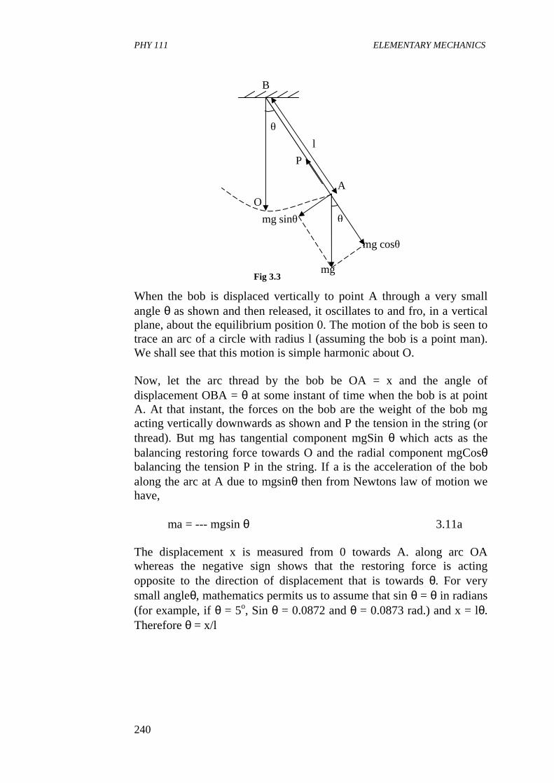
PHY 111 ELEMENTARY MECHANICS
240
When the bob is displaced vertically to point A through a very small angle θ as shown and then released, it oscillates to and fro, in a vertical plane, about the equilibrium position 0. The motion of the bob is seen to trace an arc of a circle with radius l (assuming the bob is a point man). We shall see that this motion is simple harmonic about O.
Now, let the arc thread by the bob be OA = x and the angle of displacement OBA = θ at some instant of time when the bob is at point A. At that instant, the forces on the bob are the weight of the bob mg acting vertically downwards as shown and P the tension in the string (or thread). But mg has tangential component mgSin θ which acts as the balancing restoring force towards O and the radial component mgCosθ balancing the tension P in the string. If a is the acceleration of the bob along the arc at A due to mgsinθ then from Newtons law of motion we have,
ma = --- mgsin θ 3.11a
The displacement x is measured from 0 towards A. along arc OA whereas the negative sign shows that the restoring force is acting opposite to the direction of displacement that is towards θ. For very small angleθ, mathematics permits us to assume that sin θ = θ in radians (for example, if θ = 5o, Sin θ = 0.0872 and θ = 0.0873 rad.) and x = lθ. Therefore θ = x/l
Fig 3.3
A
B
l
mg cosθ
mg
P
θ
O
mg sinθ θ
PHY 111 ELEMENTARY MECHANICS
241
Hence,
We can then calculate that the motion of the bob is simple harmonic if the oscillations are of small amplitude θ as we assumed. In short θ should not exceed 100. The period T for the simple pendulum, is given by
We notice that T does not depend on the amplitude of the oscillations. For a particular location on the surface of the earth where g is constant, the period of oscillation of a simple pendulum is seen to depend only on the length of the pendulum.
3.1.2 Measurement of g. With a Simple Pendulum The simple pendulum method provides a fairly accurate means of determining acceleration due to gravity g. When the periodic time T for a simple pendulum is measured and recorded for corresponding different values of the length, l of the string supporting the pendulum bob, a plot of l versus T2 gives a straight line so drawn so that the points on the graph are evenly distributed about the line. An example of such a result is shown in figure 3.4.
13.3
12.3
16.3
2
2
xa
havewel
gsetting
xl
ga
bl
xmgmgma
ω
ω
θ
−=
=
−=∴
−==
15.32
14.3/
22
g
l
lgwT
π
ππ
=
==
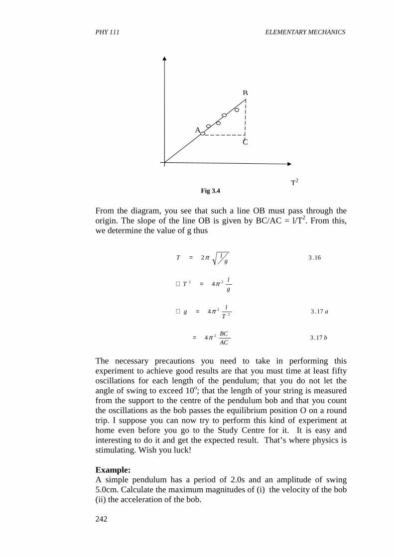
PHY 111 ELEMENTARY MECHANICS
242
From the diagram, you see that such a line OB must pass through the origin. The slope of the line OB is given by BC/AC = l/T2. From this, we determine the value of g thus
The necessary precautions you need to take in performing this experiment to achieve good results are that you must time at least fifty oscillations for each length of the pendulum; that you do not let the angle of swing to exceed 10o; that the length of your string is measured from the support to the centre of the pendulum bob and that you count the oscillations as the bob passes the equilibrium position O on a round trip. I suppose you can now try to perform this kind of experiment at home even before you go to the Study Centre for it. It is easy and interesting to do it and get the expected result. That’s where physics is stimulating. Wish you luck!
Example: A simple pendulum has a period of 2.0s and an amplitude of swing 5.0cm. Calculate the maximum magnitudes of (i) the velocity of the bob (ii) the acceleration of the bob.
bAC
BC
aT
lg
g
lT
glT
17.34
17.34
4
16.32
2
22
22
π
π
π
π
=
=∴
=∴
=
Fig 3.4 T2
B
C
A
PHY 111 ELEMENTARY MECHANICS
243
Solution: Recall that,
The velocity is a maximum at the equilibrium position where x displacement = 0 Recall the expression for the variation of velocity with displacement x
which
(b) The acceleration is maximum at the limits of the swing where x = r = ± 5.0cm ∴ a = -ω2r = -π x 5cm s-2 = -50cm s-2
Self Assessment Exercise. 3.1 A simple pendulum 2.0m long is suspended in a region where g = 9.81m s-2. The point mass at the end is displaced from the vertical and given a small push, so its maximum speed is 0.11m s-1. What is the maximum horizontal displacement of the mass from the vertical line it makes when at rest? Assume that all the motion take place at small angles.
Solution: The angle that the string makes the vertical varies harmonically, θ = θocos(ωt + δ), where ω is the angular frequency. The horizontal displacement from the vertical is x = lθ (where l is the strings length) as long as θ remains small. Thus x also varies harmonically.
ωπ /2=T
1
0.2/2/2−=
==∴
s
sT
πππω
22 xr −±= ω
1
1
2
16
5
25
max.0
−
−
±=
±=±=
=∴
scm
scm
cmv
velocityimumeixwhen
ππ
PHY 111 ELEMENTARY MECHANICS
244
x = A cos (ωt + δ) where A = l θo. This is the quantity we want to find.
Another good small angle approximation is that the vertical component of the velocity is small, so v = dx/dt. Thus we have
From this expression we see that v varies harmonically with amplitude Aω. The maximum value of v occurs when θ = 0. That is when the pendulum is passing through its equilibrium position. This is given by Vmax = Aω = 0.11m s-1 as given. From the following equation,
We observe that this horizontal displacement 5.0cm is indeed small compared to the length of the pendulum so our small angle approximations are good. The figures below illustrate the motion.
)(
)][cos()cos([
δωω
δωδω
+−=∴
+=+=
tSinAv
tdt
dAtA
dt
dv
m
srad
smVA
AVfromso
sradm
sml
g
isthatseewe
l
gwithtSino
05.0
21.2
11.0
,
21.20.2
81.9
)(0
1
1max
max
12
=
==
=
===
=+=
−
−
−−
ω
ω
ω
ω
ωδωθ
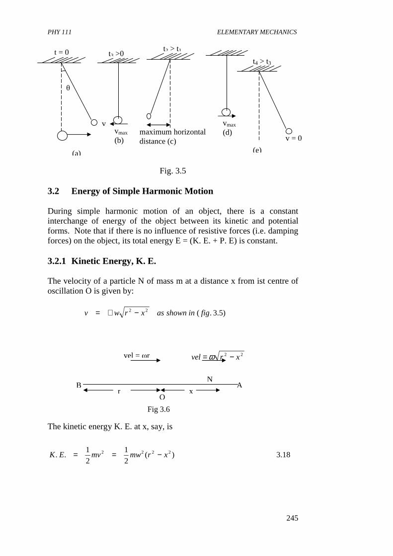
PHY 111 ELEMENTARY MECHANICS
245
Fig. 3.5
3.2 Energy of Simple Harmonic Motion
During simple harmonic motion of an object, there is a constant interchange of energy of the object between its kinetic and potential forms. Note that if there is no influence of resistive forces (i.e. damping forces) on the object, its total energy E = (K. E. + P. E) is constant. 3.2.1 Kinetic Energy, K. E. The velocity of a particle N of mass m at a distance x from ist centre of oscillation O is given by:
22 xrvel −= ω The kinetic energy K. E. at x, say, is
)5.3.(22 figinshownasxrwv −+=
18.3)(2
1
2
1.. 2222 xrmwmvEK −==
(a)
t = 0
θ
v
(e)
t4 > t3
v = 0
t2 > t1
maximum horizontal distance (c)
t3 >0
vmax (b)
vmax (d)
vel = ωr
r B A
O x
N
Fig 3.6
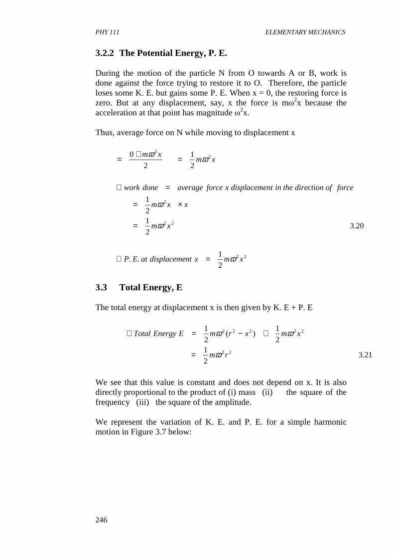
PHY 111 ELEMENTARY MECHANICS
246
3.2.2 The Potential Energy, P. E. During the motion of the particle N from O towards A or B, work is done against the force trying to restore it to O. Therefore, the particle loses some K. E. but gains some P. E. When x = 0, the restoring force is zero. But at any displacement, say, x the force is mω2x because the acceleration at that point has magnitude ω2x. Thus, average force on N while moving to displacement x
3.3 Total Energy, E The total energy at displacement x is then given by K. E + P. E
We see that this value is constant and does not depend on x. It is also directly proportional to the product of (i) mass (ii) the square of the frequency (iii) the square of the amplitude. We represent the variation of K. E. and P. E. for a simple harmonic motion in Figure 3.7 below:
21.32
12
1)(
2
1
22
22222
rm
xmxrmEEnergyTotal
ω
ωω
=
+−=∴
22
22
2
22
2
1..
20.32
12
1
2
1
2
0
xmxntdisplacemeatEP
xm
xxm
forceofdirectiontheinntdisplacemexforceaveragedonework
xmxm
ω
ω
ω
ωω
=∴
=
×=
=∴
=+=
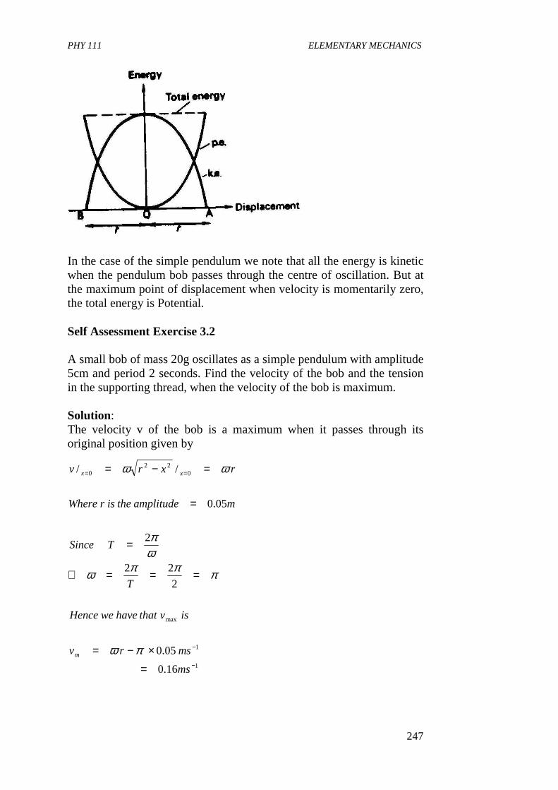
PHY 111 ELEMENTARY MECHANICS
247
In the case of the simple pendulum we note that all the energy is kinetic when the pendulum bob passes through the centre of oscillation. But at the maximum point of displacement when velocity is momentarily zero, the total energy is Potential. Self Assessment Exercise 3.2 A small bob of mass 20g oscillates as a simple pendulum with amplitude 5cm and period 2 seconds. Find the velocity of the bob and the tension in the supporting thread, when the velocity of the bob is maximum. Solution: The velocity v of the bob is a maximum when it passes through its original position given by
1
1
max
022
0
16.0
05.0
2
22
2
05.0
//
−
−
==
=
×−=
===∴
=
=
=−=
ms
msrv
isvthathaveweHence
T
TSince
mamplitudetheisrWhere
rxrv
m
xx
πω
πππω
ωπ
ωω
PHY 111 ELEMENTARY MECHANICS
248
Suppose P is the tension in the thread. The net force acting towards the centre of the circle along which the bob moves is given by (P – mg). The acceleration towards the centre of the circle, which is the point of suspension, is v2
max/l where l is the length of the pendulum.
4.0 CONCLUSION In this Unit, you have learnt • about the period of oscillation of a mass hanging from a coiled
spring. • how to measure the acceleration due to gravity g and the effective
mass of the spring. • to determine the period of oscillation of a simple pendulum and g
also. • to determine the kinetic energy, potential energy and total energy
of a simple harmonic motion. 5.0 SUMMARY What you have learnt in the unit concerns simple harmonic motion as it relates to a mass hanging from a coiled spring and a simple pendulum.
• that the vibration of mass hanging from a coiled spring is in the
vertical plane with mg = kl K is the spring constant With the restoring force given by kx Hence with an acceleration of a, for an extension x the equation of motion for the mass is
l
mVmgP m
2
=−∴
NP
gTl
g
lTcall
mgP lmVm
2
2
2
2
2
1065.19
4
28.9
4
2Re
2
×=∴
×==∴
=
+=∴
ππ
π
PHY 111 ELEMENTARY MECHANICS
249
ma = -kx.
For ω2 = k/m, ω = angular velocity
• the length of the spring is given by
Where ms is the mass of the spring
• that the period T of the simple pendulum is given by
From where g the acceleration due to gravity could be determined more accurately as
• that the kinetic energy of a simple harmonic motion is
• that Potential energy of s. h. m. is
at displacement x
• that total Energy of s. h. m. is given by
k
mT π
ωπ
22 ==
k
gmT
gl s==
24π
g
lT π2=
224
T
lg π=
)(2
1.. 222 xrmEK −= ω
22
2
1. xmEP ω=
22
2
1.... rmEPEK ω=+
PHY 111 ELEMENTARY MECHANICS
250
6.0 TUTOR MARKED ASSIGNMENT 1a. Define simple harmonic motion and state the relation between
displacement from its mean position and the restoring force when a body executes simple harmonic motion.
b. A body is supported by a spiral spring and causes a stretch of
1.5cm in the spring. If the mass is now set in vertical oscillation of small amplitude, what is the periodic time of oscillation?.
2. A flat steel strip is mounted on a support. By attaching a spring
balance to the free end and pulling side-ways, we determine that the force is proportional to the displacement, a force of 4N causing a displacement of 0.02m. Then a 2kg body is attached to the end, and pulled aside, a distance 0.04m and released. (a) Find the force constant of the spring (b) Find the frequency and period of vibration. (c) Compute the maximum velocity attained by the vibrating
body. (d) Compute the maximum acceleration (e) Compute the velocity and acceleration when the body has
moved half way toward the centre from its initial position. (f) How long a time is it required for the body to move half
way in to the centre from its initial position? 7.0 REFERENCES AND FURTHER READING Fishbane P. M., Gasiorowicz S, Thronton S. T., (1996). Physics for
Scientists and Engineers, 2nd Ed. Prentice Hall Publ. New Jersey Sears F. W., Zemansky M. W. and Young H. D. (1975) College Physics
(4th Ed). Addison-Wesley Publ. Co. Reading, U. K Nelkon M. and Parker P. (1970) Advanced Level Physics Heinemann
Educational Books Ltd, London, “Advanced Level Physics”. Duncan T. (1982). John Murray (Publishers) Ltd. London. PHYSICS A
Textbook for Advanced Level Students
PHY 111 ELEMENTARY MECHANICS
251
UNIT 3 SIMPLE HARMONIC MOTION III CONTENTS 1.0 Introduction 2.0 Objectives 3.0 Main Body
3.1 Damped Oscillations 3.2 Forced Oscillation and Resonance
3.2.1 Barton’s Pendulums 3.2.2 Examples of Resonance 3.2.3 Energy Considerations 3.2.4 Phase
3.3 S.H.M. – a Mathematical Model 3.4 The Physical Pendulum
4.0 Conclusion 5.0 Summary 6.0 Teacher Marked Assignments (TMAs) 7.0 References and Further Reading 1.0 INTRODUCTION See introduction of Units 16 and 17. In this unit you will study about damped simple harmonic motion, s. h. m., forced oscillation and resonance. These will lead us to see that s. h. m. is a mathematical model. We shall conclude by considering a physical pendulum where we observe that in reality the pendulum string and bob can have dimensions and some mass. The importance of s. h. m. to life is also emphasized in this unit. After which we shall move on to the motion of rigid bodies in the next unit because this is what we experience in real life situations. There, you will learn about translational and rotational motions of rigid bodies. 2.0 OBJECTIVES By the end of this Unit, you should be able to,
• explain damped oscillations-stating the conditions under which a
physical oscillator can experience it. • draw the wave patterns of the effects of different types of
damping phenomenon. • state some applications of damping phenomenon • define resonance and give examples of its occurrence • state the importance of resonance • show that the period of a physical pendulum is given by
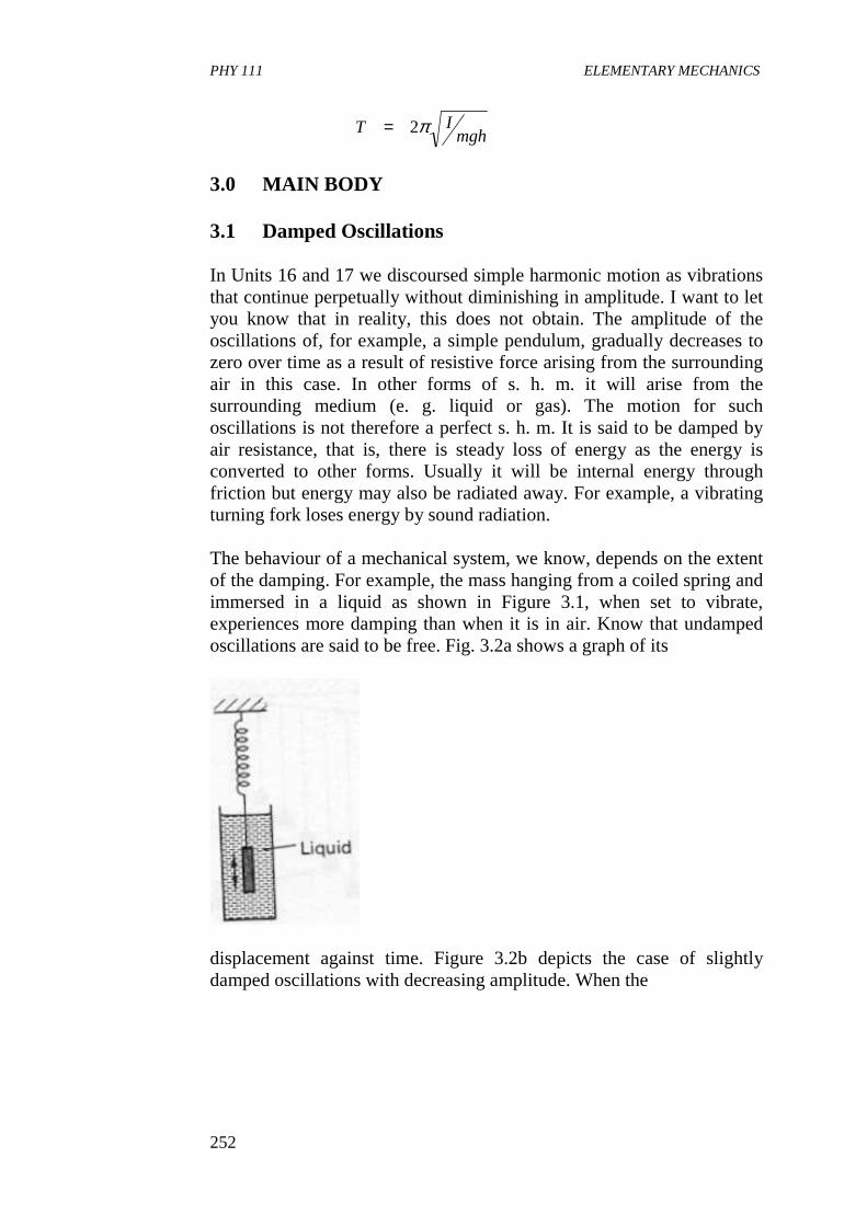
PHY 111 ELEMENTARY MECHANICS
252
3.0 MAIN BODY 3.1 Damped Oscillations In Units 16 and 17 we discoursed simple harmonic motion as vibrations that continue perpetually without diminishing in amplitude. I want to let you know that in reality, this does not obtain. The amplitude of the oscillations of, for example, a simple pendulum, gradually decreases to zero over time as a result of resistive force arising from the surrounding air in this case. In other forms of s. h. m. it will arise from the surrounding medium (e. g. liquid or gas). The motion for such oscillations is not therefore a perfect s. h. m. It is said to be damped by air resistance, that is, there is steady loss of energy as the energy is converted to other forms. Usually it will be internal energy through friction but energy may also be radiated away. For example, a vibrating turning fork loses energy by sound radiation. The behaviour of a mechanical system, we know, depends on the extent of the damping. For example, the mass hanging from a coiled spring and immersed in a liquid as shown in Figure 3.1, when set to vibrate, experiences more damping than when it is in air. Know that undamped oscillations are said to be free. Fig. 3.2a shows a graph of its
displacement against time. Figure 3.2b depicts the case of slightly damped oscillations with decreasing amplitude. When the
mghIT π2=
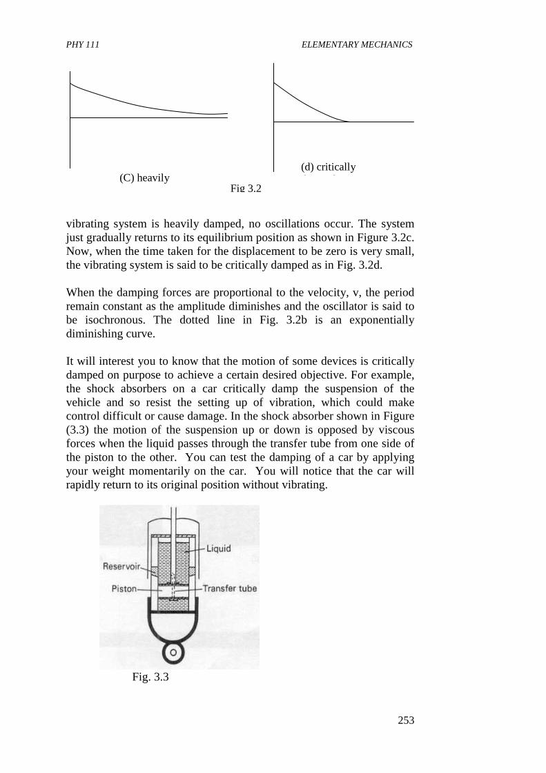
PHY 111 ELEMENTARY MECHANICS
253
vibrating system is heavily damped, no oscillations occur. The system just gradually returns to its equilibrium position as shown in Figure 3.2c. Now, when the time taken for the displacement to be zero is very small, the vibrating system is said to be critically damped as in Fig. 3.2d. When the damping forces are proportional to the velocity, v, the period remain constant as the amplitude diminishes and the oscillator is said to be isochronous. The dotted line in Fig. 3.2b is an exponentially diminishing curve. It will interest you to know that the motion of some devices is critically damped on purpose to achieve a certain desired objective. For example, the shock absorbers on a car critically damp the suspension of the vehicle and so resist the setting up of vibration, which could make control difficult or cause damage. In the shock absorber shown in Figure (3.3) the motion of the suspension up or down is opposed by viscous forces when the liquid passes through the transfer tube from one side of the piston to the other. You can test the damping of a car by applying your weight momentarily on the car. You will notice that the car will rapidly return to its original position without vibrating.
Fig. 3.3
(C) heavily (d) critically damped
Fig 3.2
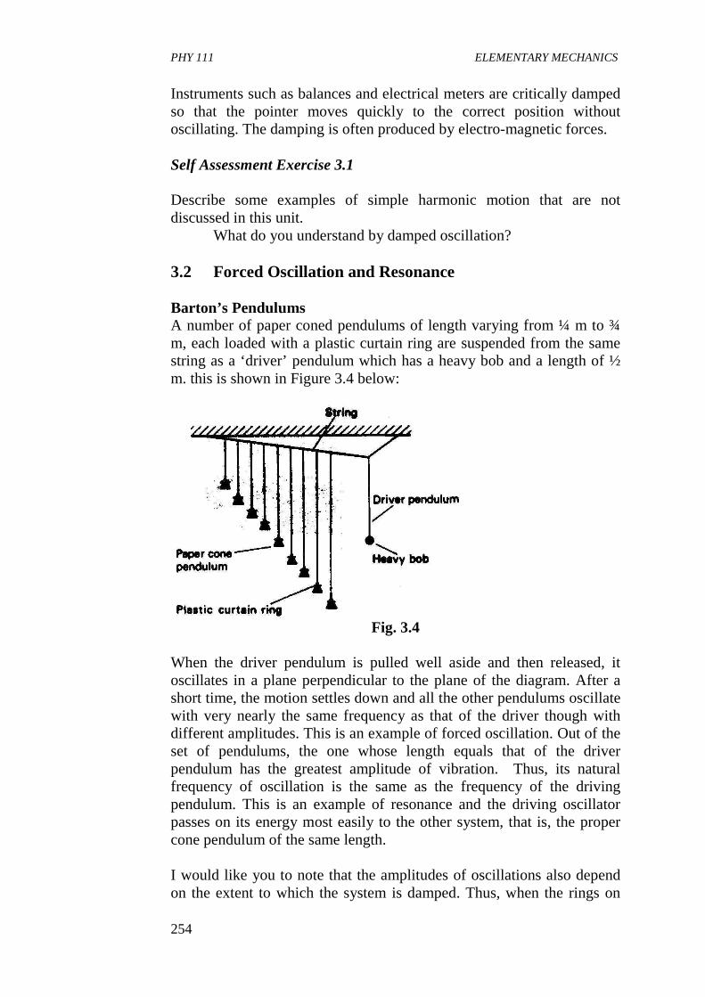
PHY 111 ELEMENTARY MECHANICS
254
Instruments such as balances and electrical meters are critically damped so that the pointer moves quickly to the correct position without oscillating. The damping is often produced by electro-magnetic forces.
Self Assessment Exercise 3.1 Describe some examples of simple harmonic motion that are not discussed in this unit.
What do you understand by damped oscillation?
3.2 Forced Oscillation and Resonance
Barton’s Pendulums A number of paper coned pendulums of length varying from ¼ m to ¾ m, each loaded with a plastic curtain ring are suspended from the same string as a ‘driver’ pendulum which has a heavy bob and a length of ½ m. this is shown in Figure 3.4 below:
Fig. 3.4
When the driver pendulum is pulled well aside and then released, it oscillates in a plane perpendicular to the plane of the diagram. After a short time, the motion settles down and all the other pendulums oscillate with very nearly the same frequency as that of the driver though with different amplitudes. This is an example of forced oscillation. Out of the set of pendulums, the one whose length equals that of the driver pendulum has the greatest amplitude of vibration. Thus, its natural frequency of oscillation is the same as the frequency of the driving pendulum. This is an example of resonance and the driving oscillator passes on its energy most easily to the other system, that is, the proper cone pendulum of the same length. I would like you to note that the amplitudes of oscillations also depend on the extent to which the system is damped. Thus, when the rings on
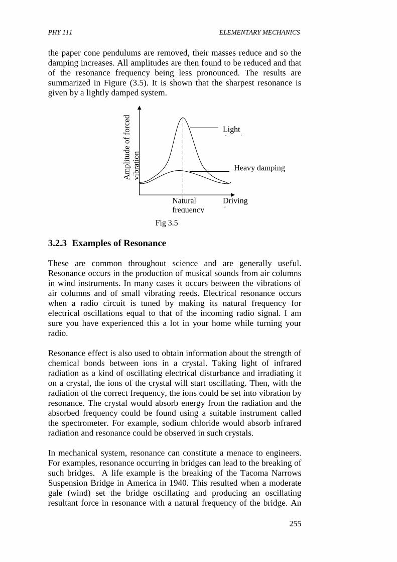
PHY 111 ELEMENTARY MECHANICS
255
the paper cone pendulums are removed, their masses reduce and so the damping increases. All amplitudes are then found to be reduced and that of the resonance frequency being less pronounced. The results are summarized in Figure (3.5). It is shown that the sharpest resonance is given by a lightly damped system.
3.2.3 Examples of Resonance
These are common throughout science and are generally useful. Resonance occurs in the production of musical sounds from air columns in wind instruments. In many cases it occurs between the vibrations of air columns and of small vibrating reeds. Electrical resonance occurs when a radio circuit is tuned by making its natural frequency for electrical oscillations equal to that of the incoming radio signal. I am sure you have experienced this a lot in your home while turning your radio. Resonance effect is also used to obtain information about the strength of chemical bonds between ions in a crystal. Taking light of infrared radiation as a kind of oscillating electrical disturbance and irradiating it on a crystal, the ions of the crystal will start oscillating. Then, with the radiation of the correct frequency, the ions could be set into vibration by resonance. The crystal would absorb energy from the radiation and the absorbed frequency could be found using a suitable instrument called the spectrometer. For example, sodium chloride would absorb infrared radiation and resonance could be observed in such crystals. In mechanical system, resonance can constitute a menace to engineers. For examples, resonance occurring in bridges can lead to the breaking of such bridges. A life example is the breaking of the Tacoma Narrows Suspension Bridge in America in 1940. This resulted when a moderate gale (wind) set the bridge oscillating and producing an oscillating resultant force in resonance with a natural frequency of the bridge. An
Am
plitu
de o
f for
ced
vibr
atio
n
Natural frequency
Driving frequency
Light damping
Heavy damping
Fig 3.5
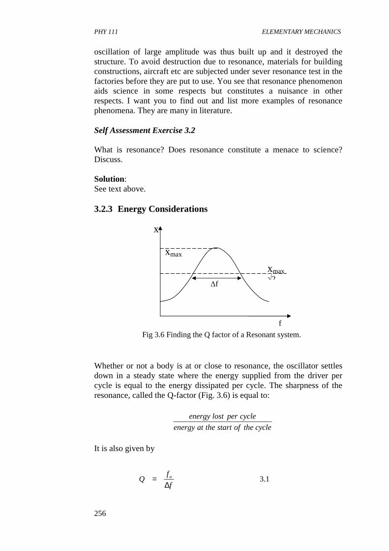
PHY 111 ELEMENTARY MECHANICS
256
oscillation of large amplitude was thus built up and it destroyed the structure. To avoid destruction due to resonance, materials for building constructions, aircraft etc are subjected under sever resonance test in the factories before they are put to use. You see that resonance phenomenon aids science in some respects but constitutes a nuisance in other respects. I want you to find out and list more examples of resonance phenomena. They are many in literature.
Self Assessment Exercise 3.2 What is resonance? Does resonance constitute a menace to science? Discuss. Solution: See text above.
3.2.3 Energy Considerations
Whether or not a body is at or close to resonance, the oscillator settles down in a steady state where the energy supplied from the driver per cycle is equal to the energy dissipated per cycle. The sharpness of the resonance, called the Q-factor (Fig. 3.6) is equal to:
It is also given by
Fig 3.6 Finding the Q factor of a Resonant system.
x
xmax
f
xmax √2
∆f
1.3f
fQ o
∆=
cycletheofstarttheatenergy
cycleperlostenergy
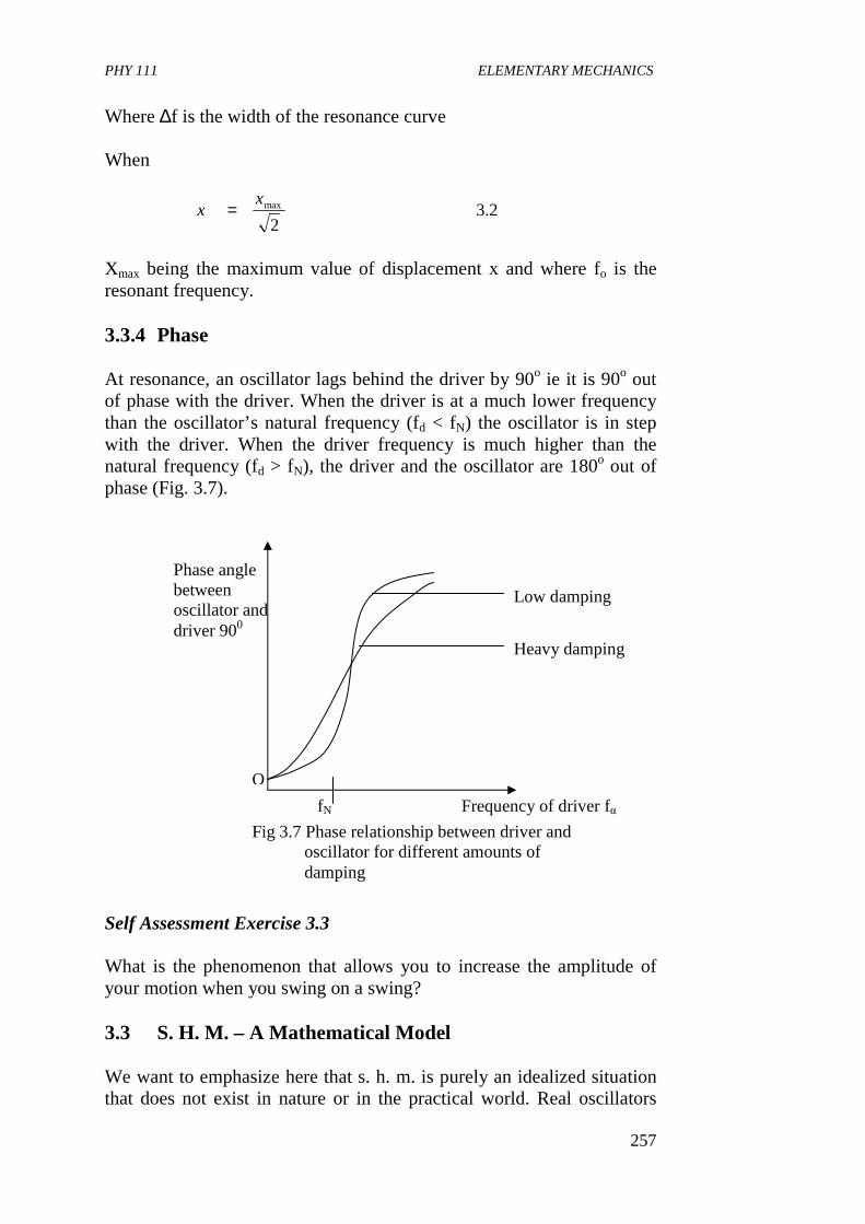
PHY 111 ELEMENTARY MECHANICS
257
Where ∆f is the width of the resonance curve When
Xmax being the maximum value of displacement x and where fo is the resonant frequency. 3.3.4 Phase At resonance, an oscillator lags behind the driver by 90o ie it is 90o out of phase with the driver. When the driver is at a much lower frequency than the oscillator’s natural frequency (fd < fN) the oscillator is in step with the driver. When the driver frequency is much higher than the natural frequency (fd > fN), the driver and the oscillator are 180o out of phase (Fig. 3.7). Self Assessment Exercise 3.3 What is the phenomenon that allows you to increase the amplitude of your motion when you swing on a swing? 3.3 S. H. M. – A Mathematical Model We want to emphasize here that s. h. m. is purely an idealized situation that does not exist in nature or in the practical world. Real oscillators
2.32
maxxx =
O
Phase angle between oscillator and driver 900
Frequency of driver fα fN
Low damping
Heavy damping
Fig 3.7 Phase relationship between driver and oscillator for different amounts of damping
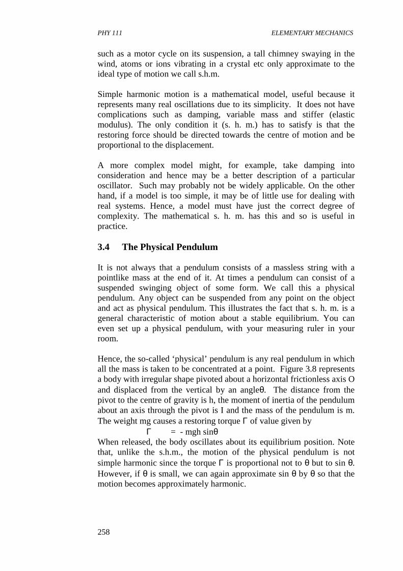
PHY 111 ELEMENTARY MECHANICS
258
such as a motor cycle on its suspension, a tall chimney swaying in the wind, atoms or ions vibrating in a crystal etc only approximate to the ideal type of motion we call s.h.m. Simple harmonic motion is a mathematical model, useful because it represents many real oscillations due to its simplicity. It does not have complications such as damping, variable mass and stiffer (elastic modulus). The only condition it (s. h. m.) has to satisfy is that the restoring force should be directed towards the centre of motion and be proportional to the displacement. A more complex model might, for example, take damping into consideration and hence may be a better description of a particular oscillator. Such may probably not be widely applicable. On the other hand, if a model is too simple, it may be of little use for dealing with real systems. Hence, a model must have just the correct degree of complexity. The mathematical s. h. m. has this and so is useful in practice.
3.4 The Physical Pendulum It is not always that a pendulum consists of a massless string with a pointlike mass at the end of it. At times a pendulum can consist of a suspended swinging object of some form. We call this a physical pendulum. Any object can be suspended from any point on the object and act as physical pendulum. This illustrates the fact that s. h. m. is a general characteristic of motion about a stable equilibrium. You can even set up a physical pendulum, with your measuring ruler in your room. Hence, the so-called ‘physical’ pendulum is any real pendulum in which all the mass is taken to be concentrated at a point. Figure 3.8 represents a body with irregular shape pivoted about a horizontal frictionless axis O and displaced from the vertical by an angleθ. The distance from the pivot to the centre of gravity is h, the moment of inertia of the pendulum about an axis through the pivot is I and the mass of the pendulum is m. The weight mg causes a restoring torque Γ of value given by
Γ = - mgh sinθ When released, the body oscillates about its equilibrium position. Note that, unlike the s.h.m., the motion of the physical pendulum is not simple harmonic since the torque Γ is proportional not to θ but to sin θ. However, if θ is small, we can again approximate sin θ by θ so that the motion becomes approximately harmonic.
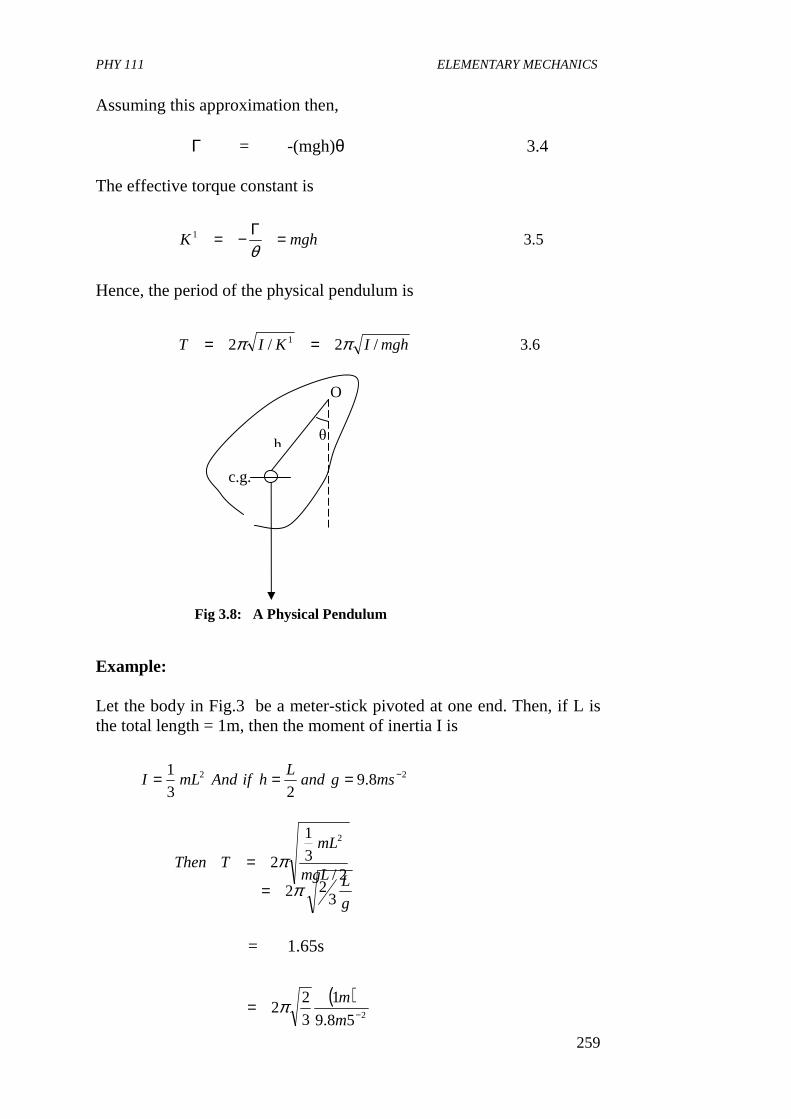
PHY 111 ELEMENTARY MECHANICS
259
Assuming this approximation then, Γ = -(mgh)θ 3.4 The effective torque constant is
Hence, the period of the physical pendulum is
Example:
Let the body in Fig.3 be a meter-stick pivoted at one end. Then, if L is the total length = 1m, then the moment of inertia I is
= 1.65s
5.31 mghK =Γ−=θ
6.3/2/2 1 mghIKIT ππ ==
22 8.923
1 −=== msgandL
hifAndmLI
2/3
1
2
2
mgL
mLTThen π=
g
L3
22π=
( )258.9
1
3
22 −=
m
mπ
O
θ
c.g.
h
Fig 3.8: A Physical Pendulum
PHY 111 ELEMENTARY MECHANICS
260
Self Assessment Exercise 3 Find the moment of inertia of the complex shape – a connecting rod pivoted about a horizontal knife edge. The rod has mass 2kg at its centre of gravity (c.g) is at 0.2 below the knife edge. Solution: we apply the principle that period
So, we set the system into vibration and using 100 complete vibration in 120s the period was found to be 1.2.5
Rearranging, we have
= 0.143 kg m2
4.0 CONCLUSIONS
In this Unit you have learnt that,
• most real oscillators are damped, that is, there is steady loss of energy as it is converted to their forms
• damping of oscillators is due to the presence of additional velocity - dependent drag, or resistive forces causing the amplitude of the vibrating particle to decrease.
• when a system that, by itself, would move in simple harmonic motion is driven by a force with sinusoidal time dependence, the system moves with the frequency of the driving force. The amplitude of the resulting motion of the system shows resonant behaviour when the frequency of the driving force equals the natural frequency of the system.
• the width of the resonance peak is inversely related to the exponential rate of fall off of the undriven system due to damping.
• s. h.m is a mathematical model.
mgh
IT π2=
2.08.9222.1
2 xmsxkg
IsT −==∴ π
( ) ( ) ( ) ( )2
22
4
2.08.922.1
πmmskg
I−
=
PHY 111 ELEMENTARY MECHANICS
261
5.0 SUMMARY
What you have learnt in this unit concerns damped simple harmonic oscillations, forced oscillations and resonance and the physical pendulum. You have learnt that
• the amplitude of oscillations of a particle in s.h.m. is damped by
resistive forces due to the surrounding medium. • when the amplitude is reduced to zero in minimal time the system
is said to be critically damped • when the damping forces are proportional to velocity, the period
remain constant as the amplitude diminishes the oscillator is said to be isochronous
• resonance occurs when the driving frequency is the same as the natural frequency of the oscillator resulting in a maximum amplitude of oscillation.
• the sharpness of the resonance curve is called the Q-factor and is given by
Q = fo/∆f
where ∆f is the width of the resonance curve when
Xmax is the maximum displacement and fo is the resonant frequency.
• the period of a physical pendulum is
6.0 TUTOR MARKED ASSIGNMENTS
1. A light helical spring is suspended from a beam, and a mass m, is
attached at its lower end, causing the spring to extend through a distance a. The mass is now caused to execute vertical oscillations of amplitude a. When the mass is at its lowest point, what is the energy stored in the spring?
2. A wire of mass per unit length 5.0 g m-1 is stretched between two points 30 cm apart. The tension in the wire is 70N. Calculate the frequency of the sound emitted by the wire when it oscillates in its fundamental mode.
b. Explain, with reference to this example, the term damped harmonic motion.
2/maxxx =
mghIT /2π=
PHY 111 ELEMENTARY MECHANICS
262
3. A thin rod of mass M and length L swings from its end as a physical pendulum. What is the period of the oscillatory motion for small angles? Find the length L of the simple pendulum that has the same period as the swinging rod.
7.0 REFERENCE AND FURTHER READING
Fishbane P. M., Gasiorowicz S., Thronton S. T., (1996) Physics for
Scientists and Engineers, 2nd Ed. Prentice Hall, New Jersey. Sears F. W., Zemansky M. W. and Young H. D. (1975).College Physics,
Addison-Wesley Publ. Co. Reading, U. K. Nelkon M. and Parker P (1970).Advanced Leve Physics, Heinemann
Educational Books Ltd, London.,U.K Duncan T. (1982).Physics, A Text Book for Advanced Level Students
John Murray (Publishers) Ltd. London
g
L
g
lT pSimple 3
222. ππ ==
Ll 32=∴
PHY 111 ELEMENTARY MECHANICS
263
UNIT 4 RIGID BODY DYNAMICS 1 CONTENTS 1.0 Introduction 2.0 Objectives 3.0 Main Body
3.1 A Rigid Body and Its Motion 3.1.1 What is a Rigid Body 3.1.2 Translational Motion of a Rigid Body 3.1.3 Rotational Motion of a Rigid Body 3.1.4 General Motion of a Rigid Body
3.2 Moment of Inertia 3.2.1 Radius of Gyration 3.2.2 The Dumbbell
3.3 Moments And Couples 3.3.1 Equilibrium of Coplanar Forces
4.0 Conclusion 5.0 Summary 6.0 Tutor Marked Assignment 7.0 References and Further Reading. 1.0 INTRODUCTION So far in this course, we have been concerned primarily with the motion of point masses. We have also treated different objects such as boxes and planet as if they were point objects or particles. But we know that in nature, we hardly come across an ideal point mass. We have to deal with motion of bodies, which have finite dimensions. So we have to develop a technique for studying the motion of such bodies. A special class of such bodies is known as rigid bodies. In this Unit, you will first learn what a rigid body is. You will see that the definition of a rigid body provides a model for studying the motion of various kinds of physical bodies. You will then study about the different kinds of motion of a rigid body. A rigid body can execute both translational and rotational motion. We shall see that the general motion of a rigid body is a combination of both translation and rotation. You will find that the translational motion of a rigid body can be described in terms of the motion of its centre of mass. So, we shall be able to apply the dynamics of point masses for description of translational motion. Hence, our chief concern will be the study of dynamics of rotational motion of rigid bodies.
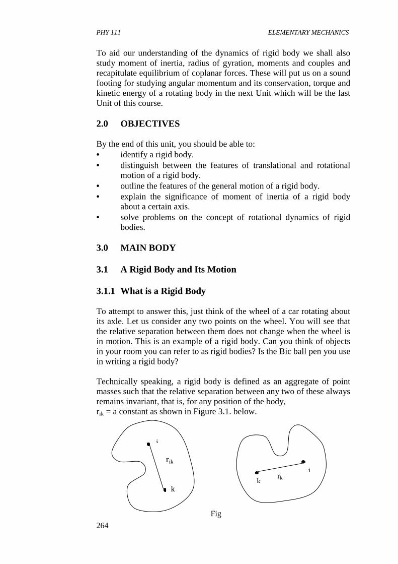
PHY 111 ELEMENTARY MECHANICS
264
To aid our understanding of the dynamics of rigid body we shall also study moment of inertia, radius of gyration, moments and couples and recapitulate equilibrium of coplanar forces. These will put us on a sound footing for studying angular momentum and its conservation, torque and kinetic energy of a rotating body in the next Unit which will be the last Unit of this course. 2.0 OBJECTIVES By the end of this unit, you should be able to: • identify a rigid body. • distinguish between the features of translational and rotational
motion of a rigid body. • outline the features of the general motion of a rigid body. • explain the significance of moment of inertia of a rigid body
about a certain axis. • solve problems on the concept of rotational dynamics of rigid
bodies. 3.0 MAIN BODY 3.1 A Rigid Body and Its Motion 3.1.1 What is a Rigid Body To attempt to answer this, just think of the wheel of a car rotating about its axle. Let us consider any two points on the wheel. You will see that the relative separation between them does not change when the wheel is in motion. This is an example of a rigid body. Can you think of objects in your room you can refer to as rigid bodies? Is the Bic ball pen you use in writing a rigid body? Technically speaking, a rigid body is defined as an aggregate of point masses such that the relative separation between any two of these always remains invariant, that is, for any position of the body, rik = a constant as shown in Figure 3.1. below.
Fig 3.1
i
rik
k k
rk
i
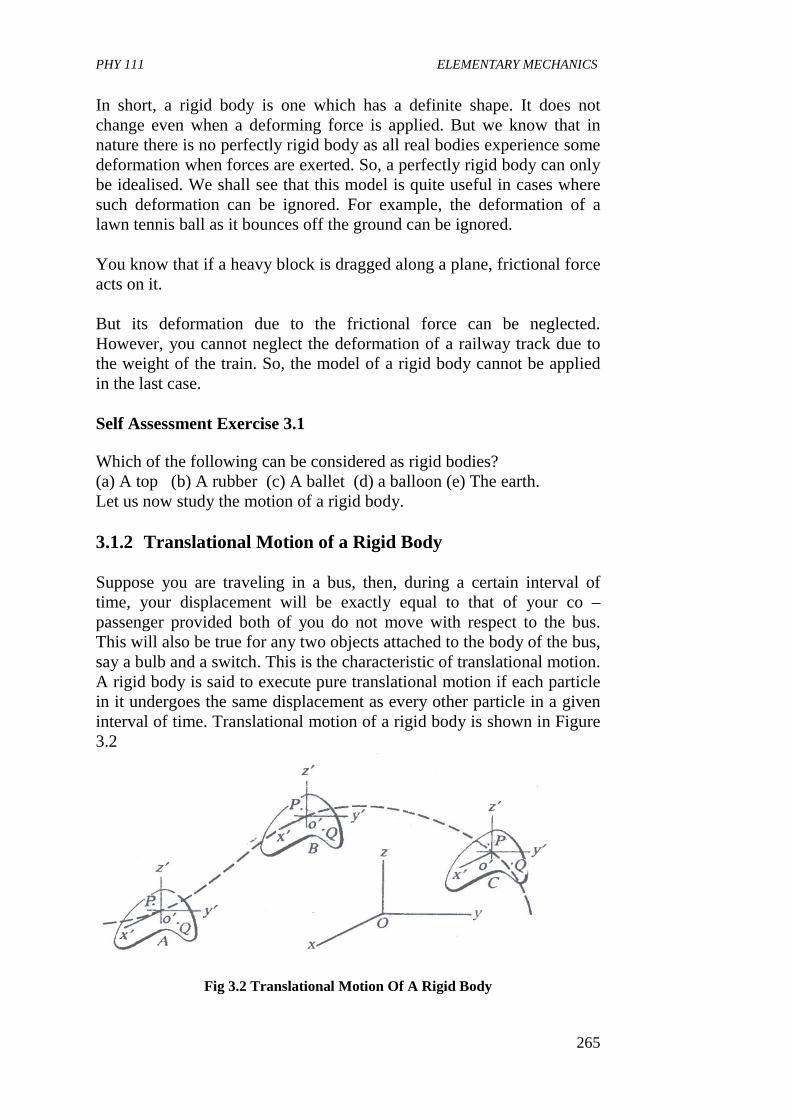
PHY 111 ELEMENTARY MECHANICS
265
In short, a rigid body is one which has a definite shape. It does not change even when a deforming force is applied. But we know that in nature there is no perfectly rigid body as all real bodies experience some deformation when forces are exerted. So, a perfectly rigid body can only be idealised. We shall see that this model is quite useful in cases where such deformation can be ignored. For example, the deformation of a lawn tennis ball as it bounces off the ground can be ignored. You know that if a heavy block is dragged along a plane, frictional force acts on it. But its deformation due to the frictional force can be neglected. However, you cannot neglect the deformation of a railway track due to the weight of the train. So, the model of a rigid body cannot be applied in the last case. Self Assessment Exercise 3.1 Which of the following can be considered as rigid bodies? (a) A top (b) A rubber (c) A ballet (d) a balloon (e) The earth. Let us now study the motion of a rigid body. 3.1.2 Translational Motion of a Rigid Body Suppose you are traveling in a bus, then, during a certain interval of time, your displacement will be exactly equal to that of your co – passenger provided both of you do not move with respect to the bus. This will also be true for any two objects attached to the body of the bus, say a bulb and a switch. This is the characteristic of translational motion. A rigid body is said to execute pure translational motion if each particle in it undergoes the same displacement as every other particle in a given interval of time. Translational motion of a rigid body is shown in Figure 3.2
Fig 3.2 Translational Motion Of A Rigid Body
PHY 111 ELEMENTARY MECHANICS
266
You must have noticed that the path taken is not necessarily a straight line. The magnitudes of the distance between P O1 and Q should always be the same. Self Assessment Exercise 3.2 Give two examples of translational motion Now that you have worked out exercise 3.2 you can see that if we are able to describe the motion of a single particle in the body, we can describe the motion of the body as a whole. We have done this exercise a number of times before. However, you may like to consolidate your understanding by working out the following exercise. Self Assessment Exercise 3.3 A rigid body of mass M is executing a translational motion under the influence of an external force Fe. Suggest a suitable differential equation of motion of the body. What does the answer to exercise 3.3 signify? We know that the relative separation between any two points of a rigid body does not change. That is,
So all the points follow the same trajectory on as the centre of mass. Hence for studying translational motion, the body may be treated as a particle of mass M located at its centre of mass (C.M). You may recall that we had treated the sun and a planet as particles in Units 11, 12, and 13. They were treated as particles as their sizes are negligible compared to the distances between them and also because the shapes of these bodies were insignificant. But here we are considering a rigid body as a particle for another reason as explained above. Thus we can represent the translational motion of its C.M. It becomes easier to describe the translational motion in this way. Recall that we had applied the above idea when we studied cases like a body falling or sliding down an inclined plane in Unit 14. Let us now discuss the rotational motion of a rigid body. 3.1.3 Rotational Motion of a Rigid Body Let us consider the motion of the earth. Every point on it moves in a circle (the corresponding latitude), the centres of which lie on the polar axis. Such a motion is an example of a rotational motion. A rigid body is said to execute rotational motion if all the particles in it move in circles,
Ο=dt
drik
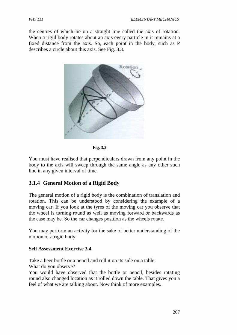
PHY 111 ELEMENTARY MECHANICS
267
the centres of which lie on a straight line called the axis of rotation. When a rigid body rotates about an axis every particle in it remains at a fixed distance from the axis. So, each point in the body, such as P describes a circle about this axis. See Fig. 3.3.
Fig. 3.3
You must have realised that perpendiculars drawn from any point in the body to the axis will sweep through the same angle as any other such line in any given interval of time. 3.1.4 General Motion of a Rigid Body The general motion of a rigid body is the combination of translation and rotation. This can be understood by considering the example of a moving car. If you look at the tyres of the moving car you observe that the wheel is turning round as well as moving forward or backwards as the case may be. So the car changes position as the wheels rotate. You may perform an activity for the sake of better understanding of the motion of a rigid body. Self Assessment Exercise 3.4 Take a beer bottle or a pencil and roll it on its side on a table. What do you observe? You would have observed that the bottle or pencil, besides rotating round also changed location as it rolled down the table. That gives you a feel of what we are talking about. Now think of more examples.
PHY 111 ELEMENTARY MECHANICS
268
We shall now move on to study moment of inertia because it will play an important role in the determination of the angular momentum of a rotating rigid body. In dealing with circular motions, we have all these while considered particles in motion with the result that a particle revolved round a circle of the same radius. But now we are going to consider the rotation of a system of connected “particles” moving in circles of different radii. The spatial distribution of the mass of the body affects the behaviour of the body. We note also that the mass of a body is a measure of its in – built resistance to any change of linear motion. Thus we say that mass measures inertia. The corresponding property for rotational motion is called the moment of inertia. The more difficult it is to change the velocity of a body rotating about a particular axis, the greater is its moment of inertia about that axis. From experiments, it was seen that a wheel with most of its mass concentrated in the rim is more difficult to start and stop than a uniform disc of equal mass - spread rotating about the same axis. The former has a greater moment of inertia. Take note of this important point – that moment of inertia is a property of a body rotating about a particular axis. If the axis changes, the value of the moment of inertia also changes. 3.2 Moment of Inertia We need now to measure the moment of inertia which takes into account the mass distribution of the body about the axis of rotation and which plays a role in rotational motion. This is analogous to that played by mass in linear motion. Consider a rigid body rotating about a fixed axis through O with constant angular Velocity ω, as shown in Figure (3.4) below. A particle A, of mass m1, at a distance r1 from O describes its own circular path and v1 is its linear velocity along the tangent of the path at the instant shown, then v1 = r1ω 3.1 and
2.3
2
12
1
221
211
ωrm
vmAofEnergyKineticthe
=
=
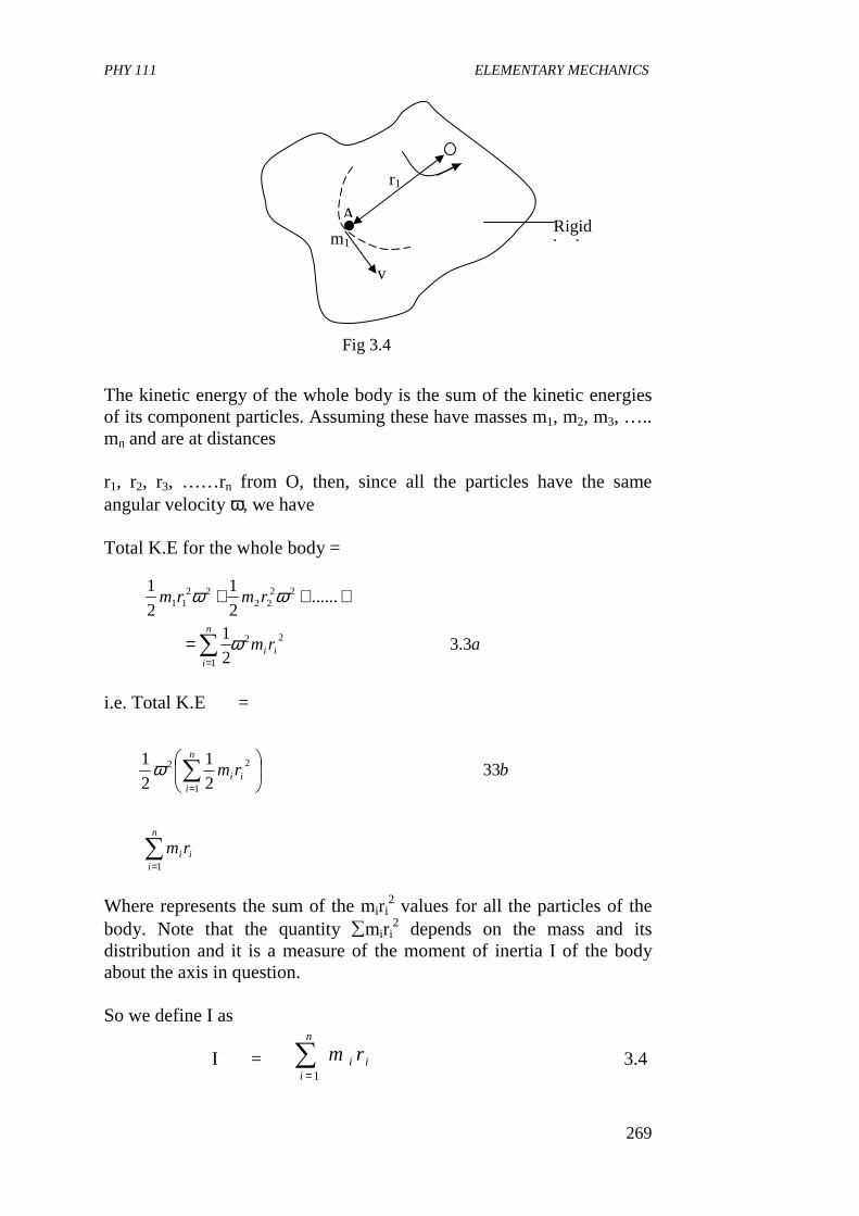
PHY 111 ELEMENTARY MECHANICS
269
The kinetic energy of the whole body is the sum of the kinetic energies of its component particles. Assuming these have masses m1, m2, m3, ….. mn and are at distances r1, r2, r3, ……rn from O, then, since all the particles have the same angular velocity ω, we have Total K.E for the whole body =
i.e. Total K.E =
Where represents the sum of the miri
2 values for all the particles of the body. Note that the quantity ∑miri
2 depends on the mass and its distribution and it is a measure of the moment of inertia I of the body about the axis in question. So we define I as I = 3.4
arm
rmrm
ii
n
i
3.32
1
......2
1
2
1
22
1
2222
2211
ω
ωω
∑=
=
+++
brmn
iii 33
2
1
2
1
1
22
∑
=
ω
i
n
ii rm∑
= 1
Rigid body
v
m1
A
r1
Fig 3.4
i
n
ii rm∑
=1

PHY 111 ELEMENTARY MECHANICS
270
We can then write the K.E. as K.E of body =
Comparing this with the kinetic energy for linear motion ½ mv2 we see that mass m is replaced by the moment of inertia I and the velocity v is replaced by the angular velocity ω. The Unit of moment of inertia I is kg m2. Values of I for regular shapes of bodies can be determined using calculus. For example, That for a uniform rod of mass m and length L about an axis through its centre is mL2/12. When the rotation is about an axis at one of its ends it becomes mL2/13. Fig. 3.5 say Do you think rotational kinetic energy ½ Iω2 is a new kind of energy? Not at all. It is simply the sum of the linear kinetic energies of all the particles making up the body, and is a convenient way of representing the K.E of a rotating rigid body. The mass of a flywheel is concentrated in the rim, thereby giving it a large moment of inertia. When it rotates, it possesses large K.E. This explains why it is able to keep an engine (e.g in a car) running at a fairly steady speed despite the fact that energy is applied only intermittently to it. You may do well to know that some toy cars have a small lead flywheel which is set into rapid rotation by a brief push across a solid surface. The K.E of the flywheel will then keep the car in motion for some distance.
5.32
1 2ωΙ
axis of rotation
L I = ½ ml2
(ii)
L axis of rotation
I = ml2/12
(i)
Fig 3.5

PHY 111 ELEMENTARY MECHANICS
271
Values of moments of inertia for other regular shapes are shown in Figure 3.6
Fig 3.6 Example: Three small bodies, which can be considered as particles are connected by light rigid rods, as in the Figure 3.7 below. What is the moment of inertia of the system (a) about an axis through A, perpendicular to the plane of the diagram? (b) about an axis coinciding with the rod BC? Solution: Since particle A lies on the axis, it does not contribute to the moment of inertia because the distance from the axis of rotation is zero.
0.5m
B 0.1kg
0.3kg
C 0.2kg 0.4m
Fig 3.7
A 0.3kg
PHY 111 ELEMENTARY MECHANICS
272
Hence, I = ∑ m r2 = (0.1kg) (0.5m)2 + (0.2kg) (0.4m)2 = 0.057kg m2 (b) The particles B and C both lie in the axis and so they too contribute nothing Hence, I = ∑ m r2 = (0.3kg) (0.4m)2 = 0.048 kg m2 Self Assessment Exercise 3.5 If in Figure 3.4 above the body rotates about an axis through A and perpendicular to the plane of the diagram, with an angular velocity ω = 4 rad s1, what is the rotational kinetic energy? Solution.
3.2.1 Raduis of Gyration No matter what the shape of a body is, it is always possible to find a radial distance from any given axis at which the mass of the body could be concentrated without changing the moment of inertia of the body about that axis. This distance is known as the radius of gyration of the body about the given axis. It is denoted by K. So if mass m of the body actually were concentrated at this distance, the moment of inertia would be that of a particle of mass m at a distance k from an axis, or mk2. But we see that this is equal to actual moment of inertia I, therefore mk2 = I 3.6 Self Assessment Exercise 3.6 What is the radius of gyration of a slender rod of mass m and length L about an axis perpendicular to its length and passing through the centre?
J
radskgIEK
456.0
)4)(057.0(2
1
2
1.. 12
=
== −ω

PHY 111 ELEMENTARY MECHANICS
273
Solution: The moment of inertia about an axis through the centre is I = mL2 / 12 Therefore,
K0 = We therefore note that the radius of gyration, like the moment of inertia depends on the location of the axis. 3.2.2 The Dumbbell. The simplest rotating object that we can contemplate is a dumbbell. It consists of two point masses m1 and m2 connected by a massless rigid rod of length L as shown in Figure 3.8 below. Let the total mass M be m1 + m2. Positioning mass m1 at the origin of the x – axis and man m2 at x = L. it could be shown that the centre of mass is at x where
If we consider the case in which the axis of rotation goes through the centre of mass (C.M) (i.e through point x = m2 L/M, then the axis is taken perpendicular to the rod. So, measuring from the C.M, the coordinates of m1 and m2 will be –m2 L/M and L- (m2/m) = m1L/M respectively.
L
L
mmL
289.0
32/
12/2
==
( )( ) ( )( )
M
Lm
mm
Lmmx
2
21
21 0
=
++=
m1
x = L
m2
c.m
x = 0 x = m2/m1+m2
Fig 3.8
x
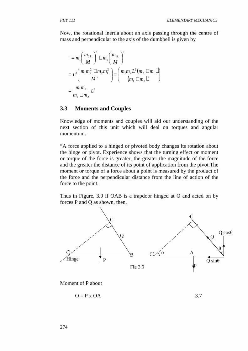
PHY 111 ELEMENTARY MECHANICS
274
Now, the rotational inertia about an axis passing through the centre of mass and perpendicular to the axis of the dumbbell is given by
3.3 Moments and Couples Knowledge of moments and couples will aid our understanding of the next section of this unit which will deal on torques and angular momentum. “A force applied to a hinged or pivoted body changes its rotation about the hinge or pivot. Experience shows that the turning effect or moment or torque of the force is greater, the greater the magnitude of the force and the greater the distance of its point of application from the pivot.The moment or torque of a force about a point is measured by the product of the force and the perpendicular distance from the line of action of the force to the point. Thus in Figure, 3.9 if OAB is a trapdoor hinged at O and acted on by forces P and Q as shown, then, Moment of P about
O = P x OA 3.7
( )( )
2
21
21
221
122
212
212
2212
2
12
2
21
Lmm
mm
mm
mmLmm
M
mmmmL
M
mm
M
mm LL
+=
++
=
+=
+
=Ι
Hinge p B
Q
C
Fig 3.9
C
o θ
Q Q cosθ
Q sinθ p
A
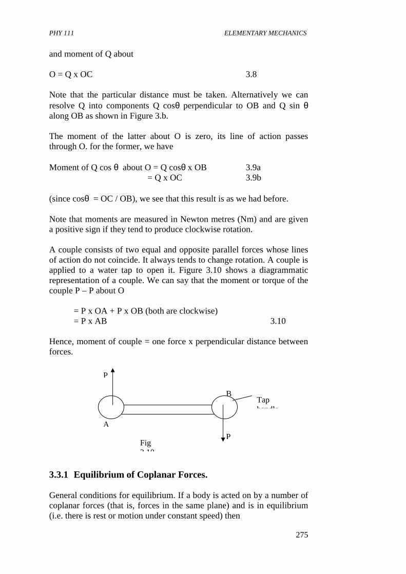
PHY 111 ELEMENTARY MECHANICS
275
and moment of Q about O = Q x OC 3.8 Note that the particular distance must be taken. Alternatively we can resolve Q into components Q cosθ perpendicular to OB and Q sin θ along OB as shown in Figure 3.b. The moment of the latter about O is zero, its line of action passes through O. for the former, we have Moment of Q cos θ about O = Q cosθ x OB 3.9a = Q x OC 3.9b (since cosθ = OC / OB), we see that this result is as we had before. Note that moments are measured in Newton metres (Nm) and are given a positive sign if they tend to produce clockwise rotation. A couple consists of two equal and opposite parallel forces whose lines of action do not coincide. It always tends to change rotation. A couple is applied to a water tap to open it. Figure 3.10 shows a diagrammatic representation of a couple. We can say that the moment or torque of the couple P – P about O = P x OA + P x OB (both are clockwise) = P x AB 3.10 Hence, moment of couple = one force x perpendicular distance between forces. 3.3.1 Equilibrium of Coplanar Forces. General conditions for equilibrium. If a body is acted on by a number of coplanar forces (that is, forces in the same plane) and is in equilibrium (i.e. there is rest or motion under constant speed) then
P
P
A
B Tap handle
Fig 3.10
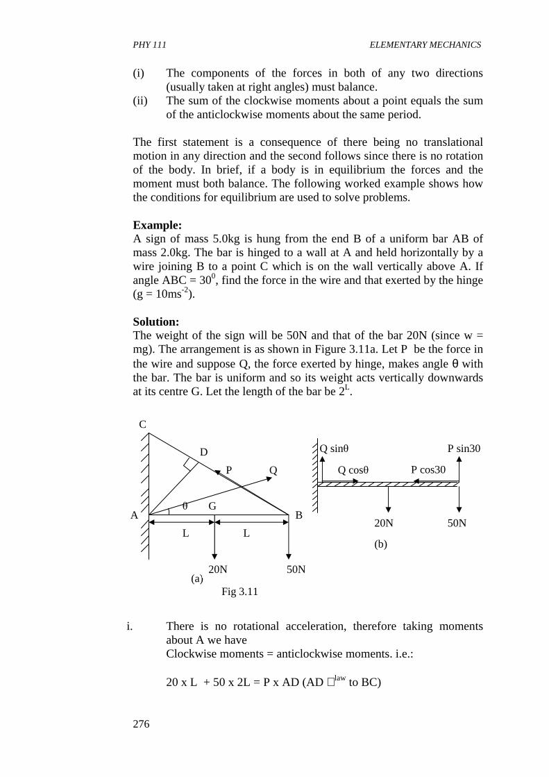
PHY 111 ELEMENTARY MECHANICS
276
(i) The components of the forces in both of any two directions (usually taken at right angles) must balance.
(ii) The sum of the clockwise moments about a point equals the sum of the anticlockwise moments about the same period.
The first statement is a consequence of there being no translational motion in any direction and the second follows since there is no rotation of the body. In brief, if a body is in equilibrium the forces and the moment must both balance. The following worked example shows how the conditions for equilibrium are used to solve problems. Example: A sign of mass 5.0kg is hung from the end B of a uniform bar AB of mass 2.0kg. The bar is hinged to a wall at A and held horizontally by a wire joining B to a point C which is on the wall vertically above A. If angle ABC = 300, find the force in the wire and that exerted by the hinge (g = 10ms-2). Solution: The weight of the sign will be 50N and that of the bar 20N (since w = mg). The arrangement is as shown in Figure 3.11a. Let P be the force in the wire and suppose Q, the force exerted by hinge, makes angle θ with the bar. The bar is uniform and so its weight acts vertically downwards at its centre G. Let the length of the bar be 2L.
i. There is no rotational acceleration, therefore taking moments about A we have Clockwise moments = anticlockwise moments. i.e.: 20 x L + 50 x 2L = P x AD (AD ⊥law to BC)
G θ
D
P Q
B
(a) Fig 3.11
20N 50N
L
A
C
L
P sin30
P cos30
Q sinθ
Q cosθ
20N 50N
(b)
PHY 111 ELEMENTARY MECHANICS
277
∴120L = P x AB sin 30 since AB
AD=30
= P x 2L x 0.5 ∴P = 1.2 x 10² N
Note: by taking moments about A there is no need to consider Q since it passes through A and so has zero moment.
ii. There is no translational acceleration, therefore the vertical components (and force) must balance, likewise the horizontal components. Hence resolving Q and P into vertical and horizontal components (which now replace them) shown in Fig. 11b, we have : Vertically
Q sin θ + P sin 30 = 20 + 50 ∴Q sin θ = 70 - 120
Q sin θ = 10 (1)
Horizontally. Q Cos θ = P cos 30 = )2
3(120
Dividing (1) by (2)
∴θ = 5.50 Squaring (1) and (2) and adding Q2 (sin2 θ + cos2θ ) = 100 + 10800 ∴Q = 10900 (sin2 θ + cos2θ = 1) and Q = 1.0(4) x 102 N. Structures: Forces act at a joint in many structures and if these are in equilibrium then so too are the joints. The joint O in the bridge structure of Fig. 3.12 is in equilibrium under the action of forces P and Q exerted by girders and the normal force S exerted by the bride support at O. The
1 2
( )2360sin =∴ θϕ
( )360/10tan =θ
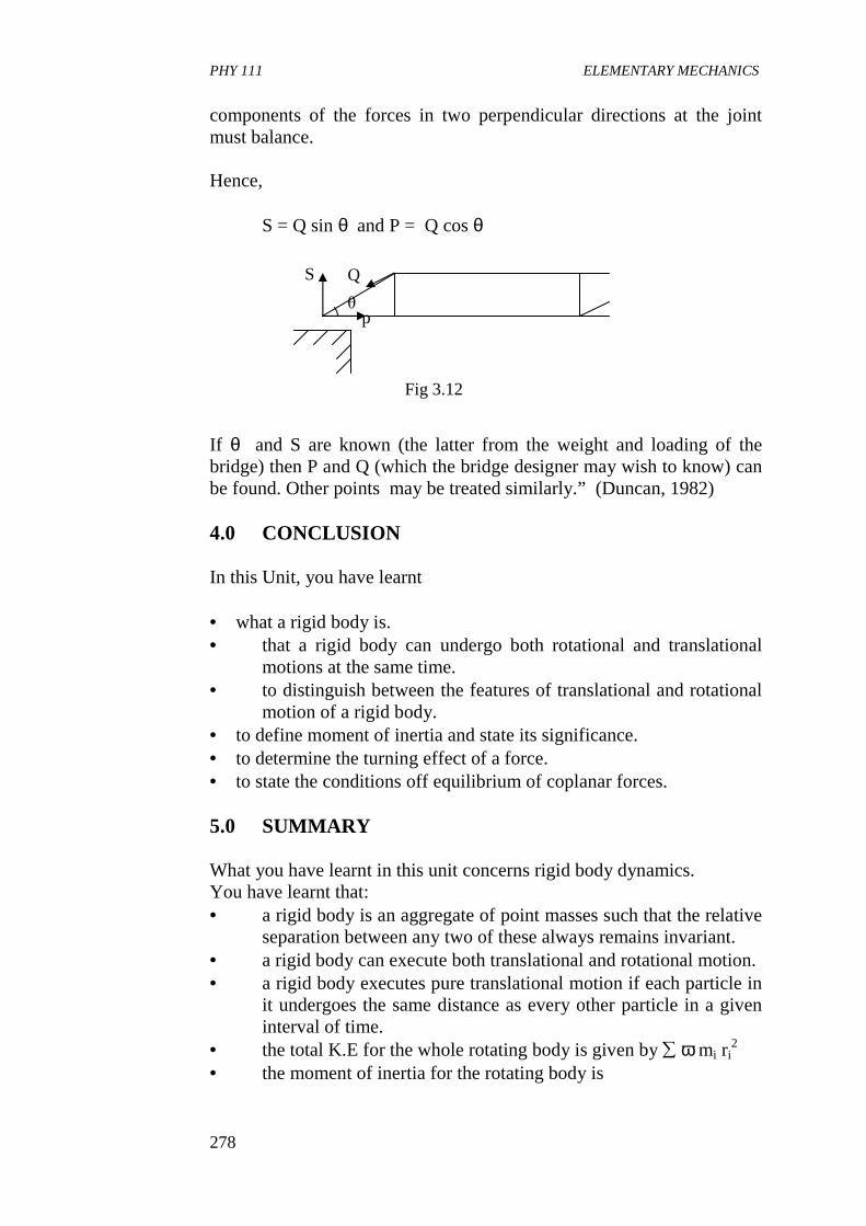
PHY 111 ELEMENTARY MECHANICS
278
components of the forces in two perpendicular directions at the joint must balance. Hence, S = Q sin θ and P = Q cos θ If θ and S are known (the latter from the weight and loading of the bridge) then P and Q (which the bridge designer may wish to know) can be found. Other points may be treated similarly.” (Duncan, 1982) 4.0 CONCLUSION In this Unit, you have learnt • what a rigid body is. • that a rigid body can undergo both rotational and translational
motions at the same time. • to distinguish between the features of translational and rotational
motion of a rigid body. • to define moment of inertia and state its significance. • to determine the turning effect of a force. • to state the conditions off equilibrium of coplanar forces. 5.0 SUMMARY What you have learnt in this unit concerns rigid body dynamics. You have learnt that: • a rigid body is an aggregate of point masses such that the relative
separation between any two of these always remains invariant. • a rigid body can execute both translational and rotational motion. • a rigid body executes pure translational motion if each particle in
it undergoes the same distance as every other particle in a given interval of time.
• the total K.E for the whole rotating body is given by ∑ ω mi ri2
• the moment of inertia for the rotating body is
Q
p θ
S
Fig 3.12
PHY 111 ELEMENTARY MECHANICS
279
where the symbols have their usual meanings.
• the moment or torque of a force about a point is measured by the product of the force and the perpendicular distance from the line of action of the force to the point.
• a couple consists of two equal and opposite parallel forces whose lines of action do not coincide. It always tends to change rotation.
• if a body is acted on by a number of coplanar forces then for equilibrium (i) The components of the forces in both of any two
directions must balance. (ii) The sum of the clockwise moments about a point equals
the sum of the anticlockwise moments about the same point.
6.0 TUTOR MARKED ASSIGNMENT 1. Two point-like masses are placed on a massless rod that is 1.5m
long. The masses are placed as follows 1.6kg at the left end and 1.8kg 1.2m from the left end. (a) What is the location of the centre of mass? (b) By moving the 1.8kg mass, can you arrange to have the
centre of mass in the middle of the rod? 2. A pulley is rotating at the rate of 32 rev/min. A motor speeds up
the wheel so that 30.0s later it is turning at 82 rev/min. (a) What is the average angular acceleration in radians per
sec? (b) How far will a point 0.30cm from the centre of the pulley
travelled during the acceleration period, assuming that the acceleration is uniform?
3. The flywheel of a gasoline engine is required to give up 300 J of
kinetic energy while its angular velocity decreased from 600 rev min-1 to 540 rev.min-1. What moment of inertia is required?
7.0 REFERENCES AND FURTHER READING Sears F.W, Zemansky M.W and Young H.D (1975) College Physics,(
4th Ed). Addison – Wesley Publ. Co. Reading. U.K. Fishbane P.M, Gasiorowicz, S and Thronton S.T, (1996). Physics For
Scientists and Engineers, 2nd Ed., Prentice Hall Pub,New Jersey
1 2
∑=
=Ιn
iii rm
1
2
PHY 111 ELEMENTARY MECHANICS
280
Nelkon M. and Parker P (1970) Advanced Level Physics Heinemann
Educational Books Ltd; London. Indira Ghandi National Open University School Of Sciences, PHE – 0l,
Elementary Mechanics Systems Of Particles
PHY 111 ELEMENTARY MECHANICS
281
UNIT 5 RIGID BODY DYNAMICS 11 CONTENTS 1.0 Introduction 2.0 Objectives 3.0 Main Body
3.1 Rotational Dynamics of A Rigid Body 3.1.1 Torque 3.1.2 Angular Momentum
3.1.2.1 Definition 3.1.3 Conservation of Angular Momentum And Its
Application 3.1.4 Experiment in Conservation of Angular Momentum 3.1.5 The Top and the Gyroscope
4.0 Conclusion 5.0 Summary 6.0 Tutor Marked Assignments (TMAs) and Marking Scheme 7.0 References and Further Reading 1.0: INTRODUCTION This unit is a continuation of the preceding unit; so, most of the introductory remarks are covered there. Additionally, in this Unit you will study about the force that causes rotation; angular momentum and its conservation. We shall also see real physical systems, such as divers and figure skaters executing complex maneuvers, yet they are not rigid bodies showing that angular momentum and its conservation are very useful concepts. More examples of the applications of angular momentum and its conservation abound though they are beyond the scope of this course. You will definitely study about some of them in your future years. We shall wrap up this course with the introduction of the concept of the top or gyroscope. 2.0 OBJECTIVES By the end of this unit, you should be able to: • state what causes rotation of rigid bodies. • explain the concept of moment of a couple. • define the angular momentum of a rigid body. • apply the law of conservation of angular momentum. • solve problems based on the concept of rotational dynamics of
rigid bodies.
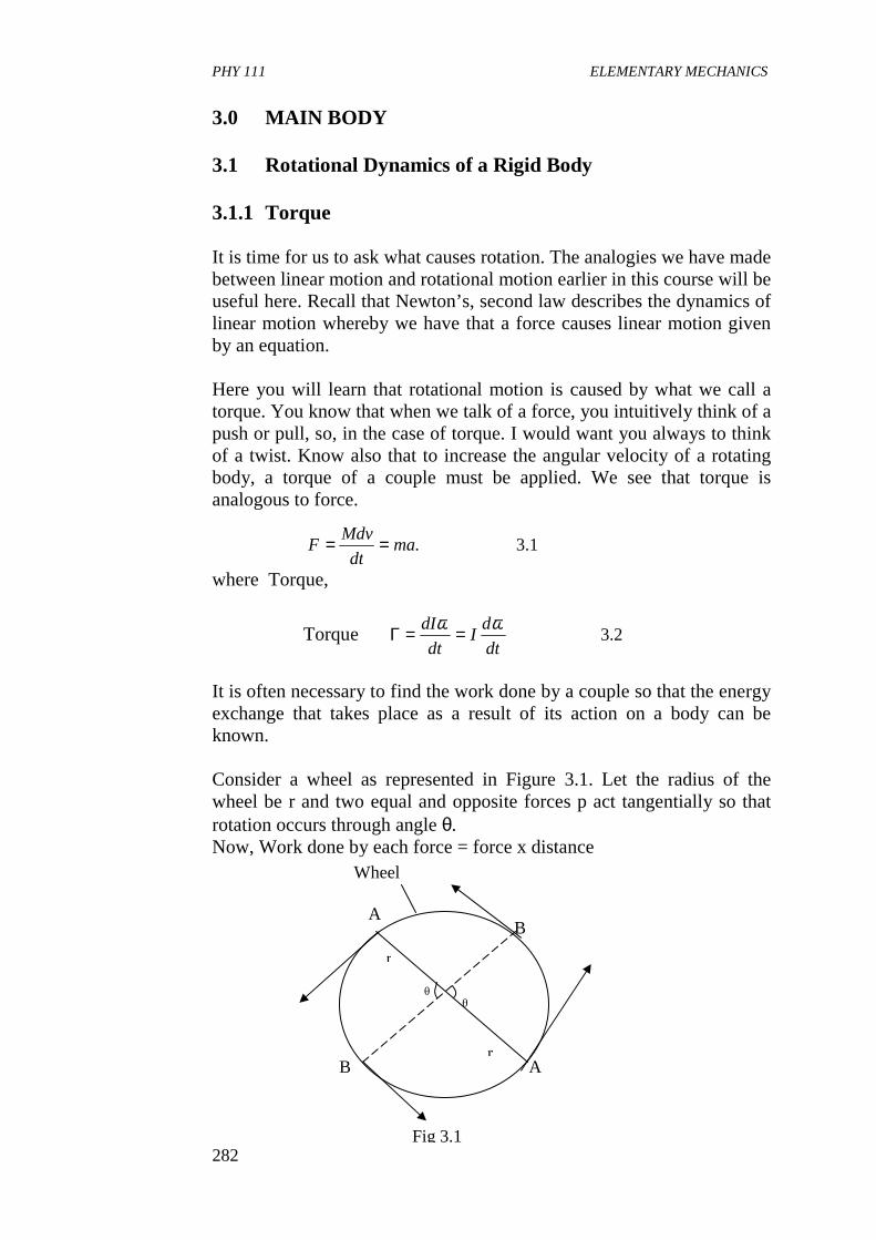
PHY 111 ELEMENTARY MECHANICS
282
3.0 MAIN BODY 3.1 Rotational Dynamics of a Rigid Body 3.1.1 Torque It is time for us to ask what causes rotation. The analogies we have made between linear motion and rotational motion earlier in this course will be useful here. Recall that Newton’s, second law describes the dynamics of linear motion whereby we have that a force causes linear motion given by an equation. Here you will learn that rotational motion is caused by what we call a torque. You know that when we talk of a force, you intuitively think of a push or pull, so, in the case of torque. I would want you always to think of a twist. Know also that to increase the angular velocity of a rotating body, a torque of a couple must be applied. We see that torque is analogous to force.
where Torque,
Torque 2.3dt
dI
dt
dI ωω ==Γ
It is often necessary to find the work done by a couple so that the energy exchange that takes place as a result of its action on a body can be known. Consider a wheel as represented in Figure 3.1. Let the radius of the wheel be r and two equal and opposite forces p act tangentially so that rotation occurs through angle θ. Now, Work done by each force = force x distance
1.3.madt
MdvF ==
Fig 3.1
Wheel
B A
B A
r
θ θ
r
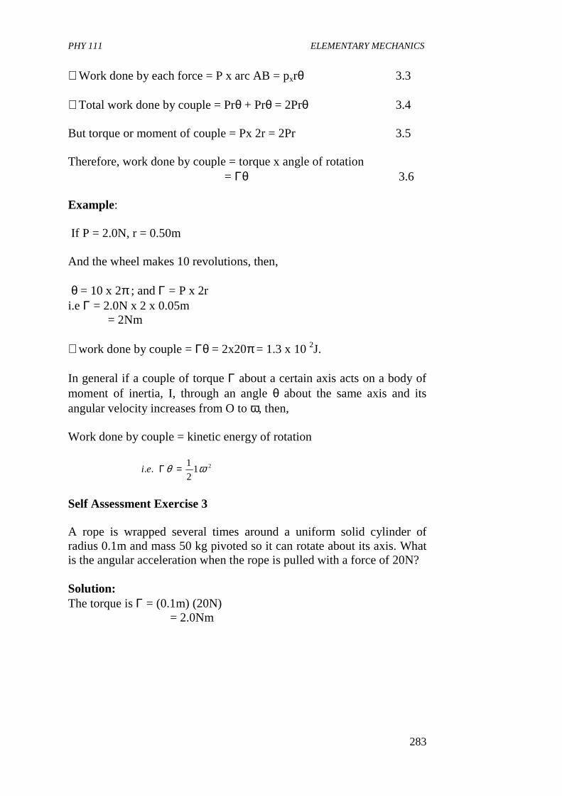
PHY 111 ELEMENTARY MECHANICS
283
∴Work done by each force = P x arc AB = pxrθ 3.3 ∴Total work done by couple = Prθ + Prθ = 2Prθ 3.4 But torque or moment of couple = Px 2r = 2Pr 3.5 Therefore, work done by couple = torque x angle of rotation = Γθ 3.6 Example: If P = 2.0N, r = 0.50m And the wheel makes 10 revolutions, then, θ = 10 x 2π ; and Γ = P x 2r i.e Γ = 2.0N x 2 x 0.05m = 2Nm ∴work done by couple = Γθ = 2x20π = 1.3 x 10 2J. In general if a couple of torque Γ about a certain axis acts on a body of moment of inertia, I, through an angle θ about the same axis and its angular velocity increases from O to ω, then, Work done by couple = kinetic energy of rotation
Self Assessment Exercise 3 A rope is wrapped several times around a uniform solid cylinder of radius 0.1m and mass 50 kg pivoted so it can rotate about its axis. What is the angular acceleration when the rope is pulled with a force of 20N? Solution: The torque is Γ = (0.1m) (20N) = 2.0Nm
212
1.. ωθ =Γei
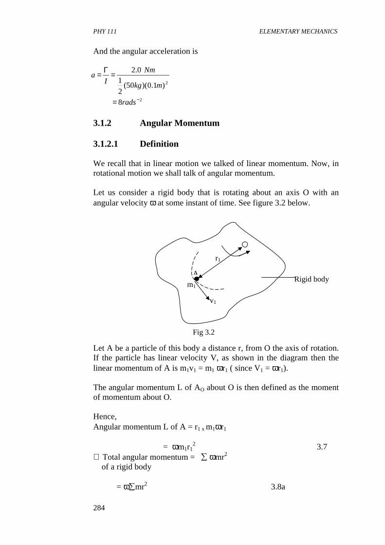
PHY 111 ELEMENTARY MECHANICS
284
And the angular acceleration is
3.1.2 Angular Momentum 3.1.2.1 Definition We recall that in linear motion we talked of linear momentum. Now, in rotational motion we shall talk of angular momentum. Let us consider a rigid body that is rotating about an axis O with an angular velocity ω at some instant of time. See figure 3.2 below. Let A be a particle of this body a distance r, from O the axis of rotation. If the particle has linear velocity V, as shown in the diagram then the linear momentum of A is m1v1 = m1 ωr1 ( since V1 = ωr1). The angular momentum L of AO about O is then defined as the moment of momentum about O. Hence, Angular momentum L of A = r1 x m1ωr1
= ωm1r12 3.7
∴ Total angular momentum = ∑ ωmr2 of a rigid body
= ω∑mr2 3.8a
2
2
8
)1.0)(50(2
10.2
−=
=Γ=
rads
mkg
Nm
Ia
Rigid body
v1
m1 A
r1
Fig 3.2
PHY 111 ELEMENTARY MECHANICS
285
∴ L = 1ω 3.8b Where we recognize 1 as the moment of inertia of the body about O. It is thus evident that angular momentum is the analogue of linear momentum (mv) where 1 is equivalent to mass m and ω replaces velocity V. We can then state Newton’s second law of rotational dynamics as follows. A body rotates when it is acted on by a couple. ∴Γ = 1α 3.9 where Γ is the torque of moment of the couple causing rotational acceleration α. In terms of momentum we have that Torque = rate of change of angular momentum i.e
This is analogons to force which is the rate of change of linear momentum
3.1.3 Conservation Of Angular Momentum and Its
Applications. Angular momentum is a vector that points in the same direction as ω. For uniform rotational motion about an axis, the angular momentum does not change in either magnitude or direction. Just as in the case for linear momentum, angular momentum is independent of time for a system on which there is no torque due to external forces. Note that it is possible that the external torque is zero even when the external force is not zero. This will depend on where the external force is applied and on its direction. Similarly, a net torque could exist when a net force is zero. When the net torque is zero, the angular momentum is independent of time and is conserved. For rigid bodies, the rotational inertia is constant, and the conservation of angular momentum means that the angular velocity is constant in time. When the rotational inertia can vary because
10.3dt
dl
dt
dI ==Γ ω
11.3dt
mdvF =
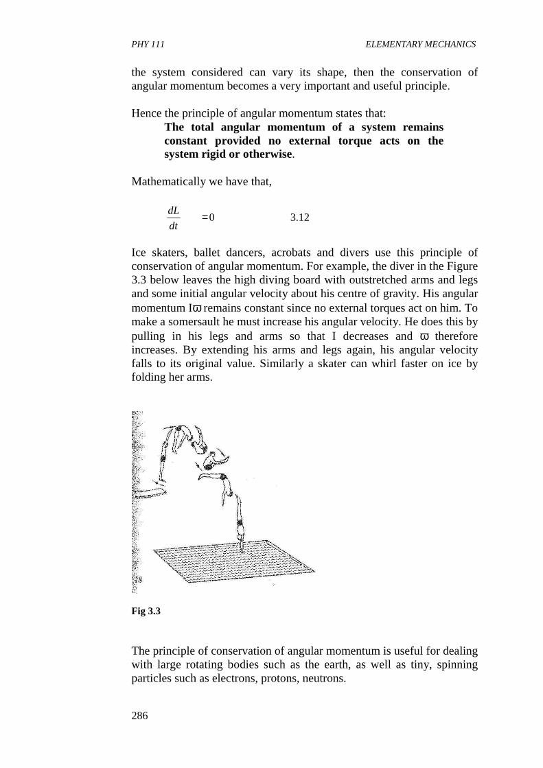
PHY 111 ELEMENTARY MECHANICS
286
the system considered can vary its shape, then the conservation of angular momentum becomes a very important and useful principle. Hence the principle of angular momentum states that:
The total angular momentum of a system remains constant provided no external torque acts on the system rigid or otherwise.
Mathematically we have that,
Ice skaters, ballet dancers, acrobats and divers use this principle of conservation of angular momentum. For example, the diver in the Figure 3.3 below leaves the high diving board with outstretched arms and legs and some initial angular velocity about his centre of gravity. His angular momentum Iω remains constant since no external torques act on him. To make a somersault he must increase his angular velocity. He does this by pulling in his legs and arms so that I decreases and ω therefore increases. By extending his arms and legs again, his angular velocity falls to its original value. Similarly a skater can whirl faster on ice by folding her arms.
Fig 3.3 The principle of conservation of angular momentum is useful for dealing with large rotating bodies such as the earth, as well as tiny, spinning particles such as electrons, protons, neutrons.
12.30=dt
dL
PHY 111 ELEMENTARY MECHANICS
287
The earth is an object which rotates about an axis passing through its geographic north and south poles with a period of 1 day . If it is struck by meteorites, then since action and reaction are equal, no external couple acts on the earth and meteorites. Their total angular momentum is thus conserved. Neglecting the angular momentum of the meteorites about the earth’s axis before collision compared with that of the earth. Then, Angular momentum of earth plus meteorites after collision = angular momentum of earth before collision. Since the effective mass of the earth has increased after collision the moment of inertia has also increased. Hence, the earth will slow up slightly. Similarly, when a mass of object is dropped gently on to a turntable rotating freely at a steady speed, the conservation of angular momentum leads to a reduction in the speed of the turntable. Example: Calculate the angular momentum of earth’s motion about its axis of rotation given that earth’s mass is 6 x 1024kg and its radius is 6.4 x 10⁶
m. Assume that the mass density is uniform. Solution : arth makes one revolution about its axis in 24h. Thus, its period of rotation is
Now since the rotational inertia of a uniform sphere is
15103.7
400,86
28.62
,
86400
sec60
1
min6024
−−×=
=Τ
=
=
××=Τ
srad
s
rad
Hence
smh
h
πω
( )( )( )
( )( )1233
5237
237
2624
2
.107
103.7.1010
.1010
104.61064.0
5
2
−
−
×=
××==
×=××=
=Τ
smkg
radsmkgIL
mkg
mkg
MR
ω
PHY 111 ELEMENTARY MECHANICS
288
We notice that our calculated value of I is some 20 percent larger than the correct value of 7.9 x 1037kg.m2. Why is it so Self Assessment Exercise 4 The earth is suddenly condensed so that it’s radius becomes half of its usual value without its mass being changed. How will the period of daily rotation change? Solution: of (b) from the principle of conservation of angular momentum, we get I1ω1 = I2 ω2.
So the time period of daily rotation will become 6h. 3.1.4 Experiment on Conservation Of Angular Momentum. A simple experiment to illustrate the principle of the conservation of angular momentum is illustrated below in Figure 3.4
earthofrotationdailyofperiodstimechangedandusualtheareTandTwhere
Tand
TBut
or
RMMR
RRand
MRIMRIHere
22
22
11
12
2
21
121
12
222
211
22
445
2
5
2
2
5
2,
5
2
πωπω
ωω
ωω
==
=
=∴
=
==
h
hTT
64
24
41
2
=
==∴
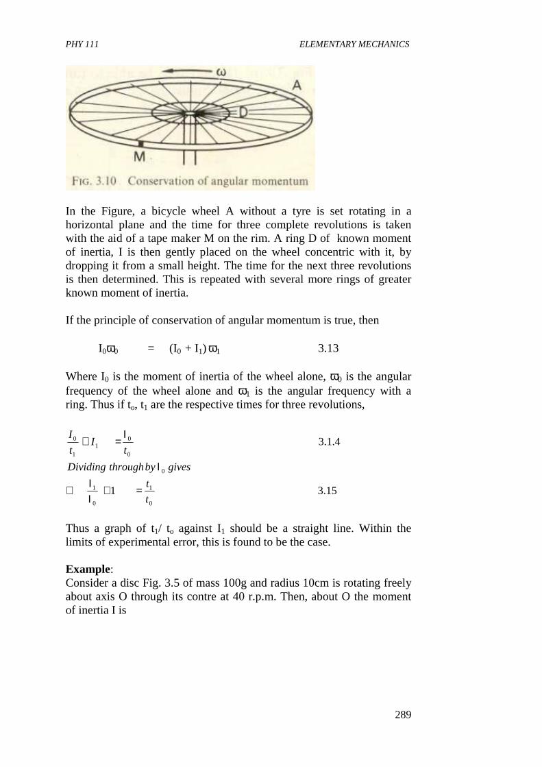
PHY 111 ELEMENTARY MECHANICS
289
In the Figure, a bicycle wheel A without a tyre is set rotating in a horizontal plane and the time for three complete revolutions is taken with the aid of a tape maker M on the rim. A ring D of known moment of inertia, I is then gently placed on the wheel concentric with it, by dropping it from a small height. The time for the next three revolutions is then determined. This is repeated with several more rings of greater known moment of inertia. If the principle of conservation of angular momentum is true, then
I0ω0 = (I0 + I1) ω1 3.13
Where I0 is the moment of inertia of the wheel alone, ω0 is the angular frequency of the wheel alone and ω1 is the angular frequency with a ring. Thus if to, t1 are the respective times for three revolutions,
Thus a graph of t1/ to against I1 should be a straight line. Within the limits of experimental error, this is found to be the case. Example: Consider a disc Fig. 3.5 of mass 100g and radius 10cm is rotating freely about axis O through its contre at 40 r.p.m. Then, about O the moment of inertia I is
15.31
4.1.3
0
1
0
1
0
0
01
1
0
t
t
givesbythroughDividing
tI
t
I
=+ΙΙ∴
Ι
Ι=+
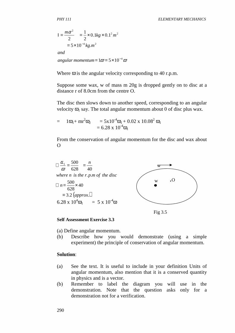
PHY 111 ELEMENTARY MECHANICS
290
Where ω is the angular velocity corresponding to 40 r.p.m. Suppose some wax, w of mass m 20g is dropped gently on to disc at a distance r of 8.0cm from the centre O. The disc then slows down to another speed, corresponding to an angular velocity ω1 say. The total angular momentum about 0 of disc plus wax. = 1ω1+ mr2ω2 = 5x10⁻⁴ω1 + 0.02 x 10.082 ω1 = 6.28 x 10⁻⁴ω1
From the conservation of angular momentum for the disc and wax about O
6.28 x 10⁴ω1 = 5 x 10⁻⁴ω Self Assessment Exercise 3.3 (a) Define angular momentum. (b) Describe how you would demonstrate (using a simple
experiment) the principle of conservation of angular momentum. Solution: (a) See the text. It is useful to include in your definition Units of
angular momentum, also mention that it is a conserved quantity in physics and is a vector.
(b) Remember to label the diagram you will use in the demonstration. Note that the question asks only for a demonstration not for a verification.
ωω
α
4
24
222
1051
.105
1.01.02
1
2
−
−
×==
×=
××==Ι
momentumangular
and
mkg
mkgm
( ).2.3
40628
500
..40628
5001
approx
n
disctheofmprtheisnwhere
n
=
×=∴
==∴ωω
w
w .O
Fig 3.5
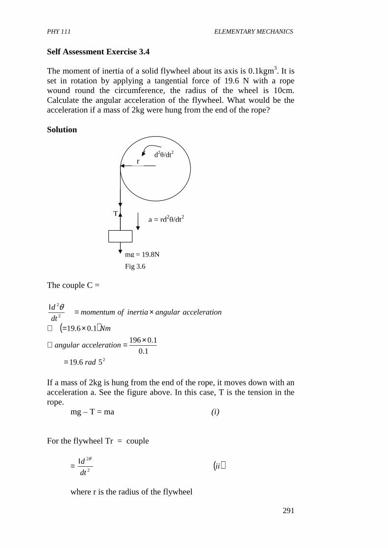
PHY 111 ELEMENTARY MECHANICS
291
Self Assessment Exercise 3.4 The moment of inertia of a solid flywheel about its axis is 0.1kgm3. It is set in rotation by applying a tangential force of 19.6 N with a rope wound round the circumference, the radius of the wheel is 10cm. Calculate the angular acceleration of the flywheel. What would be the acceleration if a mass of 2kg were hung from the end of the rope? Solution The couple C =
If a mass of 2kg is hung from the end of the rope, it moves down with an acceleration a. See the figure above. In this case, T is the tension in the rope.
mg – T = ma (i) For the flywheel Tr = couple
where r is the radius of the flywheel
( )
2
2
2
56.19
1.0
1.0196
1.06.19
rad
onacceleratiangular
Nm
onacceleratiangularinertiaofmomentumdt
d
=
×=∴
×=∴
×=Ι θ
( )iidt
d2
2θΙ=
T
mg = 19.8N
r d2θ/dt2
a = rd2θ/dt2
Fig 3.6
PHY 111 ELEMENTARY MECHANICS
292
Now, the mass of 2kg descends a distance given by rθ where θ is the angle the flywheel has turned. Hence the acceleration a = rd2 θ/ dt2. Substituting we have
3.1.5 The Top and the Gyroscope A symmetrical body rotating about an axis, one point of which is fixed is called a top. If the fixed point is at the centre of gravity, the body is called a gyroscope. We note that the axis of rotation of a top or gyroscope can itself rotate about the fixed point so the direction of the angular momentum vector can change. An example of the mounting of a toy gyroscope is shown in figure 3.7 below
Fig 3.7: Vector ∆L is the change in Angular Momentum produced in time ∆t by the moment Γ of the force w Vectors ∆L and Γ are in the same direction.
( )( ) ( )
( )
( )2
2
22
2
2
2
2
22
2
2
7.16
1.021.0
1.0102
−=×+××=
+Ι=∴
+Ι=
=−
=−
Srad
mr
mgr
dt
d
dt
dmrmrg
iiiandiieqnsadding
iiidt
dmrTrmgr
dt
dmrTmg
θ
θ
θ
θ
PHY 111 ELEMENTARY MECHANICS
293
The top (since the fixed point is not at the centre of mass) is spinning about its axis of symmetry and if the axis is initially set in motion in the direction shown, with the proper angular velocity, the system continues to rotate uniformly about the pivot at O. The spin axis remains horizontal. The angular momentum of a top would equal the product of its moment of inertia about the axis and its angular velocity about the axis would point along it. If It’s axis were fixed in space. But since the axis itself also rotates the angular momentum no longer lies on the axis. However, if the angular velocity of the axis itself is small compared to the angular velocity about the axis, then the component of the angular momentum arising from former effect is small and can be neglected. The angular momentum vector L, about the fixed point O, can then be drawn along the axis as shown and as the top rotates about O, its angular momentum vector rotates with it. The upward force P at the pivot has no moment about O. The resultant external moment is that due to the weight w; its magnitude is Γ = ωR 3.14 The direction of Γ is perpendicular to the axis as shown. In a time ∆t, this torque produces a change ∆L in the angular momentum, having the same direction as Γ and given by ∆L = Γ∆t 3.15 The angular momentum L + ∆L, after a time ∆L is perpendicular to L, the new angular momentum vector has the same magnitude as the old but a different direction. The top of the angular momentum vector moves as shown, and as time goes on it swings around a horizontal circle. Since the angular momentum vector lies along the gyroscope axis, the axis turns also, rotating in a horizontal plane about the point O. This motion of the axis of rotatiion is called precession”. (Sears et at, 1975) 4.0 CONCLUSION. In this unit, you have learnt that • applied torque increases the angular velocity of a rotating body. • torque , Γ =
where, I is the moment of inertia and ω is angular velocity.
dt
dI
ω
PHY 111 ELEMENTARY MECHANICS
294
• work done by a couple or torque is given by the kinetic energy of rotation. That is
• the angular momentum L of a rotating body is given by
L = Iω
• the total angular momentum of a system remains constant
provided no external torque acts on the system – rigid or otherwise.
• a symmetric body rotating about an axis, one point of which is fixed is called a top.
5.0 SUMMARY What you have learnt in this unit concerns the angular momentum of a rigid body. You have learnt that: • torque is the rotational analogue of force in linear motion. • to increase the angular velocity of a rotating body a torque or a
couple must be applied. • torque is given by Γ where • K.E of rotation is
• the angular momentum L of a system about an axis is defined as the moment of its momentum about that axis.
L =I ω • when the net torque on a system in rotational motion is zero, the
angular momentum is independent of time and is conserved. • using the formulas in this Unit and in the previous one you can
solve problems relating to angular momentum. • a gyroscope is a symmetrical body rotating about its centre of
gravity Summary of Equivalences Between Linear And Rotational Motion
212
1 ωθ =Γ
Ο=dt
dL
dt
Idω=Γ
2
2
1 ωθ Ι=Γ
PHY 111 ELEMENTARY MECHANICS
295
Quantity or Formular in Linear Motion
Equivalent in Rigid Body Rotation
Displacement (s) Velocity (V) Acceleration Mass ( m) Force ( f ) Kinetic energy Work done (Fs) F = ma m1v1+ m2 v2 = constant V = u + at etc
Angular displacement θ Angular velocity (ω)
Angular acceleration dt
dωα =⊥
Moment of inertia ( I ) Torque ( Γ ) Kinetic energy Work done ( Γθ) Γ = I α I1ω1+ I2ω2 = constant ωfinal = ωinitial + αt Etc
6.0 TUTOR MARKED ASSIGNMENT 1. A shaft rotating at 3 x 10³ revolutions per minute is transmitting
a power of 10 kilowatts. Find the magnitude of the driving couple.
2. The turntable of a record player is a uniform disc of moment of
inertia 1.2 x 10⁻² kg m2. When the motor is switched on it takes 2.5s for the turntable to accelerate uniformly from rest to 3.5 rad s-1 (33 1/3 r.p.m.) (a) What is the angular acceleration of the turntable? (b) What torque must the motor provide during this
acceleration?
3. A stationary horizontal hoop of mantle, 0.04 kg and mean radius 0.15m is dropped from a small height centrally and symmetrically onto a gramophone turntable which is freely rotating at an angular velocity of 3.0 rad. 51. Eventually the combined turntable and hoop rotate together with an angular velocity of 2.0 rad.S-1. Calculate
a = dv dt
1 mv2 2
1 Iω2
2
PHY 111 ELEMENTARY MECHANICS
296
(i) The moment of inertia of the turntable about its rotation axis
(ii) The original kinetic energy of the turntable. (iii) The eventual kinetic energy of the combined hoop and
turntable.
Account for any change in kinetic energy which has occurred. 7.0 REFERENCES AND FURTHER READING Sears F.W, Zemansky M.W and Young H.D (1975) College Physics (4th
Ed) Addison – Wesley Publ. Co. Reading. U.K. Fishbane P.M, Gasiorowicz, S and Thronton S.T, (1996). Physics For
Scientists and Engineers, (2nd Ed.) Prentice Hall Publ,New Jersey.
Nelkon M. and Parker P (1970) Advanced Level Physics Heinemann
Educational Books Ltd; London. Indira Ghandi National Open University School Of Sciences, PHE – 0l,
Elementary Mechanism Systems Of Particles.