Embed Size (px)
Citation preview

IF/P7-19
Elemental researches on the critical issue of laser fusion reactor KOYO-F
- Formation of aerosols, protection of beam port and flow stability -
T. Norimatsu1, T. Oshige1, Y. Shimada2, H. Furukawa2, T. Kunugi3, H. Nakajima4, Y. Kajimura5, and
K. Mima1,
1 Institute of Laser Engineering, Osaka University, 2-6, Yamada-oka, Suita, Osaka 56500871, Japan 2 Institute for Laser Technology, 1-8-9, Utubohonmachi, Nishiku, Osaka 550-0004, Japan 3 Kyoto University, Yoshida-Honmach, Sakyo-ku, Kyoto 606-8501, Japan 4 Kyusyu University, 6-1 Kasuga-koenn, Kasuga, 816-8580, Japan 5 Research Institute for Sustainable Humanosphere, Kyoto University, Uji, Kyoto 611-0011, Japan
E-mail contact of main author: [email protected]
Abstract. Critical issues on laser fusion reactor with a liquid wall are discussed. Formation of aerosols
after laser shot was studied experimentally and theoretically. Our simulation results for formation of
aerosols agreed with experimental results obtained with electric discharge through a thin lead membrane.
Formation of micro particles is discussed basing on experimental results obtained by backside irradiation
of a lead membrane. Protection of beam ports of the laser fusion reactor with a liquid first wall is
described. A magnetic field generated with a pulse current successfully shielded the tip of beam ports
from alpha particles. A continuous protective liquid LiPb flow controlled with cascade scheme was
formed as the protective first wall of KOYO-F.
1. Introduction
Many concepts for inertial fusion reactor were reported during 1975 through 1980. HYLIFE II
for heavy ion beam was continuously studied[1]. The ARIES-IFE team reported many modern,
useful papers, which can be seen on a web site[2]. ILE Osaka and the IFE Forum organized a laser
fusion reactor design committee to conceptually design the laser fusion power plant KOYO-F based
on fast ignition scheme and the result was reported at IAEA-FEC 2006[3]. KOYO-F has a liquid
LiPb flow as the first protective wall[4]. After the activity of the committee, we concentrated
elemental researches on the issues to increase the reliability of the concept under co-lateral
collaborations with other universities. Formation of aerosols and micro particles was studied at ILE
Osaka University and ILT Osaka. The researches include two types of experiments on formation of
aerosols and micro-particles produced by hydrodynamic instabilities during the ablation process. In
the case of KOYO-F, the alpha load on the first wall is about 0.35 MJ/m2 in 0.1 μsec. As the result,

IF/P7-19
10 kg of LiPb evaporates after fusion burn. Major part of ablated material condenses on the surface
of opposite wall. Some part of evaporated vapor stagnates at the center of the target chamber and,
in the worst case, the stagnated vapor makes lot of liquid droplets at the center, which would disables
a high repetition rate. Protection of beam ports is another important issue. Use of a thin liquid LiPb
membrane fed through a porous wall would be the solution[5] but some protective mechanism is
desired to increase the reliability. We propose use of a magnetic field to reduce the thermal load on
the tip of the beam port. The scheme was numerically studied at the Kyushu University and the
Kyoto University. Stability of liquid LiPb flow is experimentally and numerically investigated at
Kyoto University. When the surface flow is a simple laminar flow, the surface temperature becomes
to high to evacuate the chamber by cryogenic effect in designated time of 0.25 sec. The surface
flow must be mixed with the inner cold flow to keep the temperature low. A cascade flow was
proposed but the stability of flow as the protective first wall was not clear at the time.
2. Aerosols and Micro Particles
2.1 Discharge method
It is quite difficult to experimentally simulate the ablation process and formation of aerosols by
alpha particles in the wet wall reactor. Up to date, numerical simulation is a good tool to
understand the processes. We employed discharge method to check the simulation code.
A 5-mm-wide, 10-mm-long, 10-μm-thick, Pb ribbon target was heated to 3000 – 4000 K in 100 μs
by an electric discharge from a. 150 μF, 2kV capacitor. [6] The target was 10 μm thick Pb membrane
coated on a glass plate by physical vapor deposition. The glass plate was regarded as cold LiPb
beyond the Bragg’s peak. Evaporated materials were deposited on glass witness plates located 10 –
20 mm apart from the source. The spatial distribution of temperature was monitored by using a
charge-coupled device (CCD) camera equipped with band-pass filters that were inserted in front of
the pinholes to disperse the plasma emission at 460 nm and 660 nm in order to determine the color
temperature. Morphology of deposited materials was observed with a SEM and the average
thickness was measured from the intensity of fluorescent x-ray stimulated with a collimated Cu-K
x-ray beam from a tube.
Figure 1 shows the time-integrated, temperature distribution observed from the front (a) and the
side (b) of the Pb membrane. In the front view we can say the temperature distribution is quite
uniform and there is no narrow current path. In the side view, we found quite high temperature
zone existed 2 mm apart from the initial Pb membrane. We think that the second current path moved

IF/P7-19
to the low density region where the mobility of electrons was high. Because of damping oscillation
of discharge current, the electric power consumed at the Pb membrane had two peaks at 20 μs and
80 μs. We think influence of the change of the discharge path on the formation of aerosols was small
because the growth rate of aerosols in hot, low density plasma is slow.
(a) (b)
Fig. 1 Temperature distribution of discharge plasma. Front view (a), and side view (b)
Fig. 2 Surface and cross section of deposited materials on a glass plate. There is continuous
membrane under micro particles.
Lot of 30-nm-diameter particles were observed on a witness plate as shown in Fig. 2. Small
particles whose diameter ranged 30 to 40 nm were found on a 30 nm thick, continuous membrane.
This experimental result was compared with the simulation code DECORE (DEsign COde for
REactor) [7].

IF/P7-19
Fig. 3 Simulation on expansion of plasma from a 10 μm thick, 3000K, free standing Pb membrane.
The temperature and the density profile (a) and the diameter of aerosols (b) at 40 ns after the start of
expansion..
Figure 3 shows spatial profiles of the temperature, the density, the condensation rate and the
diameter of aerosols at 40 ns after the discharge. Initially 10 μm thick, 3000K Pb begins to expand to
both directions. Lot of 30 nm diameter aerosols are formed in the middle of expanding gas. The
vapor pressure of gases of leading portion ( |Z| > 50 μm) is much less than its vapor pressure at the
temperature. The gas is in super-cooled condition. In DECORE, estimation of formation of aerosol
at the region of super-cooled gas is omitted. The diameter of aerosols are calculated only -50 < z <
50 μm. Outside of this region, the diameter will rapidly decrease because of decreases in the density
and the temperature. When this leading portion collides with the witness plate, vapor condenses on
the witness plate as a continuous layer as shown in Fig. 2. Then, the trailing portion that contains lot
of aerosols deposits on the continuous layer. As we mentioned in a previous section, this leading
portion would be heated with the second pulse, which helped to form a continuous membrane on the
witness plate.
Average diameter of particles on the witness plate was very close to that numerically calculated
with DECORE. Two layer structure of the deposited Pb could be explained with above mentioned
model but we need additional experiment to say we successfully captured aerosols. .
2.1 Laser back lighting
Another interest is hydrodynamic instabilities due to the spatial distribution of deposited energy by
alpha particles. Alpha particles release their energy at the Bragg’s peak. Figure 4 shows thermal
load by particles on the first wall (a) and time integrated energy deposition in liquid Pb (b). Since

IF/P7-19
energy of alpha particles decreases with time due to collisions with compressed core plasma, the
position of Bragg peak approaches to the surface.. As the result, the liquid metal surface is ablated as
if an 3 – 10 μm thick membrane is lift off.
(a) (b)
Fig. 4 Thermal loads by particles on the first wall of KOYO-F(a) and the energy deposition in Pb (b)
To experimentally simulate this phenomenon, we fired a 10- μm-thick Sn layer on a transparent
glass plate from the glass plate side with a 0.08J/pulse, 15 ns, Nd:YAG laser. The laser energy
deposits between the Sn membrane and the glass plate, which accelerates the Sn membrane. The
glass plate was regarded as a residual LiPb flow. The absorbed laser energy density was estimated to
0.15 MJ/m2 in 15 ns while heat load of alpha particles is 0.35 MJ/m2 in 100ns . A plume from the
laser spot was back lighted with different timings
Fig. 5 Experimental setup to simulate ablation by particles that have Bragg peaks.

IF/P7-19
Fig. 6 Time elapsed images of plumes
Figure 6 shows back lighted images of plume at different timing. Since the spatial resolution of
the image was about 10 μm, dots in images did not correspond to actual size of particles but we
could see illustrated structure of the plume. Low density gas or aerosols lead heavy, large particles.
We attributed formation of these large droplets to the hydrodynamic instabilities in the membrane.
It is known that the growth late of hydrodynamic instabilities in an accelerated membrane takes its
maximum when the spatial wavelength of perturbation is close to the thickness of the membrane.
That means largest diameter of the droplet in this experiment is about 10 μm.
When we apply this experiment result to the KOYO-F case, we had to consider followings; 1) the
heating process in the KOYO-F case is volumetric heating, 2) the peak location is 2 - 3 μm deep
while laser experiment was surface heating at 10 μm deep, and 3) the temperature of ablated vapor is
still higher than its boiling point at 1932ns as shown in Fig 7. Our preliminary estimation says that
the largest diameter of micro particles formed by this instability will be about 1 - 2 μm that is 10
times larger than that of aerosols.
We also found that the plume was strongly oriented to the perpendicular to the surface. The
speed of the mass center was 1 – 1.5 km/s. This result seems encouraging to reduce the stagnation
of ablated materials by tilting the front panels. In the case of KOYO-F, temperature of ablated
vapor is 2000K and the leading portion is heated to 3500K due to slow component from plasma as
shown in Fig. 7. Expansion parallel to the surface with thermal velocity must be added to the
perpendicular velocity to discuss the stagnation of ablated materials at the chamber center.
IF/P7-19
500
1000
1500
2000
2500
3000
3500
4000
4500
-0.2 0 0.2 0.4 0.6 0.8 1 1.2
R = 3 m
595.5 ns
1932 ns
Tem
pera
ture
(K)
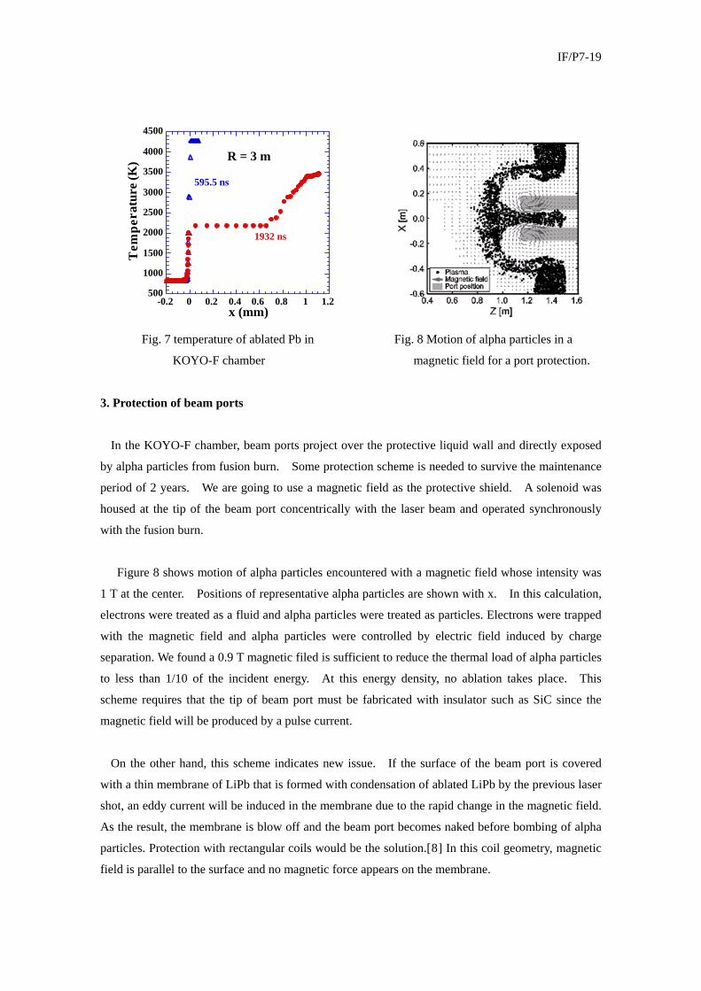
x (mm) Fig. 7 temperature of ablated Pb in Fig. 8 Motion of alpha particles in a
KOYO-F chamber magnetic field for a port protection.
3. Protection of beam ports
In the KOYO-F chamber, beam ports project over the protective liquid wall and directly exposed
by alpha particles from fusion burn. Some protection scheme is needed to survive the maintenance
period of 2 years. We are going to use a magnetic field as the protective shield. A solenoid was
housed at the tip of the beam port concentrically with the laser beam and operated synchronously
with the fusion burn.
Figure 8 shows motion of alpha particles encountered with a magnetic field whose intensity was
1 T at the center. Positions of representative alpha particles are shown with x. In this calculation,
electrons were treated as a fluid and alpha particles were treated as particles. Electrons were trapped
with the magnetic field and alpha particles were controlled by electric field induced by charge
separation. We found a 0.9 T magnetic filed is sufficient to reduce the thermal load of alpha particles
to less than 1/10 of the incident energy. At this energy density, no ablation takes place. This
scheme requires that the tip of beam port must be fabricated with insulator such as SiC since the
magnetic field will be produced by a pulse current.
On the other hand, this scheme indicates new issue. If the surface of the beam port is covered
with a thin membrane of LiPb that is formed with condensation of ablated LiPb by the previous laser
shot, an eddy current will be induced in the membrane due to the rapid change in the magnetic field.
As the result, the membrane is blow off and the beam port becomes naked before bombing of alpha
particles. Protection with rectangular coils would be the solution.[8] In this coil geometry, magnetic
field is parallel to the surface and no magnetic force appears on the membrane.

IF/P7-19
4. Stability of cascade flow.
We proposed a cascade flow of liquid LiPb (Fig 9) to protect the first structural wall of the reactor
from the alpha particles. To know the minimum flow rate at which a continuous layer of liquid
LiPb is formed on the first wall, we made a three-step mockup using acrylic resin and water. The
mockup was designed so that the Weber number of the flow was the same as the actual liquid LiPb
flow from the view point of flow stability.
(a) (b) Fig. 9 Cascade scheme of KOYO-F (a) and mock-up experiment with water (b).
A 5-mm-thick stable flow was formed on a 30-cm-high, 15-cm-wide, acrylic panel. The
minimum flow rate to obtain the continuous flow was confirmed experimentally and numerically [9]
Mixing of surface flow. With the inner flow was experimentally confirmed by injecting hot water
into the top cascade.
References 1 R. W. Moir et al., Fusion Technol., 25, 5 (1994). 2 http://aries.ucsd.edu/ARIES/DOCS/bib.shtml 3 T. Norimatsu et al., Presented at IAEA-FEC 2006, Chendo, China. (FT/P5-39) 4 T. Norimatsu, et al., Fusion Science and Technol., 52 893-900 (2007) 5 A. R. Raffray, et al., Fusion Science and Technol., 46, 438-450 (2004). 6 T. Ohshige, et. al.; IFSA2007 Proceeding, IOP Publishing, Journal of Physics: Conference Series 112 (2008), 032040., http://iopscience.iop.org/1742-6596/112/3/032040/ 7 H. Furukawa, IFSA2007 Proceeding, IOP Publishing, Journal of Physics: Conference Series 112 (2008) 032041, http://iopscience.iop.org/1742-6596/112/3/032041/ 8 Y. Kajimura, et al., Presented at ICPP 2008, Fukuoka, Japan, CFR P3-138. 9 T. Kunugi, et al., to be published in Fusion Eng. Design. (2008).
![Infrared and visible image fusion based on nonlinear ......image fusion [31]. Many researches have shown that NSST is more consistent with hu-man visual characteristics than other](https://img.pdfslide.us/doc/110x75/60a7636e7fb6cc0e8a5306f8/infrared-and-visible-image-fusion-based-on-nonlinear-image-fusion-31.jpg)