Embed Size (px)
Citation preview
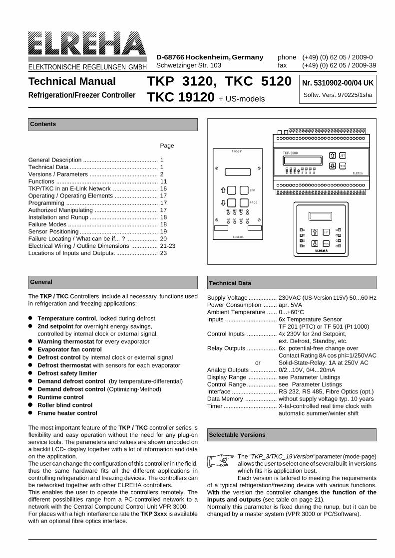
Technical ManualRefrigeration/Freezer Controller
Contents
Page
General Description ............................................. 1Technical Data ..................................................... 1Versions / Parameters ......................................... 2Functions ............................................................. 11TKP/TKC in an E-Link Network ........................... 16Operating / Operating Elements .......................... 17Programming ....................................................... 17Authorized Manipulating ...................................... 17Installation and Runup ......................................... 18Failure Modes ...................................................... 18Sensor Positioning ............................................... 19Failure Locating / What can be if... ? ................... 20Electrical Wiring / Outline Dimensions ................ 21-23Locations of Inputs and Outputs. ......................... 23
General
The TKP / TKC Controllers include all necessary functions usedin refrigeration and freezing applications:
l Temperature control , locked during defrostl 2nd setpoint for overnight energy savings,
controlled by internal clock or external signal.l Warning thermostat for every evaporatorl Evaporator fan controll Defrost control by internal clock or external signall Defrost thermostat with sensors for each evaporatorl Defrost safety limiterl Demand defrost control (by temperature-differential)l Demand defrost control (Optimizing-Method)l Runtime controllllll Roller blind controll Frame heater control
The most important feature of the TKP / TKC controller series isflexibility and easy operation without the need for any plug-onservice tools. The parameters and values are shown uncoded ona backlit LCD- display together with a lot of information and dataon the application.The user can change the configuration of this controller in the field,thus the same hardware fits all the different applications incontrolling refrigeration and freezing devices. The controllers canbe networked together with other ELREHA controllers.This enables the user to operate the controllers remotely. Thedifferent possibilities range from a PC-controlled network to anetwork with the Central Compound Control Unit VPR 3000.For places with a high interference rate the TKP 3xxx is availablewith an optional fibre optics interface.
Technical Data
Supply Voltage ................. 230VAC (US-Version 115V) 50...60 HzPower Consumption ........ apr. 5VAAmbient Temperature ...... 0...+60°CInputs ............................... 6x Temperature Sensor
TF 201 (PTC) or TF 501 (Pt 1000)Control Inputs .................. 4x 230V for 2nd Setpoint,
ext. Defrost, Standby, etc.Relay Outputs .................. 6x potential-free change over
Contact Rating 8A cos phi=1/250VACor Solid-State-Relay: 1A at 250V AC
Analog Outputs ................ 0/2...10V, 0/4...20mADisplay Range ................. see Parameter ListingsControl Range .................. see Parameter ListingsInterface ........................... RS 232, RS 485, Fibre Optics (opt.)Data Memory ................... without supply voltage typ. 10 yearsTimer ................................ X-tal-controlled real time clock with
automatic summer/winter shift
Nr. 5310902-00/04 UKSoftw. Vers. 970225/1sha
ELEKTRONISCHE REGELUNGEN GMBH
TKP 3120, TKC 5120TKC 19120 + US-models
D-68766 Hockenheim, GermanySchwetzinger Str. 103
phone (+49) (0) 62 05 / 2009-0fax (+49) (0) 62 05 / 2009-39
Selectable Versions
The "TKP_3/TKC_19 Version" parameter (mode-page)allows the user to select one of several built-in versionswhich fits his application best.Each version is tailored to meeting the requirements
of a typical refrigeration/freezing device with various functions.With the version the controller changes the function of theinputs and outputs (see table on page 21).Normally this parameter is fixed during the runup, but it can bechanged by a master system (VPR 3000 or PC/Software).
1 32 1 2 3 4
TKP-3000
ELREHA
P R O G
LIST
ELREHA
1
1
2 3 4
2 3
P R O G
LIST
TKC-19"
4
2
3
1LIST
ELREHA
P R O G
6
7
8
5

Technical Manual TKP / TKC valid for Software Vers. 970225/1sha Page 2
Version: AApplication: Two (2) separate control circuits with one (1) evaporator each. This controller version is used in applications
where two individual cooling circuits are to be controlled and each single circuit has not more than one evaporator.Since there is no extra relay output for the fan, the fans run constantly or are hooked up to the cooling output.
Warning: The temperature warning thermostat uses a common offset from the individual setpoints. The warning output iscommon for both circuits.
Defrosting: Defrosting is initiated from either the built-in timer or from a remote signal. Defrosting on demand (optimizingmethod) can be selected. Sensors in the evaporators are used for individual defrost termination whilst the selected(safety) termination time is common for both circuits. Cooling comes on again upon defrost termination of both circuits.
2nd Setpoint: The internal timer or a control input can be used for toggling between two (2) setpoints. The 2nd setpoint is oftenused for overnight operation with increasedtemperature for energy savings.
Special Function: One sensor is called the 'shop sensor' andcan be used to capture any temperatures. Ver-sion A contains roller blind / frame heatercontrol. A separate control input allows ofswitching the controller in ‘standby’. This cancelsout the control functions but keeps the controllerunder power.
Parameter: The following parameters are available if"TKP_3 /TKC_19" (Modes) is set to "Version A"
Wiring: see page 21, please note table!
Modes Version ADisp
onlyRange Dimension Default
TKP_3 / TKC_19 Version A, C, E, F, I, K, L, M, N
Status X ON, OFF
Compound R/F X Frz Comp. / Refr Comp
Solenoid Valve X enabled / disabled enabled
Night Settings X ON, OFF
Defrost Type Electric, Free Air
Cooling Mode Refrigeration / Freezing Refrigerat.
Defrost (Init) Mode
extern (only), extern + internal,
Dem Def by Differential,
Dem Def by Optimizing
extern +
internal
Additional Function Roller Blind / Frame Heater Roller Blind
Frequency 00:00:10 to 01:00:00 h:min:sec
Pulse Width 0 to 100% %
Control Parameter Room Sensor / Defrost Sensor Room sens.
Operation Mode Stand alone, Master Stand alone
n/o Defr Ignored 0, 1, 2, 3, 4, 5, 6 0
Defrost Time 1 00:00:00 h:min:sec 5:00:00
Defrost Time 2 00:00:00 h:min:sec 5:00:00
Defrost Time 3 00:00:00 h:min:sec 5:00:00
Defrost Time 4 00:00:00 h:min:sec 5:00:00
Defrost Time 5 00:00:00 h:min:sec 5:00:00
Defrost Time 6 00:00:00 h:min:sec 5:00:00
Actual Time h:min:sec
Date day:month:year
Program Version X
2nd Setting ON 00:00:00 to 24:00:00 24:00:00
2nd Setting OFF 00:00:00 to 24:00:00 24:00:00
Actual Failure X
Historical Failure 1 X day.month.time Failure Code
Historical Failure 2 X day.month.time Failure Code
Historical Failure 3 X day.month.time Failure Code
Historical Failure 4 X day.month.time Failure Code
Historical Failure 5 X day.month.time Failure Code
Correction Sensor 1 Corr Factor (Disp only) / Off K 0 K
Correction Sensor 2 Corr Factor (Disp only) / Off K 0 K
Correction Sensor 3 Corr Factor (Disp only) / Off K 0 K
Correction Sensor 4 Corr Factor (Disp only) / Off K 0 K
Correction Sensor 5 Corr Factor (Disp only) / Off K 0 K
Correction Sensor 6 Corr Factor (Disp only) / Off K 0 K
Check data X
Analog Output Para PI-Control / Act Sens Value Ac Sens Val
Analog Output 0-100%, 20-100% 0-100%
Summer/Winter sw
0= Off
1= EU up to 1995
2= EU coming in 1996
1
TKP 1901_Emulat. ON / OFF OFF
Sensor TF 201, Pt 1000 TF 201
Adress in Network 1 - 79 0
Default values and settings are factory settings. Valuesmarked 'Display only' are for information only and can not beedited. Warning : Do not change parameter "TKP1901_Emulat" at TKP 3xxx and TKC 5xxxx !
Settings Version A Range Default
Setpoint Channel 1 +/- 50,0°C -20°C
Setpoint Channel 2 +/- 50,0°C -20°C
2nd Setpoint Ch 1 +/- 50,0°C -20°C
2nd Setpoint Ch 2 +/- 50,0°C -20°C
Hysteresis 0,1...20 K 2 K
Ch 1 Propor Band 0,1...20 K 10 K
Ch 1 Integral Time 00:00...60:00 min:sec 20 sec.
Warning Offset 0...35 K 7 K
Warning low Limit +/- 50,0°C -22°C
Warning Delay 0:00:00 to 2:00:00 ( h:min:sec ) 0:15:00
max Defrost Time 0:00:00 to 4:00:00 ( h:min:sec ) 0:45:00
Defrost Alarm Delay 0:00:00 to 1:00:00 ( h:min:sec ) 0:30:00
Defrost Temp Ch 1 0...50°C 14°C
Defrost Temp Ch 2 0...50°C 14°C
Cooling Limit 0:00:00 to 24:00:00 ( h:min:sec ) 24:00:00
Manual Defrost 1 = Manual Defrost Initiation 0
Cooling delay
(after Defrost)0:00:00 to 0:30:00 ( h:min:sec ) 0:00:00
Actual ValuesVersion A
Displ.only
Range Default
Room Sensor 1Display -50/+100°CCorrection +/- 10K
+/- 0K
Defrost Sensor 1Display -50/+100°CCorrection +/- 10K
+/- 0K
Room Sensor 2Display -50/+100°CCorrection +/- 10K
+/- 0K
Defrost Sensor 2Display -50/+100°CCorrection +/- 10K
+/- 0K
Shop TemperatureDisplay -50/+100°CCorrection +/- 10K
+/- 0K
Remaining Defr Time X h:min:sec. 0:00:00
Remain Warn Delay X h:min:sec. 0:00:00
Run Time Cool 1 X 23h:59min:59sec. max. 0:00:00
Run Time Cool 2 X 23h:59min:59sec. max. 0:00:00
Remain Cool del(ay) X h:min:sec.
Technical Manual TKP / TKC valid for Software Vers. 970225/1sha Page 3
Version: CApplication: One (1) control circuit with three (3) evaporators. This version is used in single control circuits where up to three
(3) evaporators are to be controlled. Since there is no extra relay output for the fan, the fans run constantly or are hookedup to the cooling output. One room sensor is used as the control sensor and the other room sensors are used formonitoring and temperature warning.
Warning: Temperature warning is activated if the value of one room sensor increases a set offset from the setpoint. All temperaturewarning works on one output relay.
Defrosting: Defrosting is initiated from either the built-in timer or from a remote signal. Defrosting on demand (optimizing method)can be selected. Each evaporator has its own defrost termination sensor whilst the selected (safety) termination timeis common for all evaporators. Cooling is cancelled until all evaporators have finished their individual defrost cycle.
2nd Setpoint: The internal timer or a control input can be used for toggling between two (2) setpoints. The 2nd setpoint is often usedfor overnight operation with increasedtemperature for energy savings.
Special Function: The user can select one relay output forcontrolling the roller blind or the frame heater .A separate control input allows of switching thecontroller in ‘standby’. This cancels out thecontrol functions but keeps the controller underpower.
Parameter: The following parameters are available if"TKP_3/TKC_19" (Modes) is set to "Version C"
Wiring: see page 21, please note table!
Actual Values
Version C
Displ.
onlyRange Default
Room Sensor 1Display -50/+100°C
Correction +/- 10K+/- 0K
Defrost Sensor 1Display -50/+100°C
Correction +/- 10K+/- 0K
Room Sensor 2Display -50/+100°C
Correction +/- 10K+/- 0K
Defrost Sensor 2Display -50/+100°C
Correction +/- 10K+/- 0K
Room Sensor 3Display -50/+100°C
Correction +/- 10K+/- 0K
Defrost Sensor 3Display -50/+100°C
Correction +/- 10K+/- 0K
Remaining Defr Time X h:min:sec. 0:00:00
Remain Warn Delay X h:min:sec. 0:00:00
Run Time Cool 1 X 23h:59min:59sec. max. 0:00:00
Remain Cool del(ay) X h:min:sec.
Settings Version C Range Default
Setpoint Channel 1 +/- 50,0°C -20°C
2nd Setpoint Ch 1 +/- 50,0°C -20°C
Hysteresis 0,1...20 K 2 K
Ch 1 Propor Band 0,1...20 K 10 K
Ch 1 Integral Time 00:00...60:00 min:sec 20 sec.
Warning Offset 0...35 K 7 K
Warning low Limit +/- 50,0°C -22°C
Warning Delay 0:00:00 to 2:00:00 ( h:min:sec ) 0:15:00
max Defrost Time 0:00:00 to 4:00:00 ( h:min:sec ) 0:45:00
Defrost Alarm Delay 0:00:00 to 1:00:00 ( h:min:sec ) 0:30:00
Defrost Temp Ch 1 0...50°C 14°C
Defrost Temp Ch 2 0...50°C 14°C
Defrost Temp Ch 3 0...50°C 14°C
Cooling Limit 0:00:00 to 24:00:00 ( h:min:sec ) 24:00:00
Manual Defrost 1 = Manual Defrost Initiation 0
Cooling delay
(after Defrost)0:00:00 to 0:30:00 ( h:min:sec ) 0:00:00
Modes Version CDisp
onlyRange Dimension Default
TKP_3 / TKC_19 Version A, C, E, F, I, K, L, M, N
Status X ON, OFF
Compound R/F X Frz Comp. / Refr Comp
Solenoid Valve X enabled / disabled enabled
Night Settings X ON, OFF
Defrost Type Electric, Free Air
Cooling Mode Refrigeration / Freezing Refrigerat.
Defrost (Init) Mode
extern (only), extern + internal,
Dem Def by Differential,
Dem Def by Optimizing
extern +
internal
Additional Function Roller Blind / Frame Heater Roller Blind
Frequency 00:00:10 to 01:00:00 h:min:sec
Pulse Width 0 to 100% %
Control Parameter Room Sensor / Defrost Sensor Room sens.
Operation Mode Stand alone, Master Stand alone
n/o Defr Ignored 0, 1, 2, 3, 4, 5, 6 0
Last Defrost Cycle X h:min
Defrost Time 1 00:00:00 h:min:sec 5:00:00
Defrost Time 2 00:00:00 h:min:sec 5:00:00
Defrost Time 3 00:00:00 h:min:sec 5:00:00
Defrost Time 4 00:00:00 h:min:sec 5:00:00
Defrost Time 5 00:00:00 h:min:sec 5:00:00
Defrost Time 6 00:00:00 h:min:sec 5:00:00
Actual Time h:min:sec
Date day:month:year
Program Version X
2nd Setting ON 00:00:00 to 24:00:00 24:00:00
2nd Setting OFF 00:00:00 to 24:00:00 24:00:00
Actual Failure X
Historical Failure 1 X day.month.time Failure Code
Historical Failure 2 X day.month.time Failure Code
Historical Failure 3 X day.month.time Failure Code
Historical Failure 4 X day.month.time Failure Code
Historical Failure 5 X day.month.time Failure Code
Correction Sensor 1 Corr Factor (Disp only) / Off K 0 K
Correction Sensor 2 Corr Factor (Disp only) / Off K 0 K
Correction Sensor 3 Corr Factor (Disp only) / Off K 0 K
Correction Sensor 4 Corr Factor (Disp only) / Off K 0 K
Correction Sensor 5 Corr Factor (Disp only) / Off K 0 K
Correction Sensor 6 Corr Factor (Disp only) / Off K 0 K
Check data X
Analog Output Para PI-Control / Act Sens Value Ac Sens Val
Analog Output 0-100%, 20-100% 0-100%
Summer/Winter sw
0= Off
1= EU up to 1995
2= EU coming in 1996
1
Adress in Network 1 - 79 0
Default values and settings are factory settings.Values marked 'Display only' are for information only andcan not be edited. Warning : Do not change parameter"TKP 1901_Emulat" at TKP 3xxx and TKC 5xxxx !
Technical Manual TKP / TKC valid for Software Vers. 970225/1sha Page 4
Version: EApplication: One (1) control circuit with three (3) evaporators and controlled evaporator fan(s). This version is used in single
control circuits where up to three (3) evaporators are to be controlled. One output is available for fan control. ‘Intervall’or ‘Permanent’ mode can be selected and a start up time delay after defrost eliminates water being splashed around.One room sensor is used as the control sensor and the other room sensors are used for monitoring and temperaturewarning.
Warning: Temperature warning is activated if the value of one room sensor increases a set offset from the setpoint. All temperaturewarning works on one output relay.
Defrosting: Defrosting is initiated from either the built-in timer or from a remote signal. Defrosting on demand (optimizing method)can be selected. Each evaporator has its own defrost termination sensor whilst the selected (safety) termination timeis common for all evaporators. Cooling is cancelled until all evaporators have finished their individual defrost cycle.
2nd Setpoint: The internal timer or a control input can be used for toggling between two (2) setpoints. The 2nd setpoint is often usedfor overnight operation with increased temperature for energy savings.
Special Function: A separate control input allows of switchingthe controller in ‘standby’. This cancels out thecontrol functions but keeps the controller underpower.
Parameter: The following parameters are available if"TKP_3/TKC_19" (Modes) is set to "Version E"
Wiring: see page 21, please note table!
Actual Values
Version E
Displ.
onlyRange Default
Room Sensor 1Display -50/+100°C
Correction +/- 10K+/- 0K
Defrost Sensor 1Display -50/+100°C
Correction +/- 10K+/- 0K
Room Sensor 2Display -50/+100°C
Correction +/- 10K+/- 0K
Defrost Sensor 2Display -50/+100°C
Correction +/- 10K+/- 0K
Room Sensor 3Display -50/+100°C
Correction +/- 10K+/- 0K
Defrost Sensor 3Display -50/+100°C
Correction +/- 10K+/- 0K
Remaining Fan
DelayX h:min:sec. 0:00:00
Remaining Defr Time X h:min:sec. 0:00:00
Remain Warn Delay X h:min:sec. 0:00:00
Run Time Cool 1 X 23h:59min:59sec. max. 0:00:00
Remain Cool del(ay) X h:min:sec.
Modes Version EDisp
onlyRange Dimension Default
TKP_3 / TKC_19 Version A, C, E, F, I, K, L, M, N
Status X ON, OFF
Compound R/F X Frz Comp. / Refr Comp
Solenoid Valve X enabled / disabled enabled
Night Settings X ON, OFF
Defrost Type Electric, Free Air
Fan Operation Intervall / Permanent
Cooling Mode Refrigeration / Freezing Refrigerat.
Defrost (Init) Mode
extern (only), extern + internal,
Dem Def by Differential,
Dem Def by Optimizing
extern +
internal
Control Parameter Room Sensor / Defrost Sensor Room sens.
Operation Mode Stand alone, Master Stand alone
n/o Defr Ignored 0, 1, 2, 3, 4, 5, 6 0
Last Defrost Cycle X h:min
Defrost Time 1 00:00:00 h:min:sec 5:00:00
Defrost Time 2 00:00:00 h:min:sec 5:00:00
Defrost Time 3 00:00:00 h:min:sec 5:00:00
Defrost Time 4 00:00:00 h:min:sec 5:00:00
Defrost Time 5 00:00:00 h:min:sec 5:00:00
Defrost Time 6 00:00:00 h:min:sec 5:00:00
Actual Time h:min:sec
Date day:month:year
Program Version X
2nd Setting ON 00:00:00 to 24:00:00 24:00:00
2nd Setting OFF 00:00:00 to 24:00:00 24:00:00
Actual Failure X
Historical Failure 1 X day.month.time Failure Code
Historical Failure 2 X day.month.time Failure Code
Historical Failure 3 X day.month.time Failure Code
Historical Failure 4 X day.month.time Failure Code
Historical Failure 5 X day.month.time Failure Code
Correction Sensor 1 Corr Factor (Disp only) / Off K 0 K
Correction Sensor 2 Corr Factor (Disp only) / Off K 0 K
Correction Sensor 3 Corr Factor (Disp only) / Off K 0 K
Correction Sensor 4 Corr Factor (Disp only) / Off K 0 K
Correction Sensor 5 Corr Factor (Disp only) / Off K 0 K
Correction Sensor 6 Corr Factor (Disp only) / Off K 0 K
Check data X
Analog Output Para PI-Control / Act Sens Value Ac Sens Val
Analog Output 0-100%, 20-100% 0-100%
Summer/Winter sw
0= Off
1= EU up to 1995
2= EU coming in 1996
1
Adress in Network 1 - 79 0
Default values and settings are factory settings.Values marked 'Display only' are for information only andcan not be edited. Warning : Do not change parameter"TKP 1901_Emulat" at TKP 3xxx and TKC 5xxxx !
Settings Version E Range Default
Setpoint Channel 1 +/- 50,0°C -20°C
2nd Setpoint Ch 1 +/- 50,0°C -20°C
Hysteresis 0,1...20 K 2 K
Ch 1 Propor Band 0,1...20 K 10 K
Ch 1 Integral Time 00:00...60:00 min:sec 20 sec.
Warning Offset 0...35 K 7 K
Warning low Limit +/- 50,0°C -22°C
Fan Delay 0:00:00 to 0:30:00 ( h:min:sec ) 0:05:00
Warning Delay 0:00:00 to 2:00:00 ( h:min:sec ) 0:15:00
max Defrost Time 0:00:00 to 4:00:00 ( h:min:sec ) 0:45:00
Defrost Alarm Delay 0:00:00 to 1:00:00 ( h:min:sec ) 0:30:00
Defrost Temp Ch 1 0...50°C 14°C
Defrost Temp Ch 2 0...50°C 14°C
Defrost Temp Ch 3 0...50°C 14°C
Cooling Limit 0:00:00 to 24:00:00 ( h:min:sec ) 24:00:00
Manual Defrost 1 = Manual Defrost Initiation 0
Cooling delay
(after Defrost)0:00:00 to 0:30:00 ( h:min:sec ) 0:00:00

Technical Manual TKP / TKC valid for Software Vers. 970225/1sha Page 5
Version: FApplication: So this version is used in single control circuits with up to two (2) evaporators where the fans are to be
controlled and defrosting is initiated on demand according to the actual amount of icing . The main featureof this controller version is the demand defrost by the differential method. One room sensor is used as the controlsensor and the other room sensors are used for monitoring and temperature warning.
Warning: Temperature warning is activated if the value of one room sensor increases a set offset from the setpoint. All temperaturewarning works on one output relay.
Defrosting: Defrosting is requested by temperature difference and unblocked by either the built-in timer or a remote signal. Eachevaporator has its own defrost termination sensor whilst the selected (safety) termination time is common for bothevaporators. Cooling is cancelled until all evaporators have finished their individual defrost cycle.
2nd Setpoint: The internal timer or a control input can be usedfor toggling between two (2) setpoints.
Special Function: The user can select one relay output forcontrolling the roller blind or the frame heater .A separate control input allows of switchingthe controller in ‘standby’. This cancels out thecontrol functions but keeps the controller underpower.
Parameter: The following parameters are available if"TKP_3/TKC_19" (Modes) is set to "Version F"
Wiring: see page 21, please note table!
Settings Version F Range Default
Setpoint Channel 1 +/- 50,0°C -20°C
2nd Setpoint Ch 1 +/- 50,0°C -20°C
Hysteresis 0,1...20 K 2 K
Ch 1 Propor Band 0,1...20 K 10 K
Ch 1 Integral Time 00:00...60:00 min:sec 20 sec.
Warning Offset 0...35 K 7 K
Warning low Limit +/- 50,0°C -22°C
Fan Delay 0:00:00 to 0:30:00 ( h:min:sec ) 0:05:00
Warning Delay 0:00:00 to 2:00:00 ( h:min:sec ) 0:15:00
max Defrost Time 0:00:00 to 4:00:00 ( h:min:sec ) 0:45:00
Defrost Alarm Delay 0:00:00 to 1:00:00 ( h:min:sec ) 0:30:00
Defrost Temp Ch 1 0...50°C 14°C
Defrost Temp Ch 2 0...50°C 14°C
Cooling Limit 0:00:00 to 24:00:00 ( h:min:sec ) 24:00:00
Demand Defr Diff 0...20 K 5K
Dem Defr Period 0:01:00 to 1:00:00 ( h:min:sec ) 0:10:00
Dem Defr stored 1 = Defrost Demand stored Disp. only
Dem Defr Cycle On or Off Disp. only
Manual Defrost 1 = Manual Defrost Initiation 0
Cooling delay
(after Defrost)0:00:00 to 0:30:00 ( h:min:sec ) 0:00:00
Actual Values
Version F
Displ.
onlyRange Default
Room Sensor 1Display -50/+100°C
Correction +/- 10K+/- 0K
Defrost Sensor 1Display -50/+100°C
Correction +/- 10K+/- 0K
Room Sensor 2Display -50/+100°C
Correction +/- 10K+/- 0K
Defrost Sensor 2Display -50/+100°C
Correction +/- 10K+/- 0K
Dem Defr Sens coldDisplay -50/+100°C
Correction +/- 10K+/- 0K
Dem Defr Sens warmDisplay -50/+100°C
Correction +/- 10K+/- 0K
Remain Fan Delay X h:min:sec. 0:00:00
Remain Check Time X h:min:sec. 0:00:00
Remain Defr Time X h:min:sec. 0:00:00
Remain Warn Delay X h:min:sec. 0:00:00
Run Time Cool 1 X 23h:59min:59sec. max. 0:00:00
Remain Cool del(ay) X h:min:sec.
Modes Version FDisp
onlyRange Dimension Default
TKP_3 / TKC_19 Version A, C, E, F, I, K, L, M, N
Status X ON, OFF
Compound R/F X Frz Comp. / Refr Comp
Solenoid Valve X enabled / disabled enabled
Night Settings X ON, OFF
Defrost Type Electric, Free Air
Fan Operation Intervall / Permanent
Cooling Mode Refrigeration / Freezing Refrigerat.
Defrost (Init) Mode
extern (only), extern + internal,
Dem Def by Differential,
Dem Def by Optimizing
extern +
internal
Additional Function Roller Blind / Frame Heater Roller Blind
Frequency 00:00:10 to 01:00:00 h:min:sec
Pulse Width 0 to 100% %
Control Parameter Room Sensor / Defrost Sensor Room sens.
Operation Mode Stand alone, Master Stand alone
n/o Defr Ignored 0, 1, 2, 3, 4, 5, 6 0
Last Defrost Cycle X h:min
Defrost Time 1 00:00:00 h:min:sec 5:00:00
Defrost Time 2 00:00:00 h:min:sec 5:00:00
Defrost Time 3 00:00:00 h:min:sec 5:00:00
Defrost Time 4 00:00:00 h:min:sec 5:00:00
Defrost Time 5 00:00:00 h:min:sec 5:00:00
Defrost Time 6 00:00:00 h:min:sec 5:00:00
Actual Time h:min:sec
Date day:month:year
Program Version X
2nd Setting ON 00:00:00 to 24:00:00 24:00:00
2nd Setting OFF 00:00:00 to 24:00:00 24:00:00
Actual Failure X
Historical Failure 1 X day.month.time Failure Code
Historical Failure 2 X day.month.time Failure Code
Historical Failure 3 X day.month.time Failure Code
Historical Failure 4 X day.month.time Failure Code
Historical Failure 5 X day.month.time Failure Code
Correction Sensor 1 Corr Factor (Disp only) / Off K 0 K
Correction Sensor 2 Corr Factor (Disp only) / Off K 0 K
Correction Sensor 3 Corr Factor (Disp only) / Off K 0 K
Correction Sensor 4 Corr Factor (Disp only) / Off K 0 K
Correction Sensor 5 Corr Factor (Disp only) / Off K 0 K
Correction Sensor 6 Corr Factor (Disp only) / Off K 0 K
Check data X
Analog Output Para PI-Control / Act Sens Value Ac Sens Val
Analog Output 0-100%, 20-100% 0-100%
Summer/Winter sw
0= Off
1= EU up to 1995
2= EU coming in 1996
1
Adress in Network 1 - 79 0
Default values and settings are factory settings.Values marked 'Display only' are for information only andcan not be edited. Warning : Do not change parameter"TKP 1901_Emulat" at TKP 3xxx and TKC 5xxxx !

Technical Manual TKP / TKC valid for Software Vers. 970225/1sha Page 6
Version: IApplication: Chest freezers, refrigerated shelfs or similar consisting of one (1) pilot element and three (3) slave elements wit h
one (1) evaporator each.The control sensors are placed at the 'air out' opening, one additional alarm sensor is placed at the 'air in' opening. Sincethere is no extra relay output for the fan, the fans run constantly or are hooked up to the cooling output.
Warning: Temperature warning is activated if the value of one of the sensors increases a set offset from the setpoint 1.All temperature warning works on one output relay.
Defrosting: Air circulation defrosting . Defrosting is initiated from either the built-in timer or from a remote signal and disables thesolenoid valves. Defrosting on demand (optimizing method) can be selected. Each evaporator has its own defrosttermination sensor whilst the selected (safety) termination time is common for all evaporators. Cooling is cancelleduntil all evaporators have finished their individual defrost cycle.
2nd Setpoint: The internal timer or a control input can be usedfor toggling between two (2) setpoints. The 2ndsetpoint is often used for overnight operationwith increased temperature for energy savings.
Special Function: A 'shop sensor' can be used to capture anytemperatures. The user can select one relayoutput for controlling the roller blind or theframe heater . A separate control input allowsof switching the controller in ‘standby’.
Parameter: The following parameters are available if"TKP_3/TKC_19" (Modes) is set to "Version I"
Wiring: see page 21, please note table!
Modes Version IDisp
onlyRange Dimension Default
TKP_3 / TKC_19 Version A, C, E, F, I, K, L, M, N
Status X ON, OFF
Compound R/F X Frz Comp. / Refr Comp
Solenoid Valve X enabled / disabled enabled
Night Settings X ON, OFF
Defrost Type Electric, Free Air
Cooling Mode Refrigeration / Freezing Refrigerat.
Defrost (Init) Mode
extern (only), extern + internal,
Dem Def by Differential,
Dem Def by Optimizing
extern +
internal
Additional Function Roller Blind / Frame Heater Roller Blind
Frequency 00:00:10 to 01:00:00 h:min:sec
Pulse Width 0 to 100% %
Control Parameter Room Sensor / Defrost Sensor Room sens.
Operation Mode Stand alone, Master Stand alone
n/o Defr Ignored 0, 1, 2, 3, 4, 5, 6 0
Last Defrost Cycle X h:min
Defrost Time 1 00:00:00 h:min:sec 5:00:00
Defrost Time 2 00:00:00 h:min:sec 5:00:00
Defrost Time 3 00:00:00 h:min:sec 5:00:00
Defrost Time 4 00:00:00 h:min:sec 5:00:00
Defrost Time 5 00:00:00 h:min:sec 5:00:00
Defrost Time 6 00:00:00 h:min:sec 5:00:00
Actual Time h:min:sec
Date day:month:year
Program Version X
2nd Setting ON 00:00:00 to 24:00:00 24:00:00
2nd Setting OFF 00:00:00 to 24:00:00 24:00:00
Actual Failure X
Historical Failure 1 X day.month.time Failure Code
Historical Failure 2 X day.month.time Failure Code
Historical Failure 3 X day.month.time Failure Code
Historical Failure 4 X day.month.time Failure Code
Historical Failure 5 X day.month.time Failure Code
Correction Sensor 1 Corr Factor (Disp only) / Off K 0 K
Correction Sensor 2 Corr Factor (Disp only) / Off K 0 K
Correction Sensor 3 Corr Factor (Disp only) / Off K 0 K
Correction Sensor 4 Corr Factor (Disp only) / Off K 0 K
Correction Sensor 5 Corr Factor (Disp only) / Off K 0 K
Correction Sensor 6 Corr Factor (Disp only) / Off K 0 K
Check data X
Analog Output Para PI-Control / Act Sens Value Ac Sens Val
Analog Output 0-100%, 20-100% 0-100%
Summer/Winter sw
0= Off
1= EU up to 1995
2= EU coming in 1996
1
Adress in Network 1 - 79 0
Actual Values
Version I
Displ.
onlyRange Default
Air Out Sensor 1 Display -50/+100°C, Corr. +/- 10K +/- 0K
Air Out Sensor 2 Display -50/+100°C, Corr. +/- 10K +/- 0K
Air Out Sensor 3 Display -50/+100°C, Corr. +/- 10K +/- 0K
Air Out Sensor 4 Display -50/+100°C, Corr. +/- 10K +/- 0K
Shop Temperature Display -50/+100°C, Corr. +/- 10K +/- 0K
Air In Sensor 1 Display -50/+100°C, Corr. +/- 10K +/- 0K
Remaining Defr Time X h:min:sec. 0:00:00
Remain Warn Delay X h:min:sec. 0:00:00
Run Time Cool 1 X 23h:59min:59sec. max. 0:00:00
Run Time Cool 2 X 23h:59min:59sec. max. 0:00:00
Run Time Cool 3 X 23h:59min:59sec. max. 0:00:00
Run Time Cool 4 X 23h:59min:59sec. max. 0:00:00
Remain Cool del(ay) X h:min:sec.
Default values and settings are factory settings.Values marked 'Display only' are for information only andcan not be edited. Warning : Do not change parameter"TKP 1901_Emulat" at TKP 3xxx and TKC 5xxxx !
Settings Version I Range Default
Setpoint Channel 1 +/- 50,0°C -20°C
Setpoint Channel 2 +/- 50,0°C -20°C
Setpoint Channel 3 +/- 50,0°C -20°C
Setpoint Channel 4 +/- 50,0°C -20°C
2nd Setpoint Ch 1 +/- 50,0°C -20°C
2nd Setpoint Ch 2 +/- 50,0°C -20°C
2nd Setpoint Ch 3 +/- 50,0°C -20°C
2nd Setpoint Ch 4 +/- 50,0°C -20°C
Hysteresis 0,1...20 K 2 K
Ch 1 Propor Band 0,1...20 K 10 K
Ch 1 Integral Time 00:00...60:00 min:sec 20 sec.
Warning Offset 0...35 K 7 K
Warning low Limit +/- 50,0°C -22°C
Warning Delay 0:00:00 to 2:00:00 ( h:min:sec ) 0:15:00
max Defrost Time 0:00:00 to 4:00:00 ( h:min:sec ) 0:45:00
Defrost Alarm Delay 0:00:00 to 1:00:00 ( h:min:sec ) 0:30:00
Defrost Temp Ch 1 0...50°C 14°C
Defrost Temp Ch 2 0...50°C 14°C
Defrost Temp Ch 3 0...50°C 14°C
Defrost Temp Ch 4 0...50°C 14°C
Cooling Limit 0:00:00 to 24:00:00 ( h:min:sec ) 24:00:00
Manual Defrost 1 = Manual Defrost Initiation 0
Cooling delay
(after Defrost)0:00:00 to 0:30:00 ( h:min:sec ) 0:00:00
Technical Manual TKP / TKC valid for Software Vers. 970225/1sha Page 7
Version: KApplication: Chest freezers, refrigerated shelfs or similar consisting of one (1) pilot element with two (2) slave elements and
an additional single element. No extra relay output for the fan.Warning: Temperature warning is activated if the value of one of the control sensors increases a set offset from the individual
setpoint. All temperature warning works on one output relay.Defrosting: Air circulation defrosting . Defrosting is initiated from either the built-in timer or from a remote signal and disables the
solenoid valves. Defrosting on demand (optimizing method) can be selected. Each evaporator has its own defrosttermination sensor whilst the selected (safety) termination time is common for all evaporators. Cooling is cancelleduntil all evaporators have finished their individual defrost cycle.
2nd Setpoint: The internal timer or a control input can be used for toggling between two (2) setpoints. The 2nd setpoint is often usedfor overnight operation with increased temperature for energy savings.
Special Function: The user can select one relay output forcontrolling the roller blind or the frame heater .A separate control input allows of switching thecontroller in ‘standby’.
Parameter: The following parameters are available if 'TKP_3/TKC_19' (Modes) is set to "Version K"
Wiring: see page 21, please note table!
Actual Values Vers. KDispl.
onlyRange Default
Air In Sensor 1Display -50/+100°C
Correction +/- 10K+/- 0K
Air Out Sensor 1Display -50/+100°C
Correction +/- 10K+/- 0K
Air In Sensor 2Display -50/+100°C
Correction +/- 10K+/- 0K
Air Out Sensor 2Display -50/+100°C
Correction +/- 10K+/- 0K
Add Warn Sens 1Display -50/+100°C
Correction +/- 10K+/- 0K
Add Warn Sens 2Display -50/+100°C
Correction +/- 10K+/- 0K
Remaining Defr Time X h:min:sec. 0:00:00
Remain Warn Delay X h:min:sec. 0:00:00
Run Time Cool 1 X 23h:59min:59sec. max. 0:00:00
Run Time Cool 2 X 23h:59min:59sec. max. 0:00:00
Remain Cool del(ay) X h:min:sec.
Modes Version KDisp
onlyRange Dimension Default
TKP_3 / TKC_19 Version A, C, E, F, I, K, L, M, N
Status X ON, OFF
Compound R/F X Frz Comp. / Refr Comp
Solenoid Valve X enabled / disabled enabled
Night Settings X ON, OFF
Defrost Type Electric, Free Air
Cooling Mode Refrigeration / Freezing Refrigerat.
Defrost (Init) Mode
extern (only), extern + internal,
Dem Def by Differential,
Dem Def by Optimizing
extern +
internal
Additional Function Roller Blind / Frame Heater Roller Blind
Frequency 00:00:10 to 01:00:00 h:min:sec
Pulse Width 0 to 100% %
Control Parameter Room Sensor / Defrost Sensor Room sens.
Operation Mode Stand alone, Master Stand alone
n/o Defr Ignored 0, 1, 2, 3, 4, 5, 6 0
Last Defrost Cycle X h:min
Defrost Time 1 00:00:00 h:min:sec 5:00:00
Defrost Time 2 00:00:00 h:min:sec 5:00:00
Defrost Time 3 00:00:00 h:min:sec 5:00:00
Defrost Time 4 00:00:00 h:min:sec 5:00:00
Defrost Time 5 00:00:00 h:min:sec 5:00:00
Defrost Time 6 00:00:00 h:min:sec 5:00:00
Actual Time h:min:sec
Date day:month:year
Program Version X
2nd Setting ON 00:00:00 to 24:00:00 24:00:00
2nd Setting OFF 00:00:00 to 24:00:00 24:00:00
Actual Failure X
Historical Failure 1 X day.month.time Failure Code
Historical Failure 2 X day.month.time Failure Code
Historical Failure 3 X day.month.time Failure Code
Historical Failure 4 X day.month.time Failure Code
Historical Failure 5 X day.month.time Failure Code
Correction Sensor 1 Corr Factor (Disp only) / Off K 0 K
Correction Sensor 2 Corr Factor (Disp only) / Off K 0 K
Correction Sensor 3 Corr Factor (Disp only) / Off K 0 K
Correction Sensor 4 Corr Factor (Disp only) / Off K 0 K
Correction Sensor 5 Corr Factor (Disp only) / Off K 0 K
Correction Sensor 6 Corr Factor (Disp only) / Off K 0 K
Check data X
Analog Output Para PI-Control / Act Sens Value Ac Sens Val
Analog Output 0-100%, 20-100% 0-100%
Summer/Winter sw
0= Off
1= EU up to 1995
2= EU coming in 1996
1
Adress in Network 1 - 79 0
Default values and settings are factory settings.Values marked 'Display only' are for information only andcan not be edited. Warning : Do not change parameter"TKP 1901_Emulat" at TKP 3xxx and TKC 5xxxx !
Settings Version K Range Default
Setpoint Channel 1 +/- 50,0°C -20°C
Setpoint Channel 2 +/- 50,0°C -20°C
2nd Setpoint Ch 1 +/- 50,0°C -20°C
2nd Setpoint Ch 2 +/- 50,0°C -20°C
Hysteresis 0,1...20 K 2 K
Ch 1 Propor Band 0,1...20 K 10 K
Ch 1 Integral Time 00:00...60:00 min:sec 20 sec.
Warning Offset 0...35 K 7 K
Warning low Limit +/- 50,0°C -22°C
Warning Delay 0:00:00 to 2:00:00 ( h:min:sec ) 0:15:00
max Defrost Time 0:00:00 to 4:00:00 ( h:min:sec ) 0:45:00
Defrost Alarm Delay 0:00:00 to 1:00:00 ( h:min:sec ) 0:30:00
Defrost Temp Ch 1 0...50°C 14°C
Defrost Temp Ch 2 0...50°C 14°C
Defrost Temp Ch 3 0...50°C 14°C
Defrost Temp Ch 4 0...50°C 14°C
Cooling Limit 0:00:00 to 24:00:00 ( h:min:sec ) 24:00:00
Manual Defrost 1 = Manual Defrost Initiation 0
Cooling delay
(after Defrost)0:00:00 to 0:30:00 ( h:min:sec ) 0:00:00

Technical Manual TKP / TKC valid for Software Vers. 970225/1sha Page 8
Version: LApplication: Chest freezers, refrigerated shelfs or similar consisting of up to three slave elements with one evaporator each.
There is no extra relay output for the fan, so the fans must run constantly or must be hooked up to the cooling output.Warning: Temperature warning is activated if the value of one of the control sensors increases a set offset from the individual
setpoint. All temperature warning works on one output relay.Defrosting: Air circulation defrosting . Defrosting is initiated from either the built-in timer or from a remote signal and disables the
solenoid valves. Defrosting on demand (optimizing method) can be selected. Each evaporator has its own defrosttermination sensor whilst the selected (safety) termination time is common for all evaporators. Cooling is cancelled untilall evaporators have finished their individual defrost cycle.
2nd Setpoint: The internal timer or a control input can be used for toggling between two (2) setpoints. The 2nd setpoint is often usedfor overnight operation with increased temperature for energy savings.
Special Function: This version contains an output for controllinga roller blind or a frame heater . A separatecontrol input allows of switching the controller in‘standby’.
Parameter: The following parameters are available if"TKP_3/TKC_19" (Modes) is set to "Version L"
Wiring: see page 21, please note table!
Actual Values
Version L
Displ.
onlyRange Default
Air In Sensor 1 Display -50/+100°C, Corr. +/-10K +/- 0K
Air Out Sensor 1 Display -50/+100°C, Corr. +/-10K +/- 0K
Air In Sensor 2 Display -50/+100°C, Corr. +/-10K +/- 0K
Air Out Sensor 2 Display -50/+100°C, Corr. +/-10K +/- 0K
Air In Sensor 3 Display -50/+100°C, Corr. +/-10K +/- 0K
Air Out Sensor 3 Display -50/+100°C, Corr. +/-10K +/- 0K
Remain Defr Time X h:min:sec. 0:00:00
Remain Warn Delay X h:min:sec. 0:00:00
Run Time Cool 1 X 23h:59min:59sec. max. 0:00:00
Run Time Cool 2 X 23h:59min:59sec. max. 0:00:00
Run Time Cool 3 X 23h:59min:59sec. max. 0:00:00
Remain Cool del(ay) X h:min:sec.
Modes Version LDisp
onlyRange Dimension Default
TKP_3 / TKC_19 Version A, C, E, F, I, K, L, M, N
Status X ON, OFF
Compound R/F X Frz Comp. / Refr Comp
Solenoid Valve X enabled / disabled enabled
Night Settings X ON, OFF
Defrost Type Electric, Free Air
Cooling Mode Refrigeration / Freezing Refrigerat.
Defrost (Init) Mode
extern (only), extern + internal,
Dem Def by Differential,
Dem Def by Optimizing
extern +
internal
Additional Function Roller Blind / Frame Heater Roller Blind
Frequency 00:00:10 to 01:00:00 h:min:sec
Pulse Width 0 to 100% %
Control Parameter Room Sensor / Defrost Sensor Room sens.
Operation Mode Stand alone, Master Stand alone
n/o Defr Ignored 0, 1, 2, 3, 4, 5, 6 0
Last Defrost Cycle X h:min
Defrost Time 1 00:00:00 h:min:sec 5:00:00
Defrost Time 2 00:00:00 h:min:sec 5:00:00
Defrost Time 3 00:00:00 h:min:sec 5:00:00
Defrost Time 4 00:00:00 h:min:sec 5:00:00
Defrost Time 5 00:00:00 h:min:sec 5:00:00
Defrost Time 6 00:00:00 h:min:sec 5:00:00
Actual Time h:min:sec
Date day:month:year
Program Version X
2nd Setting ON 00:00:00 to 24:00:00 24:00:00
2nd Setting OFF 00:00:00 to 24:00:00 24:00:00
Actual Failure X
Historical Failure 1 X day.month.time Failure Code
Historical Failure 2 X day.month.time Failure Code
Historical Failure 3 X day.month.time Failure Code
Historical Failure 4 X day.month.time Failure Code
Historical Failure 5 X day.month.time Failure Code
Correction Sensor 1 Corr Factor (Disp only) / Off K 0 K
Correction Sensor 2 Corr Factor (Disp only) / Off K 0 K
Correction Sensor 3 Corr Factor (Disp only) / Off K 0 K
Correction Sensor 4 Corr Factor (Disp only) / Off K 0 K
Correction Sensor 5 Corr Factor (Disp only) / Off K 0 K
Correction Sensor 6 Corr Factor (Disp only) / Off K 0 K
Check data X
Analog Output Para PI-Control / Act Sens Value Ac Sens Val
Analog Output 0-100%, 20-100% 0-100%
Summer/Winter sw
0= Off
1= EU up to 1995
2= EU coming in 1996
1
Adress in Network 1 - 79 0
Default values and settings are factory settings.Values marked 'Display only' are for information only andcan not be edited. Warning : Do not change parameter "TKP1901_Emulat" at TKP 3xxx and TKC 5xxxx !
Settings Version L Range Default
Setpoint Channel 1 +/- 50,0°C -20°C
Setpoint Channel 2 +/- 50,0°C -20°C
Setpoint Channel 3 +/- 50,0°C -20°C
2nd Setpoint Ch 1 +/- 50,0°C -20°C
2nd Setpoint Ch 2 +/- 50,0°C -20°C
2nd Setpoint Ch 3 +/- 50,0°C -20°C
Hysteresis 0,1...20 K 2 K
Ch 1 Propor Band 0,1...20 K 10 K
Ch 1 Integral Time 00:00...60:00 min:sec 20 sec.
Warning Offset 0...35 K 7 K
Warning low Limit +/- 50,0°C -22°C
Warning Delay 0:00:00 to 2:00:00 ( h:min:sec ) 0:15:00
max Defrost Time 0:00:00 to 4:00:00 ( h:min:sec ) 0:45:00
Defrost Alarm Delay 0:00:00 to 1:00:00 ( h:min:sec ) 0:30:00
Defrost Temp Ch 1 0...50°C 14°C
Defrost Temp Ch 2 0...50°C 14°C
Defrost Temp Ch 3 0...50°C 14°C
Cooling Limit 0:00:00 to 24:00:00 ( h:min:sec ) 24:00:00
Manual Defrost 1 = Manual Defrost Initiation 0
Cooling delay
(after Defrost)0:00:00 to 0:30:00 ( h:min:sec ) 0:00:00

Technical Manual TKP / TKC valid for Software Vers. 970225/1sha Page 9
Version: MApplication: Chest freezers, refrigerated shelfs or similar with a single compressor and up to three (3) evaporators.
There is no extra relay output for the fan, so the fans must run constantly or must be hooked up to the cooling output.Warning: Temperature warning is activated if the value of one of the control sensors increases a set offset from the setpoint.
All temperature warning works on one output relay.Defrosting: Air circulation defrosting . Defrosting is initiated from either the built-in timer or from a remote signal and disables the
solenoid valves. Defrosting on demand (optimizing method) can be selected. Each evaporator has its own defrosttermination sensor whilst the selected (safety) termination time is common for all evaporators. Cooling is cancelleduntil all evaporators have finished their individual defrost cycle.
2nd Setpoint: The internal timer or a control input can be used for toggling between two (2) setpoints. The 2nd setpoint is often usedfor overnight operation with increased temperature for energy savings.
Special Function: This version contains an output for controllinga roller blind or a frame heater . A separatecontrol input allows of switching the controller in‘standby’. Version'M' is monitoring the 'securitychain' (security devices), if the chain is open,all regulation functions are stopped.
Parameter: The following parameters are available if 'TKP_3/TKC_19' (Modes) is set to "Version M"
Wiring: see page 21, please note table!
Actual Values
Version M
Displ.
onlyRange Default
Air In Sensor 1 Display -50/+100°C, Corr. +/- 10K +/- 0K
Air Out Sensor 1 Display -50/+100°C, Corr. +/- 10K +/- 0K
Air In Sensor 2 Display -50/+100°C, Corr. +/- 10K +/- 0K
Air Out Sensor 2 Display -50/+100°C, Corr. +/- 10K +/- 0K
Air In Sensor 3 Display -50/+100°C, Corr. +/- 10K +/- 0K
Air Out Sensor 3 Display -50/+100°C, Corr. +/- 10K +/- 0K
Remain Defr Time X h:min:sec. 0:00:00
Remain Warn Delay X h:min:sec. 0:00:00
Run Time Cool 1 X 23h:59min:59sec. max. 0:00:00
Remain Cool del(ay) X h:min:sec.
Rem Compr Pause X h:min:sec.
Rem Time Saf Dev X h:min:sec.
Modes Version MDisp
onlyRange Dimension Default
TKP_3 / TKC_19 Version A, C, E, F, I, K, L, M, N
Status X ON, OFF
Compound R/F X Frz Comp. / Refr Comp
Solenoid Valve X enabled / disabled enabled
Night Settings X ON, OFF
Defrost Type Electric, Free Air
Cooling Mode Refrigeration / Freezing Refrigerat.
Defrost (Init) Mode
extern (only), extern + internal,
Dem Def by Differential,
Dem Def by Optimizing
extern +
internal
Additional Function Roller Blind / Frame Heater Roller Blind
Frequency 00:00:10 to 01:00:00 h:min:sec
Pulse Width 0 to 100% %
Control Parameter Room Sensor / Defrost Sensor Room sens.
Operation Mode Stand alone, Master Stand alone
n/o Defr Ignored 0, 1, 2, 3, 4, 5, 6 0
Last Defrost Cycle X h:min
Defrost Time 1 00:00:00 h:min:sec 5:00:00
Defrost Time 2 00:00:00 h:min:sec 5:00:00
Defrost Time 3 00:00:00 h:min:sec 5:00:00
Defrost Time 4 00:00:00 h:min:sec 5:00:00
Defrost Time 5 00:00:00 h:min:sec 5:00:00
Defrost Time 6 00:00:00 h:min:sec 5:00:00
Actual Time h:min:sec
Date day:month:year
Program Version X
2nd Setting ON 00:00:00 to 24:00:00 24:00:00
2nd Setting OFF 00:00:00 to 24:00:00 24:00:00
Actual Failure X
Historical Failure 1 X day.month.time Failure Code
Historical Failure 2 X day.month.time Failure Code
Historical Failure 3 X day.month.time Failure Code
Historical Failure 4 X day.month.time Failure Code
Historical Failure 5 X day.month.time Failure Code
Correction Sensor 1 Corr Factor (Disp only) / Off K 0 K
Correction Sensor 2 Corr Factor (Disp only) / Off K 0 K
Correction Sensor 3 Corr Factor (Disp only) / Off K 0 K
Correction Sensor 4 Corr Factor (Disp only) / Off K 0 K
Correction Sensor 5 Corr Factor (Disp only) / Off K 0 K
Correction Sensor 6 Corr Factor (Disp only) / Off K 0 K
Check data X
Analog Output Para PI-Control / Act Sens Value Ac Sens Val
Analog Output 0-100%, 20-100% 0-100%
Summer/Winter sw
0= Off
1= EU up to 1995
2= EU coming in 1996
1
Adress in Network 1 - 79 0
Default values and settings are factory settings.Values marked 'Display only' are for information only andcan not be edited. Warning : Do not change parameter"TKP 1901_Emulat" at TKP 3xxx and TKC 5xxxx !
Settings Version M Range Default
Setpoint Channel 1 +/- 50,0°C -20°C
2nd Setpoint Ch 1 +/- 50,0°C -20°C
Hysteresis 0,1...20 K 2 K
Ch 1 Propor Band 0,1...20 K 10 K
Ch 1 Integral Time 00:00...60:00 min:sec 20 sec.
Warning Offset 0...35 K 7 K
Warning low Limit +/- 50,0°C -22°C
Warning Delay 0:00:00 to 2:00:00 ( h:min:sec ) 0:15:00
max Defrost Time 0:00:00 to 4:00:00 ( h:min:sec ) 0:45:00
Defrost Alarm Delay 0:00:00 to 1:00:00 ( h:min:sec ) 0:30:00
Defrost Temp Ch 1 0...50°C 14°C
Defrost Temp Ch 2 0...50°C 14°C
Defrost Temp Ch 3 0...50°C 14°C
Cooling Limit 0:00:00 to 24:00:00 ( h:min:sec ) 24:00:00
Manual Defrost 1 = Manual Defrost Initiation 0
Cooling delay
(after Defrost)0:00:00 to 0:30:00 ( h:min:sec ) 0:00:00
compr off time 0:00:00 to 0:30:00 ( h:min:sec ) 0:00:00
safety chain delay 0:00:00 to 0:30:00 ( h:min:sec ) 0:00:00

Technical Manual TKP / TKC valid for Software Vers. 970225/1sha Page 10
Version: NApplication: Walk-in coolers with a single compressor, up to three (3) evaporators and controlled fans.
For the fan(s) ‘Intervall’ or ‘Permanent’ mode can be selected and a start up time delay after defrost eliminates waterbeing splashed around.
Warning: Temperature warning is activated if the value of one of the control sensors increases a set offset from the setpoint.All temperature warning works on one output relay.
Defrosting: Air circulation defrosting . Defrosting is initiated from either the built-in timer or from a remote signal and disables thesolenoid valves. Defrosting on demand (optimizing method) can be selected. Each evaporator has its own defrosttermination sensor whilst the selected (safety) termination time is common for all evaporators. Cooling is cancelleduntil all evaporators have finished their individual defrost cycle.
2nd Setpoint: The internal timer or a control input can be usedfor toggling between two (2) setpoints. The 2ndsetpoint is often used for overnight operationwith increased temperature for energy savings.
Special Function: Version'N' is monitoring the 'security chain'(security devices), if the chain is open, allcontrol and regulation functions are stopped.
Parameter: The parameters listed below are available if'TKP_3/ TKC_19' (Modes) is set to "Version N"
Wiring: see page 21, please note table!
Actual Values
Version N
Displ.
onlyRange Default
Air In Sensor 1 Display -50/+100°C, Corr. +/- 10K +/- 0K
Air Out Sensor 1 Display -50/+100°C, Corr. +/- 10K +/- 0K
Air In Sensor 2 Display -50/+100°C, Corr. +/- 10K +/- 0K
Air Out Sensor 2 Display -50/+100°C, Corr. +/- 10K +/- 0K
Air In Sensor 3 Display -50/+100°C, Corr. +/- 10K +/- 0K
Air Out Sensor 3 Display -50/+100°C, Corr. +/- 10K +/- 0K
Remain Fan Delay X h:min:sec. 0:00:00
Remain Defr Time X h:min:sec. 0:00:00
Remain Warn Delay X h:min:sec. 0:00:00
Run Time Cool 1 X 23h:59min:59sec. max. 0:00:00
Remain Cool del(ay) X h:min:sec.
Rem Compr Pause X h:min:sec.
Rem Time Saf Dev X h:min:sec.
Modes Version NDisp
onlyRange Dimension Default
TKP_3 / TKC_19 Version A, C, E, F, I, K, L, M, N
Status X ON, OFF
Compound R/F X Frz Comp. / Refr Comp
Solenoid Valve X enabled / disabled enabled
Night Settings X ON, OFF
Defrost Type Electric, Free Air
Fan Operation Intervall / Permanent
Cooling Mode Refrigeration / Freezing Refrigerat.
Defrost (Init) Mode
extern (only), extern + internal,
Dem Def by Differential,
Dem Def by Optimizing
extern +
internal
Additional Function Roller Blind / Frame Heater Roller Blind
Frequency 00:00:10 to 01:00:00 h:min:sec
Pulse Width 0 to 100% %
Control Parameter Room Sensor / Defrost Sensor Room sens.
Operation Mode Stand alone, Master Stand alone
n/o Defr Ignored 0, 1, 2, 3, 4, 5, 6 0
Last Defrost Cycle X h:min
Defrost Time 1 00:00:00 h:min:sec 5:00:00
Defrost Time 2 00:00:00 h:min:sec 5:00:00
Defrost Time 3 00:00:00 h:min:sec 5:00:00
Defrost Time 4 00:00:00 h:min:sec 5:00:00
Defrost Time 5 00:00:00 h:min:sec 5:00:00
Defrost Time 6 00:00:00 h:min:sec 5:00:00
Actual Time h:min:sec
Date day:month:year
Program Version X
2nd Setting ON 00:00:00 to 24:00:00 24:00:00
2nd Setting OFF 00:00:00 to 24:00:00 24:00:00
Actual Failure X
Historical Failure 1 X day.month.time Failure Code
Historical Failure 2 X day.month.time Failure Code
Historical Failure 3 X day.month.time Failure Code
Historical Failure 4 X day.month.time Failure Code
Historical Failure 5 X day.month.time Failure Code
Correction Sensor 1 Corr Factor (Disp only) / Off K 0 K
Correction Sensor 2 Corr Factor (Disp only) / Off K 0 K
Correction Sensor 3 Corr Factor (Disp only) / Off K 0 K
Correction Sensor 4 Corr Factor (Disp only) / Off K 0 K
Correction Sensor 5 Corr Factor (Disp only) / Off K 0 K
Correction Sensor 6 Corr Factor (Disp only) / Off K 0 K
Check data X
Analog Output Para PI-Control / Act Sens Value Ac Sens Val
Analog Output 0-100%, 20-100% 0-100%
Summer/Winter sw
0= Off
1= EU up to 1995
2= EU coming in 1996
1
Adress in Network 1 - 79 0
Default values and settings are factory settings.Values marked 'Display only' are for information only andcan not be edited. Warning :Do not change parameter "TKP1901_Emulat" at TKP 3xxx and TKC 5xxxx !
Settings Version N Range Default
Setpoint Channel 1 +/- 50,0°C -20°C
2nd Setpoint Ch 1 +/- 50,0°C -20°C
Hysteresis 0,1...20 K 2 K
Ch 1 Propor Band 0,1...20 K 10 K
Ch 1 Integral Time 00:00...60:00 min:sec 20 sec.
Warning Offset 0...35 K 7 K
Warning low Limit +/- 50,0°C -22°C
Fan Delay 0:00:00 to 0:30:00 ( h:min:sec ) 0:05:00
Warning Delay 0:00:00 to 2:00:00 ( h:min:sec ) 0:15:00
max Defrost Time 0:00:00 to 4:00:00 ( h:min:sec ) 0:45:00
Defrost Alarm Delay 0:00:00 to 1:00:00 ( h:min:sec ) 0:30:00
Defrost Temp Ch 1 0...50°C 14°C
Defrost Temp Ch 2 0...50°C 14°C
Defrost Temp Ch 3 0...50°C 14°C
Cooling Limit 0:00:00 to 24:00:00 ( h:min:sec ) 24:00:00
Manual Defrost 1 = Manual Defrost Initiation 0
Cooling delay
(after Defrost)0:00:00 to 0:30:00 ( h:min:sec ) 0:00:00
compr off time 0:00:00 to 0:30:00 ( h:min:sec ) 0:00:00
safety chain delay 0:00:00 to 0:30:00 ( h:min:sec ) 0:00:00

Technical Manual TKP / TKC valid for Software Vers. 970225/1sha Page 11
page, where "Setpoint Channel x" is the first setpoint and "2ndSetp Channel x" is the secondary setpoint of the individualchannel.
Internal TogglingThe internal timer can toggle these setpoints automatically at agiven time. Parameter "2nd Setting ON" fixes the time for thesecond setpoint to become activated. Parameter "2nd SetpointOFF" fixes the time for the setpoint toggling back to normal.Don‘t forget to activate the timer by tieing the external toggle inputto phase (230 V AC). If the internal timer is not used, set ON andOFF times to ‘24:00’.
External togglingIf the external toggling input is open, the 2nd setpoint is activatedall time and the internal timer is disabled.With this input to phase (230 V AC), the normal (1st) setpoint isactivated and the internal timer is enabled. If setpoint toggling bythe timer is to be disabled, set ON and OFF times to ‘24:00’.
Run Time Monitoring
The controller adds up the running hours per day of the coolingoutput internally. This value is displayed under parameter "RunTime Cool x" for each channel. One day counts from 18:00 to18:00 of the next day.A parameter "Cooling Limit " can be set to a reasonable value(hours per day) which, when exceeded on three days in a sequence,will cause an alarm.
This alarm is to be cancelled via the network or bydisconnecting the supply voltage from the controllerfor a short time.
Temperature Warning
Any over- or undertempera-ture condition results in a tem-perature alarm which causesthe normally energized alarmrelay to de-energize. Herebythe N/O contacts open andthe N/C contacts close. Toavoid alarming for short irre-gular conditions there is analarm delay which can be setwith the "Warning Delay" pa-rameter. The alarm conditionis indicated with an LED at the front of the controller. The alarm iscancelled automatically when the temperature is back to normal.
Overtemperature WarningIf the temperature at any room sensor or control sensor getshigher than the effective setpoint plus the "Warning Offset" setting,an alarm will come on with the delay explained above.
Undertemperature WarningIf the temperature at any room sensor or control sensor gets lowerthan the "Warning Low Limit" setting, an alarm will come on withthe delay explained above. This setting is an absolute setting anddoes not refer to the control setpoint.
Defrost Warning DelayAfter a defrost cycle the temperature might take longer to stabilizeand the normal warning delay turns out to be too short. For thisreason the "Defrost Alarm Delay" setting adds on to the normalwarning delay after defrosting.
Alarm:Warning relayde-energized
Functional Description
In order to avoid switching errors caused byinterferences, the controller delays any relayenergizing by 5 seconds. De-energizing is not delayed.
Control Sensor
In the mode page you will find the parameter "Control Parameter"which defines the sensor to be used for the temperature controlfunction. Here you can select ‘room sensor’, which is the normalmode of operation, or ‘defrost sensor’ (evaporator sensor, Air-Out-Sensor), which is used in special applications.
Cooling
Cooling is controlled by switching the output relay contacts ONan OFF. In case of power loss or other controller defects theoutput contacts must switch in a position which is safe for theapplication. For this reason we are using the N/O contact inrefrigeration applications (fail-safe: open contacts). In freezingapplications we use the N/C contacts (fail-safe: closed contacts).The type of application is to be selected in controller configuration(‘Cooling Mode’ in mode page).The setpoint is always the ‘cut-out’ point. The output cuts in againwhen the sensor value exceeds the setpoint by the selectedhysteresis (switching differential) value.The output can be disabled remotely via the network.
Analog Output
The TKP / TKC contains an analog output which can be used forregulation or to control an external display. The signal is availableas a DC-Voltage or a DC-Current-Signal. With the parameter"Analog Output" the range of the output signal can be isolated.Because both outputs are treated equal by the hardware"0-100%" is equal to 0-10V resp. 0-20mA,"20-100%" is equal to 4-20mA bzw. 2-10V.
PI-Control
Sometimes, when the cooling media is water or a water/glycolmixture, the cooling flow is controlled by a valve with progressive(continous) action. For this reason you can use the PI-Control.This function is available for the 1st channel of the controller only.The control action is ‘PI’ (proportional-integral) in order to avoidany steady off-set from setpoint. To realise this analog controloutput, the "Analog Output Parameter" in the mode page must beset accordingly and the parameters "Ch 1 Proportional Band" and"Ch 1 Integral Time" in the settings page are to be adjusted to fitthe requirements of the control circuit.
Transmitting an actual value
The analog output can be used to connect external displays,protocol systems or similar. If the "Analog Output Para(meter)" isset to ‘Actual Sensor Value’, the analog output corresponds to a-50....+100 °C range.The voltage and current outputs can be either 0...10 V and 0...20mA, if the "Analog Output" parameter is set to ‘0...100 %’, or 2...10V and 4...20 mA, if the parameter is set to ‘20...100 %’.
Secondary (2nd) Setpoint
You can use the controller with two (2) sets of setpoints, where thefirst (1st) setpoint is used during times of normal operation and thesecond (2nd) setpoint with a higher temperature is used duringnight times for energy savings or with a lower setting for shockfreezing periods. Both setpoints can be edited in the ‘Settings’
z6 d6242526
act ive
pass ive
phase
TKP 3000
TKC 5000
65 7
d8TKC 19000

Technical Manual TKP / TKC valid for Software Vers. 970225/1sha Page 12
Evaporator Fan Control (Versions E, F and N only)
Versions E, F and N of the controller are equiped with a fancontrol output relay. The fan is controlled from the N/O inrefrigeration mode and from the N/C contact in freezing mode.The fan operation mode is selected in the ‘Mode’ page. You canselect either ‘permanent’ mode, where the fan runs continouslyand stops only during electric defrosting, or select ‘intervall’,where the fan runs during cooling periods only.There is a close connection with the ‘Defrost Type’ parameter.With this parameter you can select either ‘Electric’ defrosting(fan stops during defrost period) or ‘Free Air’ defrosting (fan runsduring defrost period). The start-up time delay for the fan afterdefrosting is set with para-meter "Fan Delay" in the‘Settings’ page.
Time diagram of the differentfan operating modes
Solenoid valve and fanconnected to a TKP in arefrigeration application
Solenoid valve and fanconnected to a TKP in afreezing application
PermanentOperation
This mode is mainly used on refrigerated shelfs,refrigerated display counters and chest freezers,where the fan runs even during defrost.Using controller types without a fan output, yourun the fans directly from the mains. Using acontroller type with controlled fan output (versionE, F or N), you can run the fan from this output. Inthis case you select a "permanent" fan mode and"Free Air" defrosting even if you have an electricheater connected to the defrost output.
This mode is mainly used on walk-in refrigera-tors. If parameter ‘Fan Mode’ is selected "inter-vall" and ‘Defrost Mode’ is "Free Air", the fan willrun when cooling is on and during a defrost cycle.
This mode is mainly used with walk-in refrigera-tors and walk-in freezers. If parameter ‘Fan Mode’is set to "intervall" and parameter ‘Defrost Mode’set to "Electric", the fan runs when cooling is on.The fan is disabled during defrost periods andcomes on after defrost with a time delay which isset with the ‘Fan Delay’ parameter. Please notethat the fan output contacts change with theapplication (refrigeration/freezing).
If ‘Fan Mode’ is selected "permanent" and ‘DefrostMode’ set "Electric", then the fan will runcontinously and stop during a defrost period only.The fan comes on after defrost with a time delaywhich is set with the ‘Fan Delay’ parameter.Please note that the fan output contacts changewith the application (refrigeration/freezing).
Fan Operation Modes
ON
OFF
ON
OFF
ON
OFF
ON
OFF
ON
OFF
ON
OFF
Fan:Permanent + Free Air
Fan:Intervall + Free Air
Fan:Permanent + Electric
Fan:Intervall + Electric
Defrost
Cooling
DefrostInit Terminate
FanDelay
Semi-PermanentOperationwith electricDefrost
IntermittentOperationwith Free-AirDefrost
IntermittentOperationwithElectricDefrost
d16TKC 19000 d10z10d12 d14z14
solenoidvalve
TKC 5000
TKP 3000 84 5
9
fan
M
610
2122231311 12
L
cool ing fan relay
d12TKC 19000 d10z10 d14z14d162311
TKC 5000
TKP 3000
solenoidva lve
84 65
9 10
L
fan
M
21221312
fan relaycool ing

Technical Manual TKP / TKC valid for Software Vers. 970225/1sha Page 13
Defrosting
The controller is equiped with one or more relay output(s) forcontrolling an electric heater for defrosting the evaporator(s).The parameter ‘Defrost Type’ allows you to select either "Electric"or "Free Air" defrosting. This parameter works in close connectionwith the ‘Fan Operation’ parameter (see above). A defrost cycleis initiated by either the built-in timer or a remote contact via amains voltage input. A manual initiation via the keyboard ispossible at any time.An electric heater for defrosting is run from the N/O contact(s) ofthe defrost output relay(s) independent from the application(refrigeration/freezing). Cooling is disabled during defrostautomatically.
Defrost Initiation
Note: Defrost can only be activated if at least onedefrost (evaporator) sensor is active and thetemperature is below termination temperature. If
no evaporator sensor is used, at least one defrost sensorinput is to be simulated with a fixed resistor of 1.3 kOhmsand set active. In this case defrost is terminated by time only.
Defrost Timer
A built-in timer allows you to program up to six (6) different timesfor defrosting within 24 hours. The parameters are named "DefrostTime #" in the ‘Mode’ page.The setting ‘24:00’ is ineffective and can be used for those timeswhich are not used for that specific application. If the parameter‘Defrost Mode’ in the Mode page is set to "external", the timerfunction is disabled.
Remote Defrost Initiation
There is a mains voltage input available for remoteinitiating a defrost cycle. The input signal must havea duration of minimum 2 seconds and not last longer
than the shortest possible defrost cycle. Make sure that the opto-coupler signal input is tied to Neutral with the correct terminal.The signal itself is a phase signal.
Defrost termination
Defrosting is teminated for each defrost output individually by thecorrespondent defrost (evaporator) sensor. The defrost term-ination temperature(s) is set with parameter ‘Defr Temp Chan x’in the 'Settings' page.A defrost cycle is completed as soon as all defrost outputs havebeen reset or the safety time has expired. Now cooling is enabledagain. Defrost safety time is set with parameter "max Defr Time"in the 'Settings' page.
Cooling Delay
With 'Cooling delay' (settings page) you can set a duration wherethe solenoid valve(s) are disabled after defrost termination. Seethe remaining time at 'Remain cool del' (actuals page).
Defrost disabled
The controller disables defrosting for a period of 15 minutesafter a defrost cycle. During this period no defrost can beinitiated by any method.Disconnecting the controller from supply clears thedisablement.
Manual Defrost
Defrosting can be initiated by setting the value of parameter"Manual Defrost" (Setting page) to ‘1’.
Demand Defrost by Optimizing Method
With every requested defrost cycle the controller detects theactual period of time needed for melting the icing at the evaporatoraround freezing point. This time has a dependent relationship onthe number of defrosts needed per day or, with other words, howmany of the programmed defrost events can be skipped. Theresult of this calculation is displayed under parameter "n/o Defrignored" in the Mode page. A manually initiated defrost cycleclears this memory and starts a new calculation.
Demand Defrost by Differential Method (version F only)
This defrosting method uses two (2) additional sensors whichsense the differential temperature across the evaporator. Thisdifferential increases with increased icing.At a pre-set amount of icing (temperature differential) which is setwith parameter "Demand Defr Diff" in the 'Settings' page, thecontroller starts a measuring cycle for a certain period which isset with parameter "Dem Defr Period".If, during this period, the differential reading keeps its valueabove setting, the controller puts a demand signal into itsmemory (displayed under parameter "Demand Defr stored").Any stored defrost demand results in initiating a defrost cycle atthe next available defrost time (timer) or upon activating thedefrost signal input.For achieving good results with this demand defrost method thetwo additinal sensors must be placed carefully as explained inchapter ‘Sensor Positioning’.
Melting Time< 1
minute
> 1
minute
> 2
minutes
> 3
minutes
> 4
minutes
> 5
minutes
> 10
minutes
Defrosts to be
skipped6 5 4 3 2 1 none

Technical Manual TKP / TKC valid for Software Vers. 970225/1sha Page 14
Timer(internal)
Remotecontrol
In ‘frame heater’ mode the ON settings of the timerparameters disables the relay output (to save energyduring over-night operation) to be enabled again withthe OFF setting.To enable the timer function the external optocouplercontrol input must be connected to phase.
Both timer settings "2nd Setting ON" and "2nd SettingOFF" should be set to ‘24:00’.If the optocoupler input is connected to mains voltage(phase) the pulsed relay output is enabled (day-operation).If the optocoupler input is open, the frame heater relayis disabled.
Timer(internal)
Remotecontrol
Heater OFF
Heater ON
O F F
Frequency
PulseWidth
O N
Additional Functions
Versions A,C,F, I. K, L and M are giving you a choice of selectingone of two additional functions under parameter "Add Function"in the ‘Modes’ page. Both functions can be controlled by either aremote contact or the internal timer:
Roller Blind
Selecting the ‘Roller Blind’ function activates the relay output foropening and closing the roller blind(s) automatically. A defrostoverrides this function and opens the roller blind(s) for the defrostperiod.
The timer parameters "2nd Setting ON" and "2ndSetting OFF" are activating not only the secondarysetpoint(s) but have also an effect on the roller blind/frame heater output relay.If ‘roller blind’ mode is selected, the ON setting runs theroller blind in closed position and at the OFF settingtime the roller blind opens again. The optocoupler inputmust be connected to mains voltage (phase).
If the optocoupler input is connected to mains voltage(phase), we are in the ‘day’ mode. This results in de-energizing the relay when ‘Roller Blind ’ is selected andrunning the blind(s) open via the N/C contact. An openinput runs the roller blind(s) shut via the N/O contact.In the frame heater mode the output relay is activatedwith voltage to the optocoupler input (day) and totallyinactivated when the input is open (night).To avoid interference by the internal timer, both timersettings "2nd Setting ON" and "2nd Setting OFF"should be set to ‘24:00’.
Frame Heater
Choosing ‘FrameHeater’ activates arelay output forcontroll ing theenergy to the frameheater with a certain"frequency" and"pulse width" (modespage).The parameter"pulse width" meansthe heating durationin % of the frequency.
Rol lerbl ind/Frame heater relay
M
Closed
Open
Phase N
O K 2O K 1
Closed
contact open: "night", contact closed: "day"
remote contact
Open
Rollerbl ind/Frame heater relay
MPhase N
OK1 OK2
Rol lerbl ind/Frame heater relay
Fram
e he
ater
O K 2
Phase N
O K 1
remote contact
contact open: "night", contact closed: "day"
Rollerbl ind/Frame heater relay
Fram
e he
ater
Phase N
OK1 OK2

Technical Manual TKP / TKC valid for Software Vers. 970225/1sha Page 15
Controller OFF
Sometimes it is necessary to switch off cold storages completely including the controller. But if the controller works in a network, thebus-master detects a malfunction and generates an alarm.If the optocoupler input 'Controller OFF' is connected to phase, all regulation and control functions are disabled. The actual displaysare working properly, but no alarm will be activated.
'Security Chain' Control
The TKP versions M and N, which are suitable for single compressor applications, are monitoring the security devices (security chain)of the compressor. Normally the optocoupler input is connected to phase. But if the input is open, the cooling and the fan (version N)are switched off, a defrost period is terminated and a new defrosting impossible. The alarm relay will be activated. It is possible toset a delay time with parameter 'safety chain delay' (settings page).
Single Compressor Mode
The TKP-versions M and N are optimized for single compressor applications. This versions are containing a parameter called 'comproff time' which describes the unattended time of the compressor after running. The remaining time is displayed with 'Rem Compr Pause'(Actuals page).
Day-Counter
Every TKP is counting the time during he is switched on and stores the value in his memory. This value can be read only by a bus-master via network.
Summer/Winter Switching
The built in real time clocks are containing an automatic summer / winter switching. With the parameter 'summer / winter sw' the rulesfor this function can be changed or switched off.
Technical Manual TKP / TKC valid for Software Vers. 970225/1sha Page 16
Each controller in a network has its individual ‘adress’ which is set underparameter ‘Adress in Netwk’ in the ‘Modes’ page. This adress is necessaryfor selecting the right controller when a data message is transmitted on thenetwork bus. If the controllers are used outside a network, the adress andassignment parameters are of no importance.
Remote control of equipment andparameters
Your requirement:No local PC, no data logging. Youwant to get alarm messages fromyour equipment and you want toremote control the devices.You need:The communication module BSA 3000and a modem.The BSA-3000 module has the duty tocontrol the modem and tocommunicate with E-LINK. If there isand alarm, the BSA module istransmitting a message automatically.
There are two ways to communicatewith this E-LINK-"Network":
Central parameter editing and datalogging
Your requirement:You want to log individually selectedparameters (temperatures, switchingevents, etc.), remote control andgraphic analysis.
You need:A PC (IBM compatible) with one freeRS-485-interface or a PC with a freeRS-232-interface and a SSC interfaceconverter, the software MMA95 and aprinter.Communication with your office-PCis possible with a modem.
There is a Central Processing Unit (VPR 3000) available which controls upto two (2) cooling compound systems and that can network a number ofup to 64 controllers (TKP or TKC), which are working as 'intelligent slaves'.This central unit can be operated remotely too.
When a TKP or TKC network is supervised by a VPR 3000 central unit,there is a possibility of assigning each controller to a certain compound(refrigeration / Freezing) with the "Compound R/F" parameter in the ‘Mode’page. This enables the central unit to close the solenoid valves via therelated controllers in case of failure in a compound.
TKP/TKC-behavior during a compound system jammingIf he is assigned to a certain compound and a disturbance occurs, the TKPresponds as follows:- The solenoid valves were closed- The fan is switched off- A defrosting will be terminated. A new defrost period is only possible if the
compound jam is removed.To see if this function is released, look at 'Solenoid Valve' ('Modes' page).
Data transmitting disturbances / CPU (VPR) failureIf the controller gets no new informations from the central processing unit,he continues working with the actual values.If there was an order from the CPU to close the solenoid valves and atechnical defect interupts the data transmitting for more than 30 minutes,the TKP/TKC ignores this order and begins to work normally.If data transmitting is possible again and the CPU order is always valid, thesolenoid valves will closed again immediately.
E-LINKThese controllers can be networked together with other models from the‘3000’ controller series. For this duty ELREHA has developed 'E-LINK'.E-LINK is a two-wire bus-system based on the RS-485-Standard. With E-LINK up to 78 Controller can be assembled.
Networking via E-LINK
Networking in a VPR 3000-system
E-LINK (RS-485)
75 6421 3
BSA-3000
ELREHA
PROG
LISTE
Telefon-Modem
RS-232
75 6421 3
S-3000LISTE
PROG
ELREHA75 6421 3
S-3000LISTE
PROG
ELREHA
E-LINK (RS-485)
Telefon-Modem
RS-232
bis zu 78 Reglerup to 78 controllers
PROG
LIST LIST
PROG
Te le fon-Modem
E-LINK (RS-485)
754321 6
S-3000
E L R E H A
PROG
LISTE
RS-232
S-3000
54321 6 7
PROG
E L R E H A
LISTES-3000
54321 76PROG
LISTE
E L R E H A
Te le fon-Modem
E-LINK (RS-485)
RS-232
bis zu 78 Reglerup to 78 control ler
PROG
LIST
PROG
LIST
Technical Manual TKP / TKC valid for Software Vers. 970225/1sha Page 17
Operation / Control Elements
Operating the controller is very easy.
Four (4) keys allow you to read and edit all parameterswhich are displayed on a large backlit LCD panel.The parameters are shown uncoded.
The device contains no more control elements likejumper or DIP-switches.
Programming
All parameters are listed in three (3) pages: The ‘Actual’ page withall actual values, the ‘Settings’ page with the setting parameters,and the ‘Modes’ page with the initial settings and functionalmodes.
When no key is pres-sed for about 5 minu-tes, the display showsthe first parameter inthe ‘Actual’ page.
To edit a certain pa-rameter, you selectthe page with the"PAGE" key.
Using the "ñññññ" and "òòòòò"keys you can scrollthrough this list to findthe parameter.
Control elements
P R O G
P A G E
page select
programming key
alarm
cooling indicators
TKP-3000
defrost indicators
LCD-display edit keys
E L R E H A
Sett ings Page
Setpoint 1...
...
...
...
Actual Page
Actual 1...
...
...
...
Modes Page
TKP_3/TKC...
...
...
...
Set t ings PageActua l Page
...
...
...
...
Actual 1...
...
...
...
Setpoint 1...
...
...
...
Modes Page
TKP_3/TKC
Sett ings Page
2nd Setpoint 1
...
...
...
...
Actual 1
Actual Page
...
...
Setpoint 1
Modes Page
TKP_3/TKC
...
...
...
...
To edit the parameter value you must first press the "PROGramming"key until the display starts flashing. Now you can edit the value ortoggle through a cyclic field by pressing the "ñññññ" and "òòòòò" keys.Pressing "PROG" again brings you back in normal mode and storesthe new value.The "ñññññ" and "òòòòò" keys, when pressed momentarily, change thedisplay by one step; continous pressing lets the display run with acertain speed.
Unauthorized Changing of Parameters
To avoid changing parameters by unauthorized per-sons, the PROG function is locked until the correct code waspunched in. The parameter ‘Identification’ asks you for enteringthe correct code. This code is related from the actual time of theday as the sum of the hour (0 to 23) plus ‘10’.
As an example: At 9:35 a.m. the code is 9 + 10 = 19.At 9:35 p.m. the code would be 21 + 10 = 31.
NOTE: You can find the actual time as a parameter in the ‘Mode’page. Correct if necessary.
If you have pressed no key for 5 minutes after punching in thecode, the keys are locked again automatically.Temperature control ‘setpoints’ and the ‘Manual Defrost’ need notto be unlocked..
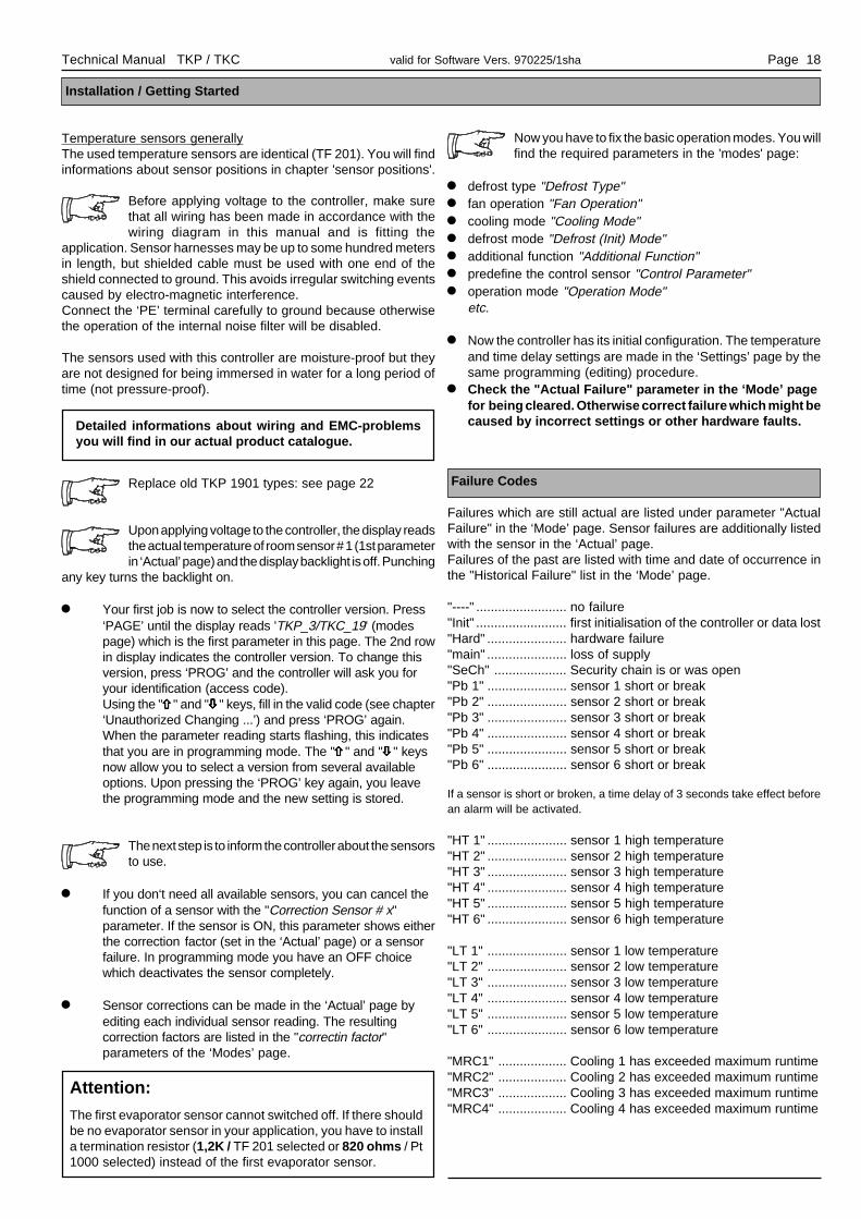
Technical Manual TKP / TKC valid for Software Vers. 970225/1sha Page 18
Installation / Getting Started
Temperature sensors generallyThe used temperature sensors are identical (TF 201). You will findinformations about sensor positions in chapter 'sensor positions'.
Before applying voltage to the controller, make surethat all wiring has been made in accordance with thewiring diagram in this manual and is fitting the
application. Sensor harnesses may be up to some hundred metersin length, but shielded cable must be used with one end of theshield connected to ground. This avoids irregular switching eventscaused by electro-magnetic interference.Connect the ‘PE’ terminal carefully to ground because otherwisethe operation of the internal noise filter will be disabled.
The sensors used with this controller are moisture-proof but theyare not designed for being immersed in water for a long period oftime (not pressure-proof).
Replace old TKP 1901 types: see page 22
Upon applying voltage to the controller, the display readsthe actual temperature of room sensor # 1 (1st parameterin ‘Actual’ page) and the display backlight is off. Punching
any key turns the backlight on.
l Your first job is now to select the controller version. Press‘PAGE’ until the display reads 'TKP_3/TKC_19' (modespage) which is the first parameter in this page. The 2nd rowin display indicates the controller version. To change thisversion, press ‘PROG’ and the controller will ask you foryour identification (access code).Using the "ñññññ" and "òòòòò" keys, fill in the valid code (see chapter‘Unauthorized Changing ...’) and press ‘PROG’ again.When the parameter reading starts flashing, this indicatesthat you are in programming mode. The "ñññññ" and "òòòòò" keysnow allow you to select a version from several availableoptions. Upon pressing the ‘PROG’ key again, you leavethe programming mode and the new setting is stored.
The next step is to inform the controller about the sensorsto use.
l If you don‘t need all available sensors, you can cancel thefunction of a sensor with the "Correction Sensor # x"parameter. If the sensor is ON, this parameter shows eitherthe correction factor (set in the ‘Actual’ page) or a sensorfailure. In programming mode you have an OFF choicewhich deactivates the sensor completely.
l Sensor corrections can be made in the ‘Actual’ page byediting each individual sensor reading. The resultingcorrection factors are listed in the "correctin factor"parameters of the ‘Modes’ page.
Now you have to fix the basic operation modes. You willfind the required parameters in the 'modes' page:
l defrost type "Defrost Type"l fan operation "Fan Operation"l cooling mode "Cooling Mode"l defrost mode "Defrost (Init) Mode"l additional function "Additional Function"l predefine the control sensor "Control Parameter"l operation mode "Operation Mode"
etc.
l Now the controller has its initial configuration. The temperatureand time delay settings are made in the ‘Settings’ page by thesame programming (editing) procedure.
l Check the "Actual Failure" parameter in the ‘Mode’ pagefor being cleared. Otherwise correct failure which might becaused by incorrect settings or other hardware faults.
Failure Codes
Failures which are still actual are listed under parameter "ActualFailure" in the ‘Mode’ page. Sensor failures are additionally listedwith the sensor in the ‘Actual’ page.Failures of the past are listed with time and date of occurrence inthe "Historical Failure" list in the ‘Mode’ page.
"----" ......................... no failure"Init" ......................... first initialisation of the controller or data lost"Hard" ...................... hardware failure"main" ...................... loss of supply"SeCh" .................... Security chain is or was open"Pb 1" ...................... sensor 1 short or break"Pb 2" ...................... sensor 2 short or break"Pb 3" ...................... sensor 3 short or break"Pb 4" ...................... sensor 4 short or break"Pb 5" ...................... sensor 5 short or break"Pb 6" ...................... sensor 6 short or break
If a sensor is short or broken, a time delay of 3 seconds take effect beforean alarm will be activated.
"HT 1" ...................... sensor 1 high temperature"HT 2" ...................... sensor 2 high temperature"HT 3" ...................... sensor 3 high temperature"HT 4" ...................... sensor 4 high temperature"HT 5" ...................... sensor 5 high temperature"HT 6" ...................... sensor 6 high temperature
"LT 1" ...................... sensor 1 low temperature"LT 2" ...................... sensor 2 low temperature"LT 3" ...................... sensor 3 low temperature"LT 4" ...................... sensor 4 low temperature"LT 5" ...................... sensor 5 low temperature"LT 6" ...................... sensor 6 low temperature
"MRC1" ................... Cooling 1 has exceeded maximum runtime"MRC2" ................... Cooling 2 has exceeded maximum runtime"MRC3" ................... Cooling 3 has exceeded maximum runtime"MRC4" ................... Cooling 4 has exceeded maximum runtime
Detailed informations about wiring and EMC-problemsyou will find in our actual product catalogue.
Attention:
The first evaporator sensor cannot switched off. If there shouldbe no evaporator sensor in your application, you have to installa termination resistor (1,2K / TF 201 selected or 820 ohms / Pt1000 selected) instead of the first evaporator sensor.
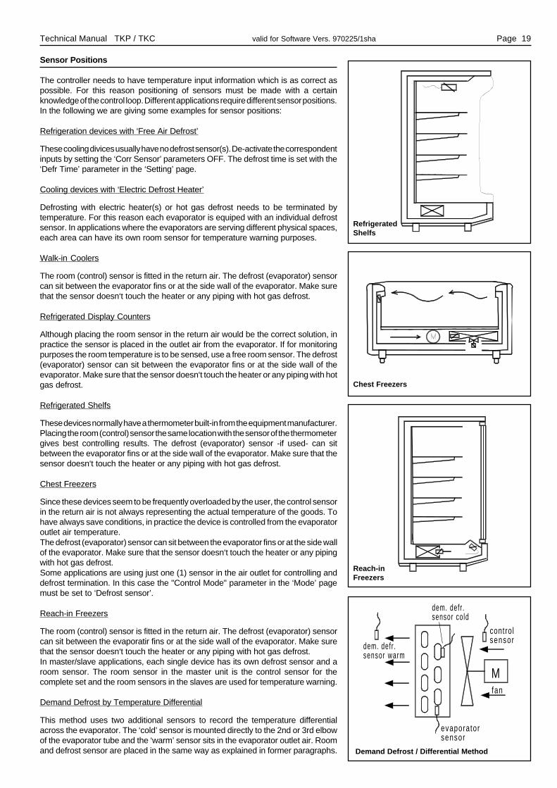
Technical Manual TKP / TKC valid for Software Vers. 970225/1sha Page 19
Sensor Positions
The controller needs to have temperature input information which is as correct aspossible. For this reason positioning of sensors must be made with a certainknowledge of the control loop. Different applications require different sensor positions.In the following we are giving some examples for sensor positions:
Refrigeration devices with ‘Free Air Defrost’
These cooling divices usually have no defrost sensor(s). De-activate the correspondentinputs by setting the ‘Corr Sensor’ parameters OFF. The defrost time is set with the‘Defr Time’ parameter in the ‘Setting’ page.
Cooling devices with ‘Electric Defrost Heater’
Defrosting with electric heater(s) or hot gas defrost needs to be terminated bytemperature. For this reason each evaporator is equiped with an individual defrostsensor. In applications where the evaporators are serving different physical spaces,each area can have its own room sensor for temperature warning purposes.
Walk-in Coolers
The room (control) sensor is fitted in the return air. The defrost (evaporator) sensorcan sit between the evaporator fins or at the side wall of the evaporator. Make surethat the sensor doesn‘t touch the heater or any piping with hot gas defrost.
Refrigerated Display Counters
Although placing the room sensor in the return air would be the correct solution, inpractice the sensor is placed in the outlet air from the evaporator. If for monitoringpurposes the room temperature is to be sensed, use a free room sensor. The defrost(evaporator) sensor can sit between the evaporator fins or at the side wall of theevaporator. Make sure that the sensor doesn‘t touch the heater or any piping with hotgas defrost.
Refrigerated Shelfs
These devices normally have a thermometer built-in from the equipment manufacturer.Placing the room (control) sensor the same location with the sensor of the thermometergives best controlling results. The defrost (evaporator) sensor -if used- can sitbetween the evaporator fins or at the side wall of the evaporator. Make sure that thesensor doesn‘t touch the heater or any piping with hot gas defrost.
Chest Freezers
Since these devices seem to be frequently overloaded by the user, the control sensorin the return air is not always representing the actual temperature of the goods. Tohave always save conditions, in practice the device is controlled from the evaporatoroutlet air temperature.The defrost (evaporator) sensor can sit between the evaporator fins or at the side wallof the evaporator. Make sure that the sensor doesn‘t touch the heater or any pipingwith hot gas defrost.Some applications are using just one (1) sensor in the air outlet for controlling anddefrost termination. In this case the "Control Mode" parameter in the ‘Mode’ pagemust be set to ‘Defrost sensor’.
Reach-in Freezers
The room (control) sensor is fitted in the return air. The defrost (evaporator) sensorcan sit between the evaporatir fins or at the side wall of the evaporator. Make surethat the sensor doesn‘t touch the heater or any piping with hot gas defrost.In master/slave applications, each single device has its own defrost sensor and aroom sensor. The room sensor in the master unit is the control sensor for thecomplete set and the room sensors in the slaves are used for temperature warning.
Demand Defrost by Temperature Differential
This method uses two additional sensors to record the temperature differentialacross the evaporator. The ‘cold’ sensor is mounted directly to the 2nd or 3rd elbowof the evaporator tube and the ‘warm’ sensor sits in the evaporator outlet air. Roomand defrost sensor are placed in the same way as explained in former paragraphs.
Chest Freezers
Demand Defrost / Differential Method
RefrigeratedShelfs
Reach-inFreezers
M
controlsensor
evaporatorsensor
fan
dem. defr.sensor cold
dem. defr.sensor warm

Technical Manual TKP / TKC valid for Software Vers. 970225/1sha Page 20
Failure Locating
This Technical Manual was set up to our best knowledge und we guess having covered all important factors around the ‘TKP 3000’controller.If, nevertheless, you run into problems, we have listed below some common questions which might help you in trouble shooting:
The display shows unreasonable temperature readings:l Check sensors for correct type and connections. Sensors are of same type (TF 201) and should read a resistance value of
2000 Ohms @ 25 °C and 1645 Ohms @ 0 °C.
No regulation functions:l Is the input 'controller off' connected to phase ?l Single compressor versions: Is the security chain open ?
Controller doesn‘t defrost: Check following parameters:l is ‘time of the day’ set correctly ?l are ‘defrost times’ set ? (no defrost at 24:00)l are defrost sensors below ‘defrost temperature’ setting ?l notice that defrost is disabled for 15 minutes after prior defrostl are ‘defr mode’ and ‘defrost type’ set correctly ?l is wiring in accordance with selected mode and type ?l check parameter ‘defrosts ignored’ for number of defrosts to be skipped when optimizing method was selected !
No manual defrost:l check for disabled period (15 minutes after defrost)
Room temperature warm but no cooling:l check for correct setting of ‘cooling mode’ and corresponding wiring connections !l room sensor and defrost sensor mixed up ?l check for active setpoint (day / night) !l if networked: has central unit disabled the solenoid valve ?
Alarm stays ON:l are sensors and wiring correct ?l setpoints and warning offset correct ?l unused sensors switched OFF in ‘sensor correction’ parameter ?
Fan doesn‘t come ON after defrost:l are ‘fan mode’ and ‘defrost mode’ set correctly ?l is ‘fan delay’ set to a reasonable time ?
Defrost is not terminated by temperature:l check for mixed up sensors !l is the defrost sensor(s) activated in ‘sensor correction’ parameter ?l defrost (safety) time set too short ?
Night setpoint (2nd set) active all time:l check OK 1 input (connect to phase and corresponding terminal to neutral) !l check timer settings !
Data lost ( INIT ):l is PE terminal connected to ground ?l sensor leads shielded and shield connected to ground ?l Please check over your installation conditions, informations are available in our actual product catalogue.

Technical Manual TKP / TKC valid for Software Vers. 970225/1sha Page 21
Wiring TKP 3120 / 23120
RS 485 GND
RS 232 OUT
RS 232 IN
RS 232 GND
RS 485 DO
RS 485 NDO
12 40
2227
2824
2526
2317
2120
1819
1613
1415
PROG 50
ELR
EH
A
5556
5152
5354
4
4549
4647
4841
4243
44
1110
98
56
74
31
2 30
23
11
32
3539
3837
3633
3132
34
TK
P-3000
29PE
PE
Mains N
Mains Phase
N/O Relay K1
N/C Relay K1Com Relay K1
N/O Relay K2
N/C Relay K2
Com Relay K2
N/O Relay K3N/C Relay K3
Com Relay K3
N/O Relay K4
N/C Relay K4Com Relay K4
N/O Relay K5
N/C Relay K5
Com Relay K5
N/O Relay K6
N/C Relay K6
Com Relay K6
Control Input OK1 phase
Control Input OK2 phase
Control Input OK3 phaseControl Input OK4 phase
Mains N for OK1/OK2
Mains N for OK3/OK4
PAGE
F ibre Optics Output
Fibre Optics Input
4-20mA Output plus
4-20mA Output minus0-10V Output plus
0-10V Output minus
Input Sensor 6
Input Sensor 5
Gnd for SensorsInput Sensor 4
Input Sensor 3
Input Sensor 2
Input Sensor 1
Gnd for Sensors
2627
2824
2522
23Control Input OK1 phaseControl Input OK2 phase
Control Input OK3 phaseControl Input OK4 phase
Mains N for OK1/OK2
Mains N for OK3/OK4
5055
5651
5253
5449
48
Sensors TF 201
! don't forget !
PAGE
Outline DimensionsTKP 3120 / 23120
153 (6.02)
1 32 1 2 3 4
TKP-3000
35 (
1.38
)
114
(4.4
9)
47 (
1.85
)
ELREHA
P R O G
LIST
93 (
3.66
)
63 (
2.48
)
59 (2.32)39 (1.54)
26 (1.02)

Technical Manual TKP / TKC valid for Software Vers. 970225/1sha Page 22
Wiring TKC 19120 / 29120
Wiring of sensors and optocoupler inputs Rear View
DIN 41612 'F' connectors, rear view.The terminal numbers shown above are used inELREHA pre-wired subracks.
Note: If you want to replace an older controller ofthe TKP 1901 series, please change parameter"TKP 1901_Emulat." to "ON" and select a versionnumber (see table right). So the relay output will bechanged equivalent to the old controller types.The new functions are located on pins which werenot connected at the old TKP's.If the new features should be used, the wiring mustonly be completed.
Outline Dimensions TKC 19120 / 29120
4
1
70,8 (2.76)
129
(5.0
8)
P R O G
65
32
LIST
TMC-19"
110
(4.3
3)
166 (6.54)2,5 (.1)
E L R E H A
12
42
10
68
3028
2220181614
2426
32
25
29
33
31
27
37
4139
PE
42
68
RS-485
RS-232
26
1210
2220181614
24
3028
32
DO
NDO
IN
OUT
GND
3024
3234
2628
3230
43
26
28
44
42
40
38
23
24
d21 1
8
22
1012
20181614
46
L2
d
N242628
3230
8
22
10
14
201816
12
PE46
N N2
z
terminal terminal terminal terminalana log PCB power PCB
Relay 1
Relay 2
Relay 3
Relay 4
Relay 5
Relay 6
4/20mA Outp.Input /Sensor 6Input /Sensor 5
0/10V OutputInput /Sensor 4Input /Sensor 3Input /Sensor 2Input /Sensor 1
10
4
7
47
16
OK3OK1 OK2
O K 449
48
13
8
9
23
5
6
4546
14
15
17
181112
N
Replacing old TKP controllers
Old TKP
1901
version
New TKC-
version
Set parameter
"TKP_3/TKC_19" to
A TKC 19120 A
C TKC 19120 C
D TKC 19120 C
E TKC 19120 E
F TKC 19120 F
G TKC 19120 F
Relay positions TKP 1901
Vers. Relay 1 Relay 2 Rel. 3 Relay 4 Relay 5
A Cooling1 Cooling 2 Alarm Defrost 1 Defrost 2
C Cooling Rollerblind Alarm Defrost 1 Defrost 2
D Cooling Frameheater Alarm Defrost 1 Defrost 2
E Cooling Fan Alarm Defrost 1 Defrost 2
F Cooling Fan Alarm Defrost Rollerblind
G Cooling Fan Alarm Defrost Frameheater
z d
analog pcb
d z
power pcb
OK 2 OK 3
Control inputspower pcb
OK 1
d28
d26
z26
z28
OK 4z24
Mains N
analog PCB
z
PE
12
d
642
810
2-wire connection
181614
242220
2826
3032
Technical Manual TKP / TKC valid for Software Vers. 970225/1sha Page 23
Inputs and Outputs of the settable Versions
Relays Optocoupler Inputs Temperature Sensors
Relay 1 Relay 2 Relay 3 Relay 4 Relay 5 Relay 6 OK 1 OK 2 OK 3 OK 4 Sensor 1 Sensor 2 Sensor 3 Sensor 4 Sensor 5 Sensor 6
A Alarm Cooling 1 Cooling 2Roller bl./
Frameheater
Defrost 2 Defrost 1RemoteDefrost
phase=day
mode
ControlOFF
-----Room
Sensor 1Defrost
Sensor 1Room Sensor
2Defrost
Sensor 2----- 'Shop' Sensor
C Alarm Cooling 1Roller bl./
Frameheater
Defrost 3 Defrost 2 Defrost 1RemoteDefrost
phase=day
mode
ControlOFF
-----Room
Sensor 1Defrost
Sensor 1
Display /WarningSensor 2
DefrostSensor2
Display /WarningSensor 3
DefrostSensor 3
E Alarm Cooling 1 Fan Defrost 3 Defrost 2 Defrost 1RemoteDefrost
phase=day
mode
ControlOFF
-----Room
Sensor 1Defrost
Sensor 1
Display /WarningSensor 2
DefrostSensor 2
Display /WarningSensor 3
DefrostSensor 3
F Alarm Cooling 1 FanRoller bl./
Frameheater
Defrost 2 Defrost 1RemoteDefrost
phase=day
mode
ControlOFF
-----Room
Sensor 1Defrost
Sensor 1
Display /WarningSensor 2
DefrostSensor 2
Demand Defr.Sensor Cold
Demand Defr.Sensor Warm
I Alarm Cooling 1 Cooling 2Roller bl./
Frameheater
Cooling 4 Cooling 3RemoteDefrost
phase=day
mode
ControlOFF
-----Air OutletSensor 1
Air OutletSensor 2
Air OutletSensor 3
Air OutletSensor 4
'Shop' SensorAlarm Sensor
Air Inlet
K Alarm Cooling 1 Cooling 2Roller bl./
Frameheater
----- -----RemoteDefrost
phase=day
mode
ControlOFF
-----Control
Sensor PilotElement
Evap.SensorPilot
Element
ControlSensor Single
Element
EvaporatorSensor
Single Elem
Evap.SensorAdd. Elem. 1
Evap.SensorAdd. Elem. 2
L Alarm Cooling 1 Cooling 2Roller bl./
Frameheater
----- Cooling 3RemoteDefrost
phase=day
mode
ControlOFF
-----Room
Sensor 1Defrost
Sensor 1Room Sensor
2Defrost
Sensor 2Room Sensor
3Defrost
Sensor 3
M AlarmSol.Valveor Compr.
Roller bl./Frameheater
Defrost 3 Defrost 2 Defrost 1RemoteDefrost
phase=day
mode
ControlOFF
Securitychain:
phase=ok
RoomSensor 1
DefrostSensor 1
Display /WarningSensor 2
DefrostSensor 2
Display /WarningSensor 3
DefrostSensor 3
N AlarmSol.Valveor Compr.
Fan Defrost 3 Defrost 2 Defrost 1RemoteDefrost
phase=day
mode
ControlOFF
Securitychain:
phase=ok
RoomSensor 1
DefrostSensor 1
Display /WarningSensor 2
DefrostSensor 2
Display /WarningSensor 3
DefrostSensor 3
Outline Dimensions TKC 5120 / 25120
225
3940
261
14151617181920212223243 4 5 6 7 8 9 1110 12 13
27282930313233343536373841 42 43 44 45 46 47 48 49 50 51 52
P R O G4
ELREHA
2
3
1LIST
8
6
7
5
95 (
3.74
)
89,5
(3.
52)
95 (3.74) 133 (5.24) 8 (.31)
!
sens
or 1
sens
or 2
sens
or 3
sens
or 4
sens
or 5
sens
or 6
21121 27
N
2 14 10 11 42413 2526 6 5
31
OK
2
OK
3
OK
4
F 5
F 6
5152 50
L
3
F 5
30
TKC 5120 / 25120
Relay 1 Relay 2OK
1F
6
F 5
484932
F 6
4647 33
152223 192018 79 8 17 16
38
R S232
Relay 3 Relay 4 Relay 5IN
3734 35 36
GN
D
39
0...
10V
Out
put
4.. .
20m
AO
utpu
t
Re lay 6
OU
T
DO
ND
O
R S485
44 45

Technical Manual TKP / TKC valid for Software Vers. 970225/1sha Page 24
set-up: 24.2.98 checked: 24.2.98 approved: 24.2.98
by: tkd/jr by: tkd/mh by: mv/sha
Accessories
- Temperature sensor TF 201or TF 501 (Pt 1000)- PC-software COOLVision for data recording and remote control
*The conformity with IEC 1000-4-3 is derived from the IEC 1000-4-2 and IEC 1000-4-4 test results. The correlation with IEC 1000-4-3 is based ontest results which are located on site at the manufacturer.
We state the following: When operated in accordance with the technical manual, the criteria have been met that are outlined in the guidelines of thecouncil for alignment of statutory orders of the member states on electro-magnetic consistency. ( 89/336/EWG ) This declaration is valid for thoseproducts covered by the technical manual which itself is part of the declaration.Following standards were consulted for the confirmity testing with regard to electromagnetic consistency :IEC 1000-4-1, IEC 1000-4-2, IEC 1000-4-3*, IEC 1000-4-4, IEC 1000-4-5, EN 55011 B, EN 50081, Teil 1 und 2; EN 50082, Teil 1 und 2
This statement is made from the manufacturer / importer by:
ELREHA Elektronische Regelungen GmbH Klaus Birkner, ....................................................................................D-68766 Hockenheim, Germany Development and Leader of the EMC-Laboratory ..............(name / adress)
Hockenheim .............18.12.95.......................................................city date sign
EG-Statement of Conformity
This manual has been set up with care and to our best knowledge, but mistakes are still possible. Technical details, especially the software, canbe changed without notice. Please note that this manual is only valid for controllers who are containing the software-version shown on page 1. Thisversion-number is also displayed in the mode page (parameter 'Program Version'). If you have still problems or difficulties or questions please don´thesitate asking our technical support. Called trademarks are properties of their companies.
Available Types
TKP 3120 .......... Plastic housing, for 35 mm DIN-rail, IP 30,dust-proof keyboard, 230V, german language
TKP 3120 E ....... same housing, 230V, english languageTKP 23120 ........ same housing, 115V / 60Hz, english languageTKC 5120 .......... Plastic housing, 96x96mm for panel mounting,
IP 54 from front, 230V, german languageTKC 5120 E ....... same housing, 230V, english languageTKC 25120 ........ same housing, 115V / 60Hz, english languageTKC 19120 ........ 19"-module, IP 30, 230V, german languageTKC 19120 E ..... 19"-module, IP 30, 230V, english languageTKC 29120 ........ 19"-module, IP 30, 115V/60Hz, german language
Ask for types with Solid State relay outputs and/or fibre opticsinterface.