Embed Size (px)
Citation preview
7/23/2019 Elekta Synergy - Flex Map
http://slidepdf.com/reader/full/elekta-synergy-flex-map 1/8
S T E R E O T A C T I C R A D I A T I O N T H E R A P Y
Elekta Synergy® S
High precision radiation therapy using
Elekta Synergy® S
Institution: UMC, Utrecht, Netherlands
Purpose:
The primary application of Elekta Synergy® S
at UMC, Utrecht, is frameless intracranial high
precision radiation therapy, using multi or single
fraction, static or arc techniques. A convergent beam
irradiation(3) technique is used to treat patients
on this machine, using XVI and 3D VolumeViewTM
imaging to verify the patient position, correct the
table position and then reconfirm the new position.
Accuracy study
7/23/2019 Elekta Synergy - Flex Map
http://slidepdf.com/reader/full/elekta-synergy-flex-map 2/8
High precision radiation therapy using
Elekta Synergy® S
Elekta Synergy® S commissioning team
Marjolein Baarda Gijsbert Bol Minique Boere Arther van Bruggen
Corine van Es Fred Groen Mark Harms Erick Kouwenhoven
Stephen Kwa Rogier Schokker Theo van Soest Ties Timmers
Gitta van Vliet Eric Westzaan Hans Welleweerd Andre Wopereis
Acceptance tests were performed on the following items to ensure the suitability of Elekta Synergy® S for the job in hand.
• Mechanical/geometrical accuracy – tolerance 0.5mm
• Field definition: strip test/calibration
• Rotational accuracy of diaphragm/collimator, gantry and table
Sources of errors such as mechanical sag or misalignments are addressed.
Method and results
BEAM MODULATOR TM
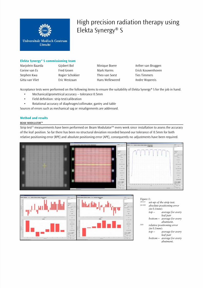
Strip test(1) measurements have been performed on Beam ModulatorTM every week since installation to assess the accuracy
of the leaf position. So far there has been no structural deviation recorded beyond our tolerance of 0.5mm for both
relative positioning error (RPE) and absolute positioning error (APE), consequently no adjustments have been required.
Figure 1:(above) set-up of the strip test.(far left) absolute positioning error
(in 0.1mm): top – average for every
leaf pair bottom – average for every
abutment.(left) relative positioning error
(in 0.1mm): top – average for every leaf pair bottom – average for every abutment.
7/23/2019 Elekta Synergy - Flex Map
http://slidepdf.com/reader/full/elekta-synergy-flex-map 3/8
COLLIMATOR ROTATION
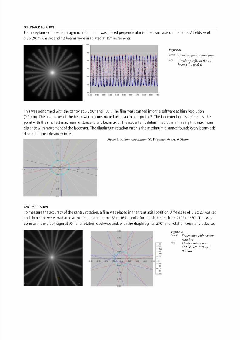
For acceptance of the diaphragm rotation a film was placed perpendicular to the beam axis on the table. A fieldsize of
0.8 x 20cm was set and 12 beams were irradiated at 15° increments.
Figure 2:
(far left) a diaphragm rotation film
(left) circular profile of the 12beams (24 peaks)
This was performed with the gantry at 0°, 90° and 180°. The film was scanned into the software at high resolution
(0.2mm). The beam axes of the beam were reconstructed using a circular profile(2). The isocenter here is defined as ‘the
point with the smallest maximum distance to any beam axis’. The isocenter is determined by minimizing this maximum
distance with movement of the isocenter. The diaphragm rotation error is the maximum distance found: every beam-axis
should hit the tolerance circle.
Figure 3: collimator rotation 10MV gantry 0: dev. 0.08mm
GANTRY ROTATION
To measure the accuracy of the gantry rotation, a film was placed in the trans axial position. A fieldsize of 0.8 x 20 was set
and six beams were irradiated at 30° increments from 15° to 165°, and a further six beams from 210° to 360°. This was
done with the diaphragm at 90° and rotation clockwise and, with the diaphragm at 270° and rotation counter-clockwise.
Figure 4:(far left) Spoke film with gantry
rotation(left) Gantry rotation ccw.
10MV coll. 270: dev.0.38mm
7/23/2019 Elekta Synergy - Flex Map
http://slidepdf.com/reader/full/elekta-synergy-flex-map 4/8
TABLE ROTATION
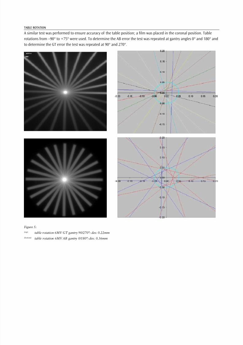
A similar test was performed to ensure accuracy of the table position; a film was placed in the coronal position. Table
rotations from –90° to +75° were used. To determine the AB error the test was repeated at gantry angles 0° and 180° and
to determine the GT error the test was repeated at 90° and 270°.
Figure 5:
(top) table rotation 6MV GT gantry 90/270°: dev. 0.22mm
(bottom) table rotation 6MV AB gantry 0/180°: dev. 0.36mm
7/23/2019 Elekta Synergy - Flex Map
http://slidepdf.com/reader/full/elekta-synergy-flex-map 5/8
GANTRY SAG
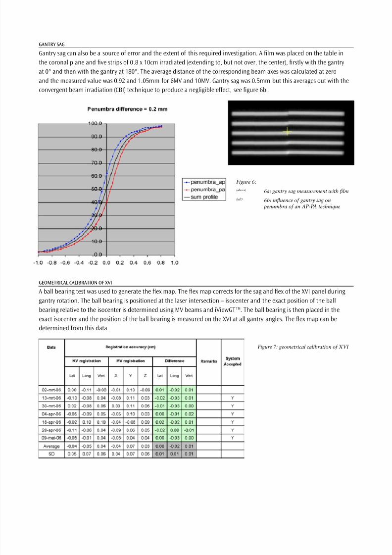
Gantry sag can also be a source of error and the extent of this required investigation. A film was placed on the table in
the coronal plane and five strips of 0.8 x 10cm irradiated (extending to, but not over, the center), firstly with the gantry
at 0° and then with the gantry at 180°. The average distance of the corresponding beam axes was calculated at zero
and the measured value was 0.92 and 1.05mm for 6MV and 10MV. Gantry sag was 0.5mm but this averages out with the
convergent beam irradiation (CBI) technique to produce a negligible effect, see figure 6b.
Figure 7: geometrical calibration of XVI
Figure 6:
(above) 6a: gantry sag measurement with film
(left) 6b: influence of gantry sag on penumbra of an AP-PA technique
GEOMETRICAL CALIBRATION OF XVI
A ball bearing test was used to generate the flex map. The flex map corrects for the sag and flex of the XVI panel duringgantry rotation. The ball bearing is positioned at the laser intersection – isocenter and the exact position of the ball
bearing relative to the isocenter is determined using MV beams and iViewGTTM. The ball bearing is then placed in the
exact isocenter and the position of the ball bearing is measured on the XVI at all gantry angles. The flex map can be
determined from this data.
7/23/2019 Elekta Synergy - Flex Map
http://slidepdf.com/reader/full/elekta-synergy-flex-map 6/8
XVI IMAGE QUALITY
The CATPHAN phantom is used to measure the image quality of the Elekta Synergy® S kV images on both contrast and
detail resolution. Detail >7lp/_cm_ and low contrast value < 2%.
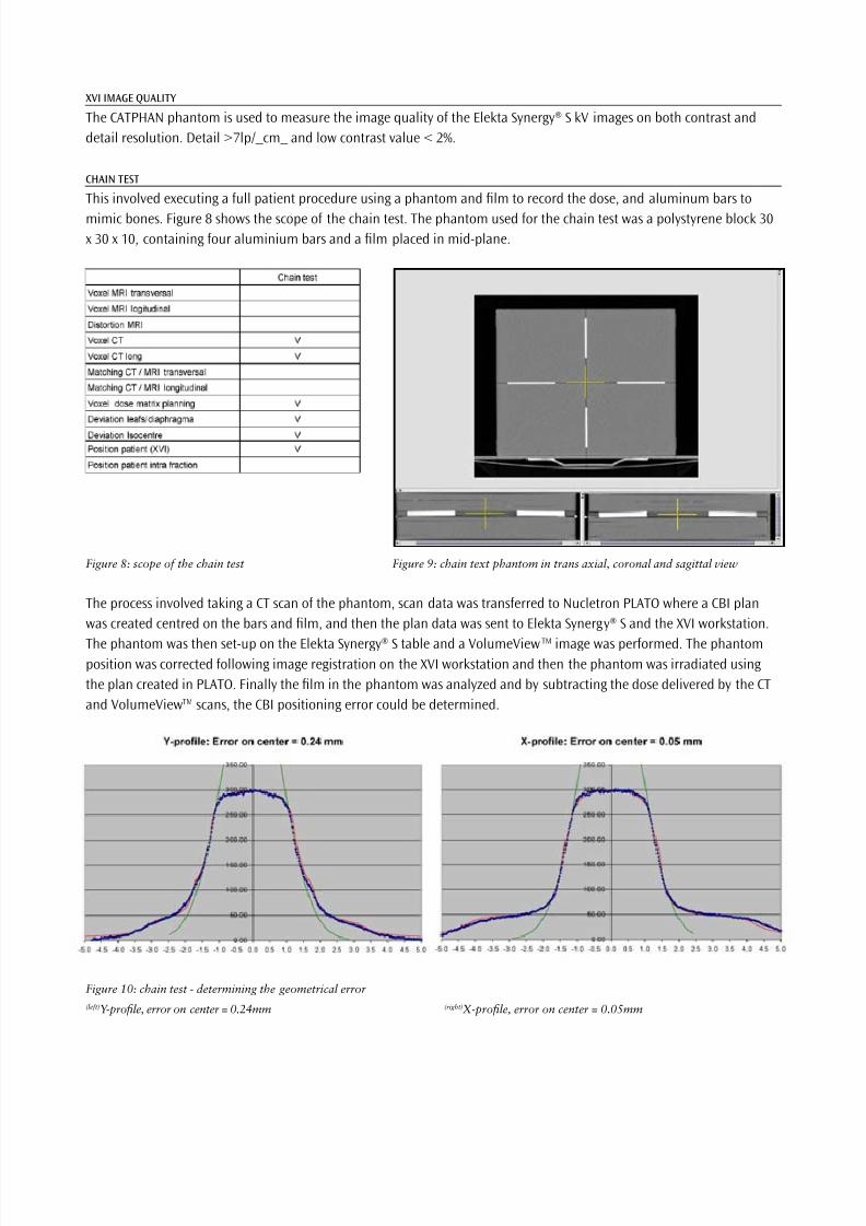
CHAIN TEST
This involved executing a full patient procedure using a phantom and film to record the dose, and aluminum bars to
mimic bones. Figure 8 shows the scope of the chain test. The phantom used for the chain test was a polystyrene block 30
x 30 x 10, containing four aluminium bars and a film placed in mid-plane.
Figure 8: scope of the chain test Figure 9: chain text phantom in trans axial, coronal and sagittal view
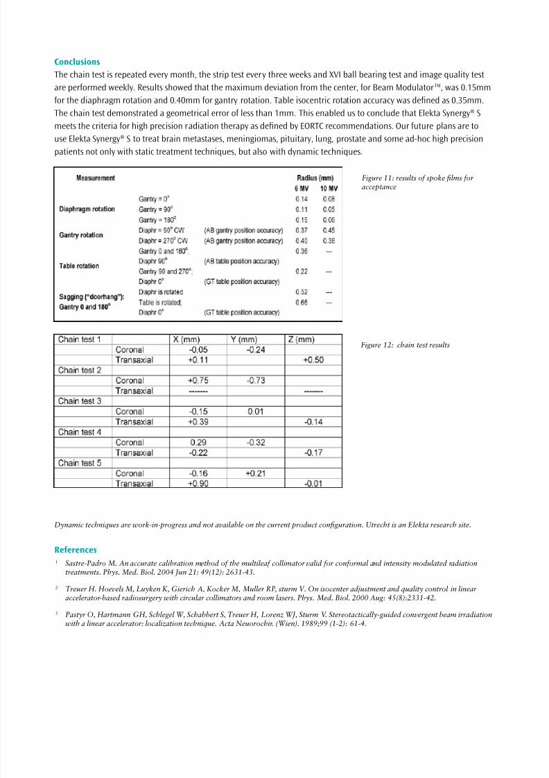
The process involved taking a CT scan of the phantom, scan data was transferred to Nucletron PLATO where a CBI plan
was created centred on the bars and film, and then the plan data was sent to Elekta Synergy® S and the XVI workstation.
The phantom was then set-up on the Elekta Synergy® S table and a VolumeViewTM image was performed. The phantomposition was corrected following image registration on the XVI workstation and then the phantom was irradiated using
the plan created in PLATO. Finally the film in the phantom was analyzed and by subtracting the dose delivered by the CT
and VolumeViewTM scans, the CBI positioning error could be determined.
Figure 10: chain test - determining the geometrical error
(left)Y-profile, error on center = 0.24mm (right)X-profile, error on center = 0.05mm
7/23/2019 Elekta Synergy - Flex Map
http://slidepdf.com/reader/full/elekta-synergy-flex-map 7/8
Conclusions
The chain test is repeated every month, the strip test every three weeks and XVI ball bearing test and image quality test
are performed weekly. Results showed that the maximum deviation from the center, for Beam ModulatorTM, was 0.15mm
for the diaphragm rotation and 0.40mm for gantry rotation. Table isocentric rotation accuracy was defined as 0.35mm.
The chain test demonstrated a geometrical error of less than 1mm. This enabled us to conclude that Elekta Synergy® S
meets the criteria for high precision radiation therapy as defined by EORTC recommendations. Our future plans are to
use Elekta Synergy® S to treat brain metastases, meningiomas, pituitary, lung, prostate and some ad-hoc high precision
patients not only with static treatment techniques, but also with dynamic techniques.
Figure 12: chain test results
Figure 11: results of spoke films foracceptance
Dynamic techniques are work-in-progress and not available on the current product configuration. Utrecht is an Elekta research site.
References1 Sastre-Padro M. An accurate calibration method of the multileaf collimator valid for conformal and intensity modulated radiation
treatments. Phys. Med. Biol. 2004 Jun 21: 49(12): 2631-43.
2 Treuer H. Hoevels M, Luyken K, Gierich A, Kocker M, Muller RP, sturm V. On isocenter adjustment and quality control in linearaccelerator-based radiosurgery with circular collimators and room lasers. Phys. Med. Biol. 2000 Aug: 45(8):2331-42.
3 Pastyr O, Hartmann GH, Schlegel W, Schabbert S, Treuer H, Lorenz WJ, Sturm V. Stereotactically-guided convergent beam irradiationwith a linear accelerator: localization technique. Acta Neuorochir. (Wien). 1989;99 (1-2): 61-4.

7/23/2019 Elekta Synergy - Flex Map
http://slidepdf.com/reader/full/elekta-synergy-flex-map 8/8
Corporate Head Office
Stockholm, SwedenTel +46 8 587 254 00
Fax +46 8 587 255 [email protected]
Worldwide Product
Support Center
Tel +44 01293 654068
Fax +44 01293 [email protected]
North America
Atlanta, USATel +1 770 300 9725
Fax +1 770 448 [email protected]
Europe, South America,
Africa & the Middle East
Tel +44 1293 654068
Fax +44 1293 [email protected]
Japan
Kobe, JapanTel +81 78 241 7100
Fax +81 78 271 [email protected]
Asia-Pacific
Hong Kong, ChinaTel +852 2891 2208
Fax +852 2575 [email protected]
nStereotactic Neurosurgery nGamma Knife® surgery nFunctional Mapping nPrecision Radiation Therapy nImage Guided Radiation Therapy nStereotactic Radiation Therapy
Fighting serious disease www.elekta.com
D o c u
m e n t N o .
4 5 1 3 3 7 1 0 6 5 4 0 8 : 0 6 ©
2 0 0 6 E l e k t a L t d .
A l l m e n t i o n e d E l e k t a t r a d e m a r k s a n d r e g i s t e r e d t r a d e m a r k s a r e t h e p r o p e r t y o f E l e k t a A B ( p u b l ) a n d /
o r i t s s u b s i d i a r i e s . N u c l e t r o n P L A T O i s a t r a d e m a r k o f N u c l e t r o n B V .
A l l r i g h t s r e s e r v e d .
N o p a r t o f t h i s d o c u m e n t m a y b e r e p r o d u c e d i n a n y f o r m
w i t h o u t w r i t t e n p e r m i s s i o n f r o m
t h e c o p y r i g h t h o l d e r .
S p e c i fi c a t i o n s s u b j e c t t o c h a n g e w i t h o u t n o t i c e .