Embed Size (px)
Citation preview
ELEG 479Lecture #8
Mark Mirotznik, Ph.D.Associate Professor
The University of Delaware
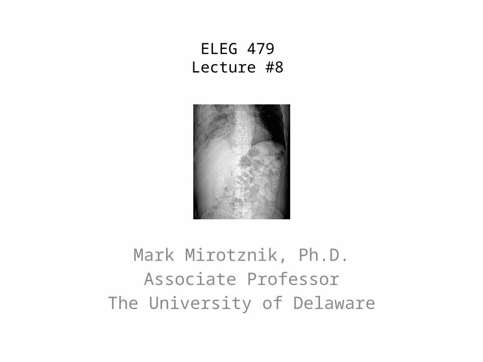
Summary of Last LectureX-ray Radiography
Overview of different systems for projection radiography Instrumentation
Overall system layout X-ray sources grids and filters detectors
Imaging Equations Basic equations Geometrical distortions More complicated imaging equations

Hounsfield’s Experimental CT
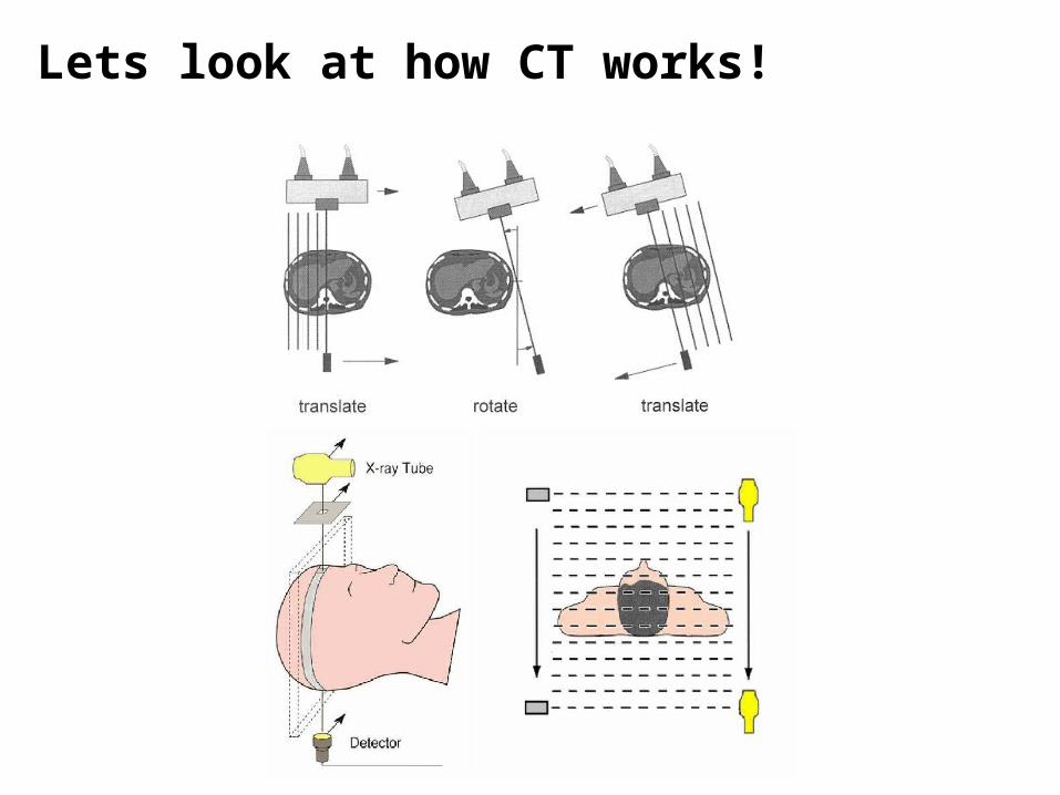
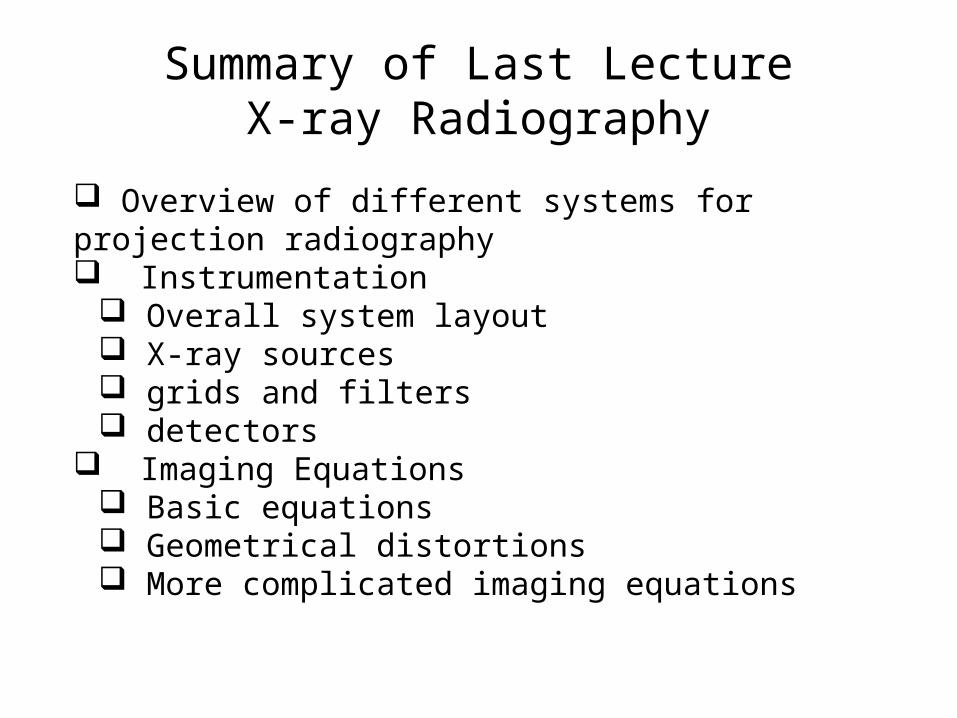
Lets look at how CT works!
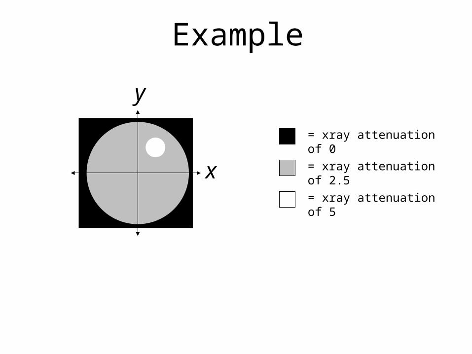
x
y
= xray attenuation of 2.5
= xray attenuation of 5
= xray attenuation of 0
Example
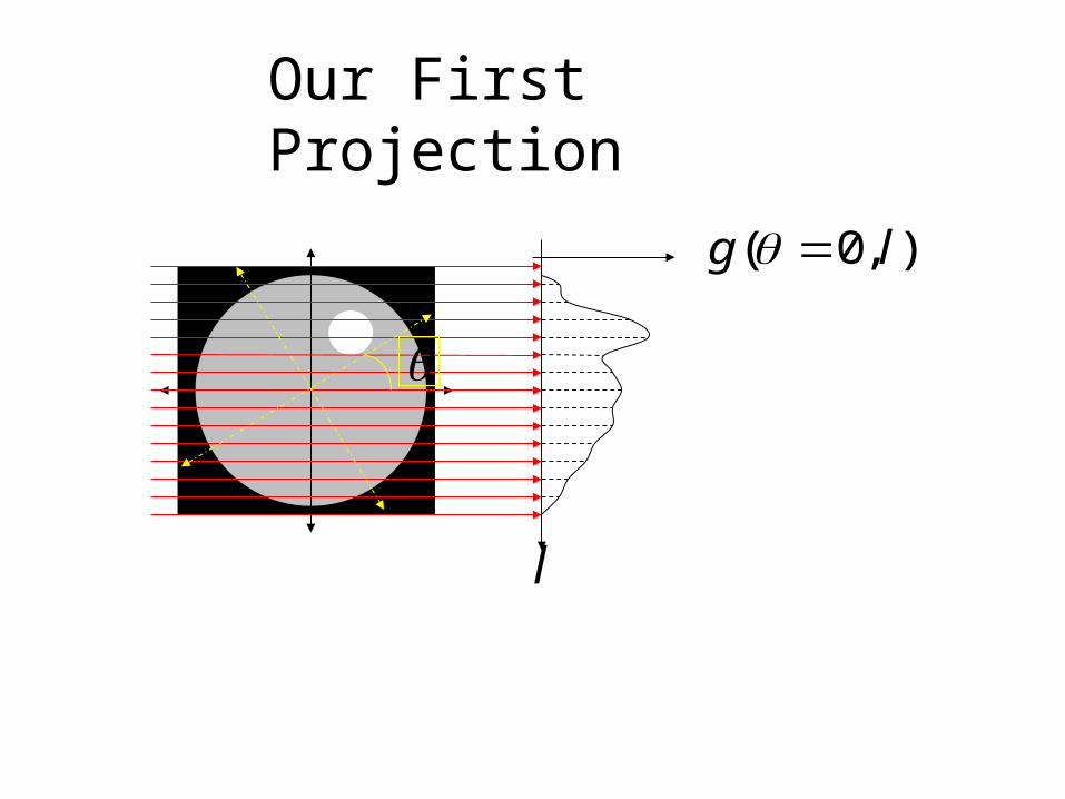
l
),0( lg
Our First Projection
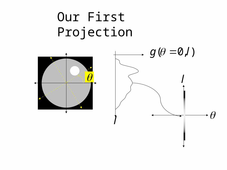
Our First Projection
l
),0( lg
l
l
45o
l
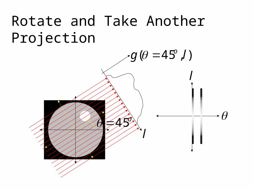
),45( lg o
Rotate and Take Another Projection
l
90ol
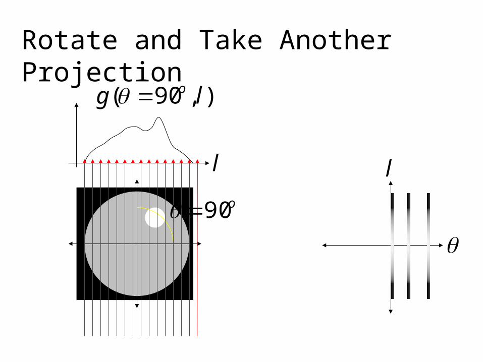
),90( lg o
Rotate and Take Another Projection
l
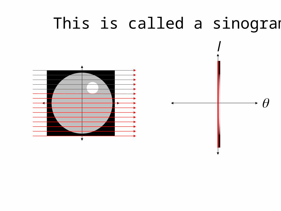
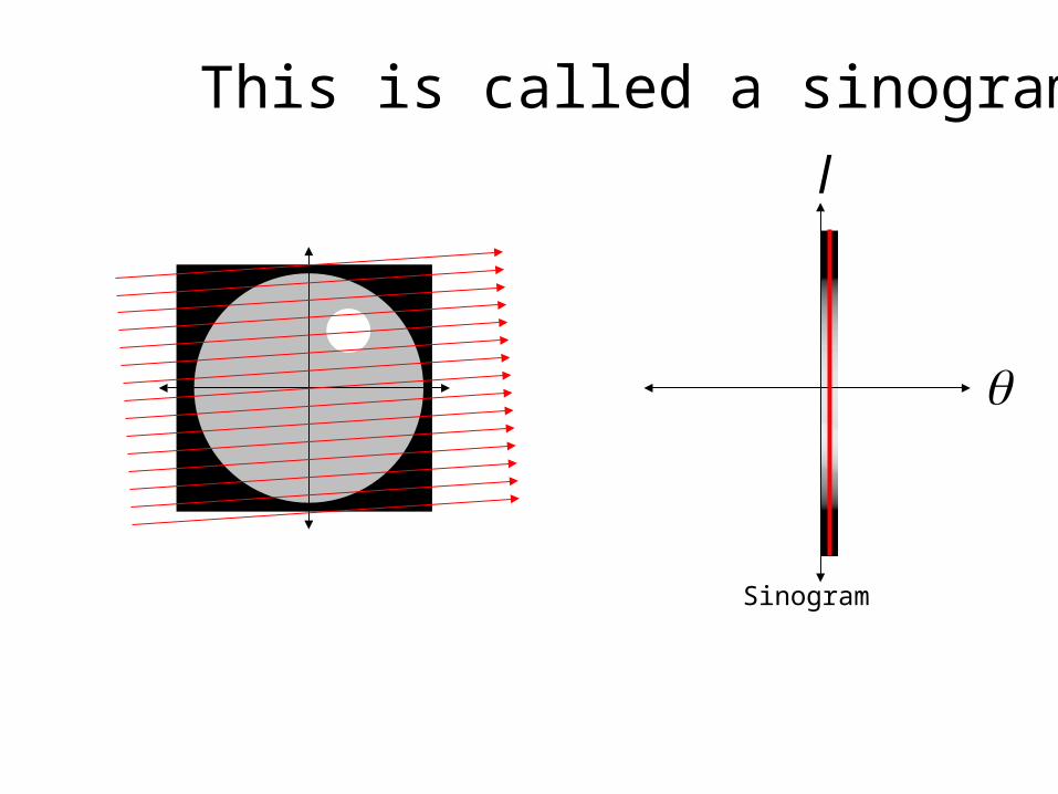
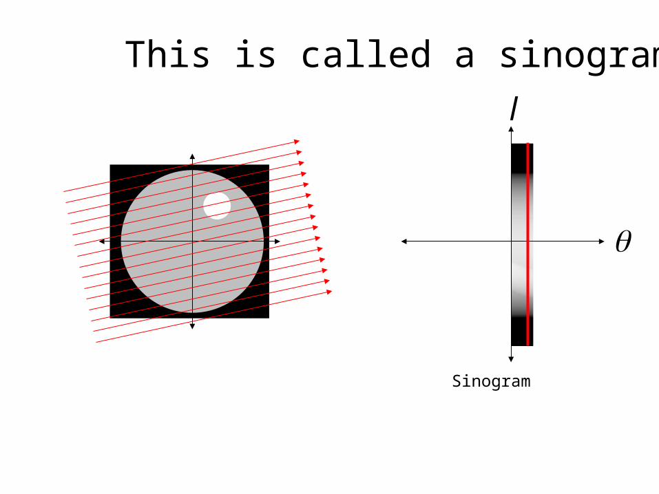
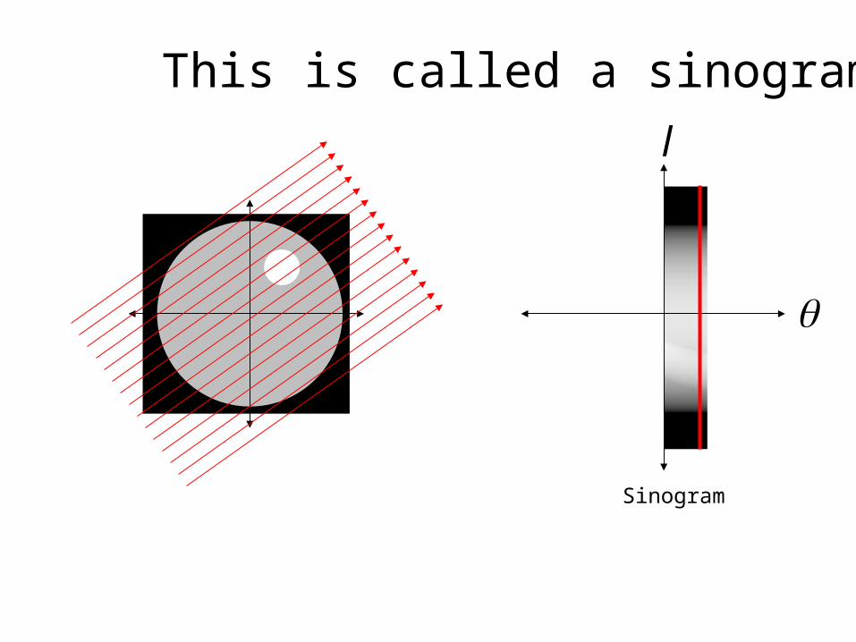
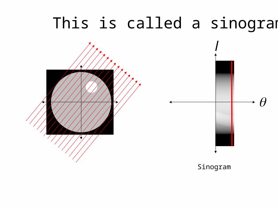
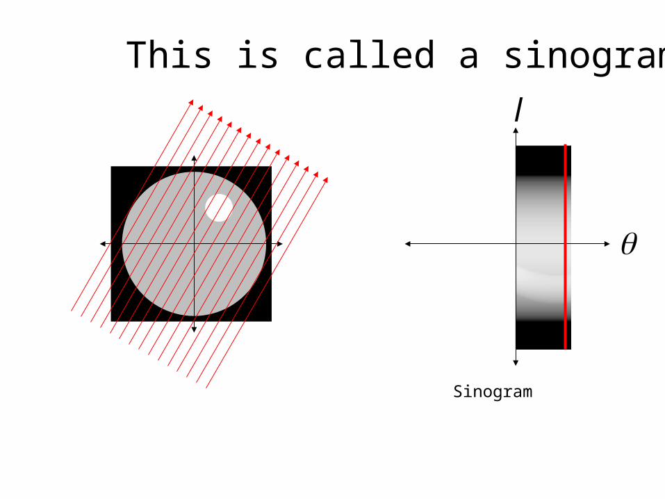
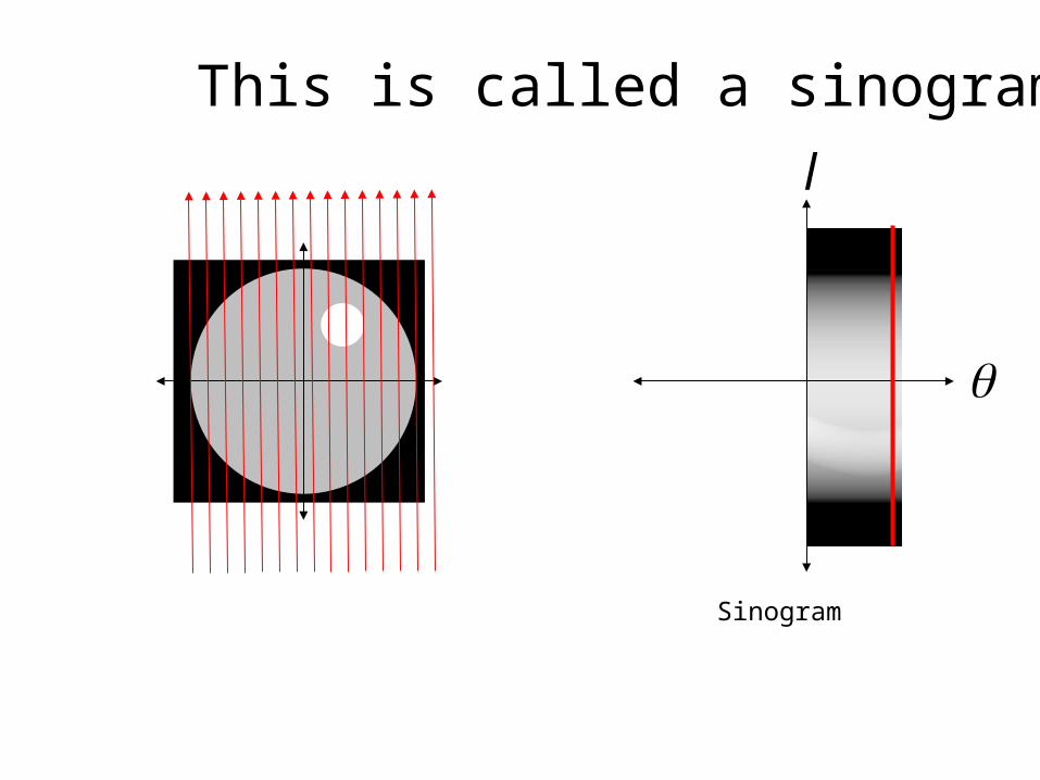
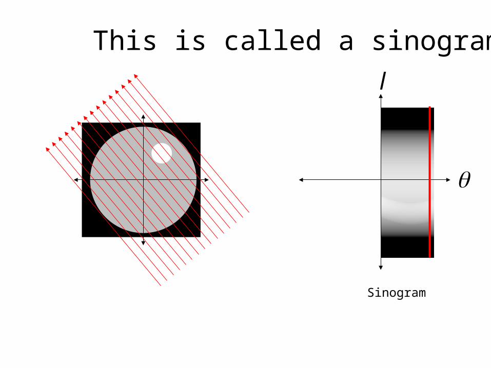
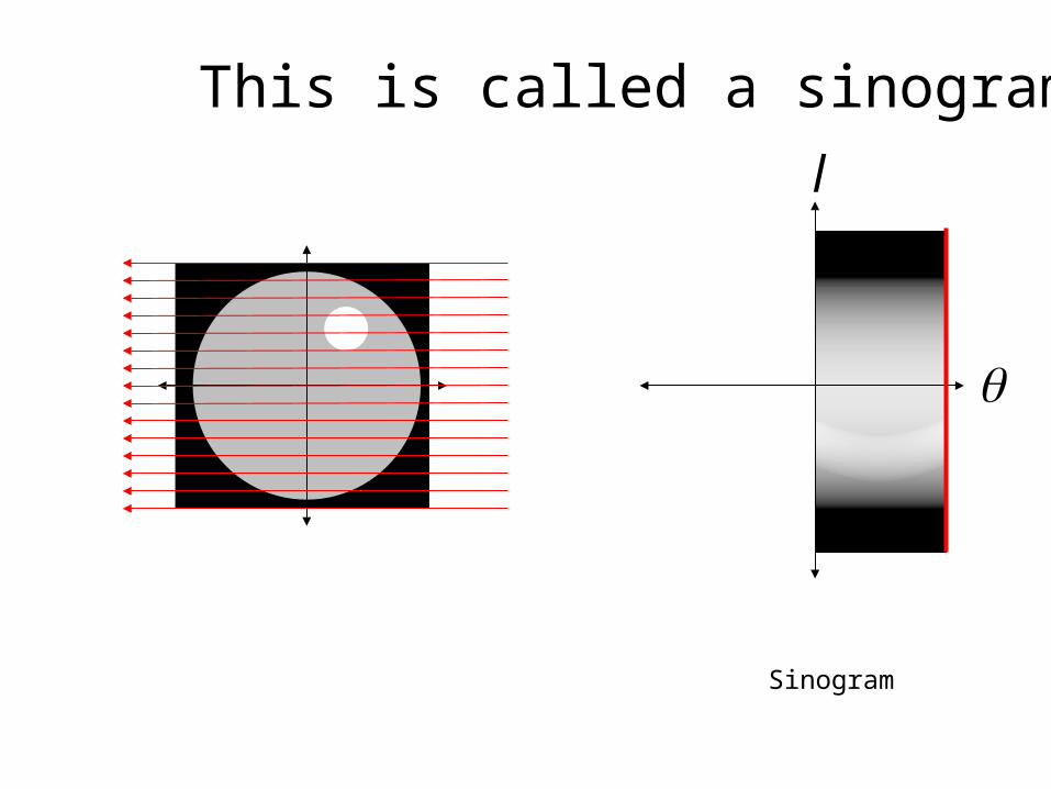
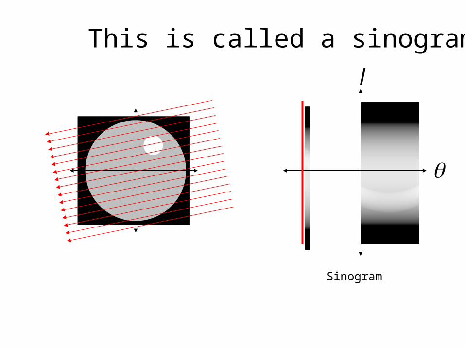
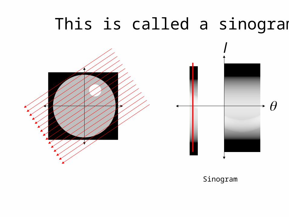
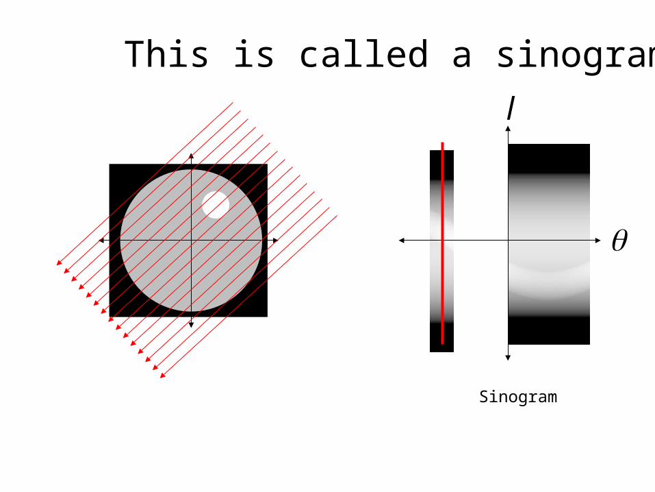
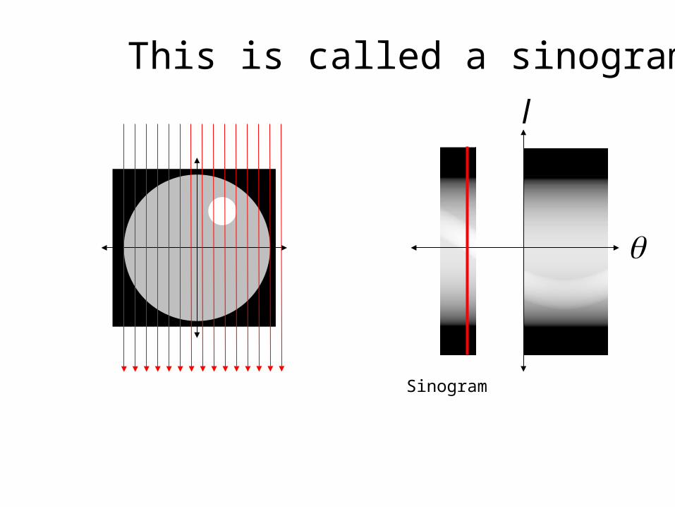
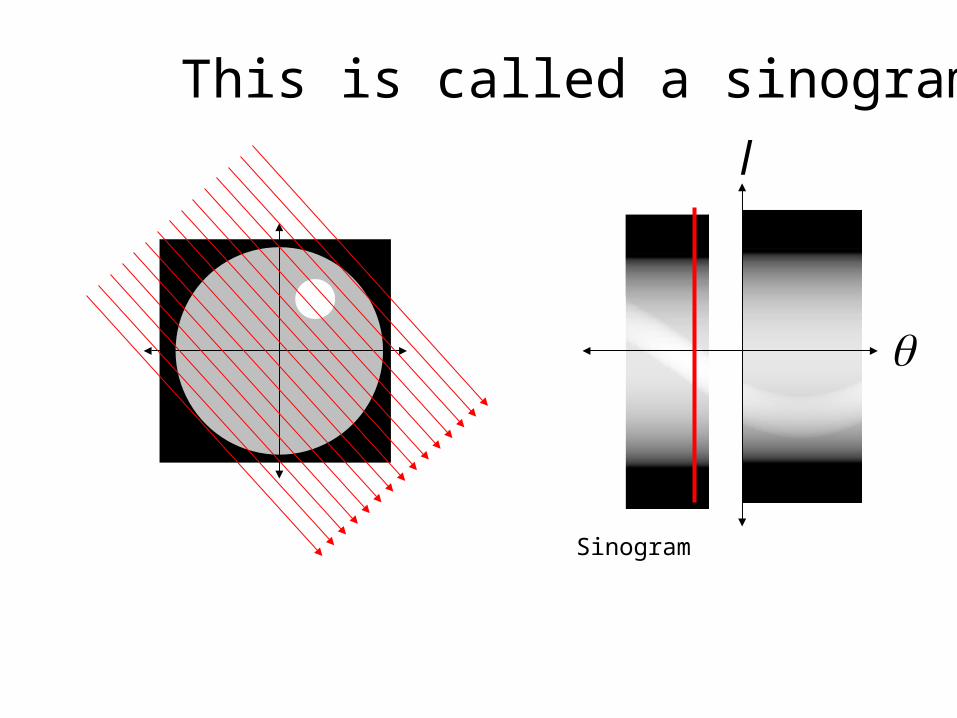
This is called a sinogram
Sinogram
l
This is called a sinogram
Sinogram
l
This is called a sinogram

Sinogram
l
This is called a sinogram
Sinogram
l
This is called a sinogram
Sinogram
l
This is called a sinogram
Sinogram
l
This is called a sinogram
Sinogram
l
This is called a sinogram
Sinogram
l
This is called a sinogram
Sinogram
l
This is called a sinogram
Sinogram
l
This is called a sinogram

Sinogram
l
This is called a sinogram
Sinogram
l
This is called a sinogram
Sinogram
l
This is called a sinogram
Sinogram
l
This is called a sinogram
Sinogram
l
This is called a sinogram

Sinogram
l
This is called a sinogram
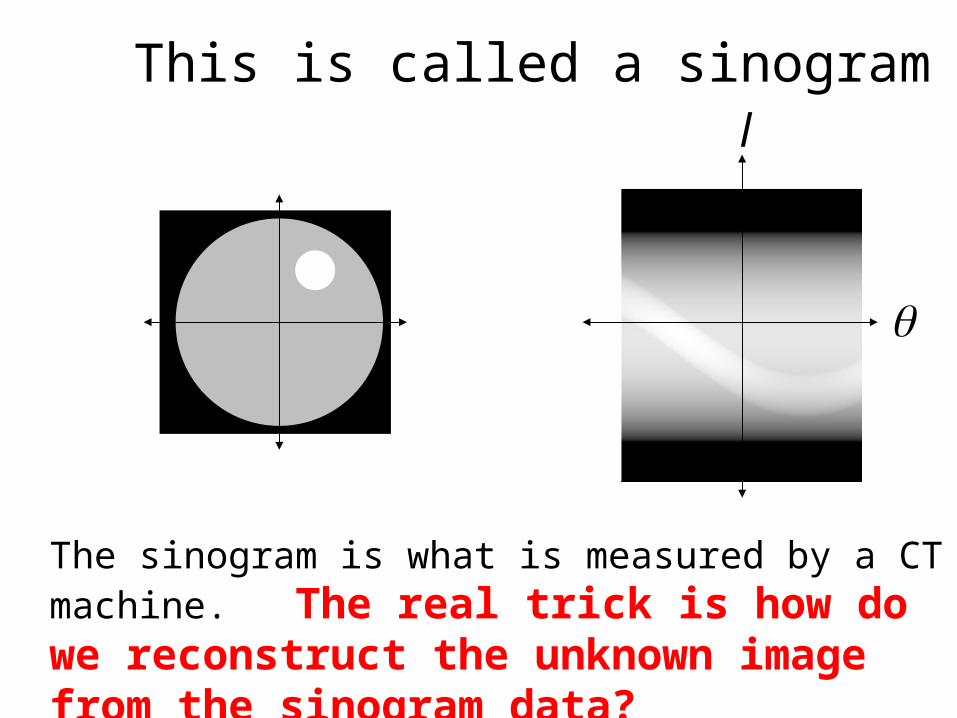
The sinogram is what is measured by a CT machine. The real trick is how do we reconstruct the unknown image from the sinogram data?
l
This is called a sinogram
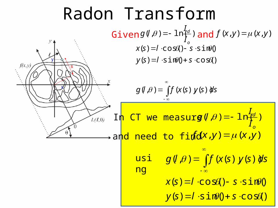
Radon Transform)ln(),(
o
d
I
Ilg Given and ),(),( yxyxf
dssysxflg
slsy
slsx
))(),((),(
)cos()sin()(
)sin()cos()(
In CT we measure )ln(),(o
d
I
Ilg
and need to find ),(),( yxyxf
)cos()sin()(
)sin()cos()(
))(),((),(
slsy
slsx
dssysxflgusing

Radon Transform
In CT we measure ),( lg
and need to find ),( yxf
We use
dxdylyxyxflg )sincos(),(),(
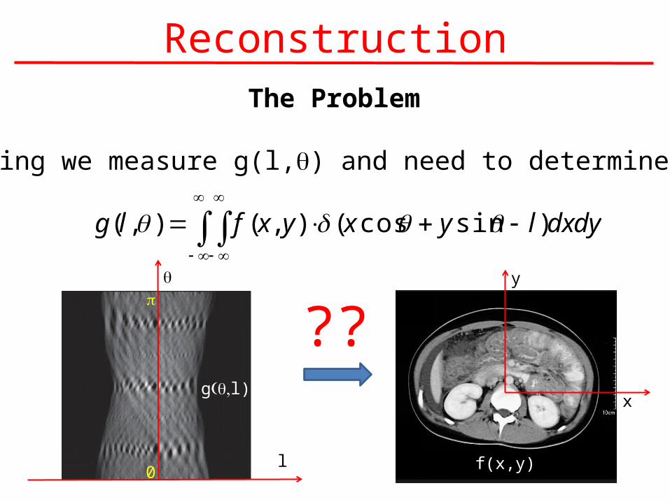
Reconstruction
dxdylyxyxflg )sincos(),(),(
The Problem
In imaging we measure g(l,q) and need to determine f(x,y)
q
l0
p
g( ,q l)x
y
f(x,y)
??
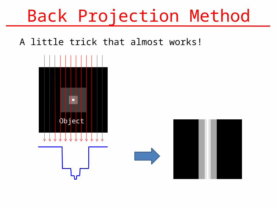
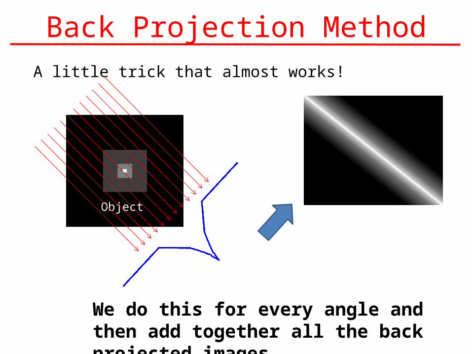
Back Projection MethodA little trick that almost works!
ObjectBack Projection
Back Projection MethodA little trick that almost works!
Object
Back Projection
We do this for every angle and then add together all the back projected images

Back Projection MethodStep #1: Generate a complete an image for each projection (e.g. for each angle q)
)),sin()cos((),( yxgyxb
Step #2: Add all the back projected images together
These are called back projected images
0
),(),( dyxbyxfb
Back Projection Method
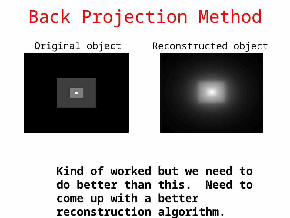
Kind of worked but we need to do better than this. Need to come up with a better reconstruction algorithm.
Reconstructed ImageOriginal object Reconstructed object
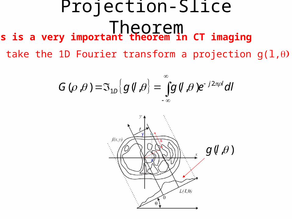
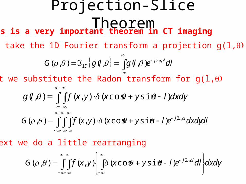
Projection-Slice TheoremThis is a very important theorem in CT imaging
First take the 1D Fourier transform a projection g(l, )q
dlelglgG ljD
21 ),(,(),(
),( lg
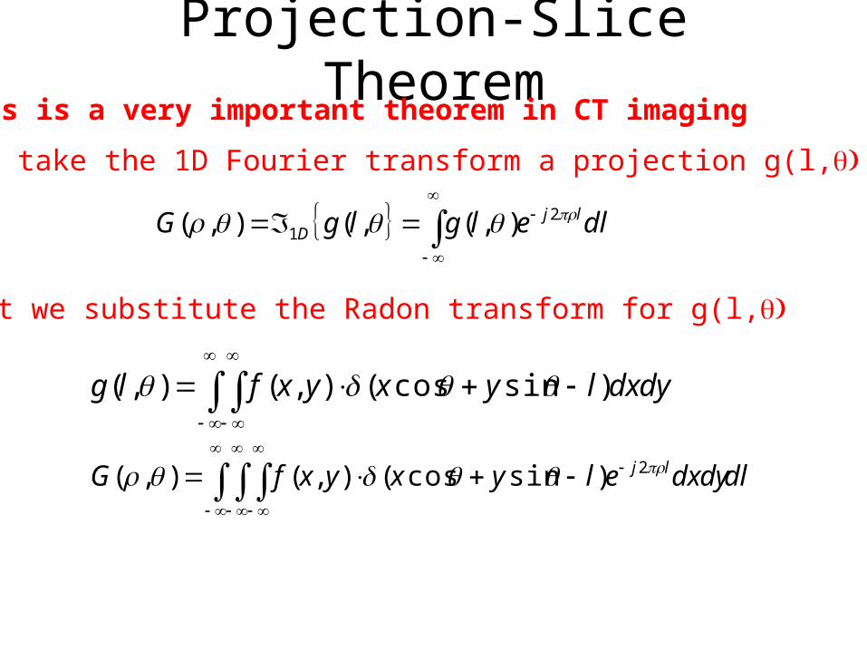
Projection-Slice TheoremThis is a very important theorem in CT imaging
First take the 1D Fourier transform a projection g(l, )q
dlelglgG ljD
21 ),(,(),(
Next we substitute the Radon transform for g(l, )q
dldxdyelyxyxfG lj 2)sincos(),(),(
dxdylyxyxflg )sincos(),(),(
Projection-Slice TheoremThis is a very important theorem in CT imaging
First take the 1D Fourier transform a projection g(l, )q
dlelglgG ljD
21 ),(,(),(
Next we substitute the Radon transform for g(l, )q
dldxdyelyxyxfG lj 2)sincos(),(),(
dxdylyxyxflg )sincos(),(),(
Next we do a little rearranging
dxdydlelyxyxfG lj 2)sincos(),(),(

Projection-Slice TheoremThis is a very important theorem in CT imagingNext we do a little rearranging
dxdydlelyxyxfG lj 2)sincos(),(),(
Applying the properties of the delta function
dxdyeyxfG
dxdyeyxfG
yxj
yxj
sincos2
sincos2
),(),(
),(),(
What does this look like?

Projection-Slice TheoremThis is a very important theorem in CT imaging
dxdyeyxfG
dxdyeyxfG
yxj
yxj
sincos2
sincos2
),(),(
),(),(
What does this look like?
This looks a lot like
dxdyeyxfvuF yvxuj 2),(),(
with )sin(),cos( vu
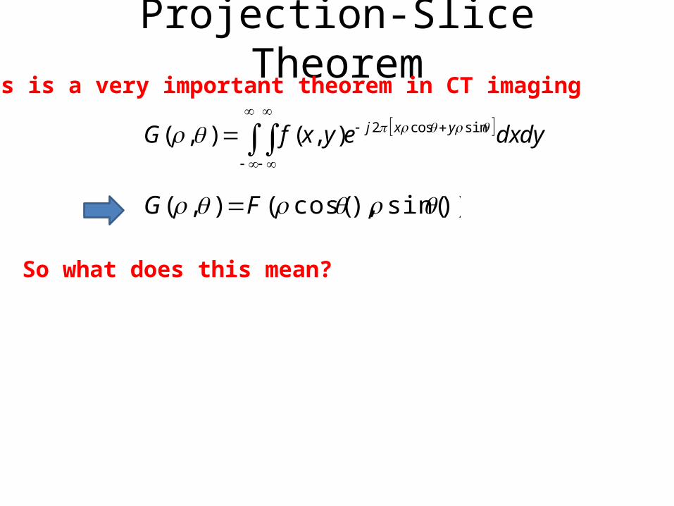
Projection-Slice TheoremThis is a very important theorem in CT imaging
))sin(),cos((),( FG
dxdyeyxfG yxj sincos2),(),(
So what does this mean?
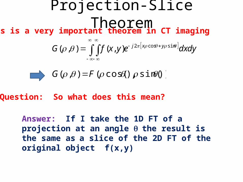
Projection-Slice TheoremThis is a very important theorem in CT imaging
))sin(),cos((),( FG
dxdyeyxfG yxj sincos2),(),(
Question: So what does this mean?
Answer: If I take the 1D FT of a projection at an angle q the result is the same asa slice of the 2D FT of the original object f(x,y)
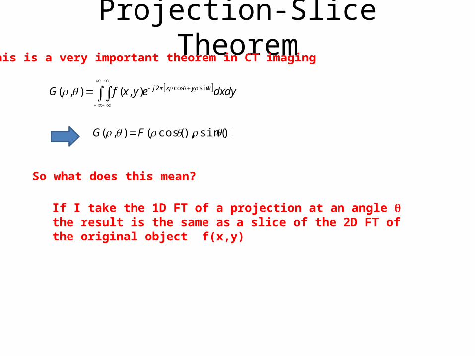
Projection-Slice TheoremThis is a very important theorem in CT imaging
))sin(),cos((),( FG
dxdyeyxfG yxj sincos2),(),(
So what does this mean?
If I take the 1D FT of a projection at an angle q the result is the same asa slice of the 2D FT of the original object f(x,y)
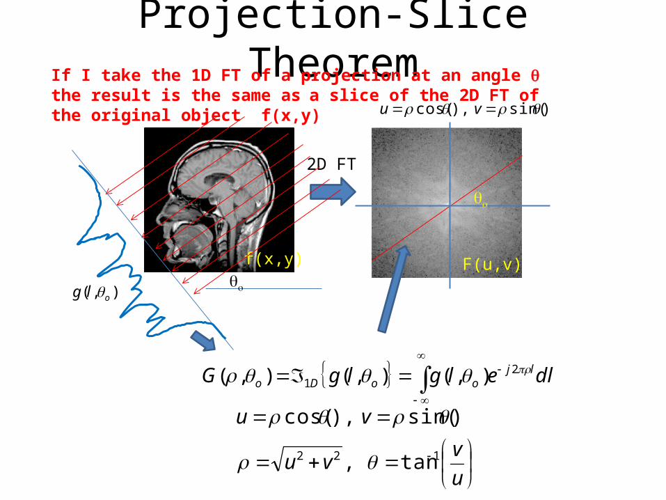
Projection-Slice TheoremIf I take the 1D FT of a projection at an angle q the result is the same asa slice of the 2D FT of the original object f(x,y)
f(x,y) F(u,v)
2D FT
dlelglgG ljooDo
21 ),(),(),(
),( olg qo
qo
)sin(),cos( vu
u
vvu
vu
122 tan,
)sin(),cos(
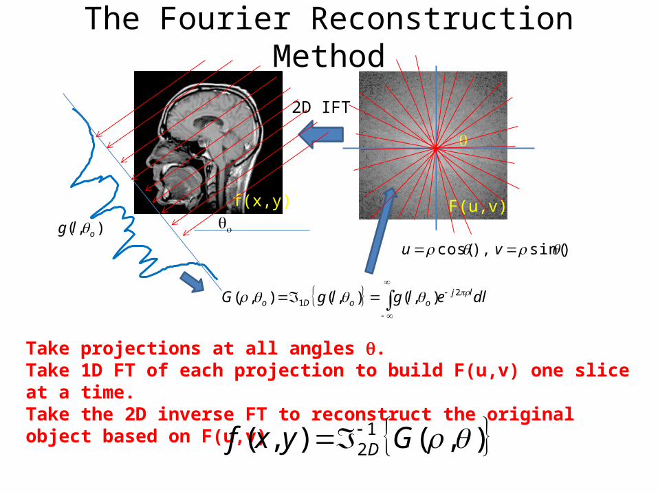
The Fourier Reconstruction Method
Take projections at all angles q.Take 1D FT of each projection to build F(u,v) one slice at a time.Take the 2D inverse FT to reconstruct the original object based on F(u,v)
f(x,y) F(u,v)
2D IFT
dlelglgG ljooDo
21 ),(),(),(
),( olg qo
q
),(),( 12 Gyxf D
)sin(),cos( vu
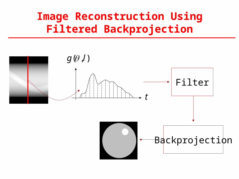
Image Reconstruction Using Filtered Backprojection
t
),( lg
Filter
Backprojection
Filtered Back Projection
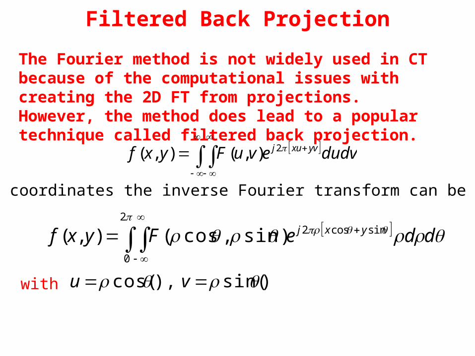
The Fourier method is not widely used in CT because of the computational issues with creating the 2D FT from projections. However, the method does lead to a popular technique called filtered back projection.
2
0
sincos2)sin,cos(),( ddeFyxf yxj
In polar coordinates the inverse Fourier transform can be written as
dudvevuFyxf yvxuj 2),(),(
with )sin(),cos( vu

Filtered Back Projection
The Fourier method is not widely used in CT because of the computational issues with creating the 2D FT from projections. However, the method does lead to a popular technique called filtered back projection.
2
0
sincos2)sin,cos(),( ddeFyxf yxj
In polar coordinates the inverse Fourier transform can be written as
with )sin(),cos( vu
From the projection theorem ))sin(),cos((),( FG
2
0
sincos2),(),( ddeGyxf yxjWe can write this as
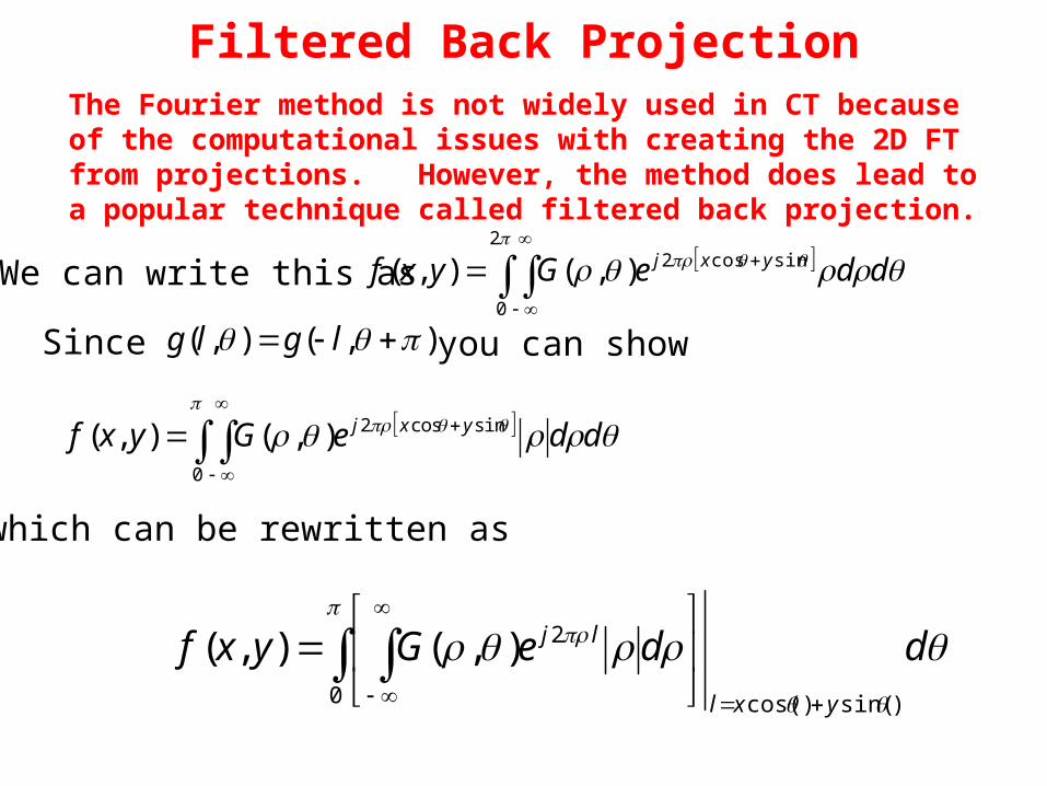
Filtered Back ProjectionThe Fourier method is not widely used in CT because of the computational issues with creating the 2D FT from projections. However, the method does lead to a popular technique called filtered back projection.
2
0
sincos2),(),( ddeGyxf yxjWe can write this as
Since ),(),( lglg you can show
0
sincos2),(),( ddeGyxf yxj
which can be rewritten as
0 )sin()cos(
2),(),( ddeGyxfyxl
lj

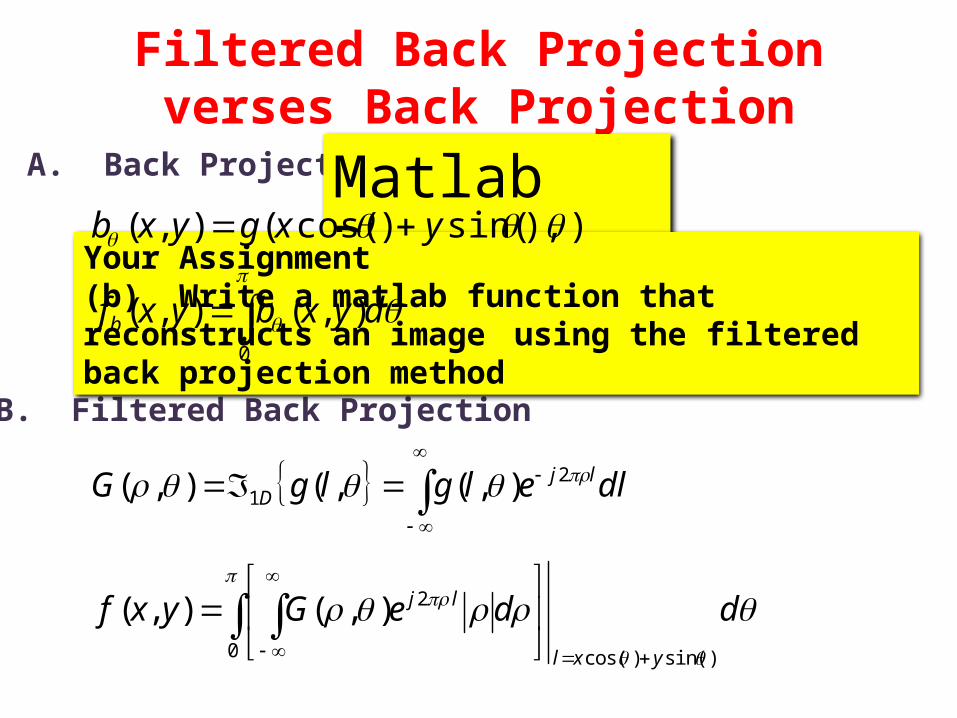
Filtered Back Projectionverses Back Projection
0 )sin()cos(
2),(),( ddeGyxfyxl
lj
)),sin()cos((),( yxgyxb
0
),(),( dyxbyxfb
A. Back Projection
B. Filtered Back Projection
dlelglgG ljD
21 ),(,(),(
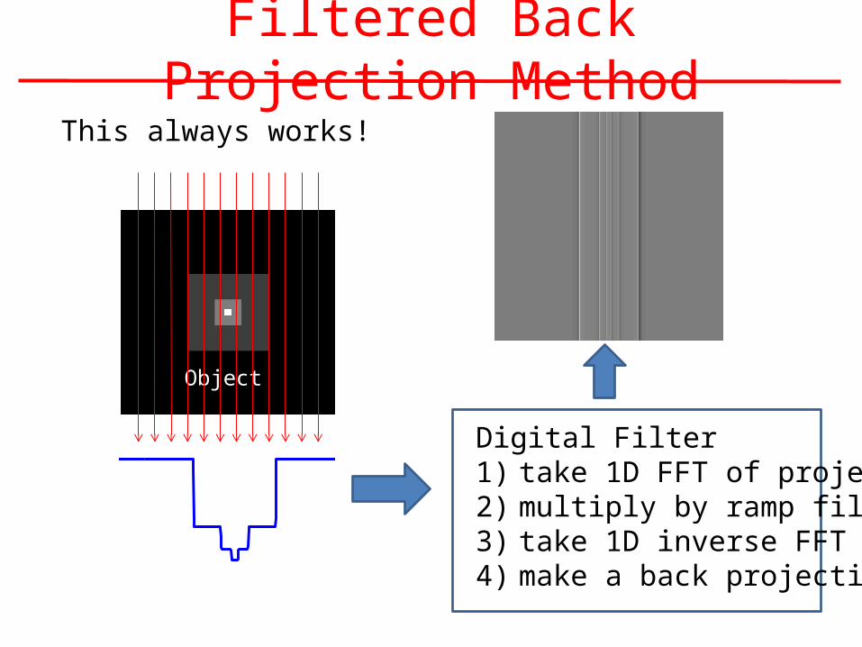
Filtered Back Projection MethodThis always works!
Object
Digital Filter1) take 1D FFT of projection2) multiply by ramp filter3) take 1D inverse FFT4) make a back projection
Filtered Back Projection

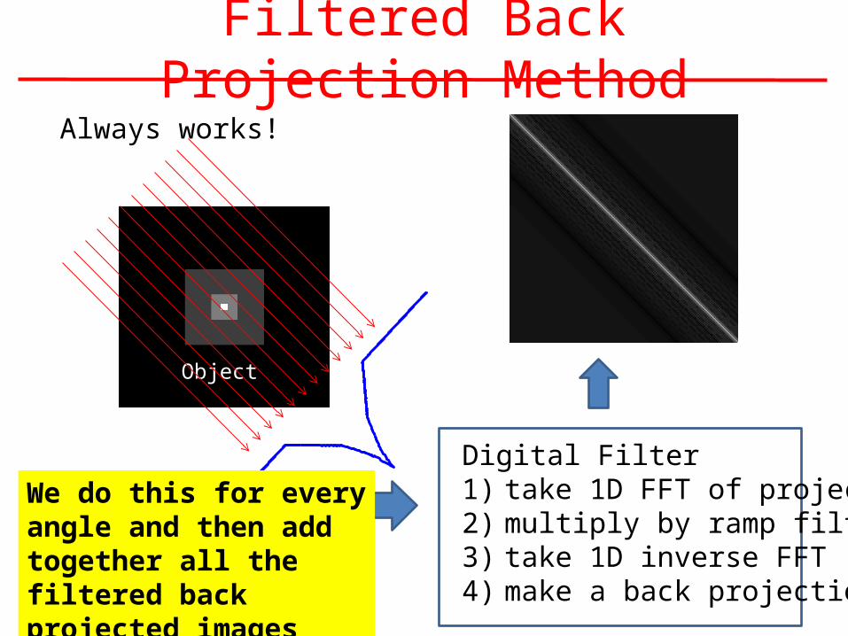
Filtered Back Projection MethodAlways works!
Object
Digital Filter1) take 1D FFT of projection2) multiply by ramp filter3) take 1D inverse FFT4) make a back projection
Filtered Back Projection
Filtered Back Projection MethodAlways works!
Object
Digital Filter1) take 1D FFT of projection2) multiply by ramp filter3) take 1D inverse FFT4) make a back projection
Filtered Back Projection
We do this for every angle and then add together all the filtered back projected images
Filtered Back Projectionverses Back Projection
0 )sin()cos(
2),(),( ddeGyxfyxl
lj
)),sin()cos((),( yxgyxb
0
),(),( dyxbyxfb
A. Back Projection
B. Filtered Back Projection
dlelglgG ljD
21 ),(,(),(
Matlab DemoYour Assignment(b) Write a matlab function that reconstructs an image
using the filtered back projection method
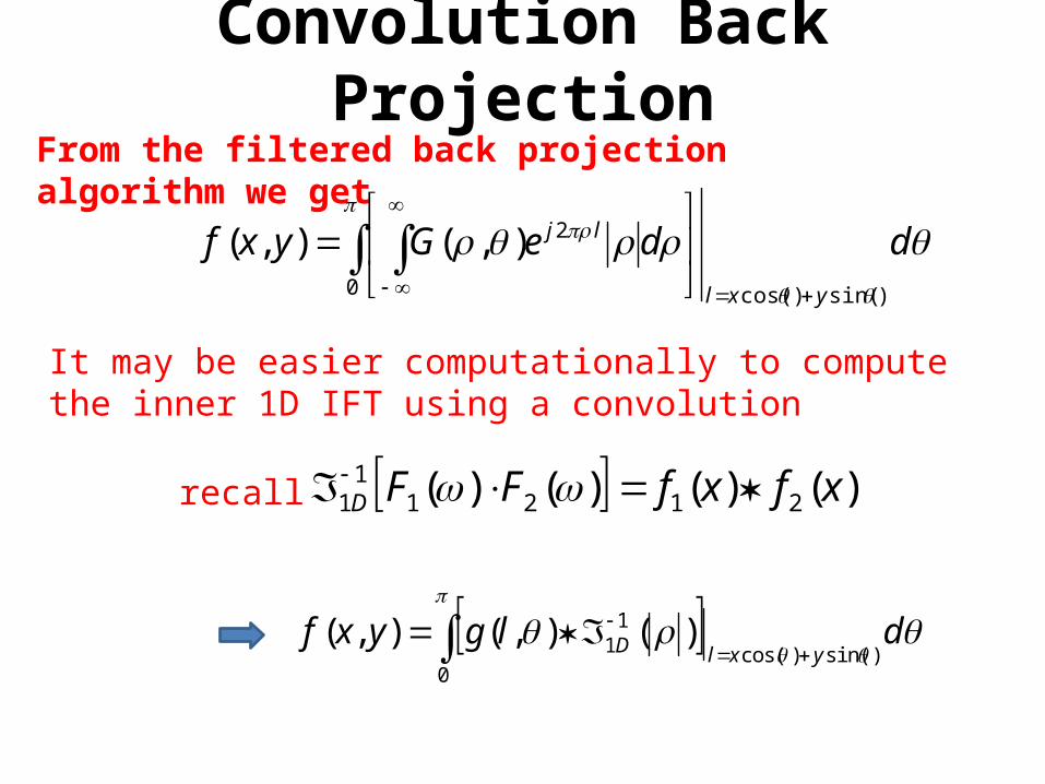
Convolution Back Projection
It may be easier computationally to compute the inner 1D IFT using a convolution
0 )sin()cos(
2),(),( ddeGyxfyxl
lj
From the filtered back projection algorithm we get
)()()()( 212111 xfxfFFD recall
0)sin()cos(
11 )(),(),( dlgyxf
yxlD

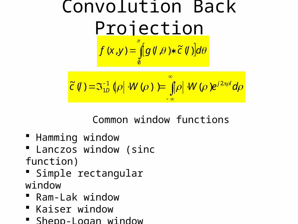
Convolution Back Projection
0)sin()cos(
11 )(),(),( dlgyxf
yxlD
Let
0)sin()cos(
11
)(),(),(
)()(
dlclgyxf
lc
yxl
D

Convolution Back Projection
The problem is delc ljD
211 )()(
does not exist
0)sin()cos(
11
)(),(),(
)()(
dlclgyxf
lc
yxl
D

Convolution Back Projection
The problem is delc ljD
211 )()(
does not exist
0)sin()cos(
11
)(),(),(
)()(
dlclgyxf
lc
yxl
D
The solution deWWlc ljD
211 )())(()(~
where )(W is called a weighting function
0
)(~),(),( dlclgyxf
deWWlc ljD
211 )())(()(~
Convolution Back Projection
Common window functions
Hamming window Lanczos window (sinc function) Simple rectangular window Ram-Lak window Kaiser window Shepp-Logan window
0
)(~),(),( dlclgyxf
deWWlc ljD
211 )())(()(~
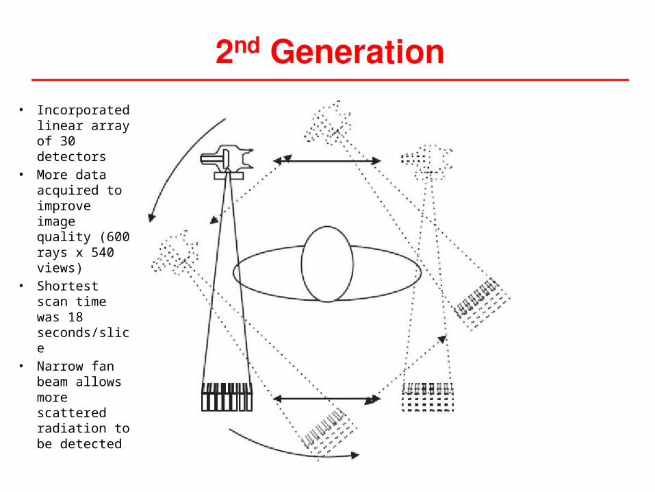
• Incorporated linear array of 30 detectors
• More data acquired to improve image quality (600 rays x 540 views)
• Shortest scan time was 18 seconds/slice
• Narrow fan beam allows more scattered radiation to be detected
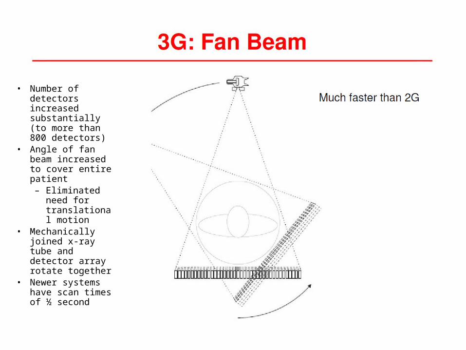
• Number of detectors increased substantially (to more than 800 detectors)
• Angle of fan beam increased to cover entire patient– Eliminated
need for translational motion
• Mechanically joined x-ray tube and detector array rotate together
• Newer systems have scan times of ½ second
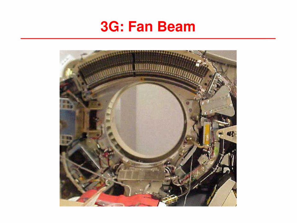

2G3G
Ring artifacts
• The rotate/rotate geometry of 3rd generation scanners leads to a situation in which each detector is responsible for the data corresponding to a ring in the image
• Drift in the signal levels of the detectors over time affects the t values that are backprojected to produce the CT image, causing ring artifacts

Ring artifacts
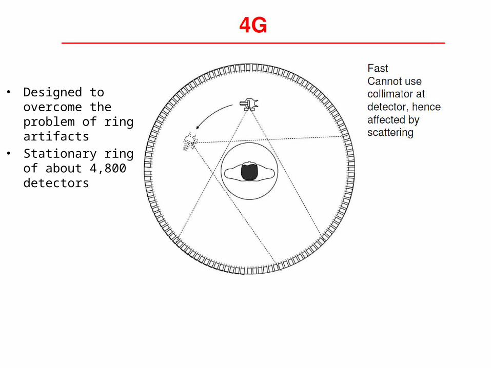
• Designed to overcome the problem of ring artifacts
• Stationary ring of about 4,800 detectors
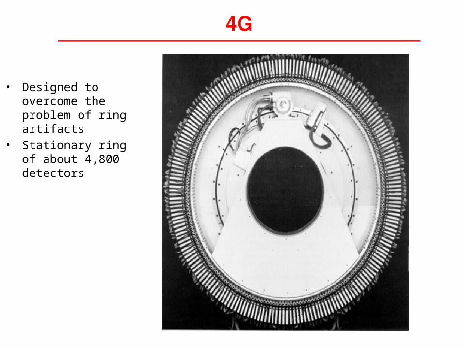
• Designed to overcome the problem of ring artifacts
• Stationary ring of about 4,800 detectors

• Developed specifically for cardiac tomographic imaging
• No conventional x-ray tube; large arc of tungsten encircles patient and lies directly opposite to the detector ring
• Electron beam steered around the patient to strike the annular tungsten target
• Capable of 50-msec scan times; can produce fast-frame-rate CT movies of the beating heart
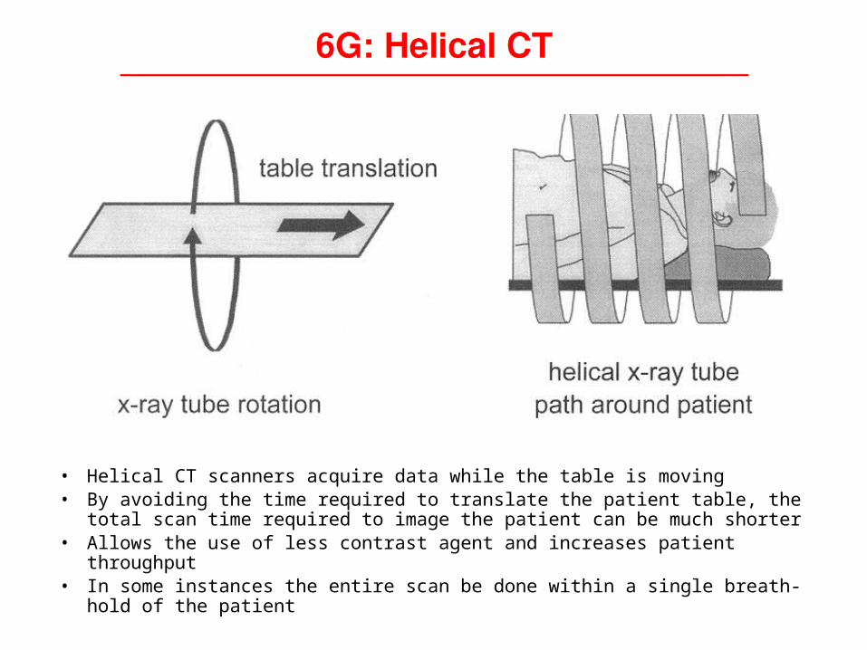
• Helical CT scanners acquire data while the table is moving• By avoiding the time required to translate the patient table, the total scan time
required to image the patient can be much shorter• Allows the use of less contrast agent and increases patient throughput• In some instances the entire scan be done within a single breath-hold of the
patient
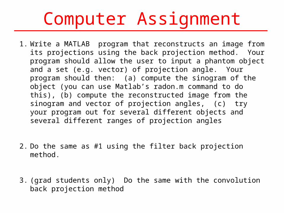
Computer Assignment1. Write a MATLAB program that reconstructs an image from its projections using
the back projection method. Your program should allow the user to input a phantom object and a set (e.g. vector) of projection angle. Your program should then: (a) compute the sinogram of the object (you can use Matlab’s radon.m command to do this), (b) compute the reconstructed image from the sinogram and vector of projection angles, (c) try your program out for several different objects and several different ranges of projection angles
2. Do the same as #1 using the filter back projection method.
3. (grad students only) Do the same with the convolution back projection method