Embed Size (px)
Citation preview


2
ÍndiceIndex
This catalogue covers the Roquet range of industrial directionalvalves and associated stacking valves and sub-plates.
The mounting dimensions of this range of valves conform to thefollowing standards: CETOP RP121H, DIN-24340 and ISO-4401.
The following sizes are produced: NG6 (CETOP 3), NG10 (CETOP5), NG16 (CETOP 7), NG25 (CETOP 8), NG32 (CETOP 10) givingnominal flow rates of 80 to 700 lpm at pressures up to 350 bar.Various control options are offered, depending on size: hand lever,solenoid, roller, hydraulic pilot etc. Please consult our proportionalvalve catalogue for proportional options.
A wide range of stacking valves (pressure control, flow control,check valves etc.) are available for the NG6 and NG10 valves(CETOP 3 & 5), as well as subplates with built-in relief valves.Appropriate use of these stacking valves can dramatically reducethe amount of pipe-work in a system.
Hydraulic damping of spool movement (to reduce system shockswith solenoid operated valves) can be provided for all sizes exceptNG6 (CETOP 3).
Hydraulic symbols used in this catalogue conform to ISO-1219.
Este catálogo cubre la gama de electroválvulas Roquet, junto consus elementos modulares y sus placas bases correspondientes.
Las dimensiones de conexión, están según normas ISO-4401,DIN-24340 y CETOP RP121H, con lo cual se obtiene una perfectaintercambiabilidad con la mayoria de fabricantes de oleo-hidráulica.
Poseen la particularidad de poderse montar en bloques compactos(TN-6 y TN-10) eliminando así tuberías y racores y con posibilidad deconseguir un circuito completo.
Exsiste una gran variedad de placas base y tapas superiores (TN-6y TN-10) para montar los elementos de forma separada eindependiente.
Podemos ofrecer la amortiguación de movimientos de la correderaen todos los elementos distribuidores, menos en el tamaño TN-6.
También disponemos de un cátalogo de hidráulica proporcional paraaccionamientos en los cuales se necesite una progresión o recesiónde movimiento.
Símbolos según norma ISO-1219
TN-6 (CETOP 3)
Electroválvulas ....................................................................... 3
Reguladores de presión ....................................................... 7
Placas base con limitadora ..................................................... 19
Bloques hidráulicos (CETOP 3) ............................................... 21
Válvulas de retención ............................................................. 23
Regulacón de caudal .............................................................. 26
Distribuidores acc. manual o mecánico .................................. 35
Placa base............................................................................... 44
TN-10 (CETOP 5)
Electroválvulas......................................................................... 46
Regulación de presión ............................................................ 50
Placas base con limitadora ..................................................... 59
Placas base multiples ............................................................. 61
Válvula de retención ............................................................... 63
Regulación de caudal .............................................................. 69
Placas base ............................................................................ 74
TN-16 - 25 - 32 (CETOP 7-8-10)
Electroválvulas......................................................................... 75
Distribuidores pilotaje hidráulico ............................................. 80
Distribuidores de mando manual ............................................. 80
Válvulas de frenado para electroválvulas ............................. 85
Válvulas de retención pilotada TN-25 .................................... 86
Placas base ............................................................................ 87
NG-6 (CETOP 3)Solenoid operated valves........................................................ 3
Pressure control ..................................................................... 7
Sub-plates with relief valves................................................... 19
CETOP 3 special manifold blocks ........................................ 21
Check valves........................................................................... 23
Flow control............................................................................. 26
Manual / mechanical valves ................................................... 35
Sub-plates .............................................................................. 44
NG-10 (CETOP 5)Solenoid operated valves........................................................ 46
Pressure control ..................................................................... 50
Sub-plates with relief valves .................................................. 59
CETOP 5 manifold blocks ..................................................... 61
Check valves........................................................................... 63
Flow control ............................................................................ 69
Sub-plates............................................................................... 74
NG-16 - 25 - 32 (CETOP 7-8-10)Solenoid operated valves ....................................................... 75
Hydraulically piloted valves ................................................... 80
Manual valves ......................................................................... 80
Damping for solenoid valves ................................................. 85
Check valve NG-25 (CETOP 8) ............................................. 86
Sub-Plates .............................................................................. 87
Eléctroválvulas y elementos modularesSolenoid operated valves and modular componentsISO - 4401 DIN - 24340 CETOP RP121H

3
Electroválvulas TN-6Solenoid operated valves NG-6
CETOP 3
Grado de limpieza del aceiteRecommended fluid cleanliness
19/16 s/. ISO 4406 - RP70Ho mejor / or better
Gama de temperaturas del fluidoFluid temperature range
Gama de viscosidadesViscosity range
Peso 2 electroimanesWeight with 2 solenoids
Peso variante un electroimánWeight with one solenoid
12V - 24V
Unom ± 10 %
Datos técnicos hidráulicosHydraulic technical data
315 bar
Estàtica - Static 210 barDinàmica - Dynamic 80 bar
ISO 6743 TIPO HM, HV ó HGISO 3448 Cat. VG32, VG46
-20ºC... +80ºC
4 - 500 cSt
1,8 Kg
1,4 Kg
Datos técnicos eléctricosElectrical technical data
Consumo por electroimánConsumption per solenoid
Corriente continuaD.C 38W
Corriente alternaA.C
180 VA
65 VA
Gama de tensiones para C.C.D.C. Voltage range
Gama de tensiones para C.A.A.C. Voltage range
Factor de marchaOperating factor
Tolerancia de tensiónVoltage tolerance
Protección según DIN-40050Protection to DIN-40050
Frecuencia de conexiónSwitching frequency
Tiempos de respuestaResponse time
Conectado / Switch onDesconectado / Switch off
24V-48V-110V-220V (50Hz)115V-230V (60Hz)
Continua / D.C.=Max. 15000/hAlterna / A.C.=7200/h
ContinuaD.C.
20 - 60 ms50 - 70 ms
10 - 25 ms25 - 50 ms
AlternaA.C
Presión máxima de trabajoMax. working pressure
Presión nominal en retornoNominal pressure in return
Caudal nominal máx.Max. nominal flow rate
Fluido recomendadoFluid to be used
ED 100%
IP - 65
80 L/min Circuito abiertoOpen circuit
Circuito cerradoClosed circuit
*220-50R02C1D3P5 EV CODING SYSTEMNOMENCLATURA DEREFERENCIAS
Datos adicionalesAdditional data
Forma correderaSpool form
1 - 2 - 3 - 4 - 5 - 6 - 7 - 8 - 13 - 17 - 18
VíasWays
C
B
4
3
D
R
Continua / Direct
Alterna / Alternating
Tipo corrienteCurrent type
Tensión y frequenciaVoltage and frequency
CA (AC)
CC (DC)
24 V - 48 V - 110 V - 220V (50 Hz)115 V - 230 V (60 Hz)
12 V - 24 V
Posiciones y electroimanesPositions and solenoids
14 Dos posiciones extrema y central (A)Two positions end and neutral (A)
13 Dos posiciones central y extrema (B)Two positions neutral and one end (B)
12 Dos posiciones central y extrema (A)Two positions neutral and one end (A)
3 Tres posiciones dos electroimanesThree positions two solenoids
2 Dos posiciones dos electroimanesTwo positions two solenoids
1 Dos posiciones un electroimán(Solo formas 7-8 y 17-18)Two positions one solenoid(Forms 7-8 and 17-18 only)
29 Dos posiciones extremas conanclaje mecánicoTwo positions with detent

4
(1) Comunica / Connected. (2) Cerrado / closed.
*Tipo de corriente del electroimán.D para corriente continua, indicando a continuación la tensión deseada.R para corriente alterna, indicando a continuación la tensión y frequencia deseadas.
*Solenoid current type :D for D.C. current, indicating after it voltage required.R for A.C. current, indicating after it voltage and frequency required.
ReferenciaReference
Formade la
correderaSpoolform
SímboloSymbol Posición central
Central position
Solenoide Bconectado
Solenoid Bswitched on
5EVP3D1C02*
5EVP3D2C02*
5EVP3D3C02*
5EVP3D4C02*
5EVP3D5C02*
5EVP3D6C02*
5EVP3D13C02*
5EVP2D2C02*
5EVP29D2C02*
5EVP12D4C02*
5EVP1D7B02*
5EVP1D8C02*
5EVP1D17B02*
5EVP1D18C02*
7
8
17
18
Solenoid conectadoSolenoid switched on
Solenoid desconectadoSolenoid switched off
P (1) A B (1) R
P (1) B A (1) R
P (1) A B (2) R
P (1) B A (1) R
A y B (2) P (1) R
A, B, P y R (2)
A y B (1) R P (2)
A, B, P (1) R
A (1) R B y P (2)
A (2) B y P (1) R
A y B (1) P R (2)
A, B, P (1) R
P(1) A B y R (2)
P (1) A B (1) R
P (1) B A y R (2)
P (1) B A (1) R
P (1) B A y R (2)
P (1) B A (1) R
P (1) A B y R (2)
P (1) A B (1) R
3
4
2
6
13
2
2
4
5
1 P (1) B A (1) R
P (1) A B (1) R
P (1) B A (1) R
P (1) A B (1) R
Circulación de aceite / Connections
Solenoide Aconectado
Solenoid Aswitched on
A B
Variante con un electroimán para formas 17 y 18 y montaje 12 o 14Version with one solenoid (spools 17 and 18)
26
,6
6
Ø 12,5
5,5
Para formas 7, 8 y en montaje 13, el electroimán estará situado en el ladode la toma«B»For spools 7, 8 and assembly type 13 the solenoid will be placed at side ofoutlet «B»
212 C.A./ A.C.242 C.C./ D.C.
PG - 11Conexión eléctricaElectrical connection
41
1,3
5
Ø 8
85
75
49
24
46
= =PulsadorManual over-ride
28
40,5
27,8
19
10,3
20
32
,5
6,7
5
78
31
==
16
,3
P Entrada de presiónPressure inlet
A y B Tomas a cilindros o motoresOutlet to cylinders or motors
R RetornoReturn
155 C.A. / A.C.170 C.C. / D.C.
8
5
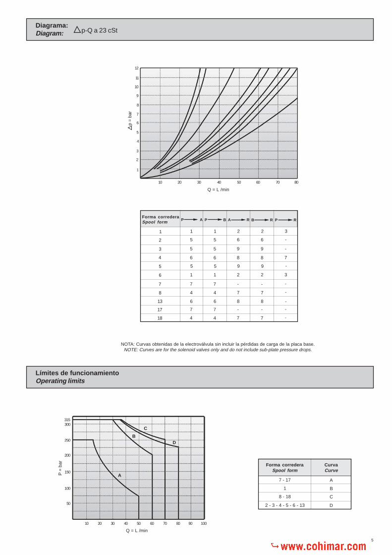
NOTA: Curvas obtenidas de la electroválvula sin incluir la pérdidas de carga de la placa base.NOTE: Curves are for the solenoid valves only and do not include sub-plate pressure drops.
Diagrama:Diagram: p-Q a 23 cSt
Límites de funcionamientoOperating limits
12
11
10
9
8
7
6
5
4
3
2
1
10 20 30 40 50 60 70 80
Q = L /min
p =
bar
P AForma correderaSpool form
1
2
3
4
5
6
17
18
B R P R
-
-
7
3
-
-
-
3
P A A R
1
5
5
6
1
7
4
5
1
5
5
6
1
7
4
5
6
9
8
2
-
7
9
2
6
9
8
2
-
7
9
2
P B
13 -6 6 8 8
7
8
-
-
7
4
7
4
-
7
-
7
P =
bar
300315
250
200
150
100
50
10 20 30 40 50 60 70 80 90 100
Q = L /min
C
DB
A
Forma correderaSpool form
CurvaCurve
7 - 17
1
8 - 18
2 - 3 - 4 - 5 - 6 - 13
A
B
C
D

6
AccionamientoPositioning device 2
AccionamientoPositioning device 3
AccionamientoPositioning device 14
AccionamientoPositioning device 13
AccionamientoPositioning device 12
AccionamientoPositioning device
1AccionamientoPositioning device
29
Platillo centraje para Forma 1
Platillo centraje
Conj. cuerpo y corredera
Juntas tóricas
Muelle para C.C.
Muelle para C.A.
Junta tórica
Conj. electroimán completo
Placa base individualSub-plate
Tormillos para fijaciónFixing bolts
RFE. 321001-321002-321031-321032Según necesidadesAs per requirements
4TornillosBolts DIN - 912 M5x50
Par de aprieteTorque 7-9 Nm.
Solenoid connector
Solenoid connector
Spring stop ring
Cover
O´ring
O´ring
Solenoid Core
Coil
Spool guide for Form 1
Spool guide
Body and spool
O´ring
Spring for D.C.
Spring for A.C.
O´ring
Solenoid complete
DenominaciónDescription
3
4
2
6
7
8
5
1
Núm.No.
Cant.Qty.
11
12
10
14
15
16
13
9
DenominaciónDescription
Núm.No.
Cant.Qty.
1
1
1 - 2
1
2
1 - 2
1 - 2
1 - 2
2
2
1
4
2
2
1 - 2
1
Enchufe electroimán lado «A»
Enchufe electroimán lado «B»
Aguja accionamiento
Placa referencias
Junta tórica
Junta tórica
Núcleo electroimán
Bobina
Accesorios Requieren pedido por separadoAccessories That need separate orders
Ø 17,1X1,8
Ø 9,25X1,77
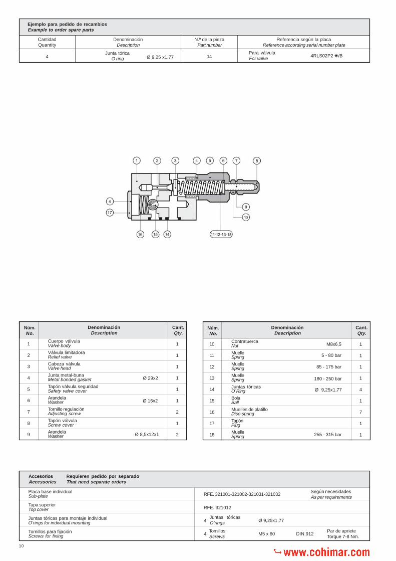
Ejemplo para pedido de recambiosExample to order spare parts
CantidadQuantity
DenominaciónDescription
N.º de la piezaPart number
Referencia según la placaReference according serial number plate
2Junta tórica
O ring 5Para válvulaFor valve 5EVP3D2C02R220-50
Nut
Spool stop
Spring shim
Plug
Spring
Detent
Ball
Spool stop (detent)
19
20
18
22
23
24
21
17
DenominaciónDescription
Núm.No.
Cant.Qty.
1 - 2
2
1
1
1
1
4
1
Tuerca
Piezas pos. extremas
Suplemento muelle
Tapón corredera
Resorte circular
Pieza enclaje
Bolas
Tope anclajes
Ø 2
7
260
240
220
200
180
160
140
120
100
80
60
40
20
Serie / Type 4RL
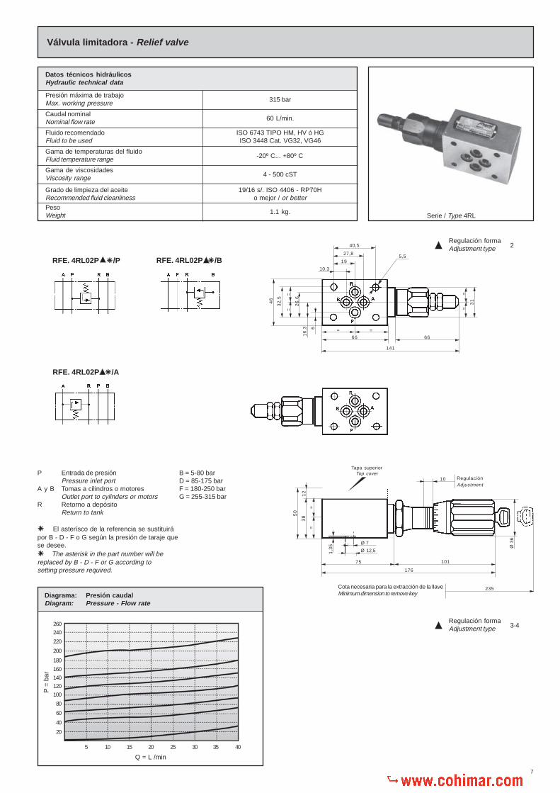
Válvula limitadora - Relief valveP
= b
ar
Q = L /min
5 10 15 20 25 30 35 40
Diagrama: Presión caudalDiagram: Pressure - Flow rate
Grado de limpieza del aceiteRecommended fluid cleanliness
19/16 s/. ISO 4406 - RP70Ho mejor / or better
Datos técnicos hidráulicosHydraulic technical data
Presión máxima de trabajoMax. working pressure
Caudal nominalNominal flow rate
Fluido recomendadoFluid to be used
Gama de temperaturas del fluidoFluid temperature range
Gama de viscosidadesViscosity range
PesoWeight
315 bar
60 L/min.
ISO 6743 TIPO HM, HV ó HGISO 3448 Cat. VG32, VG46
-20º C... +80º C
4 - 500 cST
1.1 kg.
RFE. 4RL02P �/A
RFE. 4RL02P �/B
66
=
40,5
5,527,8
19
10,3
141
66
=
31
==
46
32
,5
==
16
,3 6
26
,6
Regulación formaAdjustment type 2
10
235
Ø 3
6
176
75 101
RegulaciónAdjustment
Ø 12,51,3
5 Ø 7
50
38
==
Tapa superiorTop cover
Cota necesaria para la extracción de la llaveMinimum dimension to remove key
12
Regulación formaAdjustment type 3-4
P Entrada de presiónPressure inlet port
A y B Tomas a cilindros o motoresOutlet port to cylinders or motors
R Retorno a depósitoReturn to tank
�� El asterísco de la referencia se sustituirápor B - D - F o G según la presión de taraje quese desee.��The asterisk in the part number will bereplaced by B - D - F or G according tosetting pressure required.
B = 5-80 barD = 85-175 barF = 180-250 barG = 255-315 bar
RFE. 4RL02P �/P

8
RFE. 321001-321002-321031-321032
RFE. 321012
Valve body
Relief valve
Valve head
Metal bonded gasket
Cover
Lock nut
Copper gaskets
Blind nut
Adjusting screw
Washer
Spring
Spring
Spring
Balls
Knob fixing pin
Guía volante
Cerradura
Pasador elástico
Muelle
Tapón tope bolas
Volante
Volante
Sumplemento volante
Pasador elástico
Junta tórica
Junta tórica
Adaptador volante
Tornillo regulación
Juntas tóricas
Muelle
Cuerpo válvula
Válvula limitadora
Cabeza válvula
Junta metal-buna
Tapón válvula
Contratuerca
Juntas cobre
Tuerca sombrerete
Tornillo regulación
Arandela tope muelle
Muelle
Muelle
Muelle
Bolas
Guía volante
1
2
3
4
5
6
7
8
9
10
11
12
13
14
15
DenominaciónDescription
Núm.No.
Cant.Qty.
1
1
1
1
1
1
2
1
1
1
1
1
1
30
1
5-80 bar
85-175 bar
180-250 bar
16
17
18
19
20
21
22
23
24
25
26
27
28
29
30
DenominaciónDescription
Núm.No.
Cant.Qty.
1
1
2
1
1
1
1
1
1
1
1
1
1
4
1
DIN-1481 Ø 3x18
Ø 16,2x2,7
Ø 10,55x2,7
DIN-1481 Ø 2 X 20
Ø 9,25X1,77
255-315 bar
Knob guide
Locking system
Elastic pin
Spring
Plug
Knob
Knob
Knob cover
Elastic pin
O’ring
O’ring
Knob adaptor
Adjusting screw
O’ring
Spring
Ejemplo para pedido de recambiosExample to order spare parts
CantidadQuantity
DenominaciónDescription
N.º de la piezaPart number
Referencia según la placaReference according serial number plate
1Junta tóricaO ring 26
Para válvulaFor valve 4RL02P2DØ 8,9 x 1,9
Según necesidadesAs per requirements
Accesorios Requieren pedido por separadoAccessories That need separate orders
4
4
Juntas tóricasO’rings
TornillosScrews
Ø 9,25x1,77
M5 x 55 DIN.912Par de aprieteTorque 7-8 Nm.
Placa base individual
Tapa superior
Juntas tóricas para montaje individual
Tornillos para fijación
Sub-plate
Top cover
O’rings for individual mounting
Screws for fixing

9
Válvula de sobrepresión simple - Simple relief valve
Serie / Type 4RLS
260
240
220
200
180
160
140
120
100
80
60
40
20
P =
bar
Q = L /min
5 10 15 20 25 30 35 40
Diagrama: Presión caudalDiagram: Pressure - Flow rate
RFE. 4RLS02P2�/B
P Entrada de presiónPressure inlet port
A y B Tomas a cilindros o motoresOutlet ports to cylinders or motors
R Retorno a depósitoReturn to tank
B = 5-80 barD = 85-175 barF = 180-250 barG = 255-315 bar
�El asterísco de la referencia se sustituirápor B - D - F o G según la presión de taraje quese desee.�The asterisk in the part number will bereplaced by B - D - F or G according tosetting pressure required.
Datos técnicos hidráulicosHydraulic technical data
Presión máxima de trabajoMax. working pressure
Caudal nominalNominal flow rate
Fluido recomendadoFluid to be used
Gama de temperaturas del fluidoFluid temperature range
Gama de viscosidadesViscosity range
Grado de limpieza del aceiteRecommended fluid cleanliness
PesoWeight
315 bar
40 L/min.
ISO 6743 TIPO HM, HV ó HGISO 3448 Cat. VG32, VG46
-20º C... +80º C
4 - 500 cST
19/16 s/. ISO 4406 - RP70Ho mejor / or better
1,150 kg.
=
32
,5
=
=
66
138
66
= =
6
16
,3 6
46
26
,6
40,5
27,8
19
10,3
31
=
5,5
46
14
,5
58
14
,5
12
Tapa superiorTop cover
Regulación tomaOutlet adjustment B
Regulación tomaOutlet adjustment A
1,3
5
Ø 12,5
Ø 8
1,3
5
Ø 12,5
Ø 8
RFE. 4RLS02P2�/A
10
RFE. 321001-321002-321031-321032
RFE. 321012
Ø 9,25 x1,77
Ejemplo para pedido de recambiosExample to order spare parts
CantidadQuantity
DenominaciónDescription
N.º de la piezaPart number
Referencia según la placaReference according serial number plate
4Junta tórica
O ring 14Para válvulaFor valve 4RLS02P2�/B
10
11
12
13
14
15
16
17
18
Cuerpo válvula
Válvula limitadora
Cabeza válvula
Junta metal-buna
Tapón válvula seguridad
Arandela
Tornillo regulación
Tapón válvula
Arandela
Valve body
Relief valve
Valve head
Metal bonded gasket
Safety valve cover
Washer
Adjusting screw
Screw cover
Washer
1
2
3
4
5
6
7
8
9
DenominaciónDescription
Núm.No.
Cant.Qty.
1
1
1
1
1
1
2
1
2
Ø 29x2
Ø 15x2
Ø 8,5x12x1
Contratuerca
Muelle
Muelle
Muelle
Juntas tóricas
Bola
Muelles de platillo
Tapón
Muelle
Nut
Spring
Spring
Spring
O´Ring
Ball
Disc-spring
Plug
Spring
DenominaciónDescription
Núm.No.
Cant.Qty.
1
1
1
1
4
1
7
1
1
5 - 80 bar
Ø 9,25x1,77
M8x6,5
85 - 175 bar
180 - 250 bar
255 - 315 bar
Según necesidadesAs per requirements
Accesorios Requieren pedido por separadoAccessories That need separate orders
4
4
Juntas tóricasO’rings
TornillosScrews
Ø 9,25x1,77
M5 x 60 DIN.912Par de aprieteTorque 7-8 Nm.
Placa base individual
Tapa superior
Juntas tóricas para montaje individual
Tornillos para fijación
Sub-plate
Top cover
O’rings for individual mounting
Screws for fixing

11
260
240
220
200
180
160
140
120
100
80
60
40
20
P =
bar
Q = L /min
5 10 15 20 25 30 35 40
Diagrama: Presión caudalDiagram: Pressure - Flow rate
Válvula de sobrepresión doble - Double relief valve
Serie / Type 4RLD
Datos técnicos hidráulicosHydraulic technical data
Presión máxima de trabajoMax. working pressure
Caudal nominalNominal flow rate
Fluido recomendadoFluid to be used
Gama de temperaturas del fluidoFluid temperature range
Gama de viscosidadesViscosity range
Grado de limpieza del aceiteRecommended fluid cleanliness
PesoWeight
315 bar
40 L/min.
ISO 6743 TIPO HM, HV ó HGISO 3448 Cat. VG32, VG46
-20º C... +80º C
4 - 500 cST
19/16 s/. ISO 4406 - RP70Ho mejor / or better
1,250 kg.
RFE. 4RLD02P2� /�
Ø 8
6666
198
46
15
16
,3
46
32
,5
6
26
,6
==
58
15
12
40,5
27,8
19
10,3
= =66
31
==
Ø 12,51,3
5
5,5
Tapa superiorTop cover
P Entrada de presiónPressure inlet port
A y B Tomas a cilindros o motoresOutlet ports to cylinders or motors
R Retorno a depósitoReturn to tank
B = 5-80 barD = 85-175 barF = 180-250 barG = 255-315 bar
�El asterísco de la referencia se sustituirápor B - D - F o G según la presión de taraje quese desee.�The asterisk in the part number will bereplaced by B - D - F or G according tosetting pressure required.

12
RFE. 321001-321002-321031-321032
RFE. 321012
Según necesidadesAs per requirements
Tapón válvula
Tornillo regulador
Arandela
Tapón válvula seguridad
Junta metal-buna
Arandela
Contratuerca
Muelle
Screw cover
Adjusting screw
Washer
Relief valve cover
Metal bonded gasket
Washer
Nut
Spring
1
2
3
4
5
6
7
8
DenominaciónDescription
Núm.No.
Cant.Qty.
2
2
2
2
2
4
2
2
Ø 29x2
M8x6,5
Ø 15x2
9
10
11
12
13
14
15
DenominaciónDescription
Núm.No.
Cant.Qty.
2
2
2
2
4
1
1
180-250 bar
Ø 9,25x1,77
85-175 barMuelle
Muelle
Cabeza válvula
Válvula limitadora
Juntas tóricas
Cuerpo válvula
Muelle
Spring
Spring
Valve head
Relief valve
O´Rings
Valve body
Spring 255 - 315 bar
5-80 bar
Cuerpo válvulaValve body
Ejemplo para pedido de recambiosExample to order spare parts
CantidadQuantity
DenominaciónDescription
N.º de la piezaPart number
Referencia según la placaReference according serial number plate
1 14Para válvulaFor valve 4RLD02P2B/B
Accesorios Requieren pedido por separadoAccessories That need separate orders
4
4
Juntas tóricasO’rings
TornillosScrews
Ø 9,25x1,77
M5 x 60 DIN.912Par de aprieteTorque 7-8 Nm.
Placa base individual
Tapa superior
Juntas tóricas para montaje individual
Tornillos para fijación
Sub-plate
Top cover
O’rings for individual mounting
Screws for fixing
13
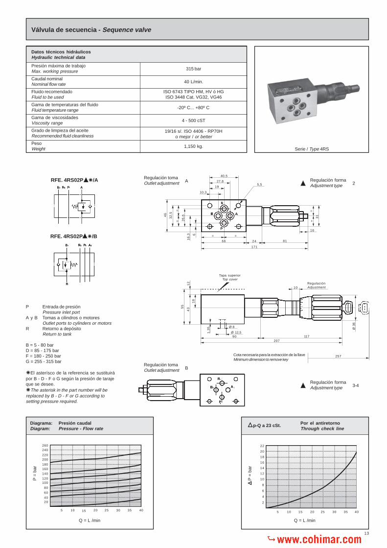
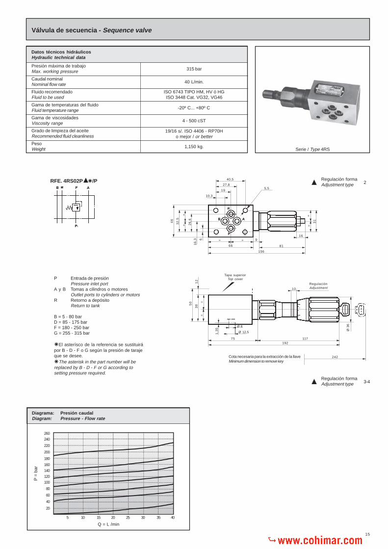
Válvula de secuencia - Sequence valve
Datos técnicos hidráulicosHydraulic technical data
Presión máxima de trabajoMax. working pressure
Caudal nominalNominal flow rate
Fluido recomendadoFluid to be used
Gama de temperaturas del fluidoFluid temperature range
Gama de viscosidadesViscosity range
Grado de limpieza del aceiteRecommended fluid cleanliness
PesoWeight
315 bar
40 L/min.
ISO 6743 TIPO HM, HV ó HGISO 3448 Cat. VG32, VG46
-20º C... +80º C
4 - 500 cST
19/16 s/. ISO 4406 - RP70Ho mejor / or better
1,150 kg.Serie / Type 4RS
Q = L /min
Por el antiretornoThrough check line
5 10 15 20 25 30 35 40
22
20
18
16
14
12
10
8
6
4
2
p-Q a 23 cSt.
260240
220200
180160140
120100
80
60
4020
5 10 15 20 25 30 35 40
Q = L /min
Diagrama: Presión caudalDiagram: Pressure - Flow rate
P =
bar
P =
bar
RegulaciónAdjustment
P Entrada de presiónPressure inlet port
A y B Tomas a cilindros o motoresOutlet ports to cylinders or motors
R Retorno a depósitoReturn to tank
B = 5 - 80 barD = 85 - 175 barF = 180 - 250 barG = 255 - 315 bar
�El asterísco de la referencia se sustituirápor B - D - F o G según la presión de tarajeque se desee.�The asterisk in the part number will bereplaced by B - D - F or G according tosetting pressure required.
RFE. 4RS02P �/A
RFE. 4RS02P �/B
117207
90Ø 12,51
,35 Ø 8
Regulación tomaOutlet adjustment
=
46
32
,5
=
16
,3 6
26
,6
10,3
27,8
19
40,5
5,5
8166
= =
171
24
31
==
16
55
43
18
12
10
Tapa superiorTop cover
257Ø
36
Cota necesaria para la extracción de la llaveMinimum dimension to remove key
B
Regulación formaAdjustment type 2
Regulación formaAdjustment type 3-4
Regulación tomaOutlet adjustment A

14
RFE. 321001-321002-321031-321032
RFE. 321012
Cuerpo válvula
Válvula limitadora
Asiento válvula
Cabeza válvula
Junta antiextrusión
Junta tórica
Muelle
Muelle
Muelle
Contratuerca
Tornillo regulación
Arandela
Valve body
Relief valve
Valve heat
Valve head
Anti-extrusion gasket
O´ring
Spring
Spring
Spring
nut
Adjusting screw
Washer
DenominaciónDescription
3
4
2
6
7
8
9
10
11
12
5
1
Núm.No.
Cant.Qty.
1
1
1
1
1
1
1
1
1
1
1
1
DenominaciónDescription
15
16
14
18
19
20
21
22
23
24
17
13
Núm.No.
Cant.Qty.
1
1
1
1
1
1
1
1
4
1
30
1
DenominaciónDescription
27
28
26
30
31
32
33
34
35
36
29
25
Núm.No.
Cant.Qty.
1
2
1
1
1
1
1
1
1
1
1
1
Tapón válvula seguridad
Guía muelle
Junta
Guía émbolo
Embolo
Junta tórica
Junta cobre
Bola
Junta tórica
Adaptador volante
Bola
Guía volante
Safety valve cover
Spring guide
Gasket
Piston guide
Piston
O´ring
Cooper gasket
Ball
O´Ring
Knob adaptor
Ball
Knob fixing pin
Guía volante
Cerradura
Pasador
Muelle
Tapón tope bolas
Volante
Tornillo regulación
Junta tórica
Pasador elástico
Suplemento volante
Volante
Muelle
Knob guide
Loking system
Elastic pin
Spring
Plug
Knob
Adjusting screw
O´Ring
Elastic pin
Knob cover
Knob
Spring
Ø 3,1x1,6
Ø 5-80 bar
85 - 175 bar
180 - 250 bar
Ø 14x2
Ø 14x18x1
Ø 6,5
Ø 9,25x1,77
Ø 2x20
Ø 16,9x2,7
Ø 3x18
255 - 315 bar
Cuerpo válvulaValve body
Ejemplo para pedido de recambiosExample to order spare parts
CantidadQuantity
DenominaciónDescription
N.º de la piezaPart number
Referencia según la placaReference according serial number plate
1 1Para válvulaFor valve 4RS02P2B/A
Según necesidadesAs per requirements
Accesorios Requieren pedido por separadoAccessories That need separate orders
4
4
Juntas tóricasO’rings
TornillosScrews
Ø 17x2
M5x60 DIN.912Par de aprieteTorque 7-8 Nm.
Placa base individual
Tapa superior
Juntas tóricas para montaje individual
Tornillos para fijación
Sub-plate
Top cover
O’rings for individual mounting
Screws for fixing
15
Válvula de secuencia - Sequence valve
Datos técnicos hidráulicosHydraulic technical data
Presión máxima de trabajoMax. working pressure
Caudal nominalNominal flow rate
Fluido recomendadoFluid to be used
Gama de temperaturas del fluidoFluid temperature range
Gama de viscosidadesViscosity range
Grado de limpieza del aceiteRecommended fluid cleanliness
PesoWeight
315 bar
40 L/min.
ISO 6743 TIPO HM, HV ó HGISO 3448 Cat. VG32, VG46
-20º C... +80º C
4 - 500 cST
19/16 s/. ISO 4406 - RP70Ho mejor / or better
1,150 kg.Serie / Type 4RS
260
240
220
200
180
160
140
120
100
80
60
40
20
P =
bar
Q = L /min
5 10 15 20 25 30 35 40
Diagrama: Presión caudalDiagram: Pressure - Flow rate
P Entrada de presiónPressure inlet port
A y B Tomas a cilindros o motoresOutlet ports to cylinders or motors
R Retorno a depósitoReturn to tank
B = 5 - 80 barD = 85 - 175 barF = 180 - 250 barG = 255 - 315 bar
�El asterísco de la referencia se sustituirápor B - D - F o G según la presión de tarajeque se desee.�The asterisk in the part number will bereplaced by B - D - F or G according tosetting pressure required.
RFE. 4RS02P �/P
Cota necesaria para la extracción de la llaveMinimum dimension to remove key
40,5
27,8
195,5
10,31
21
6,3 9
16
11775
=
46
32
,5
=
6
26
,6
Tapa superiorTop cover
8166
156
= =
10
Ø 3
6
RegulaciónAdjustment
242
Ø 12,51,3
5
Ø 8
192
50
38
==
==
31
Regulación formaAdjustment type 2
Regulación formaAdjustment type 3-4

16
RFE. 321001-321002-321031-321032
RFE. 321012
1
1
1
1
1
1
1
1
1
1
1
1
1
1
1
1
1
1
1
1
4
1
Suplemento volante
Volante
Bolas
Guía volante
Guía volante
Cerradura
Pasador elástico
Muelle
Tapón tope bolas
Volante
Muelle
1
1
30
1
1
1
1
1
1
1
1
Knob cover
Knob
Ball
Knob fixing pin
Knob guide
Loking system
Elastic pin
Spring
Plug
Knob
Spring
Cuerpo válvula
Válvula limitadora
Cabeza válvula
Junta antiextrusión
Junta tórica
Muelle
Muelle
Muelle
Contratuerca
Tornillo regulación
Arandela
Valve body
Relief valve
Valve head
Anti-extrusion gasket
O´ring
Spring
Spring
Spring
Nut
Adjusting screw
Washer
DenominaciónDescription
3
4
2
6
7
8
9
10
11
5
1
Núm.No.
Cant.Qty.
Tapón válvula seguridad
Guía muelle
Junta
Guía émbolo
Embolo
Junta tórica
Adaptador volante
Tornillo regulación
Junta tórica
Juntas tóricas
Pasador elástico
Ø 3,1x1,6
5-80 bar
85 - 175 bar
180 - 250 bar
DenominaciónDescription
25
26
24
28
29
30
31
32
33
27
23
Núm.No.
Cant.Qty.
Ø 2x20
255 - 315 bar
DenominaciónDescription
14
15
13
17
18
19
20
21
22
16
12
Núm.No.
Cant.Qty.
Safety valve cover
Spring guide
Gasket
Piston guide
Piston
O´ring
Knob adaptor
Adjusting screw
O´Ring
O´Ring
Elastic pin Ø 3x18
Ø 9,25x1,77
Ø 16,9x2,7
Ø 14x2
Cuerpo válvulaValve body
Ejemplo para pedido de recambiosExample to order spare parts
CantidadQuantity
DenominaciónDescription
N.º de la piezaPart number
Referencia según la placaReference according serial number plate
1 1Para válvulaFor valve 4RS02P4F/P
Según necesidadesAs per requirements
Accesorios Requieren pedido por separadoAccessories That need separate orders
4
4
Juntas tóricasO’rings
TornillosScrews
Ø 17x2
M5 x 60 DIN.912Par de aprieteTorque 7-8 Nm.
Placa base individual
Tapa superior
Juntas tóricas para montaje individual
Tornillos para fijación
Sub-plate
Top cover
O’rings for individual mounting
Screws for fixing

17
R P1
Con la tapa superior RFA. 321013 para montaje individual sólo se podrá montar la válvula 4RP02P �/P entrandola presión por «P» y saliendo a presión reducida por «B», quedando A ó R indistintamente como drenage.Las válvulas RFA: 4RR02P �/A y RFA: 4RR02P �/B no se podrán utilizar en montajes individuales.
Top cover RFA. 321013 for individual assembly, can only be used on valve RFA. 4RP02P �/P. In this case, «P»is pressure line «B» is reduced pressure, and «A» or «R» drain.Valves RFE: 4RR02P �/A and 4RR02P �/B cannot be used for individual assembly.
Válvula reductora presión - Pressure reducing valve
ISO 6743 TIPO HM,HV ó HGISO 3448 Cat. VG32, VG46
-20ºC... +80ºC
4 - 500 cSt
1,4 Kg.
Presión maxima de trabajo
Caudal nominal
Presión mín.de traje con un caudal de 20L/min.
Fluido recomendado
Gama de temperaturas del fluido
Grado de viscosidades
Grado de limpieza del aceite
Peso
Max. Working pressure
Nominal flow rate
Min. setting pressure with flow rate of 20L/min.
Fluid to be used
Fluid temperature range
Viscosity range
Recommended fluid cleanliness
Weight
315 bar
30 L/min.
7 bar
Serie - Type 4RR
Datos técnicos hidráulicosHydraulic technical data
16
,3
P Entrada de presiónPressure inlet port
A y B Tomas a cilindros o motoresOutlet ports to cylinders or motors
R Retorno a depósitoReturn to tank
B = 5 - 80 barD = 85 - 175 barF = 180 - 250 barG = 255 - 315 bar
�El asterísco de la referencia se sustituirápor B - D - F o G según la presión de tarajeque se desee.�The asterisk in the part number will bereplaced by B - D - F or G according tosetting pressure required.
RFE. 4RR02P �/A
RFE. 4RR02P �/P RFE. 4RR02P �/B
Cota necesaria para la extracción de la llaveMinimum dimension to remove key
66
=
10,3
19
27,8
40,5
5,5
6
Tapa superiorTop cover
210
77=
7,5
Ø 3
6
260
Ø 12,51,3
5 Ø 7
180
52
40
==
12
46
=
32
,5
= 26
,6
47
Por el antiretornoThrough check line
Q = L /min
Presión tarajePressure setting
<10 bar
262422201816141210
864
2
5 10 15 20 25 30
Presión tarajePressure setting
>10 bar
Caudal presión reducidaFlow at reduced pressure
Caudal sobrecargaFlow shock absorber
Diagrama: Presión caudalDiagram: Pressure - Flow rate
P =
bar
250
225
200
175
150
125
100
75
50
25
Q = L /min
15 10 5 0 5 10 15 20 25 30
Q = L /min
250
225
200
175
150
125
100
75
50
25
15 10 5 0 5 10 15 20 25 30
Caudal presión reducidaFlow at reduced pressure
Caudal sobrecargaFlow shock absorber
A1 AB1 B P P1
P =
bar
P =
bar
p-Q a 23 cSt.
19/16 s/. ISO 4406 - RP70Ho mejor / or better
10
RegulaciónAdjustment
10
RegulaciónAdjustment
Regulación formaAdjustment type 2
Regulación formaAdjustment type 3-4
R1 AR1 B

18
Tapón corredera
Junta tórica
Tornillo regulación aceite
Cuerpo válvula
Corredera
Guía muelle
Muelle para
Muelle para
Muelle para
Junta metal-buna
Adaptador volante
Tornillo regulación
Pasador volante
Tuerca
RFE. 321001-321002-321031-321032
RFE. 321012
NOTA : Para taraje «B» se montará el muelle Núm. 7Para taraje «D» se montarán los muelles Núms. 7-8Para taraje «F» se montarán los muelles Núms. 7-9
NOTA: For pressure setting «B» range spring No.7 will be assembledFor pressure setting «D» range springs Nos. 7-8 will be assembledFor pressure setting «F» range springs Nos. 7-9 will be assembled
Contratuerca
Junta tórica
Guía muelle
Tapón corredera
Tornillos
Junta tórica
Junta tórica
Junta tórica
Adaptador volante
Bolas
Guía volante
Guía volante
Cerradura
Pasador
Muelle
Tapón tope bolas
Volante
Junta tórica
Pasador elástico
Suplemento volante
Volante
Muelle
Tapón
Junta tórica
Pasador
Válvula retención
Muelle
Nut
O´Ring
Spring guide
Spool plug
Screw
O´Ring
O´Ring
O´Ring
Knob adaptor
Balls
Knob fixing pin
Knob guide
Locking system
Elastic pin
Plug
O´Ring
Oil throttling screw
Valve body
Spool
Spring guide
Spring for
Spring for
Spring for
Metal bonded gasket
Knob adaptor
Adjusting screw
Elastic pin
Nut
DenominaciónDescription
Núm.No.
Cant.Qty.
1
1
1
1
1
1
1
1
1
1
1
1
1
1
5 - 80 bar
85 - 175 bar
180 - 250 bar
1
2
3
4
5
6
7
8
9
10
11
13
12
14
Ø 3x12
Ø16,3x2,4
DenominaciónDescription
Núm.No.
Cant.Qty.
1
1
1
1
4
1
4
1
1
30
1
1
1
2
DIN-912 M5x16
Ø 25x2,5
Ø 9,25x1,77
Ø 13x1
15
16
17
17
19
20
21
22
23
24
25
26
27
28 Ø 2x20
Ø8,9x1,9
Spring
Plug
Knob
O´Ring
Elastic pin
Knob cover
Knob
Spring
Plug
O´Ring
Pin
Check valve
Spring
DenominaciónDescription
Núm.No.
Cant.Qty.
1
1
1
1
1
1
1
1
1
1
1
1
1
Ø 8x1,16
Ø 2x10
29
30
31
32
33
34
35
36
37
38
39
40
41
Ø 3x18
Ø16,9x2,7
255 -315 bar
Detalle válvula retención sólo parareductora en toma A ó B.
Check valve detail only for reducingvalve in port A o B.
Ø 9,25 x1,77
Ejemplo para pedido de recambiosExample to order spare parts
CantidadQuantity
DenominaciónDescription
N.º de la piezaPart number
Referencia según la placaReference according serial number plate
4Juntas tóricas
O´Ring 21Para válvulaFor valve
4RR02P3F/P
Según necesidadesAs per requirements
Accesorios Requieren pedido por separadoAccessories That need separate orders
4
4
Juntas tóricasO’rings
TornillosScrews
Ø 17 x 2
M5 x 60 DIN.912Par de aprieteTorque 7-8 Nm.
Placa base individual
Tapa superior
Juntas tóricas para montaje individual
Tornillos para fijación
Sub-plate
Top cover
O’rings for individual mounting
Screws for fixing

19
Placa base con válvula limitadora - Sub-plate with relief valve
Datos técnicos hidráulicosHydraulic technical data
Presión máxima de trabajoMax. working pressure
Caudal nominalNominal flow rate
Fluido recomendadoFluid to be used
Gama de temperaturas del fluidoFluid temperature range
Gama de viscosidadesViscosity range
Grado de limpieza del aceiteRecommended fluid cleanliness
PesoWeight
315 bar
80 L/min.
ISO 6743 TIPO HM, HV ó HGISO 3448 Cat. VG32, VG46
-20º C... +80º C
4 - 500 cST
19/16 s/. ISO 4406 - RP70Ho mejor / or better
2 kg.
60
C
30
Prof. roscaThread depth
96,5
174,5
78 ED
60
F
30
Base para fijación de elementos TN-6según CETOP RP121H DIN24340 ISO 4401
Base for NG-6 components
Ø 7
64
142
6
Ø 3
6
18
R7.5
42
DiagramaDiagram
HG
R
p-Q a 23 cSt.
Prof. roscaThread depth
B
D
F
G
M
L
Q
Presión de tarajePressure setting
TamañoSize
02
03
1/4”
3/8”
5 - 80 bar
85 - 175 bar
180 - 250 bar
255 - 315 bar
Situación tomas
A - B InferioresRear
A - B LateralesSide
A - B Inferiores + LateralesRear + side
Forma de regulaciónAdjusting type
2
3
Regulación por tuercaSetting by nut
Regulación por volanteSetting by knob
F2P02M5 RL CODING SYSTEMNOMENCLATURA DEREFERENCIAS
R50 J
REFERENCIAPART Nº
5RL�02P�� /02
5RL�02P�� /03
R(BSP)
1/4”
3/8”
C D E F G H J
52
52,75
8
7,25
11
12
49
48
14
15,5
12
13
13
13 Q = L /min
5 10 20 30 40 50 60 70 80
12
10
8
6
4
2
0
P =
bar
3
J
Regulación formaAdjustment type 2
Regulación formaAdjustment type 3-4

20
Placa base
Asiento válvula
Cabeza válvula
Muelle
Muelle
Muelle
Tuerca
Tornillo regulación
Sub-plate
Valve seat
Valve head
Spring
Spring
Spring
Nut
Adjusting screw
Núm.No.
1
2
3
4
5
6
7
8
DenominaciónDescription
Cant.Qty.
1
1
1
1
1
1
1
1
5 - 80 bar
85 - 175 bar
180 - 250 bar
Tapón válvula
Arandela
Arandela
Tapón válvula seguridad
Juntas metal-bruna
Juntas cobre
Válvula limitadora
Muelle
Screw cover
Washer
Washer
Safety valve cover
Metal bonded gasket
Copper gasket
Relief valve
Spring
Núm.No.
9
10
11
12
13
14
15
DenominaciónDescription
Cant.Qty.
1
2
1
1
1
1
1
1
Ø 8,5x12x1
Ø 15x2
Ø 29x2
Ø 14x18x1
255 - 315 bar
Placa baseSub-plate
Ejemplo para pedido de recambiosExample to order spare parts
CantidadQuantity
DenominaciónDescription
N.º de la piezaPart number
Referencia según la placaReference according serial number plate
1 1Para válvulaFor valve 5RLM02P2B/02
21
Presión máxima de trabajo
Presión máxima en entorno
Caudal nominal máx.
Fluido recomendado
Grado de viscosidades
Gama de temperaturas
Grado de limpieza
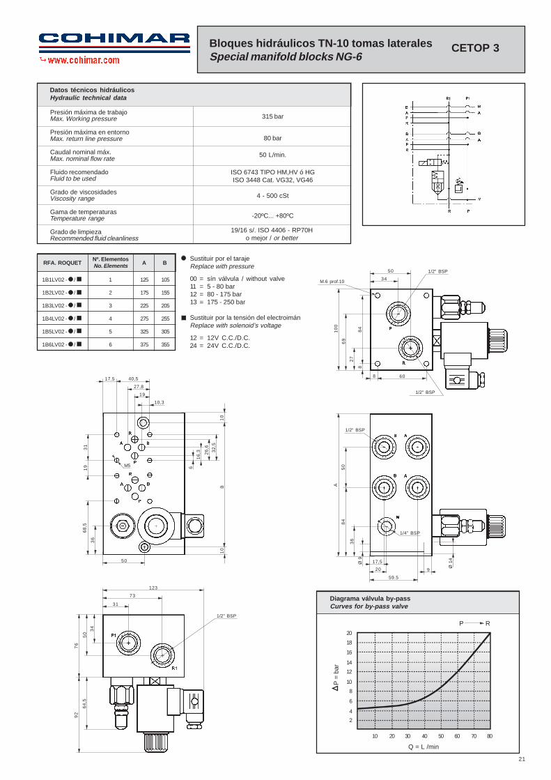
Bloques hidráulicos TN-10 tomas lateralesSpecial manifold blocks NG-6
ISO 6743 TIPO HM,HV ó HGISO 3448 Cat. VG32, VG46
4 - 500 cSt
-20ºC... +80ºC
315 bar
80 bar
50 L/min.
Datos técnicos hidráulicosHydraulic technical data
CETOP 3
19/16 s/. ISO 4406 - RP70Ho mejor / or better
1/4” BSP
34
50
M.6 prof.10
1/2” BSP
17,5
60
69
10
0
84
27
8
8
1/2” BSP
A
59.5
20 9
Ø 1
4
84
50
36
Ø 9
32
,5
17.5
10,3
34
50
76
64
,5
92
73
123
36
31
19
68
,5
50
40,5
27,8
19
31
M5 6
26
,6
16
,3
B1
01
0
1/2” BSP
1/2” BSP
1B1LV02 - / 1 125 105
1B2LV02 - / 2 175 155
1B3LV02 - / 3 225 205
1B4LV02 - / 4 275 255
1B5LV02 - / 5 325 305
1B6LV02 - / 6 375 355
RFA. ROQUETNº. ElementosNo. Elements A B
Sustituir por el tarajeReplace with pressure
00 = sín válvula / without valve11 = 5 - 80 bar12 = 80 - 175 bar13 = 175 - 250 bar
Sustituir por la tensión del electroimánReplace with solenoid’s voltage
12 = 12V C.C./D.C.24 = 24V C.C./D.C.
Diagrama válvula by-passCurves for by-pass valve
Q = L /min
10 20 30 40 50 60 70 80
2
4
6
20
18
16
14
12
10
8
P =
bar
P R
Max. Working pressure
Max. return line pressure
Max. nominal flow rate
Fluid to be used
Viscosity range
Temperature range
Recommended fluid cleanliness

22
Placa base múltiples TN-6 / Manifold blocks NG-6 CETOP 3
Nº ElementosNo. Elements
ReferenciaReference A
2
3
4
5
6
9869012
9869013
9869014
9869015
9869016
130
180
230
280
330
1/2 BSP
50
5 1840
A
50
58
Toma manómetroGauge port
P1
32
,53
2,5
32
,5
31
26,5
40
7,5
55
80 7,5
27
,5
7,5
42
7,5
38 19
10,3
==
23
26
,6
6
17
,51
7,5
95
1/2” BSP
8
M6 10Rosca utilUseful thread
M5 12Rosca utilUseful thread
1/4” BSP
23
40
Cuerpo válvula
Muelle de platillo
Tapón válvula
Junta tórica
Válvula retención
Juntas tóricas
Muelle
Muelle
Valve body
Disc-spring
Valve plug
O´Ring
Poppet valve
O´Rings
Spring
Spring
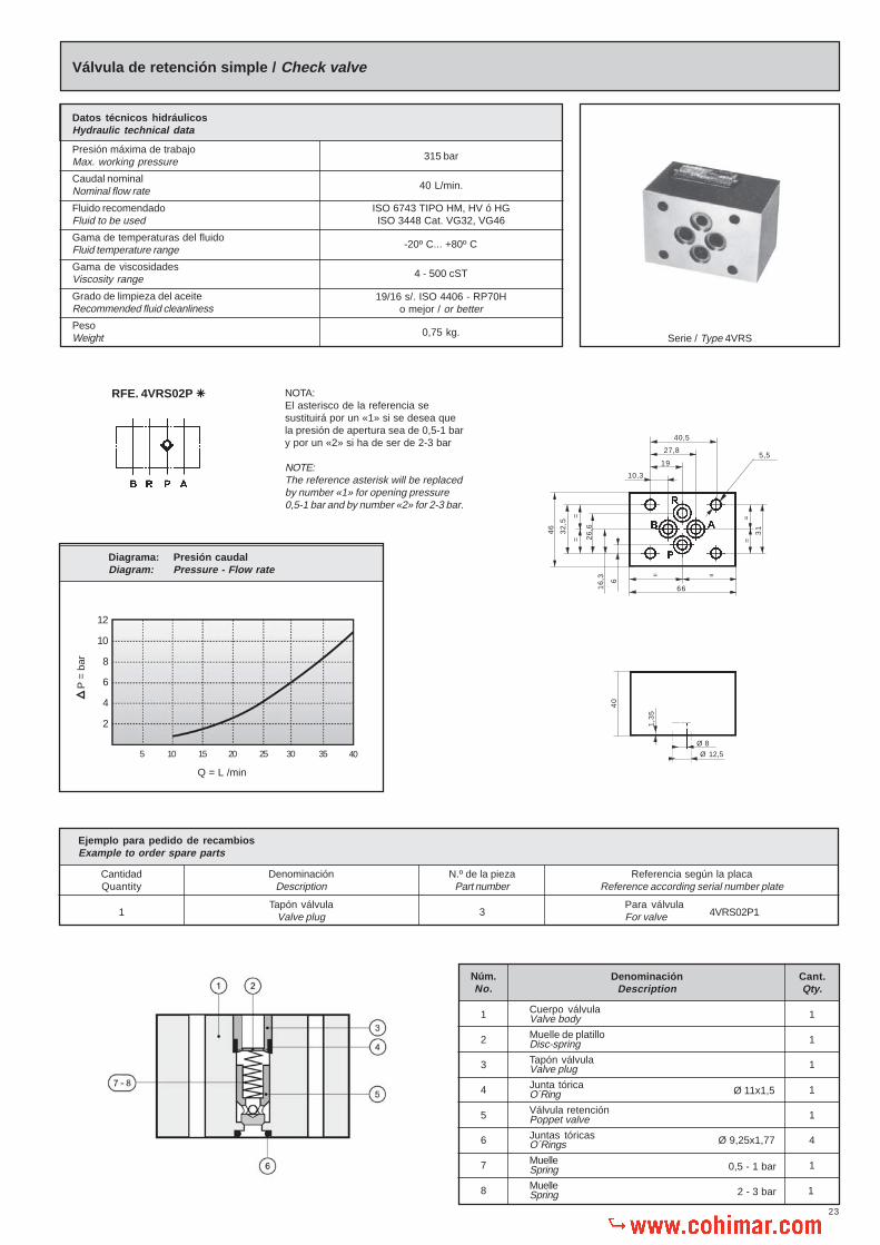
Válvula de retención simple / Check valve
Datos técnicos hidráulicosHydraulic technical data
Presión máxima de trabajoMax. working pressure
Caudal nominalNominal flow rate
Fluido recomendadoFluid to be used
Gama de temperaturas del fluidoFluid temperature range
Gama de viscosidadesViscosity range
Grado de limpieza del aceiteRecommended fluid cleanliness
PesoWeight
315 bar
40 L/min.
ISO 6743 TIPO HM, HV ó HGISO 3448 Cat. VG32, VG46
-20º C... +80º C
4 - 500 cST
19/16 s/. ISO 4406 - RP70Ho mejor / or better
0,75 kg.Serie / Type 4VRS
NOTA:El asterisco de la referencia sesustituirá por un «1» si se desea quela presión de apertura sea de 0,5-1 bary por un «2» si ha de ser de 2-3 bar
NOTE:The reference asterisk will be replacedby number «1» for opening pressure0,5-1 bar and by number «2» for 2-3 bar.
RFE. 4VRS02P �
Núm.No.
1
2
3
4
5
6
7
8
DenominaciónDescription
Cant.Qty.
1
1
1
1
1
4
1
1
0,5 - 1 bar
2 - 3 bar
Ø 9,25x1,77
Ø 11x1,5
46
66
= =
Ø 12,5
1,3
5
Ø 8
5,5
10,3
19
27,8
40,5
=
32
,5
= 26
,6
16
,3 6
==
31
Q = L /min
5 10 15 20 25 30 35
Diagrama: Presión caudalDiagram: Pressure - Flow rate
40
12
10
8
6
4
2
P =
bar
Tapón válvulaValve plug
Ejemplo para pedido de recambiosExample to order spare parts
CantidadQuantity
DenominaciónDescription
N.º de la piezaPart number
Referencia según la placaReference according serial number plate
1 3Para válvulaFor valve 4VRS02P1
24
Presión maxima de trabajo
Caudal nominal
Relación de descompresión
Fluido recomendado
Gama de temperaturas del fluido
Grado de viscosidades
Grado de limpieza del aceite
Peso
Max. Working pressure
Nominal flow rate
Decompression range
Fluid to be used
Fluid temperature range
Viscosity range
Recommended fluid cleanliness
Weight
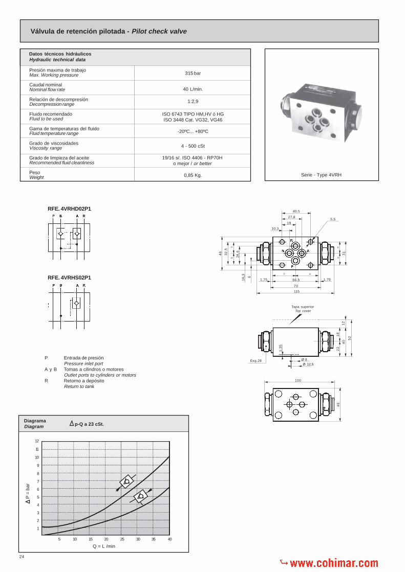
Válvula de retención pilotada - Pilot check valve
ISO 6743 TIPO HM,HV ó HGISO 3448 Cat. VG32, VG46
-20ºC... +80ºC
4 - 500 cSt
0,85 Kg.
315 bar
40 L/min.
1:2,9
Serie - Type 4VRH
Datos técnicos hidráulicosHydraulic technical data
P Entrada de presiónPressure inlet port
A y B Tomas a cilindros o motoresOutlet ports to cylinders or motors
R Retorno a depósitoReturn to tank
RFE. 4VRHS02P1
115
66,5
=
10,3
19
27,8
40,5
=
5,5
70
==
1,751,75
31
Tapa superiorTop cover
40
22
18
52
12
Exg.28
100
46
RFE. 4VRHD02P1
46
=
32
,5
16
,3 6
= 26
,6
Ø 12,5
1,3
5
Ø 8
DiagramaDiagram
12
11
10
9
8
7
6
5
4
3
2
1
Q = L /min
5 10 15 20 25 30 35 40
p-Q a 23 cSt.
P =
bar
19/16 s/. ISO 4406 - RP70Ho mejor / or better

25
RFE. 321001-321002-321031-321032
RFE. 321012
MuelleSpring
Ejemplo para pedido de recambiosExample to order spare parts
CantidadQuantity
DenominaciónDescription
N.º de la piezaPart number
Referencia según la placaReference according serial number plate
2 11Para válvulaFor valve 4VRHD02P1
Tapón
Junta metal-buna
Tapón válvula seguridad
Junta metal-buna
Junta tórica
Junta antiextrusión
Plug
Metal bonded gasket
Check valve plug
Metal bonded gasket
O´Ring
Anti-extrusion gasket
Embolo accionador
Curepo válvula
Juntas tóricas
Válvula
Muelle
Tapón
Piston
Valve body
O´Rings
Poppet
Spring
Plug
Núm.No.
1
2
3
4
5
6
DenominaciónDescription
Cant.Qty.
2
2
2
2
2
2
Núm.No.
7
8
9
10
11
12
DenominaciónDescription
Cant.Qty.
1
1
4
2
2
1
Ø 12x2
Ø 16x1,6x1
Ø 9,25x1,77
Según necesidadesAs per requirements
Accesorios Requieren pedido por separadoAccessories That need separate orders
4
4
Juntas tóricasO’rings
TornillosScrews
Ø 17 x 2
M5 x 55 DIN.912Par de aprieteTorque 7-8 Nm.
Placa base individual
Tapa superior
Juntas tóricas para montaje individual
Tornillos para fijación
Sub-plate
Top cover
O’rings for individual mounting
Screws for fixing

26
-20ºC... +80ºC
4 - 500 cSt
0,85 Kg.
Max. Working pressure
Nominal flow rate
Fluid to be used
Fluid temperature range
Viscosity range
Recommended fluid cleanliness
Weight
Presión maxima de trabajo
Caudal nominal
Fluido recomendado
Gama de temperaturas del fluido
Grado de viscosidades
Grado de limpieza del aceite
Peso
Estrangulador doble con válvula retención - Double throttle valve with check valve
ISO 6743 TIPO HM,HV ó HGISO 3448 Cat. VG32, VG46
315 bar
20 L/min.
Serie - Type 2EGD
Datos técnicos hidráulicosHydraulic technical data
Sentido A1 - A, B1 - B con el estrangulador cerrado.Sense A1 - A, B1 - B with closed throttle valve.
106
20,5
284
0
27,5
120
4
P Entrada de presiónPressure inlet port
A y B Tomas a cilindros o motoresOutlet ports to cylinders or motors
R Retorno a depósitoReturn to tank
Tapa superiorTop cover
65
RegulaciónAdjustment
31
27,5
==
RFE: 2EGD02P2
RFE: 2EGD02P1
Ø 121,6
Ø 6,5
10,3
19
27,8
40,5
5,5
=
32
,5
16
,3
6
= 26
,6
65
==
31
==
20,5
46
12
19/16 s/. ISO 4406 - RP70Ho mejor / or better
Regulación formaAdjustment type 2
Regulación formaAdjustment type 1
Q = L /min
Diagrama:Diagram: p-Q a 23 cSt.
10
8
6
4
2
2 4 6 8 10 12 14 16 18 20
Sentido A - A1, B - B1 con el estrangulador abierto al máximo.Sense A - A1, B - B1 with throttle valve max.opened.
p =
bar
5
4
3
2
1
Q = L /min
2 4 6 8 10 12 14 16 18 20
Diagrama:Diagram: p-Q a 23 cSt.
p =
bar

27
RFE. 321001-321002-321031-321032
RFE. 321013
Volante regulaciónAdjusting knob
Ejemplo para pedido de recambiosExample to order spare parts
CantidadQuantity
DenominaciónDescription
N.º de la piezaPart number
Referencia según la placaReference according serial number plate
2 2Para válvulaFor valve 2EGD02P2
Ball stop elastic pin
Metal bonded gasket
Adjusting screw
Plugs and screw guides
Nut
Adjusting screw
Pasador elástico tope bola
Junta metal-buna
Tornillo estrangulador
Tapón guía tornillo estrangulador
Contratuerca
Tornillo estrangulador
2
2
2
2
2
1
4
1
2
3
4
5
6
7
Núm.No.
DenominaciónDescription
Cant.Qty.
DIN-1481 Ø 2x20
Ø 3,4x1,9
Ø 8x12x2
Elastic pin
Adjustig knob
Plugs and screw guides
Balls
O’ring
Valve body
O’ring
Pasador elástico
Volante regulación
Tapón guía tornillo estrangulador
Bolas
Junta tórica
Cuerpo válvula
Junta tórica
2
2
2
2
2
2
8
9
10
11
12
13
Núm.No.
DenominaciónDescription
Cant.Qty.
Ø 6,5
Según necesidadesAs per requirements
Accesorios Requieren pedido por separadoAccessories That need separate orders
2
4
Juntas tóricasO’rings
TornillosScrews
Ø 17 x 2
M5 x 45 DIN.912Par de aprieteTorque 7-8 Nm.
Placa base individual
Tapa superior
Juntas tóricas para montaje individual
Tornillos para fijación
Sub-plate
Top cover
O’rings for individual mounting
Screws for fixing

28
=
P Entrada de presiónPressure inlet port
A y B Tomas a cilindros o motoresOutlet ports to cylinders or motors
R Retorno a depósitoReturn to tank
Presión maxima de trabajo
Caudal nominal
Caudal minimo regulable
Fluido recomendado
Gama de temperaturas del fluido
Grado de viscosidades
Grado de limpieza del aceite
Peso
Max. Working pressure
Nominal flow rate
Min, controlled flow
Fluid to be used
Fluid temperature range
Viscosity range
Recommended fluid cleanliness
Weight
Estrangulador doble con válvula retención - Double throttle valve with check valve
ISO 6743 TIPO HM,HV ó HGISO 3448 Cat. VG32, VG46
-20ºC... +80ºC
4 - 500 cSt
1,350 Kg.
315 bar
40L /min.
600 cm³/min.
Serie - Type 4EG
Datos técnicos hidráulicosHydraulic technical data
˜
RFE: 4EGD02P
RFE: 4EGS02P
97
174
70
40
16
,3
=
Tapa superiorTop cover
46
=
32
,5
6
26
,6
52
12
18
22
7
RegulaciónAdjustment
8,5
RegulaciónAdjustment
8,5
Ø 3
6
257Cota necesaria para la extracción de la llaveMinimum dimension to remove key
1,7566,5
70
==
1,75
65,5 65,5
201
==
10,3
19
27,8
40,5
5,5
31
1,3
5 Ø 8Ø 12,5
150
140
130
120
110
100
90
80
70
60
50
40
30
20
10
Q = L /min
10 20 30 40 50 60 70 80
N.º de vueltas volante / Number of knob turns2 1/2 3 3 1/2 4 4 3/4 5 3 /44 1/2
5 1/2
6
6 1/2
DiagramaDiagram p-Q a 23 cSt.
Q = L /min
1
2
5 10 15 20 25 30 35 40 45
20
18
16
14
12108642
Sentido del flujo libre con el estrangulador cerrado (1) ó abierto (2)
50
DiagramaDiagram p-Q a 23 cSt.
P =
bar
P =
bar
Free flow sense, with knob fully closed (1) or open (2)
19/16 s/. ISO 4406 - RP70Ho mejor / or better
Regulación formaAdjustment type 2
Regulación formaAdjustment type 3-4
29
RFE. 321001-321002-321031-321032
RFE. 321013
Ø 9,25 x1,77
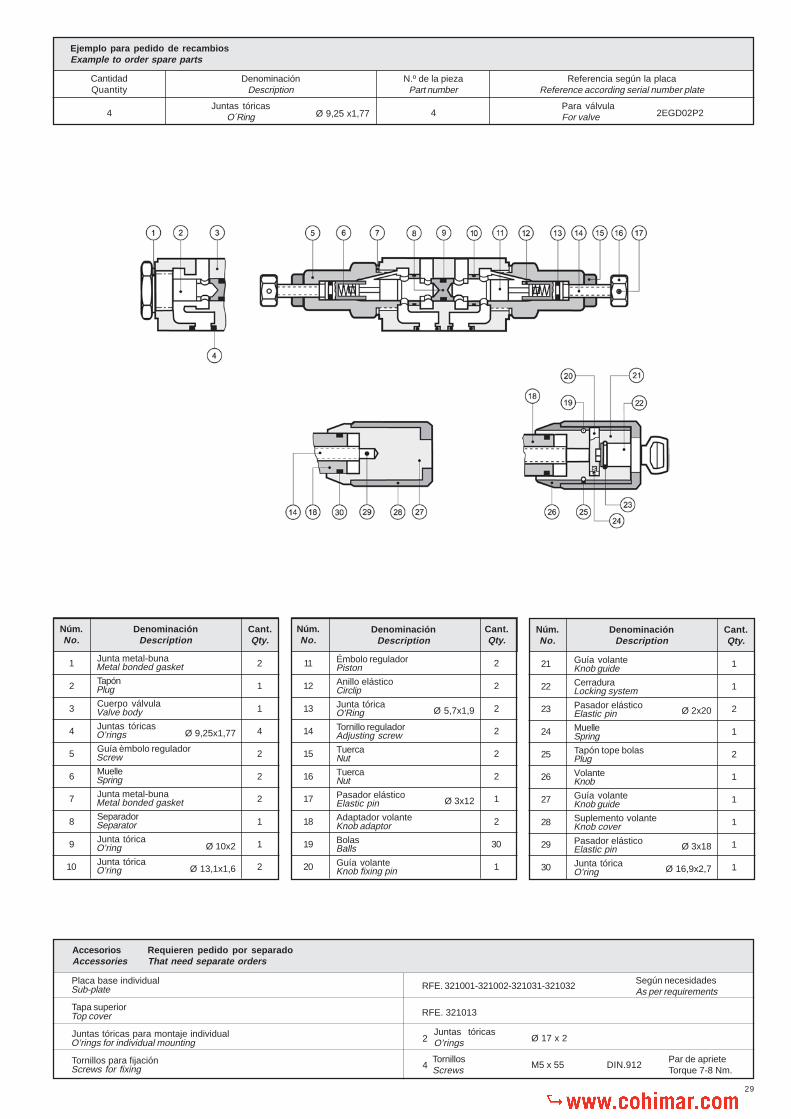
Ejemplo para pedido de recambiosExample to order spare parts
CantidadQuantity
DenominaciónDescription
N.º de la piezaPart number
Referencia según la placaReference according serial number plate
4Juntas tóricas
O´Ring 4Para válvulaFor valve 2EGD02P2
Junta metal-buna
Tapón
Cuerpo válvula
Juntas tóricas
Guía èmbolo regulador
Muelle
Junta metal-buna
Separador
Junta tórica
Junta tórica
Metal bonded gasket
Plug
Valve body
O’rings
Screw
Spring
Metal bonded gasket
Separator
O’ring
O’ring
Núm.No.
1
2
3
4
5
6
7
8
9
10
DenominaciónDescription
Cant.Qty.
2
1
1
4
2
2
2
1
1
2
Ø 9,25x1,77
Ø 10x2
Ø 13,1x1,6
Émbolo regulador
Anillo elástico
Junta tórica
Tornillo regulador
Tuerca
Tuerca
Pasador elástico
Adaptador volante
Bolas
Guía volante
Piston
Circlip
O’Ring
Adjusting screw
Nut
Nut
Elastic pin
Knob adaptor
Balls
Knob fixing pin
Ø 5,7x1,9
Ø 3x12
Núm.No.
11
12
13
14
15
16
17
18
19
20
DenominaciónDescription
Cant.Qty.
2
2
2
2
2
2
1
2
30
1
Guía volante
Cerradura
Pasador elástico
Muelle
Tapón tope bolas
Volante
Guía volante
Suplemento volante
Pasador elástico
Junta tórica
Knob guide
Locking system
Elastic pin
Spring
Plug
Knob
Knob guide
Knob cover
Elastic pin
O’ring
Ø 2x20
Ø 3x18
Ø 16,9x2,7
Núm.No.
21
22
23
24
25
26
27
28
29
30
DenominaciónDescription
Cant.Qty.
1
1
2
1
2
1
1
1
1
1
Núm.No.
DenominaciónDescription
Cant.Qty.
Según necesidadesAs per requirements
Accesorios Requieren pedido por separadoAccessories That need separate orders
2
4
Juntas tóricasO’rings
TornillosScrews
Ø 17 x 2
M5 x 55 DIN.912Par de aprieteTorque 7-8 Nm.
Placa base individual
Tapa superior
Juntas tóricas para montaje individual
Tornillos para fijación
Sub-plate
Top cover
O’rings for individual mounting
Screws for fixing
30
Ø 12,5
7,5
Ø 3
6
Tapa superiorTop cover
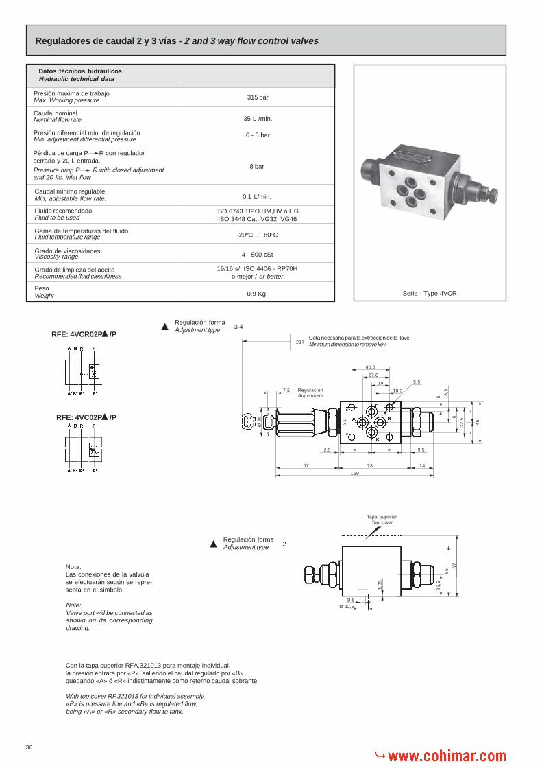
Con la tapa superior RFA.321013 para montaje individual,la presión entrará por «P», saliendo el caudal regulado por «B»quedando «A» ó «R» indistintamente como retorno caudal sobrante
With top cover RF.321013 for individual assembly,«P» is pressure line and «B» is regulated flow,being «A» or «R» secondary flow to tank.
RFE: 4VC02P /P
RFE: 4VCR02P /P
Presión maxima de trabajo
Caudal nominal
Presión diferencial min. de regulación
Caudal mínimo regulable
Fluido recomendado
Gama de temperaturas del fluido
Grado de viscosidades
Grado de limpieza del aceite
Peso
Min, adjustable flow rate.
Fluid to be used
Fluid temperature range
Viscosity range
Recommended fluid cleanliness
Weight
Max. Working pressure
Nominal flow rate
Min. adjustment differential pressure
8 bar
0,1 L/min.
Reguladores de caudal 2 y 3 vías - 2 and 3 way flow control valves
315 bar
35 L /min.
6 - 8 bar
Serie - Type 4VCR
Datos técnicos hidráulicosHydraulic technical data
Pérdida de carga P R con reguladorcerrado y 20 l. entrada.
Pressure drop P R with closed adjustmentand 20 lts. inlet flow
ISO 6743 TIPO HM,HV ó HGISO 3448 Cat. VG32, VG46
-20ºC... +80ºC
4 - 500 cSt
0,9 Kg.
Cota necesaria para la extracción de la llaveMinimum dimension to remove key
Ø 8
1,3
5
67
55
26
,5
40,5
27,8
19
10,3
5,5
31
2467
169
78
26
,6
16
,3
==
32
,5
46
6
== 9,52,5
217
RegulaciónAdjustment
Nota:Las conexiones de la válvulase efectuarán según se repre-senta en el símbolo.
Note:Valve port will be connected asshown on its correspondingdrawing.
19/16 s/. ISO 4406 - RP70Ho mejor / or better
Regulación formaAdjustment type 2
Regulación formaAdjustment type 3-4
31
RFE. 321001-321002-321031-321032
RFE. 321013
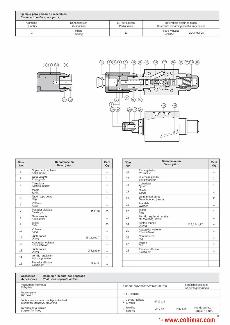
MuelleSpring
Ejemplo para pedido de recambiosExample to order spare parts
CantidadQuantity
DenominaciónDescription
N.º de la piezaPart number
Referencia según la placaReference according serial number plate
1 19Para válvulaFor valve 2VCR02P2/P
Estrangulador
Cuerpo regulador
Corredera
Muelle
Junta metal-buna
Arandela
Tapón
Tornillo regulación aceite
Juntas tóricas
Adaptador volante
Contratuerca
Tuerca
Pasador elástico
Suplemento volante
Guía volante
Cerradura
Muelle
Tapón tope bolas
Volante
Pasador elástico
Guía volante
Bolas
Volante
Junta tórica
Adaptador volante
Junta tórica
Tornillo regulación
Pasador elástico
Restrictor
Valve housing
Spool
Spring
Metal bonded gasket
Washer
Plug
Oil throttling screw
O’rings
Knob adaptor
Nut
Nut
Elastic pin
1
2
3
4
5
6
7
8
9
10
11
12
13
14
15
DenominaciónDescription
Núm.No.
Cant.Qty.
1
1
1
1
1
1
2
1
30
1
1
1
1
1
1
16
17
18
19
20
21
22
23
24
25
26
27
28
DenominaciónDescription
Núm.No.
Cant.Qty.
1
1
1
1
2
1
1
1
4
1
1
1
1
Ø 9,25x1,77
Ø 3x18
Ø 8,9x1,9
Ø 16,9x2,7
Ø 2x20
Knob cover
Knob guide
Locking system
Spring
Plug
Knob
Elastic pin
Knob guide
Balls
Knob
O’ring
Knob adaptor
O’ring
Adjusting screw
Elastic pin
Según necesidadesAs per requirements
Accesorios Requieren pedido por separadoAccessories That need separate orders
2
4
Juntas tóricasO’rings
TornillosScrews
Ø 17 x 2
M5 x 70 DIN.912Par de aprieteTorque 7-8 Nm.
Placa base individual
Tapa superior
Juntas tóricas para montaje individual
Tornillos para fijación
Sub-plate
Top cover
O’rings for individual mounting
Screws for fixing

32
Presión maxima de trabajo
Caudal nominal
Presión diferencial min. de regulación
Caudal minimo regulable
Fluido recomendado
Gama de temperaturas del fluido
Grado de viscosidades
Grado de limpieza del aceite
Peso
7,5
2,5
67
4,5
73
164
==
5,5
24
Cota necesaria para la extracción de la llaveMinimum dimension to remove key
Ø 8Ø 12,5
1,3
5
67
55
23
= =
32
,5 16
,3
6
26
,6
==
46
==
31
40,5
10,3
19
27,8
134
RFE: 4VCR02P /B
Tapa superiorTop cover
212
Montando las placas321006 y 321007se invierte elsentido de regulación.
Adjusment senseis invertedby mountingsub-plates321006 and 321007
Nota.Las conexiones de la válvulase efectuarán según se presenta enel símbolo.
Note:Valve ports will beconnected as shownon correspondingdrawing.
Max. Working pressure
Nominal flow rate
Min. adjustment differential pressure
Min. controlled flow rate
Fluid to be used
Fluid temperature range
Viscosity range
Recommended fluid cleanliness
Weight
Regulador de caudal 2 vías - 2 way flow control valves
-20ºC... +80ºC
4 - 500 cSt
0,95 Kg.
315 bar
35 L /min.
8 - 10 bar
0,1 L/min.
Serie - Type 4VCR
Datos técnicos hidráulicosHydraulic technical data
ISO 6743 TIPO HM,HV ó HGISO 3448 Cat. VG32, VG46
19/16 s/. ISO 4406 - RP70Ho mejor / or better
Rfa. 321006
Rfa. 321007
Regulación formaAdjustment type 2
Regulación formaAdjustment type 3-4
RFE: 4VCR02P /A
Regulación tomaOutlet adjustment B
Regulación tomaOutlet adjustment A

33
RFE. 321001-321002-321031-321032
RFE. 321013
Tapón tope bolas
Volante
Tornillo regulación
Adaptador volante
Junta tórica
Estrangulador
Juntas tóricas
Tornillo regulación aceite
Junta metal-buna
Tapón
Tuerca
Corredera
Guía muelle
Muelle
Junta tórica
Pasador elástico
Suplemento volante
Volante
Adaptador volante
Contratuerca
Tuerca
Pasador elástico
Spring guide
Spring
O’ring
Elastic pin
Knob cover
Knob
Knob adaptor
Nut
Nut
Elastic pin
Plug
Knob
Adjusting screw
Knob adaptor
O’ring
Restrictor
O’rings
Oil throttling screw
Metal bonded gasket
Plug
Nut
Spool
DenominaciónDescription
3
4
2
6
7
8
9
10
11
12
5
1
Núm.No.
Cant.Qty.
1
1
1
1
1
1
30
1
1
1
2
1
DenominaciónDescription
15
16
14
18
19
20
21
22
23
24
17
13
Núm.No.
Cant.Qty.
1
1
1
1
1
1
4
1
2
1
1
1
DenominaciónDescription
27
28
26
30
31
32
33
34
29
25
Núm.No.
Cant.Qty.
2
1
1
1
1
1
1
1
1
1
Ø 3x18
Ø 16,9x2,7
Ø 3x12
Ø 8,9x1,9
Ø 9,25x1,77
Ø 8x1,6
Ø 2x10
Ø 2x20
Guía muelleSpring guide
Ejemplo para pedido de recambiosExample to order spare parts
CantidadQuantity
DenominaciónDescription
N.º de la piezaPart number
Referencia según la placaReference according serial number plate
2 25Para válvulaFor valve 4VCR02P3/A
Cuerpo regulador
Válvula retención
Muelle
Junta tórica
Tapón válvula
Pasador
Bolas
Guía volante
Guía volante
Cerradura
Pasador
Muelle
Valve housing
Check valve
Spring
O’ring
Plug
Pin
Balls
Knob guide
Knob guide
Locking system
Pin
Spring
Según necesidadesAs per requirements
Accesorios Requieren pedido por separadoAccessories That need separate orders
2
4
Juntas tóricasO’rings
TornillosScrews
Ø 17 x 2
M5 x 70 DIN.912Par de aprieteTorque 7-8 Nm.
Placa base individual
Tapa superior
Juntas tóricas para montaje individual
Tornillos para fijación
Sub-plate
Top cover
O’rings for individual mounting
Screws for fixing

34
30
28
26
24
22
20
18
16
14
12
10
8
6
4
2
10 30 50 90 110 21070 130 150 170 190 230 250
26
24
22
20
18
16
14
12
10
8
6
4
2
Presión entrada / Inlet pressure bar
Reguladores de caudal 3 vías - 3 way flow control valves
Reguladores de caudal 2 vías - 2 way flow control valves
24
22
20
18
16
14
12
10
8
6
4
2
p =
bar
5 10 15 2520
Regulador cerradoClosed flow controlvalve
Regulador abierto almáximoFlow control valvefully open
Q = I/min.
Curva sensibilidad flujo controladoMetering curve
Nº de vueltas / Turns
Diagrama: Presión caudalDiagram: Pressure-flow rate
Cau
dal s
alid
a re
gula
da l/
min
.O
utpu
t co
ntro
lled
flow
rat
e l/m
in.
0,5
22
20
18
16
14
12
10
8
6
4
2
1 1,5 2,55
2 3 3,5 4 4,5
20
18
16
14
12
10
8
6
4
2
10 30 50 90 110 21070 130 150 170 190 230 250
Presión entrada / Inlet pressure bar
Cau
dal s
alid
a re
gula
da l/
min
.O
utpu
t con
trol
led
flow
rat
e l/m
in.
Diagrama: Presión caudalDiagram: Pressure-flow rate
Q =
L /
min
Curva sensibilidadMetering curve
Nº de vueltas / Turns
0,5 1 1,5 2,5 52 3 3,5 4 4,5

35
Accionamiento manual por palanca - Manually operated
Serie / Type 4MV
Datos técnicos hidráulicosHydraulic technical data
Presión máxima de trabajoMax. working pressure
Caudal nominalNominal flow rate
Fluido recomendadoFluid to be used
Gama de temperaturas del fluidoFluid temperature range
Gama de viscosidadesViscosity range
Grado de limpieza del aceiteRecommended fluid cleanlinessPesoWeight
315 bar
50 L/min.
ISO 6743 TIPO HM, HV ó HGISO 3448 Cat. VG32, VG46
-20º C... +80º C
4 - 500 cST
1 kg.
Carrera correderaSpool stroke
3 mm.
Presión nominal en retornoNominal pressure in return
80 bar
Para presiones superiores consultar.For higher pressure please consult.
Nota: Para diagrama p-Q ver gráfico pág.5Note: For diagram p-Q see curves pag.5
Distribuidor TN-6Directional control valve NG-6
40
27,8
141,5
4035 66,5
46
10
7,5
Ø9 13
0,5
47
23
= =
10º 10º
40,5
19
10,3
5,5
26
,6
16
,3
==
32
,5
6
==
Ø 12,51,3
5 Ø 8
1
19/16 s/. ISO 4406 - RP70Ho mejor / or better
P Entrada de presiónPressure inlet port
A y B Tomas a cilindros o motoresOutlet ports to cylinders or motors
R Retorno a depósitoReturn to tank
CETOP 3

36
A, B y P (1) R
A y B (2)
A y B (2)
A y B (1) R
A,B y P (1)
A (1) R
B y P (1) R
A y B (2)
A y B (2)
A y B (1) R
A (1) R
B y P (1) R
P (1) R
P y R (2)
P (2)
R
B y P (2)
A (2)
P (1) R
P y R (2)
P (2)
B y P (2)
A (2)
(1) Comunica / Connect.(2) Cerrado / Closed.
4MVP10D1C02
4MVP10D2C02
4MVP10D3C02
4MVP10D4C02
4MVP10D5C02
4MVP10D6C02
4MVP5D1C02
4MVP5D2C02
4MVP5D3C02
4MVP5D4C02
4MVP5D5C02
4MVP5D6C02
4MVP6D7C02
4MVP6D8C02
4MVP6D17B02
4MVP6D18C02
4MVP7D1C02
4MVP7D2C02
4MVP7D3C02
4MVP7D4C02
4MVP7D5C02
4MVP7D6C02
4MVP11D1C02
4MVP11D2C02
4MVP11D3C02
4MVP11D4C02
4MVP11D5C02
4MVP11D6C02
4MVP9D2C02
Circulación de aceiteConnections
ReferenciaReference
Formade la
corredera Spoolform
SímboloSymbol
P (1) B A (1) R
P (1) A B (1) R P (1) B A (1) R
1
2
3
4
5
6
1
2
3
4
5
6
7
8
17
18
1
2
3
4
5
6
1
2
3
4
5
6
2
PosiciónPosition 1
PosiciónPosition 0
PosiciónPosition 2
P (1) B A (1) RP (1) A B (1) R
P (1) A B y R (2)
P (1) A B (1) R
P (1) B A y R (2)
P (1) B A (1) R
P (1) A B (1) R
P (1) B A y R (2)
P (1) B A (1) R
P (1) A B y R (2)
P (1) A R (1) R
P (1) B A (1) R
P (1) A B (1) R
P (1) A B (1) R
P (1) B A (1) R
A, B y P (1) R
A, B y P (1) R
A y B (2)
A y B (2)
A y B (1) R
A (1) R
B y P (1) R
A y B (2)
A y B (2)
A y B (1) R
A (1)
B y P (1) R
P(1) R
P y R (2)
P (2)
B y P (2)
A (2)
P (1) R
P y R (2)
P (2)
B y P (2)
A (2)

37
Lever knob
Lever
Dust protector
Fixing lever pin
Support lever cover
Spool head
Screws
Washer
O’rings
Spool
Back cover
Puño palanca mando
Palanca mando
Protector polvo
Pasador fijación palanca
Tapa soporte palanca
Cabeza corredera
Tornillos
Arandela
Juntas tóricas
Corredera
Tapa posterior
DIN - 912 M4x12
DIN - 7980 Ø 4
Ø 9,25x1,77
RFE. 321001-321002
M5 x 50 DIN-912
Placa base individual
Tornillos para fijación
Sub-plate
Screws for fixing
Accesorios Requieren pedido por separadoAccessories That need separate orders
Según necesidadesAs per requirements
4TornillosScrews
Par de aprieteTorque 7-8 Nm.
MuelleSpring
Ejemplo para pedido de recambiosExample to order spare parts
CantidadQuantity
DenominaciónDescription
N.º de la piezaPart number
Referencia según la placaReference according serial number plate
1 12Para válvulaFor valve 4MVP5D1C02
Núm.No.
1
2
3
4
5
6
7
8
9
10
11
DenominaciónDescription
Cant.Qty.
1
1
1
1
1
1
8
8
4
1
1
Spring
Elastic ring
Spring guide stop
Spring guide
Screws
Serial number plate
Valve body
O’rings
Cover guides
O’rings
Spring guide
Núm.No.
12
13
14
15
16
17
18
19
20
21
22
DenominaciónDescription
Cant.Qty.
1
1
1
2
4
1
1
2
2
2
1
Muelle
Anillo elástico
Pieza tope guía muelle
Guía muelle
Tornillos
Placa referencias
Cuerpo distribuidor
Juntas tóricas
Piezas guía tapas
Juntas tóricas
Guía muelle
M3x5
Ø 15,6x1,78
Ø 11,5x1,5
Spring stop washer
Spring guide
Spring guide stop part
Detent fixing part
Detent fixing part
Ball ring
Ball stop bush
Detent balls
Spring
Spool stop
Arandela tope muelle
Guía muelle
Tope guía muelle
Pieza anclajes
Pieza anclajes
Anillo apriete bolas
Anillo tope bolas
Bolas anclaje
Muelle
Tope corredera
(3 pos.)
(2 pos.)
Ø 2
(2 pos.)
Núm.No.
23
24
25
26
27
28
29
30
31
32
DenominaciónDescription
Cant.Qty.
1
1
1
1
1
1
1
17
1
1

38
Nota: Para diagrama p-Q ver gráfico pág.5Note: For diagram p-Q see curves pag.5
Accionamiento por tirador de mano manual - Manually knob operated
Serie / Type 4PV
Datos técnicos hidráulicosHydraulic technical data
Presión máxima de trabajoMax. working pressure
Caudal nominalNominal flow rate
Fluido recomendadoFluid to be used
Gama de temperaturas del fluidoFluid temperature range
Gama de viscosidadesViscosity range
Grado de limpieza del aceiteRecommended fluid cleanlinessPesoWeight
315 bar
50 L/min.
ISO 6743 TIPO HM, HV ó HGISO 3448 Cat. VG32, VG46
-20º C... +80º C
4 - 500 cST
19/16 s/. ISO 4406 - RP70Ho mejor / or better
1 kg.
Carrera correderaSpool stroke
6 mm.
Presión nominal en retornoNominal pressure in return
80 bar
Para presiones superiores consultar.For higher pressure please consult.
4PVP6D7B02
4PVP6D8C02
4PVP6D17B02
4PVP6D18C02
4PVP9D7B02
4PVP9D8C02
4PVP9D17B02
4PVP9D18C02
Circulación de aceiteConnections
ReferenciaReference
Formade la
corredera Spoolform
SímboloSymbol
7
8
17
18
7
8
17
18
PosiciónPosition 1
PosiciónPosition 2
P (1) B A y R (2)
P (1) B A (1) R
P (1) A B y R (2)
P (1) A B (1) R
P (1) B A y R (2)
P (1) B A (1) R
P (1) A B y R (2)
P (1) A B (1) R
P (1) A B y R (2)
P (1) A B (1) R
P (1) B A y R (2)
P (1) B A (1) R
P (1) A B y R (2)
P (1) A B (1) R
P (1) B A y R (2)
P (1) B A (1) R
47
145
4038,5 66,5
PosiciónPosition 1
PosiciónPosition 2
CarreraStroke 6 mm.
Ø 3
8
40
Ø 9
P Entrada de presiónPressure inlet port
A y B Tomas a cilindros o motoresOutlet ports to cylinders or motors
R Retorno a depósitoReturn to tank
31
40,5
27,8
19
10,3
5,5
16
,3
==
6
==
32
,5
46
==
Ø 12,51,3
5 Ø 8
1
26
,6
(1) Comunica / Connect. (2) Cerrado / Closed.

39
M5 x 50 DIN-912
PuñoKnob
Ejemplo para pedido de recambiosExample to order spare parts
CantidadQuantity
DenominaciónDescription
N.º de la piezaPart number
Referencia según la placaReference according serial number plate
1 1Para válvulaFor valve 4PVP6D7B02
Knob
Screws
Washer
Valve body
Serial number plate
Screws
Spring guide
Spring
Back cover
Spring guide stop
Elastic ring
Spring stop washer
Puño
Tornillos
Arandela
Cuerpo distribuidor
Placa referencias
Tornillos
Guía muelle
Muelle
Tapa posterior
Pieza tope guía muelle
Anillo elástico
Arandela tope muelle
Núm.No.
1
2
3
4
5
6
7
8
9
10
11
12
DenominaciónDescription
Cant.Qty.
1
8
8
1
1
4
1
1
1
1
1
1
13
14
15
16
17
18
19
20
21
22
23
24
DenominaciónDescription
Núm.No.
Cant.Qty.
1
2
1
4
1
1
1
1
1
17
1
1
DIN-912 M4x12
DIN-7980 Ø4
M3X5
Placa base individual
Tornillos para fijación
Sub-plate
Screws for fixing
Accesorios Requieren pedido por separadoAccessories That need separate orders
RFE. 321001-321002Según necesidadesAs per requirements
4TornillosScrews
Par de aprieteTorque 7-8 Nm.
Pieza guía tapas
Juntas tóricas
Corredera
Juntas tóricas
Tapa anterior
Juntas tóricas
Anillo rascador polvo
Anillo apriete bolas
Anillo tope bolas
Bolas anclaje
Muelle
Piezas fijación anclajes
Cover guides
O’rings
Spool
O’rings
Front cover
O’rings
Dust scraper
Ball rings
Ball stop bush
Detent balls
Spring
Detent fixing parts
Ø 2
Ø 11,5x1,5
Ø 9,25x1,77
Ø 15,6x1,78

40
40
27,8
158,5
4052 66,5
18
20
Ø 9 4,5
==
40,5
19
10,3
31
16
,3
==
6
26
,6
==
32
,5
47
23
1
Ø 12,5
Ø 8
1,3
5
24º41º45º
Posición delanteraFront position
Posición traseraBack position
23
Tornillo de ajusteAdjusting screw
41
27
47
˜˜
Accionamiento por un rodillo - Single roller operated
Serie / Type 4RV
Datos técnicos hidráulicosHydraulic technical data
Presión máxima de trabajoMax. working pressure
Caudal nominalNominal flow rate
Fluido recomendadoFluid to be used
Gama de temperaturas del fluidoFluid temperature range
Gama de viscosidadesViscosity range
Grado de limpieza del aceiteRecommended fluid cleanlinessPesoWeight
315 bar
50 L/min.
ISO 6743 TIPO HM, HV ó HGISO 3448 Cat. VG32, VG46
-20º C... +80º C
4 - 500 cST
19/16 s/. ISO 4406 - RP70Ho mejor / or better
1,2 kg.
Carrera correderaSpool stroke
6 mm.
Presión nominal en retornoNominal pressure at return
80 bar
Para presiones superiores consultar.For higher pressure please consult.
P Entrada de presiónPressure inlet port
A y B Tomas a cilindros o motoresOutlet ports to cylinders or motors
R Retorno a depósitoReturn to tank
Nota: Para diagrama p-Q ver gráfico pág.5Note: For diagram p-Q see curves paf.5
4RVP6D7B02
4RVP6D8C02
4RVP6D17B02
4RVP6D18C02
Circulación de aceiteConnections
ReferenciaReference
Formade la
corredera Spoolform
SímboloSymbol
7
8
17
18
Posición delanteraFront position
Posición traseraBack position
P (1) B A y R (2)
P (1) B A (1) R
P (1) A B y R (2)
P (1) A B (1) R
P (1) A B y R (2)
P (1) A B (1) R
P (1) B A y R (2)
P (1) B A (1) R
(1) Comunica / Connect. (2) Cerrado / Closed.
5,5

41
Anillo rascador polvoDust scraper
Placa base individual
Tornillos para fijación
Sub-plate
Screws for fixing
Accesorios Requieren pedido por separadoAccessories That need separate orders
RFE. 321001-321002Según necesidadesAs per requirements
4TornillosScrews M5 x 50 DIN-912
Par de aprieteTorque 7-8 Nm.
Arandelas de accionamiento
Cabeza corredera
Tornillos
tornillos
Arandelas
Cuerpo distribuidor
Placa referencias
Tornillos
Guía muelle
Guía muelle
Arandela tope muelle
Anillo estástico
Pieza tope guía muelle
Tapa posterior
Pieza guía tapas
Juntas tóricas
Corredera
Juntas tóricas
Juntas tóricas
Anillo rascador polvo
Tapa anterior
1
2
3
4
5
6
7
8
9
10
11
12
13
14
15
16
17
18
19
20
21
Núm.No.
Operating assembly
Spool head
Screws
Screws
Washers
Valve body
Serial number plate
Screws
Spring guide
Spring guide
Spring stop washer
Núm.No.
DenominaciónDescription
Cant.Qty.
1
1
4
8
8
1
1
4
1
1
1
M3x5
M4x10
DIN-912 M4x12
DIN-7980 Ø4
Elastic ring
Spring guide stop
Back cover
Cover guides
O’rings
Spool
O’rings
O’rings
Dust scraper
Front cover
Núm.No.
DenominaciónDescription
Cant.Qty.
1
1
1
1
2
1
4
2
1
1
Ø 11,5x1,5
Ø 9,25x1,77
Ø 15,6x1,78
Ejemplo para pedido de recambiosExample to order spare parts
CantidadQuantity
DenominaciónDescription
N.º de la piezaPart number
Referencia según la placaReference according serial number plate
1 20Para válvulaFor valve 4RVP6D7B02

42
40
27,8
809
0
23
==
31
=
4R2VP9D7B02
4R2VP9D8C02
4R2VP9D17B02
4R2VP9D18C02
Circulación de aceiteConnection
ReferenciaReference
Formade la
corredera Spoolform
SímboloSymbol
7
8
17
18
Posición delanteraFront position
Posición traseraBack position
P (1) B A y R (2)
P (1) B A (1) R
P (1) A B y R (2)
P (1) A B (1) R
P (1) A B y R (2)
P (1) A B (1) R
P (1) B A y R (2)
P (1) B A (1) R
(1) Comunica / Connect. (2) Cerrado / Closed.
P Entrada de presiónPressure inlet port
A y B Tomas a cilindros o motoresOutlet ports to cylinders or motors
R Retorno a depósitoReturn to tank
40,5
19
10,3
141,5
40
==
35 66,5
16
,3
=
6
32
,5
4,5
14
7
46
= =
Ø 9
Posición traseraBack position
Posición delanteraFront position
31
30´8 º
Ø 12,5
Ø 8
1,3
5
Serie / Type 4R2V
Datos técnicos hidráulicosHydraulic technical data
Presión máxima de trabajoMax. working pressure
Caudal nominalNominal flow rate
Fluido recomendadoFluid to be used
Gama de temperaturas del fluidoFluid temperature range
Gama de viscosidadesViscosity range
Grado de limpieza del aceiteRecommended fluid cleanlinessPesoWeight
315 bar
50 L/min.
ISO 6743 TIPO HM, HV ó HGISO 3448 Cat. VG32, VG46
-20º C... +80º C
4 - 500 cST
19/16 s/. ISO 4406 - RP70Ho mejor / or better
1 kg.
Carrera correderaSpool stroke
6 mm.
Presión nominal en retornoNominal pressure in return
80 bar
Para presiones superiores consultar.For higher pressure please consult.
Accionamiento por dos rodillos - Double roller operated
26
,6
5,5
18
Nota: Para diagrama p-Q ver gráfico pág.5Note: For diagram p-Q see curves paf.5

43
M5 x 50 DIN-912
Tapa soporte palanca mandoLever cover and support
Piezas fijación anclajes
Anillo tope bolas
Tapa posterior
Pieza tope guía muelle
Anillo estástico
Bolas anclaje
Anillo apriete bolas
Muelle
Tornillos
Placa referencias
Cuerpo distribuidor
Detent fixing parts
Ball stop bush
Back cover
Spring guide stop
Elastic ring
Detent balls
Ball rings
Spring
Screws
Serial number plate
Valve body
Conjunto palanca con rodillo
Protector polvo
Pasador fijación palanca
Tapa soporte palanca mando
Cabeza corredera
Tornillos
Arandelas
Juntas tóricas
Tapa anterior
Juntas tóricas
Corredera
Juntas tóricas
Roller lever assembly
Dust protector
Lever fixing pin
Lever cover and support
Spool head
Screws
Washers
O’rings
Front cover
O’rings
Spool
O’rings
Núm.No.
1
2
3
4
5
6
7
8
9
10
11
12
DenominaciónDescription
Cant.Qty.
1
1
1
1
1
8
8
2
1
4
1
2
13
14
15
16
17
18
19
20
21
22
23
DenominaciónDescription
Núm.No.
Cant.Qty.
1
1
1
1
1
17
1
1
4
1
1
M 3x5
DIN-912 M4x12
DIN-7980 Ø4
Ø 11,5x1,5
Ø 9,25x1,77
Ø 15,6x1,78
Ø 2
Placa base individual
Tornillos para fijación
Sub-plate
Screws for fixing
Accesorios Requieren pedido por separadoAccessories That need separate orders
RFE. 321001-321002Según necesidadesAs per requirements
4TornillosScrews
Par de aprieteTorque 7-8 Nm.
Ejemplo para pedido de recambiosExample to order spare parts
CantidadQuantity
DenominaciónDescription
N.º de la piezaPart number
Referencia según la placaReference according serial number plate
1 4Para válvulaFor valve 4R2VP9D7C02

44
Placa base TN-6 - Sub-plate NG-6
Tapas superiores - Top cover
40,5
SecciónView Y - Y
3/8” BSP Prof. roscaThread depth
30
RFE: 321002
32
60
24
60
30
71,5
60
49
11
52
8
==
=
=
7
7,5
Ø 1
1
30
==
15
3/8” BSPProf. roscaThread depth
Peso aproximadoApprox. weight 0,9 kg.
1313
=
26
,6
65
==
26
,632
,5
==
46
16
,3 6
==
32
,5
==
46
16
,3 6=
65
==
=
31
=
=
31
=
10,3
19
27,8
40,5
10,3
19
27,8
5
Ø 1
2,5
12
1,35
Ø 5
,5
Ø 1
0
5
12
1,35
Ø 5
,5
Ø 1
0
SecciónView Z - Z
Peso aproximadoApprox. weight 0,25 kg.
RFE: 321012
RFE: 321013
Y
Y
Z
Z
CETOP 3
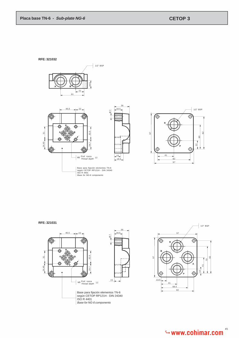
45
82
97
41
22
31
Placa base TN-6 - Sub-plate NG-6
Prof. roscaThread depth
82
82
68,5
41
13,5
82
97
21
RFE: 321032
RFE: 321031
18
,5
61
1/2” BSP
32
,52
4,7
24
,45
40,5
M5 Prof. roscaThread depth
Base para fijación elementos TN-6según CETOP RP121H - DIN 24340ISO R 4401Base for NG-6 components
22
32
,5
31
24
,7
24
,45
40,5
M5
Base para fijación elementos TN-6según CETOP RP121H - DIN 24340ISO R 4401Base for NG-6 components
15
Ø 7
18,5
19,5
36
15
Ø 7
18,5
36
1/2” BSP
60
97
1/2” BSP
12
97
70
41
12
22
12
CETOP 3
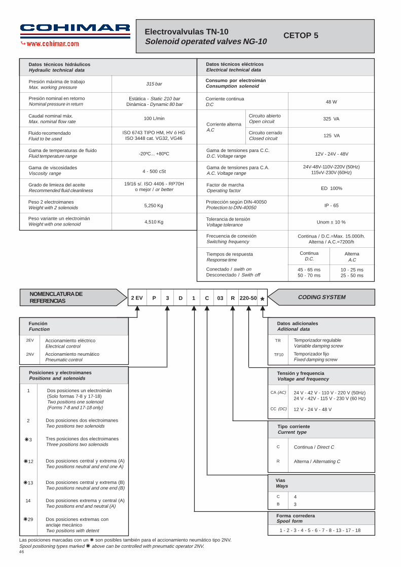
46
220-50
Electrovalvulas TN-10Solenoid operated valves NG-10
CETOP 5
Gama de temperaturas de fluidoFluid temperature range
Gama de viscosidadesViscosity range
Grado de limieza del aceiteRecommended fluid cleanliness
Peso 2 electroimanesWeight with 2 solenoids
Peso variante un electroimánWeight with one solenoid
12V - 24V - 48V
Unom ± 10 %
Datos técnicos hidráulicosHydraulic technical data
315 bar
Estàtica - Static 210 barDinàmica - Dynamic 80 bar
ISO 6743 TIPO HM, HV ó HGISO 3448 cat. VG32, VG46
-20ºC... +80ºC
4 - 500 cSt
19/16 s/. ISO 4406 - RP70Ho mejor / or better
5,250 Kg
4,510 Kg
Datos técnicos eléctricosElectrical technical data
Consumo por electroimánConsumption solenoid
Corriente continuaD.C 48 W
Corriente alternaA.C
325 VA
125 VA
Gama de tensiones para C.C.D.C. Voltage range
Gama de tensiones para C.A.A.C. Voltage range
Factor de marchaOperating factor
Tolerancia de tensiónVoltage tolerance
Protección según DIN-40050Protection to DIN-40050
Tiempos de respuestaResponse time
Frecuencia de conexiónSwitching frequency
Conectado / swith onDesconectado / Swith off
24V-48V-110V-220V (50Hz)115vV-230V (60Hz)
Continua / D.C.=Max. 15.000/h.Alterna / A.C.=7200/h
ContinuaD.C.
45 - 65 ms50 - 70 ms
10 - 25 ms25 - 50 ms
AlternaA.C
Presión máxima de trabajoMax. working pressure
Presión nominal en retornoNominal pressure in return
Caudal nominal máx.Max. nominal flow rate
Fluido recomendadoFluid to be used
ED 100%
IP - 65
100 L/min
*R03C1D3P2 EV CODING SYSTEMNOMENCLATURA DEREFERENCIAS
FunciónFunction
2EV
2NV
Accionamiento eléctricoElectrical control
Accionamiento neumáticoPneumatic control
Datos adicionalesAditional data
TR
TF10
Temporizador regulableVariable damping screw
Temporizador fijoFixed damping screw
Las posiciones marcadas con un � son posibles también para el accionamiento neumático tipo 2NV.Spool positioning types marked � above can be controlled with pneumatic operator 2NV.
ViasWays
Forma correderaSpool form
C
B
4
3
1 - 2 - 3 - 4 - 5 - 6 - 7 - 8 - 13 - 17 - 18
Tipo corrienteCurrent type
C
R
Continua / Direct C
Alterna / Alternating C
Tensión y frequenciaVoltage and frequency
CA (AC)
CC (DC)
24 V - 42 V - 110 V - 220 V (50Hz)24 V - 42V - 115 V - 230 V (60 Hz)
12 V - 24 V - 48 V
Posiciones y electroimanesPositions and solenoids
14 Dos posiciones extrema y central (A)Two positions end and neutral (A)
�13 Dos posiciones central y extrema (B)Two positions neutral and one end (B)
�12 Dos posiciones central y extrema (A)Two positions neutral and end one A)
�3 Tres posiciones dos electroimanesThree positions two solenoids
2 Dos posiciones dos electroimanesTwo positions two solenoids
1 Dos posiciones un electroimán(Solo formas 7-8 y 17-18)Two positions one solenoid(Forms 7-8 and 17-18 only)
�29 Dos posiciones extremas conanclaje mecánicoTwo positions with detent
Circuito abiertoOpen circuit
Circuito cerradoClosed circuit

47
* Solenoid current type:C for D.C. current, indicating after it voltage required.R for D.C. current, indicating after it voltage and frequency required.
1
2
3
4
5
6
13
2
2
4
7
8
17
18
* Tipo de corriente del electroimán:C para corriente continua, indicando a continuación la tensión deseada.R para corriente alterna, indicando a continuación la tensión y frequencia deseadas.
2EVP3D1C03*
2EVP3D2C03*
2EVP3D3C03*
2EVP3D4C03*
2EVP3D5C03*
2EVP3D6C03*
2EVP3D13C03*
2EVP2D2C03*
2EVP29D2C03*
2EVP12D4C03*
2EVP1D7B03*
2EVP1D8C03*
2EVP1D17B03*
2EVP1D18C03*
(1) Comunica. (2) Cerrado. (1) Connect. (2) Closed.
Para formas 7 y 8 el eletrcoimán estará situado en el lado de la toma «B»For forms 7 and 8 the solenoid will be placed at side of outlet «B»
P (1) A B y R (2)
P (1) A B (1) R
P (1) B A y R (2)
P (1) B A (1) R
P (1) B A y R (2)
P (1) B A (1) R
P (1) A B y R (2)
P (1) A B (1) R
Circulación de aceite - Connections
ReferenciaReference
Formade la
corredera Spoolform
SímboloSymbol
P (1) B A (1) RP (1) A B (1) R
P (1) A B (1) R
A y B (2) P (1) R
A y B (1) R P (2)
A (1) R B y P (2)
A (2) B y P (1) R
A y B (1) P R (2)
Solenoid conectadoSolenoid switched on
Solenoid desconectadoSolenoid switched off
Posición centralCentral position
P (1) B A (1) R
P Entrada de presiónPressure inlet port
A y B Tomas a cilindros omotoresOutlet ports to cylindersor motors
R Retorno a depósitoReturn to tank
A, B , P y R (2)
A, B y P (1) R
A, B, P (1) R
Solenoide Aconectado
Solenoid Aswitched on
Solenoide Bconectado
Solenoid Bswitched on
A B
Variante con un electroimán para formas 17 y 18Alternative with one solenoid for forms 17 and 18
1,6
21
,4
81
70
31
Ø 6,5
Ø 10,5
Ø 15,5
3,2
70
6,3
32
,5
107
16,7
24
37,3
54 24
50,8
274
61
21
2
102
252
7575
=
27
,5
44
Conexión electricaElectrical connection
Par aprieteFit torque
PG - 11
31
177
185
8
Ø 10,5
316
102
97 1
07
=
39
Variante sólo para corriente continuaD.C. Alternative only
14 - 16 Nm.

48
Junta tórica
Junta anti-extrusión
Arandela tope muelle
Aguja accionamiento
Cuerpo válvula piloto
Retén aceite
Arandela tope muelle
Embolo
Tapa toma aire
Junta tórica
Junta tórica
Arandela tope muelle
Muelle
1/8
”BS
P
O’ring
Antiextrusion gasket
Spring stop washer
Spring stop ring
Valve housing
Oil seal
Spring stop washer
Piston
Air inlet cover
O’ring
O’ring
Spring stop washer
Spring
Detalle accionamiento neumáticoPneumatic control details 2 NV
DenominaciónDescription
Núm.No.
Cant.Qty.
1 -2
1 -2
1 -2
1 -2
1 -2
1 -2
1 -2
1 -2
1 -2
1 -2
1 -2
1 -2
1 -2
Ø 27x1,5
Ø 4x2,5
1
2
3
4
5
6
7
8
9
10
11
12
13
Ø 3,4x1,9
La presión del pilotaje deberá estar comprendida entre 4 y 10 bar.The pilot pressure must be maintained between 4 and 10 bar.
Límites de funcionamientoOperation limits
Forma correderaSpool form
CurvaCurve
1 - 6
1 - 2 - 3 - 4 - 5 - 8 - 13 - 18
7 - 17
A
B
C
10 20 30 40 50 60 70 80 90 100
Q = L /min
P AForma correderaSpool form
1
2
3
4
5
6
13
7
8
17
18
B R P R
-
-
4
3
-
-
-
-
-
-
3
P A A R
6
8
8
9
6
9
8
5
5
5
8
6
8
8
9
6
9
8
4
4
4
8
5
5
5
2
5
-
3
-
3
5
2
7
7
7
1
7
-
4
-
4
7
1
P B
p =
bar
12
11
10
9
8
7
6
5
4
3
2
1
0
10 20 30 40 50 60 70 80
Q = L /min
p =
bar
315300
250
200
150
100
50
90 100 110
39
Ø 3
7
Par aprieteFit torque
2 m.Kg
DiagramaDiagram p-Q a 23 cSt.
1 2 3 4
5678
9

49
Muelle recuperación correderaSpool return spring
Bolas
Tornillo estrangulador fijo
Tuerca
Junta
Sumplemento muelle
Tope muelle
Tornillo estrangulador regulable
Tope corredera
Conjunto cuerpo y corredera
Tornillos
Junta metal-buna
Aguja accionamiento
Junta tórica
Tope muelle
Tapón corredera
Conjunto cuerpo y corredera
Anclajes acc.29
Muelle circular
Enchufe electroimán lado «A»
Enchufe electroimán lado «B»
Nucleo electroimán
Tuerca
Junta tórica
Bobina
Junta tórica
Junta tórica
Muelle recuperación corredora
Tapa
Balls
Screw
Nut
Gasket
Spring guide
Spring guide
Variable damping screw
Spool stop
Body and spool
Screws
Metal bonded gasket
Spring stop pin
O’ring
Spring guide
Spool plug
Body and spool
Detent
Spring
Solenoid connector
Solenoid connector
Solenoid core
Nut
O’ring
Coll
O’ring
O’ring
Spool return spring
Cover
Placa base individual
Tornillos para fijación
Sub-plate
Screws for fixing
Accesorios Requieren pedido por separadoAccesories That need separate orders
RFE. 140001 - 140002 - 332003 - 332004
Par de aprieteFit torque
DIN - 84 M6 x25
Ø 2,5
Núm.No.
1
2
3
4
5
6
7
8
9
10
DenominaciónDescription
Cant.Qty.
1
1
1 - 2
1 - 2
1 - 2
1 - 2
1 - 2
2
1 - 2
1
Ø 25x3,5
Ø 25,5x3
Ø 24x2,5
Núm.No.
11
12
13
14
15
16
17
18
19
20
DenominaciónDescription
Cant.Qty.
1
1
1
1 - 2
5
1 - 2
1
1
1
1
Núm.No.
21
22
23
24
25
26
27
28
DenominaciónDescription
Cant.Qty.
4
1
1
1
1
1
1
2
Núm.No.
DenominaciónDescription
Cant.Qty.
DIN - 912 M6 x 40 14 -16 Nm.
Con la instalación de los tornillos marcas 22 y 27(Tornillos estranguladores) permite graduar la velocidadde desplazamiento de la corredera.Al efectuar dichaoperación, comprobar que el canal de comunicaciónesté lleno de aceite, ya que de lo contrario, el reglajedel tiempo de conexión no se podria realizar.
The speed of the spool movement can be adjusted, byreplacing screw plug by a thorttle screw no. 22 or 27.Take care that the complete volume of oil is maintainedin the duct connector, since this is essential for operationof the damping adjustment.
Utilizable solamente con electroimánes de C.C.Only for use with D.C. solenoid
AccionamientoPositioning device 14Accionamiento
Positioning device 3AccionamientoPositioning device 1
AccionamientoPositioning device
29
Ejemplo para pedido de recambiosExample to order spare parts
CantidadQuantity
DenominaciónDescription
N.º de la piezaPart number
Referencia según la placaReference according serial number plate
2 9Para válvulaFor valve 2EVP3D2C03R220-50
Ø 12x2
AccionamientoPositioning device 2
AccionamientoPositioning device 12
AccionamientoPositioning device 13
T R
TF10
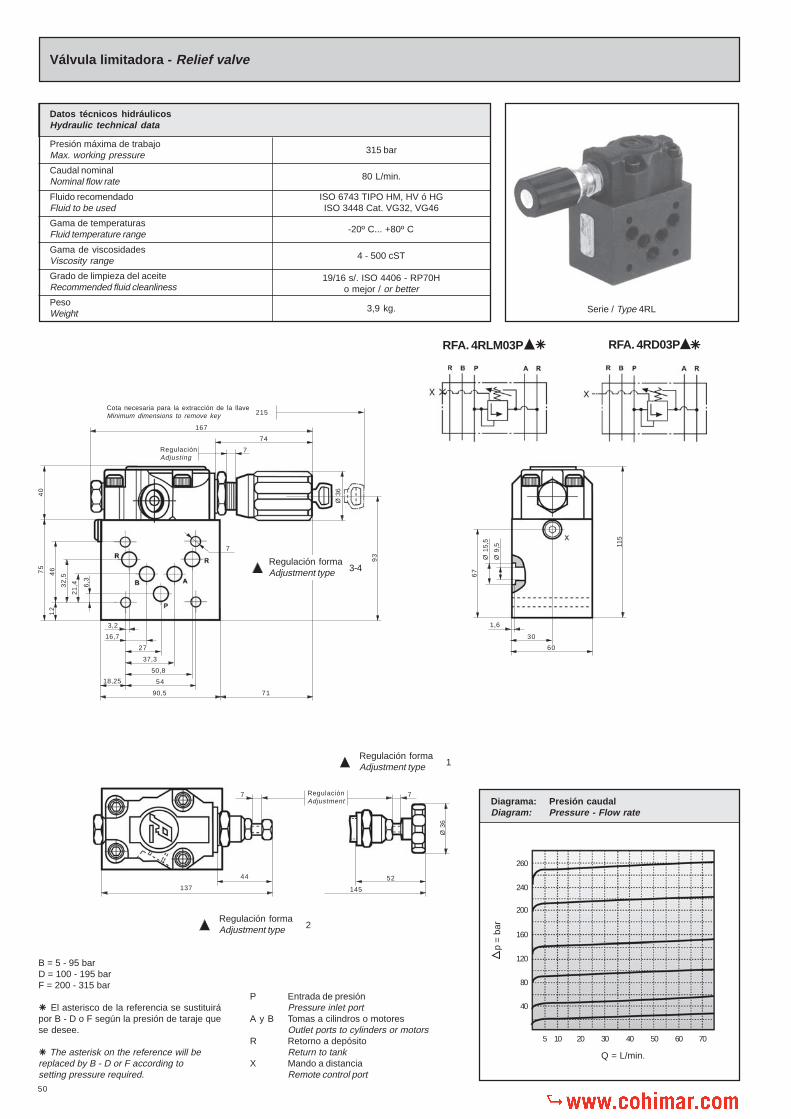
50
B = 5 - 95 barD = 100 - 195 barF = 200 - 315 bar
El asterisco de la referencia se sustituirápor B - D o F según la presión de taraje quese desee.
The asterisk on the reference will bereplaced by B - D or F according tosetting pressure required.
�
�
P Entrada de presiónPressure inlet port
A y B Tomas a cilindros o motoresOutlet ports to cylinders or motors
R Retorno a depósitoReturn to tank
X Mando a distanciaRemote control port
Ø 3
6
167
74
7
40
71
3,2
16,7
27
37,3
50,8
54
90,5
18,25
32
,5
12
6,3
21
,4
4675
145
93
RFA. 4RD03P �
RegulaciónAdjusting
Cota necesaria para la extracción de la llaveMinimum dimensions to remove key
Ø 9
,5
Ø 1
5,5
1,6
30
60
7 7
44
137
52
7
67
115
�RFA. 4RLM03P
p =
bar
40
80
120
160
200
240
260
5 10 20 30 40 50 60 70
Q = L/min.
Diagrama: Presión caudalDiagram: Pressure - Flow rate
Ø 3
6
Datos técnicos hidráulicosHydraulic technical data
Presión máxima de trabajoMax. working pressure
Caudal nominalNominal flow rate
Fluido recomendadoFluid to be used
Gama de temperaturasFluid temperature range
Gama de viscosidadesViscosity range
Grado de limpieza del aceiteRecommended fluid cleanliness
PesoWeight
315 bar
80 L/min.
ISO 6743 TIPO HM, HV ó HGISO 3448 Cat. VG32, VG46
-20º C... +80º C
4 - 500 cST
19/16 s/. ISO 4406 - RP70Ho mejor / or better
3,9 kg.
Válvula limitadora - Relief valve
215
RegulaciónAdjustment
Serie / Type 4RL
Regulación formaAdjustment type 2
Regulación formaAdjustment type 1
Regulación formaAdjustment type 3-4

51
Válvula limitadora - Relief valve
B = 5 - 95 barD = 100 - 195 barF = 200 - 315 bar
El asterisco de la referencia se sustituirápor B - D o F según la presión de taraje quese desee.
The asterisk on the reference will bereplaced by B - D or F according tosetting pressure required.
�P Entrada de presión
Pressure inlet portA y B Tomas a cilindros o motores
Outlet ports to cylinders or motorsR Retorno a depósito
Return to tankX Mando a distancia
Remote control port
Diagrama: Presión caudalDiagram: Pressure - Flow rate
p =
bar
40
80
120
160
200
240
260
5 10 20 30 40 50 60 70
Q = L/min.
Tipo de corriente del electroimán.5 C para corriente continua, indicando a continuación la tensión deseada.5 R para corriente alterna, indicando a continuación la tensión y frecuencia deseada. Solenoid current type5 C for D.C. current, indicating after it voltage required.5 R for A.C. current, indicating after it voltage and frequency required.
RFA. 4RLM03P /�
Circuio abiertoOpen circuit
Circuito cerradoClosed circuit
Datos elèctricosElectrical date
Consumo electroimán C.A.Consumption per solenoid A.C.
Gama de tensiones C.C.Voltage range D.C.
Gama de tensiones C.A.Voltage range D.A.
Factor de marchaOperating factor
Protección segúnProtection according
30 W.
180 VA
12 - 24 V.
24 - 48 - 110 - 220 V (50 Hz)115 - 230 V (60 Hz)
ED 100 %
IP - 65DIN - 40050
65 VA
Datos técnicos hidráulicosHydraulic technical data
Presión máxima de trabajoMax. working pressure
Caudal nominalNominal flow rate
Fluido recomendadoFluid to be used
Gama de temperaturas del fluidoFluid temperature range
Gama de viscosidadesViscosity range
Grado de limpiezaRecommended fluid cleanliness
PesoWeight
315 bar
80 L/min.
ISO 6743 TIPO HM, HV ó HGISO 3448 Cat. VG32, VG46
-20º C... +80º C
4 - 500 cST
19/16 s/. ISO 4406 - RP70Ho mejor / or better
1,2 kg.
54
71
3,2
16,7
27
37,3
50,8
90,5
18,25
32
,5
12
6,3
21
,4
4675
7
155 C.A. (A.C.)170 C.C. (D.C.)
Ø 3
6
93
Cota necesaria para la extracción de la llaveMinimum dimensions to remove key + 50
60
67
1,6
30
Ø 9
,5
Ø 1
5,5
13
6
19
7
44
Ø 3
6
RegulaciónAdjustment
7 7
52
13
Consumo electroimán C.C.Consumption per solenoid D.C.
RFA. 4RD03P /�Regulación formaAdjustment type 2
Regulación formaAdjustment type 1

52
Junta metal-buna
Tapón
Tapón cónico
Junta tórica
Junta antiextrusión
Tornillo regulación paso aceite
Junta tórica
Guía válvula descarga
Muelle válvula descarga
Válvula descarga
Cuerpo válvula
Tapón
Tornillos
Tuerca especial
Juntas tóricas
Cuerpo válvula piloto
Ø 22,5x2
Ø 20x1,5
DIN-912 M8x40
Ø 12,4x1,78
Elastic pin
Nut
Knob adapter
O’ring
Spring for
Spring for
Spring for
Relief valve
Valve seat
Actuating part
O’ring
Guide for relief valve
Guide for relief valve
Metal bonded gasket
Plug
O’ring
Cerradura
Guía volante
Guía volante
Bolas
Pasador
Muelle
Tapón tope bolas
Volante
Adaptador volante
Junta metal-buna
Volante
Suplemento volante
Pasador
Junta tórica
Tornillo regulación
Volante regulación
Locking system
Knob guide
Knob fixing pin
Balls
Elastic pin
Spring
Plug
Knob
Knob adaptor
Metal bonded gasket
Knob
Knob cover
Elastic pin
O’ring
Adjusting screw
Knob
Núm.No.
1
2
3
4
5
6
7
8
9
10
11
12
13
14
15
16
DenominaciónDescription
Cant.Qty.
1
1
1
30
2
1
1
1
1
1
1
1
1
1
1
1
DIN-1481 Ø 2x20
Ø 3x18
Ø 16,9x2,7
Núm.No.
17
18
19
20
21
22
23
24
25
26
27
28
29
30
31
32
DenominaciónDescription
Cant.Qty.
1
1
1
1
1
1
1
1
1
1
1
1
1
1
1
2
Pasador
Tuerca
Adaptador volante
Junta tórica
Muelle para
Muelle para
Muelle para
Válvula limitadora
Anillo cierre
Embolo accionador
Junta tórica
Guía para vál. descarga en vacío
Guía para vál. limitadora
Junta metal-buna
Tapón cuerpo válvula
Junta tórica
Ø 3x12
Ø 8,9x1,9
5 - 95 bar
100 - 195 bar
200 - 315 bar
Ø 10x2
Ø 7,2x1,9
Metal bonded gasket
Plug
Plug
Plug
Antiextrusion gasket
Oil throttling screw
O’ring
Poppet guide and seat
Spring
Poppet
Valve housing
Plug
Screws
Nut
O’ring
Pilot valve housing
Núm.No.
33
34
35
36
37
38
39
40
41
42
43
44
45
46
47
48
DenominaciónDescription
Cant.Qty.
1
1
1
2
1
1
1
1
1
1
1
1
4
1
5
1
Para válvula limitadora suprimir las piezas marcas 26,27 y 28 y montar la pieza marca 29.For relief valve dispense with parts Nos. 26, 27 and 28and include part No. 29.
Para válvula de descarga en vacío suprimir las piezasmarcas 33 y 34.For unloading valve dispense with parts No. 33 and 34.
Ejemplo para pedido de recambiosExample to order spare parts
CantidadQuantity
DenominaciónDescription
N.º de la piezaPart number
Referencia según la placaReference according serial number plate
1MuelleSpring 41
Para válvulaFor valve 4RLM03P2B
Accesorios Requieren pedido por separadoAccessories That need separate orders
Sub-plate
Top cover
O’rings for individual mounting
Screws for fixing
Placa base individual
Tapa superior
Juntas tóricas para montaje individual
Tornillos para fijación
RFE. 140001 - 140002 - 332003 - 332004
RFE. 5928004
Ø 24 x 2 (2) Ø 12,4 x 1,78 (1)
DIN - 912 M6 x 80 (4) 14 - 16 Nm.Par de aprieteFit torque

53
Válvula de sobrepresión simple - Simple relief valve
Serie / Type 1RLS
RFA: 1RLS03P2 /B�
Diagrama: Presión caudalDiagram: Pressure - Flow rate
5 10 20 30 40 50 60 70
Q = L/min.
40
80
120
160
200
240
p =
bar
Diagrama:Diagram: p-Q a 23 cST.
5 10 20 30 40 50 60 70
Q = L/min.
2
4
6
8
10
12
14
16
18
p =
bar
Datos técnicos hidráulicosHydraulic technical data
Presión máxima de trabajoMax. working pressure
Caudal nominalNominal flow rate
Fluido recomendadoFluid to be used
Gama de temperaturasFluid temperature range
Gama de viscosidadesViscosity range
Grado de limpieza del aceiteRecommended fluid cleanliness
PesoWeight
315 bar
80 L/min.
ISO 6743 TIPO HM, HV ó HGISO 3448 Cat. VG32, VG46
-20º C... +80º C
4 - 500 cST
19/16 s/. ISO 4406 - RP70Ho mejor / or better
2,250 kg.
==
45
61
16
1,3Ø 9
Ø 16
Tapa superiorTop cover
La tapa ref. 5928017 se incluye en el suministro de la válvula.Plate ref. 5928017 is provided with the valve
16,75
18,25 54 18,25
50,75
37,25
27
3,25
85
= =
90,5
175,5
12
,25
12
,25
463
2,52
1
6
70
,5
==
6,5
RFA: 1RLS03P2 /A�Invertir posición de la placa 5928017Invert position of plate 5928017
P Entrada de presiónPressure inlet port
A y B Tomas a cilindros o motoresOutlet ports to cylinders or motors
R Retorno a depósitoReturn to tank
B = 5 - 80 barD = 85 - 175 barF = 180 - 315 bar
�El asterísco de la referencia se sustituirápor B - D - F o G según la presión de taraje quese desee.�The asterisk in the part number will bereplaced by B - D - F or G according tosetting pressure required.
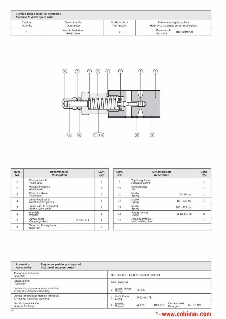
54
RFE. 140001 - 140002 - 332003 - 332004
RFE. 5928004
2 Ø 24x2
1 Ø 12,4x1,78
4 M6x70 DIN-912 14 - 16 Nm.
Placa base individual
Tapa superior
Juntas tóricas para montaje individual
Juntas tóricas para montaje individual
Tornillos para fijación
Ejemplo para pedido de recambiosExample to order spare parts
CantidadQuantity
DenominaciónDescription
N.º de la piezaPart number
Referencia según la placaReference according serial number plate
1Válvula limitadora
Relief valve 2Para válvulaFor valve 1RLS03P2D/B
Adjusting screw
Nut
Spring
Spring
Spring
O’ring
Intermediate plate
Tapón regulación
Contratuerca
Muelle
Muelle
Muelle
Juntas tóricas
Placa intermedia
Núm.No.
9
10
11
12
13
14
15
DenominaciónDescription
Cant.Qty.
1
1
1
1
1
5
1
5 - 80 bar
85 - 175 bar
180 - 315 bar
Ø 12,4x1,78
Valve body
Relief valve
Valve head
Metal bonded gasket
Safety valve cover
Washer
Copper gaskets
Blind nut
Cuerpo válvula
Volante limitadora
Cabeza válvula
Junta metal-buna
Tapón válvula seguridad
Arandela
Juntas cobre
Tapón tornillo regulación
Núm.No.
1
2
3
4
5
6
7
8
DenominaciónDescription
Cant.Qty.
1
1
1
1
1
1
2
1
Ø 10x14x1
Juntas tóricas
Junta tórica
Tornillos
O’rings
O’ring
Screws
Accesorios Requieren pedido por separadoAccessories That need separate orders
Sub-plate
Top cover
O’rings for individual mounting
O’rings for individual mounting
Screws for fixingPar de aprieteFit torque

55
Serie / Type 1RLD
RFE: 1RLD03P2 /� �
Diagrama: Presión caudalDiagram: Pressure - Flow rate
Q = L/min.
40
80
120
160
200
240
280
5 10 20 30 40 50 60 70
p =
bar
Diagrama:Diagram: p-Q a 23 cST.
5 10 20 30 40 50 60 70
Q = L/min.
2
4
6
8
10
12
14
16
18
p =
bar
Datos técnicos hidráulicosHydraulic technical data
Presión máxima de trabajoMax. working pressure
Caudal nominalNominal flow rate
Fluido recomendadoFluid to be used
Gama de temperaturasFluid temperature range
Gama de viscosidadesViscosity range
Grado de limpieza del aceiteRecommended fluid cleanliness
PesoWeight
315 bar
80 L/min.
ISO 6743 TIPO HM, HV ó HGISO 3448 Cat. VG32, VG46
-20º C... +80º C
4 - 500 cST
19/16 s/. ISO 4406 - RP70Ho mejor / or better
2,350 kg.
Válvula de sobrepresión doble - Double relief valve
195,5
90,5
18,25 18,2554
3,25
16,75
27
37,25
50,75
463
2,52
1
6
12,2
512
,25= =
52,5 52,5
==
70
,5
Tapa superiorTop cover
16
,53
3,5
16
,53
3,5
50
66
16
Ø 8
Ø 16
1,3
6,5
P Entrada de presiónPressure inlet port
A y B Tomas a cilindros o motoresOutlet ports to cylinders or motors
R Retorno a depósitoReturn to tank
B = 5 - 80 barD = 85 - 175 barF = 180 - 315 bar
�El asterísco de la referencia se sustituirápor B - D o F según la presión de taraje que sedesee.�The asterisk in the part number will bereplaced by B - D or F according tosetting pressure required.

56
RFE. 140001 - 140002 - 332003 - 332004
RFE. 5928004
2 Ø 24x2
1 Ø 12,4x1,78
4 M6x75 DIN-912 14 - 16 Nm.
Blind nut
Adjusting screw
Nut
Copper gasket
Safety valve cover
Metal bonded gasket
Washer
Tapón tornillo regulación
Tornillo regulación
Contratuerca
Juntas cobre
Tapón válvula seguridad
Junta metal-buna
Arandela
Núm.No.
1
2
3
4
5
6
7
DenominaciónDescription
Cant.Qty.
2
2
2
4
2
2
1
Ø 8,5x12x1
Spring
Spring
Spring
O’rings
Relief valve
Valve head
Valve body
Muelle
Muelle
Muelle
Juntas tóricas
Válvula limitadora
Cabeza válvula
Cuerpo válvula
Núm.No.
8
9
10
11
12
13
14
DenominaciónDescription
Cant.Qty.
2
2
2
5
2
2
1
5 - 80 bar
85 - 175 bar
180 - 315 bar
Ø 12,4x1,78
Juntas tóricas
Junta tórica
Tornillos
O’rings
O’ring
Screws
Accesorios Requieren pedido por separadoAccessories That need separate orders
Sub-plate
Top cover
O’rings for individual mounting
O’rings for individual mounting
Screws for fixing
Placa base individual
Tapa superior
Juntas tóricas para montaje individual
Juntas tóricas para montaje individual
Tornillos para fijación Par de aprieteFit torque
Ejemplo para pedido de recambiosExample to order spare parts
CantidadQuantity
DenominaciónDescription
N.º de la piezaPart number
Referencia según la placaReference according serial number plate
1Cuerpo válvula
Valve body 14Para válvulaFor valve 1RLD03P2D/B
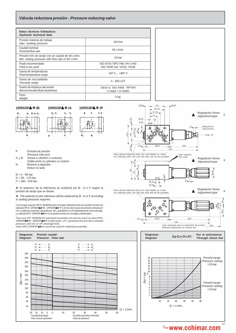
57
76
Regulación formaAdjustment type 2
1RR03P /B� 1RR03P /A� 1RR03P /P�
Con la tapa superior RFA: 5928004 para montaje individual slolo se podrán montar lasválvulas RFA: 1RR03P /B - 1RR03P /P y en los dos casos de presión entrará por«P» y saliendo a presión reducida por «B», quedando A o R indistintamente como dranaje.La válvula RFA: 1RR03P /A no se podrá montar en montajes individuales.
Top cover RF: 5928004 for individual assembly can only be used on valve RFE:1RR03P /B - 1RR03P /P in both cases, «P», is pressure line 2nd «B» is reducedpressure, and «A» or «R» drainage lines.Valve RFE:1RR03P /A cannot be used for individual assembly.
� �
�
� �
�
P Entrada de presiónPressure inlet port
A y B Tomas a cilindros o motoresOutlet ports to cylinders or motors
R Retorno a depósitoReturn to tank
B = 5 - 80 barD = 85 - 175 barF = 180 - 315 bar
El asterisco de la referencia se sustituirá por B - D o F según lapresión de taraje que se desee.
The asterisk on the reference will be replaced by B - D or F accordingto setting pressure required.
�
�
Diagrama:Diagram:
Por el antirretornoThrough check linep-Q a 23 cST.
Válvula reductora presión - Pressure reducing valve
Datos técnicos hidráulicosHydraulic technical data
Presión máxima de trabajoMax. working pressure
Caudal nominalNominal flow rate
Fluido recomendadoFluid to be used
Gama de temperaturasFluid temperature range
Gama de viscosidadesViscosity range
Grado de limpieza del aceiteRecommended fluid cleanliness
PesoWeight
315 bar
60 L/min.
ISO 6743 TIPO HM, HV ó HGISO 3448 Cat. VG32, VG46
-20º C... +80º C
4 - 500 cST
19/16 s/. ISO 4406 - RP70Ho mejor / or better
3 kg.
Presión mín de taraje con un caudal de 60 L/min.Min. setting pressure with flow rate of 60 L/min. 10 bar
Diagrama: Presión caudalDiagram: Pressure - Flow rate
R A1
R B1
R P1
A A1
B B1
P P1
p =
bar
Caudal descargaFlow shock absorber
20
40
60
100
120
140
160
5 0 10 20 30 40 50 60101520
180
200
220
240
80
260
Caudal a presión reducidaFlow at reduced
Q = L/min.
24
Para válvula reductora toma «B» este taladro no existeFor reducing valve «B» port this bore will not be provided
106
5418,25 18,25
50,75
37,25
27
16,75
3,25
10 RegulaciónAdjustment
201
7
70
,5
46 32
,5 21
6
12
,25
12
,25
5,5
28
52
16
68
Ø 10
Ø 16
Exg. 13
13
10
Ø 3
6
Cota necesaria para la extracción de la llaveMinimum dimensions to remove key
90,5 136
232
5,5
282
Para válvula reductora toma «A» este taladro no existeFor reducing valve «A» port this hole will not be provided
36
,53
4
Tapa superiorTop cover
90,5
Regulación formaAdjustment type 3
Regulación formaAdjustment type 4
Presión tarajePressure setting
<10 bar
10 20 30 40 50 60
Q = L/min.
12345
89101112131415
Presión tarajePressure setting
<10 bar
p =
bar

58
Tapón bolas
Volante
Junta tórica
Pasador elástico
Suplemento volante
Volante
Muelle
Tapón
Junta tórica
Pasador
Válvula retención
Tapón
Tapón
NOTA: Para taraje «B» se montará el muelle núm. 6Para taraje «D» se montarán los muelles núms. 6-7Para taraje «F» se montarán los muelles núms. 6-8
NOTE: For pressure setting «B» range spring No. 6 will be assembliedFor pressure setting «D» range springs Nos. 6-7 will be assembledFor pressure setting «F» range springs Nos. 6-8 will be assembled
Vál. Reductora tomas B-P: Para presiones inferiores a 32 bar. se suprimirá el pistónnúm. 3 y se montará el tapón núm. 39.
Reducing valve ports B-P: For pressures under 32 bar. piston no. 3 will be removedand plug no. 39 will be fitted.
Vál. Reductora toma A: Para presiones inferiores a 32 bar. se suprimirá el pistónnúm. 3 y se montará el tapón núm. 38.
Reducing valve port A: For pressures under 32 bar. piston no. 3 will be removedand plug no. 38 will be fitted.
Detalle válvula retención sólopara reductora en toma A ó B.
Check valve detail only forreducing valve in port A or B.
Ejemplo para pedido de recambiosExample to order spare parts
CantidadQuantity
DenominaciónDescription
N.º de la piezaPart number
Referencia según la placaReference according serial number plate
1Adaptador volante
Knob adaptor 20Para válvulaFor valve 1RR02P2D/P
Sub-plate
Top cover
O’rings for individual mounting
O’rings for individual mounting
Screws for fixing
Placa base individual
Tapa superior
Juntas tóricas para montaje individual
Juntas tóricas para montaje individual
Tornillos para fijación
Accesorios Requieren pedido por separadoAccessories That need separate orders
RFE. 140001 - 140002 - 332003 - 332004
RFE. 5928004
2 Ø 24 x 2
1 Ø 12,4 x 1,78
4 M6 x 70 DIN-912 14 - 16 Nm.Par de aprieteFit torque
O’rings
O’ring
Screws
Juntas tóricas
Junta tórica
Tornillos
Plug
Knob
O’ring
Elastic pin
Knob cover
Knob
Spring
Plug
O’ring
Pin
Check valve
Plug
Plug
Nut
O’ring
Spring guide
Spool plug
Screws
O’ring
Knob adaptor
Balls
Knob fixing pin
Knob guide
Locking system
Elastic pin
Spring
Metal bonded gasket
Plug
Piston
Spool
Spring guide
Spring for
Spring for
Spring for
Metal bonded gasket
Knob adaptor
Adjusting screw
Elastic pin
Nut
Junta metal-buna
Tapón tope corredera
Embolo de pilotaje
Corredera
Guía muelle
Muelle para
Muelle para
Muelle para
Junta metal-buna
Adaptador volante
Tornillo regulación
Pasador elástico
Tuerca
Núm.No.
1
2
3
4
5
6
7
8
9
10
11
12
13
DenominaciónDescription
Cant.Qty.
1
1
1
1
1
1
1
1
1
1
1
1
1
5 - 80 bar
85 -175 bar
180 - 315 bar
Ø 3x12
Contratuerca
Junta tórica
Guía muelle
Tapón corredera
Tornillos
Juntas tóricas
Adaptador volante
Bolas
Guía volante
Guía volante
Cerradura
Pasador elástico
Muelle
Núm.No.
14
15
16
17
18
19
20
21
22
23
24
25
26
DenominaciónDescription
Cant.Qty.
1
1
1
4
5
1
1
1
1
1
2
1
1
Ø 8,9x1,9
DIN-912 M5X16
Ø 12,4x1,78
Ø 2x20
Núm.No.
27
28
29
30
31
32
33
34
35
36
37
38
39
DenominaciónDescription
Cant.Qty.
1
1
2
1
2
1
1
1
1
1
1
Ø 16,9x2,7
Ø 3x18
Ø 8x16
Ø 2x10

59
12,5
79,5
12,5
40
36
Placa base con válvula limitadora - Sub-plate with relief valve
Datos técnicos hidráulicosHydraulic technical data
Presión máxima de trabajoMax. working pressure
Caudal nominalNominal flow rate
Fluido recomendadoFluid to be used
Gama de temperaturasFluid temperature range
Gama de viscosidadesViscosity range
Grado de limpieza del aceiteRecommended fluid cleanliness
PesoWeight
315 bar
80 L/min.
ISO 6743 TIPO HM, HV ó HGISO 3448 Cat. VG32, VG46
-20º C... +80º C
4 - 500 cST
19/16 s/. ISO 4406 - RP70Ho mejor / or better
4,84 kg.
ReferenciaReference
R(BSP)
Prof. roscaThread depth
4RLM03P2 /04
4RLM03P2 /06
�
�
1/2”
3/4”
15
17
P Entrada de presiónPressure inlet port
A y B Tomas a cilindros o motoresOutlet ports to cylinders or motors
R Retorno a depósitoReturn to tank
B = 5 - 95 barD = 100 - 195 barF = 200 - 315 bar
El asterisco de la referencia se sustituirápor B - D o F según la presión de taraje quese desee.
The asterisk on the reference will bereplaced by B - D or F according tosetting pressure required.
Nota: Para diagrama presión-caudal ver gráfico pág. 53Note: For diagram pressure-flow, see curves pag. 53
�
�
108,5
33
40
75
4,5
R
60
44,5
40 3
3
79
,4
40
92
R
ReferenciaReference
R(BSP)
Prof. roscaThread depth
4RLL03P2 /04
4RLL03P2 /06
�
�
1/2”
3/4”
15
17
28
115
12
0
Base para fijación elementos T-10según CETOP RP121H - DIN 24340ISO R 4401Base for NG-10 components
79,5
47,5
75
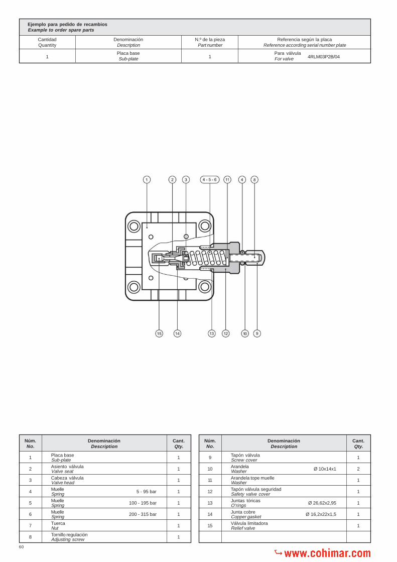
60
Ejemplo para pedido de recambiosExample to order spare parts
CantidadQuantity
DenominaciónDescription
N.º de la piezaPart number
Referencia según la placaReference according serial number plate
1Placa baseSub-plate 1
Para válvulaFor valve 4RLM03P2B/04
1
2
3
4
5
6
7
8
Placa base
Asiento válvula
Cabeza válvula
Muelle
Muelle
Muelle
Tuerca
Tornillo regulación
Sub-plate
Valve seat
Valve head
Spring
Spring
Spring
Nut
Adjusting screw
Núm.No.
DenominaciónDescription
Cant.Qty.
1
1
1
1
1
1
1
1
5 - 95 bar
100 - 195 bar
200 - 315 bar
9
10
11
12
13
14
15
Núm.No.
DenominaciónDescription
Cant.Qty.
1
2
1
1
1
1
1
Tapón válvula
Arandela
Arandela tope muelle
Tapón válvula seguridad
Juntas tóricas
Junta cobre
Válvula limitadora
Screw cover
Washer
Washer
Safety valve cover
O’rings
Copper gasket
Relief valve
Ø 10x14x1
Ø 26,62x2,95
Ø 16,2x22x1,5

61
Placas base múltiples TN-10CETOP 5 Manifold blocks NG-10
35
,65
32
M6 rosca útil 13M6 useful thred 13
21
,4
33
23
100
10
24
65
90
65
53
10
18
6,5 5
96
A
113
B
80
80
46
32
,5
6,3
3,2
16,7
27
37,3
5419
Ø 6,5
10
24
65
90
63 5
3
10
18
3/4” BSP 1/2” BSP
80
37
,5
37
,5
38,5
63
1/2” BSP
3/4” BSP 1/2” BSP
2 Tal a M8 rosca útil 122 Holes M8 useful thread 12
2 Tal a M8 rosca útil 122 Holes M8 useful thread 12
Nº MódulosNo. of
elements
ReferenciaReference A B
2 M859802 174 -
3 M859803 254 80
4 M859804 334 160
5 M859805 414 240
6 M859806 494 160+160

62
Datos técnicos hidráulicosHydraulic technical data
Presión máxima de trabajoMax. working pressure
Caudal nominal máx.Max. nominal flow rate
Fluido recomendadoFluid to be used
Gama de temperaturasFluid temperature range
Gama de viscosidadesViscosity range
Grado de limpieza del aceiteRecommended fluid cleanliness
315 bar
80 L/min.
ISO 6743 TIPO HM, HV ó HGISO 3448 Cat. VG32, VG46
-20º C... +80º C
4 - 500 cST
19/16 s/. ISO 4406 - RP70Ho mejor / or better
Placa base múltiple TN-10 tomas lateralesManifold blocks NG-10
Presión máxima en retornoMax. return line pressure 80 bar
CETOP 5
43
65
B
32
19
14
66
13
0
39
63
110
10
10
56
3/4” BSP
M8
21
67
9
Ø 9
28
96
A
78
1/2” BSP
3/8” BSP
Ø9
10
72
46
463
2,5
21
,4
6,3
32 54
37,3
27
16,7
3,2
89
69
86
56
162
28 63
3/4” BSP
Sustituir por el tarajeReplace with pressure
00 = sín válvula / without valve11 = 5 - 80 bar12 = 80 - 175 bar13 = 175 - 250 bar
Sustituir por la tensión del electroimánReplace with solenoid’s voltage
12 = 12V C.C./D.C.24 = 24V C.C./D.C.
1B1LV03 - / 1 145 125
1B2LV03 - / 2 225 205
1B3LV03 - / 3 305 285
1B4LV03 - / 4 380 360
1B5LV03 - / 5 460 440
1B6LV03 - / 6 540 520
RFA. ROQUETNº. ElementosNo. Elements A B
Diagrama válvula by-passCurves for by-pass valve
10 20 30 40 50 60 70 80
2
4
6
10
8
90 100
Q = L /min
P R
P =
bar

63
Válvula de retención simple - Check valve
Serie / Type 1VRS
RFE: 1VRS03P�
Datos técnicos hidráulicosHydraulic technical data
Presión máxima de trabajoMax. working pressure
Caudal nominalNominal flow rate
Fluido recomendadoFluid to be used
Gama de temperaturasFluid temperature range
Gama de viscosidadesViscosity range
Grado de limpieza del aceiteRecommended fluid cleanliness
PesoWeight
315 bar
80 L/min.
ISO 6743 TIPO HM, HV ó HGISO 3448 Cat. VG32, VG46
-20º C... +80º C
4 - 500 cST
19/16 s/. ISO 4406 - RP70Ho mejor / or better
2 kg.
18,25
3,25
16,75
27
37,25
50,75
18,2554
6 21
32
,5
46
70
,5
12
,25
12
,25
= =
90,5
48
1,3 Ø 10
Ø 16
NOTA:El asterisco de la referencia se sustituirá por un «1» si se deseaque la presión de apertura sea de 0,5-1 bar y por un «2» si ha deser de 2-3 bar.
NOTE:The reference asterisk will be replaced by number «1» whenwanted opening pressure is 0,5-1 bar and by number «2» if 2-3bar is wanted
p =
bar
1
2
3
5
6
7
8
10010 20 30 40 50 60 908070
9
4
Q = L/min.
Diagrama:Diagram: p-Q a 23 cST.
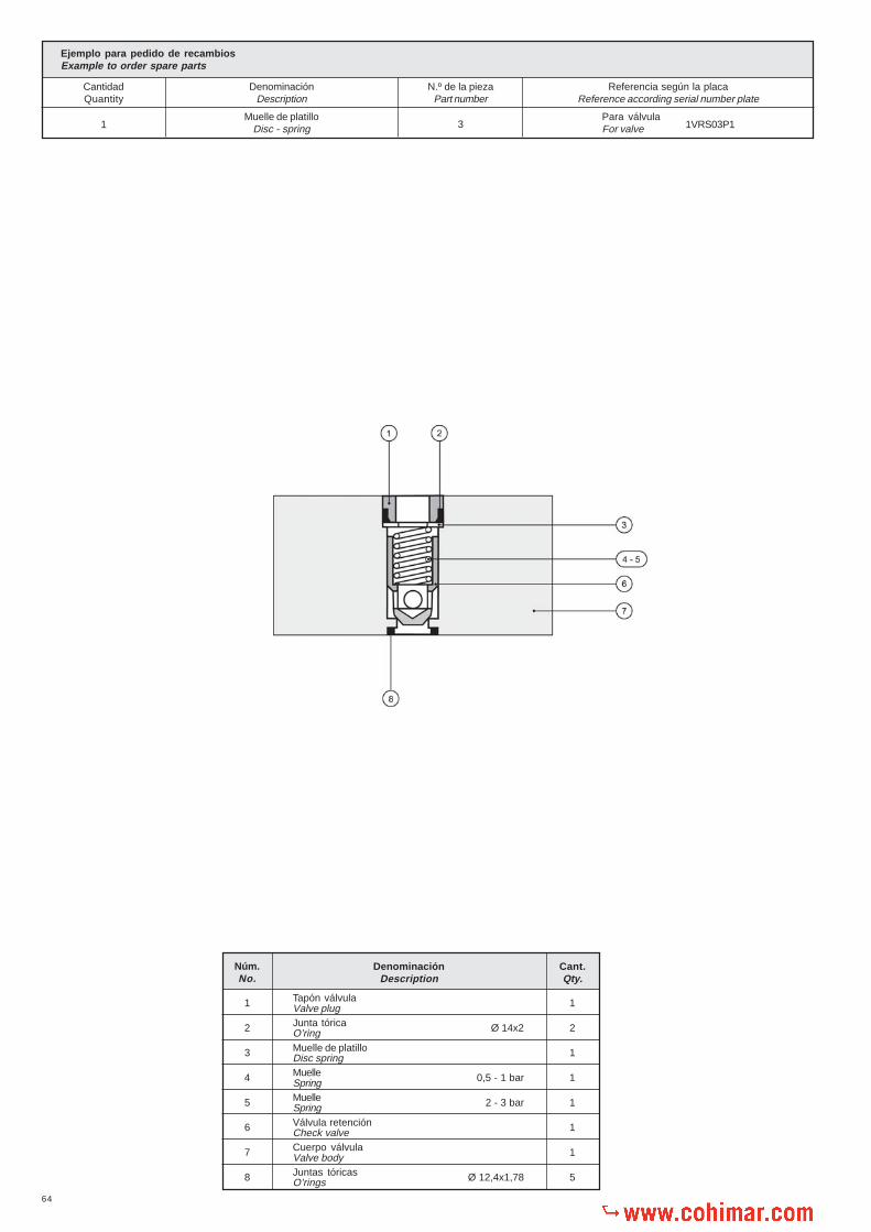
64
Ejemplo para pedido de recambiosExample to order spare parts
CantidadQuantity
DenominaciónDescription
N.º de la piezaPart number
Referencia según la placaReference according serial number plate
1Muelle de platillo
Disc - spring 3Para válvulaFor valve 1VRS03P1
1
2
3
4
5
6
7
8
Tapón válvula
Junta tórica
Muelle de platillo
Muelle
Muelle
Válvula retención
Cuerpo válvula
Juntas tóricas
Valve plug
O’ring
Disc spring
Spring
Spring
Check valve
Valve body
O’rings
Núm.No.
DenominaciónDescription
Cant.Qty.
1
2
1
1
1
1
1
5
Ø 14x2
0,5 - 1 bar
2 - 3 bar
Ø 12,4x1,78

65
Serie / Type 1VRH
Válvula de retención pilotada - Pilot check valve
Datos técnicos hidráulicosHydraulic technical data
Presión máxima de trabajoMax. working pressure
Caudal nominalNominal flow rate
Fluido recomendadoFluid to be used
Gama de temperaturasFluid temperature range
Gama de viscosidadesViscosity range
Grado de limpieza del aceiteRecommended fluid cleanliness
PesoWeight
315 bar
80 L/min.
ISO 6743 TIPO HM, HV ó HGISO 3448 Cat. VG32, VG46
-20º C... +80º C
4 - 500 cST
19/16 s/. ISO 4406 - RP70Ho mejor / or better
2,350 kg.
Relación aperturaOpening ratio
2,4:1
Relación decompresiónDecompression ratio
15:1
RFE. 1VRHD03P1
RFE. 1VRHS03P1
P Entrada de presiónPressure inlet port
A y B Tomas a cilindros o motoresOutlet ports to cylinders or motors
R Retorno a depósitoReturn to tank La tapa ref. 5928017 se incluye en
el suministro de la válvula.Plate ref. 5928017 is provided withthe valve
Exag. 36
Diagrama:Diagram:
p =
bar
Q = L/min.
2
4
6
8
10
12
14
10 20 30 40 50 60 70
16
18
20
46 3
2,52
1
18,25
27
37,25
50,75
3,25
16,75
18,2554
6
= =
34 90,5 34
158,5
24
33
57
73
16
1,3Ø 10
Ø 16
Tapa superiorTop cover
142,5
18,5
70
,5
21
25
12
,51
2,5
p-Q a 23 cST.

66
Válvula descompresión
Tapón
Junta metal-buna
Tapón válvula
Junta metal-buna
Placa intermedia
Juntas tóricas
Ejemplo para pedido de recambiosExample to order spare parts
CantidadQuantity
DenominaciónDescription
N.º de la piezaPart number
Referencia según la placaReference according serial number plate
1Muelle válvula descompresión
Decompression valve spring 3Para válvulaFor valve 1VRHD03P1
Check valve plug
Check valve spring
Decompression valve spring
O’rings
Piston
Valve body
Check valve
Tapón porta válvula
Muelle válvula retención
Muelle válvula descompresión
Juntas tóricas
Embolo accionador
Cuerpo válvula
Válvula retención
Núm.No.
1
2
3
4
5
6
7
DenominaciónDescription
Cant.Qty.
2
2
2
2
1
1
2
Ø 21x2,5
Decompression valve
Plug
Metal bonded gasket
Valve plug
Metal bonded gasket
Intermediate plate
O’rings
Núm.No.
8
9
10
11
12
13
14
DenominaciónDescription
Cant.Qty.
2
2
2
1
2
1
5
M22 DIN-908
Ø 12,4x1,78
RFE. 140001 - 140002 - 332003 - 332004
RFE. 5928004
2 Ø 24x2
1 Ø 12,4x1,78
4 M6x75 DIN-912 14 - 16 Nm.
Juntas tóricas
Junta tórica
Tornillos
O’rings
O’ring
Screws
Accesorios Requieren pedido por separadoAccessories That need separate orders
Sub-plate
Top cover
O’rings for individual mounting
O’rings for individual mounting
Screws for fixing
Placa base individual
Tapa superior
Juntas tóricas para montaje individual
Juntas tóricas para montaje individual
Tornillos para fijación Par de aprieteFit torque

67
Serie / Type 2EGD
Datos técnicos hidráulicosHydraulic technical data
Presión máxima de trabajoMax. working pressure
Caudal nominalNominal flow rate
Fluido recomendadoFluid to be used
Gama de temperaturasFluid temperature range
Gama de viscosidadesViscosity range
Grado de limpieza del aceiteRecommended fluid cleanliness
PesoWeight
315 bar
60 L/min.
ISO 6743 TIPO HM, HV ó HGISO 3448 Cat. VG32, VG46
-20º C... +80º C
4 - 500 cST
19/16 s/. ISO 4406 - RP70Ho mejor / or better
4 kg.
Caudal mínimo regulableMin. controlled flow
2 L/min.
Estrangulador doble con válvula retención - Double throttle valve with check valve
Q = L/min.
2
4
6
8
10
12
10 20 30 40 50 60 70
Q = L/min.
2
4
6
8
10
12
10 20 30 40 50 60 70
p =
bar
Sentido del flujo libre y con el estrangulador abiertoFree flow sense, with knob fully open
Sentido del flujo libre y con el estrangulador cerradoFree flow sense, with knob fully closed
p =
bar
Diagrama:Diagram: p-Q a 23 cST.
RFE. 2EGD03P
P Entrada de presiónPressure inlet port
A y B Tomas a cilindros o motoresOutlet ports to cylinders or motors
R Retorno a depósitoReturn to tank
1,3
30
24
54
16
70
109,5 109,5
325,5
Ø 10
Ø 16
425 Cota necesaria para la extracción de la llave / Minimum dimension to remove key
Tapa superiorTop cover15Regulación
Adjustment
La tapa ref. 5928017 se incluye en el suministro de la válvula.Plate ref. 5928017 is provided with the valve
Ø 3
6
15RegulaciónAdjustment
70
,5
25
8
78
3,25
18,25
27
37,25
50,75
16,75
18,2554
12,2
512
,25
463
2,52
1
6
106,6
262,5
90,5
78
8
Regulación formaAdjustment type 2
Regulación formaAdjustment type 3-4

68
Ejemplo para pedido de recambiosExample to order spare parts
CantidadQuantity
DenominaciónDescription
N.º de la piezaPart number
Referencia según la placaReference according serial number plate
1Tope intermedio
Intermediate stop 15Para válvulaFor valve 2EGD03P3
O’ring
Knob
Plug
Spring
Elastic pin
Locking system
Knob guide
Knob fixing pin
Balls
Knob adaptor
Gaskets
Junta tórica
Volante
Tapón tope bolas
Muelle
Pasador elástico
Cerradura
Guía volante
Guía volante
Bolas
Adaptador volante
Juntas
Núm.No.
1
2
3
4
5
6
7
8
9
10
11
DenominaciónDescription
Cant.Qty.
2
2
2
2
2
2
2
2
60
2
2
Ø 16,9x2,7
Ø 2x20
M22
O’ring
Antiextrusion gasket
Intermediate plate
O’rings
Valve housing
Elastic pin
Nut
Nut
Screw adaptor
Junta tórica
Junta antiextrusión
Placa intermedia
Juntas tóricas
Cuerpo válvula
Pasador elástico
Tuerca
Tuerca
Adaptador tornillo
DenominaciónDescription
Cant.Qty.
2
2
1
5
1
2
2
2
2
Ø 6x2
Ø 12,4x1,78
Ø 3x12
M8
Núm.No.
23
24
25
26
27
28
29
30
31
Gaskets
Check valve
O’rings
Intermediate stop
O’rings
Valve guide
Spring
Adjusting screw
Elastic pin
Knob cover
Knob
Juntas
Válvula retención
Juntas tóricas
Tope intermedio
Juntas tóricas
Guía volante
Muelle
Tornillo regulación
Pasador elástico
Suplemento volante
Volante
Núm.No.
12
13
14
15
16
17
18
19
20
21
22
DenominaciónDescription
Cant.Qty.
2
2
1
1
2
2
2
2
2
2
2
Ø 21x2,5
Ø 18,4x2,7
Ø 3x18
RFE. 140001 - 140002 - 332003 - 332004
RFE. 5928004
2 Ø 24x2
1 Ø 12,4x1,78
4 M6x75 DIN-912 14 - 16 Nm.
Juntas tóricas
Junta tórica
Tornillos
O’rings
O’ring
Screws
Accesorios Requieren pedido por separadoAccessories That need separate orders
Sub-plate
Top cover
O’rings for individual mounting
O’rings for individual mounting
Screws for fixing
Placa base individual
Tapa superior
Juntas tóricas para montaje individual
Juntas tóricas para montaje individual
Tornillos para fijación Par de aprieteFit torque
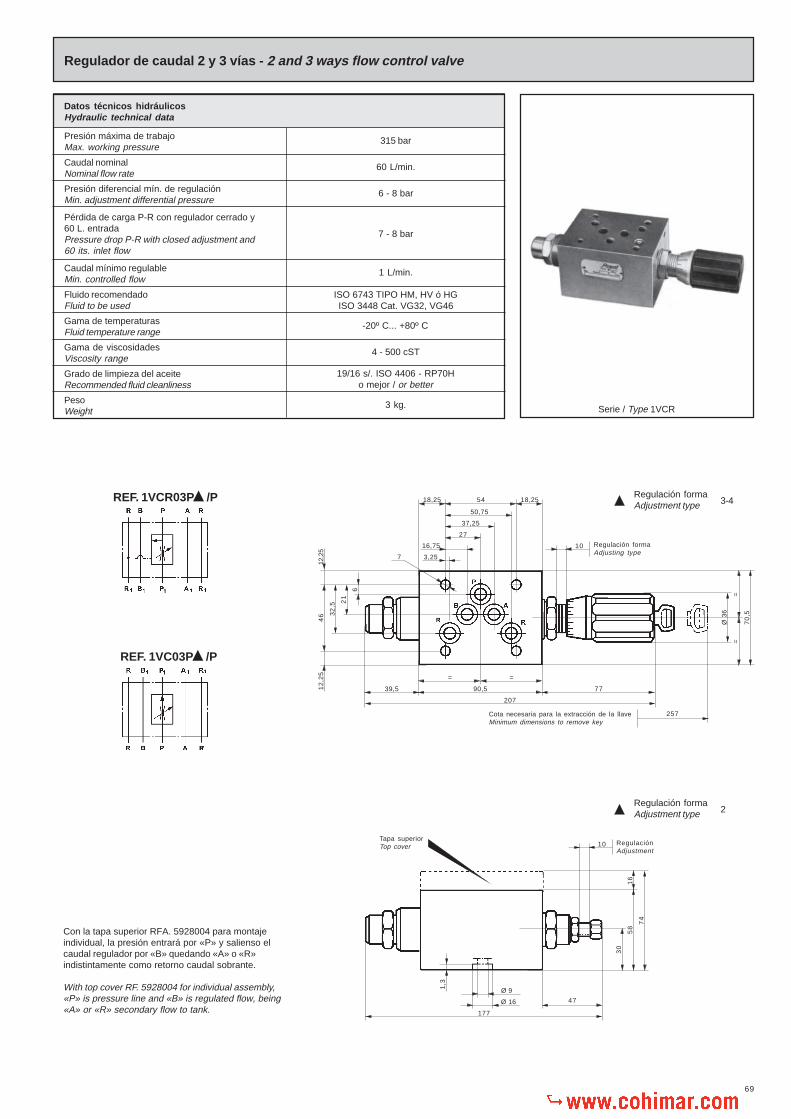
69
==
= =
90,5 77
207
18,2518,25
27
37,25
50,75
3,25
16,75
54
Regulador de caudal 2 y 3 vías - 2 and 3 ways flow control valve
REF. 1VCR03P /P
Con la tapa superior RFA. 5928004 para montajeindividual, la presión entrará por «P» y salienso elcaudal regulador por «B» quedando «A» o «R»indistintamente como retorno caudal sobrante.
With top cover RF. 5928004 for individual assembly,«P» is pressure line and «B» is regulated flow, being«A» or «R» secondary flow to tank.
39,5
70
,5
Ø 3
6257Cota necesaria para la extracción de la llave
Minimum dimensions to remove key
Tapa superiorTop cover
7
16
74
58
30
10 Regulación formaAdjusting type
10 RegulaciónAdjustment
Ø 9
Ø 16
177
47
Serie / Type 1VCR
Datos técnicos hidráulicosHydraulic technical data
Presión máxima de trabajoMax. working pressure
Caudal nominalNominal flow rate
Fluido recomendadoFluid to be used
Gama de temperaturasFluid temperature range
Gama de viscosidadesViscosity range
Grado de limpieza del aceiteRecommended fluid cleanliness
PesoWeight
315 bar
60 L/min.
ISO 6743 TIPO HM, HV ó HGISO 3448 Cat. VG32, VG46
-20º C... +80º C
4 - 500 cST
19/16 s/. ISO 4406 - RP70Ho mejor / or better
3 kg.
Caudal mínimo regulableMin. controlled flow
1 L/min.
Presión diferencial mín. de regulaciónMin. adjustment differential pressure
6 - 8 bar
Pérdida de carga P-R con regulador cerrado y60 L. entradaPressure drop P-R with closed adjustment and60 its. inlet flow
7 - 8 bar
46 3
2,5
21
6
12,2
51
2,2
5
1,3
Regulación formaAdjustment type 2
Regulación formaAdjustment type 3-4
REF. 1VC03P /P

70
Tornillo regulación
Junta tórica
Estrangulador
Corredera
Tornillo con taladro calibrado
Muelle
Tapón
Cuerpo regulador
Juntas tóricas
Adaptador
Pasador elástico
Tuerca regulación
Tuerca
Ø 8,9x1,9
Ø 12,4x1,78
Ø 3x12
Adjusting screw
O’ring
Restrictor
Spool
Orifice screw
Spring
Plug
Valve housing
O’rings
Adaptor
Elastic pin
Adjusting nut
Nut
Placa base individual
Tapa superior
Juntas tóricas para montaje individual
Juntas tóricas para montaje individual
Tornillos para fijación
Ejemplo para pedido de recambiosExample to order spare parts
CantidadQuantity
DenominaciónDescription
N.º de la piezaPart number
Referencia según la placaReference according serial number plate
1MuelleSpring 6
Para válvulaFor valve 1VCR03P3/P
RFE. 140001 - 140002 - 332003 - 332004
RFE. 5928004
2 Ø 24x2
1 Ø 12,4x1,78
4 M6x75 DIN-912 14 - 16 Nm.
Juntas tóricas
Junta tórica
Tornillos
O’rings
O’ring
Screws
Accesorios Requieren pedido por separadoAccessories That need separate orders
Sub-plate
Top cover
O’ring for individual mounting
O’ring for individual mounting
Screws for fixingPar de aprieteFit torque
Guía volante
Cerradura
Guía volante
Bolas
Pasador elástico
Muelle
Tapón tope bolas
Junta tórica
Adaptador volante
Junta metal-buna
Volante
Suplemento volante
Pasador elástico
1
1
1
30
2
2
1
1
1
1
1
1
1
Knob guide
Locking system
Knob guide
Balls
Elastic pin
Spring
Plug
O’ring
Knob adaptor
Metal bonded gasket
Knob
Knob cover
Elastic pin
Núm.No.
1
2
3
4
5
6
7
8
9
10
11
12
13
DenominaciónDescription
Cant.Qty.
Ø 2x20
Ø 16,9x2,7
Ø 3x18
1
1
1
1
1
1
1
1
5
1
1
1
1
Núm.No.
14
15
16
17
18
19
20
21
22
23
24
25
26
DenominaciónDescription
Cant.Qty.

71
Regulador de caudal 2 vías - 2 ways flow control valve
Serie / Type 1VCR
Datos técnicos hidráulicosHydraulic technical data
Presión máxima de trabajoMax. working pressure
Caudal nominalNominal flow rate
Fluido recomendadoFluid to be used
Gama de temperaturasFluid temperature range
Gama de viscosidadesViscosity range
Grado de limpieza del aceiteRecommended fluid cleanliness
PesoWeight
315 bar
60 L/min.
ISO 6743 TIPO HM, HV ó HGISO 3448 Cat. VG32, VG46
-20º C... +80º C
4 - 500 cST
19/16 s/. ISO 4406 - RP70Ho mejor / or better
3 kg.
Caudal mínimo regulableMin. controlled flow
1 L/min.
Presión diferencial mín. de regulaciónMin. adjustment differential pressure
6 - 8 bar
REF. 1VCR03P /A
REF. 1VCR03P /B
10 Ø 9
21
32
,5
46
12,2
51
2,2
5
18,2520,75
27
37,25
50,75
3,25
16,75
54
6
710
==
70
,5
Ø 3
6
93 24
194
77
245 Cota necesaria para la extracción de la llaveMinimum dimensions to remove key
Tapa superiorTop cover
16
74
58
30
Ø 16
164
47
1,3
RegulaciónAdjustment
18,25 20,7554
Regulación formaAdjustment type 2
Regulación formaAdjustment type 3-4
Regulación TomaOutlet adjustment B
Regulación TomaOutlet adjustment A

72
Placa base individual
Tapa superior
Juntas tóricas para montaje individual
Juntas tóricas para montaje individual
Tornillos para fijación
Pasador elástico
Tornillo regulación
Junta tórica
Estrangulador
Corredera
Guía muelle
Tapón
Tuerca
Muelle
Tornillo con taladro calibrado
Juntas tóricas
Válvula retención
Juntas tóricas
Tapón válvula
Muelle
Elastic pin
Adjusting screw
O’ring
Restrictor
Spool
Spring guide
Plug
Nut
Spring
Orifice screw
O’rings
Check valve
O’rings
Plug
Spring
Ejemplo para pedido de recambiosExample to order spare parts
CantidadQuantity
DenominaciónDescription
N.º de la piezaPart number
Referencia según la placaReference according serial number plate
1Válvula retención
Check valve 12Para válvulaFor valve 1VCR03P2/B
Cerradura
Guía volante
Guía volante
Bolas
Adaptador volante
Junta metal-buna
Pasador elástico
Muelle
Tapón tope bola
Junta tórica
Adaptador
Pasador elástico
Tornillo regulación
Tuerca
Volante
Locking system
Knob guide
Knob guide
Balls
Knob adaptor
Metal bonded gasket
Elastic pin
Spring
Plug
O’ring
Adaptor
Elastic pin
Adjusting screw
Nut
Knob
1
1
1
30
1
1
2
1
1
1
1
1
1
1
1
Núm.No.
16
17
18
19
20
21
22
23
24
25
26
27
28
29
30
DenominaciónDescription
Cant.Qty.
Ø 2x20
Ø 16,9x2,7
Ø 3x12
1
1
1
1
1
2
1
1
1
1
5
1
1
1
1
Núm.No.
1
2
3
4
5
6
7
8
9
10
11
12
13
14
15
DenominaciónDescription
Cant.Qty.
Ø 3x18
Ø 8,9x1,9
Ø 12,4x1,78
Ø 12,4x1,8
RFE. 140001 - 140002 - 332003 - 332004
RFE. 5928004
2 Ø 24x2
1 Ø 12,4x1,78
4 M6x75 DIN-912 14 - 16 Nm.
Juntas tóricas
Junta tórica
Tornillos
O’rings
O’ring
Screws
Accesorios Requieren pedido por separadoAccessories That need separate orders
Sub-plate
Top cover
O’rings for individual mounting
O’rings for individual mounting
Screws for fixingPar de aprieteFit torque

73
Regulador de caudal 3 vías - 3 ways flow control valve
Regulador de caudal 2 vías - Flow control valve 2 ways
Diagrama: Presión caudalDiagram: Pressure - Flow rate
210
15
20253035
10 13030 9050 11070
4045
505560
65
150 170 230190 210
Cau
dal s
alid
a re
gula
dor
en l/
min
.O
utpu
t con
trol
led
flow
rat
e l/m
in.
Presión entradaInlet pressure
bar
Diagrama: Presión caudalDiagram: Pressure - Flow rate
Curva sensibilidadMetering curve
10 13030 9050 11070 150 170 230190 250210
Presión entradaInlet pressure
bar
2
10
15
20
25
30
35
40
45
50
55
60
65
Cau
dal s
alid
a re
gula
dor
en l/
min
.O
utpu
t con
trol
led
flow
rat
e l/m
in.
Q =
L/m
in.
1 2 3 4 5 6 7
2
10
15
20
25
30
35
40
45
50
55
60
8 9
Nº de vueltasTurns
65
Q = L/min.
10 20 30 40 50 60 70
2
4
6
8
10
12
14
16
80
Regulador abierto almáximoFlow Control valvefully open
Regulador cerradoClosed flow control valve
p =
bar
250
Curva sensibilidadMetering curve
Q =
L/m
in.
1 2 3 4 5 6 7
2
10
15
20
25
30
35
40
45
50
55
60
8 9
Nº de vueltasTurns
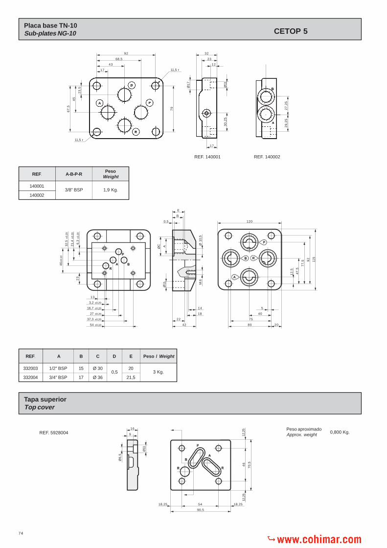
74
Ø 1
0,5
Ø11
Placa base TN-10Sub-plates NG-10
Tapa superiorTop cover
REF. A-B-P-RPeso
Weight
140001
1400023/8” BSP 1,9 Kg.
92
68,5
43
176
7,5
45
23
,5
79
11,5 r
11,5 r
32
23
12
Ø11
Ø1
7
30
,25
17
REF. 140001 REF. 140002
29
,25
27
,25
REF. A Peso / Weight
332003
3320040,5
B C D E
1/2” BSP
3/4” BSP
15
17
Ø 30
Ø 36
20
21,5
REF. 5928004Peso aproximadoApprox. weight 0,800 Kg.
20
21,4
±0,2
0
6,3
±0,2
02
3
46±
0,10
32,5
±0,2
0
3,2 ±0,20
16,7 ±0,20
27 ±0,20
37,3 ±0,20
54 ±0,10
13
42
22
14
18
ØC A
E
B
0,5
80
75
40
5
120
115
12
,5
47
,5
77
,5 92
16
9
Ø6
,5
Ø11
46
12,2
512
,25
70
,5
18,25 54 18,25
90,5
M.6
3 Kg.
CETOP 5
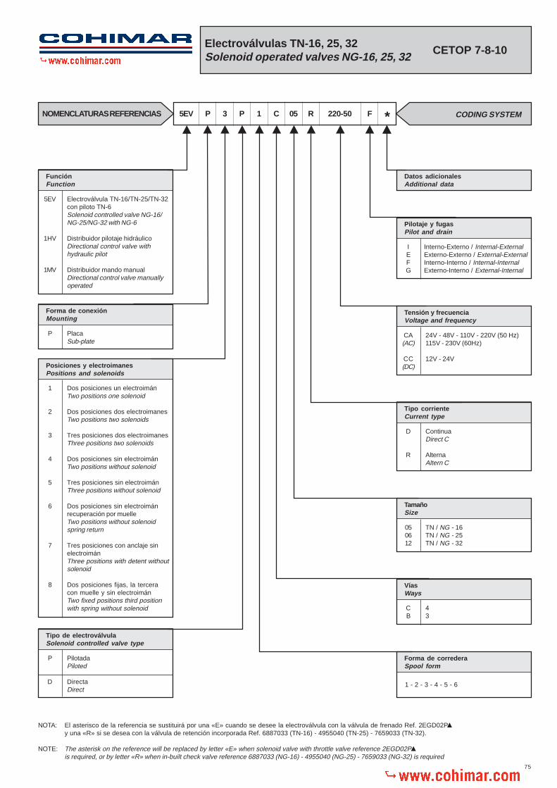
75
Electroválvulas TN-16, 25, 32Solenoid operated valves NG-16, 25, 32 CETOP 7-8-10
F *NOMENCLATURAS REFERENCIAS CODING SYSTEM5EV P 3 220-50R05C1P
FunciónFunction
Electroválvula TN-16/TN-25/TN-32con piloto TN-6Solenoid controlled valve NG-16/NG-25/NG-32 with NG-6
Distribuidor pilotaje hidráulicoDirectional control valve withhydraulic pilot
Distribuidor mando manualDirectional control valve manuallyoperated
5EV
1HV
1MV
Forma de conexiónMounting
PlacaSub-plate
P
Posiciones y electroimanesPositions and solenoids
Dos posiciones un electroimánTwo positions one solenoid
Dos posiciones dos electroimanesTwo positions two solenoids
Tres posiciones dos electroimanesThree positions two solenoids
Dos posiciones sin electroimánTwo positions without solenoid
Tres posiciones sin electroimánThree positions without solenoid
Dos posiciones sin electroimánrecuperación por muelleTwo positions without solenoidspring return
Tres posiciones con anclaje sinelectroimánThree positions with detent withoutsolenoid
Dos posiciones fijas, la terceracon muelle y sin electroimánTwo fixed positions third positionwith spring without solenoid
1
2
3
4
5
6
7
8
Tipo de electroválvulaSolenoid controlled valve type
PilotadaPiloted
DirectaDirect
P
D
Datos adicionalesAdditional data
Pilotaje y fugasPilot and drain
Interno-Externo / Internal-ExternalExterno-Externo / External-ExternalInterno-Interno / Internal-InternalExterno-Interno / External-Internal
IEFG
Tensión y frecuenciaVoltage and frequency
24V - 48V - 110V - 220V (50 Hz)115V - 230V (60Hz)
12V - 24V
CA(AC)
CC(DC)
Tipo corrienteCurrent type
ContinuaDirect C
AlternaAltern C
D
R
TamañoSize
TN / NG - 16TN / NG - 25TN / NG - 32
050612
VíasWays
43
CB
Forma de correderaSpool form
1 - 2 - 3 - 4 - 5 - 6
NOTA: El asterisco de la referencia se sustituirá por una «E» cuando se desee la electroválvula con la válvula de frenado Ref. 2EGD02Py una «R» si se desea con la válvula de retención incorporada Ref. 6887033 (TN-16) - 4955040 (TN-25) - 7659033 (TN-32).
NOTE: The asterisk on the reference will be replaced by letter «E» when solenoid valve with throttle valve reference 2EGD02Pis required, or by letter «R» when in-built check valve reference 6887033 (NG-16) - 4955040 (NG-25) - 7659033 (NG-32) is required

76
38 W
180 VA
65 VA
12V - 24V
ED 100%
IP - 65
Unom ± 10%
Eléctricos
Consumo por electroimán
Corriente continua
Gama de tensiones para C.C.
Gama de tensiones para C.A.
Factor de marcha
Protección según DIN-40050
Tolerancia de la tensión
Frecuencia de conexión
Tiempos de respuesta
Conectado / Switch-on
24V - 48V - 110V - 220V (50 Hz)115V - 230V (60 Hz)
Electrical
Consumption per solenoid
D.C.
D.C. voltage range
A.C. voltage range
Operating factor
Protection to DIN-40050
Voltage tolerance
Switching frequency
Response time
Desconectado / Switch-off
Continua / D.C. = Max. 15000/h.Alterna / A.C. = Max. 7200/h.
ContinuaD.C
AlternaA.C.
20 - 60 ms.50 - 70 ms.
10 - 25 ms.25 - 50 ms.
Corriente alternaA.C.
Circuito abiero
Circuito cerrado
Open circuit
Closed circuit
Sistemas de distribución estandardStandard distribution systems
5EVP3P1C...
5EVP2P2C...
5EVP3P2C...
5EVP3P3C...
5EVP3P4C...
5EVP3P5C...
5EVP3P6C...
1
2
2
3
4
5
6
P (1) R A y B (2)
A, B, P y R (2)
P (2) A y B (1) R
A, B y P (1) R
A (1) R B y P (2)
A (2) B y P (1) R
P (1) A B (2) R
P (1) B A (2) R
P (1) B A (2) R
P (1) A B (1) R
P (1) B A (1) R P (1) A B (1) R
Solenoide conectadoSolenoid switch-on
Solenoide desconectadoSolenoid switch-off
5EVP1P2C... 2
ReferenciaReference
Forma de lacorredera
Spool form
SímboloSymbol
Circulación del aceiteConnections
Solenoide A conectadoSolenoid A switched on
Posición centralCentral position
Solenoide B conectadoSolenoid B switched on
(1) Comunica / Connected (2) Cerrado / Closed
NOTA: Para completar la referencia ver nomenclatura general pág. 75 / NOTE: To complete the reference see general coding system page 75.
Tamaño
Hidráulicos
Presión máxima de trabajo
Caudal nominal (véase diagramas pág. 84)
Presión nominal en retorno
Fluido recomendado
Gama de temperaturas del fluido
Gama de viscosidades
Grado de limpieza del aceite
ISO 6743 TIPO HM, HV ó HGISO 3448 Cat. VG32, VG46
-20º C... +80º C
4 - 500 cST
19/16 s/. ISO 4406 - RP70Ho mejor / or better
Size
Hydraulic
Max. working pressure
Nominal flow rate (see diagrams pag. 84)
Nominal pressure in return
Fluid to be used
Fluid temperature range
Viscosity range
Recommended fluid cleanliness
TN / NG - 16 TN / NG - 25 TN / NG - 32
350 bar
200 L/min. 350 L/min. 700 L/min.
350 bar
Datos técnicosTechnical data
A B

77
Electroválvula TN-16Solenoid operated valve NG-16
52,7 88,1
21,7 66
50
34,15
18,3
55
,669
,85
1,6
71
,45
14
,3
52,7
1,576,6
101,6
50
34,15
18,3
15
,9
57
,2
10
11
5
14
7
20
26,5
212 C.A / A.C.242 C.C. / D.C.
207
2
1,5
44
1
28
Ø3
90
18
1
4
17
1
209
Con
vál
vula
de
fren
ado
/ W
ith b
rake
val
ve
P Entrada de presiónPressure inlet port
A y B Tomas a cilindros o motoresOutlet ports to cylinders or motors
R Retorno a depósitoReturn to tank
X Entrada presión pilotaje externoExternal pilot oil inlet
Y Retorno externo de pilotajePilot external return
PesoWeight
8 Kg
NOTA: La presión de pilotaje deberá ser de 4 bar mínimaNOTE: Pilot pressure must be 4 bar minimum

78
V
Electroválvula TN-25, 32Solenoid operated valve NG-25, 32
REF. C D E F G H I J K L M N O S WVUT Z
TN-25
TN-32
55
75
11
20
12,5
21
130
190,5
92
158,7
74,5
123,8
19
44,5
15
39
5
-
73
130,2
17,5
34,9
113
168,3
94,5
147,6
29,5
41,3
100,5
147,6
77
114,3
53
82,5
29,5
41,3
17
41,3
TN-25
TN-32
REF. a b c d e f g h i j k l m n r
-
76,2
239
289
211
261
200
250
5
5
6
6
1,5
1
43,5
49
25
25
6
7
2,3
2,3
33
48
24
38
264
360,5
79
95
Peso / Weight Kg.
13
34
C
P Entrada de presiónPressure inlet port
A y B Tomas a cilindros o motoresOutlet ports to cylinders or motors
R Retorno a depósitoReturn to tank
X Entrada presión pilotaje externoExternal pilot oil inlet
Y Retorno externo de pilotajePilot external return
NOTA: La presión de pilotaje deberá ser de 4 bar mínimaNOTE: Pilot pressure must be 4 bar minimum
b
D
E
F
G
U aZ
T
L
K
M
N O
S
212 C.A. / A.C.242 C.C. / D.C.
hi
ee
Ø c
Ø d
Ø f
Ø g
n C
on v
álvu
la d
e fr
enad
o /
With
bra
ke v
alve
Ø j
kl
m
W
H
r
I
J

79
Conjunto electroválvula
Tornillos
Tor. Montaje estrangulador
Arandelas
Juntas tóricas
Muelle
Juntas tóricas
Tapas laterales
Arandela tope muelle
Juntas tóricas
DIN-912
DIN-7980 Ø5
Pasador elástico
Juntas tóricas
Corredera
Tornillos
Arandelas
Tapones
Junta metal-buna
Tapones
Vál. Frenado para electroválvula
Cuerpo electroválvula
DIN-912
DIN-7980
DIN-912 1/8”
1/8”
1/16”
Ejemplo para pedido de recambiosExample to order spare parts
CantidadQuantity
DenominaciónDescription
N.º de la piezaPart number
Referencia según la placaReference according serial number plate
2Tapas laterales
Side covers 8Para válvulaFor valve 5EVP3P1C05R
Solenoid valve
Screws
Screws
Washers
O’rings
Spring
O’rings
Side covers
Spring stop washer
O’rings
Núm.No.
1
2
3
4
5
6
7
8
9
10
DenominaciónDescription
Cant.Qty.
1
4
4
4
2
2
2
2
2
2
Spring
Screws
Washers
O’rings
Sub-plate
Plug
Plug
Metal bonded gasket
Muelle para dos posiciones
Tornillos
Arandelas
Juntas tóricas
Placa base para electroválvula
Tapones
Tapones
Junta metal-buna
DenominaciónDescription
Cant.Qty.
1
4
4
5
1
-
2
2
DIN-912 M6X30
DIN-7980 Ø6
1/8”
DIN-908 1/4”
Núm.No.
21
22
23
24
25
26
27
28
Elastic pin
O’rings
Spool
Screws
Washers
Plug
Metal bonded gasket
Plug
Brake val. for solenoid valve
Valve housing
Núm.No.
11
12
13
14
15
16
17
18
19
20
DenominaciónDescription
Cant.Qty.
1
4
1
8
8
2
2
-
1
1
4 DIN-912 M10 x 60 42-47 Nm.
2 DIN-912 M6 x 60 14-16 Nm.
6 DIN-912 M12 x 65 110-120 Nm.
6 DIN-912 M20 x 75 550-600 Nm.
TN
25
32
Placa base individualSub-plate
Accesorios Requieren pedido por separadoAccessories That need separate orders
Screws
Screws
Screws
Screws
Tornillos
Tornillos
Tornillos
Tornillos
16 316001 - 316002
141001 - 141002 - 141003
142001 - 142002 - 142003
Fit torque
Fit torque
Fit torque
Fit torque
Par de apriete
Par de apriete
Par de apriete
Par de apriete
Tornillos sujeción a la placa baseScrews for fixing valve to sub-plate
Con tapón, retorno externoWith plug, ext. return
Sin tapón, retorno internoWithout plug, int. return
TN / NG - 16
TN / NG - 25 TN / NG - 32
Tres posiciones con muelleThree positions with spring
Dos posiciones sin muelleTwo positions without spring
Con tapón, pilotaje externoWith plug, ext. pilot
Sin tapón, pilotaje internoWithout plug, int. pilot
Con tapón, pilotaje externoWith plug, ext. pilot
Sin tapón, pilotaje internoWithout plug, int. pilot
Con tapón, retorno externoWith plug, ext. return
Sin tapón, retorno internoWithout plug, int. return
Con tapón, retorno externoWith plug, ext. return
Sin tapón, retorno internoWithout plug, int. return
Con tapón, pilotaje externoWith plug, ext. pilot
Sin tapón, pilotaje internoWithout plug, int. pilot

80
TN / NG - 16
Válvula para pilotaje interno en sistemas de distribución de centro abiertoValve for internal pilot in open centre directional control systems
Ref. 6887033 (TN / NG - 16)Ref. 4955040 (TN / NG - 25)Ref. 7951033 (TN / NG - 32)
25 50 75 100 125 150 175
1
2
3
4
5
6
7
8
9
10
11
200
Q = L/min.
p =
bar
TN / NG - 32
100 200 300 400 500 600 700
1
2
3
4
5
6
7
8
9
10
11
Q = L/min.
p =
bar
TN / NG - 25
50 100 150 200 250 300 350
1
23
45
6
789
10
11
Q = L/min.
p =
bar
400
(1) Comunica / Connected (2) Cerrado / Closed
NOTA: Para completar la referencia ver nomenclatura general pág. 75NOTE: To complete the reference see general coding system page 75.
P (1) R A y B (2)
A, B, P y R (2)
P (2) A y B (1) R
A, B, P (1) R
A (1) R B y P (2)
A (2) B y P (1) R
Forma de lacorredera
Spool form
SímboloSymbolReferencia
Reference
Circulación del aceite / Connections
1HV 1MV
1HV
1MV
PilotajePilot X
PilotajePilot Y
Posición centralCentral positionPos. inferior
Bot. position
P (1) A B (1) R
P (1) B A (1) R
P (1) B A (1) R
P (1) A B (1) R
Pos. superiorTop position
1
2
2
3
4
5
6
2
1• VP5 1C
1• VP5 2C
1• VP4 2C
1• VP5 3C
1• VP5 4C
1• VP5 5C
1• VP5 6C
1• VP6 2C
Sistema de distribución estandardStandard distribution system
12
YX

81
Hidroválvula TN-16D. control valve hydr. pilot NG-16
P Entrada de presiónPressure inlet port
A y B Tomas a cilindros o motoresOutlet ports to cylinders or motors
R Retorno a depósitoReturn to tank
X - Y Entrada de pilotajePilot inlet
PesoWeight 6,5 Kg
NOTA: La presión de pilotaje deberá ser de 4 bar mínimaNOTE: Pilot pressure must be 4 bar minimum
136
Con
vál
vula
de
fren
ado
/ W
ith b
rake
val
ve
71
,45
52,7 88,1
21,7 66
50
34,15
18,3
55
,669
,55
1,6
14
,3
52,7
1,576,6
101,6
50
34,15
18,3
15
,9
57
,2
10
11
5
14
7
20
26,5
207
2
1,5
44
1
46
Ø3
90
4
10
8
65
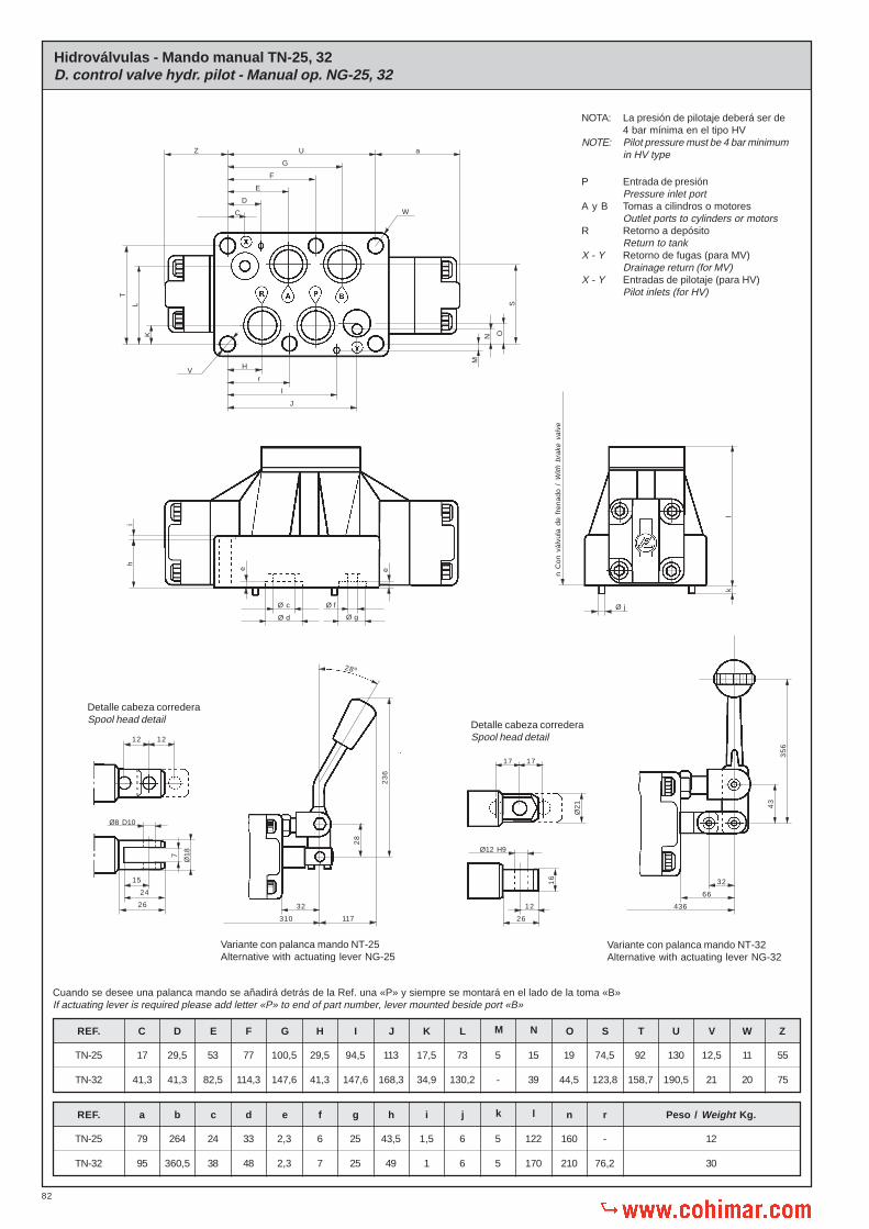
82
J
I
r
H
E
F
G
U
S
Hidroválvulas - Mando manual TN-25, 32D. control valve hydr. pilot - Manual op. NG-25, 32
REF. C D E F G H I J K L M N O S WVUT Z
TN-25
TN-32
55
75
11
20
12,5
21
130
190,5
92
158,7
74,5
123,8
19
44,5
15
39
5
-
73
130,2
17,5
34,9
113
168,3
94,5
147,6
29,5
41,3
100,5
147,6
77
114,3
53
82,5
29,5
41,3
17
41,3
TN-25
TN-32
REF. a b c d e f g h i j k l n r
-
76,2
160
210
122
170
5
5
6
6
1,5
1
43,5
49
25
25
6
7
2,3
2,3
33
48
24
38
264
360,5
79
95
Peso / Weight Kg.
12
30
C
P Entrada de presiónPressure inlet port
A y B Tomas a cilindros o motoresOutlet ports to cylinders or motors
R Retorno a depósitoReturn to tank
X - Y Retorno de fugas (para MV)Drainage return (for MV)
X - Y Entradas de pilotaje (para HV)Pilot inlets (for HV)
NOTA: La presión de pilotaje deberá ser de4 bar mínima en el tipo HV
NOTE: Pilot pressure must be 4 bar minimumin HV type
D
aZ
T
L
K
M
N O
hi
ee
Ø c
Ø d
Ø f
Ø g
W
V
n C
on v
álvu
la d
e fr
enad
o /
With
bra
ke v
alve
Ø j
kl
Detalle cabeza correderaSpool head detail
12 12
Ø1
8
7
Ø8 D10
15
24
26
310
32
117
28
23
6
28º
Variante con palanca mando NT-25Alternative with actuating lever NG-25
Detalle cabeza correderaSpool head detail
17 17
Ø2
1
Ø12 H9
12
26
16
Variante con palanca mando NT-32Alternative with actuating lever NG-32
32
66
436
43
35
6
Cuando se desee una palanca mando se añadirá detrás de la Ref. una «P» y siempre se montará en el lado de la toma «B»If actuating lever is required please add letter «P» to end of part number, lever mounted beside port «B»

83
Puño palanca mando
Palanca mando
Anillo elástico
Pasador
Pieza unión palanca mando
Pieza fij. 2 pos. (inter-extrema)
Pieza fijación 2 pos. (extremas)
Pieza fijación 3 posiciones
Bola fijación posiciones
Junta cobre
Tornillo fijación anclaje
Cabeza corredera
Muelle fijación anclaje
Tornillos
Tornillos
Arandelas
Anillo tope cabeza corredera
Anillo tope muelle
Tuerca
Palanca mando
Puño palanca mando
Pieza sujeción palanca mando
Tuerca
Tornillo fijación palanca
Pasador
Anillo rascador polvo
Junta tórica
Cabeza corredera
Tapa soporte palanca mando
Núm.No.
16
17
18
19
20
21
22
23
24
25
26
27
28
29
30
DenominaciónDescription
Cant.Qty.
4
4
1
1
1
1
1
1
1
1
1
1
1
1
1
DIN-912
DIN-7980
DIN-936
DIN-1481
4 DIN-912 M10 x 60 42-47 Nm.
2 DIN-912 M6 x 60 14-16 Nm.
6 DIN-912 M12 x 65 110-120 Nm.
6 DIN-912 M20 x 75 550-600 Nm.
TN
25
32
Referencia placa base individualReference sub-plate
Accesorios Requieren pedido por separadoAccessories That need separate orders
Screws
Screws
Screws
Screws
Tornillos
Tornillos
Tornillos
Tornillos
16 316001 - 316002
141001 - 141002 - 141003
142001 - 142002 - 142003
Fit torque
Fit torque
Fit torque
Fit torque
Par de apriete
Par de apriete
Par de apriete
Par de apriete
Tornillos sujeción a la placa baseScrews for fixing valve to sub-plate
Ejemplo para pedido de recambiosExample to order spare parts
CantidadQuantity
DenominaciónDescription
N.º de la piezaPart number
Referencia según la placaReference according serial number plate
1Anillo tope muelleSpring stop bush 19
Para distribuidorFor valve
1MVP5D1C06 P
Side covers
O’rings
Screws
Washers
O’rings
Top cover
Connection plate
Spring stop ring
Spool return spring
O’rings
O’rings
Valve housing
Elastic pin
O’rings
Spool
Tapas laterales
Juntas tóricas
Tornillos
Arandelas
Juntas tóricas
Tapa superior
Placa comunicación
Anillo tope muelle
Muelle recuperación corredora
Juntas tóricas
Juntas tóricas
Cuerpo electroválvula
Pasador elástico
Juntas tóricas
Corredera
Núm.No.
1
2
3
4
5
6
7
8
9
10
11
12
13
14
15
DenominaciónDescription
Cant.Qty.
2
2
4
4
2
1
1
2
2
2
4
1
1
2
1
DIN-912
DIN-7980
Ø 20,63x2,62
Núm.No.
31
32
33
34
35
36
37
38
39
40
41
42
43
44
DenominaciónDescription
Cant.Qty.
1
1
6
3
2
1
1
1
2
2
2
1
2
4DIN-912
Palanca mando TN-32Actuating lever NG-32
Palanca mando TN-25Actuating lever NG-25
Variante con anclajeAlternative with detent
Screws
Washers
Spool head stop bush
Spring stop ring
Nut
Lever
Lever knob
Lever fixing part
Nut
Lever fixing screw
Pin
Dust scraper
O’ring
Spool head
Lever support cover
Lever knob
Lever
Circlip
Pin
Lever connecting part
2 posit. spring part (int. end)
2 posit. spring part (both ends)
3 positions spring part
Detent ball
Cooper gasket
Detent fixing screw
Spool head
Spring
Screws

84
Corredera formaSpool Form
Corredera formaSpool Form
Corredera formaSpool Form
Correderas formasSpool Forms
Correderas formasSpool Forms
Correderas formasSpool Forms
TN / NG - 16
DiagramasDiagrams p-Q a 27 cSt.
1 - 4
6
6
1 - 4
6
1 - 4 - 6
TN / NG - 25 TN / NG - 32
25050 300100 150
2
4
6
8
10
12
14
16
18
20
22
200
Q = L/min.
p =
bar
25050 300100 150
2
4
6
8
10
12
14
16
18
20
22
200
Q = L/min.
p =
bar
B - R
A - R
P - B
P - A
P R
Corredera formaSpool Form 6
Corredera formaSpool Form 1
Corredera formaSpool Form 4
Correderas formasSpool FormsCorredera formaSpool Form
Corredera formaSpool Form
Correderas formasSpool Forms
Correderas formasSpool Forms
Correderas formasSpool Forms
3
456
2
500100 600200 300
2
4
6
8
10
12
14
400
Q = L/min.
700 800
1
16
18
20
900 1000
345
6
2
p =
bar
25050 300100 150
2
4
6
8
10
12
14
200
Q = L/min.
p =
bar
350 400
1
1
6
4
1-2-3-4-5-6
1
2-3-4-5-6
25050 300100 150
2
4
6
8
10
12
14
16
18
20
22
200
Q = L/min.
p =
bar
5
432
1
Correderas formasSpool Forms 2 - 3 - 5
Corredera formaSpool Form
Corredera formaSpool Form
Corredera formaSpool Form
Corredera formaSpool Form
Correderas formasSpool Forms
Correderas formasSpool Forms
Corredera formaSpool Form
Corredera formaSpool Form
Correderas formasSpool Forms
1
1
4
1
2-3-4-6
2-3
5
5
4-6
1: P A ó B
P B
2: P A
3: A R
4: A R
5: B R
1: P R
2: P R
3: A R
4: A ó B R
5: P A ó B
6: P A ó B
1: P R
2: A ó B R
3: P R
4: P A ó B
A ó B R
P A ó B
5: P A ó B
A ó B R
6: P A ó B

85
Elastic pin
Adjusting knob
Plugs and screw guides
Balls
O’rings
Valve body
O’rings
Pasador elástico
Volante regulación
Tapón guía tornillo estrangulador
Bolas
Juntas tóricas
Cuerpo válvula
Juntas tóricas
Núm.No.
1
2
3
4
5
6
7
DenominaciónDescription
Cant.Qty.
2
2
2
2
2
1
4
DIN-1481 Ø 2X20
Ø 6,5
Ø 3,4X1,9
Ø 8X12
Ball stop elastic pin
Metal bonded gasket
Adjusting screw
Plugs and screw guides
Nut
Adjusting screw
Pasador elástico tope bola
Junta metal-buna
Tornillo estrangulador
Tapón guía tornillo estrangulador
Contratuerca
Tornillo estrangulador
Núm.No.
8
9
10
11
12
13
DenominaciónDescription
Cant.Qty.
2
2
2
2
2
2
Ejemplo para pedido de recambiosExample to order spare parts
CantidadQuantity
DenominaciónDescription
N.º de la piezaPart number
Referencia según la placaReference according serial number plate
2Volante regulación
Adjusting knob 2Para válvulaFor valve 2EGD02P2
Válvula de frenado para electroválvulasBrake valve for solenoid controlled valves
20,5
REF. 2EGD02P2
REF. 2EGD02P1
10,3
40,5
5,5
19
27,8
=
32
,5
=
26
,6
16
,3
6=
106
20,5 65
=
46
31
==
28
==
Ø2
2
4 RegulaciónAdjusting
Ø6,5
Ø12
27,5 27,565
120
1,6

86
Sub-plate
Top cover
O’rings for individual mounting
O’rings for individual mounting
Screws for fixing to sub-plate
Placa individual
Tapa superior
Juntas tóricas para montaje individual
Juntas tóricas para montaje individual
Tornillos para la sujeción de la placa base
REF. 140001 - 140002 ó 140003
REF. 5845016
2 Ø 14 x 3
2 Ø 67 x 3
4 M12 x 130 DIN-912 110 - 120 Nm.
Válvula retención pilotada TN-25Pilot check valve NG-25
Datos técnicos hidráulicosHydraulic technical data
Presión máxima de trabajoMax. working pressure
Caudal nominalNominal flow rate
Fluido recomendadoFluid to be used
Gama de temperaturasFluid temperature range
Gama de viscosidadesViscosity range
Grado de limpieza del aceiteRecommended fluid cleanliness
PesoWeight
350 bar
180 L/min.
ISO 6743 TIPO HM, HV ó HGISO 3448 Cat. VG32, VG46
-20º C... +80º C
4 - 500 cST
19/16 s/. ISO 4406 - RP70Ho mejor / or better
1,2 kg.
Relación descompresiónDecompression ratio 1 : 19
Relación aperturaOpening ratio 1 : 2,5
Según necesidadesAs per requirements
P Entrada de presiónPressure inlet port
A y B Tomas a cilindros o motoresOutlet ports to cylinders or motors
R Retorno a depósitoReturn to tank
X - Y Entradas de pilotajePilot inlets
REF. VRHD06P1
REF. VRHS06P1/A
35
114
80
Accesorios Requieren pedido por separadoAccessories That need separate orders
Par de aprieteFit torque
O’rings
O’rings
Screws
Juntas tóricas
Juntas tóricas
Tornillos
80
24
92
6 Taladros Ø12,5
6 Holes Ø 12,5
2,3
77
13 77
17
53
100,5
57
53 35
37
17
,5
29,5
53
113
222
17
56
1111
36
Ø25Ø 33
178
215
Tapa superior montaje indivudualIndividual assembly top cover
35,5
35
50 100 150 200 250
2
4
6
8
10
Q = L/min.
p =
bar
0
Diagrama:Diagram: p-Q a 23 cST.

87
Placa base para TN - 16Sub-plates NG - 16
Placa base para TN - 25Sub-plates for NG - 25
141001
141002
141003
D E
3/4” BSP
1” BSP
3/4” BSP
-
-
1/2” BSP
ReferenciaReference
-
-
17,5
-
2,5
-
4,7
G HPeso
Weight
18
1/4” BSP
Ø 22
54,5
E
92
73
74
,5
180
102
54,5
G
125
78
42 E
H
17
,5
138
102
H
19
Ø 1
1
Ø 2
2
23
21,5
152
Ø 22
D D
12
35
23
E
1/4” BSP
11r
316001
316002
ReferenciaReference
PesoWeight Kg.
31
33
1/2”
3/4”
16
18
29
32
43
44
69,2
77
83
89
100
112
113
124
3,150
3,300
C LKJHGFED(BSP)
G
JL
14,5
55,5
F
K
H
10r
1
17
Ø 1
4
Ø 9
C
14
E
D1
/4”
BS
P
70
SecciónSection Y - Y
SecciónSection X - X
X Y
X Y
14
0
SecciónSection Y - Y
X
Y
Y
X
SecciónSection X - X

88
Ø Q
Placa base para TN-32 - Sub-plates NG-32
206,55
185,5 192
152,5
120,75
79,55
158,75
123,85
114,25
34,95
28,55
79,55 72
267
28
45
17
29
30
230
38
9
1 1/4” BSP 1 1/2” BSP
22
15
3/8” BSP
20
15,5
141001ReferenciaReference 141002
C
D
E
F
G
H
I
J
K
L
M
N
O
P
Q
R
S
T
U
V
W
Z
a
b
c
PesoWeight
C
D
E
F
JI
H
K
N
G
L
M
G
S
R
Ø O
REF. 142003
28
3/8” BSP
Ø 38
29
54
267
114
108,5
215,5
200,5
158,5
65,5
15
8,7
5
52,5
39
,5
13
0
22
113
,5
28
30
Ø 1
7
Ø 2
2
230
15
2” BSP
Peso aproximadoApprox. weight
15,5 Kg.
Kg
20r
c
ZS
W
Ø U Ø V
T
p
b
a
SecciónSection X - X
SecciónSection Y - Y
SecciónSection Y - Y
X
Y
Y
Y
X X


![Superficie Limitadora de Obstaculos GRUPO 7[1]](https://img.pdfslide.us/doc/110x75/5515a6dc497959fd1d8b4f00/superficie-limitadora-de-obstaculos-grupo-71.jpg)
