Embed Size (px)
Citation preview
Indiana University – Purdue University Fort WayneOpus: Research & Creativity at IPFWManufacturing & Construction EngineeringTechnology and Interior Design Senior DesignProjects
School of Engineering, Technology and ComputerScience Design Projects
4-27-2015
Electrostatic PrecipitatorCasey SpurgeonIndiana University - Purdue University Fort Wayne
Dan CummingsIndiana University - Purdue University Fort Wayne
Chandler TraceyIndiana University - Purdue University Fort Wayne
Follow this and additional works at: http://opus.ipfw.edu/etcs_seniorproj_mcetid
Part of the Mechanical Engineering Commons
This Senior Design Project is brought to you for free and open access by the School of Engineering, Technology and Computer Science Design Projectsat Opus: Research & Creativity at IPFW. It has been accepted for inclusion in Manufacturing & Construction Engineering Technology and InteriorDesign Senior Design Projects by an authorized administrator of Opus: Research & Creativity at IPFW. For more information, please [email protected].
Opus CitationCasey Spurgeon, Dan Cummings, and Chandler Tracey (2015). Electrostatic Precipitator.http://opus.ipfw.edu/etcs_seniorproj_mcetid/281
Electrostatic Precipitator IPFW MET Senior Design Spring 2015
Sponsored by Graphite Customs LLC.
Members: Casey Spurgeon
Dan Cummings
Chandler Tracey
4/27/2015
Senior Design – Spring 2015 1
Table of Contents
Introduction…………………………………………………………………………………………………….2
Background & Problem Statement…………………………………………………………………..2
Solution ………………………………………………………………………………………………………….2
Design Parameters…………………………………………………………………………………………..3
Electrostatic Precipitator ………………………………………………………………………………..3
Components…………………………………………………………………………………………………….4
Science behind an Electrostatic Precipitator…………………………………………………….5
Proof of Concept……………………………………………………………………………………………..5
Design Calculations………………………………………………………………………………………….6
Initial design……………………………………………………………………………………….6
Revised design…………………………………………………………………………………….7
Fabrication Procedure……………………………………………………………………………………..8
Overall cost……………………………………………………………………………………………………..9
Test results and comparison to initial performance specs. ………………………………9
Conclusion……………………………………………………………………………………………………….11
Gantt Chart………………………………………………………………………………………………………11
Bibliography…………………………………………………………………………………………………….12
Senior Design – Spring 2015 2
Introduction
This paper will outline the design and process for building an electrostatic precipitator (ESP). This is
presented as an approach to containing graphite powder while machining. It will cover the purpose, the
design calculations, the fabrication, test results, overall cost, and the conclusions we discovered in the
process.
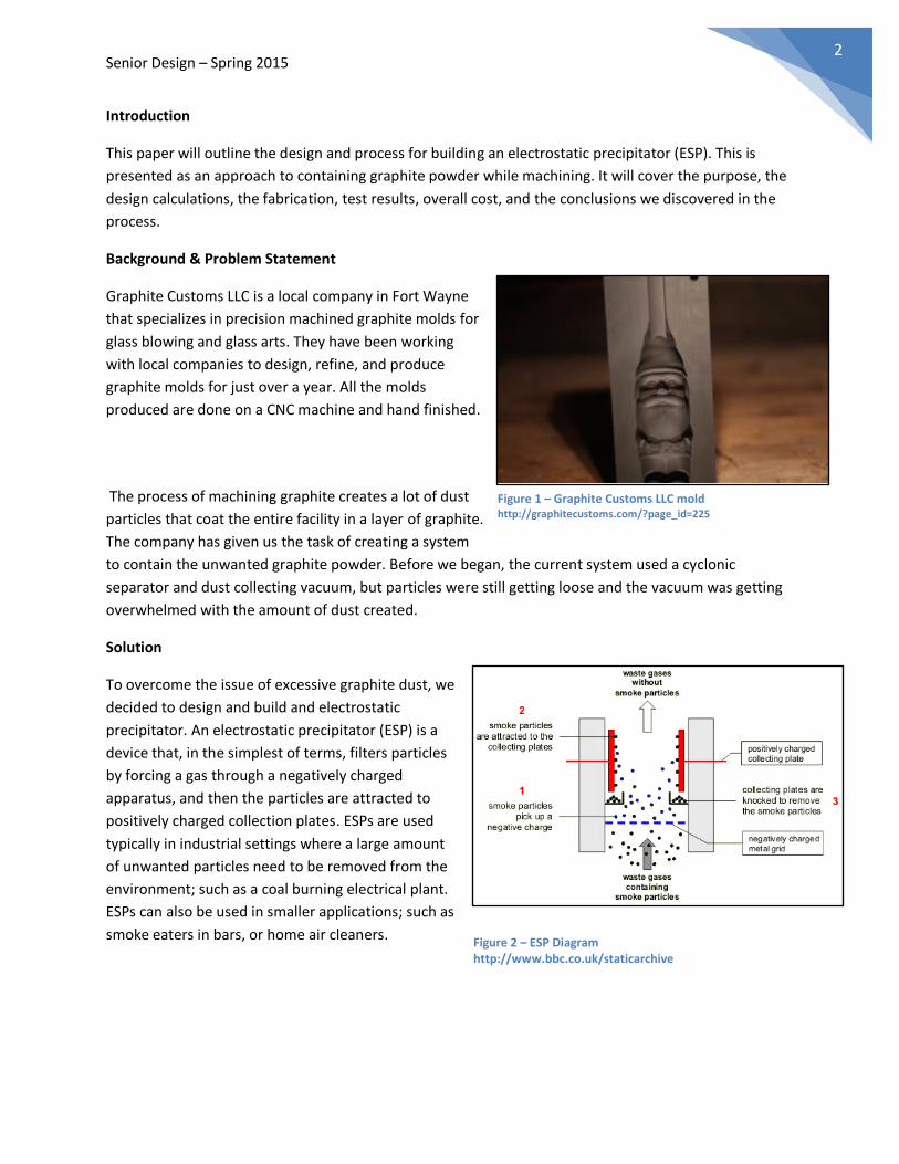
Background & Problem Statement
Graphite Customs LLC is a local company in Fort Wayne
that specializes in precision machined graphite molds for
glass blowing and glass arts. They have been working
with local companies to design, refine, and produce
graphite molds for just over a year. All the molds
produced are done on a CNC machine and hand finished.
The process of machining graphite creates a lot of dust
particles that coat the entire facility in a layer of graphite.
The company has given us the task of creating a system
to contain the unwanted graphite powder. Before we began, the current system used a cyclonic
separator and dust collecting vacuum, but particles were still getting loose and the vacuum was getting
overwhelmed with the amount of dust created.
Solution
To overcome the issue of excessive graphite dust, we
decided to design and build and electrostatic
precipitator. An electrostatic precipitator (ESP) is a
device that, in the simplest of terms, filters particles
by forcing a gas through a negatively charged
apparatus, and then the particles are attracted to
positively charged collection plates. ESPs are used
typically in industrial settings where a large amount
of unwanted particles need to be removed from the
environment; such as a coal burning electrical plant.
ESPs can also be used in smaller applications; such as
smoke eaters in bars, or home air cleaners.
Figure 1 – Graphite Customs LLC mold http://graphitecustoms.com/?page_id=225
Figure 2 – ESP Diagram http://www.bbc.co.uk/staticarchive
Senior Design – Spring 2015 3
Design Parameters
Greater than 95% containment of particles
Price of under $250
Conscientious of ESP size
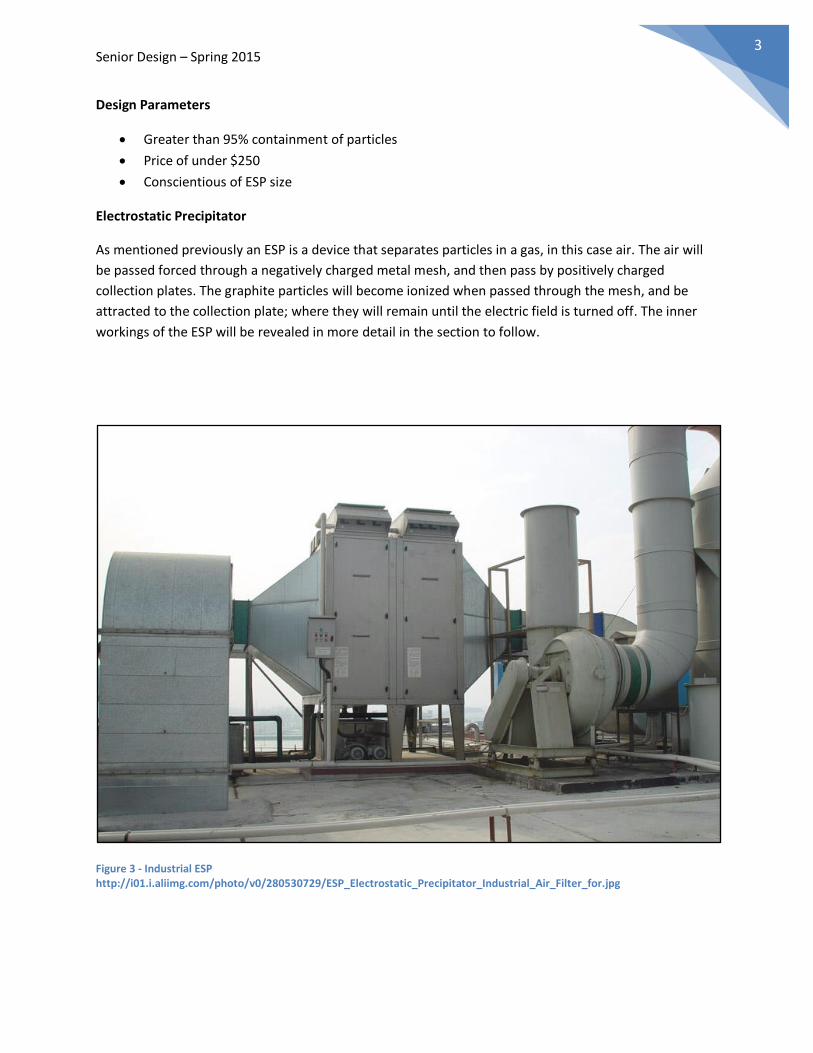
Electrostatic Precipitator
As mentioned previously an ESP is a device that separates particles in a gas, in this case air. The air will
be passed forced through a negatively charged metal mesh, and then pass by positively charged
collection plates. The graphite particles will become ionized when passed through the mesh, and be
attracted to the collection plate; where they will remain until the electric field is turned off. The inner
workings of the ESP will be revealed in more detail in the section to follow.
Figure 3 - Industrial ESP http://i01.i.aliimg.com/photo/v0/280530729/ESP_Electrostatic_Precipitator_Industrial_Air_Filter_for.jpg
Senior Design – Spring 2015 4
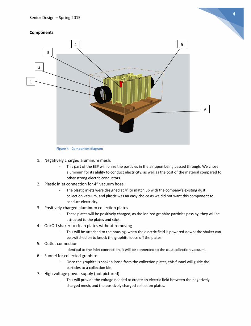
Components
1. Negatively charged aluminum mesh.
- This part of the ESP will ionize the particles in the air upon being passed through. We chose
aluminum for its ability to conduct electricity, as well as the cost of the material compared to
other strong electric conductors.
2. Plastic inlet connection for 4” vacuum hose.
- The plastic inlets were designed at 4” to match up with the company’s existing dust
collection vacuum, and plastic was an easy choice as we did not want this component to
conduct electricity.
3. Positively charged aluminum collection plates
- These plates will be positively charged, as the ionized graphite particles pass by, they will be
attracted to the plates and stick.
4. On/Off shaker to clean plates without removing
- This will be attached to the housing, when the electric field is powered down; the shaker can
be switched on to knock the graphite loose off the plates.
5. Outlet connection
- Identical to the inlet connection, it will be connected to the dust collection vacuum.
6. Funnel for collected graphite
- Once the graphite is shaken loose from the collection plates, this funnel will guide the
particles to a collection bin.
7. High voltage power supply (not pictured)
- This will provide the voltage needed to create an electric field between the negatively
charged mesh, and the positively charged collection plates.
1
2
3
4 5
6
Figure 4 - Component diagram
Senior Design – Spring 2015 5
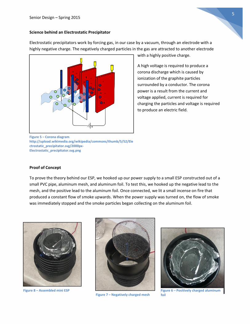
Science behind an Electrostatic Precipitator
Electrostatic precipitators work by forcing gas, in our case by a vacuum, through an electrode with a
highly negative charge. The negatively charged particles in the gas are attracted to another electrode
with a highly positive charge.
A high voltage is required to produce a
corona discharge which is caused by
ionization of the graphite particles
surrounded by a conductor. The corona
power is a result from the current and
voltage applied, current is required for
charging the particles and voltage is required
to produce an electric field.
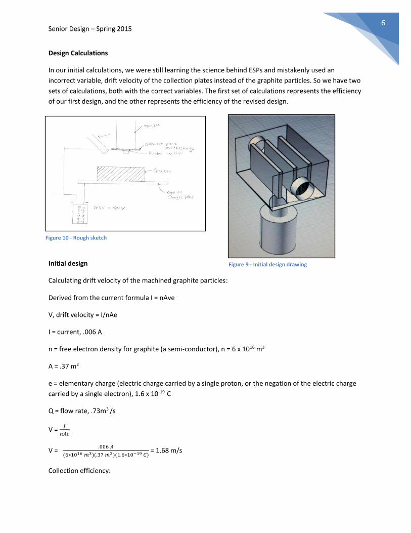
Proof of Concept
To prove the theory behind our ESP, we hooked up our power supply to a small ESP constructed out of a
small PVC pipe, aluminum mesh, and aluminum foil. To test this, we hooked up the negative lead to the
mesh, and the positive lead to the aluminum foil. Once connected, we lit a small incense on fire that
produced a constant flow of smoke upwards. When the power supply was turned on, the flow of smoke
was immediately stopped and the smoke particles began collecting on the aluminum foil.
Figure 5 – Corona diagram http://upload.wikimedia.org/wikipedia/commons/thumb/5/52/Electrostatic_precipitator.svg/2000px-Electrostatic_precipitator.svg.png
Figure 6 – Positively charged aluminum foil
Figure 8 – Assembled mini ESP Figure 7 – Negatively charged mesh
Senior Design – Spring 2015 6
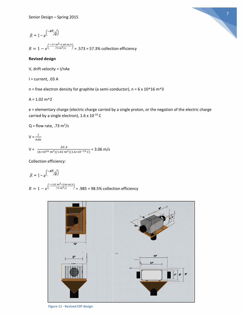
Design Calculations
In our initial calculations, we were still learning the science behind ESPs and mistakenly used an
incorrect variable, drift velocity of the collection plates instead of the graphite particles. So we have two
sets of calculations, both with the correct variables. The first set of calculations represents the efficiency
of our first design, and the other represents the efficiency of the revised design.
Initial design
Calculating drift velocity of the machined graphite particles:
Derived from the current formula I = nAve
V, drift velocity = I/nAe
I = current, .006 A
n = free electron density for graphite (a semi-conductor), n = 6 x 10¹⁶ m3
A = .37 m2
e = elementary charge (electric charge carried by a single proton, or the negation of the electric charge
carried by a single electron), 1.6 x 10⁻¹⁹ C
Q = flow rate, .73m3 /s
V = 𝐼
𝑛𝐴𝑒
V = .006 𝐴
(6∗1016 𝑚3)(.37 𝑚2)(1.6∗10−19 𝐶) = 1.68 m/s
Collection efficiency:
Figure 10 - Rough sketch
Figure 9 - Initial design drawing
Senior Design – Spring 2015 7
𝑅 = 1 − 𝑒(
−.37 𝑚2∗1.68 𝑚/𝑠
.73 𝑚3/𝑠) = .573 = 57.3% collection efficiency
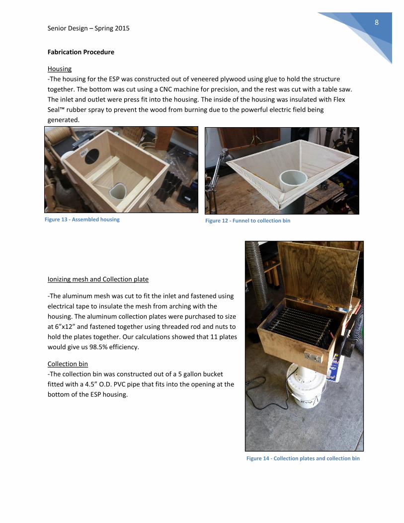
Revised design
V, drift velocity = I/nAe
I = current, .03 A
n = free electron density for graphite (a semi-conductor), n = 6 x 10^16 m^3
A = 1.02 m^2
e = elementary charge (electric charge carried by a single proton, or the negation of the electric charge
carried by a single electron), 1.6 x 10⁻¹⁹ C
Q = flow rate, .73 m3/s
V = 𝐼
𝑛𝐴𝑒
V = .03 𝐴
(6∗1016 𝑚3)(1.02 𝑚2)(1.6∗10−19 𝐶) = 3.06 m/s
Collection efficiency:
𝑅 = 1 − 𝑒(
−1.02 𝑚2∗3.06 𝑚/𝑠
.73 𝑚3/𝑠) = .985 = 98.5% collection efficiency
Figure 11 - Revised ESP design
Senior Design – Spring 2015 8
Fabrication Procedure
Housing
-The housing for the ESP was constructed out of veneered plywood using glue to hold the structure
together. The bottom was cut using a CNC machine for precision, and the rest was cut with a table saw.
The inlet and outlet were press fit into the housing. The inside of the housing was insulated with Flex
Seal™ rubber spray to prevent the wood from burning due to the powerful electric field being
generated.
Ionizing mesh and Collection plate
-The aluminum mesh was cut to fit the inlet and fastened using
electrical tape to insulate the mesh from arching with the
housing. The aluminum collection plates were purchased to size
at 6”x12” and fastened together using threaded rod and nuts to
hold the plates together. Our calculations showed that 11 plates
would give us 98.5% efficiency.
Collection bin
-The collection bin was constructed out of a 5 gallon bucket
fitted with a 4.5” O.D. PVC pipe that fits into the opening at the
bottom of the ESP housing.
Figure 13 - Assembled housing Figure 12 - Funnel to collection bin
Figure 14 - Collection plates and collection bin
Senior Design – Spring 2015 9
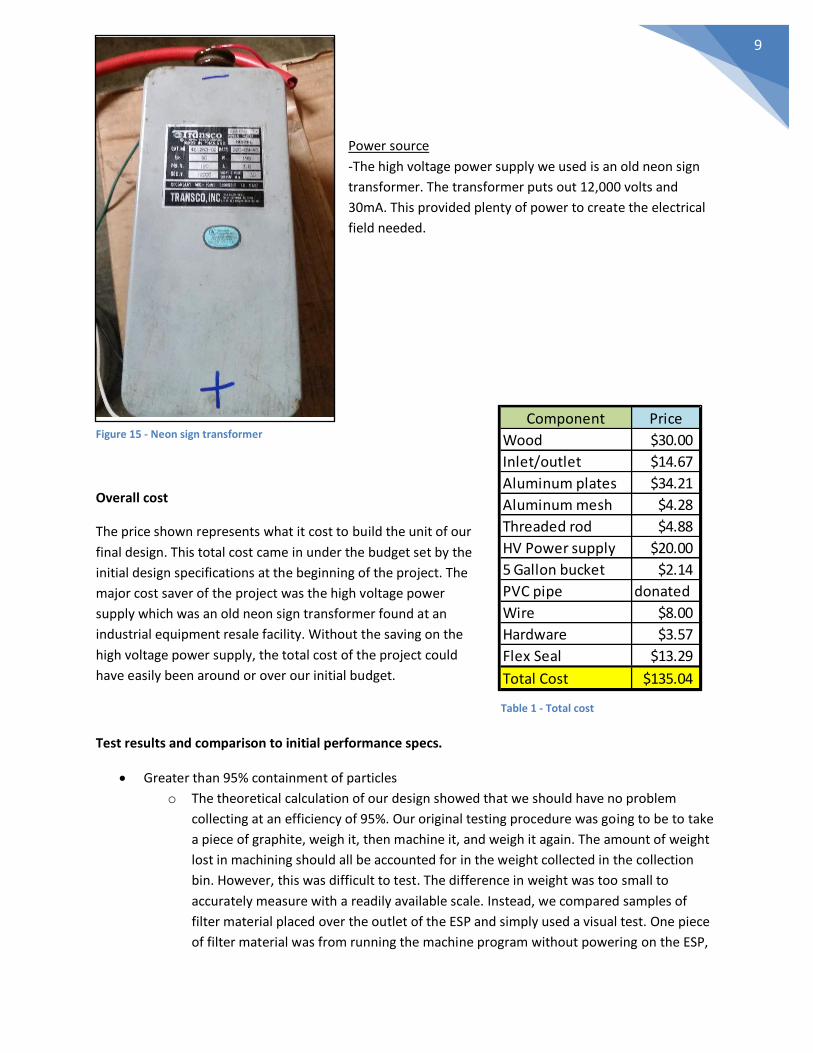
Power source
-The high voltage power supply we used is an old neon sign
transformer. The transformer puts out 12,000 volts and
30mA. This provided plenty of power to create the electrical
field needed.
Overall cost
The price shown represents what it cost to build the unit of our
final design. This total cost came in under the budget set by the
initial design specifications at the beginning of the project. The
major cost saver of the project was the high voltage power
supply which was an old neon sign transformer found at an
industrial equipment resale facility. Without the saving on the
high voltage power supply, the total cost of the project could
have easily been around or over our initial budget.
Test results and comparison to initial performance specs.
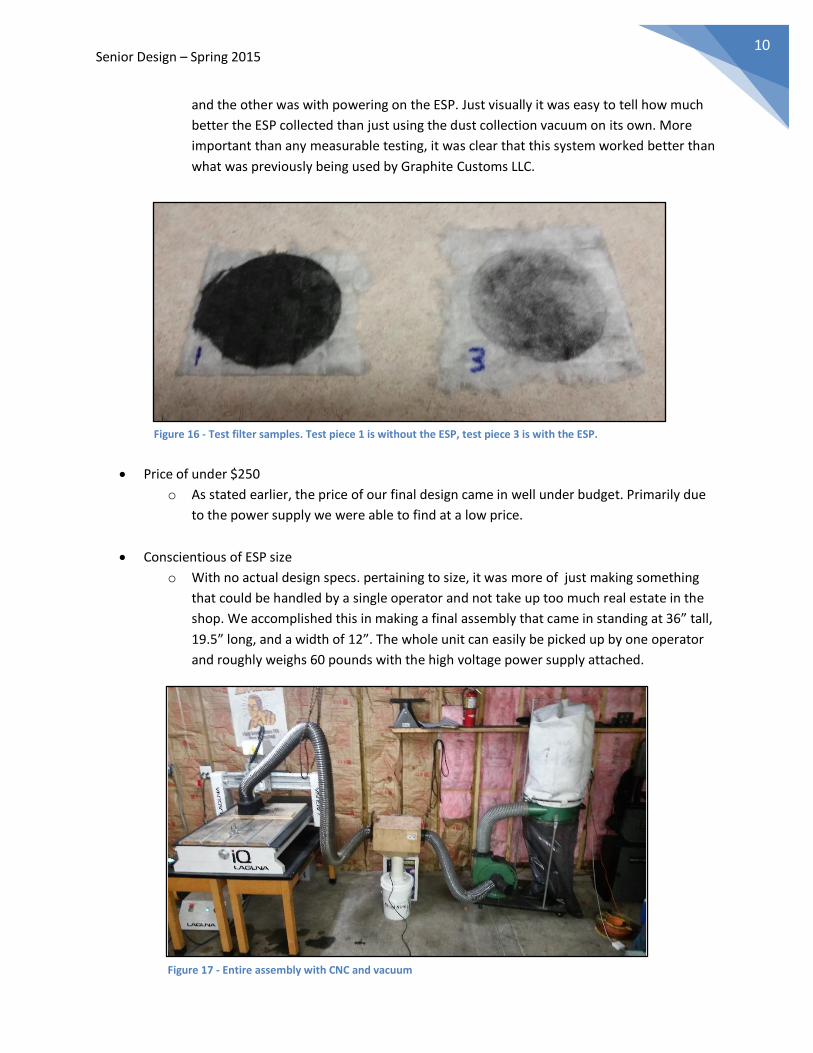
Greater than 95% containment of particles
o The theoretical calculation of our design showed that we should have no problem
collecting at an efficiency of 95%. Our original testing procedure was going to be to take
a piece of graphite, weigh it, then machine it, and weigh it again. The amount of weight
lost in machining should all be accounted for in the weight collected in the collection
bin. However, this was difficult to test. The difference in weight was too small to
accurately measure with a readily available scale. Instead, we compared samples of
filter material placed over the outlet of the ESP and simply used a visual test. One piece
of filter material was from running the machine program without powering on the ESP,
Component Price
Wood $30.00
Inlet/outlet $14.67
Aluminum plates $34.21
Aluminum mesh $4.28
Threaded rod $4.88
HV Power supply $20.00
5 Gallon bucket $2.14
PVC pipe donated
Wire $8.00
Hardware $3.57
Flex Seal $13.29
Total Cost $135.04
Figure 15 - Neon sign transformer
Table 1 - Total cost
Senior Design – Spring 2015 10
and the other was with powering on the ESP. Just visually it was easy to tell how much
better the ESP collected than just using the dust collection vacuum on its own. More
important than any measurable testing, it was clear that this system worked better than
what was previously being used by Graphite Customs LLC.
Price of under $250
o As stated earlier, the price of our final design came in well under budget. Primarily due
to the power supply we were able to find at a low price.
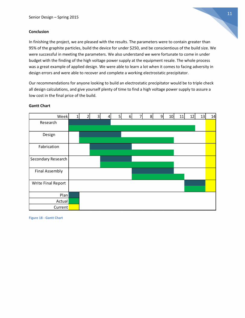
Conscientious of ESP size
o With no actual design specs. pertaining to size, it was more of just making something
that could be handled by a single operator and not take up too much real estate in the
shop. We accomplished this in making a final assembly that came in standing at 36” tall,
19.5” long, and a width of 12”. The whole unit can easily be picked up by one operator
and roughly weighs 60 pounds with the high voltage power supply attached.
Figure 16 - Test filter samples. Test piece 1 is without the ESP, test piece 3 is with the ESP.
Figure 17 - Entire assembly with CNC and vacuum
Senior Design – Spring 2015 11
Conclusion
In finishing the project, we are pleased with the results. The parameters were to contain greater than
95% of the graphite particles, build the device for under $250, and be conscientious of the build size. We
were successful in meeting the parameters. We also understand we were fortunate to come in under
budget with the finding of the high voltage power supply at the equipment resale. The whole process
was a great example of applied design. We were able to learn a lot when it comes to facing adversity in
design errors and were able to recover and complete a working electrostatic precipitator.
Our recommendations for anyone looking to build an electrostatic precipitator would be to triple check
all design calculations, and give yourself plenty of time to find a high voltage power supply to assure a
low cost in the final price of the build.
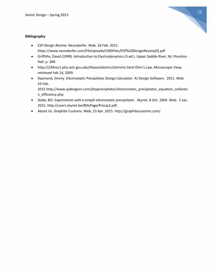
Gantt Chart
Figure 18 - Gantt Chart
Week 1 2 3 4 5 6 7 8 9 10 11 12 13 14
Research
Design
Fabrication
Secondary Research
Final Assembly
Write Final Report
Plan
Actual
Current
Senior Design – Spring 2015 12
Bibliography
ESP Design Review. Neundorfer. Web. 26 Feb. 2015.
https://www.neundorfer.com/FileUploads/CMSFiles/ESP%20DesignReview[0].pdf
Griffiths, David (1999). Introduction to Electrodynamics (3 ed.). Upper Saddle River, NJ: Prentice-
Hall. p. 289.
http://230nsc1.phy-astr.gsu.edu/hbase/electric/ohmmic.html Ohm's Law, Microscopic View,
retrieved Feb 14, 2009
Raymond, Jimmy. Electrostatic Precipitator Design Calculator. AJ Design Software. 2011. Web.
24 Feb.
2015.http://www.ajdesigner.com/phpprecipitator/electrostatic_precipitator_equation_collectio
n_efficiency.php
Slade, Bill. Experiments with a simple electrostatic precipitator. Skynet. 8 Oct. 2004. Web. 5 Jan.
2015. http://users.skynet.be/BillsPage/Precip2.pdf.
About Us. Graphite Customs. Web. 23 Apr. 2015. http://graphitecustoms.com/