Embed Size (px)
Citation preview

K. H. Wright (UAH)
T. Schneider, J. Vaughn (NASA/MSFC)
B. Hoang, V. Funderburk, F. Wong, G.Gardiner (SS/L)
11th Spacecraft Charging and Technology Conference
Albuquerque, New Mexico, USA
Sept 20 – 24, 2010
Electrostatic Discharge Test of
Multi-Junction Solar Array Coupons
after Combined Space Environmental
Exposures

11th
SCTC Albuquerque, NM Sept 20 - 24, 2010 2
Combined Environment Test Program - Outline
Traditional environmental testing of solar array coupons
consists of subjecting the coupons to a number of thermal cycles
representing the effective mission lifetime.
Our test program is more ambitious in that solar array coupons
will be subjected to a sequence of 5-year increments of combined
environmental exposure tests.
ESD → UV radiation → electron/proton particle radiation →
thermal cycling → ion thruster plume erosion
(all tests performed at the NASA/Marshall space Flight Center)
Further details of this multi-phase test program are discussed
in the poster paper entitled “Combined Space Environmental
Exposure Tests of Multi-junction GaAs/Ge Solar Array Coupons”
by Hoang et al.
11th
SCTC Albuquerque, NM Sept 20 - 24, 2010 3
Combined Environment Test Program - Outline
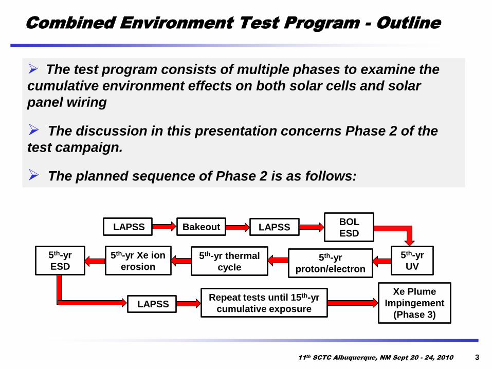
The test program consists of multiple phases to examine the
cumulative environment effects on both solar cells and solar
panel wiring
The discussion in this presentation concerns Phase 2 of the
test campaign.
The planned sequence of Phase 2 is as follows:
LAPSS Bakeout LAPSSBOL
ESD
5th-yr
UV5th-yr
proton/electron
5th-yr thermal
cycle
5th-yr Xe ion
erosion
5th-yr
ESD
Repeat tests until 15th-yr
cumulative exposure
Xe Plume
Impingement
(Phase 3)LAPSS

11th
SCTC Albuquerque, NM Sept 20 - 24, 2010 4
Test Coupon Description
4 Emcore ATJ GaAs/Ge cells: 2 strings with 2 cells/string.
Cell area = 30.49 cm2.
Coverglass - Qioptiq CMG, 100-μm thick with a single-layer MgF2
anti-reflective coating.
Each solar cell assembly (SCA) has a discrete Silicon bypass diode.
Coupon size is dictated by the limitation of the radiation facility.
3 coupons used in test program (designated as A, B, and C).
For Coupon C, this cell
is intentionally
repaired

11th
SCTC Albuquerque, NM Sept 20 - 24, 2010 5
ESD Test: Outline
ESD tests are performed at Beginning-of-Life (BOL), 5-year,
10-year, and 15-year (End-of-Life)
Uses guidelines from ISO-11221
Test Conditions:
Inverted gradient mode
Two differential string voltages: 55 V/0.55 A and 108 V/0.55 A.
Limited quantity of arcs through Phase 2 motivated by study
of SS/L GEO satellites and number of arcs (Cho et al., Number of arcs estimated on solar array of a geostationary satellite,
J. Spacecraft and Rockets, Vol. 42, No. 4, July – August, pp. 640-748, 2005.)
• Two arcs in each threshold test
• Five arcs per each differential string voltage in each ESD
test (60 total)

Electron
Flood Gun
Plasma
Source
Trek
Probe
Cryo-Shroud
Camera
Translational
And Rotational
Stage
HV Cable
Feedthrough
2-D
Stage
Test
Coupon
Faraday
Cup
11th
SCTC Albuquerque, NM Sept 20 - 24, 2010 6
Test Setup Description
Test
Rack(s)
w/circuitOscilloscopes
LabView
Data
Acquisition
VCR DVR
Control
Unit
LabView
Vacuum chamber is 2.1 m long by 1.2 m dia. with 4 cryo-pumps → P < 1x10⁻⁶ Torr

11th
SCTC Albuquerque, NM Sept 20 - 24, 2010 7
Arc Threshold Test Circuit
Vacuum Chamber
Vbias
CP3
CP4
CP5
CP6
V
11th
SCTC Albuquerque, NM Sept 20 - 24, 2010 8
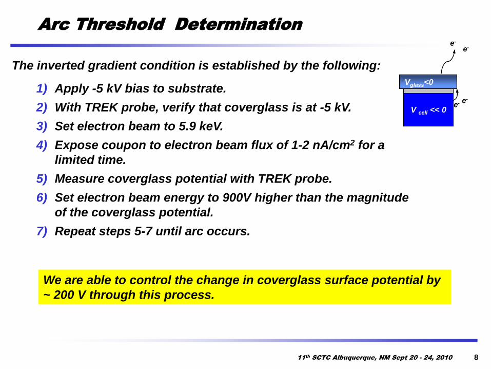
Arc Threshold Determination
The inverted gradient condition is established by the following:
1) Apply -5 kV bias to substrate.
2) With TREK probe, verify that coverglass is at -5 kV.
3) Set electron beam to 5.9 keV.
4) Expose coupon to electron beam flux of 1-2 nA/cm2 for a
limited time.
5) Measure coverglass potential with TREK probe.
6) Set electron beam energy to 900V higher than the magnitude
of the coverglass potential.
7) Repeat steps 5-7 until arc occurs.
We are able to control the change in coverglass surface potential by
~ 200 V through this process.
Vglass<0
V cell << 0e-
e-
e-
e-

0
500
1000
1500
2000
2500
3000
3500
4000
-80 -70 -60 -50 -40 -30 -20 -10 0 10 20 30
Invert
ed
Gra
die
nt
Vo
ltag
e (
V)
Coupon Temperature (C)
Coupon A, B, C
Coupon A
Coupon B
Coupon C
Linear Fit
11th
SCTC Albuquerque, NM Sept 20 - 24, 2010 9
Arc Threshold BOL Results
Avg = 2904 V
Std Dev = 378 V
Present limit for cold capability
in ESD chamber

11th
SCTC Albuquerque, NM Sept 20 - 24, 2010 10
ESD Test Circuit: Primary Arc Pulse Assumptions
Geometry of Coverglass Flashover from
the Center of the Solar Array Panel
From Hoang et al., Electrostatic discharge test with simulated coverglass flashover for multi-junction GaAs/Ge
solar array design, 35th IEEE Photovoltaic Specialists Conference, Honolulu, Hawaii, June 20–25, 2010.
Assumptions:
1) Coverglass outer surface initially uniformly charged to
Voltage (Vc) with respect to solar cell top surface, and
discharges by amount deltaV (or Vth) during flashover.
2) Flashover current for one panel is assumed to all be
collected at a single initiation site.
3) Flashover propagates in a radial surface charge sweep at
a constant velocity starting at the initial discharge point.
4) Worst-case peak current is based on complete panel
coverglass discharge resulting from a single discharge in
the center of the panel. Ccg represents the capacitance of
the panel coverglass.
5) Flashover terminates at panel edges (R1, R2 and R3) as
shown in the figure. Note that R3 ~ 2 meters.
With the assumption of constant
flashover velocity,
tvVCtI thcg
22)( Eq. (1)
I(t) = dQ/dt = d (CcgVthA)/dt
I(t) = CcgVth dA/dt
where A = πr2
I(t) = CcgVth d(πr2)/dt = 2πCcgVth r dr/dt
where v = dr/dt

11th
SCTC Albuquerque, NM Sept 20 - 24, 2010 11
ESD Test Circuit: Primary Arc Pulse Analysis
From Hoang et al., Electrostatic discharge test with simulated coverglass flashover for multi-junction GaAs/Ge
solar array design, 35th IEEE Photovoltaic Specialists Conference, Honolulu, Hawaii, June 20–25, 2010.
1) Flashover propagation velocity, ν = 104 m/s
2) Average measured primary arc threshold voltage of SS/L
ATJ array design (~ 2 kV from previous tests)
3) Calculated panel coverglass capacitance
4) Flashover time to R1, R2 and R3 per Figure on Slide 10,
based on the SS/L panel geometry
RLC circuit designed to produce waveform
that meets three parameters:
1. Peak current
2. Time to peak current
3. Total charge of the panel coverglass
From Eq. (1):
AmpstI R 4.28)( 1
(Peak current at R1 as shown in Figure on Slide 10)
SPICE model calculation compared with
measurement of MSFC ESD test circuit:

11th
SCTC Albuquerque, NM Sept 20 - 24, 2010 12
ESD Test Circuit Schematic
If needed, used for sustained arc interruption
Vacuum Chamber
Vbias
Vclamp
Rvc2
Rbp1
Rbp2
CP1
CP2
CP3
CP4
CP5
CP6
CP7
V
HV Relay
CP1AA
B
O
RL
C C
ircu
it
Byp
ass C
ircu
it
SA
S

11th
SCTC Albuquerque, NM Sept 20 - 24, 2010 13
Example of Arc: BOL
Coupon B: 108V between strings;
Temp = -69C; ΔV ~ 3200VCurrent through String-2/Cell-2
Current through String-2/Cell-1
Primary Arc CurrentNo activity detected on String-1

11th
SCTC Albuquerque, NM Sept 20 - 24, 2010 14
Arc Site Summary: BOL
A
B
C
• The count is the combination of arc
threshold and ESD tests
• Popular arc sites are cell tabs,
busbars, and feed-through bushings
• For Coupon C, arc sites favor the
reworked cell
No Temporary Sustained Arcs
detected during BOL.

11th
SCTC Albuquerque, NM Sept 20 - 24, 2010 15
5th
-year Test: Status
5th-year UV, proton/electron radiation, and thermal cycling tests
have been completed
Inspection has shown various cracks in RTV over tabs and
busbars and cracks in the grout between cells. Also, cracks on
a few of the cell coverglasses are observed.

11th
SCTC Albuquerque, NM Sept 20 - 24, 2010 16
5th
-year Test: Status (cont.)
Acquisition of a new source for use in the 5-year Xenon ion
erosion test is in work.
A slight alteration in the ESD test plan has occurred – partial ESD
testing has been performed on each coupon.
The arc threshold voltage for each coupon has changed
significantly. It is now ~ 200 V! After ion erosion is
completed, will this value change?
Two arcs at each string differential voltage (55 V and 108 V)
have been obtained on each coupon. Arc sites preferentially
remain as observed during the BOL testing.
After ion erosion is completed, three more ESD arcs will be
obtained. The RLC circuit used to simulate the primary arc
will remain unchanged from the BOL testing. However, based
on arc threshold data, do we change the RLC circuit for future
tests?

11th
SCTC Albuquerque, NM Sept 20 - 24, 2010 17
Arc at interim 5th
-year test point
Coupon B: 108V between strings;
Temp = 20 C; ΔV ~ 200V
Primary Arc Current
As shown in CP6 and CP2, no
activity detected on String-1!
Current through String-2/Cell-2
Current through String-2/Cell-1
11th
SCTC Albuquerque, NM Sept 20 - 24, 2010 18
Key Observations
Post 5th-year combined environmental exposures show hairline
cracks in the RTV adhesive grout.
Although an ESD event occurred at a string-to-string (or
parallel) gap, no Temporary (or Permanent) Sustained Arc was
observed.
The arc threshold voltage dropped by an order of magnitude after
the 5th-year combined environmental exposures.
Our present conjecture is that this is due to the effect of the
combined environmental exposures.
If this observation is true in orbit, then the ESD characteristics
of the solar array, such as flashover magnitude and arc
frequency, can change over the mission life.

11th
SCTC Albuquerque, NM Sept 20 - 24, 2010 19
Forward Work
The chamber used for the ESD testing in Phase 2 is also used for
ESD testing on another phase of the comprehensive SS/L test
campaign involving wire coupons.
Ion Erosion testing is potentially slated for this chamber as well
but will most likely be performed in a different chamber.
Scheduling conflicts are driving completion of the 5th-year ESD
testing until this fall (2010).
10th- and 15th-year ESD testing is currently planned for early and
mid 2011, respectively.
Based on our preliminary observations of our solar array
coupon characteristics, there is an apparent need for further
research in material properties as a function of combined space
environmental exposures.