Embed Size (px)
Citation preview
0102
GM 2800EA
II 2G EEx 0.24 mJ T6 (Atex 95)
Translation of the original
Operating manual
Electrostatic Air spray gunfor manual operation
with fl at or round jet nozzles
Edition 03/ 2007


3
GM 2800EA
OPERATING MANUAL
EDITION 03/ 2007 PART NO. DOC388891
Contents
1 ABOUT THESE INSTRUCTIONS 51.1 Language 51.2 Warnings, notes and symbols in these instructions 5
2 GENERAL SAFETY INSTRUCTIONS 62.1 Safety instructions for the operator 62.1.1 Electrical equipment 62.1.2 Personnel qualifi cations 62.1.3 A safe work environment 62.2 Safety instructions for personnel 62.2.1 Safe handling of WAGNER spray units. 72.2.2 Earth the unit 72.2.3 Material hoses 72.2.4 Cleaning 82.2.5 Handling hazardous liquids, varnishes and paints 82.2.6 Touching hot surfaces 82.3 Correct use 82.4 Safety-relevant information about discharges 92.5 Use in an explosion hazard area 92.5.1 Correct use 92.5.2 Explosion protection identifi cation 92.5.3 Maxi. surface temperature 92.5.4 Safety instructions 102.6 German Regulations and guidelines 10
3 PRODUCT LIABILITY AND WARRANTY 113.1 Important notes on product liability 113.2 Warranty 113.3 CE-Conformity 123.5 PTB Conformity Certifi cation 13
4 DESCRIPTION 144.1 Area of application, using in accordance with the instructions 144.1.1 What kind of spraying material can be applied 144.2 Scope of supply 154.3 Technical data 164.4 Function 174.4.1 Design of spray gun 174.4.2 Functions of the gun 174.5 Air atomizing spray process 184.5.1 Round and fl at jet 184.5.2 Round jet 184.5.3 Flat jet 184.5.4 Electrostatic effect 19
5 PREPARATION BEFORE STARTING WORK 205.1 Set up and connect 205.1.1 Typical electrostatic spraying system 205.1.2 Ventilation of the spray booth 215.1.3 Air Supply 21
4
GM 2800EA
OPERATING MANUAL
EDITION 03/ 2007 PART NO. DOC388891
5.1.4 Fluid (Paint) hoses 215.1.5 Earthing 225.2 Preparation of paint 245.2.1 Viscosity conversion table 245.3 Start-up 255.3.1 General rules for making adjustments to the spray gun 255.3.2 Preparation 255.4 Working 265.4.1 Start-up for spraying 265.4.2 Adjust the spray angle with fl at jet nozzle 275.4.3 Fitting or changing round jet nozzle 275.4.4 Changing from round jet nozzle to fl at jet nozzle 285.4.5 Fitting or changing fl at jet nozzle 28
6 MAINTENANCE 296.1 Finishing work and cleaning 30
7 TROUBLE SHOOTING AND SOLUTIONS 31
8 REPAIR WORK 338.1 Replacing the value seat 338.2 Exchange of complete valve rod 348.3 Exchange of valve rod seals 358.4 Electrode replacement 368.5 Replacing the paint hose 37
9 PRODUCT DISPOSAL 38
10 ACCESSORIES 3910.1 Nozzles EA Flat-jet 3910.1.1 Paint output measured with synthetic enamel 3910.2 EA Round jet nozzle (SUPRA) 4010.2.1 Paint output measured with synthetic enamel 4010.3 Hoses, fi ttings and electrical cables 4110.4 Special tools 4110.5 Valve seat and Valve needle head - Plastic 4110.6 Miscellaneous 41
11 SPARE PARTS CATALOGUE 4211.1 How to order spare parts? 4211.2 Spare parts list 43
Contents
5
GM 2800EA
OPERATING MANUAL
EDITION 03/ 2007 PART NO. DOC388891
1.1 LANGUAGE
1.2 WARNINGS, NOTES AND SYMBOLS IN THESE INSTRUCTIONS
1 ABOUT THESE INSTRUCTIONS
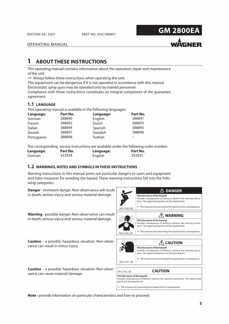
Warning instructions in this manual point out particular dangers to users and equipmentand state measures for avoiding the hazard. These warning instructions fall into the follo-wing categories:
Danger - imminent danger. Non-observance will resultin death, serious injury and serious material damage.
Warning - possible danger. Non-observance can resultin death, serious injury and serious material damage.
Caution - a possibly hazardous situation. Non-obser-vance can result in minor injury.
Note - provide information on particular characteristics and how to proceed.
Caution - a possibly hazardous situation. Non-obser-vance can cause material damage.
SIHI_0100_GB
DANGERThis line warns of the hazard!Possible consequences of failing to observe the warning instruc-tions. The signal word points out the hazard level.
The measures for preventing the hazard and its consequences.
SIHI_0103_GB
WARNINGThis line warns of the hazard!Possible consequences of failing to observe the warning instruc-tions. The signal word points out the hazard level.
The measures for preventing the hazard and its consequences.
SIHI_0101_GB
CAUTIONThis line warns of the hazard!Possible consequences of failing to observe the warning instruc-tions. The signal word points out the hazard level.
The measures for preventing the hazard and its consequences.
SIHI_0102_GB CAUTIONThis line warns of the hazard!Possible consequences of failing to observe the warning instructions. The signal wordpoints out the hazard level.
The measures for preventing the hazard and its consequences.
388890 388891388892 388893388894 388895388897 388896388898 --
353934 353935
The corresponding service instructions are available under the following order number:Language: Part No. Language: Part No.German English
6
GM 2800EA
OPERATING MANUAL
EDITION 03/ 2007 PART NO. DOC388891
2.1 SAFETY INSTRUCTIONS FOR THE OPERATOR
2.1.1 ELECTRICAL EQUIPMENT
2.1.2 PERSONNEL QUALIFICATIONS
2.1.3 A SAFE WORK ENVIRONMENT
2.2 SAFETY INSTRUCTIONS FOR PERSONNEL
2 GENERAL SAFETY INSTRUCTIONS
7
GM 2800EA
OPERATING MANUAL
EDITION 03/ 2007 PART NO. DOC388891
2.2.2 EARTH THE UNIT
2.2.3 MATERIAL HOSES
2.2.1 SAFE HANDLING OF WAGNER SPRAY UNITS.
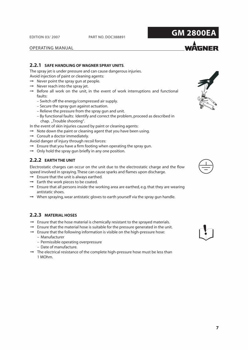
The spray jet is under pressure and can cause dangerous injuries.Avoid injection of paint or cleaning agents:
Never point the spray gun at people.Never reach into the spray jet. Before all work on the unit, in the event of work interruptions and functionalfaults:– Switch off the energy/compressed air supply.– Secure the spray gun against actuation.– Relieve the pressure from the spray gun and unit. – By functional faults: Identify and correct the problem, proceed as described in
chap. „Trouble shooting“.In the event of skin injuries caused by paint or cleaning agents:
Note down the paint or cleaning agent that you have been using.Consult a doctor immediately.
Avoid danger of injury through recoil forces:Ensure that you have a firm footing when operating the spray gun. Only hold the spray gun briefly in any one position.
Electrostatic charges can occur on the unit due to the electrostatic charge and the flowspeed involved in spraying.These can cause sparks and flames upon discharge.
Ensure that the unit is always earthed.Earth the work pieces to be coated.Ensure that all persons inside the working area are earthed, e.g. that they are wearingantistatic shoes.When spraying, wear antistatic gloves to earth yourself via the spray gun handle.
8
GM 2800EA
OPERATING MANUAL
EDITION 03/ 2007 PART NO. DOC388891
2.2.5 HANDLING HAZARDOUS LIQUIDS, VARNISHES AND PAINTS
2.2.6 TOUCHING HOT SURFACES
2.3 CORRECT USE
2.2.4 CLEANING
9
GM 2800EA
OPERATING MANUAL
EDITION 03/ 2007 PART NO. DOC388891
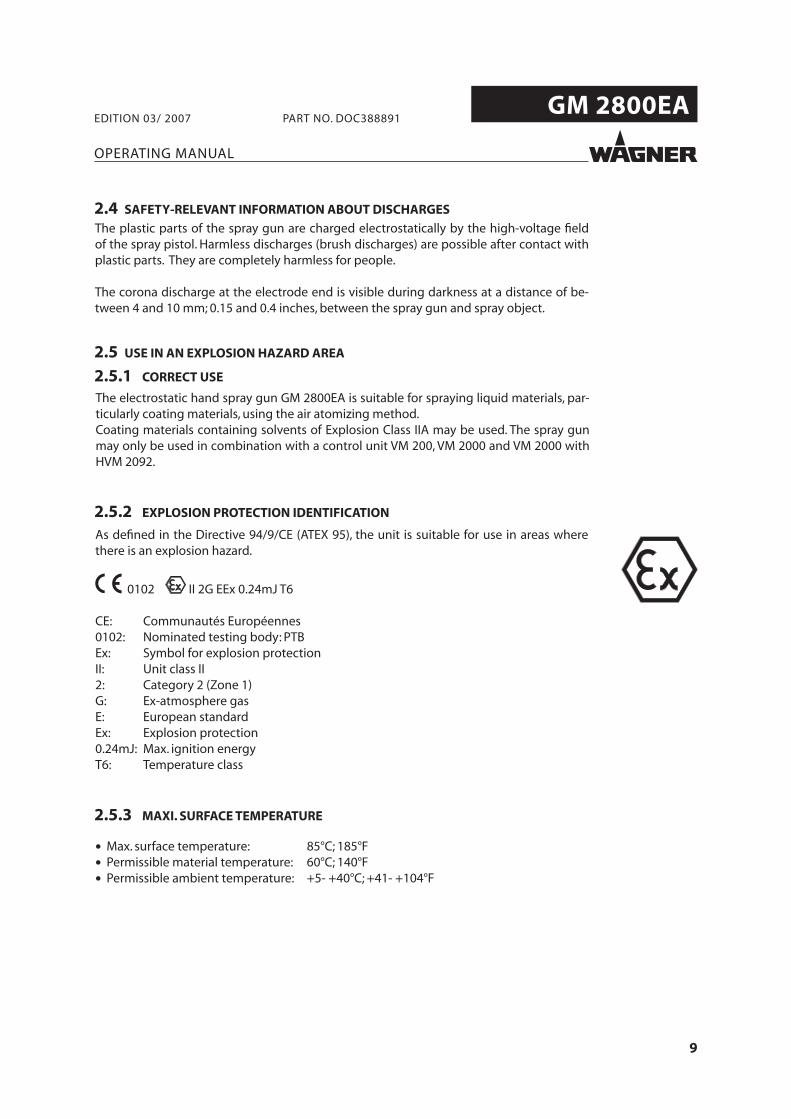
2.5.2 EXPLOSION PROTECTION IDENTIFICATION
2.5 USE IN AN EXPLOSION HAZARD AREA
2.5.1 CORRECT USE
2.5.3 MAXI. SURFACE TEMPERATURE
2.4 SAFETY-RELEVANT INFORMATION ABOUT DISCHARGES
The plastic parts of the spray gun are charged electrostatically by the high-voltage fieldof the spray pistol. Harmless discharges (brush discharges) are possible after contact withplastic parts. They are completely harmless for people.
The corona discharge at the electrode end is visible during darkness at a distance of be-tween 4 and 10 mm; 0.15 and 0.4 inches, between the spray gun and spray object.
10
GM 2800EA
OPERATING MANUAL
EDITION 03/ 2007 PART NO. DOC388891
2.5.4 SAFETY INSTRUCTIONS
2.6 GERMAN REGULATIONS AND GUIDELINES
a) BGV A2 Electrical units and equipmentb) BGR 500 Part 2, Chap. 2.36 Working with liquid ejection devicesc) BGR 500 Part 2, Chap. 2.29 Using coating materialsd) CHV 9 Regulations on flammable liquidse) CHV 11 Regulations on electrical equipment in Ex areasf ) BGR 104 Explosion protection rulesg) BGR 132 Avoiding ignition risksh) BGR 180 Setting up for cleaning with solvents for cleaning workpieces with
solventsi) ZH 1/406 Guidelines for liquid ejection devicesj) BGI 740 Painting rooms and equipmentk) BGI 764 Electrostatic coating
Note: All titles can be ordered from Heymanns Publishing House in Cologne or downloadfrom Internet.
11
GM 2800EA
OPERATING MANUAL
EDITION 03/ 2007 PART NO. DOC388891
3 PRODUCT LIABILITY AND WARRANTY
3.1 IMPORTANT NOTES ON PRODUCT LIABILITY
3.2 WARRANTY
12
GM 2800EA
OPERATING MANUAL
EDITION 03/ 2007 PART NO. DOC388891
3.3 CE-CONFORMITY
179780
CE Certificate of ConformityThe certificate is enclosed with this product.The certificate of conformity can be reorderedfrom your WAGNER representative, quoting the product and serial number.
Part number:
Herewith we declare that the supplied version of
179037 Spray gun GM 2800EA
179047 Spray gun GM 2800EA Special lengths
Complies with the following guidelines: 73/23/EWG 89/336/EWG 92/31/EWG 93/68/EWG 98/37/EG 94/9/EG
Applied standards, in particular: EN 292-1 EN 60204-1 EN 292-2 EN 61000-4-2 EN 1050 EN 61000-4-4 EN 1127-1 EN 61000-4-6 EN 1953 EN 61000-4-11 EN 50014 EN 61000-6-1 EN 50050 EN 61000-6-2 EN 55011 EN 61000-6-3 EN 55022 EN 61000-6-4
Applied national technical standards and specifi cations, in particular: See chapter 2.6
Marking:
0102 II 2G EEx 0.24 mJ T6 (Atex 95)
13
GM 2800EA
OPERATING MANUAL
EDITION 03/ 2007 PART NO. DOC388891
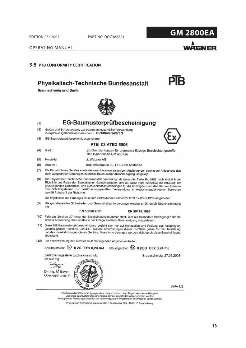
3.5 PTB CONFORMITY CERTIFICATION
14
GM 2800EA
OPERATING MANUAL
EDITION 03/ 2007 PART NO. DOC388891
4 DESCRIPTION
4.1 AREA OF APPLICATION, USING IN ACCORDANCE WITH THE INSTRUCTIONS
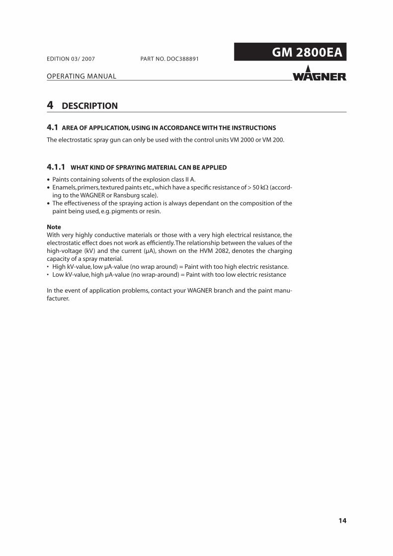
The electrostatic spray gun can only be used with the control units VM 2000 or VM 200.
4.1.1 WHAT KIND OF SPRAYING MATERIAL CAN BE APPLIED
• Paints containing solvents of the explosion class II A.
• Enamels, primers, textured paints etc., which have a specifi c resistance of > 50 kΩ (accord-ing to the WAGNER or Ransburg scale).
• The effectiveness of the spraying action is always dependant on the composition of the paint being used, e.g. pigments or resin.
NoteWith very highly conductive materials or those with a very high electrical resistance, the electrostatic effect does not work as effi ciently. The relationship between the values of the high-voltage (kV) and the current (µA), shown on the HVM 2082, denotes the charging capacity of a spray material. • High kV-value, low µA-value (no wrap around) = Paint with too high electric resistance. • Low kV-value, high µA-value (no wrap-around) = Paint with too low electric resistance
In the event of application problems, contact your WAGNER branch and the paint manu-facturer.
15
GM 2800EA
OPERATING MANUAL
EDITION 03/ 2007 PART NO. DOC388891
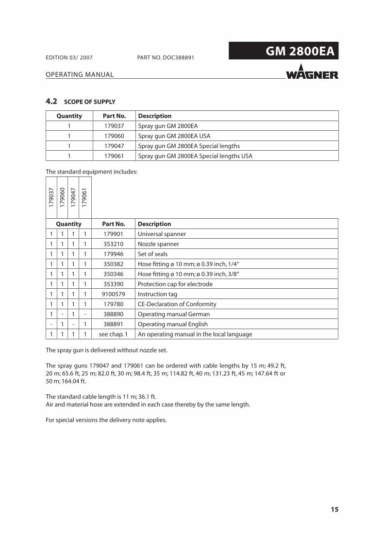
4.2 SCOPE OF SUPPLY
Quantity Part No. Description
1 179037 Spray gun GM 2800EA
1 179060 Spray gun GM 2800EA USA
1 179047 Spray gun GM 2800EA Special lengths
1 179061 Spray gun GM 2800EA Special lengths USA
The standard equipment includes:
1790
37
1790
60
1790
47
1790
61
Quantity Part No. Description
1 1 1 1 179901 Universal spanner
1 1 1 1 353210 Nozzle spanner
1 1 1 1 179946 Set of seals
1 1 1 1 350382 Hose fi tting ø 10 mm; ø 0.39 inch, 1/4“
1 1 1 1 350346 Hose fi tting ø 10 mm; ø 0.39 inch, 3/8“
1 1 1 1 353390 Protection cap for electrode
1 1 1 1 9100579 Instruction tag
1 1 1 1 179780 CE-Declaration of Conformity
1 - 1 - 388890 Operating manual German
- 1 - 1 388891 Operating manual English
1 1 1 1 see chap. 1 An operating manual in the local language
The spray gun is delivered without nozzle set.
The spray guns 179047 and 179061 can be ordered with cable lengths by 15 m; 49.2 ft, 20 m; 65.6 ft, 25 m; 82.0 ft, 30 m; 98.4 ft, 35 m; 114.82 ft, 40 m; 131.23 ft, 45 m; 147.64 ft or 50 m; 164.04 ft.
The standard cable length is 11 m; 36.1 ft. Air and material hose are extended in each case thereby by the same length.
For special versions the delivery note applies.
16
GM 2800EA
355 mm; 13.98 inch
255
mm
; 10.
04 in
ch
B_00087
OPERATING MANUAL
EDITION 03/ 2007 PART NO. DOC388891
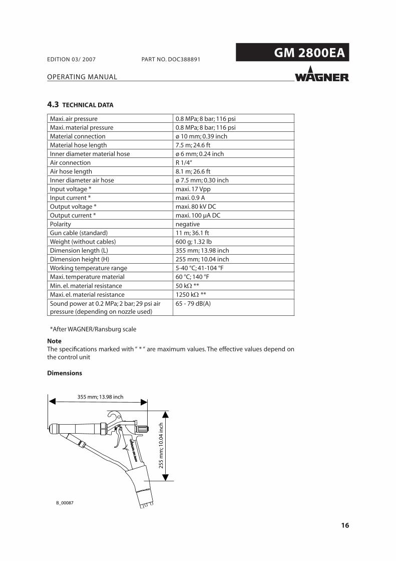
4.3 TECHNICAL DATA
Maxi. air pressure 0.8 MPa; 8 bar; 116 psiMaxi. material pressure 0.8 MPa; 8 bar; 116 psiMaterial connection ø 10 mm; 0.39 inchMaterial hose length 7.5 m; 24.6 ftInner diameter material hose ø 6 mm; 0.24 inchAir connection R 1/4“Air hose length 8.1 m; 26.6 ftInner diameter air hose ø 7.5 mm; 0.30 inchInput voltage * maxi. 17 VppInput current * maxi. 0.9 AOutput voltage * maxi. 80 kV DCOutput current * maxi. 100 µA DCPolarity negativeGun cable (standard) 11 m; 36.1 ftWeight (without cables) 600 g; 1.32 lbDimension length (L) 355 mm; 13.98 inchDimension height (H) 255 mm; 10.04 inchWorking temperature range 5-40 °C; 41-104 °FMaxi. temperature material 60 °C; 140 °F
Min. el. material resistance 50 kΩ **Maxi. el. material resistance 1250 kΩ **Sound power at 0.2 MPa; 2 bar; 29 psi air pressure (depending on nozzle used)
65 - 79 dB(A)
*After WAGNER/Ransburg scale
NoteThe specifi cations marked with “ * “ are maximum values. The effective values depend on the control unit
Dimensions
17
GM 2800EA
E
G
H
I
F
A B
J
L
M
K
N
D
C
B_00163
OPERATING MANUAL
EDITION 03/ 2007 PART NO. DOC388891
4.4 FUNCTION
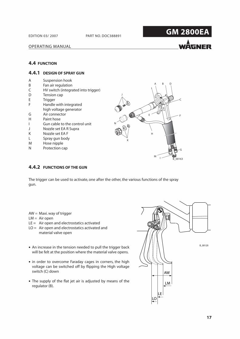
4.4.1 DESIGN OF SPRAY GUN
A Suspension hookB Fan air regulationC HV switch (integrated into trigger)D Tension capE TriggerF Handle with integrated high voltage generatorG Air connectorH Paint hoseI Gun cable to the control unitJ Nozzle set EA R SupraK Nozzle set EA FL Spray gun bodyM Hose nippleN Protection cap
4.4.2 FUNCTIONS OF THE GUN
The trigger can be used to activate, one after the other, the various functions of the spray gun.
AW = Maxi. way of triggerLM = Air openLE = Air open and electrostatics activatedLO = Air open and electrostatics activated and material valve open
• An increase in the tension needed to pull the trigger back will be felt at the position where the material valve opens.
• in order to overcome Faraday cages in corners, the high voltage can be switched off by fl ipping the High voltage switch (C) down
• The supply of the fl at jet air is adjusted by means of the regulator (B).
18
GM 2800EA
OPERATING MANUAL
EDITION 03/ 2007 PART NO. DOC388891
4.5 AIR ATOMIZING SPRAY PROCESS
4.5.1 ROUND AND FLAT JET
In this process, the material (paint) is fed to the nozzle with low pressure at approx. 0.05-0.2 MPa; 0.5-2 bar; 7-29 psi. The atomizing air at approx. 0.25-0.4 MPa; 2.5-4 bar; 36-58 psi produces a soft jet, which largely eliminates the problem of overlapping boundaries.
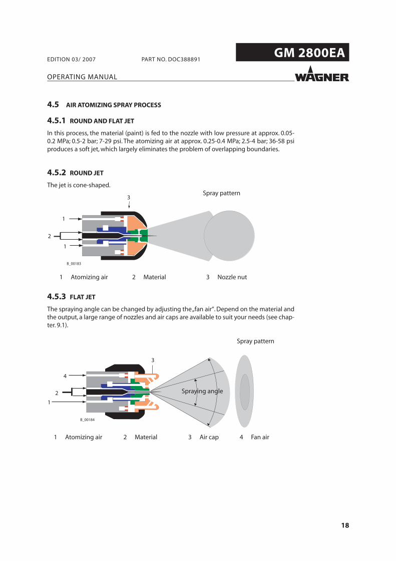
4.5.2 ROUND JET
The jet is cone-shaped.
4.5.3 FLAT JET
The spraying angle can be changed by adjusting the „fan air“. Depend on the material and the output, a large range of nozzles and air caps are available to suit your needs (see chap-ter. 9.1).
1 Atomizing air 2 Material 3 Nozzle nut
Spray pattern
1 Atomizing air 4 Fan air
Spraying angle
2 Material 3 Air cap
Spray pattern
19
GM 2800EA
OPERATING MANUAL
EDITION 03/ 2007 PART NO. DOC388891
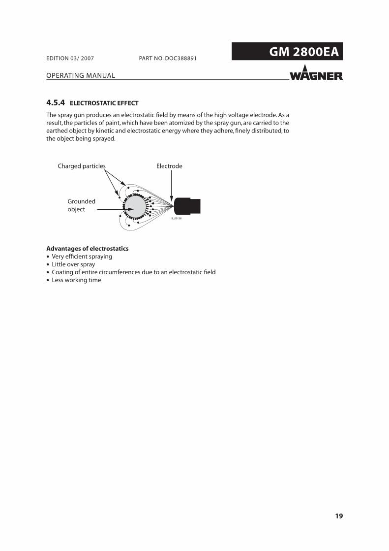
4.5.4 ELECTROSTATIC EFFECT
The spray gun produces an electrostatic fi eld by means of the high voltage electrode. As a result, the particles of paint, which have been atomized by the spray gun, are carried to the earthed object by kinetic and electrostatic energy where they adhere, fi nely distributed, to the object being sprayed.
ElectrodeCharged particles
Grounded object
Advantages of electrostatics
• Very effi cient spraying
• Little over spray
• Coating of entire circumferences due to an electrostatic fi eld
• Less working time
20
GM 2800EA
OPERATING MANUAL
EDITION 03/ 2007 PART NO. DOC388891
5 PREPARATION BEFORE STARTING WORK
5.1 SET UP AND CONNECT
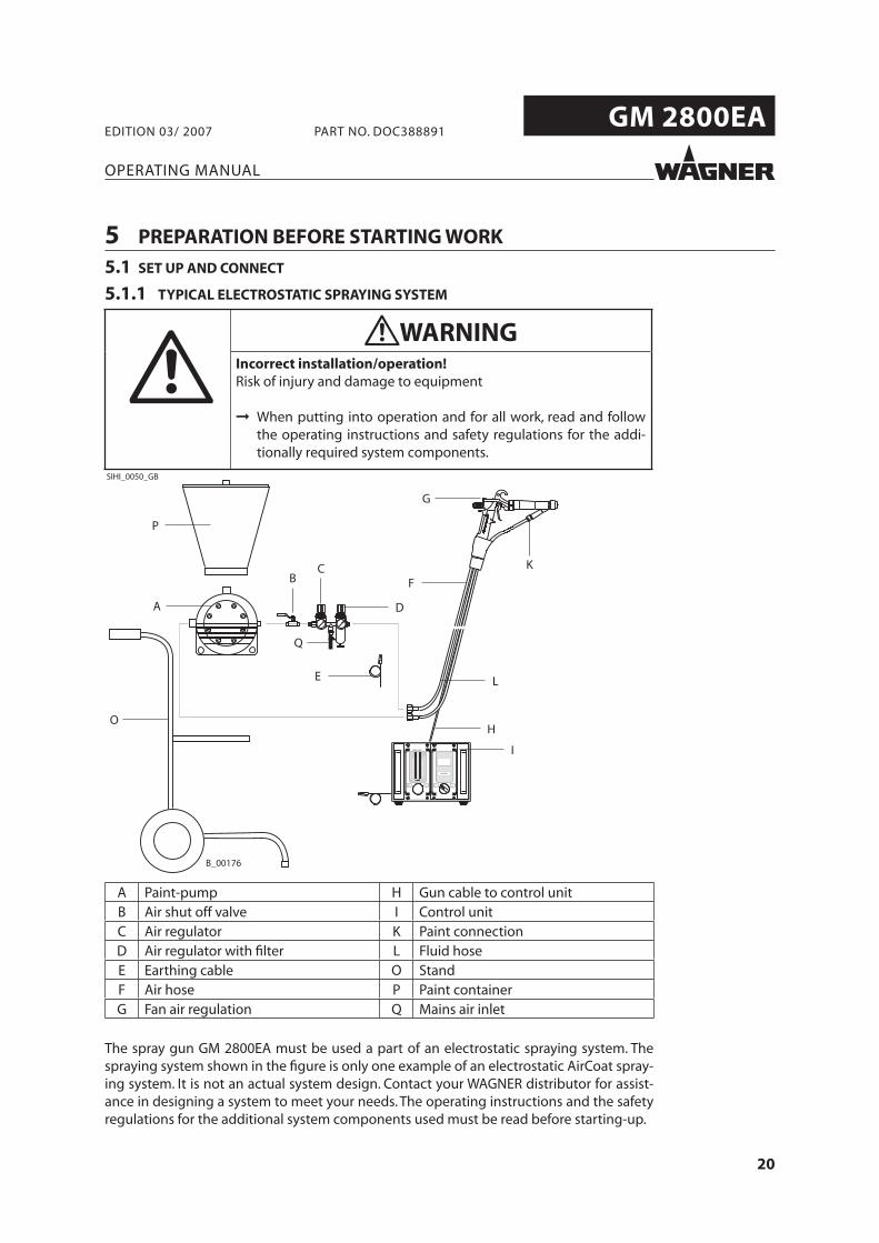
A Paint-pump H Gun cable to control unitB Air shut off valve I Control unitC Air regulator K Paint connectionD Air regulator with fi lter L Fluid hoseE Earthing cable O StandF Air hose P Paint containerG Fan air regulation Q Mains air inlet
The spray gun GM 2800EA must be used a part of an electrostatic spraying system. The spraying system shown in the fi gure is only one example of an electrostatic AirCoat spray-ing system. It is not an actual system design. Contact your WAGNER distributor for assist-ance in designing a system to meet your needs. The operating instructions and the safety regulations for the additional system components used must be read before starting-up.
5.1.1 TYPICAL ELECTROSTATIC SPRAYING SYSTEM
WARNINGIncorrect installation/operation!Risk of injury and damage to equipment
When putting into operation and for all work, read and followthe operating instructions and safety regulations for the addi-tionally required system components.
SIHI_0050_GB
21
GM 2800EA
OPERATING MANUAL
EDITION 03/ 2007 PART NO. DOC388891
5.1.2 VENTILATION OF THE SPRAY BOOTH
5.1.3 AIR SUPPLY
The use of an air fi lter with the air regulator (D) ensures that only dry, clean atomising air gets into the spray gun. Dirt and moisture in the atomising air reduce the spraying quality and the appearance of the fi nished piece.
5.1.4 FLUID (PAINT) HOSES
WARNINGToxic and/or flammable vapor mixtures!Risk of poisoning and burns
Operate the unit in a spraying booth approved for the workingmaterials.-or-Operate the unit on an appropriate spraying wall with the venti-lation (extraction) switched on. Observe national and local regulations for the outgoing airspeed.
SIHI_0028_GB
CAUTIONImpurities in the spraying system!Spray gun blockage, materials harden in the spraying system
Flush the spray gun and paint supply with a suitable cleaning agent.
SIHI_0001_GB
SIHI_0029_GB
DANGERBursting hose, bursting threaded joints!Danger to life from injection of material
Ensure that the hose material is chemically resistant.Ensure that the spray gun, threaded joints and material hosebetween the unit and the spray gun is suitable for the pressuregenerated in the unit. Ensure that the following information can be seen on the high-pressure hose: - Manufacturer- Permissible operating pressure- Date of manufacture.
22
GM 2800EA
OPERATING MANUAL
EDITION 03/ 2007 PART NO. DOC388891
5.1.5 EARTHING
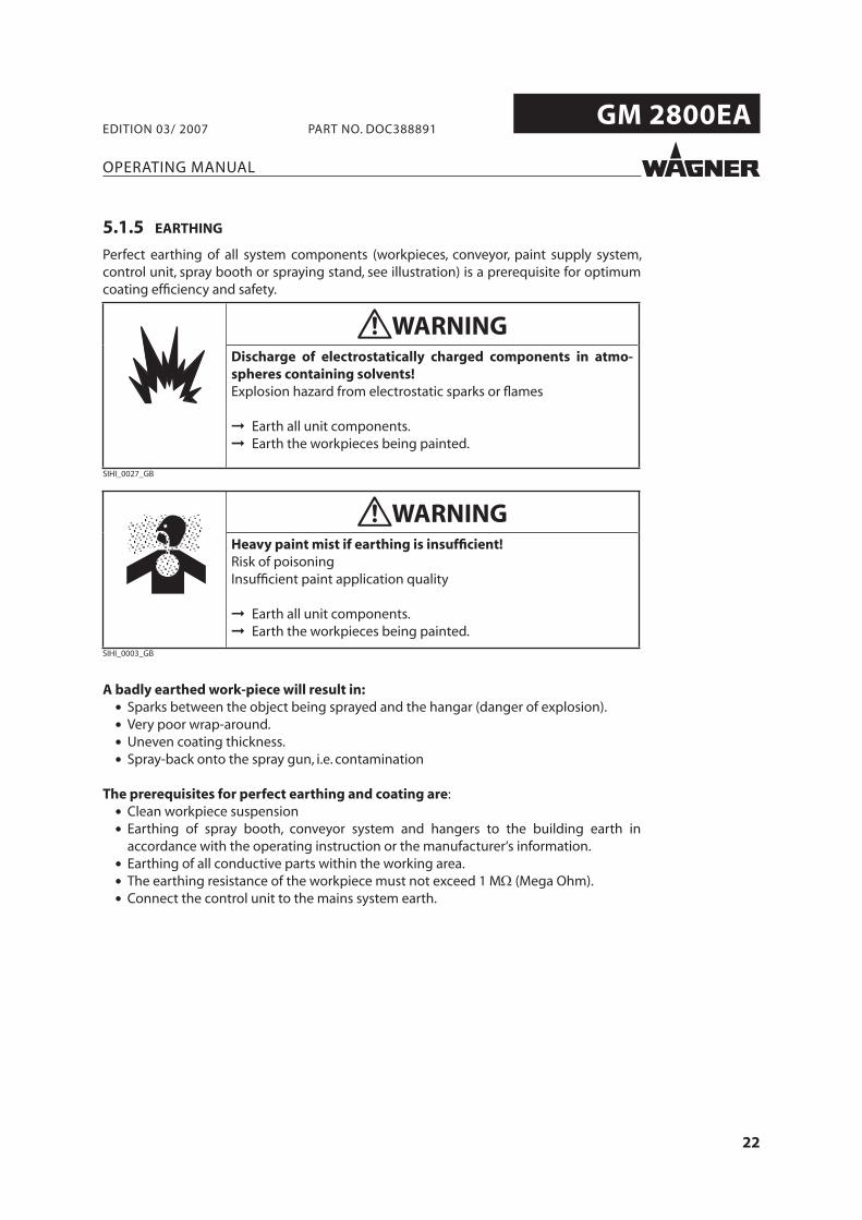
Perfect earthing of all system components (workpieces, conveyor, paint supply system, control unit, spray booth or spraying stand, see illustration) is a prerequisite for optimum coating effi ciency and safety.
A badly earthed work-piece will result in: • Sparks between the object being sprayed and the hangar (danger of explosion). • Very poor wrap-around. • Uneven coating thickness. • Spray-back onto the spray gun, i.e. contamination
The prerequisites for perfect earthing and coating are: • Clean workpiece suspension • Earthing of spray booth, conveyor system and hangers to the building earth in
accordance with the operating instruction or the manufacturer‘s information. • Earthing of all conductive parts within the working area. • The earthing resistance of the workpiece must not exceed 1 MΩ (Mega Ohm). • Connect the control unit to the mains system earth.
WARNINGDischarge of electrostatically charged components in atmo-spheres containing solvents!Explosion hazard from electrostatic sparks or flames
Earth all unit components.Earth the workpieces being painted.
SIHI_0027_GB
WARNINGHeavy paint mist if earthing is insufficient!Risk of poisoningInsufficient paint application quality
Earth all unit components.Earth the workpieces being painted.
SIHI_0003_GB
23
GM 2800EA
OPERATING MANUAL
EDITION 03/ 2007 PART NO. DOC388891
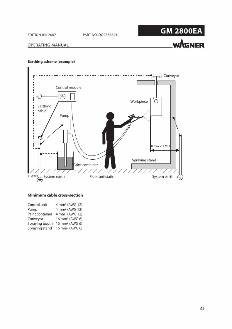
Earthing scheme (example)
Minimum cable cross-section
Control unit 4 mm² (AWG 12)Pump 4 mm² (AWG 12)Paint container 4 mm² (AWG 12)Conveyor 16 mm² (AWG 6)Spraying booth 16 mm² (AWG 6)Spraying stand 16 mm² (AWG 6)
Conveyor
Floor, antistatic
Pump
Paint containerSpraying stand
Earthingcable
Control module
System earth System earth
Workpiece
24
GM 2800EA
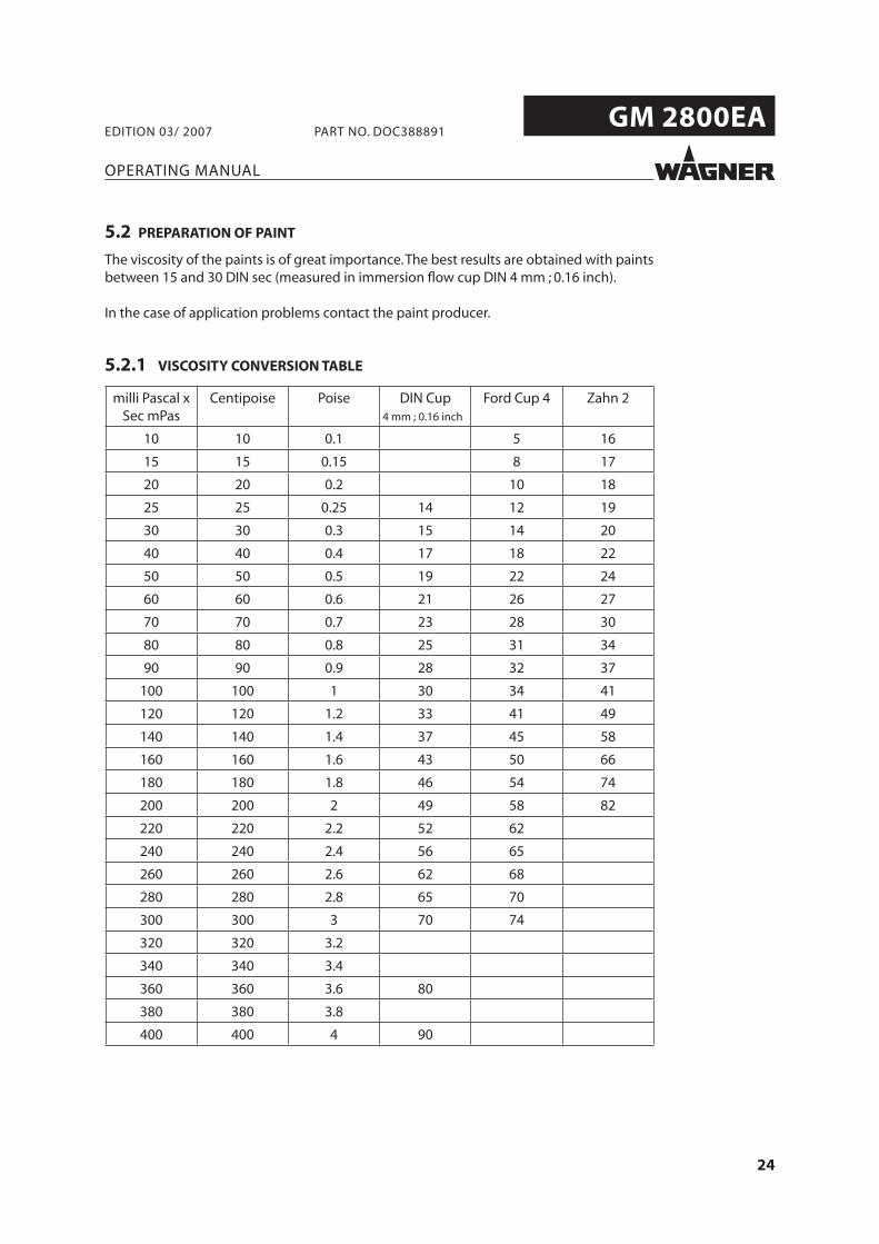
milli Pascal x Sec mPas
Centipoise Poise DIN Cup4 mm ; 0.16 inch
Ford Cup 4 Zahn 2
10 10 0.1 5 16
15 15 0.15 8 17
20 20 0.2 10 18
25 25 0.25 14 12 19
30 30 0.3 15 14 20
40 40 0.4 17 18 22
50 50 0.5 19 22 24
60 60 0.6 21 26 27
70 70 0.7 23 28 30
80 80 0.8 25 31 34
90 90 0.9 28 32 37
100 100 1 30 34 41
120 120 1.2 33 41 49
140 140 1.4 37 45 58
160 160 1.6 43 50 66
180 180 1.8 46 54 74
200 200 2 49 58 82
220 220 2.2 52 62
240 240 2.4 56 65
260 260 2.6 62 68
280 280 2.8 65 70
300 300 3 70 74
320 320 3.2
340 340 3.4
360 360 3.6 80
380 380 3.8
400 400 4 90
OPERATING MANUAL
EDITION 03/ 2007 PART NO. DOC388891
5.2 PREPARATION OF PAINT
The viscosity of the paints is of great importance. The best results are obtained with paints between 15 and 30 DIN sec (measured in immersion fl ow cup DIN 4 mm ; 0.16 inch).
In the case of application problems contact the paint producer.
5.2.1 VISCOSITY CONVERSION TABLE
25
GM 2800EA
OPERATING MANUAL
EDITION 03/ 2007 PART NO. DOC388891
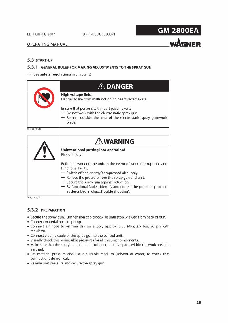
5.3.2 PREPARATION
• Secure the spray gun. Turn tension cap clockwise until stop (viewed from back of gun).
• Connect material hose to pump.
• Connect air hose to oil free, dry air supply approx. 0.25 MPa; 2.5 bar; 36 psi with regulator.
• Connect electric cable of the spray gun to the control unit.
• Visually check the permissible pressures for all the unit components.
• Make sure that the spraying unit and all other conductive parts within the work area are earthed.
• Set material pressure and use a suitable medium (solvent or water) to check that connections do not leak.
• Relieve unit pressure and secure the spray gun.
5.3 START-UP
5.3.1 GENERAL RULES FOR MAKING ADJUSTMENTS TO THE SPRAY GUN
➞ See safety regulations in chapter 2.
DANGERHigh voltage field! Danger to life from malfunctioning heart pacemakers
Ensure that persons with heart pacemakers:Do not work with the electrostatic spray gun. Remain outside the area of the electrostatic spray gun/work-piece.
SIHI_0049_GB
SIHI_0065_GB
WARNINGUnintentional putting into operation!Risk of injury
Before all work on the unit, in the event of work interruptions andfunctional faults:
Switch off the energy/compressed air supply.Relieve the pressure from the spray gun and unit. Secure the spray gun against actuation.By functional faults: Identify and correct the problem, proceedas described in chap„Trouble shooting“.
26
GM 2800EA
OPERATING MANUAL
EDITION 03/ 2007 PART NO. DOC388891
5.4.1 START-UP FOR SPRAYING
1. Switch on the material supply adjust from approx. 0.05-0.15 MPa; 0.5-1.5 bar; 7-22 psi and the control unit.
2. Unlock spray gun with tension cap.3. Spray on a test object (press the trigger).4. Adjust the spray pressure and atomizing air in accordance with the nozzle and object.
NoteThe paint output volume can be changed by:
• Changing the material pressure. or
• Fitting another fl at jet nozzle. See accessories.
5.4 WORKING
27
GM 2800EA
A
OPERATING MANUAL
EDITION 03/ 2007 PART NO. DOC388891
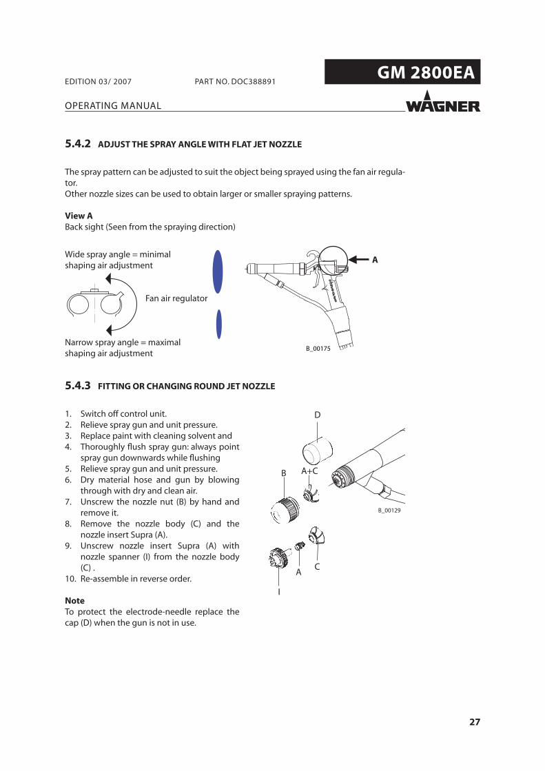
5.4.2 ADJUST THE SPRAY ANGLE WITH FLAT JET NOZZLE
The spray pattern can be adjusted to suit the object being sprayed using the fan air regula-tor.Other nozzle sizes can be used to obtain larger or smaller spraying patterns.
View ABack sight (Seen from the spraying direction)
Fan air regulator
Wide spray angle = minimal shaping air adjustment
Narrow spray angle = maximal shaping air adjustment
5.4.3 FITTING OR CHANGING ROUND JET NOZZLE
1. Switch off control unit.2. Relieve spray gun and unit pressure.3. Replace paint with cleaning solvent and4. Thoroughly fl ush spray gun: always point
spray gun downwards while fl ushing5. Relieve spray gun and unit pressure.6. Dry material hose and gun by blowing
through with dry and clean air.7. Unscrew the nozzle nut (B) by hand and
remove it.8. Remove the nozzle body (C) and the
nozzle insert Supra (A).9. Unscrew nozzle insert Supra (A) with
nozzle spanner (I) from the nozzle body (C) .
10. Re-assemble in reverse order.
NoteTo protect the electrode-needle replace the cap (D) when the gun is not in use.
28
GM 2800EA
OPERATING MANUAL
EDITION 03/ 2007 PART NO. DOC388891
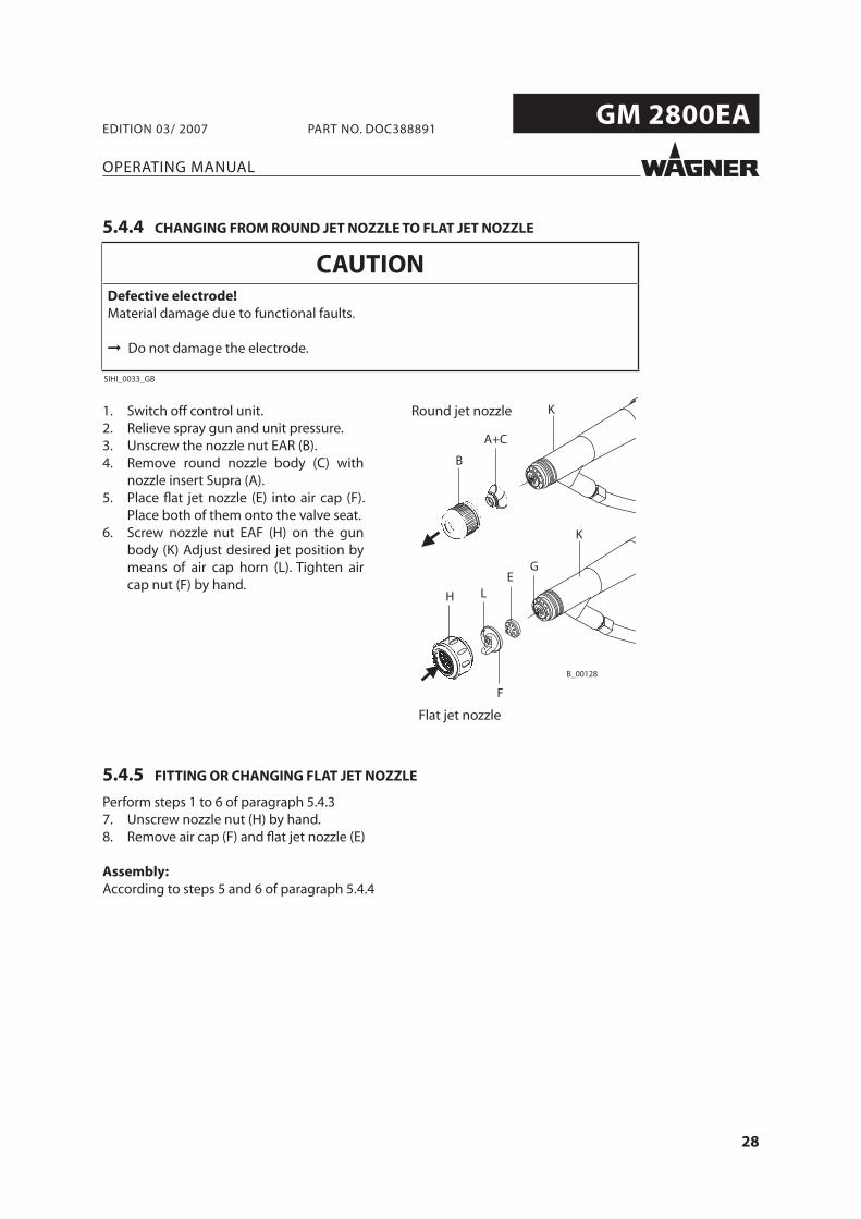
5.4.4 CHANGING FROM ROUND JET NOZZLE TO FLAT JET NOZZLE
1. Switch off control unit.2. Relieve spray gun and unit pressure.3. Unscrew the nozzle nut EAR (B).4. Remove round nozzle body (C) with
nozzle insert Supra (A).5. Place fl at jet nozzle (E) into air cap (F).
Place both of them onto the valve seat.6. Screw nozzle nut EAF (H) on the gun
body (K) Adjust desired jet position by means of air cap horn (L). Tighten air cap nut (F) by hand.
5.4.5 FITTING OR CHANGING FLAT JET NOZZLE
Perform steps 1 to 6 of paragraph 5.4.37. Unscrew nozzle nut (H) by hand.8. Remove air cap (F) and fl at jet nozzle (E)
Assembly:According to steps 5 and 6 of paragraph 5.4.4
Round jet nozzle
Flat jet nozzle
29
GM 2800EA
OPERATING MANUAL
EDITION 03/ 2007 PART NO. DOC388891
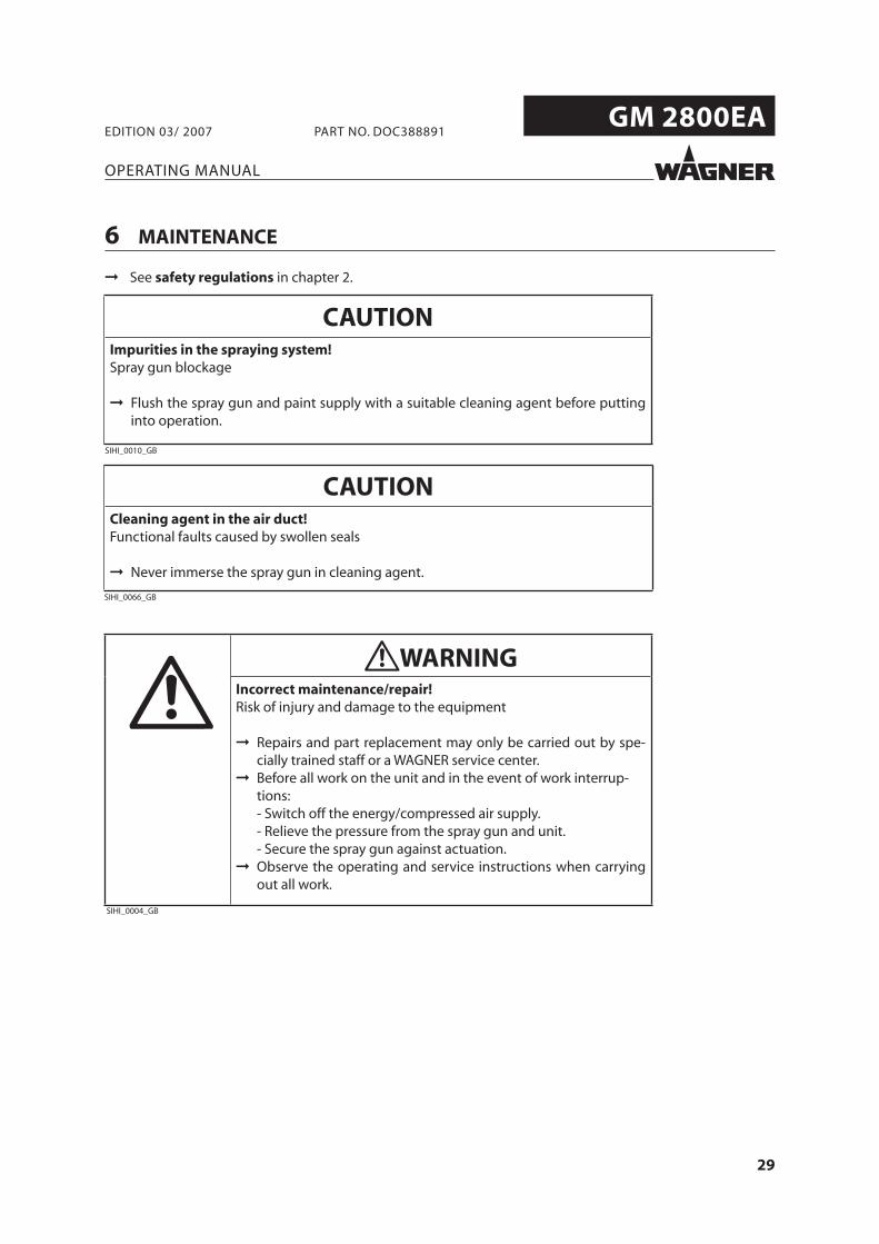
6 MAINTENANCE
➞ See safety regulations in chapter 2.
CAUTIONImpurities in the spraying system!Spray gun blockage
Flush the spray gun and paint supply with a suitable cleaning agent before puttinginto operation.
SIHI_0010_GB
CAUTIONCleaning agent in the air duct!Functional faults caused by swollen seals
Never immerse the spray gun in cleaning agent.
SIHI_0066_GB
SIHI_0004_GB
WARNINGIncorrect maintenance/repair!Risk of injury and damage to the equipment
Repairs and part replacement may only be carried out by spe-cially trained staff or a WAGNER service center.Before all work on the unit and in the event of work interrup-tions:- Switch off the energy/compressed air supply.- Relieve the pressure from the spray gun and unit. - Secure the spray gun against actuation.Observe the operating and service instructions when carryingout all work.
30
GM 2800EA
B_01370
X
OPERATING MANUAL
EDITION 03/ 2007 PART NO. DOC388891
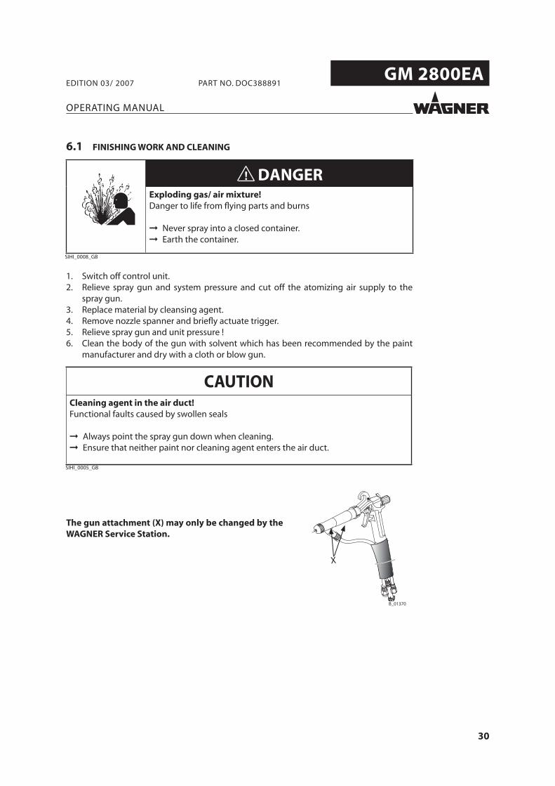
The gun attachment (X) may only be changed by the WAGNER Service Station.
6.1 FINISHING WORK AND CLEANING
1. Switch off control unit.2. Relieve spray gun and system pressure and cut off the atomizing air supply to the
spray gun.3. Replace material by cleansing agent.4. Remove nozzle spanner and briefl y actuate trigger.5. Relieve spray gun and unit pressure !6. Clean the body of the gun with solvent which has been recommended by the paint
manufacturer and dry with a cloth or blow gun.
DANGERExploding gas/ air mixture!Danger to life from flying parts and burns
Never spray into a closed container.Earth the container.
SIHI_0008_GB
CAUTIONCleaning agent in the air duct!Functional faults caused by swollen seals
Always point the spray gun down when cleaning.Ensure that neither paint nor cleaning agent enters the air duct.
SIHI_0005_GB
31
GM 2800EA
OPERATING MANUAL
EDITION 03/ 2007 PART NO. DOC388891
7 TROUBLE SHOOTING AND SOLUTIONS
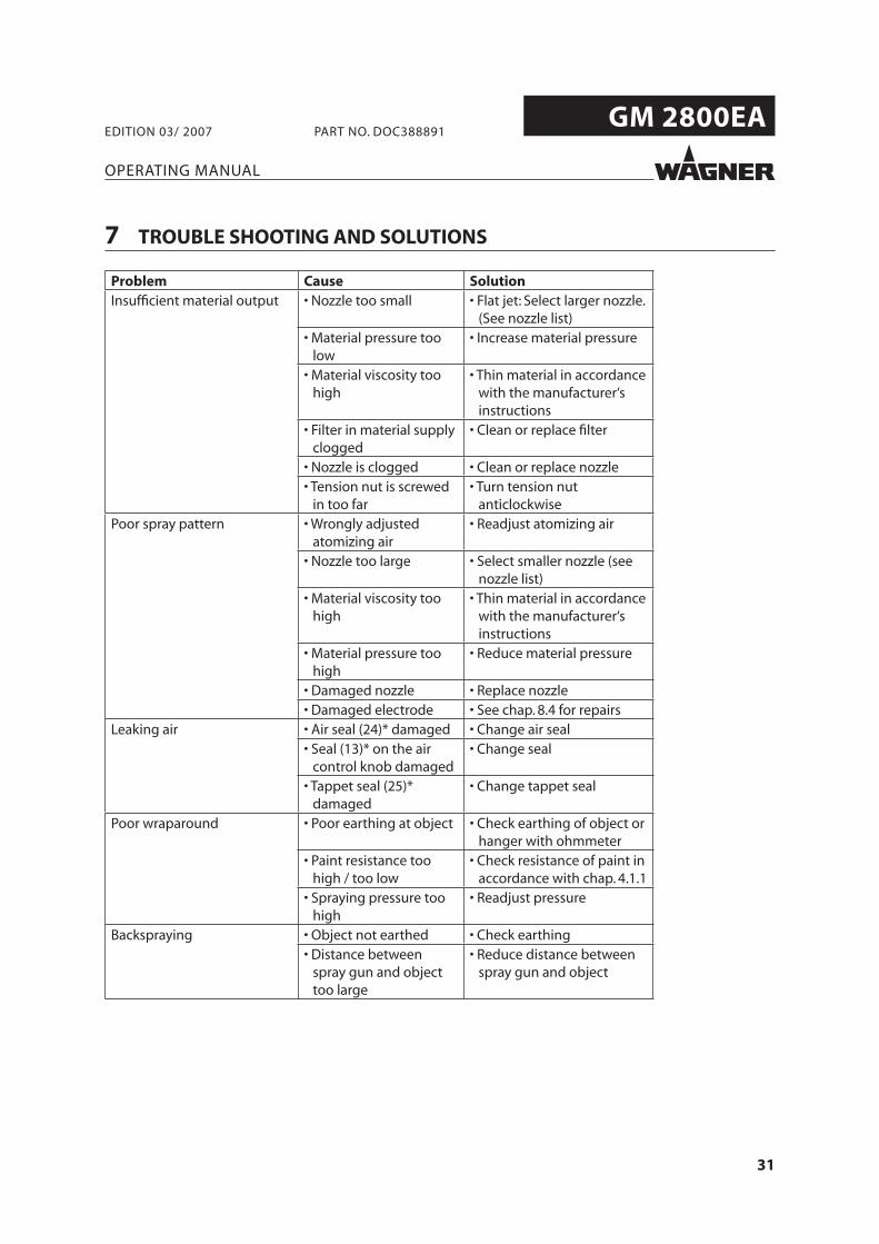
Problem Cause SolutionInsuffi cient material output • Nozzle too small • Flat jet: Select larger nozzle.
(See nozzle list)• Material pressure too
low• Increase material pressure
• Material viscosity too high
• Thin material in accordance with the manufacturer‘s instructions
• Filter in material supply clogged
• Clean or replace fi lter
• Nozzle is clogged • Clean or replace nozzle• Tension nut is screwed
in too far• Turn tension nut
anticlockwisePoor spray pattern • Wrongly adjusted
atomizing air• Readjust atomizing air
• Nozzle too large • Select smaller nozzle (see nozzle list)
• Material viscosity too high
• Thin material in accordance with the manufacturer‘s instructions
• Material pressure too high
• Reduce material pressure
• Damaged nozzle • Replace nozzle• Damaged electrode • See chap. 8.4 for repairs
Leaking air • Air seal (24)* damaged • Change air seal• Seal (13)* on the air
control knob damaged• Change seal
• Tappet seal (25)* damaged
• Change tappet seal
Poor wraparound • Poor earthing at object • Check earthing of object or hanger with ohmmeter
• Paint resistance too high / too low
• Check resistance of paint in accordance with chap. 4.1.1
• Spraying pressure too high
• Readjust pressure
Backspraying • Object not earthed • Check earthing• Distance between
spray gun and object too large
• Reduce distance between spray gun and object
32
GM 2800EA
OPERATING MANUAL
EDITION 03/ 2007 PART NO. DOC388891
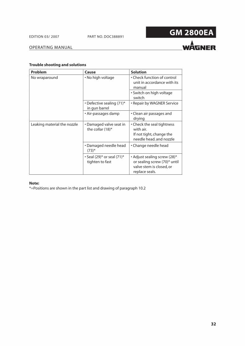
Problem Cause SolutionNo wraparound • No high voltage • Check function of control
unit in accordance with its manual
• Switch on high voltage switch
• Defective sealing (71)* in gun barrel
• Repair by WAGNER Service
• Air-passages damp • Clean air passages and drying
Leaking material the nozzle • Damaged valve seat in the collar (18)*
• Check the seal tightness with air. If not tight, change the needle head. and nozzle
• Damaged needle head (73)*
• Change needle head
• Seal (29)* or seal (71)* tighten to fast
• Adjust sealing screw (28)* or sealing screw (70)* until valve stem is closed, or replace seals.
Note:*=Positions are shown in the part list and drawing of paragraph 10.2
Trouble shooting and solutions
33
GM 2800EA
G
I
B_00174
OPERATING MANUAL
EDITION 03/ 2007 PART NO. DOC388891
8 REPAIR WORK
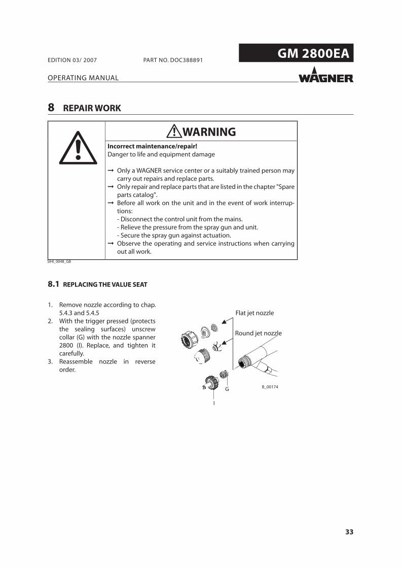
8.1 REPLACING THE VALUE SEAT
1. Remove nozzle according to chap. 5.4.3 and 5.4.5
2. With the trigger pressed (protects the sealing surfaces) unscrew collar (G) with the nozzle spanner 2800 (I). Replace, and tighten it carefully.
3. Reassemble nozzle in reverse order.
Flat jet nozzle
Round jet nozzle
SIHI_0048_GB
WARNINGIncorrect maintenance/repair!Danger to life and equipment damage
Only a WAGNER service center or a suitably trained person maycarry out repairs and replace parts.Only repair and replace parts that are listed in the chapter "Spareparts catalog".Before all work on the unit and in the event of work interrup-tions:- Disconnect the control unit from the mains.- Relieve the pressure from the spray gun and unit. - Secure the spray gun against actuation.Observe the operating and service instructions when carryingout all work.
34
GM 2800EA
OPERATING MANUAL
EDITION 03/ 2007 PART NO. DOC388891
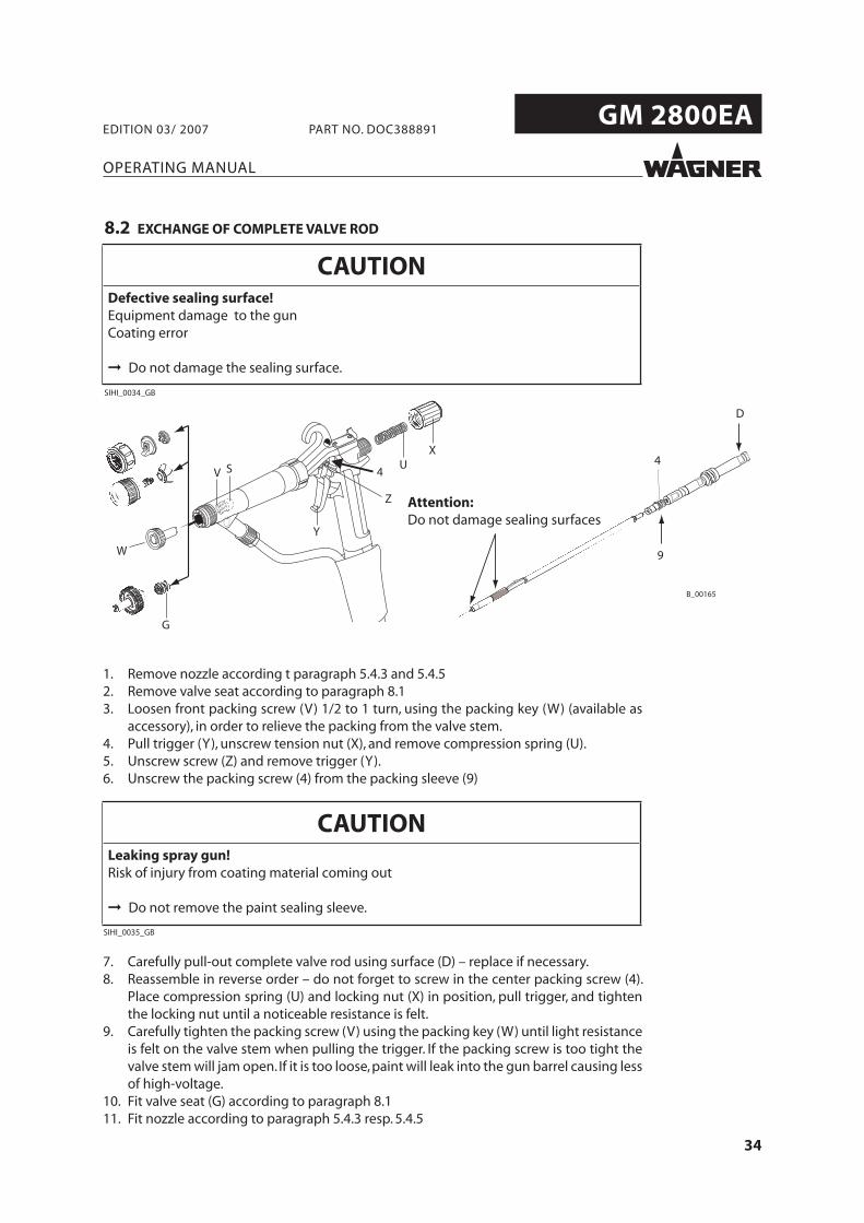
8.2 EXCHANGE OF COMPLETE VALVE ROD
Attention:Do not damage sealing surfaces
1. Remove nozzle according t paragraph 5.4.3 and 5.4.52. Remove valve seat according to paragraph 8.13. Loosen front packing screw (V) 1/2 to 1 turn, using the packing key (W) (available as
accessory), in order to relieve the packing from the valve stem.4. Pull trigger (Y), unscrew tension nut (X), and remove compression spring (U).5. Unscrew screw (Z) and remove trigger (Y).6. Unscrew the packing screw (4) from the packing sleeve (9)
7. Carefully pull-out complete valve rod using surface (D) – replace if necessary.8. Reassemble in reverse order – do not forget to screw in the center packing screw (4).
Place compression spring (U) and locking nut (X) in position, pull trigger, and tighten the locking nut until a noticeable resistance is felt.
9. Carefully tighten the packing screw (V) using the packing key (W) until light resistance is felt on the valve stem when pulling the trigger. If the packing screw is too tight the valve stem will jam open. If it is too loose, paint will leak into the gun barrel causing less of high-voltage.
10. Fit valve seat (G) according to paragraph 8.111. Fit nozzle according to paragraph 5.4.3 resp. 5.4.5
CAUTIONDefective sealing surface!Equipment damage to the gunCoating error
Do not damage the sealing surface.
SIHI_0034_GB
CAUTIONLeaking spray gun! Risk of injury from coating material coming out
Do not remove the paint sealing sleeve.
SIHI_0035_GB
35
GM 2800EA
OPERATING MANUAL
EDITION 03/ 2007 PART NO. DOC388891
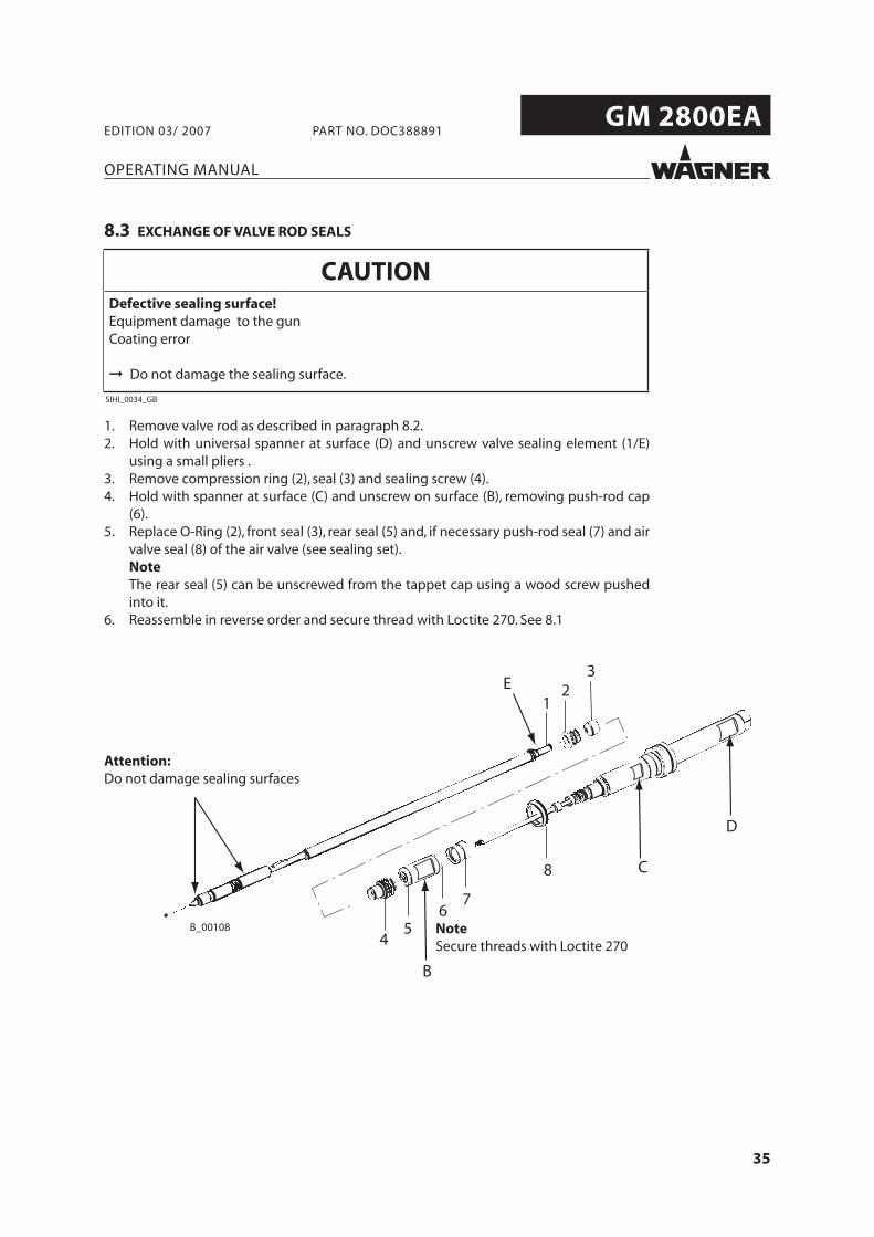
8.3 EXCHANGE OF VALVE ROD SEALS
1. Remove valve rod as described in paragraph 8.2.2. Hold with universal spanner at surface (D) and unscrew valve sealing element (1/E)
using a small pliers .3. Remove compression ring (2), seal (3) and sealing screw (4).4. Hold with spanner at surface (C) and unscrew on surface (B), removing push-rod cap
(6).5. Replace O-Ring (2), front seal (3), rear seal (5) and, if necessary push-rod seal (7) and air
valve seal (8) of the air valve (see sealing set). Note The rear seal (5) can be unscrewed from the tappet cap using a wood screw pushed
into it.6. Reassemble in reverse order and secure thread with Loctite 270. See 8.1
Attention:Do not damage sealing surfaces
NoteSecure threads with Loctite 270
CAUTIONDefective sealing surface!Equipment damage to the gunCoating error
Do not damage the sealing surface.
SIHI_0034_GB
36
GM 2800EA
OPERATING MANUAL
EDITION 03/ 2007 PART NO. DOC388891
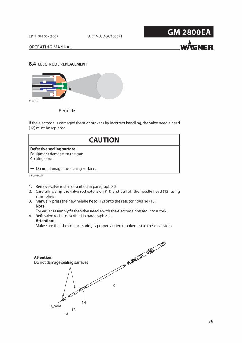
8.4 ELECTRODE REPLACEMENT
Electrode
If the electrode is damaged (bent or broken) by incorrect handling, the valve needle head (12) must be replaced.
1. Remove valve rod as described in paragraph 8.2.2. Carefully clamp the valve rod extension (11) and pull off the needle head (12) using
small pliers.3. Manually press the new needle head (12) onto the resistor housing (13). Note For easier assembly fi t the valve needle with the electrode pressed into a cork.4. Refi t valve rod as described in paragraph 8.2. Attention: Make sure that the contact spring is properly fi tted (hooked-in) to the valve stem.
Attention:Do not damage sealing surfaces
CAUTIONDefective sealing surface!Equipment damage to the gunCoating error
Do not damage the sealing surface.
SIHI_0034_GB
37
GM 2800EA
OPERATING MANUAL
EDITION 03/ 2007 PART NO. DOC388891
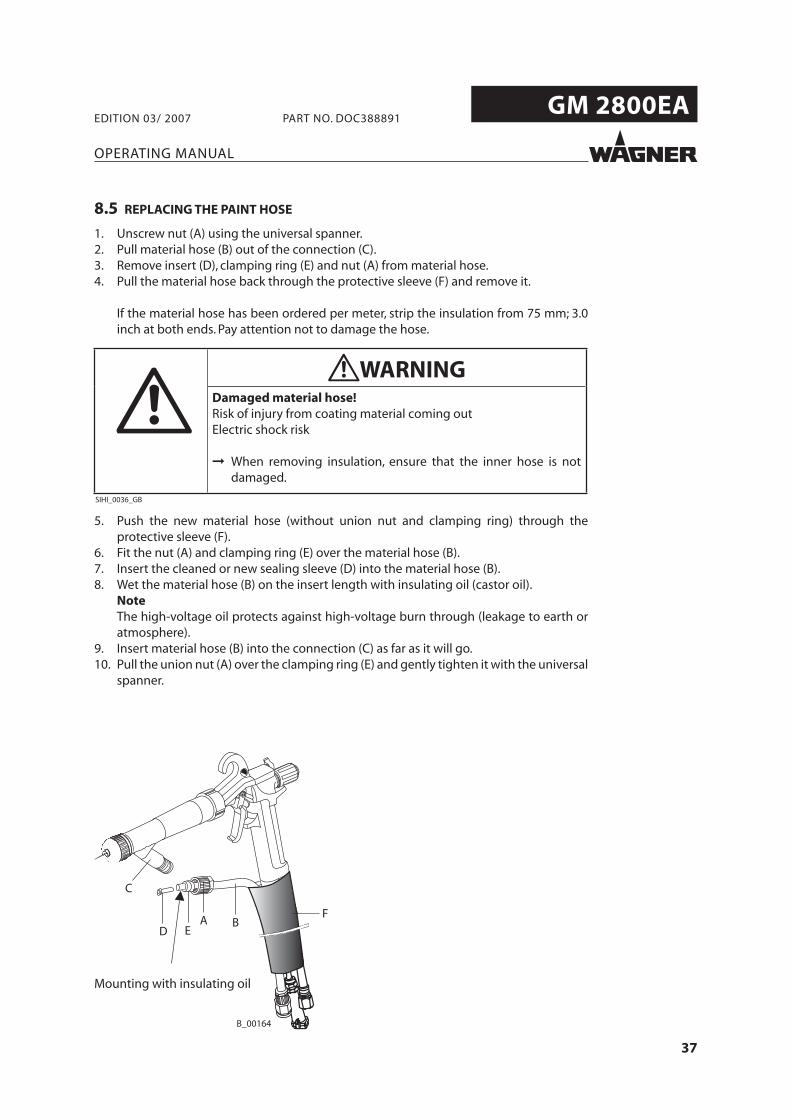
8.5 REPLACING THE PAINT HOSE
1. Unscrew nut (A) using the universal spanner.2. Pull material hose (B) out of the connection (C).3. Remove insert (D), clamping ring (E) and nut (A) from material hose.4. Pull the material hose back through the protective sleeve (F) and remove it.
If the material hose has been ordered per meter, strip the insulation from 75 mm; 3.0 inch at both ends. Pay attention not to damage the hose.
5. Push the new material hose (without union nut and clamping ring) through the protective sleeve (F).
6. Fit the nut (A) and clamping ring (E) over the material hose (B).7. Insert the cleaned or new sealing sleeve (D) into the material hose (B).8. Wet the material hose (B) on the insert length with insulating oil (castor oil). Note The high-voltage oil protects against high-voltage burn through (leakage to earth or
atmosphere).9. Insert material hose (B) into the connection (C) as far as it will go.10. Pull the union nut (A) over the clamping ring (E) and gently tighten it with the universal
spanner.
Mounting with insulating oil
WARNINGDamaged material hose!Risk of injury from coating material coming outElectric shock risk
When removing insulation, ensure that the inner hose is notdamaged.
SIHI_0036_GB
38
GM 2800EA
OPERATING MANUAL
EDITION 03/ 2007 PART NO. DOC388891
9 PRODUCT DISPOSAL
SIHI_0127_GB
NoteDo not dispose of waste electrical equipment with the hou-sehold refuse!In accordance with European Directive 2002/96/EC on the disposalof waste electrical equipment and its implementation in nationallaw, this product may not be disposed of with the household refuse,but must rather be recycled in an environmentally correct manner.Your waste Wagner device will be taken back by us or our represen-tatives and disposed of environmentally correctly. Please contactone of our service points or one of our representatives or us directlyto this purpose.
39
GM 2800EA
0
100
200
300
400
500
600
700
800
1 bar 2 bar 3 bar
ø 0.8ø 1.0ø 1.2ø 1.4ø 1.6ø 1.8ø 2.0
B 00170
OPERATING MANUAL
EDITION 03/ 2007 PART NO. DOC388891
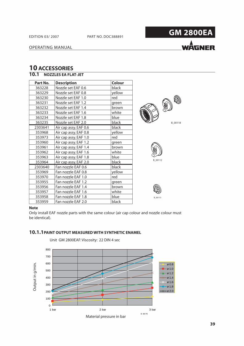
10 ACCESSORIES10.1 NOZZLES EA FLAT-JET
Part No. Description Colour363228 Nozzle set EAF 0.6 black363229 Nozzle set EAF 0.8 yellow363230 Nozzle set EAF 1.0 red363231 Nozzle set EAF 1.2 green363232 Nozzle set EAF 1.4 brown363233 Nozzle set EAF 1.6 white363234 Nozzle set EAF 1.8 blue363235 Nozzle set EAF 2.0 black
2303641 Air cap assy. EAF 0.6 black353968 Air cap assy. EAF 0.8 yellow353973 Air cap assy. EAF 1.0 red353960 Air cap assy. EAF 1.2 green353961 Air cap assy. EAF 1.4 brown353962 Air cap assy. EAF 1.6 white353963 Air cap assy. EAF 1.8 blue353964 Air cap assy. EAF 2.0 black
2303640 Fan nozzle EAF 0.6 black353969 Fan nozzle EAF 0.8 yellow353970 Fan nozzle EAF 1.0 red353955 Fan nozzle EAF 1.2 green353956 Fan nozzle EAF 1.4 brown353957 Fan nozzle EAF 1.6 white353958 Fan nozzle EAF 1.8 blue353959 Fan nozzle EAF 2.0 black
NoteOnly install EAF nozzle parts with the same colour (air cap colour and nozzle colour must be identical).
10.1.1 PAINT OUTPUT MEASURED WITH SYNTHETIC ENAMEL
Unit GM 2800EAF: Viscosity: 22 DIN 4 sec
Material pressure in bar
Ou
tpu
t in
g/m
in.
40
GM 2800EA
OPERATING MANUAL
EDITION 03/ 2007 PART NO. DOC388891
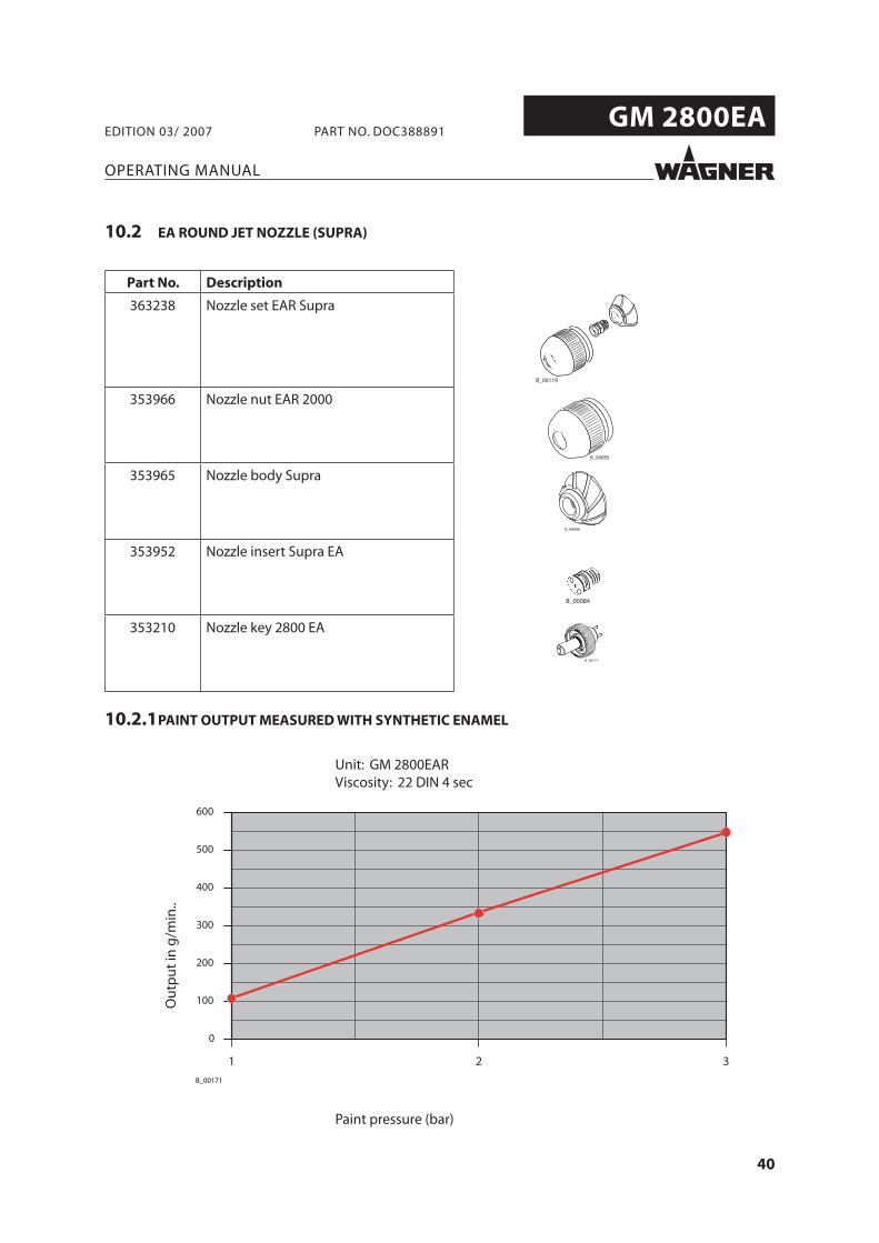
10.2 EA ROUND JET NOZZLE (SUPRA)
Part No. Description
363238 Nozzle set EAR Supra
353966 Nozzle nut EAR 2000
353965 Nozzle body Supra
353952 Nozzle insert Supra EA
353210 Nozzle key 2800 EA
10.2.1 PAINT OUTPUT MEASURED WITH SYNTHETIC ENAMEL
Unit: GM 2800EARViscosity: 22 DIN 4 sec
Paint pressure (bar)
Ou
tpu
t in
g/m
in..
41
GM 2800EA
OPERATING MANUAL
EDITION 03/ 2007 PART NO. DOC388891
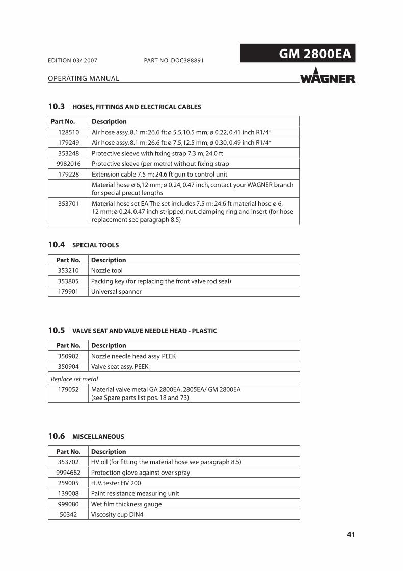
10.3 HOSES, FITTINGS AND ELECTRICAL CABLES
Part No. Description
128510 Air hose assy. 8.1 m; 26.6 ft; ø 5.5,10.5 mm; ø 0.22, 0.41 inch R1/4“
179249 Air hose assy. 8.1 m; 26.6 ft: ø 7.5,12.5 mm; ø 0.30, 0.49 inch R1/4“
353248 Protective sleeve with fi xing strap 7.3 m; 24.0 ft
9982016 Protective sleeve (per metre) without fi xing strap
179228 Extension cable 7.5 m; 24.6 ft gun to control unit
Material hose ø 6,12 mm; ø 0.24, 0.47 inch, contact your WAGNER branch for special precut lengths
353701 Material hose set EA The set includes 7.5 m; 24.6 ft material hose ø 6, 12 mm; ø 0.24, 0.47 inch stripped, nut, clamping ring and insert (for hose replacement see paragraph 8.5)
10.6 MISCELLANEOUS
Part No. Description
353702 HV oil (for fi tting the material hose see paragraph 8.5)
9994682 Protection glove against over spray
259005 H. V. tester HV 200
139008 Paint resistance measuring unit
999080 Wet fi lm thickness gauge
50342 Viscosity cup DIN4
10.4 SPECIAL TOOLS
Part No. Description
353210 Nozzle tool
353805 Packing key (for replacing the front valve rod seal)
179901 Universal spanner
10.5 VALVE SEAT AND VALVE NEEDLE HEAD - PLASTIC
Part No. Description
350902 Nozzle needle head assy. PEEK
350904 Valve seat assy. PEEK
Replace set metal
179052 Material valve metal GA 2800EA, 2805EA/ GM 2800EA (see Spare parts list pos. 18 and 73)
42
GM 2800EA
OPERATING MANUAL
EDITION 03/ 2007 PART NO. DOC388891
11 SPARE PARTS CATALOGUE
11.1 HOW TO ORDER SPARE PARTS?
SIHI_0004_GB
WARNINGIncorrect maintenance/repair!Risk of injury and damage to the equipment
Repairs and part replacement may only be carried out by spe-cially trained staff or a WAGNER service center.Before all work on the unit and in the event of work interrup-tions:- Switch off the energy/compressed air supply.- Relieve the pressure from the spray gun and unit. - Secure the spray gun against actuation.Observe the operating and service instructions when carryingout all work.
43
GM 2800EA
13 12
36
40 14 15 54 55
39
41
38
104103
102
101
111
112113
110
61
58 57
6366
34
21
28
26
25
24
23
20
22
1933
73
4
100293031
32
7018
65
71
72
64
62
114
17
GM 2800EA
B_00083
27115
116
OPERATING MANUAL
EDITION 03/ 2007 PART NO. DOC388891
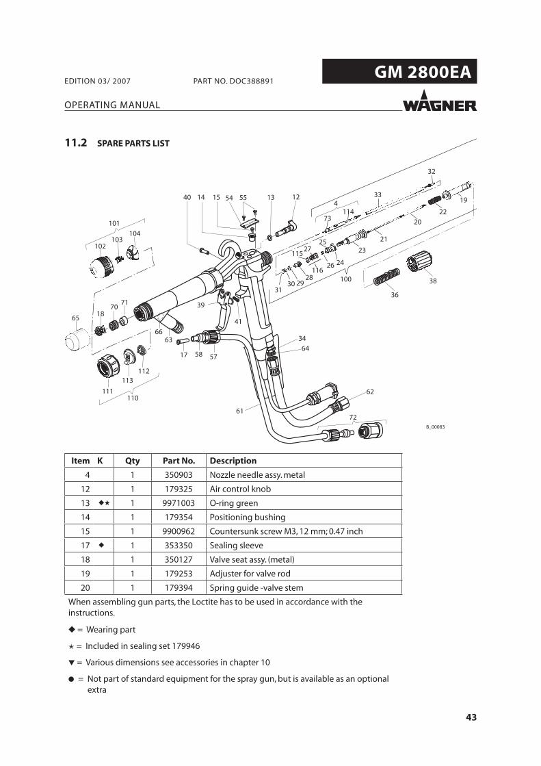
Item K Qty Part No. Description
4 1 350903 Nozzle needle assy. metal
12 1 179325 Air control knob
13 ◆★ 1 9971003 O-ring green
14 1 179354 Positioning bushing
15 1 9900962 Countersunk screw M3, 12 mm; 0.47 inch
17 ◆ 1 353350 Sealing sleeve
18 1 350127 Valve seat assy. (metal)
19 1 179253 Adjuster for valve rod
20 1 179394 Spring guide -valve stem
When assembling gun parts, the Loctite has to be used in accordance with the instructions.
◆ = Wearing part
✭ = Included in sealing set 179946
▼ = Various dimensions see accessories in chapter 10
● = Not part of standard equipment for the spray gun, but is available as an optional extra
11.2 SPARE PARTS LIST
44
GM 2800EA
OPERATING MANUAL
EDITION 03/ 2007 PART NO. DOC388891
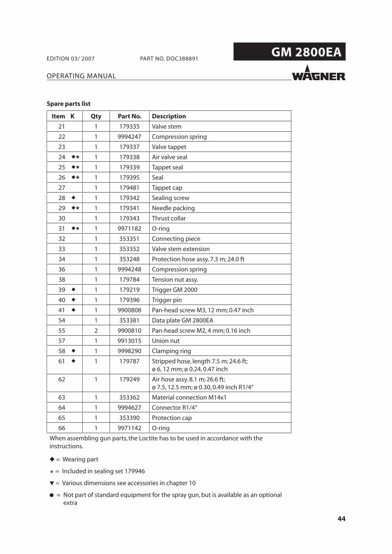
Item K Qty Part No. Description
21 1 179335 Valve stem
22 1 9994247 Compression spring
23 1 179337 Valve tappet
24 ◆★ 1 179338 Air valve seal
25 ◆★ 1 179339 Tappet seal
26 ◆★ 1 179395 Seal
27 1 179481 Tappet cap
28 ◆ 1 179342 Sealing screw
29 ◆★ 1 179341 Needle packing
30 1 179343 Thrust collar
31 ◆★ 1 9971182 O-ring
32 1 353351 Connecting piece
33 1 353352 Valve stem extension
34 1 353248 Protection hose assy. 7.3 m; 24.0 ft
36 1 9994248 Compression spring
38 1 179784 Tension nut assy.
39 ◆ 1 179219 Trigger GM 2000
40 ◆ 1 179396 Trigger pin
41 ◆ 1 9900808 Pan-head screw M3, 12 mm; 0.47 inch
54 1 353381 Data plate GM 2800EA
55 2 9900810 Pan-head screw M2, 4 mm; 0.16 inch
57 1 9913015 Union nut
58 ◆ 1 9998290 Clamping ring
61 ◆ 1 179787 Stripped hose, length 7.5 m; 24.6 ft; ø 6, 12 mm; ø 0.24, 0.47 inch
62 1 179249 Air hose assy. 8.1 m; 26.6 ft; ø 7.5, 12.5 mm; ø 0.30, 0.49 inch R1/4“
63 1 353362 Material connection M14x1
64 1 9994627 Connector R1/4“
65 1 353390 Protection cap
66 1 9971142 O-ring
When assembling gun parts, the Loctite has to be used in accordance with the instructions.
◆ = Wearing part
✭ = Included in sealing set 179946
▼ = Various dimensions see accessories in chapter 10
● = Not part of standard equipment for the spray gun, but is available as an optional extra
Spare parts list
45
GM 2800EA
OPERATING MANUAL
EDITION 03/ 2007 PART NO. DOC388891
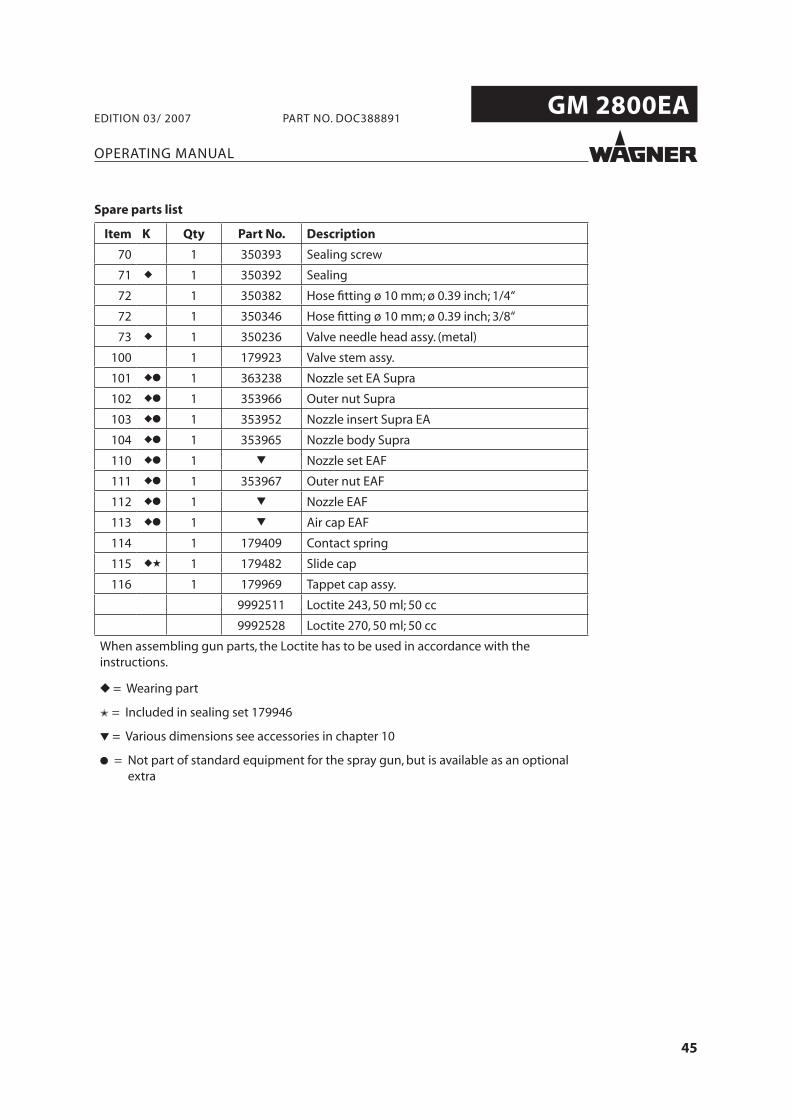
Item K Qty Part No. Description
70 1 350393 Sealing screw
71 ◆ 1 350392 Sealing
72 1 350382 Hose fi tting ø 10 mm; ø 0.39 inch; 1/4“
72 1 350346 Hose fi tting ø 10 mm; ø 0.39 inch; 3/8“
73 ◆ 1 350236 Valve needle head assy. (metal)
100 1 179923 Valve stem assy.
101 ◆● 1 363238 Nozzle set EA Supra
102 ◆● 1 353966 Outer nut Supra
103 ◆● 1 353952 Nozzle insert Supra EA
104 ◆● 1 353965 Nozzle body Supra
110 ◆● 1 ▼ Nozzle set EAF
111 ◆● 1 353967 Outer nut EAF
112 ◆● 1 ▼ Nozzle EAF
113 ◆● 1 ▼ Air cap EAF
114 1 179409 Contact spring
115 ◆★ 1 179482 Slide cap
116 1 179969 Tappet cap assy.
9992511 Loctite 243, 50 ml; 50 cc
9992528 Loctite 270, 50 ml; 50 cc
When assembling gun parts, the Loctite has to be used in accordance with the instructions.
◆ = Wearing part
✭ = Included in sealing set 179946
▼ = Various dimensions see accessories in chapter 10
● = Not part of standard equipment for the spray gun, but is available as an optional extra
Spare parts list
46
GM 2800EA
OPERATING MANUAL
EDITION 03/ 2007 PART NO. DOC388891
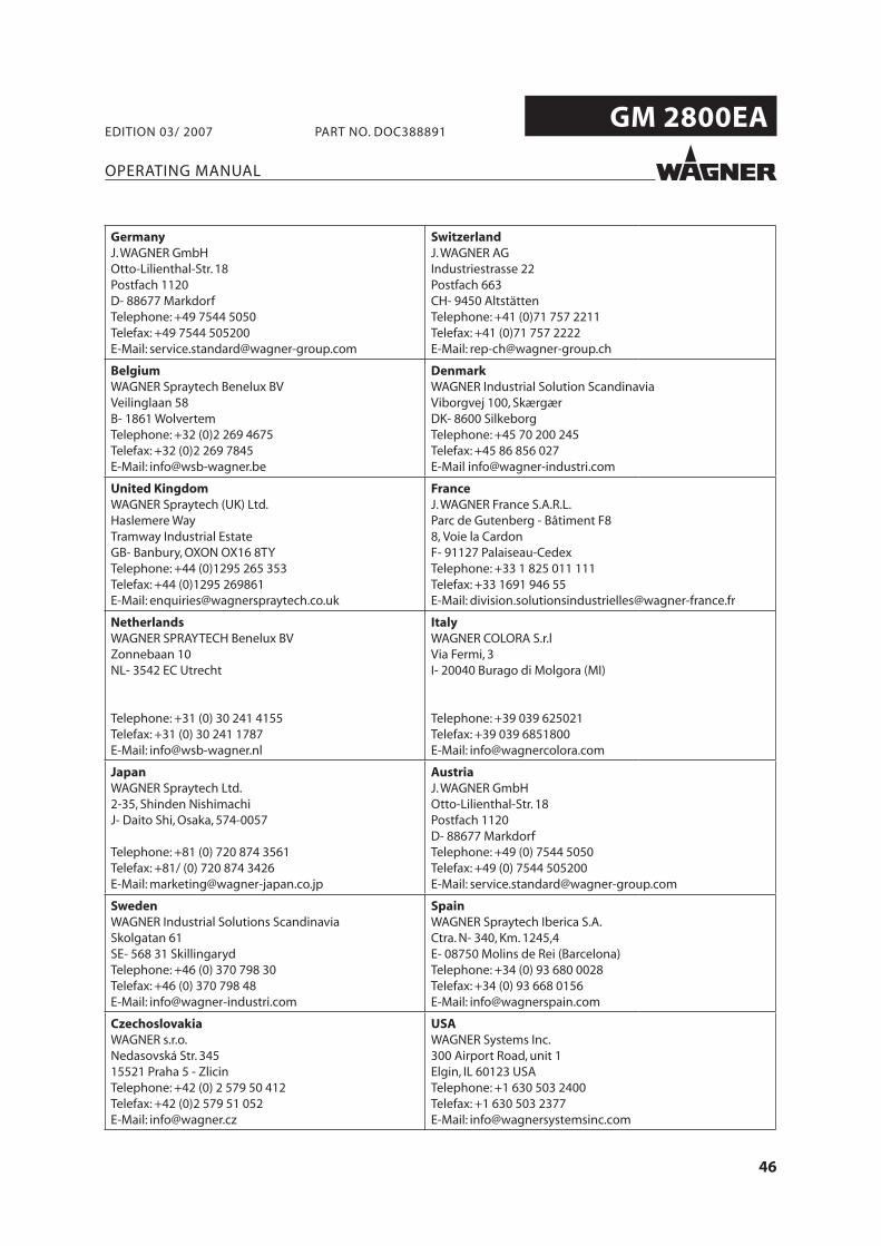
GermanyJ.WAGNER GmbHOtto-Lilienthal-Str. 18Postfach 1120D- 88677 MarkdorfTelephone: +49 7544 5050Telefax: +49 7544 505200E-Mail: [email protected]
SwitzerlandJ.WAGNER AGIndustriestrasse 22Postfach 663CH- 9450 AltstättenTelephone: +41 (0)71 757 2211Telefax: +41 (0)71 757 2222E-Mail: [email protected]
BelgiumWAGNER Spraytech Benelux BVVeilinglaan 58B- 1861 WolvertemTelephone: +32 (0)2 269 4675Telefax: +32 (0)2 269 7845E-Mail: [email protected]
DenmarkWAGNER Industrial Solution ScandinaviaViborgvej 100, SkærgærDK- 8600 SilkeborgTelephone: +45 70 200 245Telefax: +45 86 856 027E-Mail [email protected]
United KingdomWAGNER Spraytech (UK) Ltd.Haslemere WayTramway Industrial EstateGB- Banbury, OXON OX16 8TYTelephone: +44 (0)1295 265 353Telefax: +44 (0)1295 269861E-Mail: [email protected]
FranceJ.WAGNER France S.A.R.L.Parc de Gutenberg - Bâtiment F88, Voie la CardonF- 91127 Palaiseau-CedexTelephone: +33 1 825 011 111Telefax: +33 1691 946 55E-Mail: [email protected]
NetherlandsWAGNER SPRAYTECH Benelux BVZonnebaan 10NL- 3542 EC Utrecht
Telephone: +31 (0) 30 241 4155Telefax: +31 (0) 30 241 1787E-Mail: [email protected]
ItalyWAGNER COLORA S.r.lVia Fermi, 3I- 20040 Burago di Molgora (MI)
Telephone: +39 039 625021Telefax: +39 039 6851800E-Mail: [email protected]
JapanWAGNER Spraytech Ltd.2-35, Shinden NishimachiJ- Daito Shi, Osaka, 574-0057
Telephone: +81 (0) 720 874 3561Telefax: +81/ (0) 720 874 3426E-Mail: [email protected]
AustriaJ.WAGNER GmbHOtto-Lilienthal-Str. 18Postfach 1120D- 88677 MarkdorfTelephone: +49 (0) 7544 5050Telefax: +49 (0) 7544 505200E-Mail: [email protected]
SwedenWAGNER Industrial Solutions ScandinaviaSkolgatan 61SE- 568 31 SkillingarydTelephone: +46 (0) 370 798 30Telefax: +46 (0) 370 798 48E-Mail: [email protected]
SpainWAGNER Spraytech Iberica S.A.Ctra. N- 340, Km. 1245,4E- 08750 Molins de Rei (Barcelona)Telephone: +34 (0) 93 680 0028Telefax: +34 (0) 93 668 0156E-Mail: [email protected]
CzechoslovakiaWAGNER s.r.o.Nedasovská Str. 34515521 Praha 5 - ZlicinTelephone: +42 (0) 2 579 50 412Telefax: +42 (0)2 579 51 052E-Mail: [email protected]
USAWAGNER Systems Inc.300 Airport Road, unit 1Elgin, IL 60123 USATelephone: +1 630 503 2400Telefax: +1 630 503 2377E-Mail: [email protected]

CERTIFIE
D
388891