Embed Size (px)
Citation preview
http://www.bio-protocol.org/e1498 Vol 5, Iss 12, Jun 20, 2015
Copyright © 2015 The Authors; exclusive licensee Bio-protocol LLC. 1
Electroporation of Embryonic Chick Eyes Agustín Luz-Madrigal1, 2, Erika Grajales-Esquivel1 and Katia Del Rio-Tsonis1*
1Department of Biology, Miami University and Center for Visual Sciences at Miami University
(CVSMU), Oxford, USA; 2Department of Biology, University of Dayton and Center for Tissue
Regeneration and Engineering at the University of Dayton (TREND), Dayton, USA *For correspondence: [email protected]
[Abstract] The chick embryo has prevailed as one of the major models to study
developmental biology, cell biology and regeneration. From all the anatomical features of the
chick embryo, the eye is one of the most studied. In the chick embryo, the eye develops
between 26 and 33 h after incubation (Stages 8-9, Hamburger and Hamilton, 1951). It
originates from the posterior region of the forebrain, called the diencephalon. However, the
vertebrate eye includes tissues from different origins including surface ectoderm (lens and
cornea), anterior neural plate (retina, iris, ciliary body and retinal pigmented epithelium) and
neural crest/head mesoderm (stroma of the iris and of the ciliary body as well as choroid,
sclera and part of the cornea). After gastrulation, a single eye field originates from the anterior
neural plate and is characterized by the expression of eye field transcriptional factors (EFTFs)
that orchestrate the program for eye development. Later in development, the eye field
separates in two and the optic vesicles form. After several inductive interactions with the lens
placode, the optic cup forms. At Stages 14-15, the outer layer of the optic cup becomes the
retinal pigmented epithelium (RPE) while the inner layer forms the neuroepithelium that
eventually differentiates into the retina. One main advantage of the chick embryo, is the
possibility to perform experiments to over-express or to down-regulate gene expression in a
place and time specific manner to explore gene function and regulation. The aim of this
protocol is to describe the electroporation techniques at Stages 8-12 (anterior neural fold and
optic vesicle stages) and Stages 19-26 (eye cup, RPE and neuroepithelium). We provide a full
description of the equipment, materials and electrode set up as well as a detailed description
of the highly reproducible protocol including some representative results. This protocol has
been adapted from our previous publications Luz-Madrigal et al. (2014) and Zhu et al. (2014).
Materials and Reagents 1. Fertilized specific pathogen free (SPF) (Charles River Laboratories) or white Leghorn
chicken eggs (Note 1)
2. 10x Hank's balanced salt solution (HBSS) (Thermo Fisher Scientific, catalog number:
14185-052)
3. Fast green FCF (Sigma-Aldrich, catalog number: F7258)
4. Indian Ink Type A (Pelikan)

http://www.bio-protocol.org/e1498 Vol 5, Iss 12, Jun 20, 2015
Copyright © 2015 The Authors; exclusive licensee Bio-protocol LLC. 2
5. Tris (hydroxymethyl) aminomethane (suitable for cell culture) (Sigma-Aldrich, catalog
number: 252859)
6. EDTA (Ethylenediaminetetraacetic acid), suitable for cell culture (Sigma-Aldrich, catalog
number: E6758)
7. pCAG- GFP (Addgene plasmid, catalog number: 11150) or pEGFP-N1 (Takara Bio
Company, Clontech)
8. Plasmid and RCAS-DNA [the name RCAS stands for Replication-Competent ASLV long
terminal repeat (LTR) with a Splice acceptor] (Note 6)
9. Morpholinos (Note 7)
10. NaCl (Fisher Scientific, catalog number: BP358-1) (MW 58.44 g/mol)
11. CaCl2 anhydrous (Acros Organics, catalog number: AC34961-5000) (MW 110.98 g/mol)
12. KCl (Fisher Scientific, catalog number: P217-500) (MW 74.55 g/mol)
13. Na2HPO4 Dibasic anhydrous (Fisher Scientific, catalog number: S374-500) (MW 141.96
g/mol)
14. KH2PO4 Dibasic Anhydrous (Fisher Scientific, catalog number: P290-500) (MW 174.18
g/mol)
15. Ringer’s solution (see Recipes)
16. 10x Hank's balanced salt solution (HBSS) (see Recipes)
17. Fast green FCF (see Recipes)
18. 1 M Tris (see Recipes)
19. 0.5 M EDTA (see Recipes)
20. TE buffer for plasmid solutions (see Recipes)
Equipment
1. Beveled-edge watch glass (to hold the egg during the electroporation) (Thermo Fisher
Scientific, catalog number: 15-355)
2. 200 μl tips sterile (Corning Incorporated)
3. Capillary tubing borosilicate for microinjection (1.0 mm OD, 0.5 mm ID/fiber) [Frederick
Haer & Co (FHC), catalog number: 30-30-1]
4. 1 ml syringe (Thermo Fisher Scientific)
5. Pre-pulled beveled glass needles 50 mm long, 20 µm tip diameter and sharpened 10
to 12° (these glass needles are made following the instructions of the Micropipette
Puller and Micropipette Beveler- Figure 1d-e)
6. 35 mm plastic tissue culture plates (Corning Incorporated)
7. 3/4 inch wide clear tape (Scotch, 3 M)
8. Micro dissecting tweezers #55 and #5 (Roboz, catalog numbers: RS-4984 and
RS-4978)
9. ECM 830 High Throughput Electroporation System (Figure 1a), a Square Wave Pulse
generator for in vitro and in vivo electroporation with remote operation Footswitch
http://www.bio-protocol.org/e1498 Vol 5, Iss 12, Jun 20, 2015
Copyright © 2015 The Authors; exclusive licensee Bio-protocol LLC. 3
(BTX, Harvard Apparatus, SKU: ECM_830_for_In_Vivo_Applications)
10. Microinjector (Figure 1b), MicroJect 1000A (BTX, Harvard Apparatus, SKU: 45- 0750)
with foot Switches to inject and fill and a stainless steel pipette holder (Figure 1c)
11. Micropipette beveler (Sutter Instrument Company, model: BV-10) (Figure 1d)
12. Vertical micropipette puller (Sutter Instrument Company, model: P-30) (Figure 1e)
13. Nitrogen tank Compressed 2.2 UN1066 NI NI230PP 230CF PP (CAGA580) (Weiler
Welding)
14. Stereo zoom microscope (Motic, model: SMZ-168, catalog number: 1100200500322)
or equivalent
15. Tungsten halogen light source (series equipped with Fiber Optic, model: 8375)
(Fostec ACE)
16. Rotating incubator (45 of angle rotation every hour) calibrated at 37-39 °C (99 to
103 °F) and relative humidity of 50-55% (83-87 °F or 28-31 °C, on wet bulb
thermometer) (e.g. Breeding Technology, 1202E Classic Sportsman,
https://www.gqfmfg.com/store/front.asp)
17. Incubator Thermal Air Hova-Bator (https://www.gqfmfg.com/store/front.asp)
18. 200 μl micropipette
19. Blue-light filter (12.5 mm diameter, ~100% transmittance up to 500 nm) (Edmond
Optics, catalog number: 52-530)
20. Electrodes (Note 8)
a. Stage-8-12 electrodes (for set up see Figure 2)
i. Platinum/Iridium (Pt/Ir) Microelectrodes unit of 3 (Frederick Haer&Co, catalog
number: UEPMEEVENNND), use the following Metal Microelectrode Spec
Sheet (http://www.fh-co.com/uploads/files/ue-spec-2013.pdf) for ordering
ii. Extreme-Temperature Polyimide Tubing (0.007" ID, 1/16", OD, 0.08" Wall,
1'L,Clear Amber, McMasterCarr, catalog number: 5707K12)
iii. Plastic holder (made utilizing a 20 µl pipet tip) with ~2 mm diameter and ~3
mm length (see Figure 2 c1-2)
iv. Bend-and-Stay 302/304 Stainless Steel Wire (0.032" diameter, 1' Long,
McMASTER- CARR, catalog number: 6517K66)
v. Precision Miniature Stainless Steel Tubing, 304 Stainless Steel, 15 Gauge,
0.072" OD, 0.05" ID, .011" Wall (McMASTER-CARR, catalog number:
8988K31)
vi. White Delrin® Acetal Resin Rod, 3/8" Diameter (McMASTER-CARR, catalog
number: 8572K53). This Resin Rod is modified with a press fit to incorporate
internally the Stainless Steel Tubing (material #v) and to fit in the
polycarbonate tube that functions as a hand holder (material #vii) (Figure 1d).
vii. Impact-Resistant Polycarbonate Round Tube (McMASTER-CARR, catalog
number: 8585K11)
viii. 1 m of 26 gauge (stranded, aluminum wire)

http://www.bio-protocol.org/e1498 Vol 5, Iss 12, Jun 20, 2015
Copyright © 2015 The Authors; exclusive licensee Bio-protocol LLC. 4
ix. Connector; BNC; Nickel Plated Brass; 20; Gold Plated Beryllium Copper; PVC
(Pomona, catalog number: 4969)
x. Flow Mix 60 sec (Epoxy, 1250 psi Strength, part number: 21445) (Devcon)
b. Stage-19-26 electrodes (for set up see Figure 3)
i. One genetrode kit (5 mm, Gold plated thick electrode - L-shaped, in ovo gene)
(Harvard Apparatus, model: 512, catalog number: 45-0115)
ii. One platinum/iridium microelectrode unit of 3 (Frederick Haer & Co, catalog
number: UEPMEEVENNND), see part “i” from Stage-8-12 electrodes for
ordering instructions.
iii. Tygon® microbore tubing ( 0.010" ID x 0.030"OD, 100 ft/roll) (Cole-Parmer,
catalog number: EW-06419-00) (Characteristics: Extremely flexible, non-toxic;
nonpyrogenic; biocompatible) (Formulation Tygon, catalog number:
ND-100-80)
iv. Extreme-Temperature Polyimide Tubing .0089" ID, .0104", OD, .0008" Wall (1
L, Clear Amber) (McMaster-Carr, catalog number: 51085K42)
v. One Capillary tubing borosilicate for Microinjection, 1.0 mm OD, 0.5 mm
ID/fiber (Frederick Haer&Co, catalog number: 30-30-1)
vi. One 1 ml pipet tip (Corning Incorporated)
vii. 50 cm aluminum wire (stranded), 26 gauge
viii. Connector; BNC; Nickel Plated Brass; 20; Gold Plated Beryllium Copper; PVC
(Pomona, catalog number: 4969)
ix. Flow mix 60 sec (Epoxy, 1250 psi Strength, part number: 21445) (Devcon)
Figure 1. Electroporation equipment. The electroporation equipment consist of the
ECM 830 electroporator (a), Microinjector MicroJect 1000A and stainless steel pipette
holder (b, c), Micropipette Beveler and Puller necessary to make glass needles (d, e).
http://www.bio-protocol.org/e1498 Vol 5, Iss 12, Jun 20, 2015
Copyright © 2015 The Authors; exclusive licensee Bio-protocol LLC. 5
Procedure A. Chicken egg manipulation and incubation
1. Prior to incubation, fertilized specific pathogen free (SPF) (Charles River Laboratories,
Wilmington) (Note 1) or White Leghorn chicken eggs (Michigan State University, East
Lansing, MI) are stored at room temperature up to 5 days without significant decrease
in viability (80-85% viability) or defects in development (Note 2).
2. Before incubating the eggs, check the conditions of the incubator (Note 3).
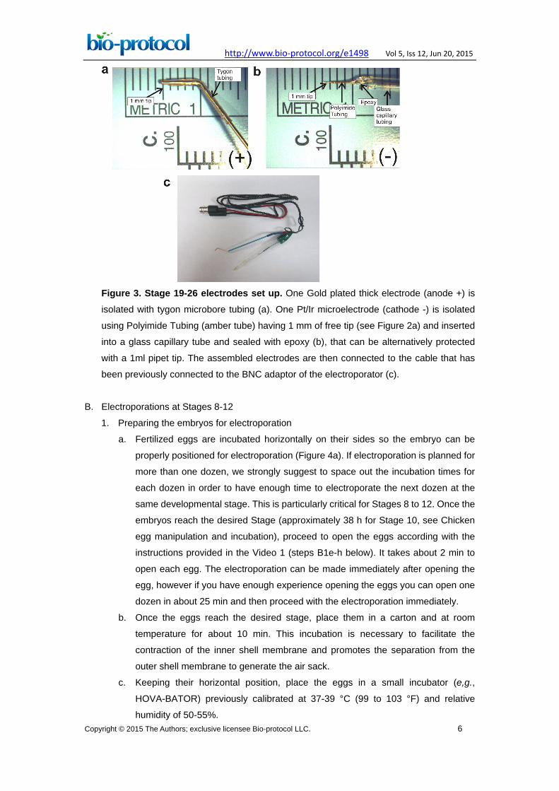
3. For electroporations in the eye, we incubate the eggs approximately 35 h for Stages
8-9 (seven somites, the anterior neural folds closes to form the neural tube), 38 h for
Stage 10 (ten somites, optic vesicles not constricted at bases), 48 h for Stage 12
(sixteen somites, optic vesicle and optic stalk established), 72 h for Stage 14 (optic
vesicle evaginated and lens-placode present) or 4.5 days for Stage 22 [eye pigmented,
retinal pigmented epithelium (RPE) and neuroepithelium well established] (Note 4).
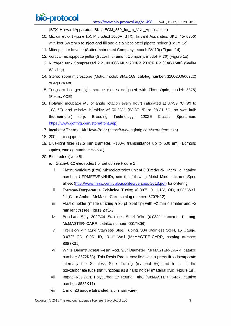
Figure 2. Stage 8-12 electrodes set up. Two isolated Pt/Ir electrodes with Polyimide
Tubing (amber tube) having 1 mm of free tip (a) are bent as is indicated (b). Thereafter, the
bent electrodes are inserted into a small plastic holder (made from a 20 µl pipet tip) with ~2
mm diameter (c1) and ~3 mm length (c2) keeping at the tip 1.5 mm in between (c). The
electrodes are inserted into the holder made of Stainless Steel Tube (SST) and Resin Rod
(RR) that has been modified with a press fit (d). Carefully, electrodes are permanently
attached to the holder using epoxy. It is critical to keep the shape and 1.5 mm distance
between the electrodes during this procedure (e). Finally, the Pt/Ir electrodes are
connected to the cable that has been previously connected to the BNC adaptor of the
electroporator.
http://www.bio-protocol.org/e1498 Vol 5, Iss 12, Jun 20, 2015
Copyright © 2015 The Authors; exclusive licensee Bio-protocol LLC. 6
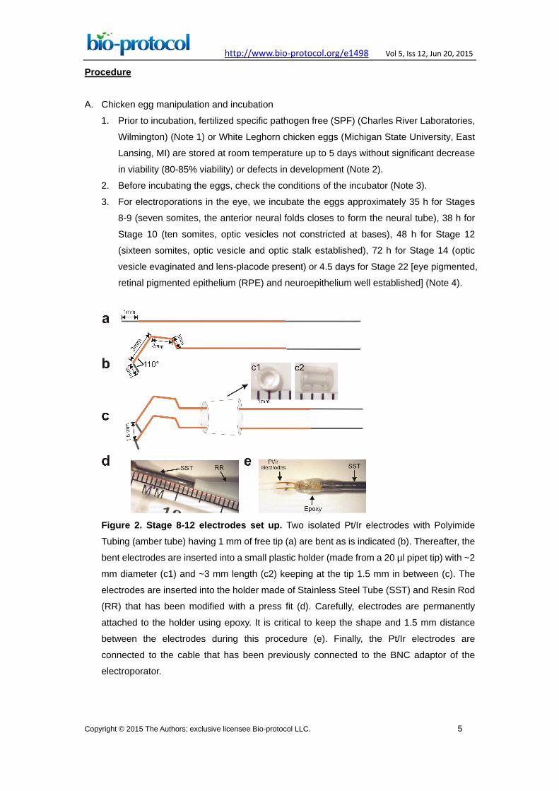
Figure 3. Stage 19-26 electrodes set up. One Gold plated thick electrode (anode +) is
isolated with tygon microbore tubing (a). One Pt/Ir microelectrode (cathode -) is isolated
using Polyimide Tubing (amber tube) having 1 mm of free tip (see Figure 2a) and inserted
into a glass capillary tube and sealed with epoxy (b), that can be alternatively protected
with a 1ml pipet tip. The assembled electrodes are then connected to the cable that has
been previously connected to the BNC adaptor of the electroporator (c).
B. Electroporations at Stages 8-12
1. Preparing the embryos for electroporation
a. Fertilized eggs are incubated horizontally on their sides so the embryo can be
properly positioned for electroporation (Figure 4a). If electroporation is planned for
more than one dozen, we strongly suggest to space out the incubation times for
each dozen in order to have enough time to electroporate the next dozen at the
same developmental stage. This is particularly critical for Stages 8 to 12. Once the
embryos reach the desired Stage (approximately 38 h for Stage 10, see Chicken
egg manipulation and incubation), proceed to open the eggs according with the
instructions provided in the Video 1 (steps B1e-h below). It takes about 2 min to
open each egg. The electroporation can be made immediately after opening the
egg, however if you have enough experience opening the eggs you can open one
dozen in about 25 min and then proceed with the electroporation immediately.
b. Once the eggs reach the desired stage, place them in a carton and at room
temperature for about 10 min. This incubation is necessary to facilitate the
contraction of the inner shell membrane and promotes the separation from the
outer shell membrane to generate the air sack.
c. Keeping their horizontal position, place the eggs in a small incubator (e,g.,
HOVA-BATOR) previously calibrated at 37-39 °C (99 to 103 °F) and relative
humidity of 50-55%.
http://www.bio-protocol.org/e1498 Vol 5, Iss 12, Jun 20, 2015
Copyright © 2015 The Authors; exclusive licensee Bio-protocol LLC. 7
d. With a bright light source, candle the egg and mark the area where the embryo is
located, usually the embryo is located in the top part of the yolk (on the top of the
horizontal section of the shell).
e. Mark the air sack that is located between the outer and inner membranes of the
egg.
f. Pierce the shell at the top of the air sack using blunt ended forceps or a syringe
with a large bore needle.
g. Carefully, introduce a fine probe to move the air sack to the top part of the egg,
this is possible by gently touching down to lower the inner shell membrane (Figure
4b-c) (Note 5).
h. Using sharp curved scissors or blunt ended forceps, open a round window on the
top of the embryo (around 2 cm of diameter) (Figure 4d) (Video 1 provides visual
information of the steps B1e-h) and add 200 μl of HBSS. Close the window using
transparent tape and return the egg to the incubator. Discard the embryos older
than the desired stage. If the embryos have not reached the desired stage, they
can be incubated for an additional time.
Variations on the embryonic stage in which the electroporation is performed will
produce inconsistency on the results and interpretation.
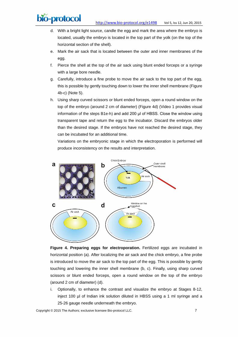
Figure 4. Preparing eggs for electroporation. Fertilized eggs are incubated in
horizontal position (a). After localizing the air sack and the chick embryo, a fine probe
is introduced to move the air sack to the top part of the egg. This is possible by gently
touching and lowering the inner shell membrane (b, c). Finally, using sharp curved
scissors or blunt ended forceps, open a round window on the top of the embryo
(around 2 cm of diameter) (d).
i. Optionally, to enhance the contrast and visualize the embryo at Stages 8-12,
inject 100 µl of Indian ink solution diluted in HBSS using a 1 ml syringe and a
25-26 gauge needle underneath the embryo.
http://www.bio-protocol.org/e1498 Vol 5, Iss 12, Jun 20, 2015
Copyright © 2015 The Authors; exclusive licensee Bio-protocol LLC. 8
j. Repeat steps B1e-h for the rest of the eggs until the dozen is completed.
Video 1. Preparing the eggs for electroporation
2. Embryo electroporation
a. Adjust the nitrogen tank to 80 psi.
b. Attach the beveled glass capillary needle to the stainless steel pipette holder of
the microinjector (Figure 1c).
c. Set the microinjector at 18-20 psi and perform a test loading HBSS using the “fill”
button or the footswitch and release the solution pushing the button “empty” from
the microinjector. Test the microinjection system using the Footswitch.
d. Attach the blue dichroic filter to the optical path of the Tungsten Halogen Light
Source. Configure the electroporator with the following settings: Mode, LV; voltage,
18 V; pulse length, 50 ms; number of pulses, 5; pulse interval, 950 ms; polarity,
unipolar.
e. Connect the Stage-8-12 electrodes (see the equipment section) to the
electroporator.
f. Using a 35mm tissue culture plate, containing 1 ml of HBSS, check the
electroporation system placing the electrodes in the solution (Note 9).
g. Using the footswitch from the microinjector, load the glass capillary needle with the
experimental solution (Plasmid, RCAS constructs or MOs in the solutions section).
h. Add 100 µl of HBSS to the embryo to decrease the resistance between the
electrodes.
i. For electroporations into the eye, inject 0.25 µl (20 microinjection pulses using a
20 µm of tip diameter glass capillary needle) of the solution into the anterior neural
fold (anterior neuropore at Stage 8-9, Figure 5a) or into the optic vesicle (Stages
10-11, Figure 5b).
j. Place the Stage 8-12 electrodes over the vitelline membrane (a clear membrane
that is surrounding the egg yolk) in both sides of the embryo (parallel to the neural
tube) (Figures 5a, b) and perform the electroporation using the electroporator
footswitch.
http://www.bio-protocol.org/e1498 Vol 5, Iss 12, Jun 20, 2015
Copyright © 2015 The Authors; exclusive licensee Bio-protocol LLC. 9
k. Carefully, remove the electrodes and add an additional 100 µl of HBSS.
l. Seal the window with plastic tape and transfer the eggs to the incubator until they
reach the desired stage. A representative image of an electroporated embryo at
Stage 11 using a control MO (Figure 5c, d), and one collected 3 days after is
shown in Figure 5e.
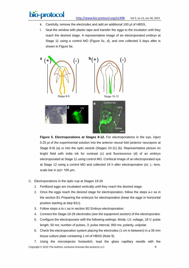
Figure 5. Electroporations at Stages 8-12. For electroporations in the eye, inject
0.25 µl of the experimental solution into the anterior neural fold (anterior neuropore at
Stage 8-9) (a) or into the optic vesicle (Stages 10-11) (b). Representative picture on
bright field with india ink for contrast (c) and fluorescence (d) of an embryo
electroporated at Stage 11 using control MO. Confocal image of an electroporated eye
at Stage 12 using a control MO and collected 24 h after electroporation (e). L: lens,
scale bar in (e)= 100 μm.
C. Electroporations in the optic cup at Stages 19-26
1. Fertilized eggs are incubated vertically until they reach the desired stage.
2. Once the eggs reach the desired stage for electroporation, follow the steps a-c as in
the section B1 Preparing the embryos for electroporation (keep the eggs in horizontal
position starting at step B1c).
3. Follow steps a to c as in section B2 Embryo electroporation.
4. Connect the Stage-19-26 electrodes (see the equipment section) of the electroporator.
5. Configure the electroporator with the following settings: Mode, LV; voltage, 18 V; pulse
length, 50 ms; number of pulses, 3; pulse interval, 950 ms; polarity, unipolar.
6. Check the electroporation system placing the electrodes (1 cm in between) in a 35 mm
tissue culture plate containing 1 ml of HBSS (Note 9).
7. Using the microinjector footswitch, load the glass capillary needle with the
http://www.bio-protocol.org/e1498 Vol 5, Iss 12, Jun 20, 2015
Copyright © 2015 The Authors; exclusive licensee Bio-protocol LLC. 10
experimental solution (RCAS-DNA or morpholinos).
8. For electroporations in the eye, inject 0.5 µl (40 microinjection pulses) into the eye cup
at Stage 18-19 or 0.75 µl (60 microinjection pulses) into the eye at Stage 24-25 using
a 20 µm diameter tip glass capillary needle.
9. Add 200 µl of HBSS to the embryo to decrease the resistance between the electrodes.
10. To perform the electroporation, the gold plated electrode connected to the anode (+) is
placed close to the ventro-temporal section of the eye and the cathode (-) electrode is
inserted perpendicular to the head of the embryo (Video 2 essentially describes steps
C8-10).
Video 2. Electroporation in the chick optic cup at Stages 19-26
11. Remove the electrodes carefully and add 200 µl of HBSS.
12. Seal the window with plastic tape and transfer the eggs to the incubator until they
reach the desired stage. A representative embryo electroporated at Stage 25 is shown
in Figure 6.
http://www.bio-protocol.org/e1498 Vol 5, Iss 12, Jun 20, 2015
Copyright © 2015 The Authors; exclusive licensee Bio-protocol LLC. 11
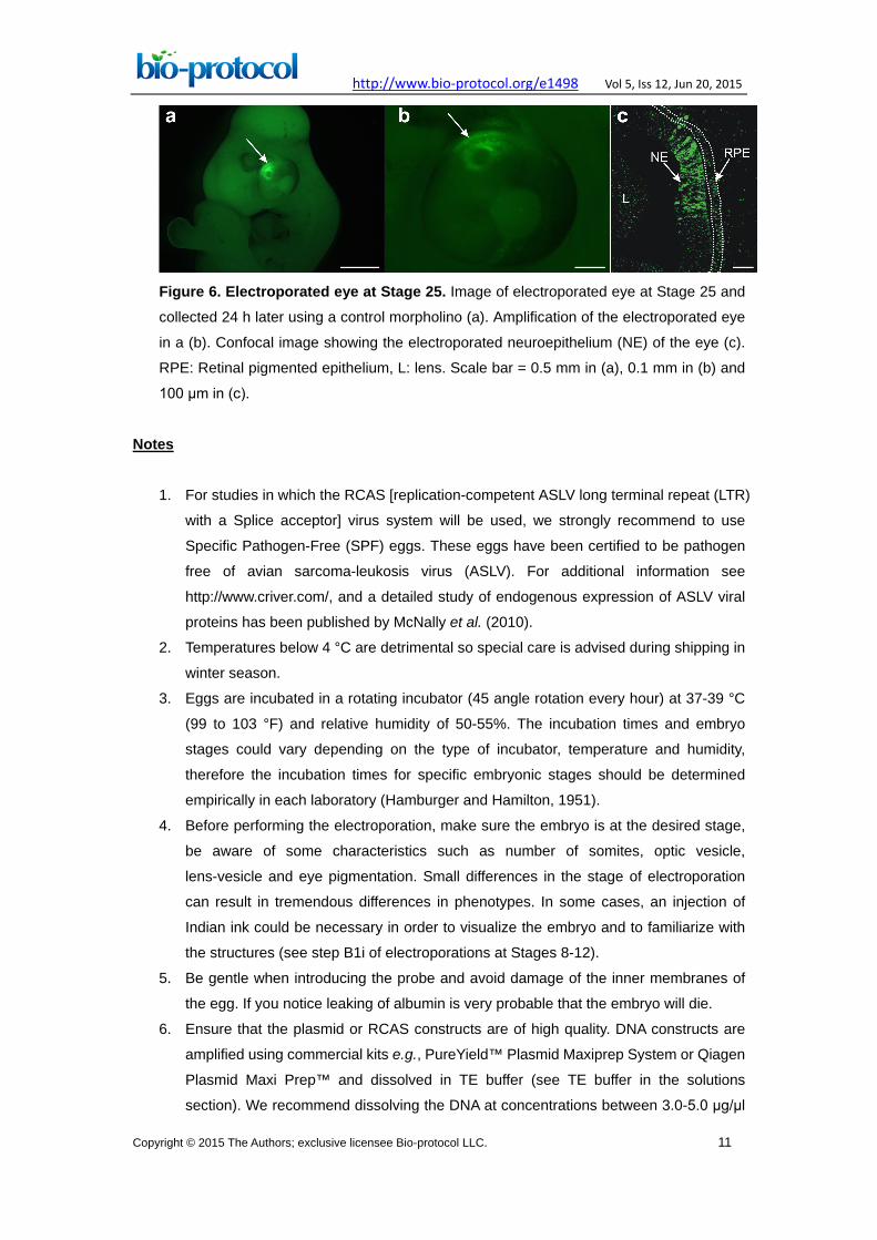
Figure 6. Electroporated eye at Stage 25. Image of electroporated eye at Stage 25 and
collected 24 h later using a control morpholino (a). Amplification of the electroporated eye
in a (b). Confocal image showing the electroporated neuroepithelium (NE) of the eye (c).
RPE: Retinal pigmented epithelium, L: lens. Scale bar = 0.5 mm in (a), 0.1 mm in (b) and
100 μm in (c).
Notes
1. For studies in which the RCAS [replication-competent ASLV long terminal repeat (LTR)
with a Splice acceptor] virus system will be used, we strongly recommend to use
Specific Pathogen-Free (SPF) eggs. These eggs have been certified to be pathogen
free of avian sarcoma-leukosis virus (ASLV). For additional information see
http://www.criver.com/, and a detailed study of endogenous expression of ASLV viral
proteins has been published by McNally et al. (2010).
2. Temperatures below 4 °C are detrimental so special care is advised during shipping in
winter season.
3. Eggs are incubated in a rotating incubator (45 angle rotation every hour) at 37-39 °C
(99 to 103 °F) and relative humidity of 50-55%. The incubation times and embryo
stages could vary depending on the type of incubator, temperature and humidity,
therefore the incubation times for specific embryonic stages should be determined
empirically in each laboratory (Hamburger and Hamilton, 1951).
4. Before performing the electroporation, make sure the embryo is at the desired stage,
be aware of some characteristics such as number of somites, optic vesicle,
lens-vesicle and eye pigmentation. Small differences in the stage of electroporation
can result in tremendous differences in phenotypes. In some cases, an injection of
Indian ink could be necessary in order to visualize the embryo and to familiarize with
the structures (see step B1i of electroporations at Stages 8-12).
5. Be gentle when introducing the probe and avoid damage of the inner membranes of
the egg. If you notice leaking of albumin is very probable that the embryo will die.
6. Ensure that the plasmid or RCAS constructs are of high quality. DNA constructs are
amplified using commercial kits e.g., PureYield™ Plasmid Maxiprep System or Qiagen
Plasmid Maxi Prep™ and dissolved in TE buffer (see TE buffer in the solutions
section). We recommend dissolving the DNA at concentrations between 3.0-5.0 μg/μl
http://www.bio-protocol.org/e1498 Vol 5, Iss 12, Jun 20, 2015
Copyright © 2015 The Authors; exclusive licensee Bio-protocol LLC. 12
for plasmids and 200 ng/μl for RCAS constructs and store at -20 °C for short-term use
or at -80 °C for long-term storage. Avoid using samples of DNA containing traces of
Phenol or ethanol and high concentration of salts, since they could be detrimental for
the viability of the embryo. Determine the concentration of DNA using a
spectrophotometer or a Nanodrop. Alternatively, the concentration could be
determined using SYBR Green I dsDNA assay. The ratio of absorbance 260/280 will
give you an idea about the purity of DNA vs protein or other contaminants and
secondary measurement could be 260/230 (phenol carbohydrates and have
absorbance close to 230nm) (see technical support bulletin at
http://www.bio.davidson.edu/projects/gcat/protocols/NanoDrop_tip.pdf). A ratio of ~1.8
or above for 260/280 ratio or 2.0-2.2 for 260/230 are considered good quality DNA.
Always verify the integrity of the DNA by electrophoresis. Quantification is not enough
to ensure that your DNA is of good quality. For first time users, it is advisable to use
plasmids containing a reporter gene such as GFP to evaluate the efficiency of
electroporation, for example pCAG-GFP or pEGFP-N1. Additionally, in order to track
the expression of your gene of interest it is recommendable to design your constructs
to include an IRES-GFP sequence or an alternative way to identify the electroporated
areas. To prepare the electroporation solution, mix 9.0 μl of plasmid (3.0-5.0 μg/μl) or
RCAS-contruct (200 ng/μl) with 1 μl of 0.05% Fast Green dye.
7. Morpholino (MO) antisense oligonucleotides are designed to down regulate gene
expression. They can be designed and ordered from GeneTools LLC
(http://www.gene-tools.com/). In order to trace the electroporated cells, the MOs must
be tagged at the 3’-end (e.g., carboxyfluorescein). MO have minimal off-target effects
but it is recommendable to use at least two different MOs (e.g., to block translation and
splice junctions) in order to observe the same phenotypic effects. Additionally, it is
necessary to use a control MO and/or scrambled sequence of the target mRNA. The
main disadvantages of using MOs is that they are very expensive and sometimes it is
necessary to test more than two sequences in order to find the right MO to efficiently
down regulate gene expression. Moreover, during cell division, MOs are diluted so
they are inefficient for long term (more than 4 days) and in some cases they are
practically undetectable after 72 h of electroporation and in such cases the
fluorescence signal needs to be detected using an antibody against fluorescein. MOs
are dissolved at 1 mM concentration using sterile Ringer’s solution and stored at room
temperature in the original container and kept in the dark. According with Gene Tools,
MOs can precipitate at low temperatures and lose their efficiency, so they need to be
resuspended again before use. During electroporation, MOs can migrate slightly
towards the anode (+) possibly because of the fluorescein that is negatively charged.
In order to increase the efficiency of MO electroporation, it is advisable to use 0.5 μg of
DNA (e.g., non-biologically active plasmid). To prepare the electroporation solution,
mix and heat an aliquot of 10 μl at 65 °C for 10 min to re-dissolve the precipitates. It is
http://www.bio-protocol.org/e1498 Vol 5, Iss 12, Jun 20, 2015
Copyright © 2015 The Authors; exclusive licensee Bio-protocol LLC. 13
not recommendable to use fast green since it can inhibit the electroporation (Kos et al.,
2013). The injection of the carboxyfluorescein-tagged morpholino can be visualized
using a blue dichroic filter attached to a regular fiber optic lamp.
8. We provided the list of parts necessary to set up Stage-8-12 and Stage-19-26
electrodes, notice that some of the parts listed could be the same.
9. You will see gentle bubbling on the electrodes after pushing the electroporator
footswitch, (the bubbling is an indication that the system is working properly).
Recipes
1. Ringer’s solution
a. Dissolve 7.2 g NaCl, 0.17 g CaCl2, 0.37 g KCl, 0.115 g Na2HPO4, and 0.02 g
KH2PO4 in 900 ml of deionized water
b. Adjust pH to 7.2 using HCl and bring to 1 L with deionized water
Note: Final concentration: NaCl 123 mM, CaCl2 1.53 mM, KCl 5 mM, Na2HPO4 0.8
mM, KH2PO4 0.1 mM.
c. Sterilized by filtration using a 0.2 μm Corning disposable plastic vacuum filter
d. Freeze aliquots of 10 ml at -20 °C
2. 10x Hank's balanced salt solution (HBSS)
a. Prepare 250 ml of 1x HBSS using deionized water and adjust pH to 7.2
b. Sterilize by filtration using a 0.2 μm Corning disposable plastic vacuum filters
c. Freeze aliquots of 10 ml at -20 °C
3. Fast green FCF
a. Prepare a stock solution of 0.05% (wt/vol) using deionized water
b. Sterilize by filtration using a 0.2 μm Corning syringe disc-type filters
4. 1 M Tris
Dissolve 6.057g Tris in 30.0 ml of deionized water andadjust the pH to 8.0 using 1 N
HCl and bring to 50.0 ml with deionized water.
5. 0.5 M EDTA
Dissolve 18.6 g in 80.0 ml deionized water and adjust the pH to 8.0 using 10 N NaOH
(EDTA is soluble until pH reaches 8.0), bring to 100.0 with deionized water.
6. TE buffer for plasmid solutions (10 mM Tris, 1 mM EDTA, pH=8)
To prepare 50 ml of TE buffer combine 0.5 ml of 1 M Tris (pH=8) with 0.1 ml of 0.5 M
EDTA (pH=8) and adjust to 50 ml with deionized water
Sterilize by autoclave and freeze aliquots of 2 ml at -20 °C
Acknowledgments
Michael Weeks, Jayson Alexander and Bill Lack, Instrumentation Laboratory at Miami
University for their help in the electrodes set up, Leah Stetzel her help on the video

http://www.bio-protocol.org/e1498 Vol 5, Iss 12, Jun 20, 2015
Copyright © 2015 The Authors; exclusive licensee Bio-protocol LLC. 14
recording. This work was supported by EY17319 to KDRT, and CONACYT 162930 and
142523 to AL-M. This protocol has been adapted from our previous publications
Luz-Madrigal et al. (2014) and Zhu et al. (2014).
References
1. Hamburger, V. and Hamilton, H. L. (1951). A series of normal stages in the
development of the chick embryo. J Morphol 88(1): 49-92.
2. Kos, R., Tucker, R. P., Hall, R., Duong, T. D. and Erickson, C. A. (2003). Methods for
introducing morpholinos into the chicken embryo. Dev Dyn 226(3): 470-477.
3. Luz-Madrigal, A., Grajales-Esquivel, E., McCorkle, A., DiLorenzo, A. M.,
Barbosa-Sabanero, K., Tsonis, P. A. and Del Rio-Tsonis, K. (2014). Reprogramming
of the chick retinal pigmented epithelium after retinal injury. BMC Biol 12: 28.
4. McNally, M. M., Wahlin, K. J. and Canto-Soler, M. V. (2010). Endogenous expression
of ASLV viral proteins in specific pathogen free chicken embryos: relevance for the
developmental biology research field. BMC Dev Biol 10: 106.
5. Zhu, J., Luz-Madrigal, A., Haynes, T., Zavada, J., Burke, A. K. and Del Rio-Tsonis, K.
(2014). beta-Catenin inactivation is a pre-requisite for chick retina regeneration. PLoS
One 9(7): e101748.