Embed Size (px)
Citation preview
1
Electronics Technology and Robotics III Basic Pneumatics
Administration:
o Prayer Introduction: The reason for using pneumatics, or any other type of
energy transmission on a machine, is to perform work. In a pneumatic system, energy is stored (potential energy) under the form of compressed air. Working energy (kinetic energy) results in a pneumatic system when the compressed air is allowed to expand.
Parts of a Pneumatic System: o Compressor:
As gases are compressible, a gas compressor is a mechanical device that increases the pressure of a gas by reducing its volume.
There are two basic compressor layouts, horizontal tank or vertical tank with the pump and motor mounted on a bracket welded on top of the tank.
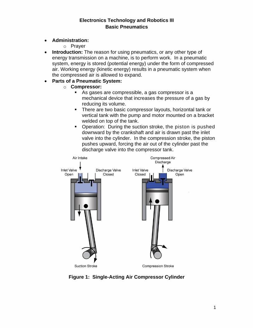
Operation: During the suction stroke, the piston is pushed downward by the crankshaft and air is drawn past the inlet valve into the cylinder. In the compression stroke, the piston pushes upward, forcing the air out of the cylinder past the discharge valve into the compressor tank.
Figure 1: Single-Acting Air Compressor Cylinder
2
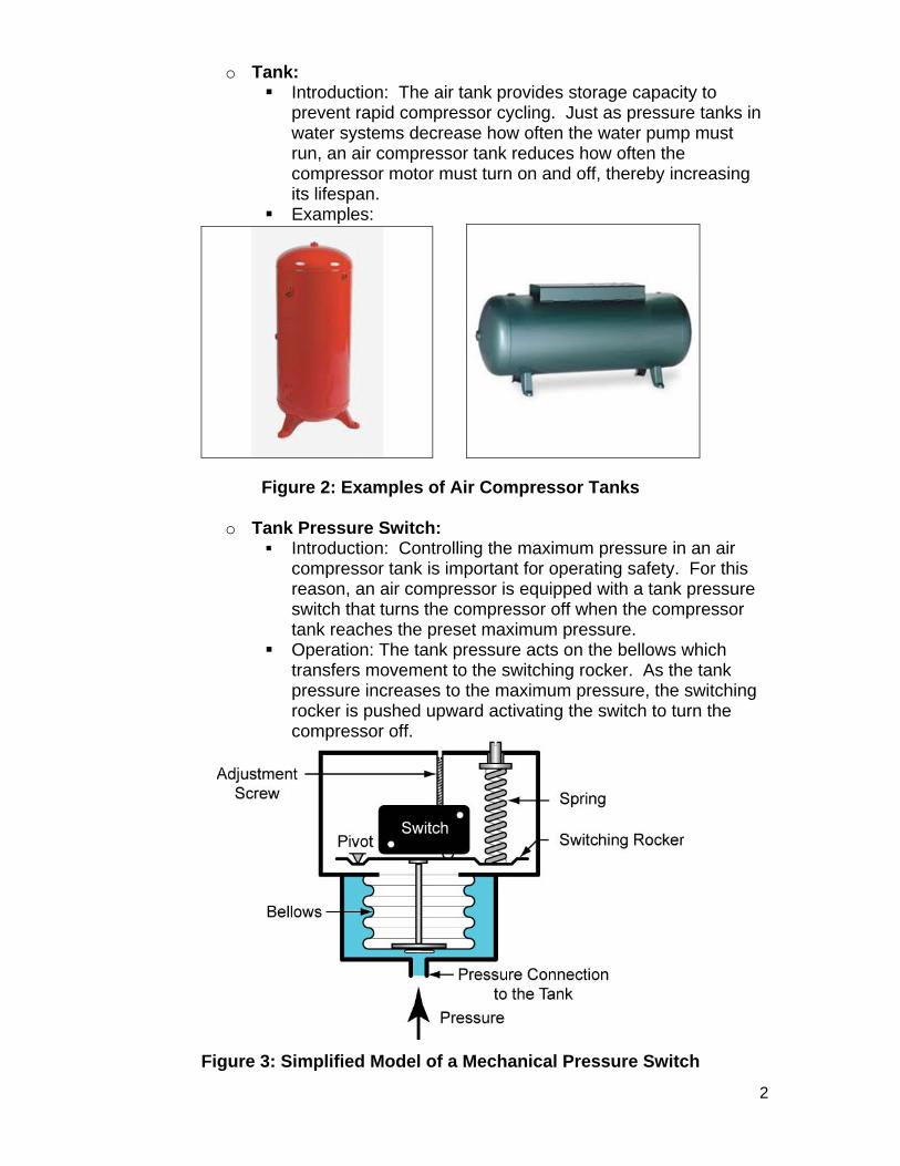
o Tank: Introduction: The air tank provides storage capacity to
prevent rapid compressor cycling. Just as pressure tanks in water systems decrease how often the water pump must run, an air compressor tank reduces how often the compressor motor must turn on and off, thereby increasing its lifespan.
Examples:
Figure 2: Examples of Air Compressor Tanks
o Tank Pressure Switch: Introduction: Controlling the maximum pressure in an air
compressor tank is important for operating safety. For this reason, an air compressor is equipped with a tank pressure switch that turns the compressor off when the compressor tank reaches the preset maximum pressure.
Operation: The tank pressure acts on the bellows which transfers movement to the switching rocker. As the tank pressure increases to the maximum pressure, the switching rocker is pushed upward activating the switch to turn the compressor off.
Figure 3: Simplified Model of a Mechanical Pressure Switch
3
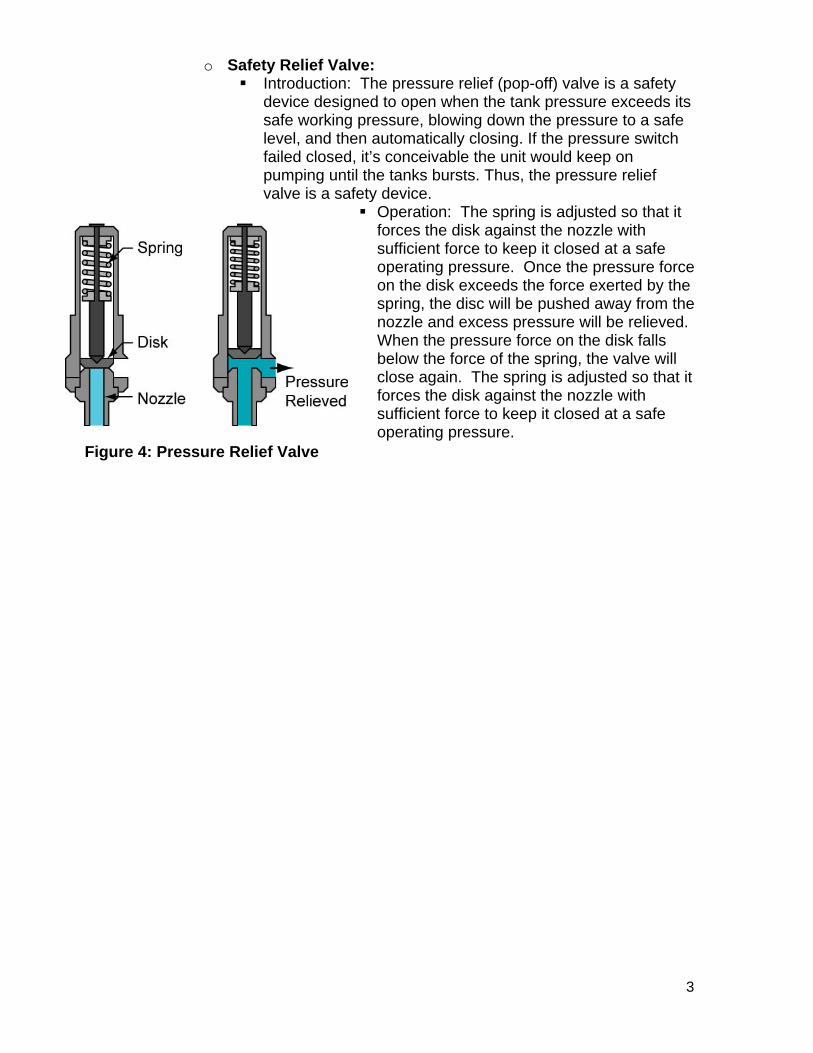
o Safety Relief Valve: Introduction: The pressure relief (pop-off) valve is a safety
device designed to open when the tank pressure exceeds its safe working pressure, blowing down the pressure to a safe level, and then automatically closing. If the pressure switch failed closed, it’s conceivable the unit would keep on pumping until the tanks bursts. Thus, the pressure relief valve is a safety device.
Operation: The spring is adjusted so that it forces the disk against the nozzle with sufficient force to keep it closed at a safe operating pressure. Once the pressure force on the disk exceeds the force exerted by the spring, the disc will be pushed away from the nozzle and excess pressure will be relieved. When the pressure force on the disk falls below the force of the spring, the valve will close again. The spring is adjusted so that it forces the disk against the nozzle with sufficient force to keep it closed at a safe operating pressure.
Figure 4: Pressure Relief Valve
4
o Pressure Regulator: Introduction: A pressure regulator controls the air pressure
coming out of the tank to provide consistent pressure. There are two basic types of regulator - single stage and
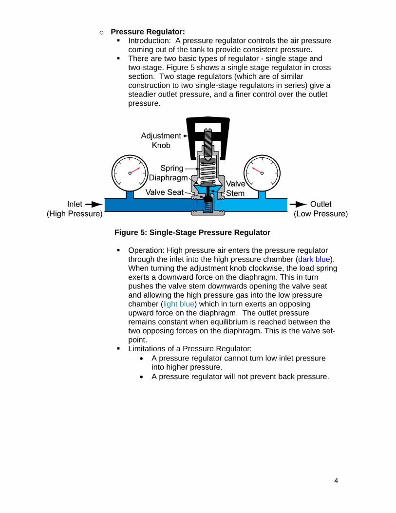
two-stage. Figure 5 shows a single stage regulator in cross section. Two stage regulators (which are of similar construction to two single-stage regulators in series) give a steadier outlet pressure, and a finer control over the outlet pressure.
Figure 5: Single-Stage Pressure Regulator
Operation: High pressure air enters the pressure regulator through the inlet into the high pressure chamber (dark blue). When turning the adjustment knob clockwise, the load spring exerts a downward force on the diaphragm. This in turn pushes the valve stem downwards opening the valve seat and allowing the high pressure gas into the low pressure chamber (light blue) which in turn exerts an opposing upward force on the diaphragm. The outlet pressure remains constant when equilibrium is reached between the two opposing forces on the diaphragm. This is the valve set-point.
Limitations of a Pressure Regulator: A pressure regulator cannot turn low inlet pressure
into higher pressure. A pressure regulator will not prevent back pressure.
5
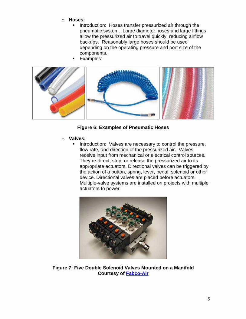
o Hoses: Introduction: Hoses transfer pressurized air through the
pneumatic system. Large diameter hoses and large fittings allow the pressurized air to travel quickly, reducing airflow backups. Reasonably large hoses should be used depending on the operating pressure and port size of the components.
Examples:
Figure 6: Examples of Pneumatic Hoses
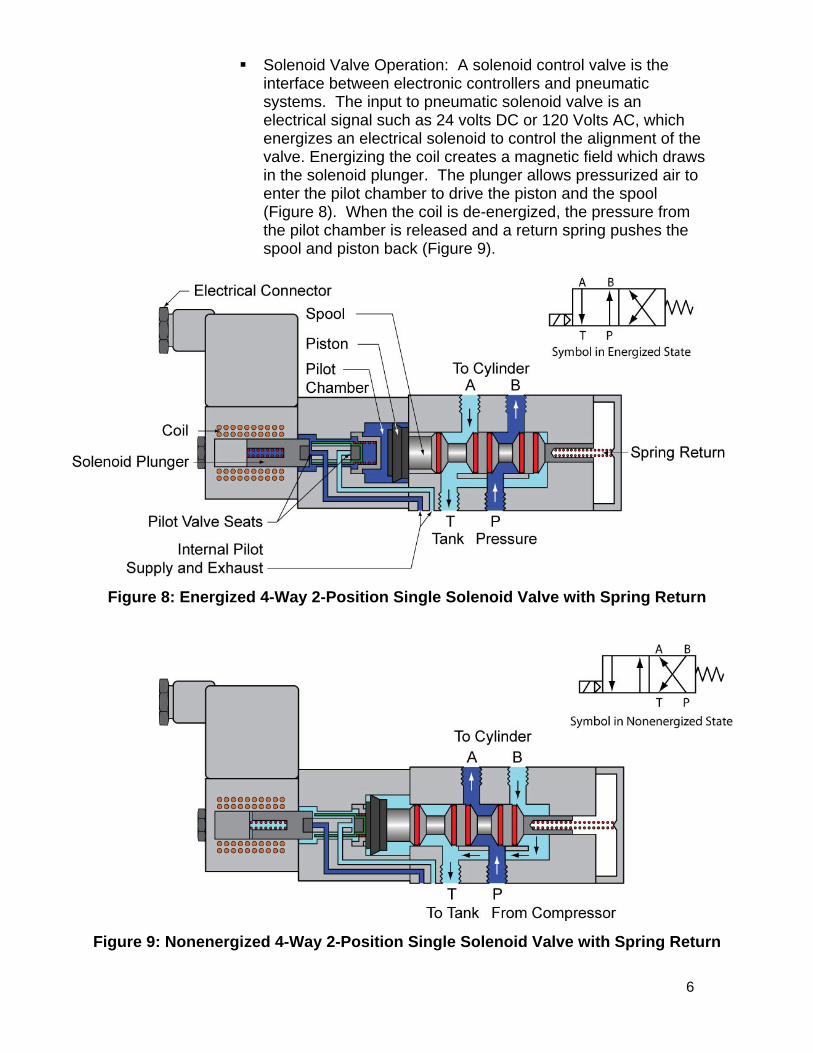
o Valves: Introduction: Valves are necessary to control the pressure,
flow rate, and direction of the pressurized air. Valves receive input from mechanical or electrical control sources. They re-direct, stop, or release the pressurized air to its appropriate actuators. Directional valves can be triggered by the action of a button, spring, lever, pedal, solenoid or other device. Directional valves are placed before actuators. Multiple-valve systems are installed on projects with multiple actuators to power.
Figure 7: Five Double Solenoid Valves Mounted on a Manifold Courtesy of Fabco-Air
6
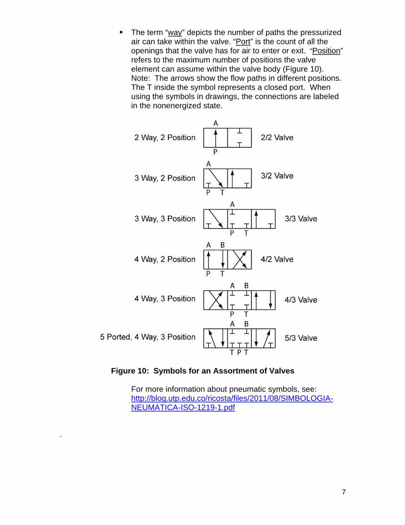
Solenoid Valve Operation: A solenoid control valve is the interface between electronic controllers and pneumatic systems. The input to pneumatic solenoid valve is an electrical signal such as 24 volts DC or 120 Volts AC, which energizes an electrical solenoid to control the alignment of the valve. Energizing the coil creates a magnetic field which draws in the solenoid plunger. The plunger allows pressurized air to enter the pilot chamber to drive the piston and the spool (Figure 8). When the coil is de-energized, the pressure from the pilot chamber is released and a return spring pushes the spool and piston back (Figure 9).
Figure 8: Energized 4-Way 2-Position Single Solenoid Valve with Spring Return
Figure 9: Nonenergized 4-Way 2-Position Single Solenoid Valve with Spring Return
7
The term “way” depicts the number of paths the pressurized air can take within the valve. “Port” is the count of all the openings that the valve has for air to enter or exit. “Position” refers to the maximum number of positions the valve element can assume within the valve body (Figure 10). Note: The arrows show the flow paths in different positions. The T inside the symbol represents a closed port. When using the symbols in drawings, the connections are labeled in the nonenergized state.
Figure 10: Symbols for an Assortment of Valves
For more information about pneumatic symbols, see: http://blog.utp.edu.co/ricosta/files/2011/08/SIMBOLOGIA-NEUMATICA-ISO-1219-1.pdf
.
8
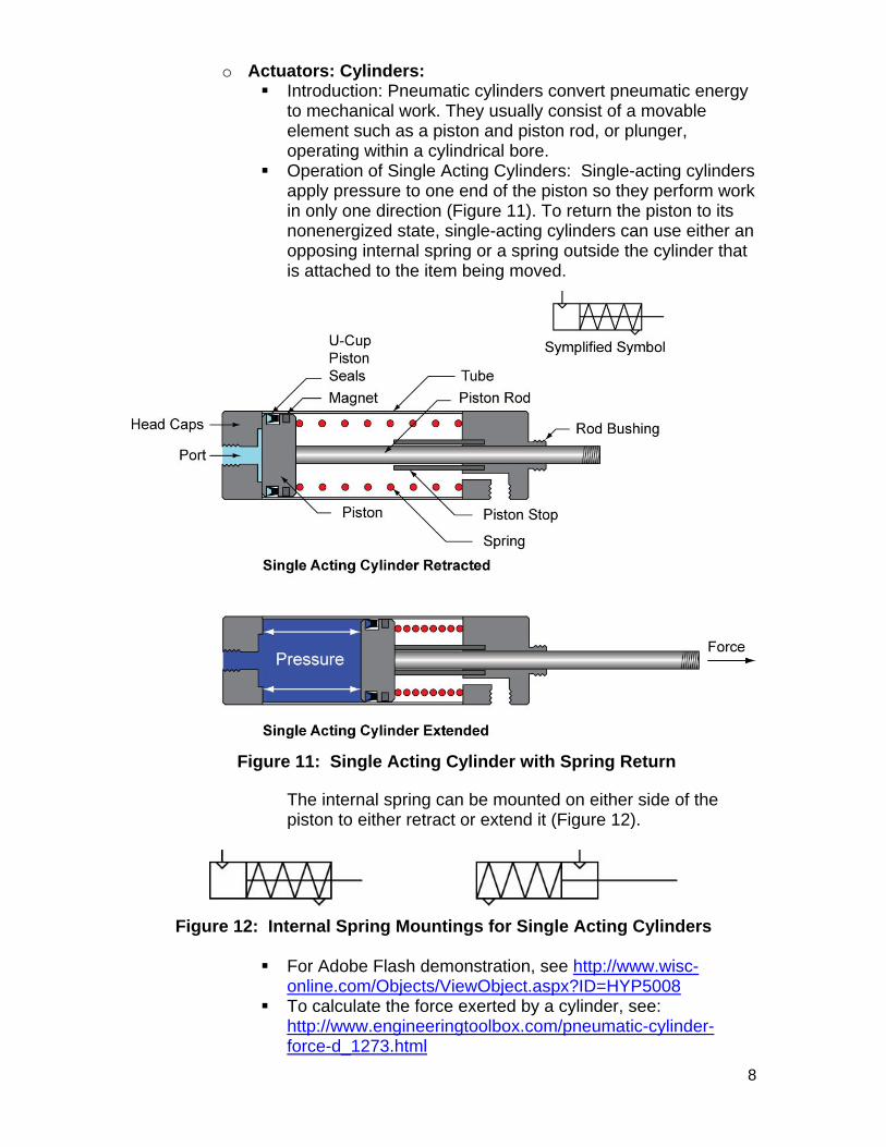
o Actuators: Cylinders: Introduction: Pneumatic cylinders convert pneumatic energy
to mechanical work. They usually consist of a movable element such as a piston and piston rod, or plunger, operating within a cylindrical bore.
Operation of Single Acting Cylinders: Single-acting cylinders apply pressure to one end of the piston so they perform work in only one direction (Figure 11). To return the piston to its nonenergized state, single-acting cylinders can use either an opposing internal spring or a spring outside the cylinder that is attached to the item being moved.
Figure 11: Single Acting Cylinder with Spring Return
The internal spring can be mounted on either side of the piston to either retract or extend it (Figure 12).
Figure 12: Internal Spring Mountings for Single Acting Cylinders
For Adobe Flash demonstration, see http://www.wisc-online.com/Objects/ViewObject.aspx?ID=HYP5008
To calculate the force exerted by a cylinder, see: http://www.engineeringtoolbox.com/pneumatic-cylinder-force-d_1273.html
9
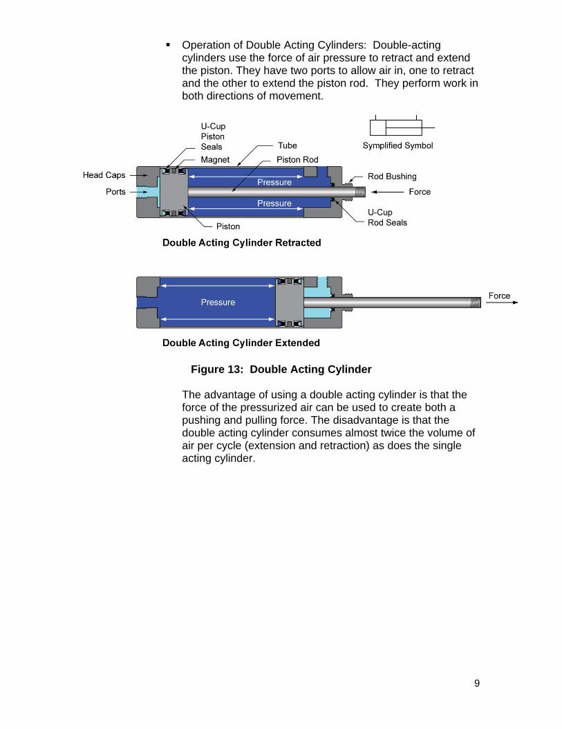
Operation of Double Acting Cylinders: Double-acting cylinders use the force of air pressure to retract and extend the piston. They have two ports to allow air in, one to retract and the other to extend the piston rod. They perform work in both directions of movement.
Figure 13: Double Acting Cylinder
The advantage of using a double acting cylinder is that the force of the pressurized air can be used to create both a pushing and pulling force. The disadvantage is that the double acting cylinder consumes almost twice the volume of air per cycle (extension and retraction) as does the single acting cylinder.
10
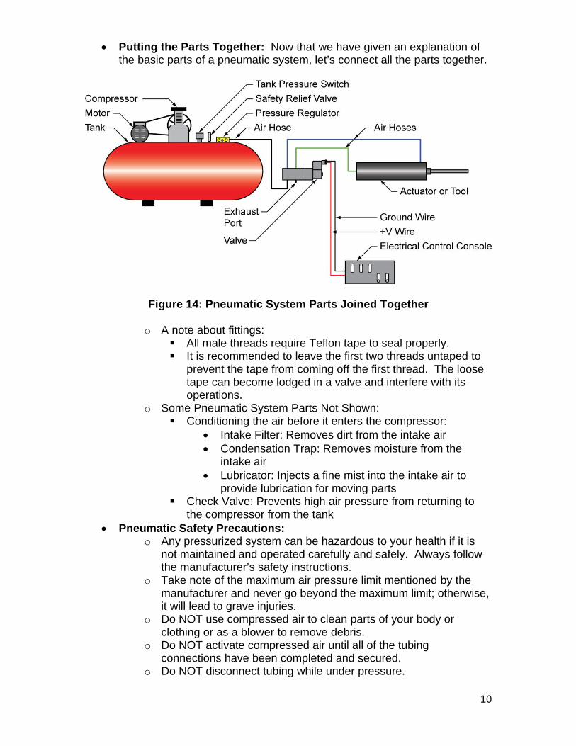
Putting the Parts Together: Now that we have given an explanation of the basic parts of a pneumatic system, let’s connect all the parts together.
Figure 14: Pneumatic System Parts Joined Together
o A note about fittings: All male threads require Teflon tape to seal properly. It is recommended to leave the first two threads untaped to
prevent the tape from coming off the first thread. The loose tape can become lodged in a valve and interfere with its operations.
o Some Pneumatic System Parts Not Shown: Conditioning the air before it enters the compressor:
Intake Filter: Removes dirt from the intake air Condensation Trap: Removes moisture from the
intake air Lubricator: Injects a fine mist into the intake air to
provide lubrication for moving parts Check Valve: Prevents high air pressure from returning to
the compressor from the tank Pneumatic Safety Precautions:
o Any pressurized system can be hazardous to your health if it is not maintained and operated carefully and safely. Always follow the manufacturer’s safety instructions.
o Take note of the maximum air pressure limit mentioned by the manufacturer and never go beyond the maximum limit; otherwise, it will lead to grave injuries.
o Do NOT use compressed air to clean parts of your body or clothing or as a blower to remove debris.
o Do NOT activate compressed air until all of the tubing connections have been completed and secured.
o Do NOT disconnect tubing while under pressure.
11
o NEVER attempt to stop or repair a leak while the leaking portion is still under pressure. Always depressurize the system before making the repair.
o Avoid the application of heat to the air piping system or components, and avoid striking a sharp, heavy blow on any pressurized part of the piping system.
o Always wear safety goggles when you are connecting and operating circuits.
o Check that all airlines are connected before turning on the main air supply.
o Always turn off the main air supply before changing a circuit. o Keep your hands away from moving pneumatic parts. o Avoid having airlines trailing across the floor or where someone
could trip or become entangled. Maintenance:
o Check the compressor and actuator or tool operating manuals for the routine maintenance schedule.
o As the air is compressed, the water vapor contained in the atmosphere is compressed along with it; the increased pressure causes much of the water vapor in the air to condense and drop out in a liquid form. The main enemy of pneumatic equipment is this water and the rust it causes. Air under pressure accelerates rust in a bare steel tank. Frequent draining of accumulated water is the best protection against rust. The compressor should be drained after every use.
Recommended Links: o http://www.scribd.com/doc/40148786/Pneumatics-Festo-Didactic o http://www.scribd.com/doc/39451207/Pneumatic-Basic-in-
Designing-Control-Circuit o http://www.scribd.com/doc/82929999/Hydraulics-Pneumatics
12
Technology and Robotics III Pneumatics Lab 1 – Basic Pneumatic Circuit
Purpose: The student constructs a simple pneumatic circuit and then designs and assembles three different control systems to run the pneumatic circuit.
Apparatus and Materials: o 1 – Air Compressor o 1 – 4-Way 2-Position Double Solenoid Pneumatic Valve with ¼”
Push-to-Connect Fittings o 1 – Double Acting Pneumatic Cylinder with ¼” Push-to-Connect
Fittings o ¼” Hose o Electrical and Fiber-Optic Equipment – To Be Determined
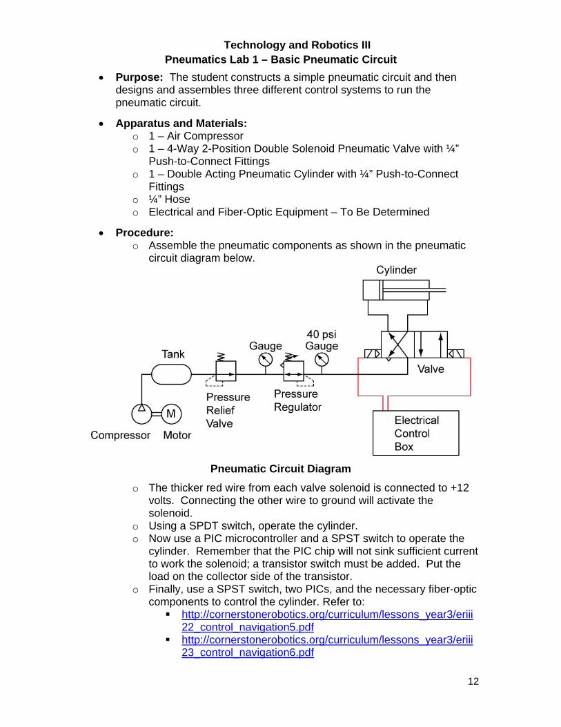
Procedure: o Assemble the pneumatic components as shown in the pneumatic
circuit diagram below.
Pneumatic Circuit Diagram
o The thicker red wire from each valve solenoid is connected to +12 volts. Connecting the other wire to ground will activate the solenoid.
o Using a SPDT switch, operate the cylinder. o Now use a PIC microcontroller and a SPST switch to operate the
cylinder. Remember that the PIC chip will not sink sufficient current to work the solenoid; a transistor switch must be added. Put the load on the collector side of the transistor.
o Finally, use a SPST switch, two PICs, and the necessary fiber-optic components to control the cylinder. Refer to: http://cornerstonerobotics.org/curriculum/lessons_year3/eriii
22_control_navigation5.pdf http://cornerstonerobotics.org/curriculum/lessons_year3/eriii
23_control_navigation6.pdf