Embed Size (px)
DESCRIPTION
Lecture of electronics about sensors.
Citation preview

Welcome
L/O/G/O
Sensing the world
Product Dynamics, L-E-2, Sensors
IO2022
Prof. Dr. Ir. J.M.P Geraedts
Dr. Y. Song, Martin Verwaal, Adrie Kooijman, Ir. Sander Minnoye
Faculty of Industrial Design Engineering
Delft University of Technology
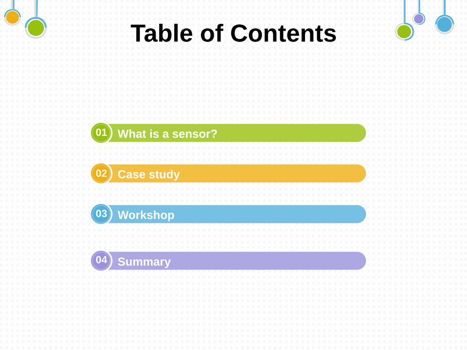
Table of Contents
What is a sensor?
Case study
Workshop
Summary
01
02
03
04
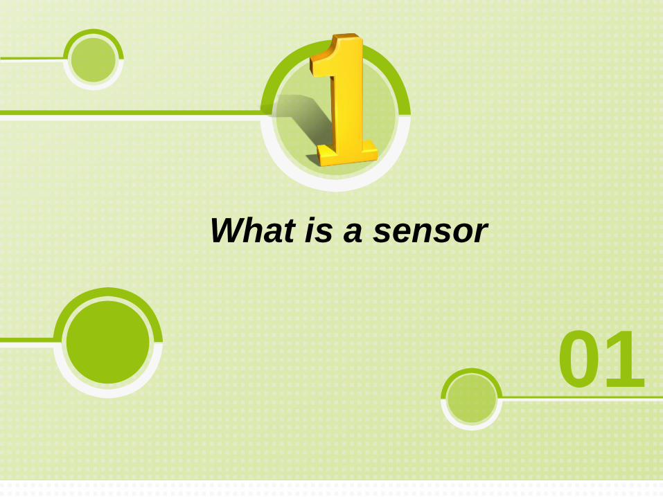
What is a sensor
01
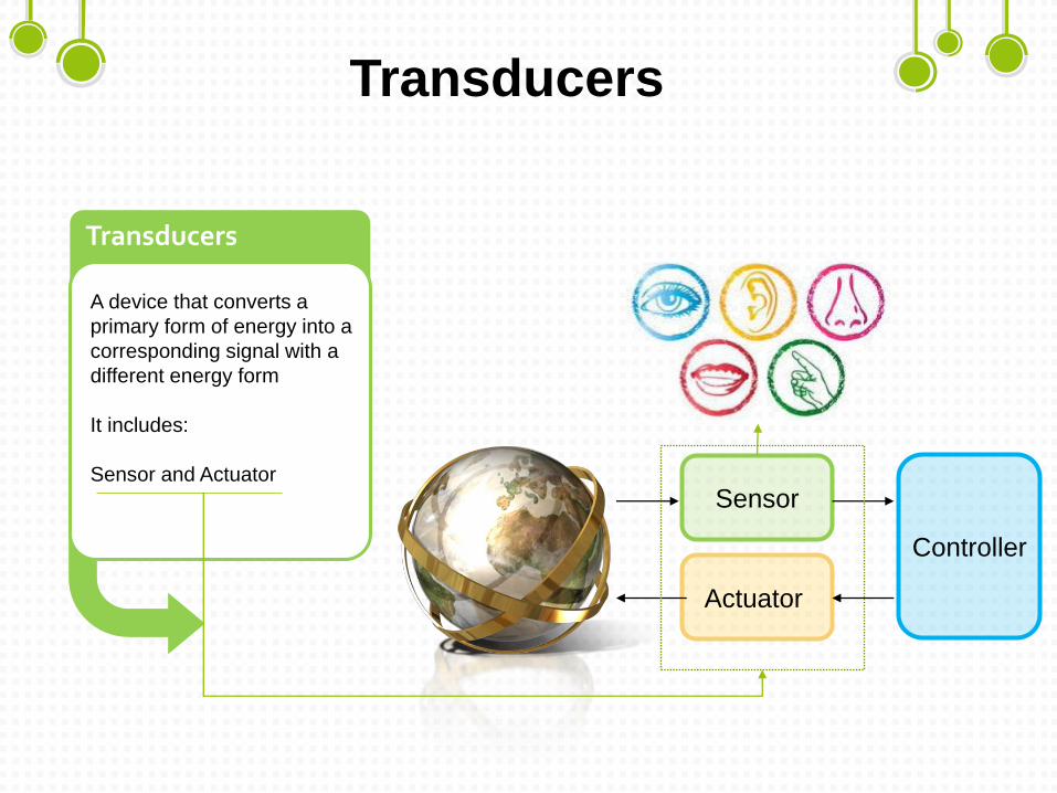
Transducers
A device that converts a
primary form of energy into a
corresponding signal with a
different energy form
It includes:
Sensor and Actuator
Transducers
Sensor
Actuator
Controller
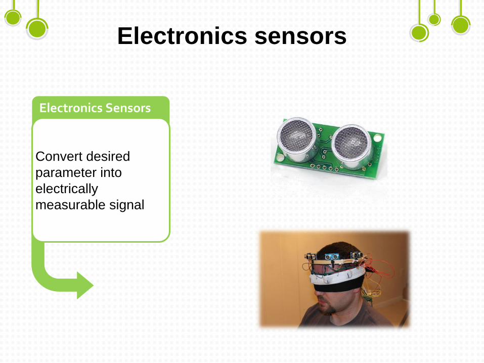
Electronics sensors
Convert desired
parameter into
electrically
measurable signal
Electronics Sensors
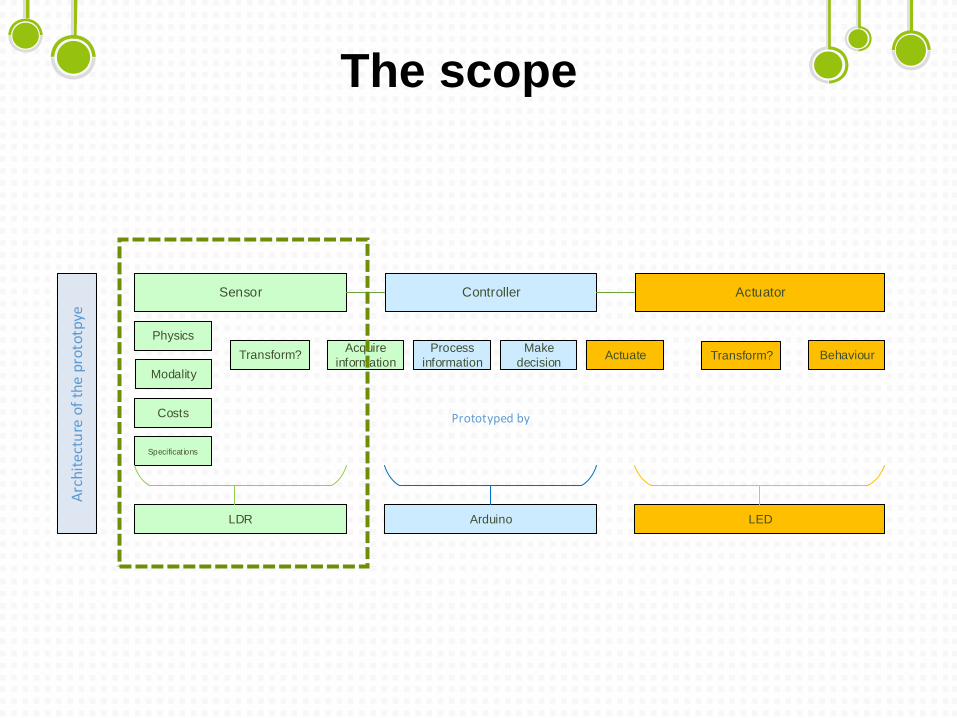
The scopeA
rch
ite
ctu
re o
f th
e p
roto
tpye
Sensor Controller Actuator
Physics
Modality
Specificat ions
Costs
Behaviour Transform?Acquire
information
Process
information
Make
decision
LDR LEDArduino
Prototyped by
ActuateTransform?
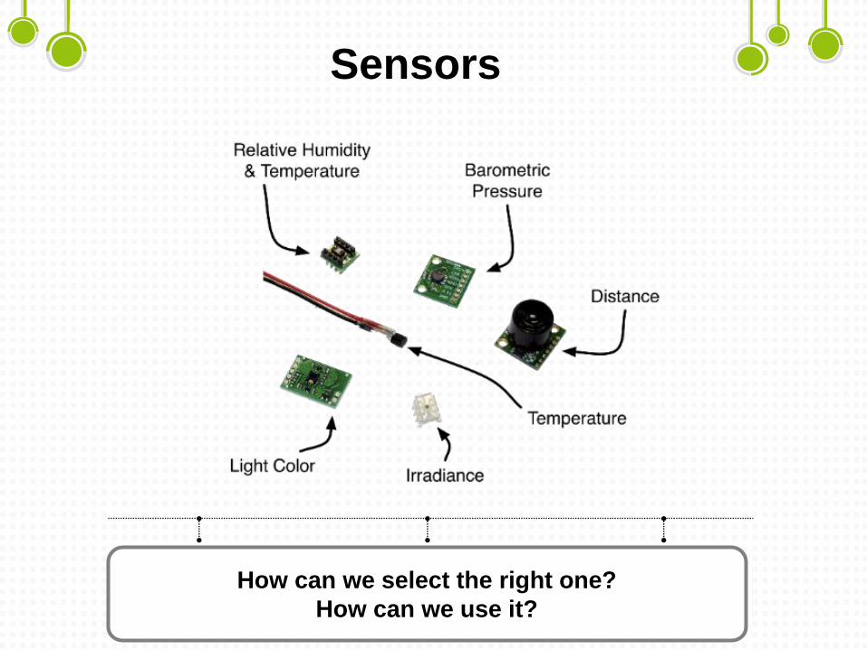
Sensors
How can we select the right one?
How can we use it?
Case study
02
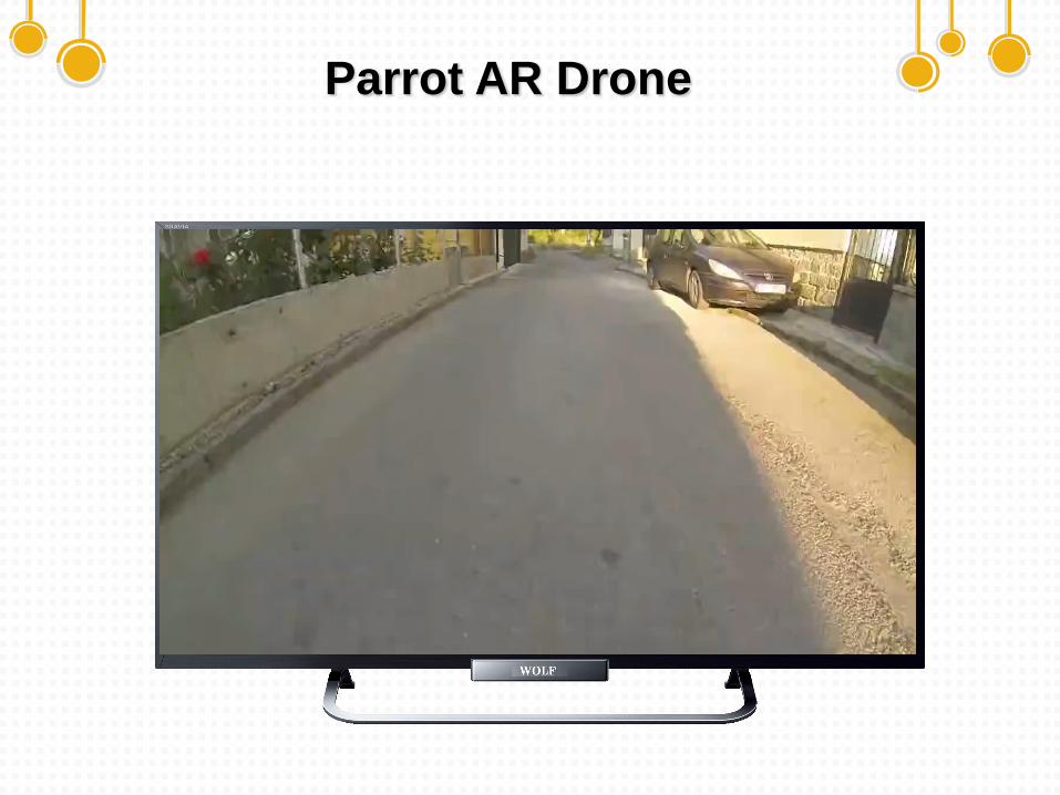
Parrot AR Drone
Case study
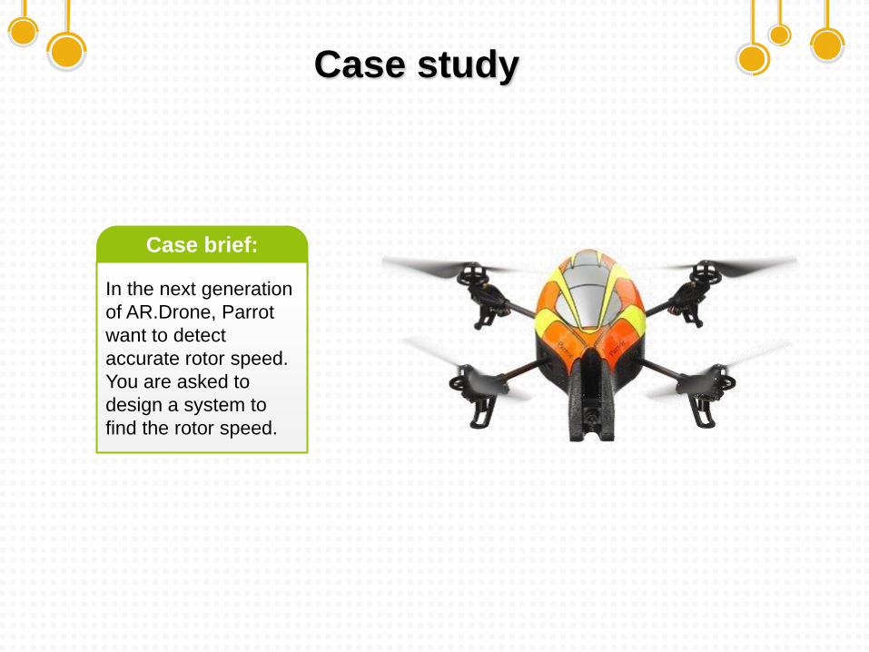
In the next generation
of AR.Drone, Parrot
want to detect
accurate rotor speed.
You are asked to
design a system to
find the rotor speed.
Case brief:
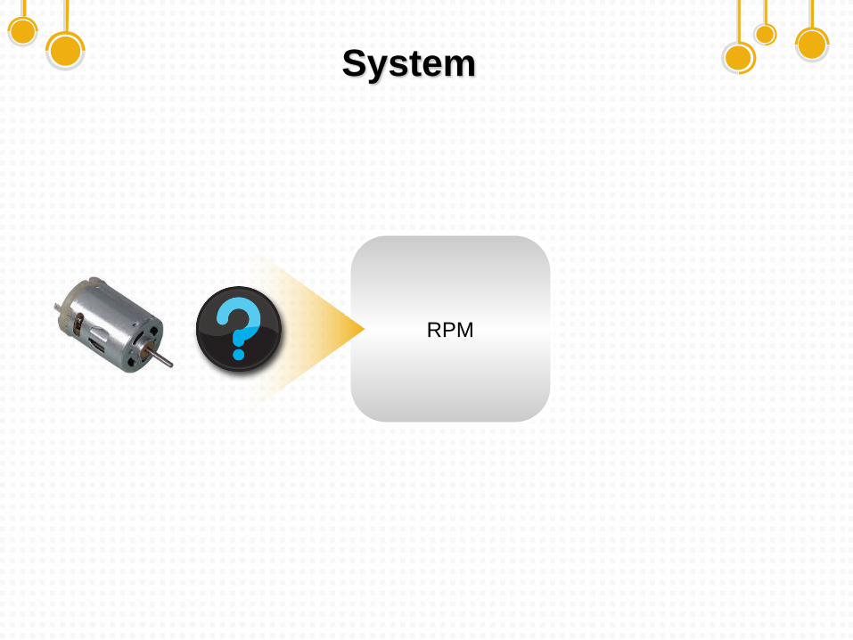
System
RPM
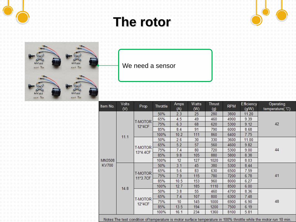
The rotor
We need a sensor
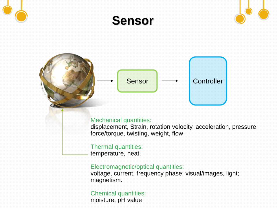
Sensor
Sensor Controller
Mechanical quantities: displacement, Strain, rotation velocity, acceleration, pressure, force/torque, twisting, weight, flow
Thermal quantities: temperature, heat.
Electromagnetic/optical quantities: voltage, current, frequency phase; visual/images, light; magnetism.
Chemical quantities: moisture, pH value
Attributes of Sensors
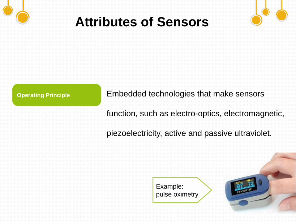
Embedded technologies that make sensors
function, such as electro-optics, electromagnetic,
piezoelectricity, active and passive ultraviolet.
Operating Principle
Example:
pulse oximetry
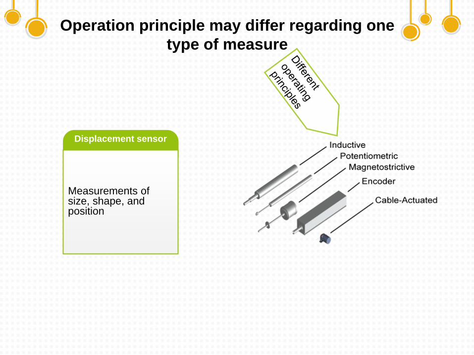
Operation principle may differ regarding one
type of measure
Measurements of size, shape, and position
Displacement sensor
Attributes of Sensors
The number of dimensions of physical variables.
The physical volume of sensors.
The measuring feature of data in time;
continuous or discrete/analog or digital.
Dimension of Variables
Size
Data Format
Attributes of Sensors
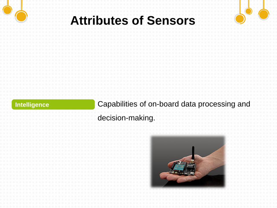
Capabilities of on-board data processing and
decision-making.
Intelligence
Attributes of Sensors
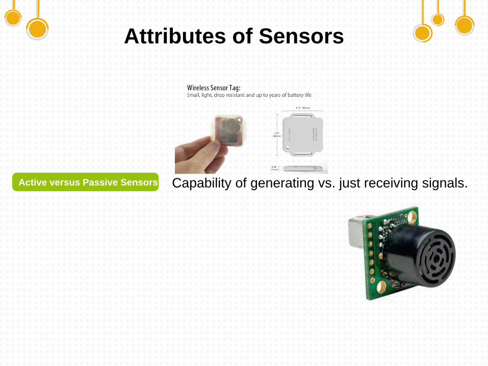
Capability of generating vs. just receiving signals.Active versus Passive Sensors
Attributes of Sensors
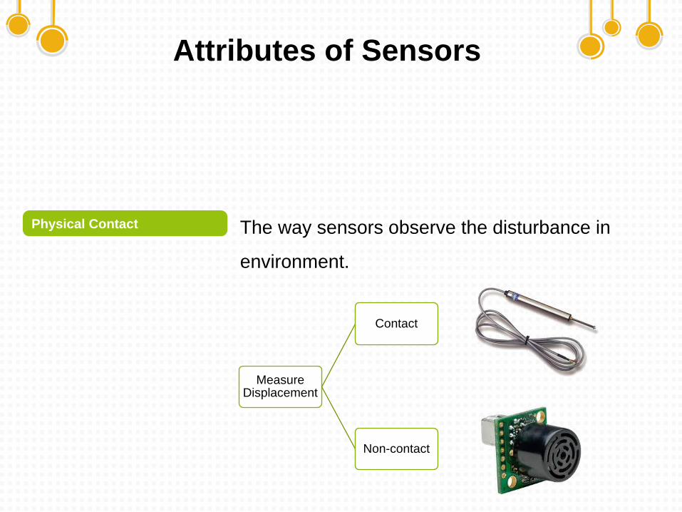
The way sensors observe the disturbance in
environment.
Physical Contact
Measure Displacement
Contact
Non-contact
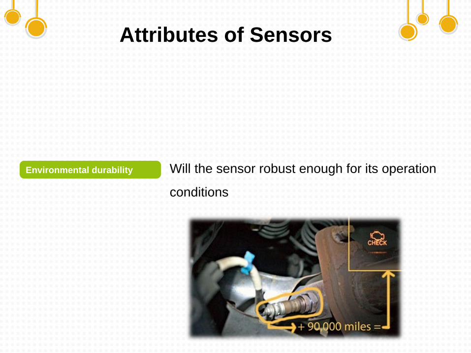
Attributes of Sensors
Will the sensor robust enough for its operation
conditions
Environmental durability
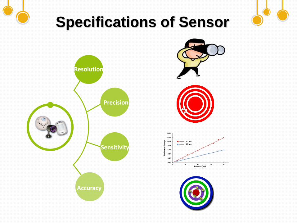
Specifications of Sensor
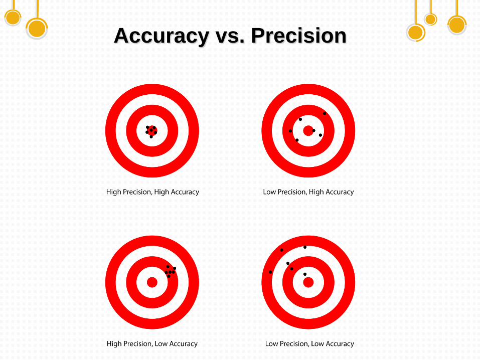
Accuracy
Text
Precision
Resolution
Sensitivity
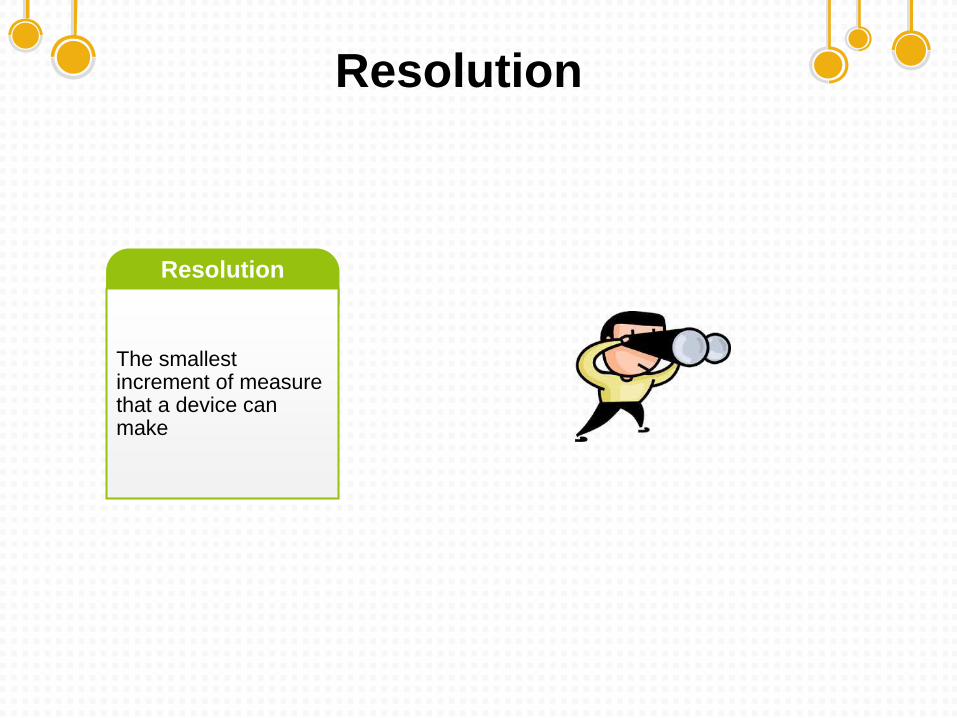
Resolution
The smallest increment of measure that a device can make
Resolution
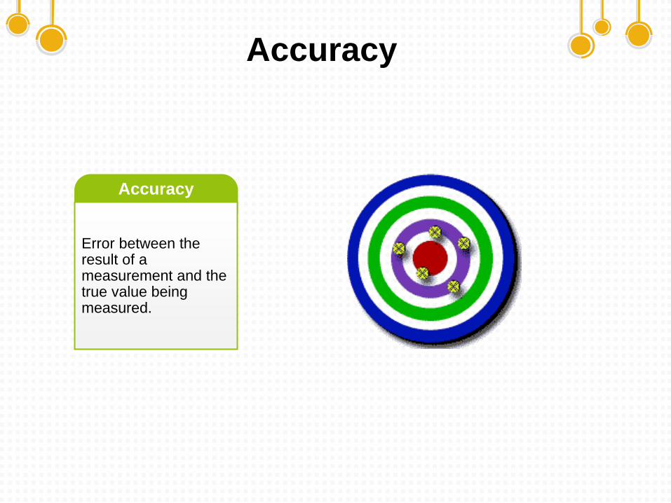
Accuracy
Error between the result of a measurement and the true value being measured.
Accuracy
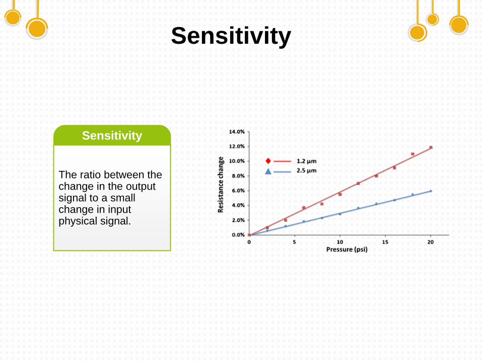
Sensitivity
The ratio between the change in the output signal to a small change in input physical signal.
Sensitivity
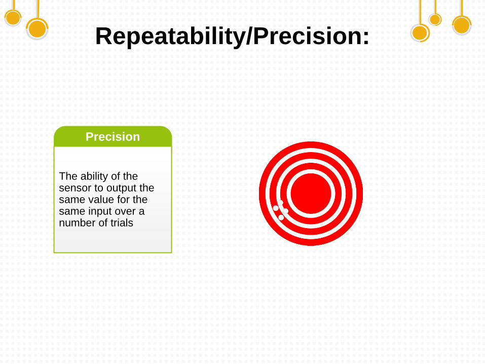
Repeatability/Precision:
The ability of the sensor to output the same value for the same input over a number of trials
Precision
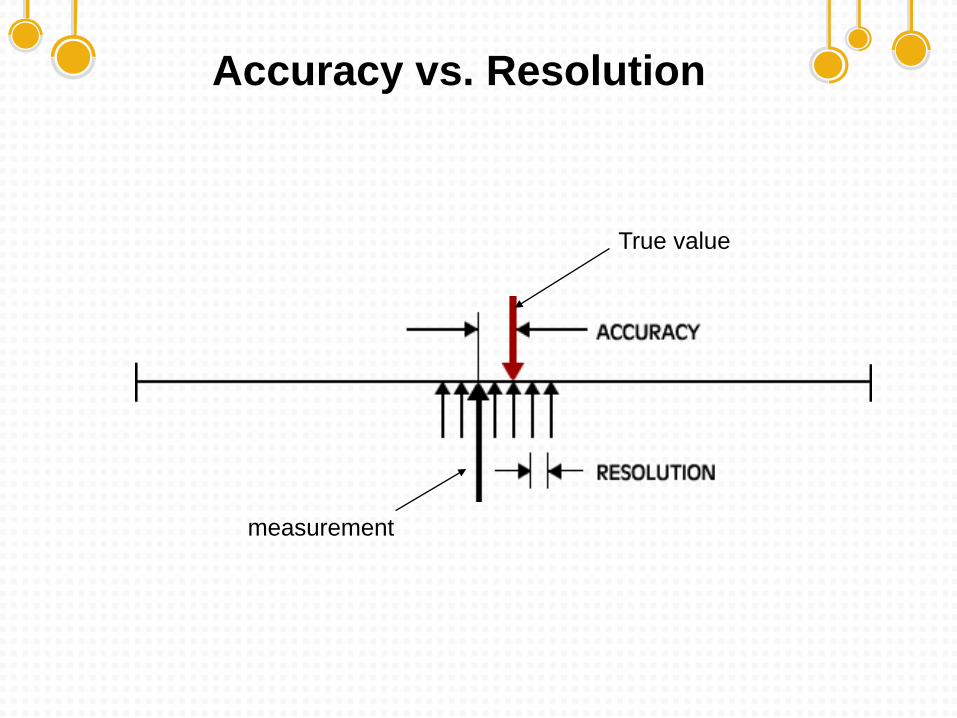
Accuracy vs. Resolution
True value
measurement
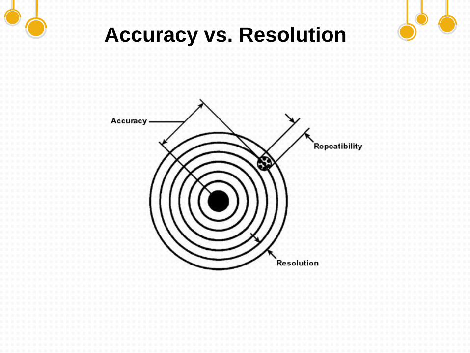
Accuracy vs. Resolution
Accuracy vs. Precision
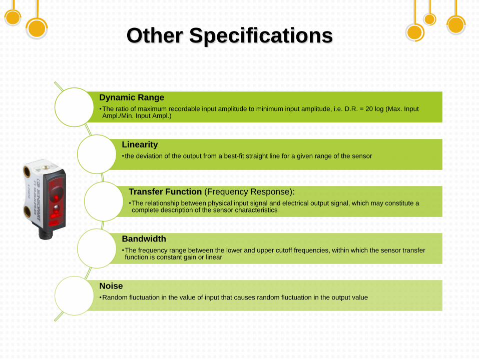
Other Specifications
Dynamic Range
•The ratio of maximum recordable input amplitude to minimum input amplitude, i.e. D.R. = 20 log (Max. Input Ampl./Min. Input Ampl.)
Linearity
• the deviation of the output from a best-fit straight line for a given range of the sensor
Transfer Function (Frequency Response):
•The relationship between physical input signal and electrical output signal, which may constitute a complete description of the sensor characteristics
Bandwidth
•The frequency range between the lower and upper cutoff frequencies, within which the sensor transfer function is constant gain or linear
Noise
•Random fluctuation in the value of input that causes random fluctuation in the output value
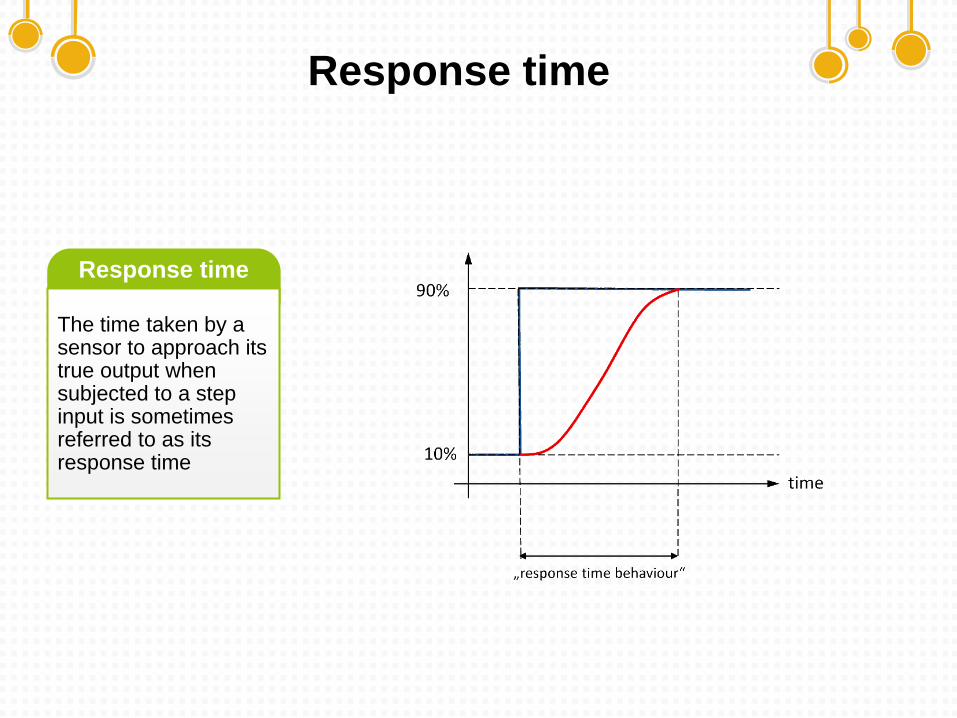
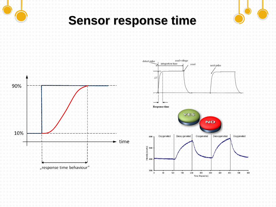
Response time
The time taken by a sensor to approach its true output when subjected to a step input is sometimes referred to as its response time
Response time
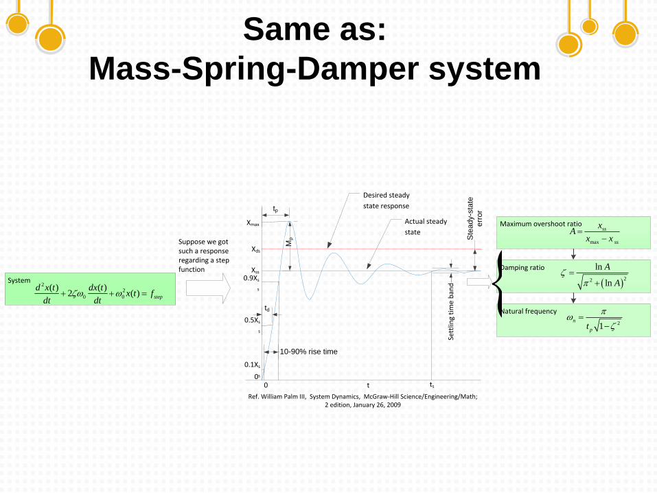
Same as:
Mass-Spring-Damper system
Sett
ling
tim
e b
and
tp
Mp
Xss
0.9Xs
s
0.5Xs
s
td
0.1Xs
s
10-90% rise time
Xmax
Ste
ad
y-s
tate
err
or
Desired steady
state response
Xds
t ts00
System2
2
0 0
( ) ( )2 ( ) step
d x t dx tx t f
dt dt
Actual steady
stateMaximum overshoot ratio
Suppose we got such a response regarding a step function
Ref. William Palm III, System Dynamics, McGraw-Hill Science/Engineering/Math; 2 edition, January 26, 2009
max
ss
ss
xA
x x
Damping ratio
22
ln
ln
A
A
Natural frequency
21n
pt
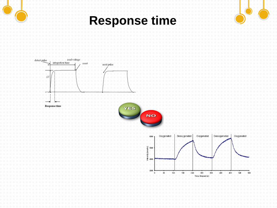
Response time
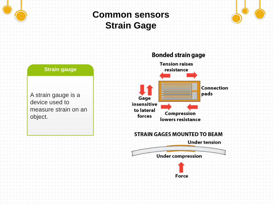
Common sensors
Strain Gage
A strain gauge is a
device used to
measure strain on an
object.
Strain gauge
Common sensors
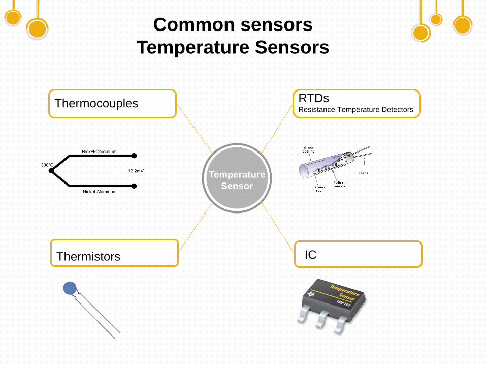
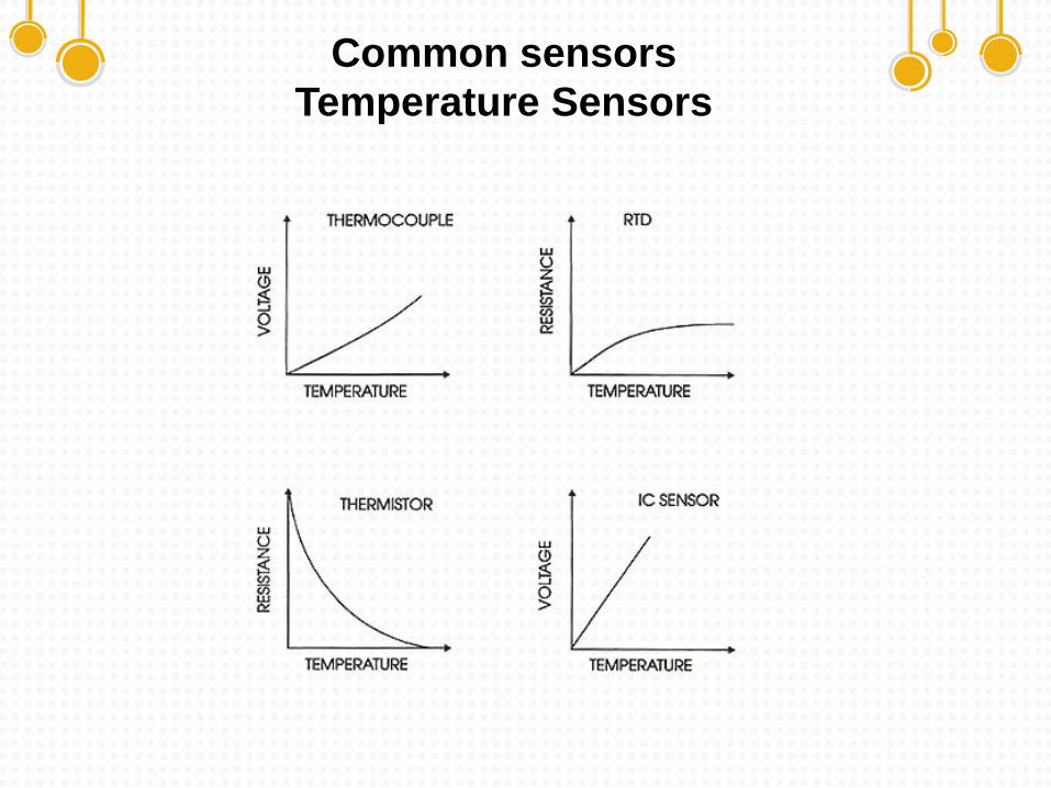
Temperature Sensors
Temperature
Sensor
IC
RTDsResistance Temperature Detectors
Thermocouples
Thermistors
Common sensors
Temperature Sensors
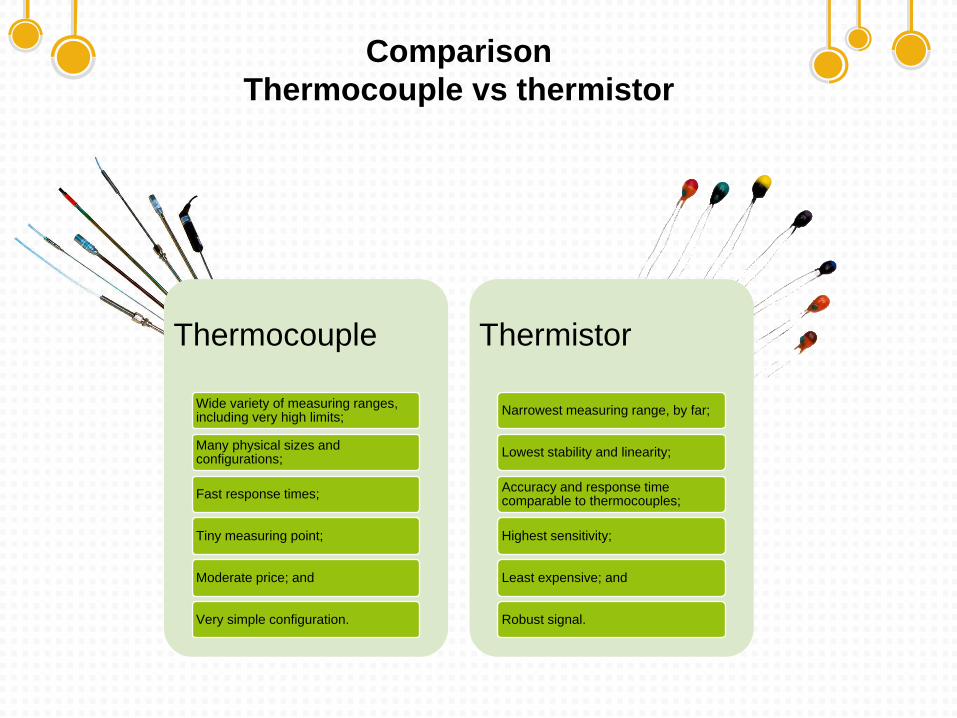
Comparison
Thermocouple vs thermistor
Thermocouple
Wide variety of measuring ranges, including very high limits;
Many physical sizes and configurations;
Fast response times;
Tiny measuring point;
Moderate price; and
Very simple configuration.
Thermistor
Narrowest measuring range, by far;
Lowest stability and linearity;
Accuracy and response time comparable to thermocouples;
Highest sensitivity;
Least expensive; and
Robust signal.
Pressure sensor
Comparison: Resistive vs capacitive screen
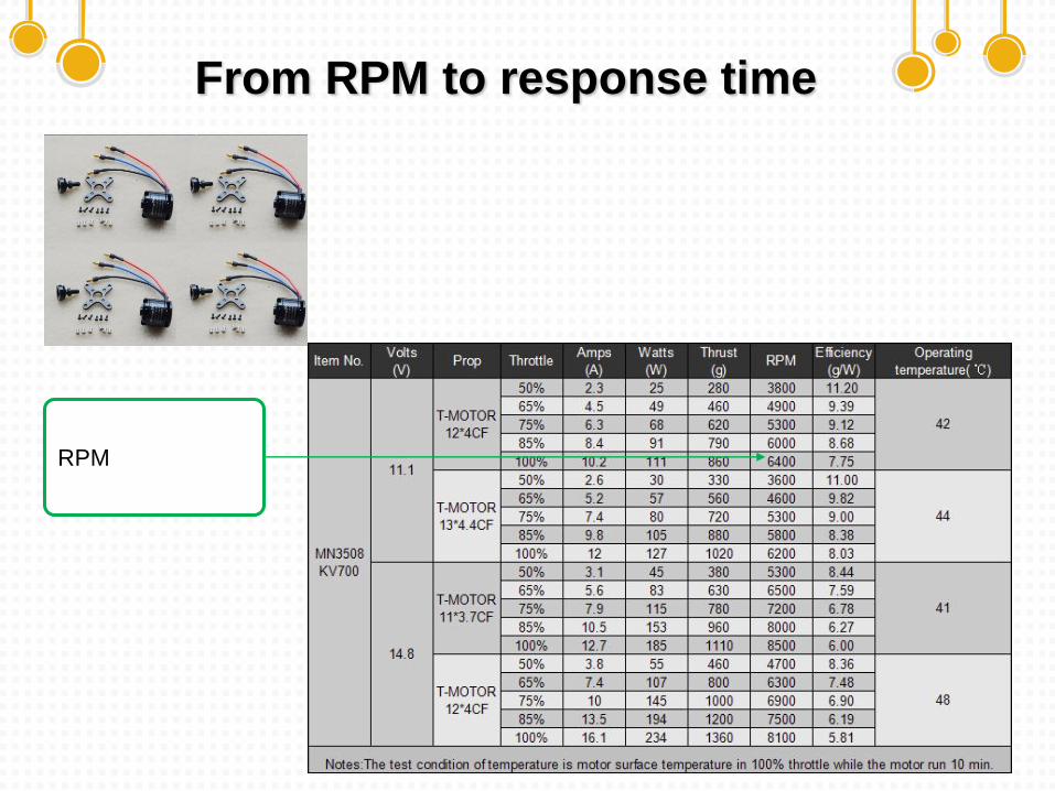
From RPM to response time
RPM
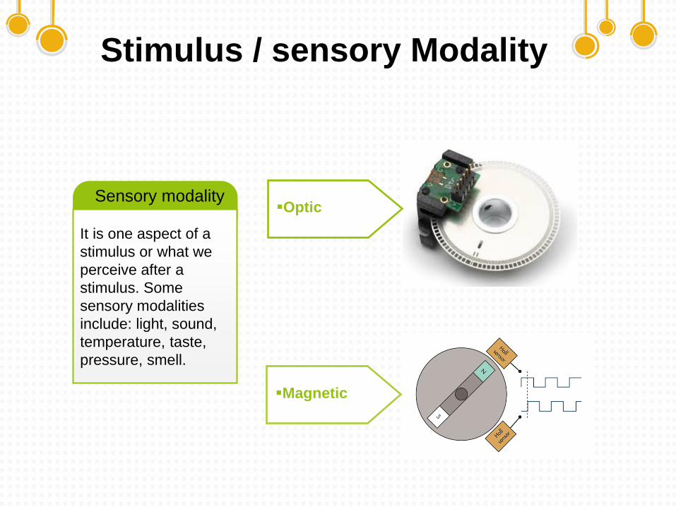
Stimulus / sensory Modality
It is one aspect of a
stimulus or what we
perceive after a
stimulus. Some
sensory modalities
include: light, sound,
temperature, taste,
pressure, smell.
Sensory modalityOptic
Magnetic
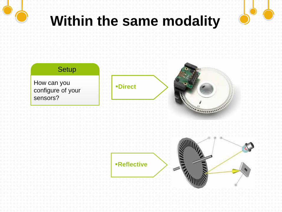
Within the same modality
How can you
configure of your
sensors?
Setup
Direct
Reflective
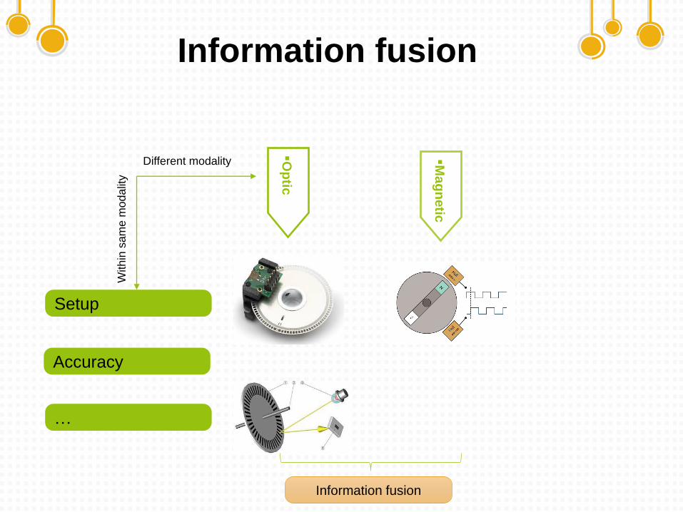
Information fusion
Op
tic
Mag
netic
Setup
Accuracy
…
Within
sam
e m
odalit
y
Information fusion
Different modality
Sensor response time
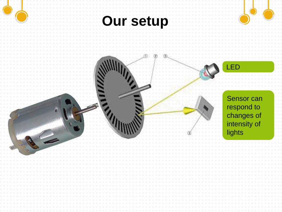
Our setup
LED
Sensor can
respond to
changes of
intensity of
lights
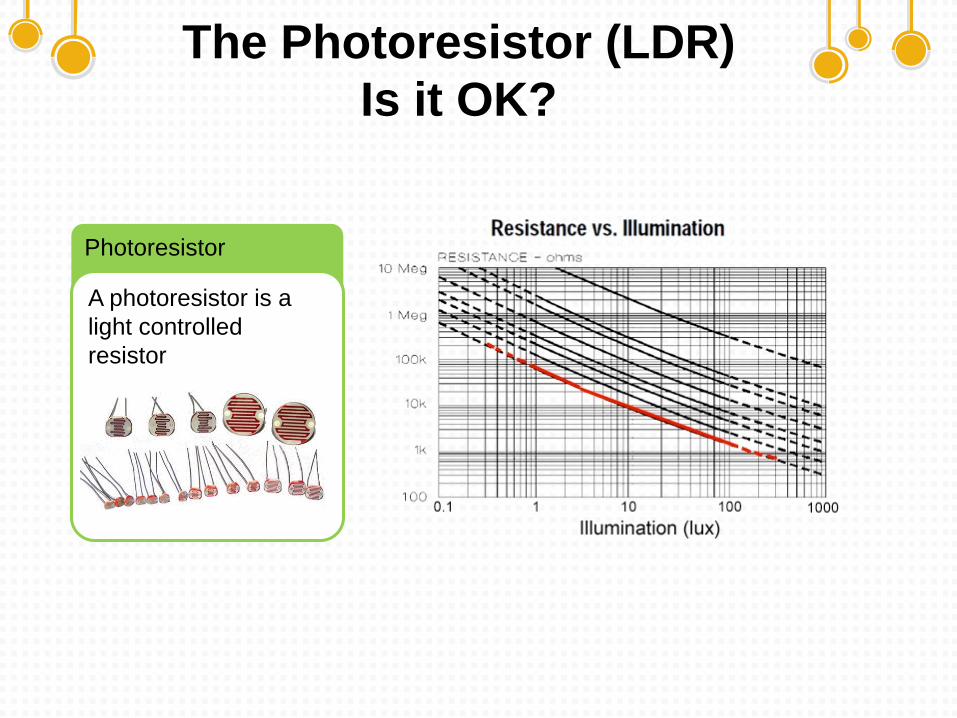
The Photoresistor (LDR)
Is it OK?
Photoresistor
A photoresistor is a
light controlled
resistor
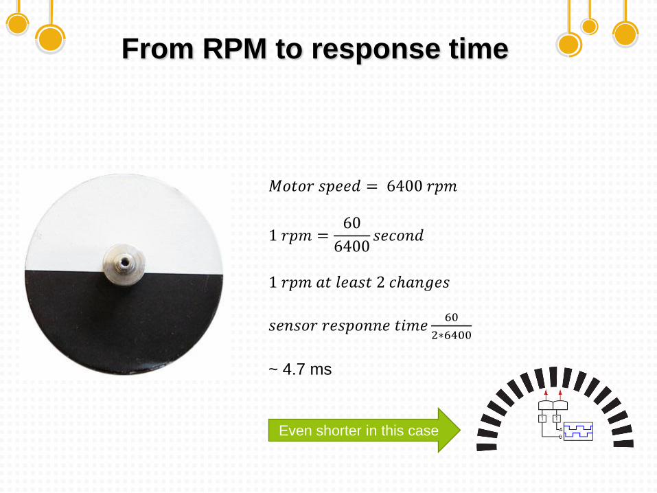
From RPM to response time
𝑀𝑜𝑡𝑜𝑟 𝑠𝑝𝑒𝑒𝑑 = 6400 𝑟𝑝𝑚
1 𝑟𝑝𝑚 =60
6400𝑠𝑒𝑐𝑜𝑛𝑑
1 𝑟𝑝𝑚 𝑎𝑡 𝑙𝑒𝑎𝑠𝑡 2 𝑐ℎ𝑎𝑛𝑔𝑒𝑠
𝑠𝑒𝑛𝑠𝑜𝑟 𝑟𝑒𝑠𝑝𝑜𝑛𝑛𝑒 𝑡𝑖𝑚𝑒60
2∗6400
~ 4.7 ms
Even shorter in this case
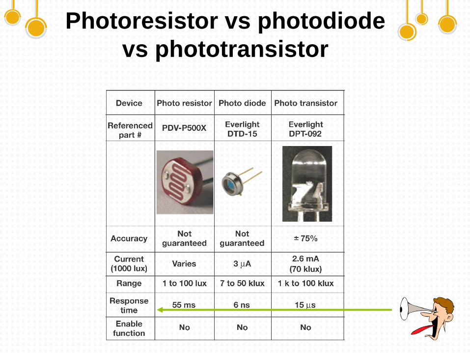
Photoresistor vs photodiode
vs phototransistor
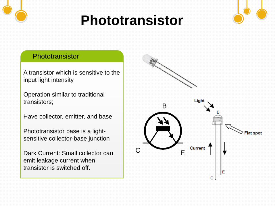
Phototransistor
A transistor which is sensitive to the
input light intensity
Operation similar to traditional
transistors;
Have collector, emitter, and base
Phototransistor base is a light-
sensitive collector-base junction
Dark Current: Small collector can
emit leakage current when
transistor is switched off.
Phototransistor
B
EC
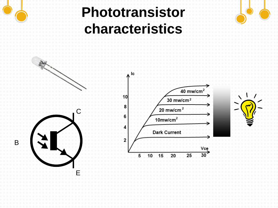
Phototransistor
characteristics
B
E
C
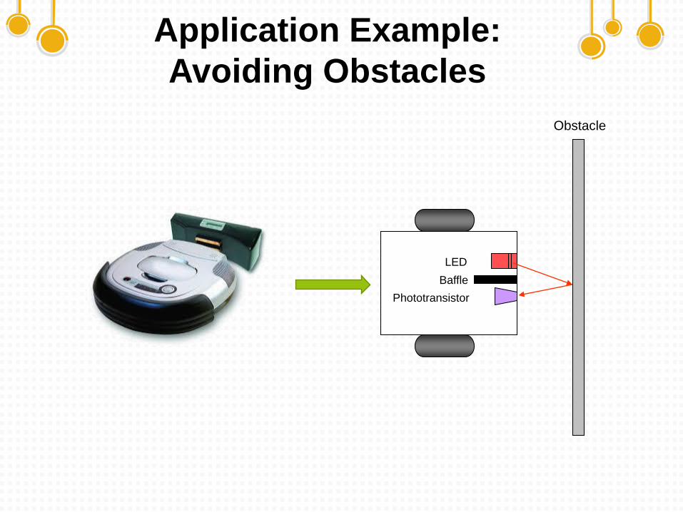
Obstacle
Application Example:
Avoiding Obstacles
LED
Baffle
Phototransistor
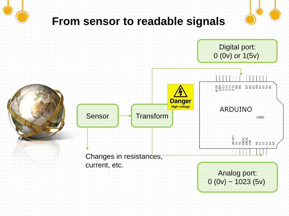
From sensor to readable signals
Sensor
Changes in resistances,
current, etc.
Transform
Digital port:
0 (0v) or 1(5v)
Analog port:
0 (0v) ~ 1023 (5v)
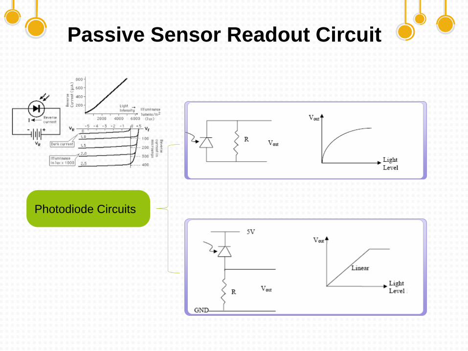
Passive Sensor Readout Circuit
Photodiode Circuits
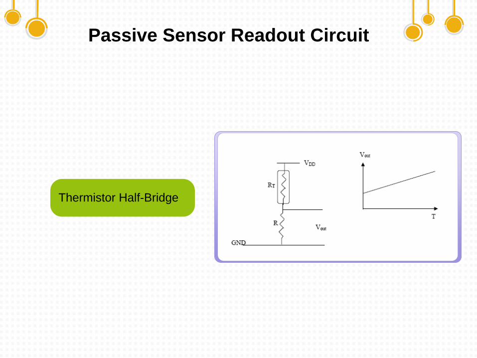
Passive Sensor Readout Circuit
Thermistor Half-Bridge
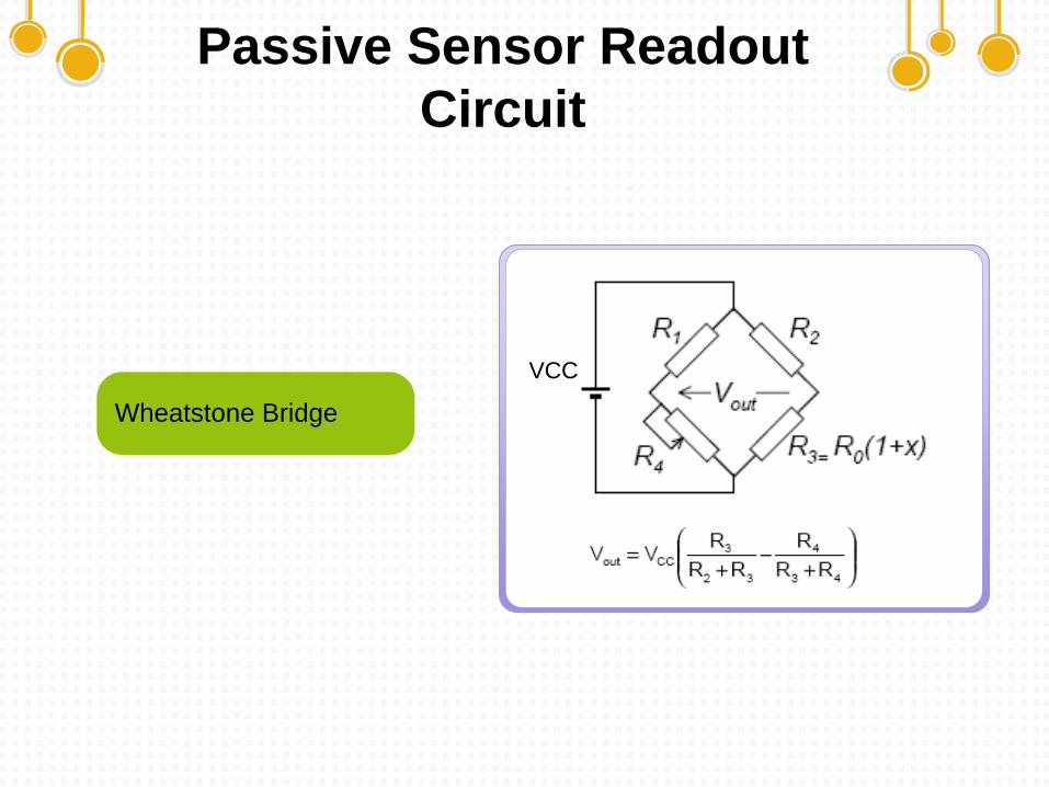
Passive Sensor Readout
Circuit
VCC
Wheatstone Bridge
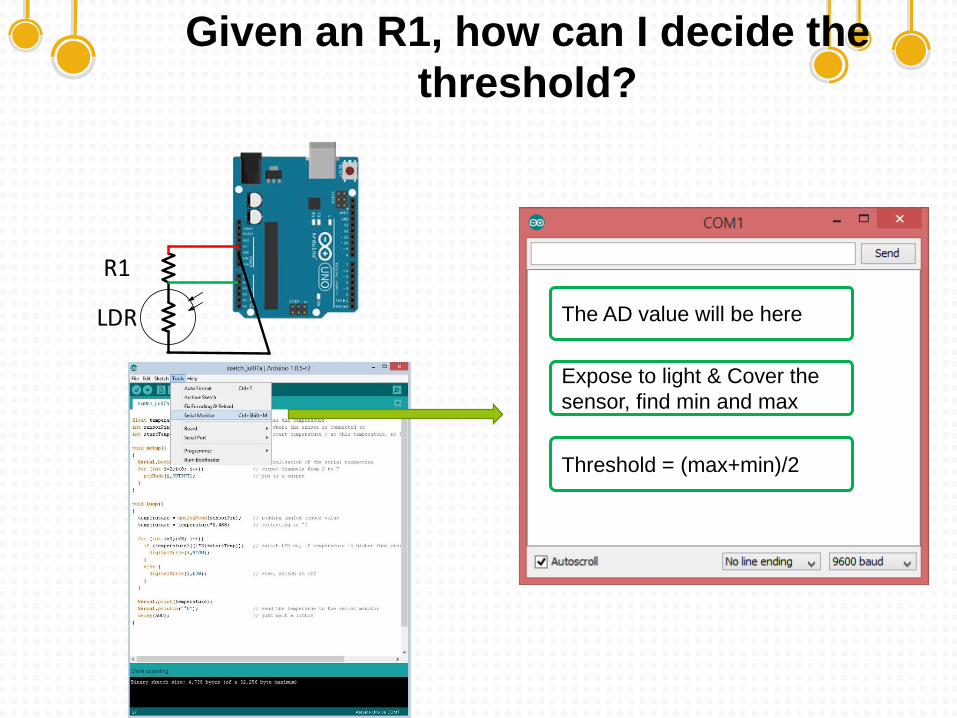
Given an R1, how can I decide the
threshold?
Digital out
LDR
R1
The AD value will be here
Expose to light & Cover the
sensor, find min and max
Threshold = (max+min)/2
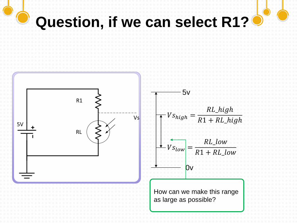
Question, if we can select R1?
5V
R1
RL
Vs
𝑉𝑠𝑙𝑜𝑤 =𝑅𝐿_𝑙𝑜𝑤
𝑅1 + 𝑅𝐿_𝑙𝑜𝑤
𝑉𝑠ℎ𝑖𝑔ℎ =𝑅𝐿_ℎ𝑖𝑔ℎ
𝑅1 + 𝑅𝐿_ℎ𝑖𝑔ℎ
0v
5v
How can we make this range
as large as possible?
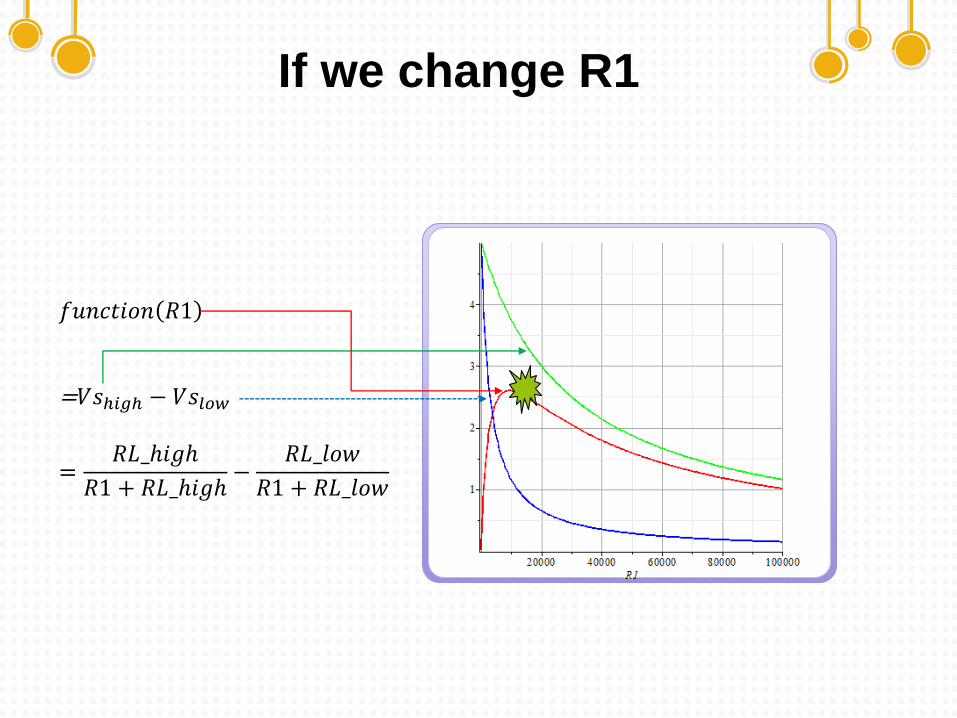
If we change R1
1
𝑓𝑢𝑛𝑐𝑡𝑖𝑜𝑛 𝑅1
=𝑉𝑠ℎ𝑖𝑔ℎ − 𝑉𝑠𝑙𝑜𝑤
=𝑅𝐿_ℎ𝑖𝑔ℎ
𝑅1 + 𝑅𝐿_ℎ𝑖𝑔ℎ−
𝑅𝐿_𝑙𝑜𝑤
𝑅1 + 𝑅𝐿_𝑙𝑜𝑤
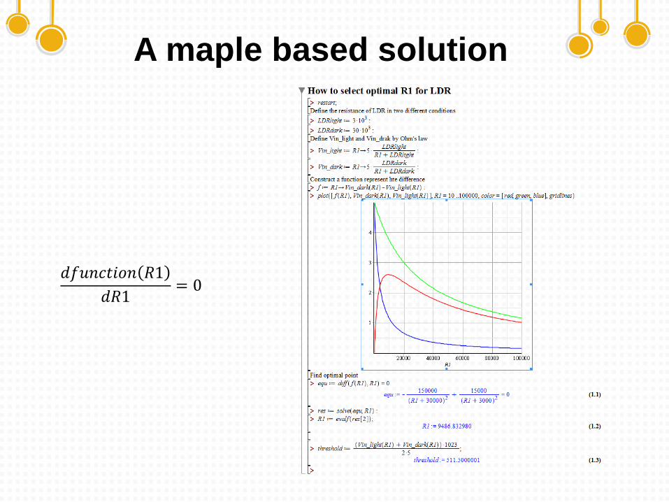
A maple based solution
1
𝑑𝑓𝑢𝑛𝑐𝑡𝑖𝑜𝑛 𝑅1
𝑑𝑅1= 0
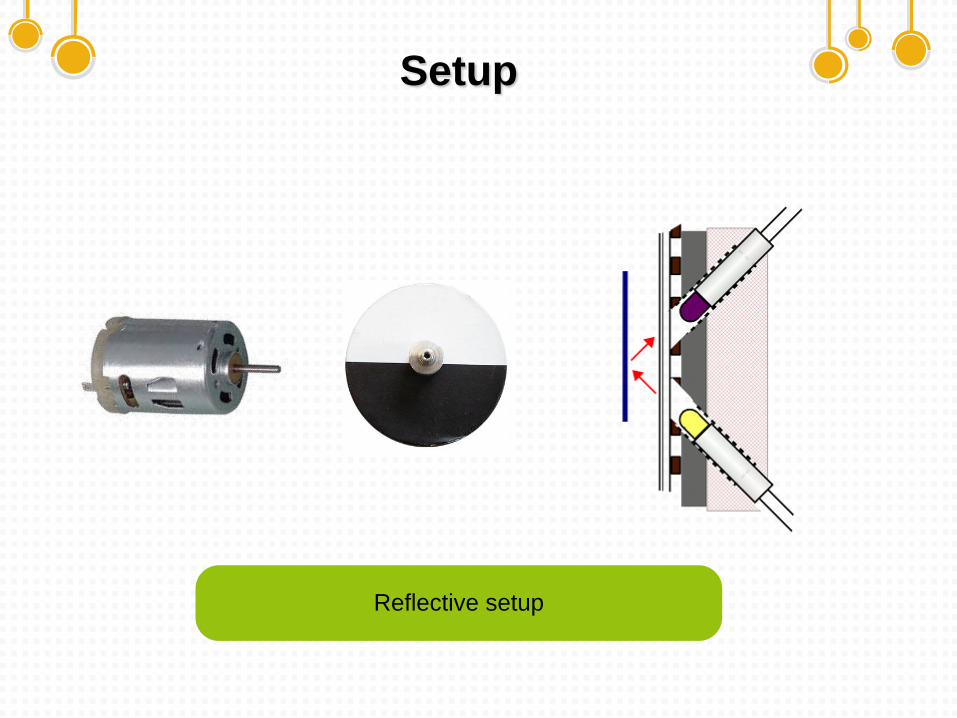
Setup
Reflective setup
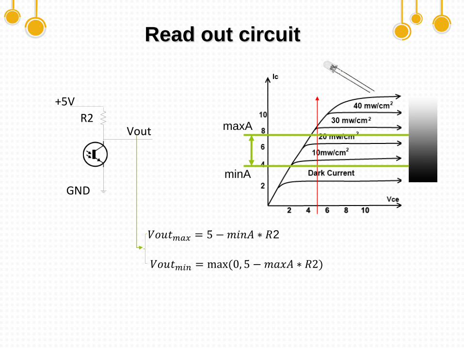
Read out circuit
R2
+5V
GND
Vout
𝑉𝑜𝑢𝑡𝑚𝑎𝑥 = 5 −𝑚𝑖𝑛𝐴 ∗ 𝑅2
maxA
minA
𝑉𝑜𝑢𝑡𝑚𝑖𝑛 = max(0, 5 − 𝑚𝑎𝑥𝐴 ∗ 𝑅2)
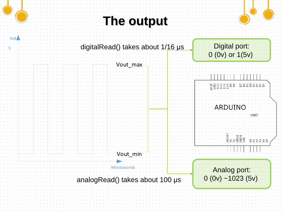
The output
Microseconds
Volt
Vout_min
Vout_max
5 Digital port:
0 (0v) or 1(5v)
Analog port:
0 (0v) ~1023 (5v) analogRead() takes about 100 μs
digitalRead() takes about 1/16 μs
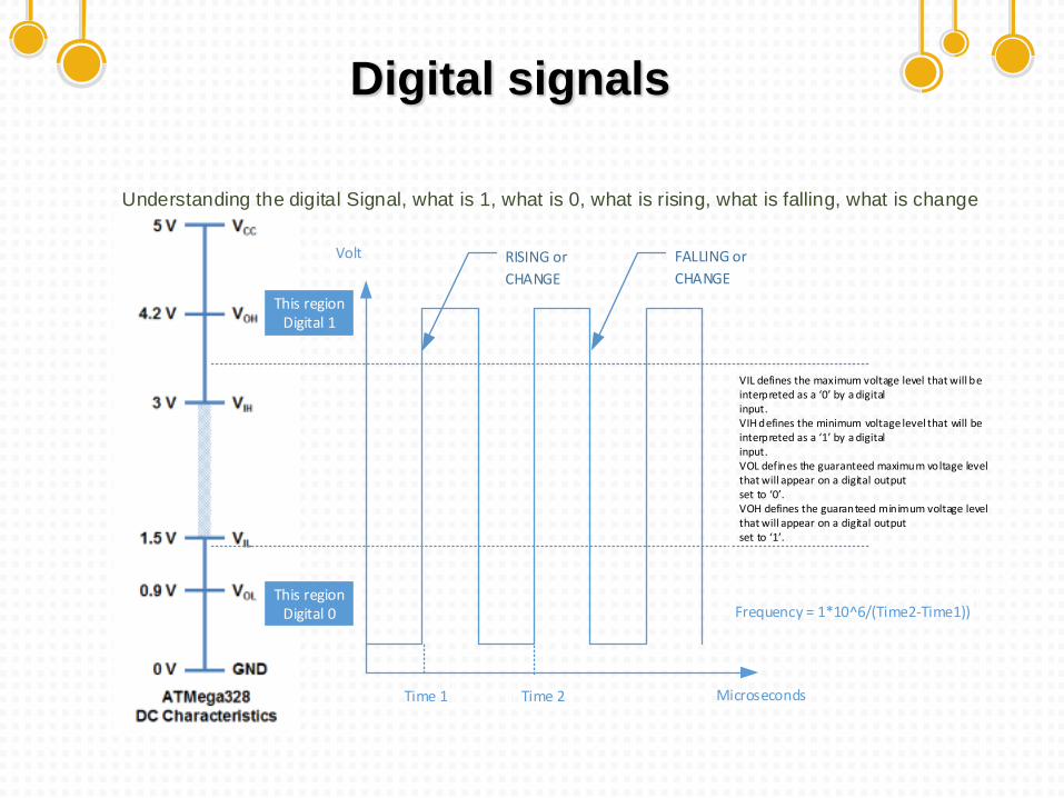
Digital signals
Understanding the digital Signal, what is 1, what is 0, what is rising, what is falling, what is change
VIL defines the maximum voltage level that will be interpreted as a 0 by a digital input. VIH defines the minimum voltage level that will be interpreted as a 1 by a digital input. VOL defines the guaranteed maximum voltage level that will appear on a digital output set to 0 . VOH defines the guaranteed minimum voltage level that will appear on a digital output set to 1 .
FALLING or
CHANGE
RISING or
CHANGE
Time 1 Time 2
Frequency = 1*10^6/(Time2-Time1))
Microseconds
Volt
This regionDigital 1
This regionDigital 0
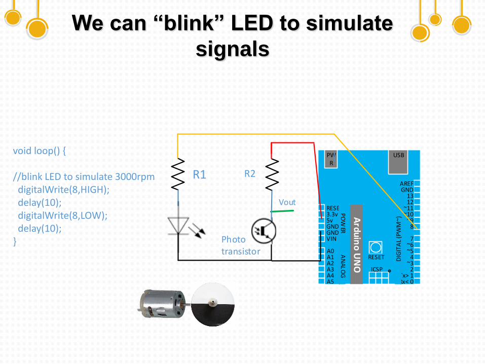
We can “blink” LED to simulate
signals
USBPWR
RESET3.3v5vGNDGNDVIN
A0A1A2A3A4A5
AREFGND
1312
~11~10
~98
7~6~5
4~3
2Tx> 1Rx< 0
PO
WER
AN
AL
OG
DIG
ITA
L (P
WM
~)
RESET
Ard
uin
o U
NO
ICSP
Photo transistor
R2R1
Vout
void loop() {
//blink LED to simulate 3000rpmdigitalWrite(8,HIGH);delay(10);digitalWrite(8,LOW);delay(10);
}
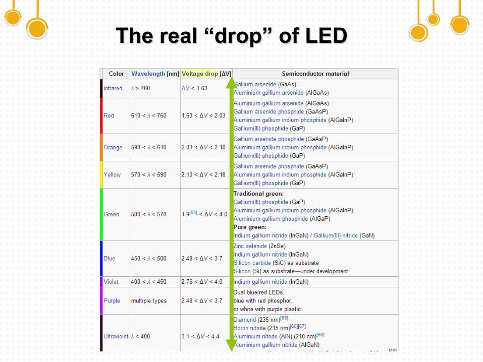
The real “drop” of LED
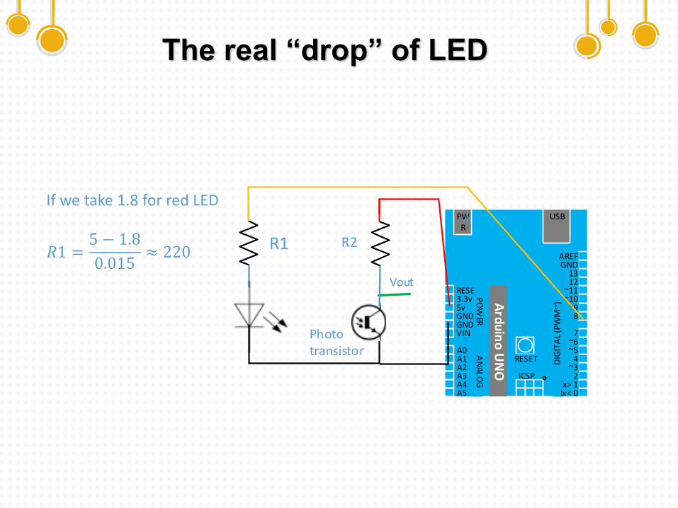
The real “drop” of LED
If we take 1.8 for red LED
𝑅1 =5 − 1.8
0.015≈ 220
USBPWR
RESET3.3v5vGNDGNDVIN
A0A1A2A3A4A5
AREFGND
1312
~11~10
~98
7~6~5
4~3
2Tx> 1Rx< 0
PO
WER
AN
AL
OG
DIG
ITA
L (P
WM
~)
RESET
Ard
uin
o U
NO
ICSP
Photo transistor
R2R1
Vout
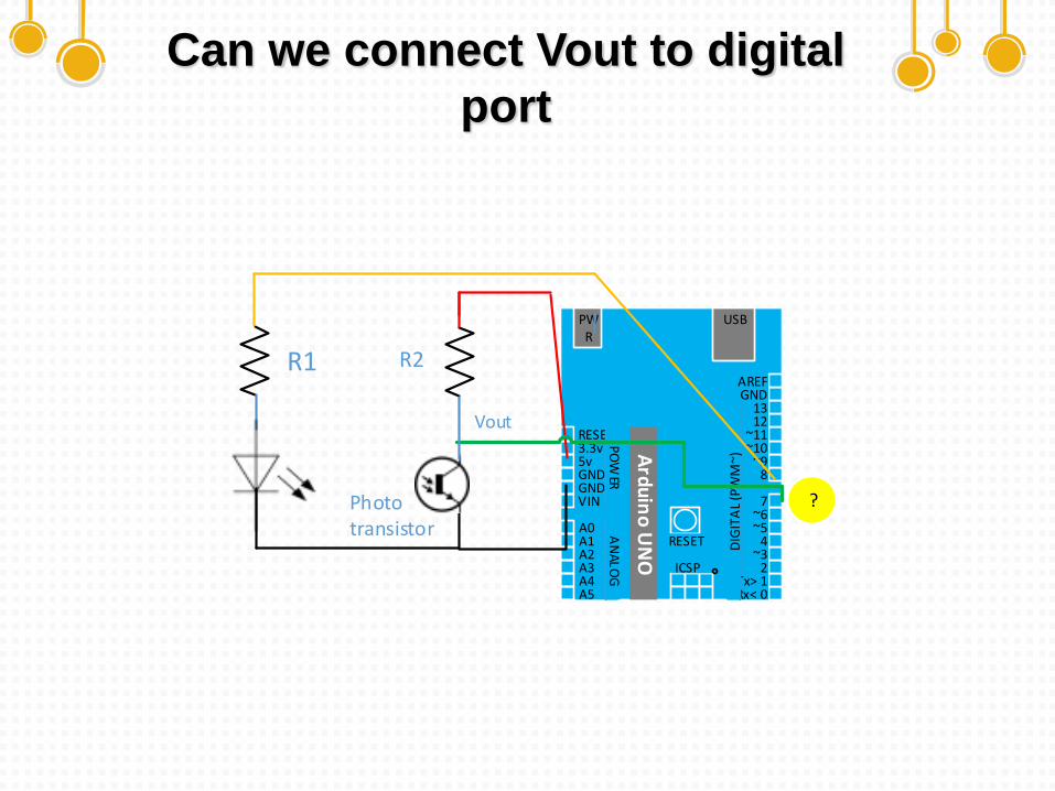
Can we connect Vout to digital
port
USBPWR
RESET3.3v5vGNDGNDVIN
A0A1A2A3A4A5
AREFGND
1312
~11~10
~98
7~6~5
4~3
2Tx> 1Rx< 0
PO
WER
AN
AL
OG
DIG
ITA
L (P
WM
~)
RESET
Ard
uin
o U
NO
ICSP
Photo transistor
R2R1
Vout
?
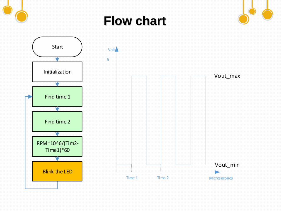
Flow chart
Start
Initialization
Find time 1
RPM=10^6/(Tim2-Time1)*60
Find time 2
Blink the LEDMicroseconds
Volt
Vout_min
Vout_max
5
Time 1 Time 2
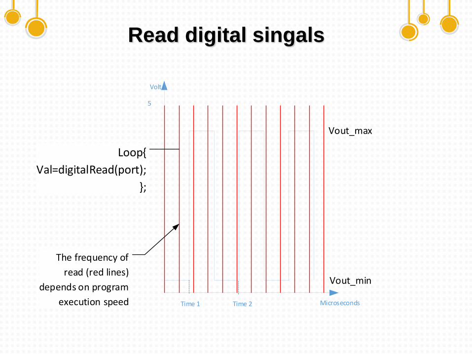
Read digital singals
Microseconds
Volt
Vout_min
Vout_max
5
Loop{
Val=digitalRead(port);
};
Time 1 Time 2
The frequency of
read (red lines)
depends on program
execution speed
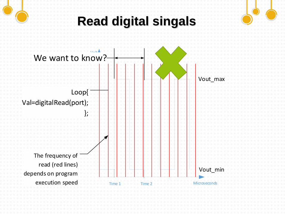
Read digital singals
Microseconds
Volt
Vout_min
Vout_max
5
Loop{
Val=digitalRead(port);
};
We want to know?
Time 1 Time 2
The frequency of
read (red lines)
depends on program
execution speed
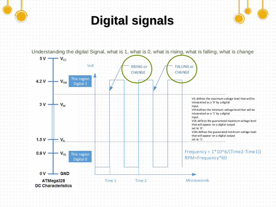
Digital signals
Understanding the digital Signal, what is 1, what is 0, what is rising, what is falling, what is change
VIL defines the maximum voltage level that will be interpreted as a 0 by a digital input. VIH defines the minimum voltage level that will be interpreted as a 1 by a digital input. VOL defines the guaranteed maximum voltage level that will appear on a digital output set to 0 . VOH defines the guaranteed minimum voltage level that will appear on a digital output set to 1 .
FALLING or
CHANGE
RISING or
CHANGE
Time 1 Time 2
Frequency = 1*10^6/(Time2-Time1))RPM=Frequency*60
Microseconds
Volt
This regionDigital 1
This regionDigital 0
Interrupts
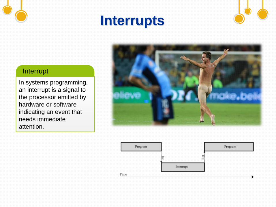
In systems programming,
an interrupt is a signal to
the processor emitted by
hardware or software
indicating an event that
needs immediate
attention.
Interrupt
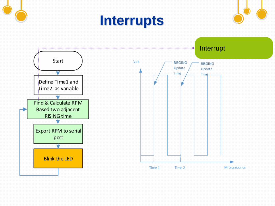
Interrupts
Start
Define Time1 and Time2 as variable
Find & Calculate RPMBased two adjacent
RISING time
Export RPM to serial port
Blink the LED
Interrupt
RISGING
Update
Time
RISGING
Update
Time
Time 1 Time 2 Microseconds
Volt
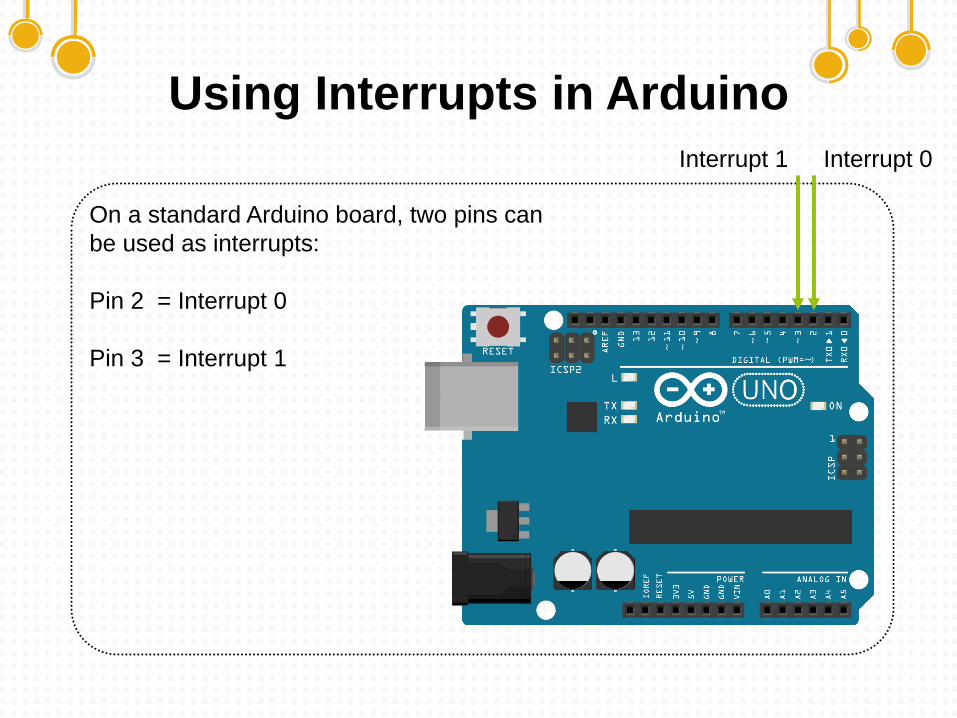
Using Interrupts in Arduino
On a standard Arduino board, two pins can
be used as interrupts:
Pin 2 = Interrupt 0
Pin 3 = Interrupt 1
Interrupt 1 Interrupt 0
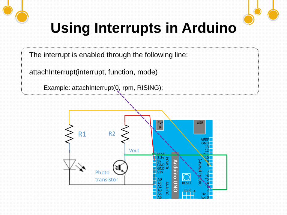
Using Interrupts in Arduino
The interrupt is enabled through the following line:
attachInterrupt(interrupt, function, mode)
Example: attachInterrupt(0, rpm, RISING);
USBPWR
RESET3.3v5vGNDGNDVIN
A0A1A2A3A4A5
AREFGND
1312
~11~10
~98
7~6~5
4~3
2Tx> 1Rx< 0
PO
WER
AN
AL
OG
DIG
ITA
L (P
WM
~)
RESET
Ard
uin
o U
NO
ICSP
Photo transistor
R2R1
Vout
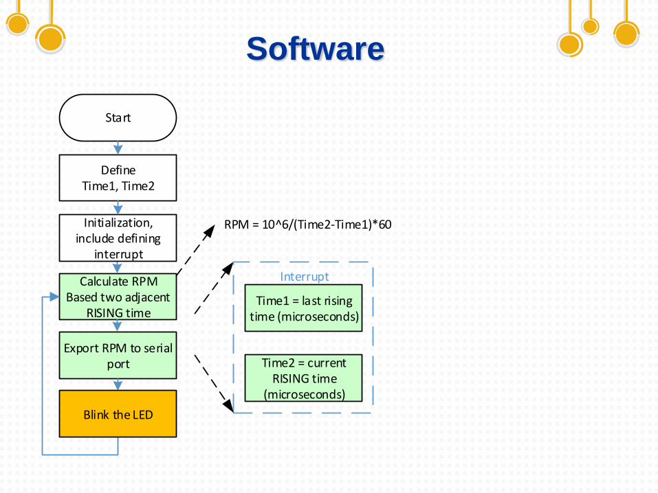
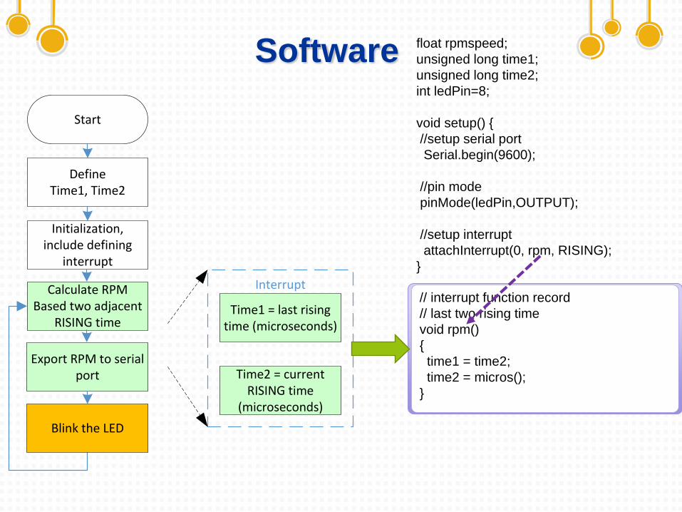
Software
Start
Define Time1, Time2
Calculate RPMBased two adjacent
RISING time
Export RPM to serial port
Time1 = last rising time (microseconds)
Time2 = current RISING time
(microseconds)
Interrupt
Initialization, include defining
interrupt
RPM = 10^6/(Time2-Time1)*60
Blink the LED
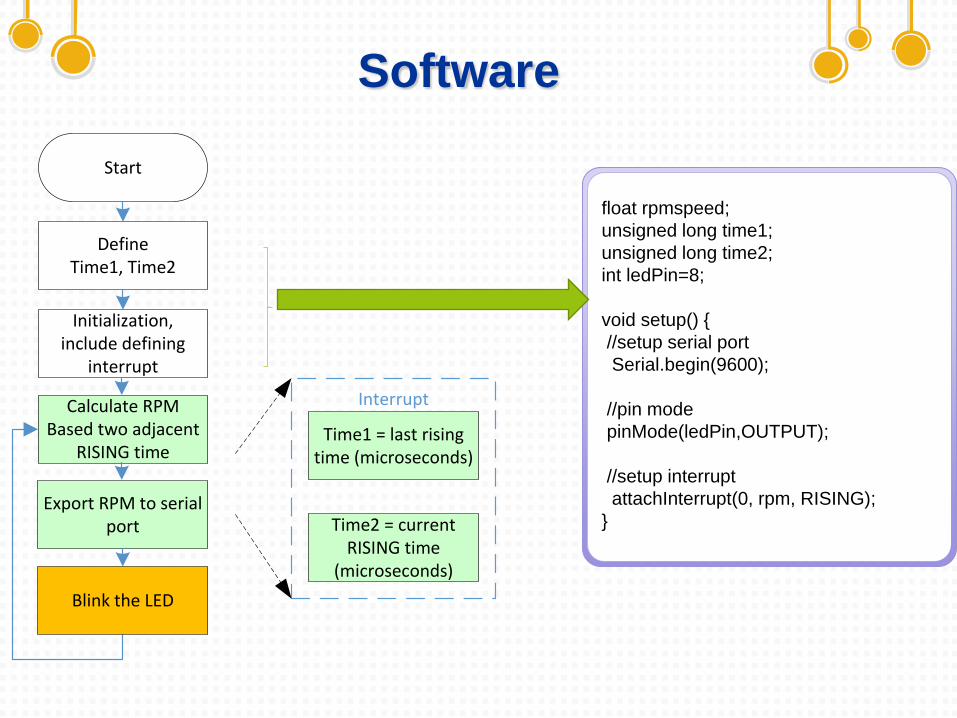
Software
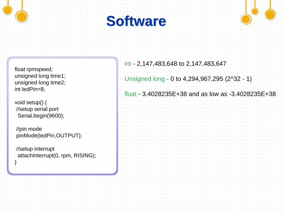
float rpmspeed;
unsigned long time1;
unsigned long time2;
int ledPin=8;
void setup() {
//setup serial port
Serial.begin(9600);
//pin mode
pinMode(ledPin,OUTPUT);
//setup interrupt
attachInterrupt(0, rpm, RISING);
}
Start
Define Time1, Time2
Calculate RPMBased two adjacent
RISING time
Export RPM to serial port
Time1 = last rising time (microseconds)
Time2 = current RISING time
(microseconds)
Interrupt
Initialization, include defining
interrupt
Blink the LED
Software
float rpmspeed;
unsigned long time1;
unsigned long time2;
int ledPin=8;
void setup() {
//setup serial port
Serial.begin(9600);
//pin mode
pinMode(ledPin,OUTPUT);
//setup interrupt
attachInterrupt(0, rpm, RISING);
}
int - 2,147,483,648 to 2,147,483,647
Unsigned long - 0 to 4,294,967,295 (2^32 - 1)
float - 3.4028235E+38 and as low as -3.4028235E+38
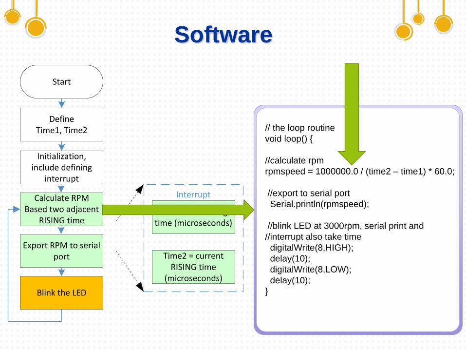
Start
Define Time1, Time2
Calculate RPMBased two adjacent
RISING time
Export RPM to serial port
Time1 = last rising time (microseconds)
Time2 = current RISING time
(microseconds)
Interrupt
Initialization, include defining
interrupt
Blink the LED
Software
// the loop routine
void loop() {
//calculate rpm
rpmspeed = 1000000.0 / (time2 – time1) * 60.0;
//export to serial port
Serial.println(rpmspeed);
//blink LED at 3000rpm, serial print and
//interrupt also take time
digitalWrite(8,HIGH);
delay(10);
digitalWrite(8,LOW);
delay(10);
}
Software
Start
Define Time1, Time2
Calculate RPMBased two adjacent
RISING time
Export RPM to serial port
Time1 = last rising time (microseconds)
Time2 = current RISING time
(microseconds)
Interrupt
Initialization, include defining
interrupt
Blink the LED
// interrupt function record
// last two rising time
void rpm()
{
time1 = time2;
time2 = micros();
}
float rpmspeed;
unsigned long time1;
unsigned long time2;
int ledPin=8;
void setup() {
//setup serial port
Serial.begin(9600);
//pin mode
pinMode(ledPin,OUTPUT);
//setup interrupt
attachInterrupt(0, rpm, RISING);
}
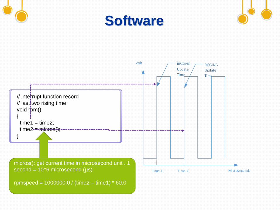
Software
micros(): get current time in microsecond unit . 1
second = 10^6 microsecond (µs)
rpmspeed = 1000000.0 / (time2 – time1) * 60.0
// interrupt function record
// last two rising time
void rpm()
{
time1 = time2;
time2 = micros();
}
RISGING
Update
Time
RISGING
Update
Time
Time 1 Time 2 Microseconds
Volt

Prototype
phototrasistor
123d.circuits.io

Workshops
03
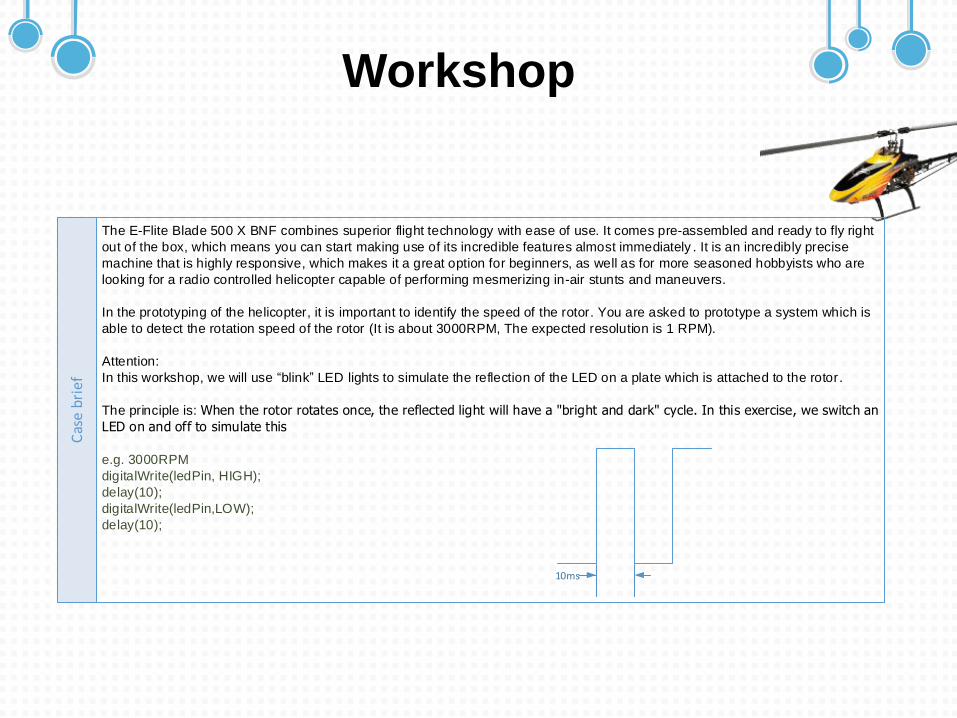
Workshop
The E-Flite Blade 500 X BNF combines superior flight technology with ease of use. It comes pre-assembled and ready to fly right
out of the box, which means you can start making use of its incredible features almost immediately . It is an incredibly precise
machine that is highly responsive, which makes it a great option for beginners, as well as for more seasoned hobbyists who are
looking for a radio controlled helicopter capable of performing mesmerizing in-air stunts and maneuvers.
In the prototyping of the helicopter, it is important to identify the speed of the rotor. You are asked to prototype a system which is
able to detect the rotation speed of the rotor (It is about 3000RPM, The expected resolution is 1 RPM).
Attention:
In this workshop, we will use blink LED lights to simulate the reflection of the LED on a plate which is attached to the rotor.
The principle is: When the rotor rotates once, the reflected light will have a "bright and dark" cycle. In this exercise, we switch an
LED on and off to simulate this
e.g. 3000RPM
digitalWrite(ledPin, HIGH);
delay(10);
digitalWrite(ledPin,LOW);
delay(10);
Cas
e b
rie
f
10ms
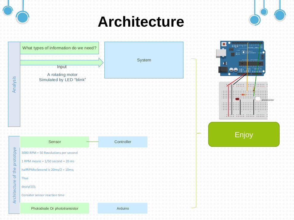
ArchitectureA
nal
ysis
System
What types of information do we need?
A rotating motor
Simulated by LED blink
Arc
hit
ect
ure
of
the
pro
totp
ye
Sensor Controller
Photodiode Or phototransistor Arduino
3000 RPM = 50 Revolutions per second
1 RPM means = 1/50 second = 20 ms
halfRPMtoSecond is 20ms/2 = 10ms;
Thus
dealy(10);
Consider sensor reaction time
Enjoy
phototrasistor

Summary
04
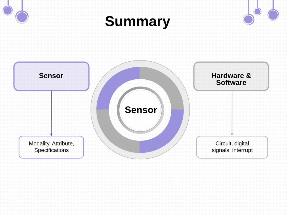
Summary
Circuit, digital
signals, interrupt
Hardware & Software
Modality, Attribute,
Specifications
Sensor
Sensor
Thank you
Product Dynamics, L-E-2, Sensors
Io2022
Prof. Dr. Ir. J.M.P Geraedts
Dr. Y. Song, Martin Verwaal, Adrie Kooijman, Ir. Sander Minnoye
Faculty of Industrial Design Engineering
Delft University of Technology

PPT模板下载:www.1ppt.com/moban/ 行业PPT模板:www.1ppt.com/hangye/
节日PPT模板:www.1ppt.com/jieri/ PPT素材下载:www.1ppt.com/sucai/PPT背景图片:www.1ppt.com/beijing/ PPT图表下载:www.1ppt.com/tubiao/ 优秀PPT下载:www.1ppt.com/xiazai/ PPT教程: www.1ppt.com/powerpoint/
Word教程: www.1ppt.com/word/ Excel教程:www.1ppt.com/excel/ 资料下载:www.1ppt.com/ziliao/ PPT课件下载:www.1ppt.com/kejian/ 范文下载:www.1ppt.com/fanwen/ 试卷下载:www.1ppt.com/shiti/
教案下载:www.1ppt.com/jiaoan/