Embed Size (px)
Citation preview

NATIONAL RADIO ASTRONOMY OBSERVATORYCharlottesville, Virginia
Electronics Division Technical Note No. 155
Title: PROGRAM s SCAY.Thit* FOR THE ANALYSIS OF DIFLECTRIC MATCHING LAYERS
Author(s): Nancyjane Bailey and A. R. Kerr
Date: September 18, 1989
DISTRIBUTION:
GB CVGB Library ER LibraryR. Lacasse IR LibraryR. Weimer M. BalisterD. Schiebel C. BurgessE. Childers S-K PanC. Brockway A. R. KerrJ. Coe N. BaileyR. Norrod S. SrikanthS. White L. D'AddarioG. Behrens N. HornerR. FisherF. CrewsB. Peery
TU VLALibrary Downtown VLA LibraryLibrary Mountain P. NapierJ. Payne J. CampbellR. Freund W. BrundageJ. Lamb P. LilleD. EmersonP. JewellJ. CochranA. Perfecto

PROGRAM *SCArita" FOR THE ANALYSIS OF DIELECTRIC MATCHING LAYERS
Nancyjane Bailey and A. R. Kerr
September 18, 1989
INTRODUCTION
Program SCATTER, written by Rachael Padman to calculate the co-polar andcross-polar reflection and transmission characteristics of grooved dielectricpanels, is now available on the NRAO Charlottesville Convex. The originalprogram is fully described in [1]. Two errors in the original programdescription have been corrected, as described in Appendix I.
The program is interactive, prompting the user for information about thecharacteristics of the dielectric slab, the frequencies of interest and theorientation of the incident wave. The results are output directly tostandard output, and a summary of the output data is also placed into anASCII file. This data file follows the conventions of a Lotus 123.PRN fileand may be imported directly into a Lotus worksheet.
DEFINITION OF THE PROBLEM
As shown in Figure 1, the x, y, and z directions are defined by theorientation of the incident wave to the dielectric slab. The xy plane is theplane of the surface of the dielectric, while the yz plane is the plane ofincidence, containing both the incident ray and the normal to the dielectricsurface. The angle of incidence, 9, is the angle the incident ray makes withthe normal to the dielectric surface. The optic axis lies in the plane ofthe dielectric surface and is perpendicular to the grooves. The angle 0 isthat between the normal to the plane of incidence and the direction of thegrooves. An incident wave is said to be TE if its E-field is perpendicularto the plane of incidence, and TM if its E-field lies in the plane ofincidence. The output reflection and transmission coefficients are given asco-polar and cross-polar TE and TM components.
The co- and cross-polar reflection coefficients for incident TE and TMwaves are complex quantities and are defined as follows:
R11 is the x-component of the reflected E-field when a pure TE wave, with— 1, is incident on the slab.
B.21 is the y-component of the reflected E-field when a pure TE wave, withE, — 1, is incident on the slab.R the x-component of the reflected E-field when a pure TM wave, withEy — 1, is incident on the slab.Rza is the y-component of the reflected E-field when a pure TM wave, withEy — 1, is incident on the slab.
The transmission coefficients are defined in an analogous way.

Fig. 1. Definition of axes and angles.
Fig. 2. Triangular and rectangular grooves.
2

PROGRAM "SCATTER" FOR. TRIANGULAR AND RECTANGULAR GROOVES
SCATTER was designed to be quite general, computing the reflection andtransmission coefficients of an anisotropic layer whose dielectric tensorvaries with z in an arbitrary manner. The version obtained from Padman was amodified version of the original SCATTER of (1], and was configured toanalyze a dielectric slab with triangular grooves (Figure 2(a)). SubroutineGROOVE defines the variation of the dielectric tensor with depth. By makinga change in the function PROFILE (called by subroutine GROOVEY, it waspossible to modify the program to analyze a slab with rectangular grooves(Figure 2(b)). Both versions are on the NRAO Charlottesville Convex.SCATTER12 is for triangular grooves and SCATTER13 is for rectangular grooves.SCATTER12 and SCATTER13 differ only in the definition of the functionPROFILE(z), whose value gives the ratio of the width of the tooth to thetooth spacing (pitch), as a function of distance z normal to the slab. Bothversions of the code are reasonably well documented; code originally writtenby Padman but incompatible with the Convex was simply commented out andremains in the source code.
Appendix I describes corrections to the original SCATTER report andFortran code [1].
EXAMPLES
Example 1 -- Verification of program SCATTER at normal incidence
To check operation of the program, it was used to analyze a thick slabof PTFE (Er — 2.1) with rectangular grooves designed to provide perfectmatching at 230 GHz to a normally incident wave with E-field perpendicular tothe grooves. This occurswhen the effective dielectric constant of thegrooved layer is SQRT(2.1) and the groove depth A0/SQRT(2.1). The toothwidth is chosen to give the desired effective dielectric constant using theseries capacitor analogy, which is valid provided the groove pitch << A0/2.Specifically the following parameter values were used:
Dielectric constant e — 2.1Angle between x-axis and grooves 0 —Angle of incidence 8 — 0Total slab thickness — 1.5 cmGroove depth — 0.0271 cmGroove pitch — 0.0065 cmTooth width — 0.0038 cmGrooves on two surfaces not crossed
Figure 3 shows the results for Ru and 1112 computed by SCATTER13. Asexpected, FIL22 becomes extremely small at 230 GHz. The interference betweenreflections from the two sides of the slab are seen as the fast ripplesuperimposed on the slower frequency response of the individual groovedlayers. Appendix 11 shows the dialogue with the program, and the resultsdisplayed on the monitor screen for this example.
3
Freq (C3-1•4CI R11 + R22
0.28
0.24
0.22
0.2
OAS
0.18
0.14
0.12
axe048
044
042
a 14 24201818 221210
Freq. (a4z)R11 (rrpag) R22 (mcg)
Fig. 3. Example 1: Test of program SCATTER using a PTFE window withparallel rectangular grooves on both faces. The grooves aredesigned to be perfectly matched for normal incidence at 230 GHzwhen the E-field is perpendicular to the grooves.
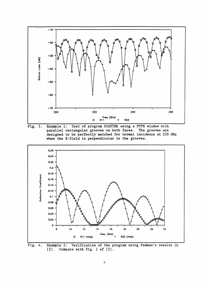
Fig. 4. Example 2: Verification of the program using Padman's results in[2]. Compare with Fig. 1 of [2].
4
Example 2 -- Verification of Padman's results in reference (2].
This example reproduces the results of Padman's IEEE-AP paper (21 usingSCATTER12. The results in Figure 4 are in close agreement with the publishedresults .
Example 3 - - A 230-GHz PTFE window with triangular grooves for use at normalincidence •
This window has parallel grooves on the two surfaces. The depth andpitch of the triangular grooves were chosen to give acceptably lowreflections for both polarizations -- a tool angle of 23° is used in thisexample:
Dielectric constant Er 2.1Angle between x-axis and grooves 0Angle of incidence 8 — 0Total slab thickness — 0.4666 cmGroove depth — 0.1066 cmGroove pitch — 0.0432 cmGrooves on two surfaces not crossed
The computed values of R11 and R22 for this window are shown in Figure 5.
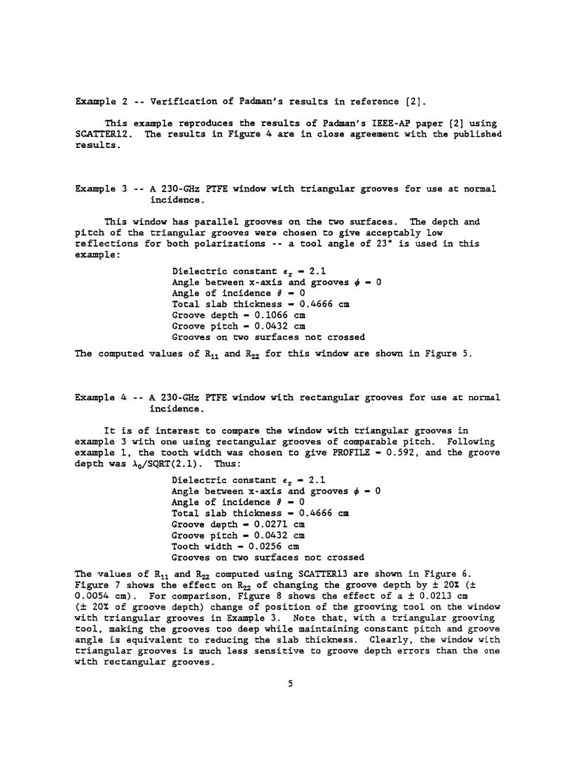
Example 4 -- A 230-GHz PTFE window with rectangular grooves for use at normalincidence.
It is of interest to compare the window with triangular grooves inexample 3 with one using rectangular grooves of comparable pitch. Followingexample 1, the tooth width was chosen to give PROFILE — 0.592, and the groovedepth was A0/SQRT(2.1). Thus:
Dielectric constant e r — 2.1Angle between x-axis and groovesAngle of incidence 8 — 0Total slab thickness — 0.4666Groove depth = 0.0271 cmGroove pitch — 0.0432 cmTooth width — 0.0256 cmGrooves on two surfaces not crossed
The values of R11 and P42 computed using SCATTER13 are shown in Figure 6.Figure 7 shows the effect on R .= of changing the groove depth by ± 20% (±0.0054 am). For comparison, Figure 8 shows the effect of a ± 0.0213 cm(t.. 20% of groove depth) change of position of the grooving tool on the windowwith triangular grooves in Example 3. Note that, with a triangular groovingtool, making the grooves too deep while maintaining constant pitch and grooveangle is equivalent to reducing the slab thickness. Clearly, the window withtriangular grooves is much less sensitive to groove depth errors than the onewith rectangular grooves.
5

Freq (GHz)R + R22
Fig. 5 . Example 3: A 230 GHz FTFE window with triangular grooves parallelon the two faces.
Fig. 6. Example 4: A 230 Gaz FTFE window with rectangular grooves parallelon the two faces.
6
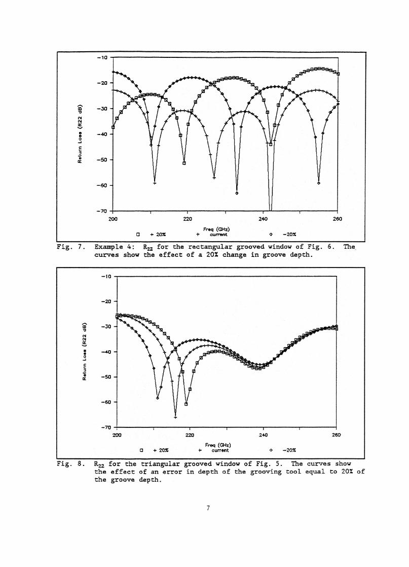
Fig. 7. Example 4: R22 for the rectangular grooved window of Fig. 6. Thecurves show the effect of a 20% change in groove depth.
Fig. 8. R22 for the triangular grooved window of Fig. 5. The curves showthe effect of an error in depth of the grooving tool equal to 20% ofthe groove depth.
7

ACKNOWLEDGMENT
We thank Rachael Padman for providing us with the original version ofSCATTER, and for her invaluable assistance with the program.
REFERENCES:
Eli R. Padman, "Program SCATTER - A Program for the Calculation of Plane.Wave Propagation in a Stratified Anisotropic Dielectric," CSIRO Divisionof Radiophysics Internal Report RPP 2031(L) , December 1976.
[2] R. Padman, "Reflection and Cross Polarization Properties of GroovedDielectric Panels," IEEE Trans. Antennas Prop., vol. AP-26, pp. 741-743.
8

APPENDIX I: CORRECTIONS TO THE ORIGINAL SCATTER REPORT AND CODE
One correction is necessary in the original Fortran code of programSCATTER (11: At the beginning of the listing of SCATTER, a comment definingPHI should be changed to read 'PHI, ANGLE BETWEEN THE NORMAL TO THE PLANE OFINCIDENCE (X-AXIS) AND THE GROOVES." In the current NRAO working versions ofSCATTER, a corresponding change has been made in the question which asks forPHI.
On page 3 of ref. [1], item (iii) should read "The optic axis is ...parallel to the surface of the dielectric andthe x-axis for all values of z...."
The example at the top of page 3 is made more consistent with theensuing discussion if it is changed to read "....if:4Sigen the optic axisof the dielectric lies in the 4 direction."
On page 16, the meaning is clearer if near the middle of the page,"...e is changed to read "...
• .
9

Calculation details:- Start frequency = 200.0000 GHz- Finish frequency = 260.0000 GHz- Frequency step = 30.00000 (NU- coupled PDEs solved by numerical integration in 50 steps
Frequency = 200.0000 GHzFY(0) = ( 1.000000 , 0. ) rx(o) -
( 1.000000 • a. )HX(0) = ( 1.000000
'
0. ) HY(0) =( -1.000000 0. )
Power check:- Perpendicular polarization = 1.000083- Parallel polarization ii. 0.9999956
Transmission matrix coefficients:- T11 =- T12 =- TZ1 =- • .22 -
(-0.9013337( 0.
,-0.42575840.
))
==
((
0.99683130.
, -154.71560.
.))
( 0. , 0. ) = ( 0. • 0. )(-0.8097652 ,-0.5827530 ) = ( 0.9976576 , -144.2591 )
APPENDIX II: DIALOGUE WITH SCATTER13 DURING EXECUTION OF EXAMPLE 1.
% scatter13This is scatter 13, used to analyze dielectrics withrectangular grooves.What is the angle between the X axis and the grooves (in deg.)?0Angle of incidence?0Number of steps for integration?50Dielectric constant?2.1Total slab thickness (cm.)?1.5Groove depth (cm) ?.0271Groove pitch (an) ?.0065What is the tooth width (cm.) ?.0038type the name of the output file (8 char with .prn)fig3.prnAre the grooves crossed (yin) ?
Print dielectric constant profile (yin) ?
Start frequency (GHz)?200End frequency (GHz) ?260frequency increment?30
Scattering parameters of grooved dielectric window:- normal to plan. of incidence at 0. degrees from groove axis- angle of incidence = 0. degrees
Window details:- Grooves on opposite faces are Parallel- Dielectric constant = 2.100000- Groove depth = 2.7100001E-02 an- Groove pitch = 6.5000001E-03 am- Slab thickness
▪
1.500000 an- Tooth Width 3.8000001E-03 an
10

CO-polar transmission losses:- =11 = 2.7566694E-02 dB- =22 = 2.0369722E-02 dB
Reflection matrix coefficients:- all = (-3.4194946E-02, 7.2398214E-02) . ( 8. 067453E-02. 115.2822 )• R12- R21 =
( 0. ,( 0. ,
0. )0. )
==
((
0. ,0. ,
0.0.
))
- R22 = (-3.9935470E-02, 5.5498242E-02) . ( 6.8373213E-02, 125.7381 )CO-polar reflection losses:- =11 = 21.93088 dB- RX22 = 23.30228 dB- VSWRX = 1.174072- VSWRY = 1.146782
Frequency = 230.0000 GiftI
FY(0) = ( 1.000000 0. ) FX(0) =( 1.000000 , 0. )
MO) = ( 1.000000'
0. ) RY(0) =( -1.000000 , 0. )
Power check:- Perpendicular polarization . 1.000231- Parallel polarization
•
1.000175TraIISMiS10.012 matrix coefficients:
- 211 = (-0.8169441 , 0.5692861 )- T12 = ( 0. , 0. )- T21 = ( 0. , 0. )- T22 . (-0.9253492 , 0.3793353 )
Co-polar transmission losses:- =11 = 3.7141792E-02 dB- =22 . -7.2270620E-04 dB
Reflection matrix coefficients:- all . ( -5.3473592E-02,-7.6729770E-02)- R12 = ( 0. , 0. )- R21 . ( 0. 0. )- R22 . ( 1.1129379E-03, 2.7239709E-03)
Co-polar reflection losses:RX11 = 20.58147 dB
- RX22 . 50.62550 dB- VSWRX = 1.206348- VSWRY = 1.005903
Frequency 260.0000 GazPY(0) = ( 1.000000
'
0. ) FX(0)( 1.000000 0. )
13X(0) = ( 1.000000'
0. ) RY(0)( -1.000000 , 0. )
Power check:- Perpendicular polarization = 1.000238- Parallel polarization . 1.000271
Transmission matrix coefficients:- T11 = ( 6.7534151E-02, 0.9873560 ) ( 0.9896629 ,- 212 = ( 0. , 0. ) = ( 0.- T21 = ( 0. • 0. ) = ( 0.- T22 = (-0.1676458 , 0.9857202 ) = ( 0.9998746
CO-polar transmission losses:- =11 . 9.0254329E-02 dB- =22 = 1.0893499E-03 dB
Reflection matrix coefficients:-All
. (-0.1439046 , 9.8483772E-03) = ( 0.1442412 ,
- R12 ( 0. , 0. ) = ( 0.R21 . ( 0. , 0. ) ( 0,
- R22 (-2.2512555E-02,-3.8339820E-03) = ( 2.2836692E-02,Co-polar reflection losses:
RX11 . 16.81821 dBRX22 . 32.82734 dBVSWRX = 1.337107
- VSWRY . 1.046741Do you want to run again (yin)'11
86.06714 )0. )0. )
99.65221 )
176 0850 )0. )0. )
-170.3351 )
= ( 0.9957331 , 145.1294 )= ( 0. 0. )
( 0. 0. )= ( 1.000083 157.7095 )
. ( 9.3524761E-02, -124.8730 )= ( 0. 0. )= ( 0. , 0. )= ( 2.9425578E-03, 67.77647 )
11

APPENDIX III : .PRN FILE PRODUCED BY SCA'TTER13 DURING EXECUTION OF EXAMPLE 1.
"This is scatter 13, used to analyze dielectrics with""rectangular grooves."" - normal to plane of incidence at " 0. ,"degrees from groove axis"" Angle of incidence is " 0."Window details:"" Grooves an opposite faces are Parallel" - Dielectric constant i s ', 2.100000" - Groove depth = ", 2.7100001E-02," cm"" Groove pitch = ", 6.5000001E-03," cm"" - Slab thickness = ", 1.500000 ," cm"" Tooth Width = ", 3.8000001E-03" cm""Calculation details:".. Start frequency = ", 200.0000 ," Gliz""- Finish frequency = ", 260.0000 ," Gliz"" Frequency step = ", 30.00000 ," Gas"" coupled PDEs solved by numerical integration in ", 50," steps"
"Freq. Gift.", "magill", "magT12", "magT21", "magT22", "magR11", "magR12", "magR21", "magR22"200.00, 0.9968, 0.0000, 0.0000, 0.9977, 0.0801, 0.0000, 0.0000, 0.0684230.00, 0.9957, 0.0000, 0.0000, 1.0001, 0.0935, 0.0000, 0.0000, 0.0029260.00, 0.9897, 0.0000, 0.0000, 0.9999, 0.1442, 0.0000, 0.0000, 0.0228
12