Embed Size (px)
Citation preview
BELL SYSTEM PRACTICES
AT&TCo Standard
SECTION 309-400-005
Issue 2, December 1980
1.
2.
3.
4.
5.
6.
1.
ELECTRONIC TANDEM NETWORK (ETN)
NETWORK ANALYSIS
SWITCHED SERVICE NETWORKS
CONTENTS PAGE
GENERAL . . . . . . . . . ..1
SPECIAL SERVICE SYSTEM (SSS) ANALYSIS
PLAN . . . . . . . . . . ..1
PERFORMANCE AND SURVEILLANCE REPORTS
.<. . . . . . . . . . . . . 4
NCOSS USAGE AND ANALYSIS . . . 4
NETWORK DESCRIPTION . . . . . . 6
REFERENCES . . . . . . . . ..8
GENERAL
# 1.01 This section covers network analysis for theElectronic Tandem Network (ETN) configuration.
Network analysis is assigned to a work centerwhich has a capability of analyzing trouble summariesand other reports for ETN.
1.02 This section is reissued to provide informationon analysis, and includes NCOSS usage.
Revision arrows are used to emphasize the moresignificant changes.
1.03 The Network Control Office (NCO) is assignedthe task of network analysis. Its objective
is to identify soft spots or potential trouble areason the network and to request remedial action priorto initiation of customer trouble reports. Theseduties are in addition to those defined in Sections660-005-011 and 309-400-001.
1.04 The NCO’s analysis is performed in additionto that performed by the Plant Control
Offices (PCOS) for those circuits which they control.The primary tool for this NCO function is the
Special Service System (SSS) plan, using the outputreports generated by it.
2. SPECIAL SERVICE SYSTEM (SSS) ANALYSIS PLAN
2.o1 The SSS Analysis Plan enables line and staffmanagers to access trouble history data for
aid in analyzing performance and planning needs.It also provides circuit inventory records includingcounts of serving links, priority codes, types ofcustomer provided equipment and other inventorydata to serving bureau and network managementpersonnel.
2.o2 The NCO will receive the following reportsautomatically after a Network Grouping
Identification (NGID) and a network inventory for$CLASS OF SERVICE 14 have been placed in thecomputer. An ETN NCO using an NGID appearsto the SSS computer to be a service manager.t(NGID for ETN is covered in Section 309-400-007.)
(a) Report 52: Network Detailed Trouble Listing
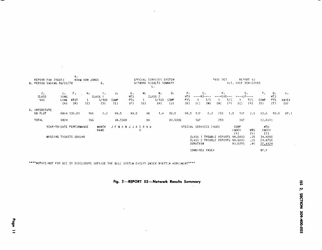
(b) Report 53:
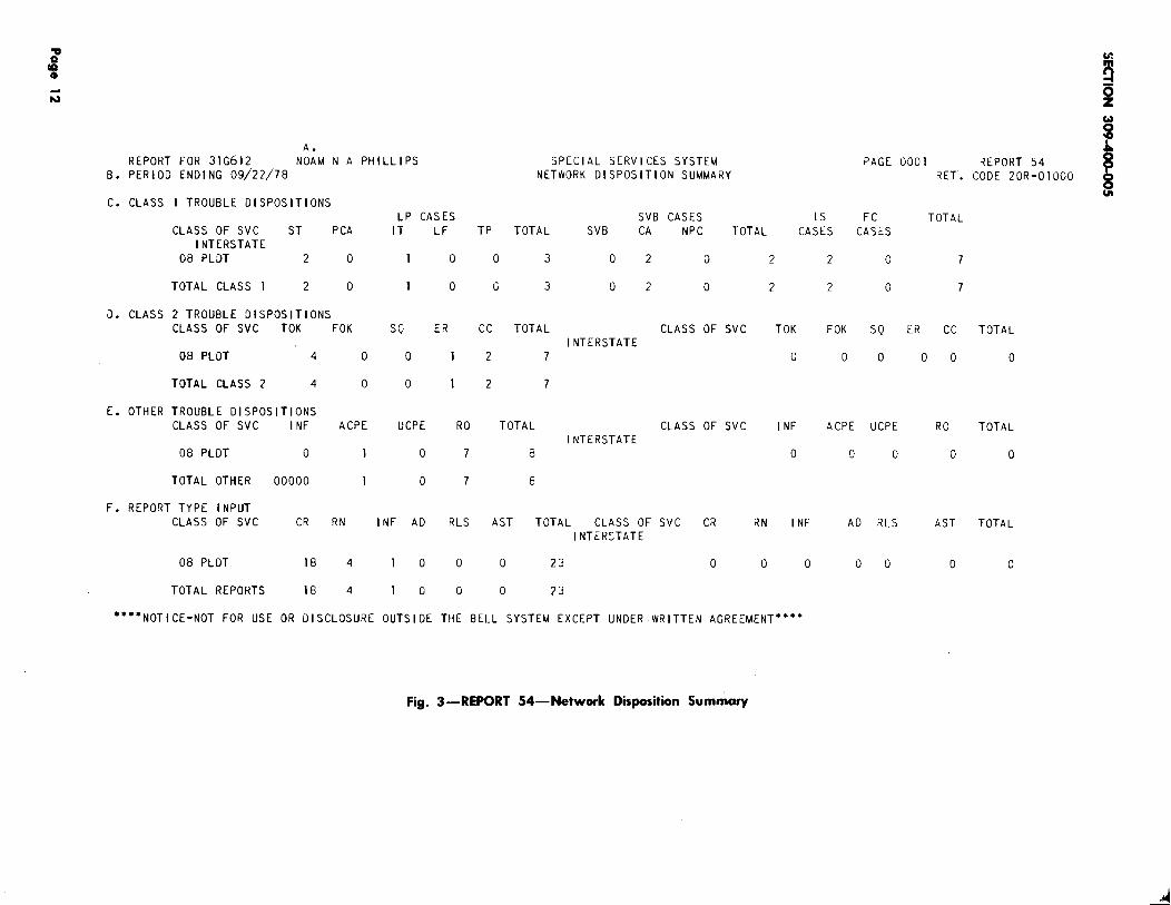
(c) Report 54:
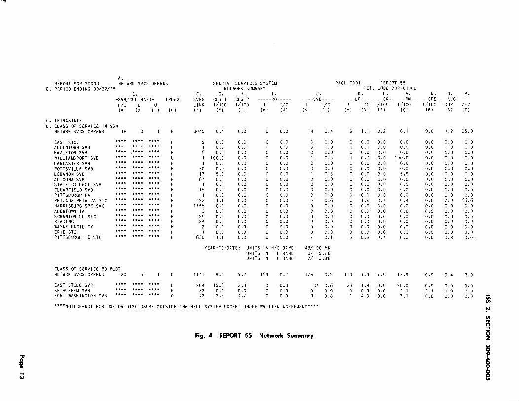
(d) Report 55:
(See Fig. 1.)
Network Results Summary (SeeFig. 2)
Network Disposition Summary(See Fig. 3.)
Network Summary (See Fig. 4.)
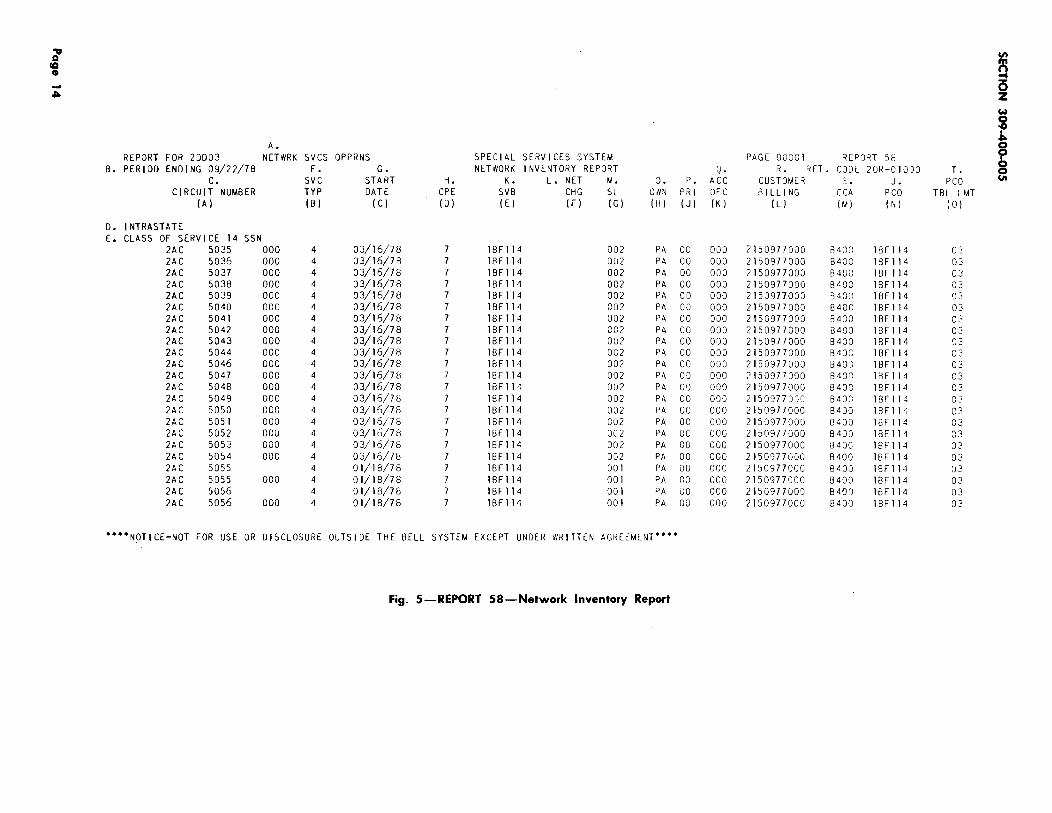
(e) Report 58: Network Inventory Report.(See Fig. 5.)
2.03 The reports mentioned above are describedin Section 660-225-106. Additional analysis
reports, Section 660-225-107, may be requested.
NOTICE
Not for use or disclosure outside the
Bell System except under written agreement
Printed in U.S.A. Page 1
SECTION 309-400-005
2.04 OThere are ten types of analysis reports NCO. The report types, mode of transmissionfrom the SSS plan that can be used by and turnaround time are as follows:
MODE OF OUTPUT TURNAROUNDTYPE DESCRIPTION TRANSMISSION TIME t
A Trouble Tally ADNet/Dataphone” Daily, Nightly
B Trouble Listing ADNet/Dataphone Daily, Nightly
c Detail Trouble Listing Mail T Weekly
D Circuit Tally ADNet/Dataphone Daily, Nightly
E Circuit Listing Mail Weekly
F Customer Dialing Analysis ADNet/Dataphone Nightly
G Trouble Code Summary Mail Nightly
I Index Mail Nightly
K Input-Output Summary Mail Nightly
L Mean Time Between Outage,Mean Time Restored,Percent Availability ADNet/Dataphone Nightly
+Turnaround time means frequency of processing.
*These reports will be mailed if the output exceeds 250 lines.
tRegarding all requests that are indicated as weekly turnaround, if the requestpasses the edits, the NCO will receive feedback on Monday morning via.
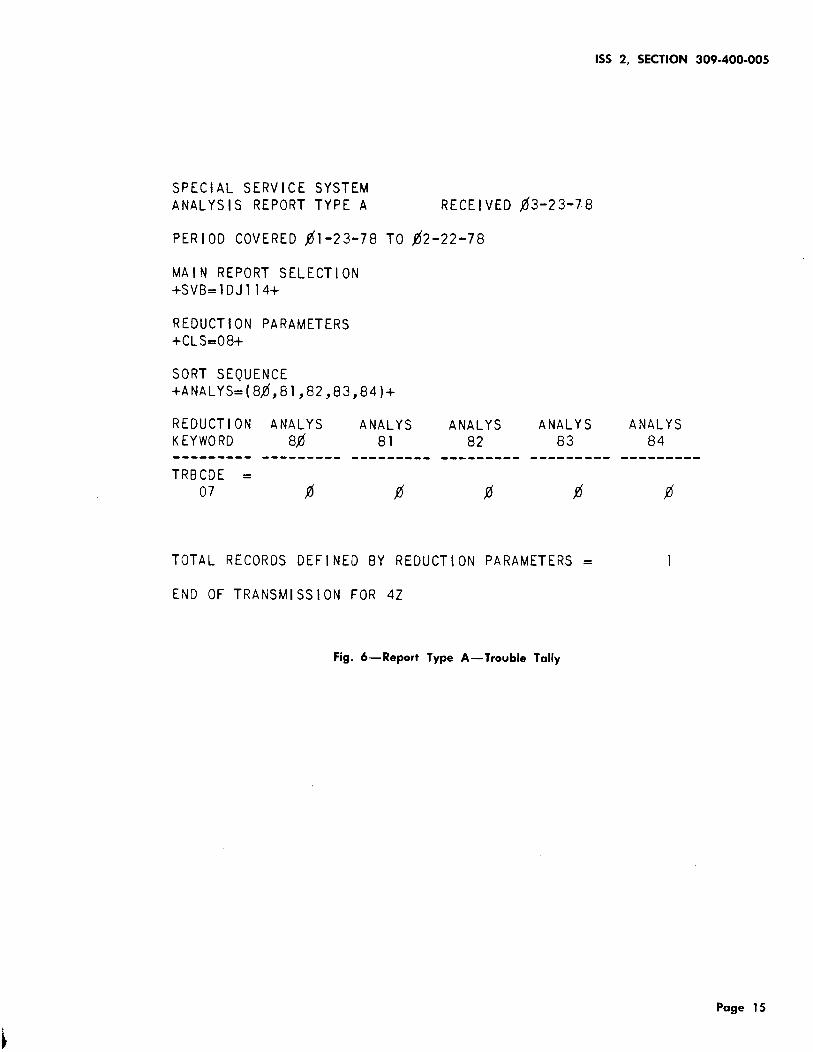
2.05 The Trouble Tally report (Type A) allowsthe retrieval of any information from the
trouble file in the form of a numerical tally. Thesereports are useful if a numerical total of troubleoccurrences is desired and not an actual listing ofthe data. One possible use would be to determinehow many customer reports were test OKS on PLdata circuits in a given period of time. (See Fig. 6.)
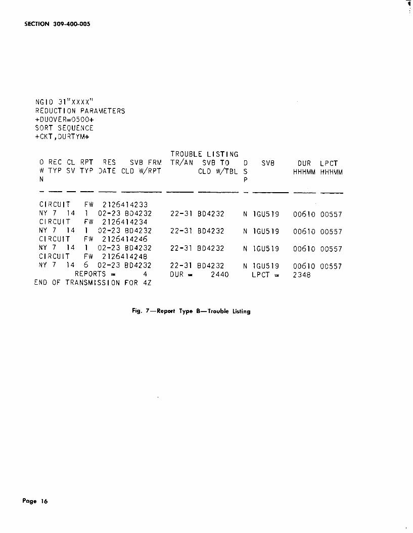
2.06 The Trouble Listing report (Type B) can beused when a listing is desired of all trouble
reports that would fit a given category. T-his willresult in a printout of all troubles on file for thespecified time period (previous month) and reductionparameters. An example of this would be anNCO requesting a listing of all troubles with aduration over five hours. (See Fig. 7.)
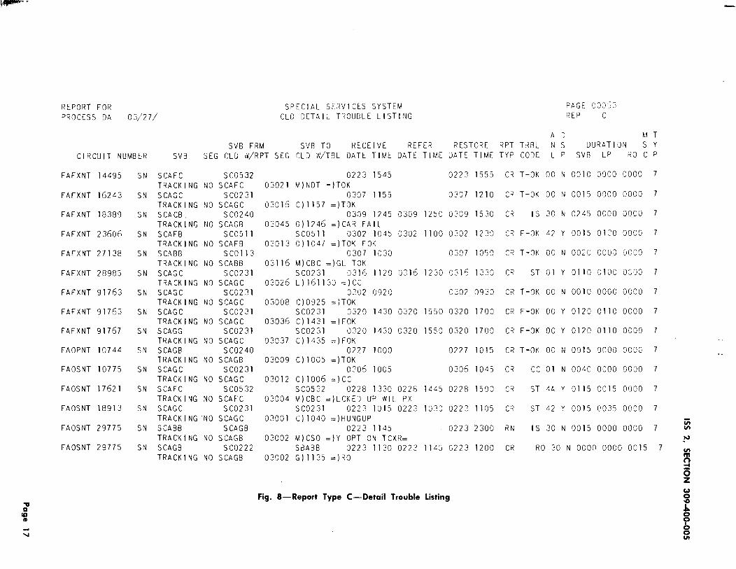
2.07 Detail Trouble Listing (Type C) from thetrouble file is designed for larger retrievals.
This report is available to the NCO for the previous
month using ETN NGID format. For example, aNCO could determine which tickets have over acertain amount of outage in a certain area. (SeeFig. 8.)
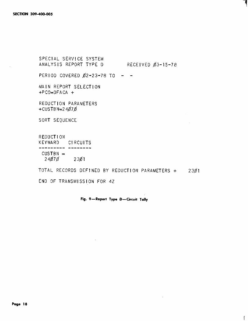
2.08 A Circuit Tally report (Type D) can be usedto obtain a tally of specific inventory data
for the previous month. For example, a PCO/NCOmay want a tally of circuits with a specific customerbase number. (See Fig. 9.)
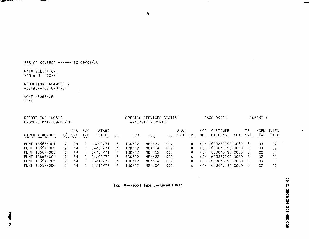
2.09 The Circuit Listing report (Type E) is helpfulif a selective inventory printout is desired.
For example a PCO or NCO may want a printoutof its circuit inventory for a particular customer.(See Fig. 10.)
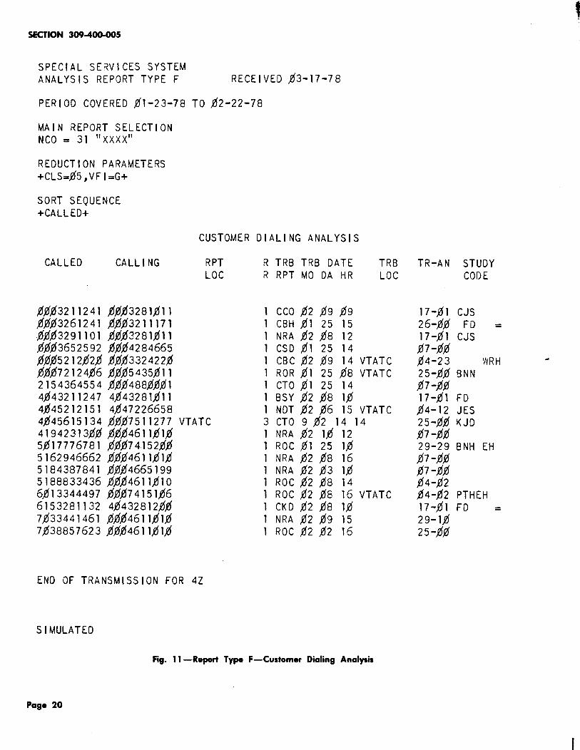
2.10 The Customer Dialing Analysis report (TypeF) is to be used to analyze Calling-Called
or Called-Calling reports on switched service troubles.A listing of all reports submitted with information
. . . .
1SS 2, SECTION 309-400-005
in Variable Field “G” on the E-6944 Trouble Ticketduring the specified time period is printed out. Itcan be sorted on either the Called number or theCalling number as desired. (See Fig. 11. )
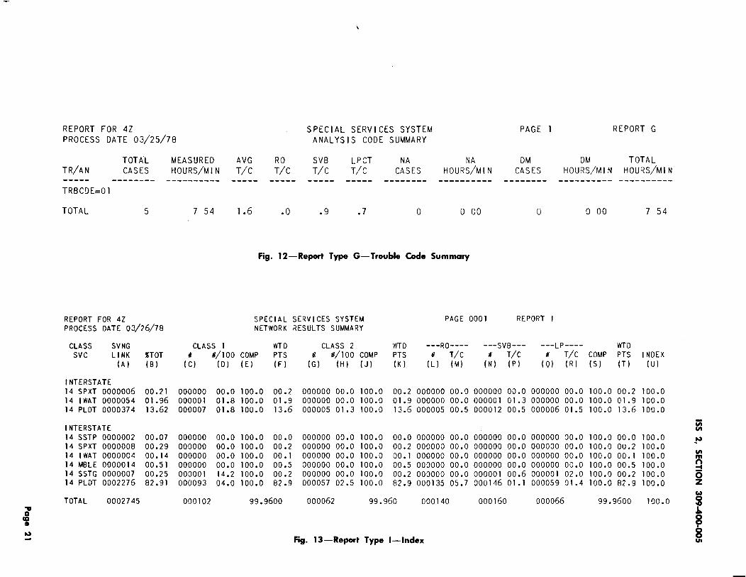
2. I I The Trouble Code Summary (Type G ) providesa breakout of Analysis Codes within Trouble
Codes. Figure llB shows the resulting printout.A request for information on a specific AnalysisCode can be made. (See Fig. 12.)
2.12 An Index report (Type 1) allows a study tobe made on a select group of circuits,
troubles, organizations, etc. For example a networkmay wish to look at its index for all customerreports and referred in cases. (See Fig. 13.)
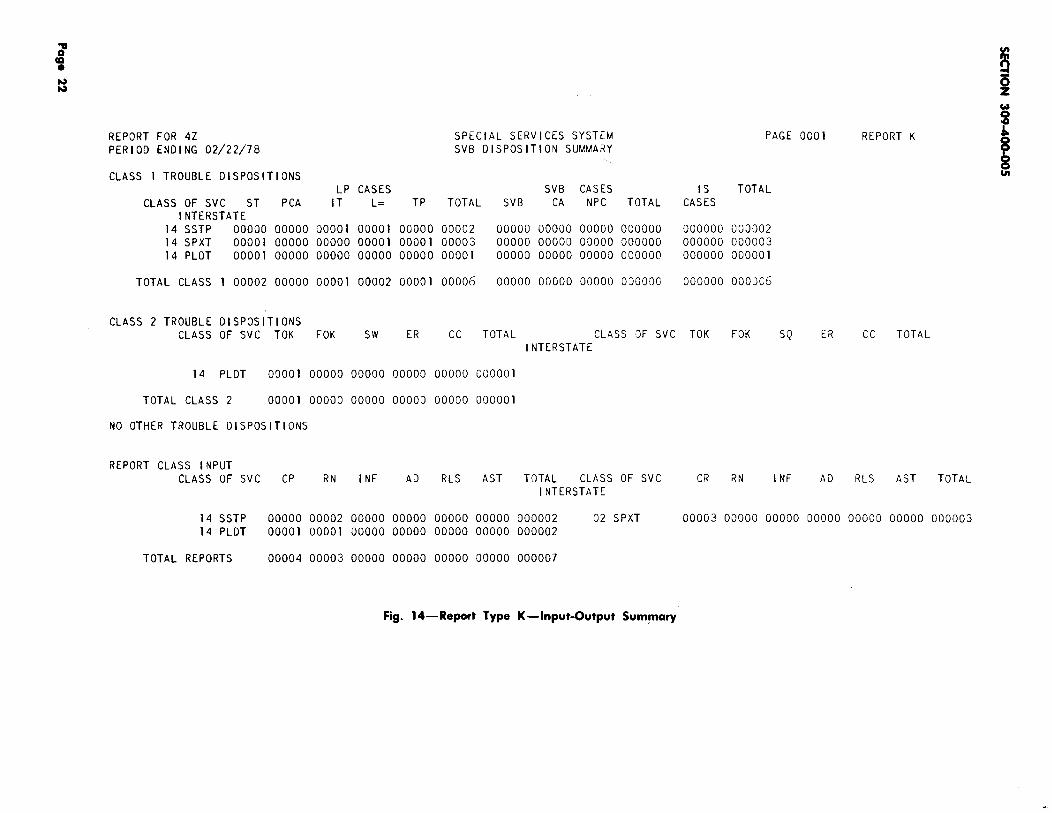
2.13 The Input-Output Summary report (TypeK) provides a summary of trouble disposition
and trouble ticket inputs by class of “service. (SeeFig. 14.)
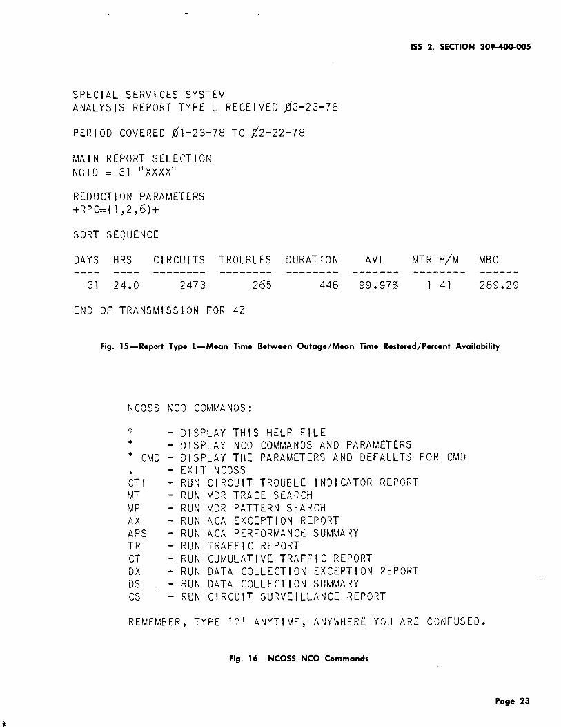
2.14 MBO-MTR-AVL report (Type L) is used tostudy the mean time between outages, mean
time to restore and the percent availability for agroup of circuits. For example, an NCO usingETN NGID could look at the parameters for theETN network. (See Fig. 15.) The formulas forfiguring MBO, MTR, and AVL are as follows:
(a) MBO = # Circuits x # Days
# Troubles
(b) MTR = Total Outage Hours
Total Outages
(c) % AVL = # of Days x 24 Hrs. x# of Circuits - Outage Time
# of Days x 24 Hrs. x
# of Circuits
When considering the use of the “L” Report thefollowing should be remembered.
(a) The L Report, if not given RPC = as areduction keyword, will give you all troubles
both measured and nonmeasured.
(b) If you see the RPC = Reduction keywordand the main selection is NGRPID, be careful
not to double count the troubles. For example:if you say RPC = (1, 2) you will be doublecounting the troubles because all referred-introubles start out as some other type of trouble.t
2.15 In order to provide meaningful results andeffective analysis, an accurate circuit inventory
must be maintained. Each serving bureau isrequired to input an inventory ticket, supplyingserving link counts and related data for eachcustomer location district (CLD) termination. ThePCO supplies overall circuit data such as class ofservice, customer billing number, etc. Receipt ofthe inventory report will allow the NCO to verifythat all circuits on the network have been enteredinto the plan by the responsible PCO.
2.16 If circuits are missing from the inventory,the NCO must advise the responsible PCO
to enter the circuits into the plan. Likewise,discontinued circuits must be removed from theinventory.
2.17 The detailed trouble listing will provide theNCO with a list of troubles that have occurred
within the last report period. Repeat reports arereadily seen and, if it appears that no trouble hasbeen found, the NCO should contact the responsiblePCO and verify that positive action will be takento resolve the problem. The NCO may suggestthat a routine inspection of the circuit is in order.Follow-up is required to insure satisfactory results.
2.18 9The PCO will use the administration circuitnumber for non-circuit specific troubles (ie,
calling-called number trouble reports). This willenable the PCO and NCO to perform analysis todetermine faulty circuits (BSP 660-225 -ZZZ).
2.19 Transmission results will be entered intothe SSS plan on a monthly basis. The results
are available on a monthly printout.t
(a) Manual Circuit Measurements will be scheduledon an annual basis. These will include
transmission and noise. The monthly report willshow 12-month period results.
(b) Automatic circuit measurements (ie, circuitsthat can be measured by CAROT) are
measured on a monthlyprinted out monthly.
basis and the results
Page 3
SECTION 309-400-005
3. PERFORMANCE AND SURVEILLANCE REPORTS
3.o1 The automatically generated SSS reports willassist a qualified analyzer in identification
of soft spots and potential troubles. When reportsindicate less than satisfactory performance, detailedanalysis of troubles and maintenance activities canlead to appropriate corrective action.
3.02 The NCO is responsible for generating amonthly report depicting overall network
service and performance. This report should bedistributed to Marketing (upon request), uppermanagement and the various responsible workcenters.
3.o3 The SSS on ETN produces results andsummaries based upon a monthly reporting
period. The NCO monthly network summary includesthe following (some of this information is obtainedfrom the SSS results on ETN):
(a) Service order performance
(1) Total orders due
(2) Number on time
(3) Percent on time.
(b) Circuit maintenance performance
(1) Results
(2) Class 1 (found) troubles
(3) Class 2 (not found) troubles
(4) Duration time.
(c) Service characterization (from Report “L”)
(1) Meantime between outages (MBO)
(2) Meantime to repair (MTR)
(3) Percent availability (% AVL)
(4) MBO - MTR - AVL.
(d) Work center portion of organizational summaryfor work center involved.
(e) The NCO may add pertinent remarks (optional)concerning network operation. These remarks
may be comments regarding major failures, theircause and affects on the network. Appropriatecomments concerning major changes to thenetwork or other items of interest may also beincluded.
3.o4 The service order component of the reportis manually generated from the NCO record
of service order and completion information onnetwork service orders due in a report period.
3.OS The circuit maintenance performance reportis derived from the Network Results
Summary, SSS Report 53 (Section 660-225-106).To obtain this report, the NCO must use a networkgrouping identification number (Section 309-400-007)and input inventory tickets per Section 660-225-102.Once an accurate inventory has been established,it must be continually updated.
3.06 The NCO cannot submit inventory ticketsuntil the PCOS have fulfilled their responsibilities
to SSS. In this manner the NCO will be able toverify that network circuits have been inventoried.The NCO will receive a monthly Network InventoryReport, Report 58 (Section 660-225-106), for thispurpose.
3.o7 Service characterization for the network isoriented toward circuit performance. This
report may be used by marketing in discussingperformance with the customer. This SSS output,Analysis Report “L” (Section 660-225-107), mustbe requested by the NCO.
3.08 The work center summary is a characterizationof the performance of an individual work
center. These results are transmitted with thefirst three parts of the network summary, only tothe involved work center. The information forthis portion of the report is derived from theNetwork Summary Report 55, (see Section 660-225-106)and compares the individual work center performanceto that of the total network.
4. NCOSS USAGE AND ANALYSIS
4.o1 The Network Control Operations SupportSystem (NCOSS) performs network support
functions for ETNs. In this ETN network, supportrole NCOSS is a tool for both the NCO, theorganization with overall ETN Installation and
Page 4
lMaintenance (I&M) responsibilities, and the BusinessServices team, responsible for traffic networkadministration for a particular ETN. From theNCO user perspective, NCOSS permits access toMessage Detail Record (MDR) data, Facilities TrafficMeasurement (FTM) data and Automatic CircuitAssurance (ACA) data derived from the tandemswitches in the ET’NTfor which that NC() has I&Mresponsibility. These data elements, describedbelow, are available through a set of reports andsearches specified by the NCO to permit accurateand timely network trouble localization (eg, to aparticular network node or a particular circuit).
Message Detail Recording (MDR)
Details of each network call including ineffectiveattempts
Calling, called numbers
Circuit groups and members
Timing information
Call privileges information
Special call indicators
FACILITY TRAFFIC MEASUREMENTS(FTM)
Hourly measurements on trunk group and queuetraffic including peg, usage, overflow, etc.
A UTOMA TIC CIRCUIT ASSURANCE (A CA)
Circuits identified with exceptionally short or longholding time calls (DIMENSION tandems only)
NCOSS usage usually covers two to four weeksprior to cutover and includes call throughs, ifscheduled, and remains for two to six weeks after
. cutover to help resolve network trouble. In addition,..NCOSS may be used on a revisit basis (two to sixweeks) to help resolve difficult maintenance problems.
4.02 The NCO has access to the data in NCOSSfor the ETN it is responsible for by using
a remote terminal and a dial Up connection to theNCOSS computer. The NCO uses NCOSS in fourmajor areas.
(a) Response to customer troublereports—The NCO accesses NCOSS in
response to a customer trouble report, referredby the PCO, to determine if a trouble existsand to localize the trouble to a tandem node ora specific circuit. After the trouble is locaiized,the NCO refers the trouble to the specific workcenter that is responsible for the repair.
(b) Major Problem Detection–Through theexamination of the MDR, ACA and FTM
data in proper processed form, the NCO detectsand localizes the source of a major networkproblem affecting network call completion (eg,multiple outages in a circuit group, networkswitch failures to seize circuits in the circuitgroup).
(c) Network Performance Monitoring–Usingsummarized ACA statistics, the NCO examines
the performance of the network as a whole andof individual TELCO work centers responsiblefor the performance of particular elements ofthe network. In particular, if the networkperformance monitoring indicates sub-parperformance, the NCO determines if this is dueto specific soft spot and identifies the responsiblework center.
(d) Trouble Pattern Analysis–Based on anumber of correlated customer trouble reports
and/or other network performance indicators,the NCO uses the MDR and ACA data to analyzepatterns of troubles and to locate sources oftroubles that would otherwise remain undetected.
4.03 Figure 15 fi~ovik a .Iist of commands thatthe NCO can use to get ske~ific information
from NCOSS.
4.o4 The following commands are frequently usedby the NCO to access NCOSS reports for
analysis and trouble localization.
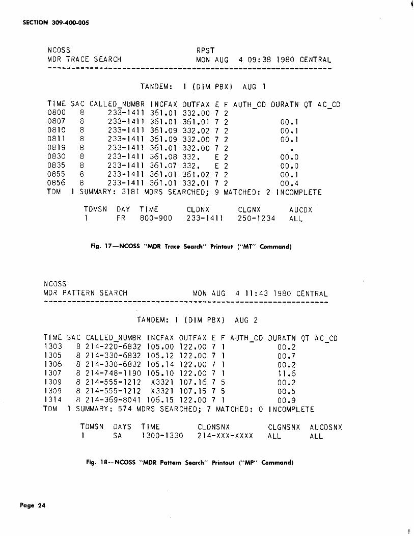
(a) BY using the “MT” command, the NCO canget data from NCOSS to assist in identifying
specific circuits that were involved in a reportedtrouble. This type trouble is normally a non-circuitspecific (called/calling) type report. The NCOSSreport (see Fig. 17) displays the called number,the calling number, the Trunk Dial Access Codeand member number of the circuits used forthe call. It displays both incoming facility orstation number and the outgoing facility. -
Page 5
(b) The “MP’> commandfor trouble analysis
following specific items:
provides NCOSS dat~for any one of the
(a)
(b)
(c)
(d)
(e)
(f)
(g)
(h)
(i)
Calling number
Called number
Authorization code
Dial access code incoming
Dial access code outgoing
Facility restriction level
Event code
System access code
Short holding time (variable time asrequested).
Figure 18 is an example of an NCOSS printout toa specific NPA(214) for a given time period from1300 to 1330 on a given day.
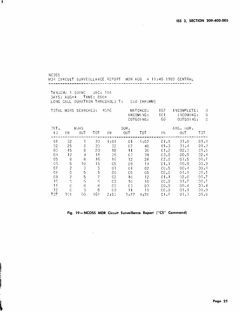
(c) The “CS” command is used to provide usageby a specific dial access group. It can be
used to determine the trunk usage of each trunkin the dial access group. Figure 19 is a sampleof this report. A given trunk with high usageand low average duration, either in or out wouldbe suspect as a faulty circuit. Low or no usageindications for a trup.k- .c~~j~ also indicate apossible trunk problem. --
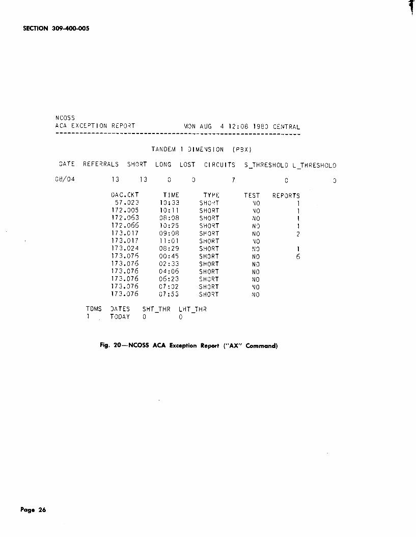
[~~ Automatic Circuit Assurance (ACA) is availableto the NCO either through “CACS” or from
NCOSS if the particular ETN customer does nothave a CACS. Figure 20 is an example of anNCOSS provided ACA report by using the “AX”command. The report indicates the trunk dialaccess code, the member or circuit number, thetime of the ACA occurrence, the type (longholding time or short holding time), whetherthe customer attendant tested the circuit andthe number of reports for a circuit for a giventime period. In this example, DAC 173 circuit07.6 had 6 short holding times which may indicatea circuit trouble.
4.0s The JNC() should use the “NCOSS How toOperate” book as a guide for accessing and
inputting the y~arious commands for data fromNcoss.
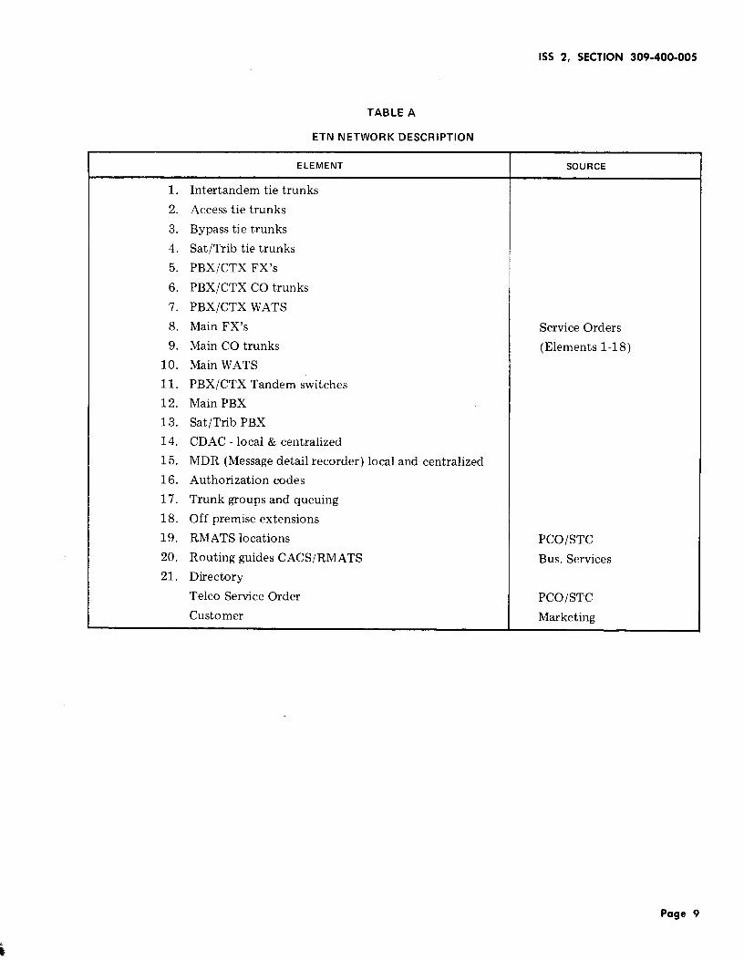
5. NETWORK DESCRIPTION
5.01 The NCO is required to maintain an accuratenetwork description. Table A lists the
elements and sources for this document.
5.02 The required information for eachnetwork-related element is delineated below.
For the circuits (elements 1 through 10, Table A)the following items are required by group.
● Trunk group identification number andnumber of circuits
● Terminal PBX/CTX’s
● Control office
● Telphone number of control office
● Bell System or OCC circuit indicator.
5.03 For off-net facilities the following should beprovided:
●
●
5.04
NNX’S served if not available in routingguide (elements 5, 6, 8 and 9)
Band NNX’S if not available in routing guide(elements 7 and 10).
For the PBX and tandem switchers (elements11, 12 and 13) the following should be
retained:
●
●
●
●
●
Location
Type of vehicle
DDD and network telephone
Attendant telephone number
number
and alternate
Repair ServiceControl Center
Bureau (RSB) or Switching(SCC) responsible
Page 6
1SS 2, SECTION 309-400-005
● Telephone number of responsible RSB orScc
5.09 For developing information on Dimension@switches, the following data on the Remote
Maintenance Administration and Traffic System(RMATS) vehicle (element 19) is required:.-. Additional RNX if used (RNX is a restricted
network address code)● Location
● Network and DDD (local) access codes (ie,$8= NTWK, 9= LOCAL or DDD4 ). ● Telephone number
5.05 The CACS and Message Detail Recording(elements 14 and 15) require the following
information:
● PBXS covered by RMATS.
5.10 The Network routing guide (element 20)including each PBX/Centrex tandem is needed
for:● Location
● Telephone number and alternate ● Automatic alternate routing
● RSB responsible ● Automatic route selection.
● RSB telephone number. 5.11 The directory (element 21) is a listing ofspecial customer and TELCO phone numbers.
The numbers needed are:5.06 Authorization codes (element 16) shouldinclude the
● Customer number for CACS● Availability (PBX/Centrex tandem basis)
● TELCO numbers for Marketing, BusinessServices and Engineering.● Portable or stationary codes (or both).
5.o7 The details of queuing (element 17) in thenetwork needed are:
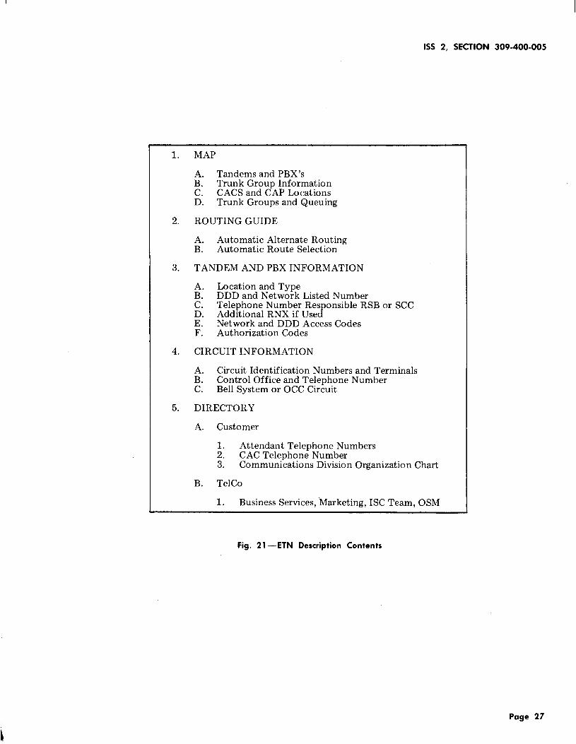
5.12 The information listed in Table A should bemaintained in an ETN book with a
recommended format shown in Fig. 21 through 24.● Trunk groups with queuing
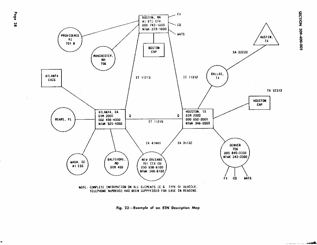
5.13 A network map (Fig. 22) should be developedto provide most of the required information
in a readily accessible format. This map shouldcontain the following items.
● Type of queues
● Location of queues
● Queue slots provided. ● PBX/CTX tandems, main PBX’S andsatellite/tributary PBX’S
5.08 The required information for off premiseextensions (element 18) include: ● Trunk group identities including DAC’S and
RNX’S● Location
● CACS and MDR● Network telephone number
● Trunk groups with queuing (indicated by
“Q”)● Circuit identification number if available
● $For DIM FP8, indicate circuit pack type(LC02 or, LC361).4
● Network and DDD listed numbers
● Interexchange off premise extensions.● Control office
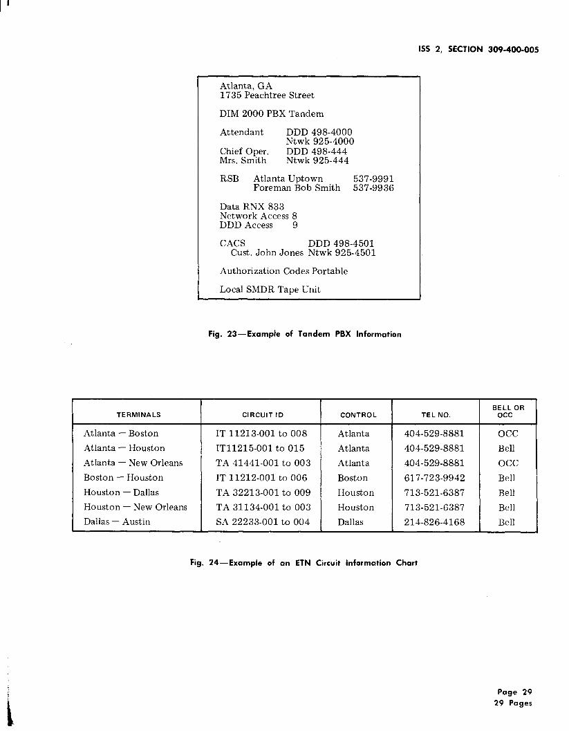
5.14 Additional information concerning a tandemsubtending PBX’S should be developed (see● Control office telephone number.
Page 7
SECTION 309-400-005
Fig. 23). Information on FX’S, WATS, and COtrunks used for automatic off network calls shouldbe listed on this page where applicable. Alsoinclude the data RNX (if any), the authorizationcode information, RMATS location (if applicable),and SMDR capabilities.
S. 1s Circuit information, Fig. 4, should be listedseparately due to the need for updating.
The Common Language Circuit Identification codesare:
● IT - Intertandem Tie Trunk
● SA - Satellite Tie Trunk
SECTION
309-400-002
309-400-004
309-400-007
309-400-300
660-225-100
660-225-101
660-225-102● TA - Tandem Tie Trunk.
5.16 A directory of telephone numbers not includedwith circuit and tandem information should
also be included. Numbers for Marketing, BusinessServices and other TELCO support groups may beincluded. An organization chart of the customer’scommunications division may be included in thesection along with the appropriate numbers. Otherinformation may be included as necessary.
5.17 The NCO should arrange to distribute a copyof this information to all PCOS, Switching
Control Centers (SCCS) and RSBS. It is suggestedthat RSBS arrange for the document to be left atFP8 tandem locations.
6. REFERENCES
6.01 The following Bell System Practices arerelated to this section.
SECTION TITLE
309-400-000 ETN General Description
309-400-001 General Procedures and Responsi-bilities
660-225-103
660-225-104
660-225-105
660-225-106
660-225-107
660-225-108
660-225-109
795-402-100
TITLE
CACS/CAP/$LCAS4
Trouble Reporting
Network Identification
Service Maintenance
Special Services System–General
Special Services System–GeneralProcedures and requirements
Special Services System–GeneralInput Documents, E-6948, E-6945,E-6946
Special Services System InventoryTicket E-6943
Special Services System TroubleTicket E-6944
Special Services System–GeneralIndex Plan and Weighting Tables
Special Services System–Output,Reports and Results Summaries
Special Services System AnalysisPlan
Special Services System BillingAdjustments and Billing Reports
Special Services System–SpecialOutputs and Summaries
Bell System Common LanguageSpecial Service Circuits
Page 8
1SS 2, SECTION 309-400-005
TABLE A
ETN NETWORK DESCRIPTION
ELEMENT SOURCE
1. Intertandem tie trunks
2. Access tie trunks
3. Bypass tie trunks
4. Sat /Trib tie trunks
5, PBX/CTX FX’S
6. PBX/CTX CO trunks
7. PBX/CTX WATS
8. Main FX’S Service Orders
9. Main CO trunks (Elements 1-1 8)
10. Main WATS
11. PBX/CTX Tandem switches
12. Main PBX
13. Sat/Trib PBX
14. CDAC - local & centralized
15. MDR (Message detail recorder) local and centralized
16. Authorization codes
17. Trunk groups and queuing
18. Off premise extensions
19. RMATS locations PCO/STC
20. Routing guides CACS/RMATS Bus. Services
21. Directory
Telco Service Order PCO/STC
Customer Marketing
Page 9

m
Yg
A. f
REPORT FOR 2DD03 NETWRK SVCS OPPRNS SPECIAL SERVICES SYSTEM PAGE 00013 REPORT 52
B. PERIOD ENDING 09/22/78 NETWORK DETAIL TROUBLE LISTING RET. CODE 2DR-O1OOO 8
CIRCUIT NUMBER
INTRASTATECLASS OF SERVICE 08
D. 6FDDC 10I2
6FDDC 1012
6FDDC 1012
6FDDC 1012
6FDDC 1013
6FDDc 1013
6FDDC 1013
E. F. G.
SVB FRMSVB SEG CLD W/RPT
PLDT
1BF425 DD3188X.TRACKING NO IBF425
. DEABA 1BF425TRACKING NO IBF425
IBF425 1DD3188TRACKING NO 1BF425
DBAEA 014 IBF425TRACKING NO 1BF425
1BF425 DD31B8TRACKING NO 1BF425
DDBEA IBF425TRACKING NO IBF425
DDBEA 1BF425TRACKING NO 1BF425
. MISSING TICKET = M IN TYP COLUMN
gH. 1. J. K. L. M. N. O. P. Q. R. S. T. U. V. W.
AD CMPTSVB TO RECEIVE REFER RESTORE RPT TRBL N S DURATION CSRY
SEG CLD W/TBL DATE TIME DATE TIME DATE TIME TYP CODE L P SVB LP ROA C I P
DEABA 0915 0952 0915 0955 0915 1345 CR RO N 0000 0000 0003 0712854 =) SEND HAN SEG IN FOK<
Y.0915 0955 0000 0000 0000 0000 RN 0000 0000 0000 OM
12854
DBAEA 0918 1000 0918 101D 0918 1125 CR RONM N 0000 0000 0010 0712881
01412881
11794
11794
12857
M)CSO =)SEG 14 FOK E6700<
DB1813 0918 1000 D918 1001 0918 1047 RN ACPE 76 Y 0001 0046 0000 M07D)O9181OOICHO9I81O47 1431 VERNON RD H)CHCHCSO =)CPE TBL<
DDBEA 0823 1445 0823 1455 0823 2055 CR RO N 0000 0000 0010 07=)LINE DOWN SEG B CABLE CROSS JHTN TO STN<
005167 0823 1450 0823 1455 1823 2055 RN LF 11 N 0005 0600 0000 07M)FOR =)BAD CA PR AT JNTWN <
005167 0915 1048 0915 1050 0915 1100 RN IT 31 N 0002 0010 0000 07M)NSY =)CHANGEO RESTORAL UNIT<
“*** NOTICE - NOT FOR USE OR DISCLOSURE OUTSlOE THE BELL SYSTEM EXCEPT UNDER WRITTEN AGREEMENT ● “*”
Fig. l—REPORT 52—Network Detailed Trouble listing
A.
REPORT FOR 21 GUT3 NOAM DOW JONESB. PERIOO ENDING 09/22/78 G.
c. E. F. , H. 1.CLASS SVNG CLASS I
Svc LINK %TOT 1/100(A) (B) (:) (o)
O. INTERSTATE08 PLDT 6924 100.00 166 2.3
TOTAL 6924 166
YEAR-TO-DATE PERFORMANCE MONTHBAND
MISSING TI CKETS 000040
sPECIAL SERVICES SYSTEM PAGE 001 REPORT 53
NETWORK RESULTS SUMMARY RET. CODE 2OR-O1OOO
L.
J. K. M. N. o. P. Q. R. s. T. U. v.WTo CLASS 2 WT17 ----R O---- ----SVB --- ----L P---- WT O
COMP PTS 1/’100 COMP PTS T/C T/C 1/’ C COMP PTS
(E)
I NOEX(F) (:) (H) [J) (K) (:) (M) (1) (P) (;) (R) (s1 (T) (u)
99.5 99.5 99 1.4 99.5 99.5 107 0.3 259 1.0 107
99.5000 99 99.5000 107 259 107
JFMAMJJA SONO SPECIAL SERVICES INDEX COMPo INOEX
(x}CLASS 1 TROUBLE REPORTS 99.5000CLASS 2 TROUBLE REPOQTS 99.5000DURATION 93.63Io
COMB INEO INDEX
●“”” NOTICE-NOT FOR USE OR DISCLOSURE OUTSIDE THE 8ELL SYSTEM EXCEPT UNOER WRITTEN AGREEMENT***”
Fig. 2—REPORT 53—Network Results Summary
3.9 93.6 93.5 97.1
93.6310
WTD‘WTG INOEX(Y) [z).35 34.8250.25 24.8750.40 37.4524
97.2
a’mCD
m?j
Gz
u?
5~~
A.REPORT FOR 31G612 NOAM N A PHILLIPS SPECIAL SERVICES SYSTEM PAGE 0001 REPORT 54 8
B. PERIOD ENDING 09/22/78
C. CLASS I TROU8LE DISPOSITIONS
CLASS OF SVC ST P CAINTERSTATE
08 PLOT 2 0
TOTAL CLASS 1 2 0
D. CLASS 2 TROU8LE DISPOSITIONSCLASS OF SVC TOK FOK
08 PLDT 4 0
TOTAL CLASS 2 4 0
E. OTHER TROUBLE DISPOSITIONSCLASS OF SVC I NF ACPE
08 PLDT o 1
TOTAL OTHER 00000 1
F. REPORT TYPE INPUT
NETWORK DISPOSITION SUMMARY RET. CODE 20R-01000kul
LP CASES SVB CASES Is FC TOTALIT
1
1
SQ
o
0
uCPE
o
0
CLASS OF SVC CR RN INF AD
08 PLOT 18 4 10
TOTAL REPORTS 18 4 10
LF TP TOTAL SVB CA NPC TOTAL CASES CASES
o 0 3 02 0 2 2
0 G 3 02 0 2 2
ER CC TOTAL CLASS OF SVC TOK FOK
INTERSTATE
12 7 0 0
12 7
RO TOTAL CLASS OF SVC I NF ACPEINTERSTATE
7 8 0 0
7 e
o 7
0 7
SQ ER CC TOTAL
o
UCPE
o
RLS AST TOTAL CLASS OF SVC CR RN I NF AD 2LSINTERSTATE
o 0 23 0 0 0 00
0 0 23
00 0
RO TOTAL
o 0
AST TOTAL
o 0
●***NOTICE-NOT FOR USE OR DISCLOSURE OUTSIDE THE 8ELL SYSTEM EXCEPT UNDER WRITTEN AGREEMENT****
Fig. 3—REPORT 54—Network Disposition Summary
A.
B.
c.D.
REPORT FOR 20D03 NETWRK SVCS OPPRNS––, .-,_-PF.RIOD ENOING 09/2Z/18
E.-SVB/’CLO BAND-
H/O(A) (b) (:)
INTRASTATECLASS OF SERVICE 14 SSNNETWRK SVCS OPPRNS
EAST STC.ALLENTOWN SVBHAZLETON SVBWILL I AMSPORT SVBLANCASTER SVBPOTTSVI LLE SVBLEBANON SVBALTOONA SVBSTATE COLLEGE SVBCL EARFIELO SVBPITTSBURGH PAPHILADELPHIA 2A STCHARRISBURG SPC SVCAL ENTOWN I ASCRANTON LL STCREAOINGWAYNE FACILITYERIE STCPITTSBURGH I E STC
18 0 I
● *** ● *** ● ***● *** ● *** ● ***● *** ● *** ● ***● *** ● *** ● ***● *** ● *** ● ***● *** ● *** ● *.*● *** ● *** ● ***● *** ● *** .***● *** ● *** ● ***● *** ● *** ● ***● *** ● *** ● ***..** ● .** ● ***● *** ● *** .***● **. ● *** ● ***● *** ● *** ● ***● ,** ● *** ● *.*● *** ● *** ● ***.*. * ● *.* ● **.● *** ● *** ● *.*
CLASS OF SERVICE 80 PLDTNETWRK SVCS OPPRNS Zo 5 1
EAST STCLO SVB ***. .*** ● .**
BETHLEHEM SVB ● *** ● *** ● ***
FORT WASHINGTON SVB ● *”” ● “*” ““””
INDEX
(o)
H
HHHuHHHHHHHHHHHHHHH
o
LHo
F.SVNGLINK(E)
3045
9
:11
301767
116
1423
17563
5624
2
63;
SPECIAL SERVICES SYSTEMNETWORK SUMMARY
G.
CLS 11/100
(F)
0.4
0.00.00.0
100.30.00.05.80.00.00.00.0I.10.00.00.00.00.00.01.1
H.CLS 21/1 00
(G)
0.0
0.00.00.00.00.00.00.00.00.00.00.00.00.00.00.00.00.00.00.0
1.
-----RO -----
(L
0
0000D0i)000000000000
T/C
[J)
0.0
0.00.00.00.00.00.00.00.00.00.00.00.00.00.00.00.00.00.00.0
YEA R-TO-OATE: UNITS IN H/O BANOUNITS IN L BANOUNITS IN U BANO
1141 9.9 5.2
204 15.6 2.432 0.0 0.042 2.3 4.7
“*”” NOT I CE-NOT FOR USE OR DISCLOSURE OUTSIOE THE BELL SYSTEM ExCEPT UNOER
169 0.2
0 0.00 0.00 0.0
J.----SVB ----
(;)
14
000I001000050000007
l/L
(L)
0.4
0.00.00.00.50.00.00.50.00.00.00.00.60.00.00.00.00.00.00.1
48/ 90.6%3/ 5.7Z2/ 3.8%
174 0.5
37 0.60 0.03 0.8
WRITTEN AGREEMENT””””
PAGE 0001 ?EPORT 55RET. COOE 2OR-O1OOO
K. L. M.----L P---- --cR -- __RM-_
oil
9
0001000000030000005
110
3301
T/C(N)
I.1
0.00.!)0.00.70.00.00.00.00.00.00.01.80.00.00.00.00.00.00.8
1.9
1.40.04.0
1/100(P)
0.2
0.00.00.00.00.00.00.00.09.00.00.00.70.00.00.00.00.00.00.7
17.6
0.00.00.0
I,/loo
(Q]
0.1
0.00.00.0
100.00.00.05.80.00.00.00.00.40.00.00.00.00.00.00.3
13.9
20.03.17.1
N. o.-- CPE -- AVG
I/loo(R)
0.0
0.00.00.00.00.00.00.00.00.00.00.00.00.00.00.00.00.00.00.0
OUR(s)
1.2
0.00.00.00.00.00.00.00.00.00.00.02.00.00.00.00.00.00.00.8
P.
Z+2(T)
25.0
0.00.00.00.00.00.00.00.00.00.0
6;:;0.00.00.00.00.00.00.0
0.9 0.4 3.9
0.9 0.0 0.03.1 0.0 0.00.0 0.0 0.0
Fig. 4—REPORT 55 —Network Summary
A.
REPORT FOR 2DD03 NETWRK SVCS OPPRNSB. PERIOD ENDING 09/22/78
. .
c.CIRCUIT NUMBER
(A)
D. INTRASTATE
s;;TYP
(B)
ST:iTOAT E
(c)
E. CLASS OF SERVICE 14 SSN2AC 5035 0002AC2AC2AC2AC2AC2AC2AC2AC2A c2AC2AC2AC2A C2AC2AC2AC2AC2AC2AC2AC2AC2AC
5036 0005037 0005038 0005039 0005040 0005041 0005042 0005043 OOD5044 0005046 0005047 0005048 0005049 0005050 0005051 0005052 0005053 0005054 00050555055 00050565056 000
44444444444444444444444
03/16/7803/16/7303/16/7803/16/7803/16/7803/16/7803/16/7803/16/7803/16/7803/16/7803/16/7803/16/7803/16/7803/16/78
03/16/7803/16/78
03/16/7803/16/7802/16/7801/18/7801/18/7B01/18/78
01/lB/78
H.CPE
(D)
777777777777
777
7777
77
SPECIAL SERVICES SYSTEMNET IVORK INVENTORY REPORT
K. L. NET M.SV8 CHG SL
(E) (F) (G)
IBFI141BF114IBF1141BF1141BF1141BF114lBF1l.f18F1141BF1141BF1141BF114IBF1141BF114IBF114IBF114IBF114IBF114IBF114IBF1141BF1141BF1141BF1141BF114
0020020020020020020020020020C2002002002002002C020C200200200 I00 I001001
&
PAGE 00001 0REPO?T 58
Q. R. RET. COOE 2OR-O1OOO T.bo
0. P. ACC CUSTOME? 5. J. Pco UI
O’#N PRI OF C BILLING
[H) (J) (K) (L)
PA OC 000 2150977000PA 00 000 2150977000PA 00 000 7150977000PA 00 000 2150977000PA 00 000 2153977000PA 00 000 2150977000PA 00 300 2150977000PA 00 000 2150977000PA 00 000 2150977000PA 00 000 2150977000PA 00 000 2150977000PA 03 000 ?150977000PA 00 000 215097700GPA 00 090 21509773::PA 00 000 2150977000PA 00 000 2150977000PA OC 00G 2150977000PA 00 OGC 215097700CPA 00 000 2150977000PA 00 000 2150977!)00PA 00 Oco 2150977CO0PA 00 000 2150977000PA GO 000 21S0977000
●***NOTICE-NOT FOR USE OR DISCLOSURE OUTSIDE THE BELL SYSTEM EXCEPT UNOER WRITTEN AGREEMENT””*”
CCA
(M)
B400B400B4008409
!3400B40C9400B40f3B400B40CB409B400B400B405
B400B400B40094CIC
B4012B403
B4008400B400
Pco
(N]
18FI14I!3FI14IBFI141BF1141BF1141BF114IBF114IBF114IBF114IBF114IBFI141HFI14lf2Fl141BF114lBFII<16FI1418Fl14lBFl1418F114
IBF1141BFI141BFI14IBF114
TEL LMT
(0)
Fig. 5—REPORT 58—Network Inventory Report
1SS 2, SECTION 309-400-005
SPECIAL SERVICE SYSTEMANALYSIS REPORT TYPE A RECEIVED J?f3-23-78
PERIOD COVERED @l-23-78 TO ff2-22-78
MAIN REPORT SELECTION+SVB=1DJ114+
REDUCTION PARAMETERS+CLS=08+
SORT SEQUENCE+ANALYS=(8fi,81 ,82,83,84 )+
REDUCTION ANALYS ANALYS ANALYS ANALYS ANALYSKEYWORD 8$ 81 82 83 84------- -- -----.- -- --------- -------- - ---- ----- -- -- -- ---
TRBCDE =07 d d @ 1 @
TOTAL RECORDS DEFINED BY REDUCTION PARAMETERS = 1
END OF TRANSMISSION FOR 42
Fig. 6—Repert Type A—Trouble Tally
Page 15
SECTION 309-400-005
NGID 31’’XX XX”REDUCTION PARAMETERS+DUOVER=0500+SORT SEQUENCE+CKT, DURTYM+
TROUBLE LISTINGO REC CL RPT RES SVB FRM TR/AN SVB TO D SVB DUR LPCTW TYP SV TYP DATE CLD W/RPT CLD W/TBL S HHHMM HHHMMN P
.—— —— .—
CIRCUIT FW 2126414233NY 7 14 1 02-23 BD4232 22-31 BD4232 N 1GU5CIRCUIT FW 2126414234NY 7 14 1 02-23 BD4232 22-31 BD4232 N 1GU5CIRCUIT FW 2126414246NY 7 14 1 02-23 BD4232 22-31 BD4232 N 1GU5CIRCUIT FW 2126414248
9 00610 00557
9 00610 00557
9 00610 00557
NY 7 14 6 02-23 BD4232 22-31 BD4232 N 1GU519 00610 00557REPORTS = 4 OUR = 2440 LPCT = 2348
END OF TRANSMISSION FOR 4Z
fig.7—Report Type B—Trouble listing
page 16
W@- “
REPORT FOR SPECIAL SERVICES SYSTEM PAGE 000;2
PROCESS DA 03/27/ CLD DETAIL TROUBLE LISTING REP c
A3
SVB FRM
N T
SVB TO RECEIVE REFEP ?ESTORE RPT T2BL Ns DURATION S Y
CIRCUIT NUMBER SVB SEG CLD N/RpT SEG CL3 W’/’TBL DATE TIME DATE TIME CJATE TIME TYP CODE L P SVB LP ROCP
FAFXNT 14495
FAFXNT 16243
FAFXNT 18389
FAFXNT 23606
FAFXNT 2713B
FAFXNT 28985
FAFXNT 91763
FAFXNT 91753
FAFXNT 91767
FAOPNT 10744
FAOSNT 10775
FAOSNT 17621
FAOSNT 18913
FAOSNT 29775
FAOSNT 29775
SN SCAFC SC0532TRACKING NO SCAFC 03021 M
SN SCAGC SC0231TRACKING NO SCAGC 03016 c
SN SCACB, SC0240TRACKING NO SCAGB (33(345 o
SN SCAFB SC0511TRACKING NO SCAF8
SN SC!BB SC0113TRACKING NO SCABB
SN SCAGC SC0231TRACKING NO SCAGC
SN SCAGC SC0231TRACKING NO SCAGC
SN SCAGC SC0221TRACKING NO SCAGC
SN SCAGG SC0231TRACKING NO SCAGC
SN SCAGBTRACK
SN SCAGCTRACK
SN SCAFCTRACK
SN SCAGCTRACK
SN SCABBTRACK
SN SCAGBTRACK
0223NDT -)TOK
0307
1157 =)TOK0309
1246 =)CA? FA
545 0223 1555 CR T-OK 00 N 0010 0900 0000 7
155 (13L17 1210 CR T-OK 00 N 0015 0900 0000 7
245 9309 1250 0309 1530 C2 Is so N 0245 oooo oooo 7
LSC0511 0302 1045 0202 I1OO 0302 123’3 CR F-OK 42 Y 0015 01:0 9000 7
03013 o)lo47 =)TOK FoK0307 l(j~~ 0307 1050 CR T-CJK 00 N 0020 00u0 0030 7
03116 M)CBC =)GL TOKSC0231 0316 1120 0316 1230 0316 1330 CQ ST 01 Y OI1O G1OO 0300 7
03026 L) 161130 =)CC
0202 0920 0202 0930 C? T-OK 00 N 0010 0000 0000 703008 C)0925 =;TOK
SC0231 0320 1430 0320 1550 0320 1700 CR F-OK 00 Y 0120 OI1O 0000 703036 C)1431 =)FOK
SC0231 0320 1430 0320 1550 0320 170(3 c? F-OK 00 y 0120” 0110 ()~cl~ 7
03037 C)1435 =]FOK
SC0240 0227 1000 0227 1015 C? T-OK 00 N 0015 0000 0000 7NG NO SCAGB
sC0231NG NO SCAGC
SC0532NG NO SCAFC
SC0231NG’NO SCAGC
SCAGBNG NO SCAGB
SC0222NG NO SCAGB
03009 C)1OO5 =)TOK0?06 1005 o~()~ 1045 cd
03012 C)1OO6 =)CCSC0522 0228 !330 0228 1445 0228 1599 CR
03004 M)CBC =)LCKE’3 UP WIL PXSC0231 0223 1015 0223 1033 0222 1135 c1?
o~ool c)lo40 =)HUNGLJP
0223 1145 0223 2300 RN03002 M)CSO =)Y OPT ON TCXR=
SdABB 0223 1130 022? 1145 G223 1200 CR03002 G)ll~j =)Ro
CC 01 N 0040 0300 0000 7
ST 4A v 9115 0015 0000 7
ST 42 v 0015 @035 0000 7
IS 30 N 0015 0000 0000 7zmM.
RO 30 N 0000 0000 0015 7 ~
y
Gz
. .
Fig. 8—Report Type C—Detail Trouble listing 3&opo0u!
SECTION 309400-005
SPECIAL SERVICE SYSTEMANALYSIS REPORT TYPE D RECEIVED @3-15-78
PERIOD COVERED j2-23-78 TO - -
MAIN REPORT SELECTION+PCO=DFACA +
REDUCTION PARAMETERS+CUSTBN=24@7@
SORT SEQUENCE
REDUCTIONKEYWARD CIRCUITS------ --- ------ --
CUSTBN =24$7$ 23jlfl
TOTAL RECORDS DEFINED BY REDUCTION PARAMETERS + 23fll
END OF TRANSMISSION FOR 4Z
Pig. 9—Repart Type D—Circuit Tally
Page 18
I
1~-’- - -
PERIOD COVERED ------ TO 09/02/78
m
MAIN SELECTION
NCO = 31 “xxXx”
REDUCTION PARAMETERS
+CSTBLN=1683873790
SORT SEQUENCE
+CKT
REPORT FOR 1DS613 SPECIAL SERVICES SYSTEM PAGE 00001 REPORT EPROCESS DATE 09/03/78 ANALYSIS REPORT E
CIRCUIT NUM8ER
PLNT 18667-001PLNT 18667-002PLNT 18667-003PLNT 18667-004PLNT 18667-005PLNT 18667-006
CLS SVC START~1 SVC T& DATE—m. Pco
2 14 1 04/01/71 7 1DK7122 14 1 04/01/71 7 1DK7122 14 1 04/01/71 7 1DK7122 14 1 04/01/72 7 li)K7122 14 1 06/11/72 7 1DK7122 14 1 01/11/72 7 1DK712
MB4534 002MB4534 002MB4432 002MB4432 002MB4534 002M94534 002
ACC CUSTOMER T8LCCA LMTPRI OFC BILLING _ _——
0 KC- 1663873790 0030 30 KC- 1683873790 0030 30 KC- 1683873790 0030 20 KC- 1683873790 0030 30 KC- 1683873790 0030 30 KC- 1683873790 0030 3
WORK UNITS
TAC TABC
01 0201 0202 0102 0101 0202 02
Fig. 10—Report Type E—Circuit listing
SECTION 309400-005
SPECIAL SERVICES SYSTEMANALYSIS REPORT TYPE F RECEIVED @3-17-78
PERIOD COVERED Z1-23-78 To @2-22-78
MAIN REPORT SELECTIONNCO = 31 “xxXx”
REDUCTION PARAMETERS+cLs=ff5,vFl=G+
SORT SEQUENCE+CALLED+
CUSTOMER DIALING ANALYSIS
CALLED CALLING RPT R TRB TRB DATE TRB TR-AN STUDYLOC R RPT MO DA HR LOC CODE
@lflf3211241 lt@3281@ll@lf@3261241 f-f$ff3211171$J@3291101 filfp3281blll@fi3652592 @lfff4284665fififf5212b2fi lf@d332422bbfid72124$6 $@lf5435ffl12154364554 @fz488tb@l4fi43211247 4@43281@ll4~45212151 4$472266584@45615134 j?@ff7511277 VTATC41942313~@~jj~461 l~lfi5j?f17776781 tfid74152ffJ?f5162946662 Iffib4611filj?f5184387841 @f@46651995188833436 fi@@4611fl106fi13344497 fij@74151jj66153281132 4J2f432812j@7@33441461 $@If4611filIf7638857623 j?@~4611~ljj
END OF TRANSMISSION FOR 4Z
1 cco@2 jf9 691 CBH~l 25 151 NRA$268 121 CSD@l 25 141 CBC~2 ~9 14 VTATC1 ROR 61 25 68 VTATC1 CTO~l 25 141 BSY$2f18 ljlf1 NDTfi2 @6 15 VTATC3 CTO 912 14 141 NRA j?f21P 121 ROCffl 25 l@1 NRA@2 68 161 NRA fi2 j?f3lb1 ROCj2jf8 141 ROC@2 ff8 16 VTATC1 CKD$2$8 111 NRA $2s9 151 ROC~2jif2 16
SIMULATED
Fig. n-Report Type F—Customer Dialing Analysis
Page 20
REPORT FOR 42 SPECIAL SERVICES SYSTEM PAGE 1 REPORT GPROCESS OATE 03/25/78 ANALYSIS COOE SUMMARY
TOTAL MEASURED AVG RO SVB LPCT NA NA DM DM TOTALT R/AN CASES HOURS/MIN T/C T/’C T/C T/C CASES HOURS/MIN CASES HOURS/MIN HOURS/MIN-.--- - -- - - . - - - - --- -- . - - - -- - - - - - -- - - - -- _ - - - - - - - -- - -- - _ - -- - --- - - - - _ - - -- -- - - - -- --- - - -- ------
TRBCDE=O1
TOTAL 5 754 1.6 .0 .9 .7 0 0 00 0 0 00 7 54
Fig. 12—Report Type G—Trouble Code Summary
REPORT FOR 4ZPROCESS DATE 03/26/78
CLASS SVNGSvc LINK %TOT
(A) (B)
INTERSTATE14 SPXT 0000006 00.2114 IWAT 0000054 01.9614 PLDT 0000374 13.62
INTERSTATE14 SSTP 0000002 00.0714 SPXT 0000008 00.2914 IWAT 0000004 00.1414 MBLE 0000014 00.5114 SSTG 000DO07 00.2514 PLDT 0002276 B2.91
TOTAL 0002745
SPECIAL SERVICES SYSTEM PAGE 00D1 REPoRT I
NETWORK RESULTS SUMMARY
CLASS 1 WTD CLASS 2 W-To ---RO---- ---SVB--- ---LP---- WTD#/100 COMP PTS #/100 COMP PTS T/C # T/C COMP PTS INOEX
(:) (0) (E) (F) (1) (H) (J) (K) (:) ](; (:) (P) (Q) (R] (s) (T) (u)
000000 00.0 100.O 00.2 000000 00.0 10D.O 00.2 000000 00.0 000000 00.0 000000 00.0 100.0 00.2 100.0000001 D1.8 100.0 01.9 000000 00.0 100.0 01.9 000000 00.D 000001 01.3 000000 OD.O 100.0 01.9 100.0000007 01.8 100.0 13.6 000005 01.3 IDO.O 13.6 000005 00.5 000012 00.5 000006 01.5 lDO.O 13.6 100.0
G
000000 00.0 IDO.O 00.0 0000OD 00.0 100.0 00.0 000000 00.0 000000 OD.O 000000 00.0 100.0 00.0 10D.OW
000000 00.0 100.0 00.2 000000 00.0 100.0 00.2 000000 00.0 000000 00.0 0000DO 00.0 100.D OU.2 100.0-w
000000 00.0 100.0 00.1 000000 00.0 100.0 00.1 000000 OD.O 000000 OD.O 000000 00.0 100.0 00.1 100.0000000 00.0 100.0 00.5 000000 00.0 100.0 00.5 000000 00.0 000000 00.0 000000 00.0 100.0 00.5 100.0 ~
000001 14.2 100.O 00.2 000000 00.0 100.0 00.2 000000 00.0 000DO1 00.6 000001 02.0 100.0 00.2 100.D 5000093 04.0 100.0 82.9 000057 02.5 100.0 B2.9 000135 05.7 000146 01.1 000059 01.4 100.0 82.9 100.0 z
000102 99.96oo DOO062 99.960 000140 0D0160 000066 99.9600 Ioo.o ~
8
Fig. 13—Report Type I—Indexg
REPORT FOR 4ZPERIOD ENDING 02/22/78
SPECIAL SERVICES SYSTEMSVB DISPOSITION SUMMARY
CLASS 1 TROUBLE DISPOSITIONSLP CASES SVB CASES
CLASS OF SVC ST PCA IT L= TP TOTAL SVB CA NPC TOTALINTERSTATE
14 SSTP 00000 00000 00001 00001 00000 00002 00000 00000 00000 00000014 SPXT 00001 00000 00000 00001 00001 00003 00000 00000 00000 00000014 PLDT 00001 00000 00000 00000 00000 00001 00000 00000 00000 000000
TOTAL CLASS 1 00002 00000 00001 00002 00001 00006 00000 00000 00000 090000
CLASS 2 TROUBLE DISPOSITIONS
PAGE 0001
Is TOTALCASES
000000 000002000000 000003000000 000001
000000 000JG6
CLASS OF SVC TOK FOK SW ER CC TOTAL CLASS OF SVC TOKINTERSTATE
14 PLOT 00001 00000 00000 00000 00000 Oooool
TOTAL CLASS 2 00001 00000 00000 00003 00000 000001
NO OTHER TROUBLE DISPOSITIONS
REPORT CLASS INPUTCLASS OF SVC CP RN INF AD RLS AST TOTAL CLASS OF SVC
INTERSTATE
14 SSTP 00000 00002 00000 00000 00000 00000 000002 02 SPXT14 PLDT 00001 00001 00000 00000 00000 00000 000002
TOTAL REPORTS 00004 00003 00000 00000 00000 00000 000007
CR
FOK SQ ER
RN INF AD
REPORT K
cc
RLS
TOTAL
AST TOTAL
00003 00000 00000 00000 00000 00000 000003
Fig. 14—Repmt Type K—Input-Output Summary
1SS 2, SECTION 309-400-W5
SPECIAL SERVICES SYSTEMANALYSIS REPORT TYPE L RECEIVED ff3-23-78
PERIOD COVERED ~1-23-78 TO @2-22-78
MAIN REPORT SELECTIONNGID = 31 “xxXx”
REDUCTION PARAMETERS+RPC=(l ,2,6)+
SORT SEQUENCE
DAYS HRS CIRCUITS TROUBLES DURATION AVL MTR H/M MBO---- ---- ------ -- ------ -- ------ -- ------ - ------ -- ------
31 24.0 2473 265 448
END OF TRANSMISSION FOR 4Z
Fig. 15—Report Type L—Mean Time Between Outage/Mean
99.97% 1 41
Time Restored/Percent
289.29
Availability
NCOSS NCO COMMANDS:
9 - DISPLAY THIS HELP FILE* - DISPLAY NCO COMMANDS AND PARAMETERS* CMD - DISPLAY THE PARAMETERS AND DEFAULTS FOR CMD
- EXIT NCOSS;T I - RUN CIRCUIT TROUBLE INDICATOR REPORTMT - RUN MDR TRACE SEARCHMP - RUN MDR PATTERN SEARCHAX - RUN ACA EXCEPTION REPORTAPS - RUN ACA PERFORMANCE SUMMARYTR - RUN TRAFFIC REPORTCT - RUN CUMULATIVE TRAFFIC REPORTox - RUN DATA COLLECTION EXCEPTION REPORT0s - RUN DATA COLLECTION SUMMARYCs - RUN CIRCUIT SURVEILLANCE REPORT
REMEMBER, TYPE ‘?l ANYTIME, ANYWHERE YOU ARE CCNFUSED.
Fig. 16—NCOSS NCO Commands
Page 23
SECTION 309-400-005
NCOSS RPSTMDR TRACE SEARCH MON AUG 4 09:38 1980 CENTRAL
TANDEM: 1 (DiM P6x) AUG 1
TIME SAC CALLED_NUMBR INCFAX ouTFAX E F AUTH_CD OURATN’ QT AC_CD0800 8 233-1411 361.01 332.00 7 20807 8 233-1411 361.01 361.01 7 2 00.10810 8 233-1411 361.09 332.02 7 2 00.10811 8 233-1411 361.09 332.00 7 2 00.10819 8 233-1411 361.01 332.00 7 20830 8 233-1411 361.08 332. E 2 00:00835 8 233-1411 361.07 332. E 2 00.00855 8 233-1411 361.01 361.02 7 2 00.10856 8 233-1411 361.01 332.01 7 2 00.4TDM 1 SUMMARY: 3181 MDRS SEARCHED; 9 MATCHED: 2 INCOMPLETE
TDMSN DAY TIME CLDNX CLGNX AUCDX1 FR 800-900 233-1411 250-1234 ALL
Fig. 17—NCOSS “MDR Trace Search” Printout (“MT” Command)
NCOSSMDR PATTERN SEARCH MON AUG 4 11:43 1980 CENTRAL------- ------- ------- ------- ------- ------- ------- ------- -----
TANDEM: 1 (DIM PBX) AUG 2
TIME SAC CALLED_NUMBR INCFAX OUTFAX E F AUTH_CD DURATN QT AC_CD1303 8 214-220-6832 105.001305 8 214-330-6832 105.121306 8 214-330-6832 105.141307 8 214-748-1190 105.101309 8 214-555-1212 X33211309 8 214-555-1212 X33211314 8 214-369-8041 106.15
22.00 7 1 00.222.00 7 1 00.722.00 7 1 00.222.00 7 1 11.607.16 7 5 00.207.15 7 5 00.522.00 7 1 00.9
TDM 1 SUMMARY: 574 MDRS SEARCHED; 7 MATCHED: O INCOMPLETE
TDMSN DAYS TIME CLDNSNX CLGNSNX AUCDSNX1 SA 1300-1330” 214-XXX-XXXX ALL ALL
Fig. 18—NCOSS “MDR Pattern Search” Printout (“MP’ Command)
Page 24
1SS 2, SECTION 309-400-005
NCOSSMDR CIRCUI.T SURVEILLANCE REPORT MON AUG 4 11:46 1980 CENTRAL- -- ----- --- -- ---- - --- ------- ---- ---- ------- .-- --- --- ------- --
TANDEM: 1 (DIM) DAC: 104DAYS: AUG-4 TIME: 800-LONG CALL DURATION THRESHOLD T: 0:0 (HH:MM)
TOT,AL MDi2S SEARCHED-
--_----_---__-_---_:--:;::-----___::::::::-_--:::_-_::::::::;:;_--:
INCOMING: 101 INCOMING: OOUTGOING: 66 OUTGOING: O
CKT. ML)2S DUR. AVG. DURO
10 IN OUT TOT IN OUT TOT IN OUT TOT
01 32 1 ~~ 1:01 01 1:0202 25 5 ~o 32 07 4003 15 5 20 18 11 to
04 12 4 16 36 OS 39
05 8 8 16 16 12 2806 5 10 15 G5 09 1407 2 ~ 5 01 01 02O@ o 5 5 00 05 05C9 2 7 02 10 12lCI 9 : 5 00 10 1011 0 8 00 03 o~
12 0 5 : 00 11 11TOT 101 ‘55 157 2:53 1:?7 4:20
01.9 01.O01.3 21.401.2 ozo~
o~.o 00.902.0 01.501.1 00.900.5 00.400.0 01.101.1 02.000.0 01.700.0 00.400.0 01.901.7 01.3
01.8ol.~
01.502.401.700.900.401.101.701.700.401.901.5
Fig. 19—NCOSS MDR Circuit Surveillance Report (“CS” Command)
Page 25
SECTION 309-400-005
NCOSSACA EXCEPTION REPORT MON AUG 4 12:08 1983 CENTRAL.------ -------- ------- ------- ------- ------- ------ ------- -----
TANDEM 1 DIMENSION (PBX)
DATE REFERRALS SHORT LONG LOST CIRCUITS S_THRESHOLD L_THRESHOLD
08/04 13 13 0 0 7 0 0
OAC.CKT57.023
172.005172.063172.066173.017173.01717~eo24
173.076173.07617~eo7617~.076
173.07617~.076
TIME10:3310:1108:0810:2509:0811:0108:2900:4502:3304:0606:2307:0207:53
TYPESHCI?TSHORTSHORTSHORTSHORTSHORTSHORTSHORTSHORTSHORTSHORTSHORTSHORT
TDMS DATES SHT_THR LHT_THi21 TODAY O 0
TEST REPORTSN() 1NO 1NO INO 1NO 2NONoNO :NilNONONONO
Fig. 20—NCOSS ACA Exception Report (“AX” Command)
Page 26
1SS 2, SECTION 309-400-005
1. MAP
A. Tandems and PBX’SB. Trunk Group Informationc. CACS and CAP LocationsD. Trunk Groups and Queuing
2. ROUTING GUIDE
A. Automatic Alternate RoutingB. Automatic Route Selection
3. TANDEM AND PBX INFORMATION
A. Location and TypeB. DDD and Network Listed Number
Telephone Number Responsible RSB or SCC:. Additional RNX if UsedE. Network and DDD Access CodesF. Authorization Codes
4. CIRCUIT INFORMATION
A. Circuit Identification Numbers and TerminalsB. Control Office and Telephone Numberc. Bell System or OCC Circuit
5. DIRECTORY
A. Customer
Attendant Telephone Numbers;: CAC Telephone Number3. Communications Division Organization Chart
B. TelCo
1. Business Services, ‘Marketing, ISC Team, OSM
Fig. 21 —ETN Description Contents
Page 27
- —— FXBOSTON, HA#l ESS CIXOOD 743-1000 ~ co
NIW( 223-1OOD
UAIS
BOSTONCAP
ATLANTACACS
11 11213
L
11 11312
ATLANTA, GA HOUSTON, TX x
5A
/
(“’A”“)-l %!E:o “aQ OIH 2000
IT 11215ODO 652-2000NIUK 346-2000 t’
‘J LW31132uUASH . OC
#t ESS
‘nOENVER756
000 845-3300“7”” 9“’-3300
Fx co UATS
NOTE: COHPLETE INFORtlAIION ON ALL ELEHENIS (E.G TYPE OF VEHICLE,TELEPHONE NUMBERS] HAS BEEN SUPPPESSEO FOR EASE IN READING.
1A 32313
Fig. 22 —Example of an ETN Description Map
-. .. . .. . ..
1’
1SS 2, SECTION 309-400-005
.
Atlanta, GA1735 Peachtree Street
DIM 2000 PBX Tandem
Attendant DDD 498-4000Ntwk 925-4000
Chief Oper. DDD 498-444Mrs. Smith Ntwk 925-444
RSB Atlanta Uptown 537-9991Foreman Bob Smith 537-9936
Data RNX 833Network Access 8DDD Access 9
CACS DDD 498-4501Cust. John Jones Ntwk 925-4501
Authorization Codes Portable
I Local SMDR Tape Unit
Fig. 23—Example of Tandem PBX Information
TERMINALSBELL OR
CIRCUIT ID CONTROL TEL NO. Occ
Atlanta — Boston IT 11213-001 to 008 Atlanta 404-529-8881 Occ
Atlanta — Houston IT11215-001 to 015 Atlanta 404-529-8881 Bell
.Atlanta — New Orleans TA 41441-001 to 003 Atlanta 404-529-8881 Occ
Boston — Houston IT 11212-001 to 006 Boston 617-723-9942 Bell
Houston — Dallas TA 32213-001 to 009 Houston 713-521-6387 Bell
Houston — New Orleans TA 31134-001 to 003 Houston 713-521-6387 Bell
Dallas — Austin SA 22233-001 to 004 Dallas 214-826-4168 Bell
i
Fig. 24—Example of an ETN Circuit Information Chart
Page 29
29 Pages