Embed Size (px)
Citation preview
1
Electronicsupplementaryinformation
A. Ternarydiagramsinoil/water/surfactantsystems
Fig.S1:(a)Aternaryprismfordecane/water/non‐ionicsurfactantmixturesshowingchangesintheequilibriumphasebehaviorastemperatureisvaried(1).ReproducedfromRef.(1)Leaveretal(1995)Phase‐behaviorandstructureinanonionicsurfactant‐oil‐watermixture.JournaloftheChemicalSociety‐FaradayTransactions91:4269,withpermissionfromTheRoyalSocietyofChemistry.(b)Schematicofanequilibriumphasediagramofanoil/water/surfactantsystemshowingthestructuresappearinginvariousregions(2).ReprintedfromRef.(2)Davis(1994)Factorsdeterminingemulsiontype:Hydrophile—lipophilebalanceandbeyond.ColloidsandSurfacesA:PhysicochemicalandEngineeringAspects91:9,Copyright(1994),withpermissionfromElsevier.
a
b
Electronic Supplementary Material (ESI) for Soft Matter.This journal is © The Royal Society of Chemistry 2015
2
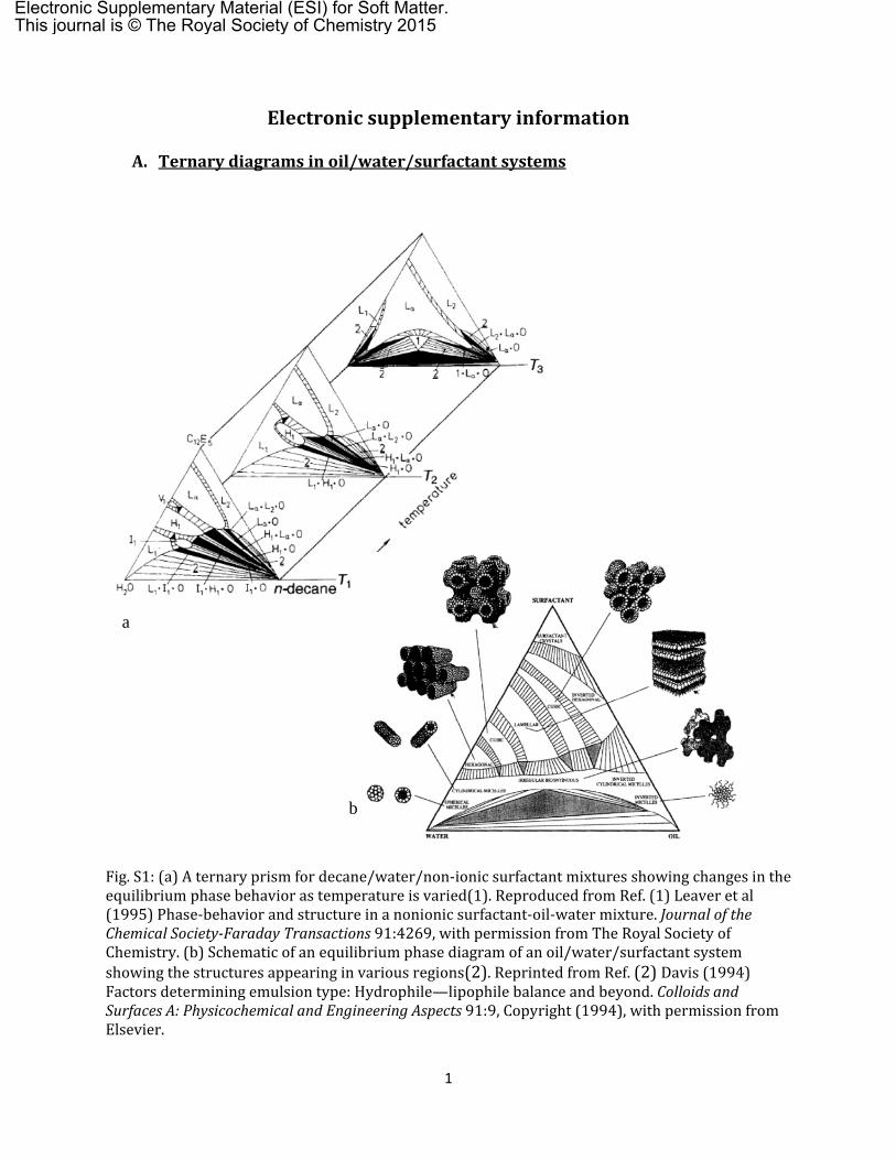
Fig.S2:Morphologiesinvariousregionsofthestateprismsforwater/air/particlemixtures.(a)pendularmorphology(3),(b)sphericalagglomerate;insetshowsopticalmicroscopyimageofthesurfacewithparticlesprotrudingoutside(Velankar,unpublished),(c)particulatesuspensionswithoutentrainedairbubbles(Velankar,unpublished).Theleftmostimageisapastyparticle‐watermixture;themiddleimageisaconcentratedsuspension,therightmostisdiluteinparticlesandtheparticleshavesedimented,(d)particle‐stabilizedfoam(4);insetshowsaconfocalimageofafoambubblewithparticlesattheinterface,(e)liquidmarblesandpowderedliquid(5).(a)ReprintedfromHerminghaus,AdvancesinPhysics,2005,54,221(3)bypermissionofthepublisher(Taylor&FrancisLtd).(d)ReproducedfromGonzenbachetal,Angew.Chem.,2006,45,3526(4)withpermissionfromWiley.(e)ReprintedbypermissionfromMacmillanPublishersLtd.fromBinksandMurakami,Nat.Mater.,2006,5,865(5);copyright(2006).
3
B. Experimentalresultsofstructuraltransitionsintheternaryprism
This section will cite examples of structural transitions in ternary liquid/fluid/particle systems as the
composition or wettability is changed. The literature on such ternary systems is vast, for example, with
over a thousand papers on “Pickering emulsions” and over two thousand on “filled polymer blends”. The
goal of this Supplement is to highlight exemplary cases from this literature in which structural transitions
are noted as the composition or wettability is changed systematically. Each figure in this section has three
parts: (1) a table with some details of the system, (2) images of the structure along a specific trajectory
within the triangular prism, and (3) a triangle or triangular prism illustrating the corresponding trajectory
as a red line. In some cases, the original articles also examined structural changes along other trajectories
in the composition diagram, and these are shown as dotted black lines.
The first section B.1 below concerns situations where the particles are fully-wetted by one phase, and in
these tables, the phase that fully-wets the particles is dubbed “B” whereas fluid “A” is regarded as non-
wetting. Section B.2 concerns situations where the particles are partially-wetted by both phase. Here the
phase that preferentially-wets the particles is generally dubbed B, although in some cases, the illustrated
trajectory traverses a range of wettabilities.
B.1 Fully‐wettablesystems
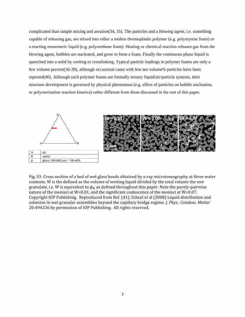
Fig. S3(6) and S4(7, 8) both correspond to adding increasing amounts of fully-wetting fluid to a
particulate system. Fig. S2 shows cross sections (obtained by x-ray tomography) of a bed of wet granular
particles with ~58 vol% particle loading, and air as the continuous phase. A small amount of water was
added, mixed by fluidization, and followed by a long rest time. During the rest time, the water is
presumed to have equilibrated throughout the sample. Fig. S3 shows that at low water content, the water
is present as pair-wise pendular bridges between the particles. With increasing water fraction, the menisci
grow and coalesce, and may eventually encapsulate some of the particles.
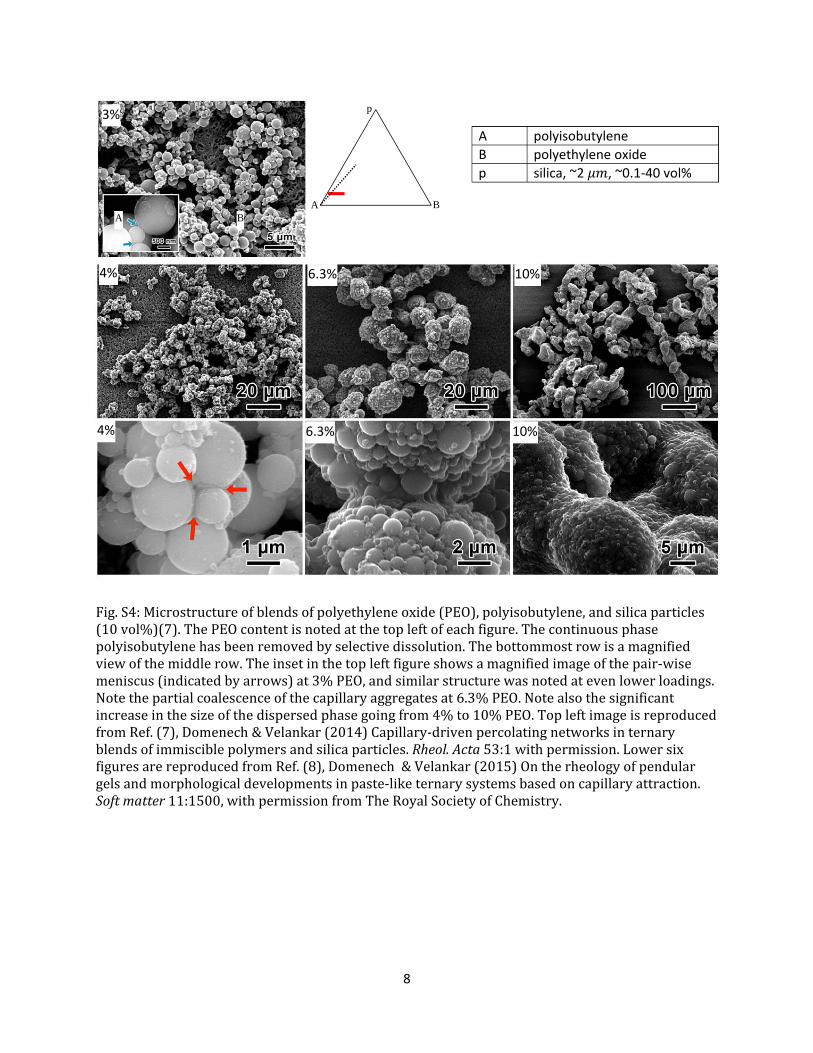
Fig. S4 shows mixtures of particles and two immiscible polymers prepared by melt blending. The particle
size is roughly 100-fold smaller, and the viscosity is at least 10 times higher, as compared to Fig. S4.
The particle loading is 10 vol%. Due the small particle size and high viscosity, the particles do not
sediment significantly prior to quenching the sample, and hence the structure obtained by ex situ electron
microscopy is well-representative of the structure immediately after mixing. Despite the difference in
particle size, fluid viscosity, and particle loading as compared to Fig. S3, the structures observed are
similar. Once again, a pendular structure is evident when the wetting fluid is dilute. With increasing
wetting fluid loading, menisci first coalesce into funicular clusters. Upon raising the wetting fluid content
4
even higher, (typically to 25-80% of the particle loading), the particles are completely engulfed into
capillary aggregates. Similar pendular menisci have been seen by confocal imaging in systems where the
two liquids are oil and water (Koos et al. personal communication). Pendular and funicular aggregates
appear even the preparation method is completely different, e.g. quenching a liquid-liquid mixture from a
single phase to a two-phase state in a particle bed(9), or allowing gravitational drainage through a packing
of particles(10, 11).
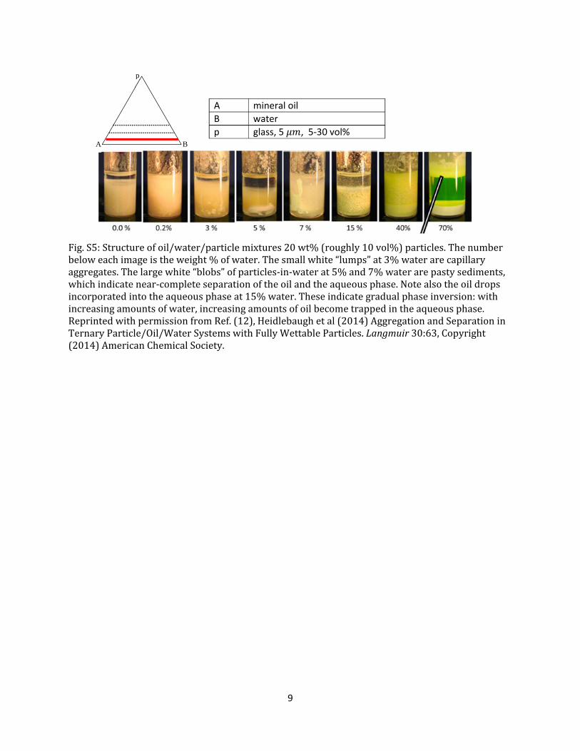
Fig. S5(12) shows the same pendular and capillary aggregate states in an oil/water/hydrophilic particles
system, but then also shows higher wetting fluid (water) content. In this case, the samples were prepared
by simply shaking the components in a vial. Pendular aggregates were reported at the lowest particle
loading by optical microscopy (not reproduced here). Upon increasing the wetting fluid loading, capillary
aggregates are visible as small compact lumps at the bottom of the vial. Upon increasing the water content
slightly beyond that needed for capillary aggregates, the mixture rapidly undergoes macroscopic phase
separation into an oil layer resting on a large “blob” of the particle-in-water aqueous phase. The same
sequence of transitions, from pendular aggregates to capillary aggregates, to macroscopic separation were
shown by Sirianni et al(13) in oil/water/hydrophobic particle systems and by Domenech and Velankar(12)
in polymeric systems. Liquid/air/particle systems also show the same sequence of transitions (discussed
below). As mentioned in the main article, industrial processes variously known as wet granulation,
spherical agglomeration, or oil agglomeration all rely on capillary aggregate formation, and substantial
literature in that context(14-19) shows the same sequence of transitions.
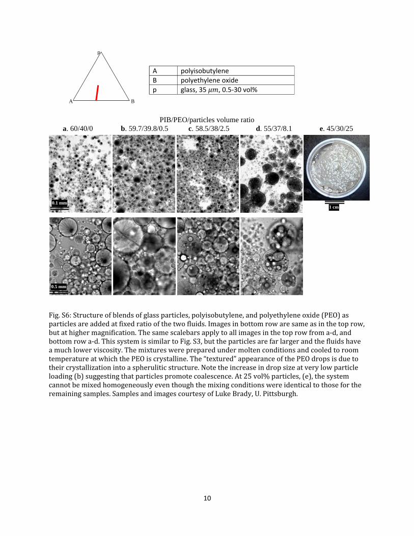
Fig. S6 shows the effect of adding particles while holding the fluid volume ratio fixed. This system is
similar to that in Fig. S4, except that the particles are an order of magnitude larger and the fluids are an
order of magnitude less viscous; accordingly gravitational effects are much stronger in Fig. S6. Yet,
similar to Fig. S4, since the drops can be frozen by cooling, the structure can be quenched in a fashion not
possible with oil/water systems. The particle-free system has the wetting fluid (which is in a minority) as
the dispersed phase. Addition of a small amount of particles is seen to increase the drop size, an effect
also seen previously in other systems(20-22). With further addition of particles, the system progresses
from a particles-in-drop structure to very poor mixing, i.e. macrophase separation. Thus, macroscopic
phase separation appears to be a common feature of ternary systems if the particle volume fraction is
comparable to the wetting fluid fraction. The reasons for this are discussed in the main text.
Upon further increase in the wetting fluid, phase inversion is expected so that B becomes the continuous
phase. Studies of the effect of fully-wetting particles on phase inversion are uncommon in the literature.
Fig. S5(12) illustrates an example of phase inversion in an oil/water/hydrophilic particle system as the
5
water:oil ratio is increased at fixed particle loading. Phase inversion was seen to proceed gradually where,
starting from the completely separated state, an increasing amount of the oil is incorporated into the
aqueous phase fluid until no free oil remained. It must be emphasized that in such low viscosity systems,
gravity rapidly induces sedimentation and then coalescence. Thus observations such as Fig. S5
correspond to post-mixing conditions. In polymeric systems with much higher viscosity, as mentioned
above, sedimentation is negligible, and hence the structure during mixing conditions can be quenched
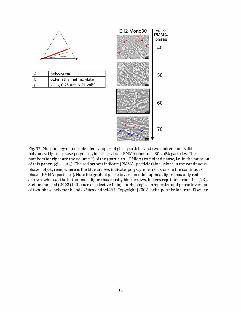
easily. Fig. S7 shows such an example(23). Here the particles were pre-dispersed into the fully-wetting
phase (polymethyl methacrylate), and then this combined phase was melt-blended with polystyrene at
various ratios. Similar to Fig. S5, in such a case as well, that phase inversion proceeds continuously: as
the volume of one phase increases, it entrains increasing amounts of the other in the form of drops. Some
of the morphologies in Fig. S7 appear bicontinuous, which is common in polymer systems. This
article(23) did not report on blends with highly mismatched fluid volume ratios, but we presume that if
either phase was in a small minority, it would form a more conventional droplet-matrix structure.
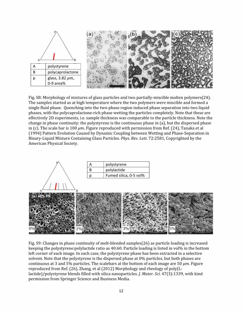
Fig. S8(24) shows that phase inversion can also be induced by increasing the particle loading at fixed
fluid volume ratio. The system is seen to move from a particles-in-drops structure to a drops-in-
suspension structure. This specific example was not realized by mixing, but instead by phase separation:
the two polymers were partially-miscible with a upper-critical solution temperature. The ternary mixtures
were first held at high temperature at which the two polymer liquids formed a single homogeneous phase.
Cooling into the two-phase region induced phase-separation. Another unusual aspect of this experiment is
that it is a 2D experiment: the sample thickness was comparable to a single particle diameter. Thus, Fig.
S8 is somewhat different from most of the other examples in this paper. Nevertheless, recent experiments
in our lab(25) confirm the main point of Fig. S8 that phase inversion can be induced by raising particle
loading. This is not surprising: as explained in Section 4.2 in the main article, the particles and the wetting
fluid form a combined phase. With increasing particle loading, this combined phase increases its volume
fraction and tends to become the continuous phase.
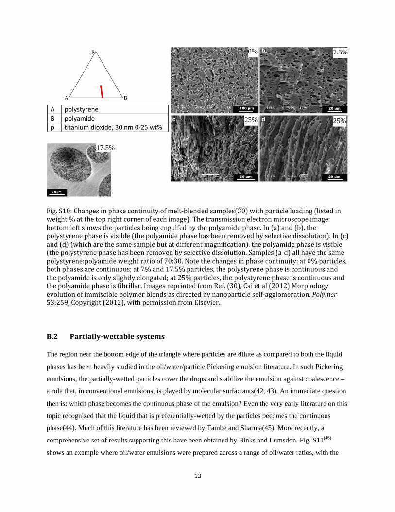
In melt-blended polymeric systems, changes in phase continuity often include bicontinuous or fibrillar
structures. Fig. S9(26) shows an example of adding various amounts of fumed silica to blends of
polystyrene and polylactide (the latter is fully-wetting towards the particles). The particle-free blend has a
droplet-matrix structure with the non-wetting phase (which is in a minority) becoming the dispersed
phase. Addition of 5 wt% fumed silica induces a transformation into into a bicontinuous structure. Similar
results were shown by Lee et al.(27) Sometimes addition of particles may convert a spherical dispersed
phase into a highly irregular dispersed phase without reaching full continuity(28, 29). Another example
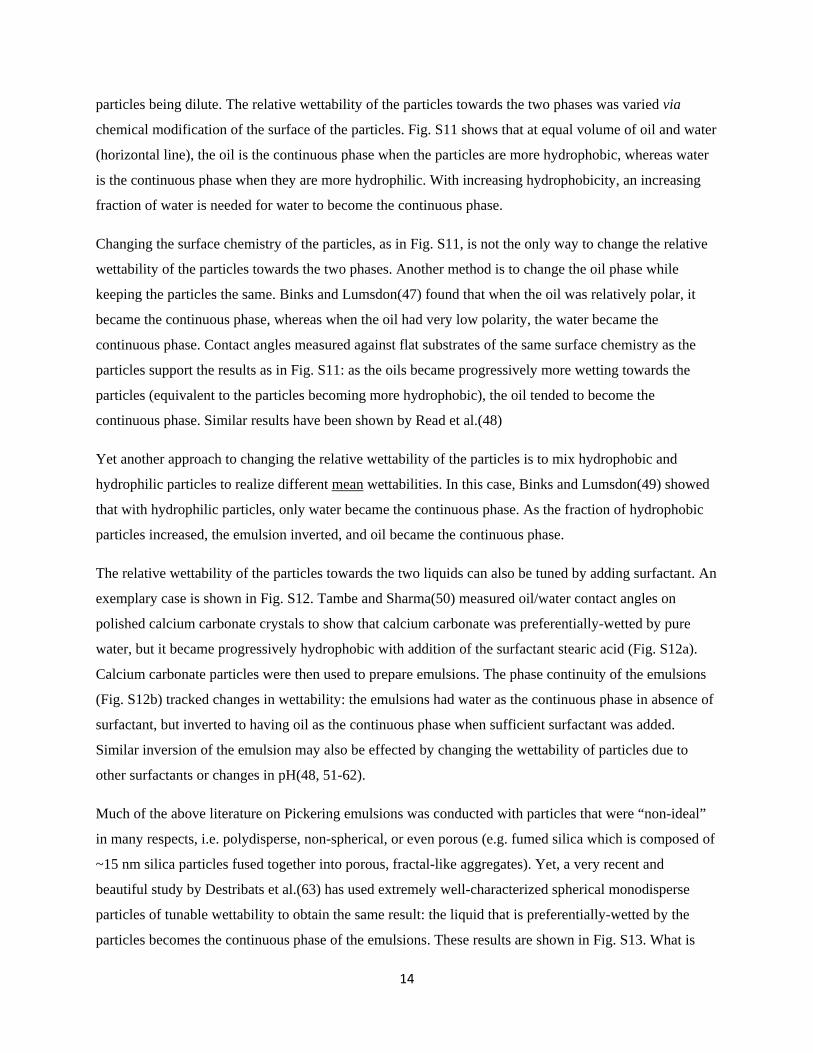
from molten polymeric systems is provided by Fig. S10(30). Unlike Fig. S9, the non-wetting phase is in a
6
majority, and the initial the particle-free blend is bicontinuous (Fig. S10a). Addition of particles destroys
the bicontinuity. At low particle loadings, the combined (particle+wetting fluid) phase takes the shape of
rounded drops. At higher particle loadings, the combined phase forms elongated fibrils.
We briefly now comment on the similarities and differences when one of the fluids is air. One significant
difference is that in a gravitational environment, the overall composition cannot be controlled exactly:
only the liquid:particle ratio can be controlled. The materials and the mixing method then determine how
much air gets incorporated into the structure. Nevertheless, at low liquid loadings, pendular structures are
seen (Fig. S2a & Fig. S3), and these transition into funicular structures as the liquid loading increases(31).
With further increase in wetting fluid, capillary aggregates are formed (Fig. S2b). Formation of capillary
aggregates is the basis of wet granulation, a process used to increase the size of fine powders(15, 32).
This process is analogous to the spherical agglomeration process mentioned above, except that wet
granulation involves liquid/air/particle mixtures. The process consists of spraying a wetting liquid (in this
context called a binder) onto a bed of particles, and mixing to induce the growth of strong and compact
capillary aggregates. Finally, analogous to the liquid/liquid/particle cases above, liquid/air/particle
mixtures also undergo macroscopic phase separation when the liquid volume is roughly equal to the
particle volume. Indeed, in the context of wet granulation processes, it is well-recognized that excess
binder can create a pasty liquid/particle mixture (leftmost image if Fig. 2c) which does not form compact
aggregates(33). In a formal sense, this may be regarded as macroscopic separation of the air from the
aqueous phase. Incidentally, a kitchen table experiment can readily demonstrate this entire sequence of
transitions: shaking starch granules with a small quantity of water first gives a “moldable” material
analogous to wet sand. Upon increasing the water content, capillary aggregates such as shown in Fig. S2b
are formed. Adding even slightly more liquid gives a pasty particle-water mixture corresponding to
macroscopic separation, followed by increasingly dilute suspensions in which particles may settle(Fig.
S2c).
In summary, at small loadings of wetting fluid liquid/air/particle mixtures are completely analogous to
liquid/liquid/particle mixtures, and show the same sequence of pendular-funicular-capillary-separated
states. With further increase in wetting liquid however, the analogy breaks down: there is no analog to
phase inversion when one of the fluids is air, at least not when particles are completely wetted by the
liquid. Instead, when the liquid loading increases to a sufficiently high value, one usually obtains a
suspension of particles in the liquid, rather than a phase-inverted foam. While some air may be entrained
during mixing conditions, the bubbles rise rapidly under quiescent conditions, and the air is excluded
completely from the liquid phase. A notable exception to this, polymer foams with filler particles in the
polymer phase, was mentioned in the main text. Such foams are prepared by methods significantly more
7
complicated than simple mixing and aeration(34, 35). The particles and a blowing agent, i.e. something
capable of releasing gas, are mixed into either a molten thermoplastic polymer (e.g. polystyrene foam) or
a reacting monomeric liquid (e.g. polyurethane foam). Heating or chemical reaction releases gas from the
blowing agent, bubbles are nucleated, and grow to form a foam. Finally the continuous phase liquid is
quenched into a solid by cooling or crosslinking. Typical particle loadings in polymer foams are only a
few volume percent(36-39), although occasional cases with few ten volume% particles have been
reported(40). Although such polymer foams are formally ternary liquid/air/particle systems, their
structure development is governed by physical phenomena (e.g. effect of particles on bubble nucleation,
or polymerization reaction kinetics) rather different from those discussed in the rest of this paper.
Fig.S3:Crosssectionofabedofwetglassbeadsobtainedbyx‐raymicrotomographyatthreewatercontents.Wisthedefinedasthevolumeofwettingliquiddividedbythetotalvolumethewetgranulate,i.e.Wisequivalentto asdefinedthroughoutthispaper.Notethepurely‐pairwisenatureofthemenisciatW=0.01,andthesignificantcoalescenceofthemenisciatW=0.07.CopyrightIOPPublishing.ReproducedfromRef.(41),Scheeletal(2008)Liquiddistributionandcohesioninwetgranularassembliesbeyondthecapillarybridgeregime.J.Phys.:Condens.Matter20:494236bypermissionofIOPPublishing.Allrightsreserved.
A air
B water
p glass, 140‐600 , ~ 58 vol%
A B
p
8
Fig.S4:Microstructureofblendsofpolyethyleneoxide(PEO),polyisobutylene,andsilicaparticles(10vol%)(7).ThePEOcontentisnotedatthetopleftofeachfigure.Thecontinuousphasepolyisobutylenehasbeenremovedbyselectivedissolution.Thebottommostrowisamagnifiedviewofthemiddlerow.Theinsetinthetopleftfigureshowsamagnifiedimageofthepair‐wisemeniscus(indicatedbyarrows)at3%PEO,andsimilarstructurewasnotedatevenlowerloadings.Notethepartialcoalescenceofthecapillaryaggregatesat6.3%PEO.Notealsothesignificantincreaseinthesizeofthedispersedphasegoingfrom4%to10%PEO.TopleftimageisreproducedfromRef.(7),Domenech&Velankar(2014)Capillary‐drivenpercolatingnetworksinternaryblendsofimmisciblepolymersandsilicaparticles.Rheol.Acta53:1withpermission.LowersixfiguresarereproducedfromRef.(8),Domenech&Velankar(2015)Ontherheologyofpendulargelsandmorphologicaldevelopmentsinpaste‐liketernarysystemsbasedoncapillaryattraction.Softmatter11:1500,withpermissionfromTheRoyalSocietyofChemistry.
A polyisobutylene
B polyethylene oxide
p silica, ~2 , ~0.1‐40 vol%
3%
4% 6.3% 10%
4% 6.3% 10%
A B
A B
p
9
Fig.S5:Structureofoil/water/particlemixtures20wt%(roughly10vol%)particles.Thenumberbeloweachimageistheweight%ofwater.Thesmallwhite“lumps”at3%waterarecapillaryaggregates.Thelargewhite“blobs”ofparticles‐in‐waterat5%and7%waterarepastysediments,whichindicatenear‐completeseparationoftheoilandtheaqueousphase.Notealsotheoildropsincorporatedintotheaqueousphaseat15%water.Theseindicategradualphaseinversion:withincreasingamountsofwater,increasingamountsofoilbecometrappedintheaqueousphase.ReprintedwithpermissionfromRef.(12),Heidlebaughetal(2014)AggregationandSeparationinTernaryParticle/Oil/WaterSystemswithFullyWettableParticles.Langmuir30:63,Copyright(2014)AmericanChemicalSociety.
A mineral oil
B water
p glass, 5 , 5‐30 vol% A B
p
10
Fig.S6:Structureofblendsofglassparticles,polyisobutylene,andpolyethyleneoxide(PEO)asparticlesareaddedatfixedratioofthetwofluids.Imagesinbottomrowaresameasinthetoprow,butathighermagnification.Thesamescalebarsapplytoallimagesinthetoprowfroma‐d,andbottomrowa‐d.ThissystemissimilartoFig.S3,buttheparticlesarefarlargerandthefluidshaveamuchlowerviscosity.ThemixtureswerepreparedundermoltenconditionsandcooledtoroomtemperatureatwhichthePEOiscrystalline.The“textured”appearanceofthePEOdropsisduetotheircrystallizationintoaspheruliticstructure.Notetheincreaseindropsizeatverylowparticleloading(b)suggestingthatparticlespromotecoalescence.At25vol%particles,(e),thesystemcannotbemixedhomogeneouslyeventhoughthemixingconditionswereidenticaltothosefortheremainingsamples.SamplesandimagescourtesyofLukeBrady,U.Pittsburgh.
A polyisobutylene
B polyethylene oxide
p glass, 35 , 0.5‐30 vol%
PIB/PEO/particles volume ratio a. 60/40/0 b. 59.7/39.8/0.5 c. 58.5/38/2.5 d. 55/37/8.1 e. 45/30/25
A B
p
0.1 mm
0.5 mm
1 cm
11
Fig.S7:Morphologyofmelt‐blendedsamplesofglassparticlesandtwomoltenimmisciblepolymers.Lighterphasepolymethylmethacrylate(PMMA)contains30vol%particles.Thenumbersfarrightarethevolume%ofthe(particles+PMMA)combinedphase,i.e.inthenotationofthispaper, .Theredarrowsindicate(PMMA+particles)inclusionsinthecontinuousphasepolystyrene,whereasthebluearrowsindicatepolystyreneinclusionsinthecontinuousphase(PMMA+particles).Notethegradualphaseinversion:thetopmostfigurehasonlyredarrows,whereasthebottommostfigurehasmostlybluearrows.ImagesreprintedfromRef.(23),Steinmannetal(2002)Influenceofselectivefillingonrheologicalpropertiesandphaseinversionoftwo‐phasepolymerblends.Polymer43:4467,Copyright(2002),withpermissionfromElsevier.
A polystyrene
B polymethylmethacrylate
p glass, 0.25 , 3‐21 vol%
A B
p
12
Fig.S8:Morphologyofmixturesofglassparticlesandtwopartially‐misciblemoltenpolymers(24).Thesamplesstartedasathightemperaturewherethetwopolymersweremiscibleandformedasinglefluidphase.Quenchingintothetwo‐phaseregioninducedphaseseparationintotwoliquidphases,withthepolycaprolactone‐richphasewettingtheparticlescompletely.Notethattheseareeffectively2Dexperiments,i.e.samplethicknesswascomparabletotheparticlethickness.Notethechangeinphasecontinuity:thepolystyreneisthecontinuousphasein(a),butthedispersedphasein(c).Thescalebaris100 .FigurereproducedwithpermissionfromRef.(24),Tanakaetal(1994)PatternEvolutionCausedbyDynamicCouplingbetweenWettingandPhase‐SeparationinBinary‐LiquidMixtureContainingGlassParticles.Phys.Rev.Lett.72:2581,CopyrightedbytheAmericanPhysicalSociety.
Fig.S9:Changesinphasecontinuityofmelt‐blendedsamples(26)asparticleloadingisincreasedkeepingthepolystyrene:polylactideratioas40:60.Particleloadingislistedinvol%inthebottomleftcornerofeachimage.Ineachcase,thepolystyrenephasehasbeenextractedinaselectivesolvent.Notethatthepolystyreneisthedispersedphaseat0%particles,butbothphasesarecontinuousat3and5%particles.Thescalebarsatthebottomofeachimageare50 .FigurereproducedfromRef.(26),Zhang,etal(2012)Morphologyandrheologyofpoly(L‐lactide)/polystyreneblendsfilledwithsilicananoparticles.J.Mater.Sci.47(3):1339,withkindpermissionfromSpringerScienceandBusinessMedia.
A polystyrene
B polycaprolactone
p glass, 3.82 , 0‐9 area%
A B
p
A polystyrene
B polylactide
p Fumed silica, 0‐5 vol%
0% 1% 3% 5%
A B
p
13
Fig.S10:Changesinphasecontinuityofmelt‐blendedsamples(30)withparticleloading(listedinweight%atthetoprightcornerofeachimage).Thetransmissionelectronmicroscopeimagebottomleftshowstheparticlesbeingengulfedbythepolyamidephase.In(a)and(b),thepolystyrenephaseisvisible(thepolyamidephasehasbeenremovedbyselectivedissolution).In(c)and(d)(whicharethesamesamplebutatdifferentmagnification),thepolyamidephaseisvisible(thepolystyrenephasehasbeenremovedbyselectivedissolution.Samples(a‐d)allhavethesamepolystyrene:polyamideweightratioof70:30.Notethechangesinphasecontinuity:at0%particles,bothphasesarecontinuous;at7%and17.5%particles,thepolystyrenephaseiscontinuousandthepolyamideisonlyslightlyelongated;at25%particles,thepolystyrenephaseiscontinuousandthepolyamidephaseisfibrillar.ImagesreprintedfromRef.(30),Caietal(2012)Morphologyevolutionofimmisciblepolymerblendsasdirectedbynanoparticleself‐agglomeration.Polymer53:259,Copyright(2012),withpermissionfromElsevier.
B.2 Partially‐wettablesystems
The region near the bottom edge of the triangle where particles are dilute as compared to both the liquid
phases has been heavily studied in the oil/water/particle Pickering emulsion literature. In such Pickering
emulsions, the partially-wetted particles cover the drops and stabilize the emulsion against coalescence –
a role that, in conventional emulsions, is played by molecular surfactants(42, 43). An immediate question
then is: which phase becomes the continuous phase of the emulsion? Even the very early literature on this
topic recognized that the liquid that is preferentially-wetted by the particles becomes the continuous
phase(44). Much of this literature has been reviewed by Tambe and Sharma(45). More recently, a
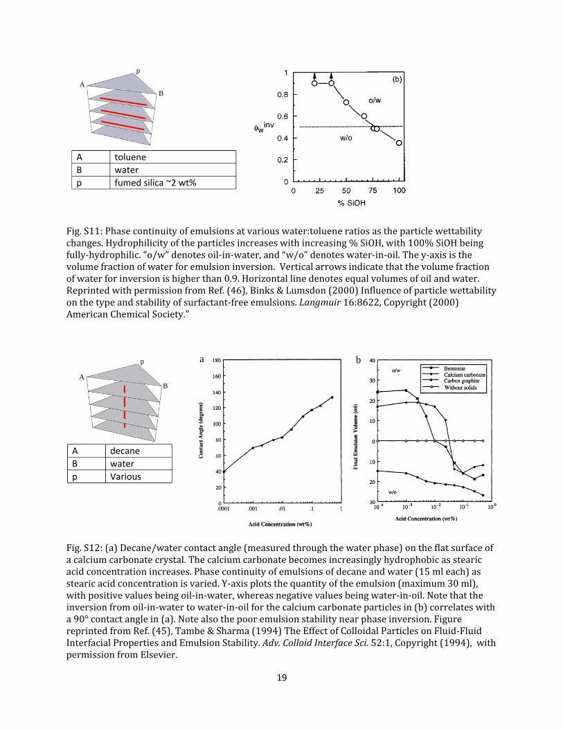
comprehensive set of results supporting this have been obtained by Binks and Lumsdon. Fig. S11(46)
shows an example where oil/water emulsions were prepared across a range of oil/water ratios, with the
A polystyrene
B polyamide
p titanium dioxide, 30 nm 0‐25 wt%
0% 7.5%
25% 25%
17.5%
A B
p
14
particles being dilute. The relative wettability of the particles towards the two phases was varied via
chemical modification of the surface of the particles. Fig. S11 shows that at equal volume of oil and water
(horizontal line), the oil is the continuous phase when the particles are more hydrophobic, whereas water
is the continuous phase when they are more hydrophilic. With increasing hydrophobicity, an increasing
fraction of water is needed for water to become the continuous phase.
Changing the surface chemistry of the particles, as in Fig. S11, is not the only way to change the relative
wettability of the particles towards the two phases. Another method is to change the oil phase while
keeping the particles the same. Binks and Lumsdon(47) found that when the oil was relatively polar, it
became the continuous phase, whereas when the oil had very low polarity, the water became the
continuous phase. Contact angles measured against flat substrates of the same surface chemistry as the
particles support the results as in Fig. S11: as the oils became progressively more wetting towards the
particles (equivalent to the particles becoming more hydrophobic), the oil tended to become the
continuous phase. Similar results have been shown by Read et al.(48)
Yet another approach to changing the relative wettability of the particles is to mix hydrophobic and
hydrophilic particles to realize different mean wettabilities. In this case, Binks and Lumsdon(49) showed
that with hydrophilic particles, only water became the continuous phase. As the fraction of hydrophobic
particles increased, the emulsion inverted, and oil became the continuous phase.
The relative wettability of the particles towards the two liquids can also be tuned by adding surfactant. An
exemplary case is shown in Fig. S12. Tambe and Sharma(50) measured oil/water contact angles on
polished calcium carbonate crystals to show that calcium carbonate was preferentially-wetted by pure
water, but it became progressively hydrophobic with addition of the surfactant stearic acid (Fig. S12a).
Calcium carbonate particles were then used to prepare emulsions. The phase continuity of the emulsions
(Fig. S12b) tracked changes in wettability: the emulsions had water as the continuous phase in absence of
surfactant, but inverted to having oil as the continuous phase when sufficient surfactant was added.
Similar inversion of the emulsion may also be effected by changing the wettability of particles due to
other surfactants or changes in pH(48, 51-62).
Much of the above literature on Pickering emulsions was conducted with particles that were “non-ideal”
in many respects, i.e. polydisperse, non-spherical, or even porous (e.g. fumed silica which is composed of
~15 nm silica particles fused together into porous, fractal-like aggregates). Yet, a very recent and
beautiful study by Destribats et al.(63) has used extremely well-characterized spherical monodisperse
particles of tunable wettability to obtain the same result: the liquid that is preferentially-wetted by the
particles becomes the continuous phase of the emulsions. These results are shown in Fig. S13. What is
15
most noteworthy about this research is that the contact angles on the exact same system were measured by
electron microscopy; to our knowledge, this is the only article that conclusively shows that phase
inversion occurs when the contact angle is near 90°. Finally, Fig. S14(64) shows emulsions in the same
region of composition space (dilute particles) but prepared by a completely different method. In this case,
a homogeneous single-phase liquid was quenched into the two-phase region and allowed to phase-
separate with no applied mixing flow. Despite the different preparation method, Fig. S14 yields the same
result: shows that the continuous phase is the one that preferentially-wets the particles. Incidentally, Fig.
S14 shows a bicontinuous structure to be discussed later. In summary, this result appears very consistent:
the “favorable” emulsion is the one in which the preferentially-wetting fluid is the continuous phase, i.e.
the particles prefer to protrude out of the drops rather than into the drops. The “unfavorable” emulsion can
be prepared of course, for instance, Fig. S11 showed that by simply diluting the preferentially-wetting
liquid sufficiently, it can be forced to become the dispersed phase. Such inversion induced by changing
the relative volume of the phases is called catastrophic inversion.
The above discussion immediately raises the question of what happens if neither phase is preferentially-
wetting, i.e. if the particles are equally-wetted by both phases. Perhaps the research that addresses this
most directly is Destribats et al.(63): since they actually measured contact angles directly, conditions of
equal wettability could be determined unambiguously. This article reported that a 90° contact angle gave
poor emulsion stability (Fig. S13b), i.e. neither oil-in-water nor water-in-oil emulsions were stable when
particles are equally-wetted by both phases. We may also look into studies of transitional inversion, i.e.
phase inversion occurring at fixed volume ratio of the two liquids due to changes in temperature, pH, or
addition of surfactant (e.g. Fig. S12). Most articles on transitional inversion of Pickering emulsions did
not measure contact angles at all. In some cases(50, 65), contact angles were measured on a similar
system, e.g. in Fig. S12 contact angles were measured on a flat surface of the same material as the
particles. Yet, it is plausible that transitional phase inversion roughly corresponds to equal wetting by
both phases, and therefore, emulsion stability near transitional phase inversion may be also be indicative
of behavior near equal wettability. Such studies offer conflicting evidence. For instance, Fig. S12 shows
that at intermediate wettability in the vicinity of phase inversion, the emulsion is unstable under quiescent
conditions, and readily separates into two phases due to coalescence. Other papers have also reported
unstable emulsions near transitional inversion when wettability was changed by varying the pH, or salt
content(45) or surfactant(66). A much older article by Briggs(44) reported that hydrophilic and
hydrophobic particles (which individually stabilized oil-in-water and water-in-oil emulsions respectively),
when mixed, gave highly unstable emulsions. All these examples support the idea that particles with
equal wettability towards both phases gives unstable emulsions. On the other hand, several papers reach
16
the exact opposite conclusion: they show that Pickering emulsions are highly stable near transitional
inversion(48, 51-55, 58, 59, 62). These include a diversity of particle types: fumed silica, colloidal silica,
latex, or clay. Finally formation of double emulsions i.e. emulsions with a drop-within-drop structure(55,
64, 67-69) has also been noted. In summary, the question of emulsion stability with equally-wettable
particles remains unsettled; it is possible that the conflicting results may be due to factors other than
particle wettability, e.g. the rheological characteristics of the interface.
We now turn to morphologies that are more unusual than conventional droplet-matrix structures. In the
case when the contact angle of the particles measured through the continuous phase is small (but still far
from zero), an unusual morphology dubbed a bridged Pickering emulsion gel has been noted in both
oil/water (Fig. S15)(70) as well as polymeric systems (Fig. S16)(21). In this case, a monolayer of
particles is sandwiched between two drops, holding a stable film of the preferentially-wetting fluid
separating the drops(71-75). Fig. S15 corresponds to a small-molecule system with a relatively high
loading (8-18 vol%) particles, and a high surface coverage is reached. In this case, the drops deform into
polyhedral shapes resembling foams. Fig. S16 corresponds to a polymeric system with much lower (~1
vol% or lower) particle loadings. At the lowest particle loadings, the surface coverage of the particles is
not adequate to cover the entire surface of the particles. In this case, the polyhedral shapes do not appear;
instead the particles partition into the contact region between the drops, leaving much of the drop surfaces
bare. Similar results have been shown by Horozov(21, 74). We emphasize that Fig. S15 and S16C&D and
elsewhere(71-75), the drops are flattened against each other even though they are not crowded, e.g. in Fig.
S15a, drop volume fraction is less than 0.2. Instead the drops are flattened against each other because the
bridged particles constitute an attractive force between the drops which can overcome their capillary
pressure. In both cases, such mixtures tend to show gel-like rheology since the drops are glued together.
We emphasize that while bridging requires the contact angle to be far from 90°, it must also be
sufficiently far from zero. If the contact angle is too close to zero, then one reverts back to the fully-
wetting situation discussed in the earlier part of this Supplementary Material.
Next we turn to the special case of bicontinuous structures. Surfactant-free small molecule mixtures do
not show bicontinuous structures readily. However, when a homogeneous binary mixture (without
particles) is quenched into the two phase region, phase separation occurs via spinodal decomposition, and
if the phase volume ratios are roughly equal, bicontinuous morphologies results. These usually coarsen
and often break into dispersed phase morphologies. However addition of particles that are equally-wetted
by both phases can arrest phase separation to give a bijel(76). A bijel was already evident in Fig. S14b. A
more detailed example is shown in Fig. S17. Fig. S17a examines mixtures in which the two phases had
nearly equal volumes. While structural arrest (as evidenced by non-spherical interfacial shapes) can
17
happen at very low particle loading, at particle loadings exceeding 1.6%, true bicontinuity can be reached.
Fig. S17b shows fixed particle loadings across a range of fluid volume ratios and emphasizes emphasizes
that bijels appear only the two fluids have nearly equal volumes(77). Similar bijels have been realized by
spinodal decomposition in other systems including polymers(78-81).
In contrast to small-molecule systems, blends of immiscible homopolymers even in the absence of added
particles, show bicontinuous structures near phase inversion(82). Bicontinuity may be flanked on both
sides by highly elongated or fibrillar structures which become increasingly interconnected as true
bicontinuity is approached. In many instances, interfacially-adsorbed particles are recognized to stabilize
bicontinuous(83-86) or other highly non-spherical morphologies against coarsening(21, 87, 88). However
when one considers not merely quiescent stabilization against morphological coarsening, but the
formation of bicontinous morphologies or of highly elongated structures, the effects of interfacial
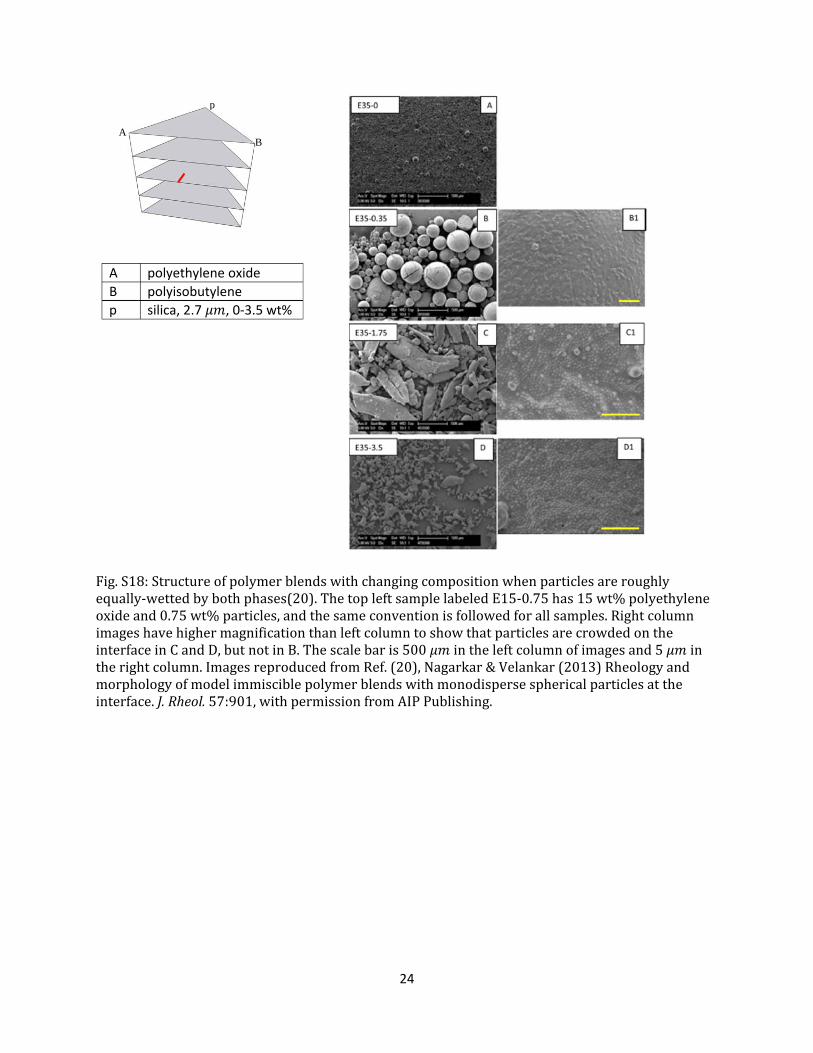
particles appear to be more complex. For instance, Fig. S18(20) illustrates an example in which the
particle-free two-phase morphology consists of spherical drops of one polymer dispersed in another.
Addition of particles first induces the formation of highly elongated structures that are interfacially-
jammed. At higher particle loadings however, the dispersed phase reverts to less elongated (although still
interfacially-jammed) shapes. Similar transition to highly elongated structures has also been noted by
Tong et al.(88) At least one publication(86) has noted that particles increase the range of compositions
over which bicontinuity is realized.
All the discussion in this section thus far was restricted to relatively low particle loadings, typically under
10 vol%, and often under 2 vol%. The literature on the behavior at higher particle loadings is sparse.
Koos et al(89) have examined the rheological behavior of three-component systems with partially-
wettable particles across a wide range of fluid volume ratios at particle loadings up to 30 vol%, however
structural characterization was reported only when the one of the fluids was very dilute. One remarkable
result from this research is that even drops that do not preferentially-wet the particles can glue together
the particles into a space-spanning network illustrated in Fig. 3g in the main text. The building blocks of
this network are believed to be clusters composed of several particles held together by a single drop(90).
In a sense, the cluster resembles a typical particle-coated drop from a Pickering emulsion except that the
drops are comparable in size to the particles, i.e. Fig. 3g and h differ only in the size of drops relative to
the particles. In the same sense, the network of clusters is analogous to a particle-bridged Pickering
emulsion gel, and both show gel-like rheology.
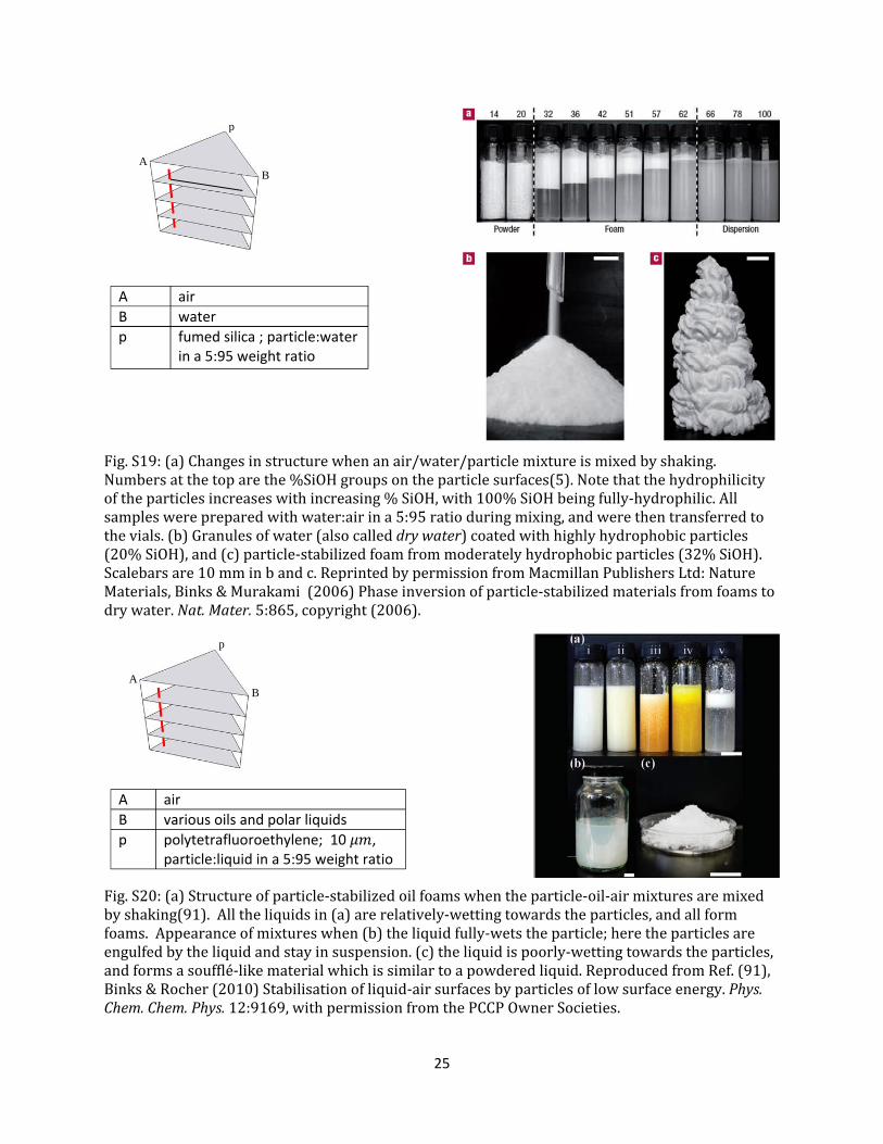
Finally we turn to the special case when one of the fluids is air. Fig. S19 shows the structure of
air/water/hydrophobic particle systems mixed by shaking all components together(5). A remarkable
18
phenomenon of transitional phase inversion is observed as the wettability of particles is changed: highly
hydrophilic particles remain dispersed in water (with air being excluded completely), somewhat-
hydrophobic particles stabilize foams (with air as the dispersed phase), whereas highly hydrophobic
particles stabilize liquid marbles (with air as the continuous phase). This figure is analogous to Fig. S11,
but with the oil replaced by air. Similar to oil/water systems, in the air/water system too, transitional
inversion can be induced by addition of surfactant or by changing pH, or by changing the polarity of the
oil(91-93). This last example is illustrated in Fig. S20 which shows liquid/air/particle mixtures realized
using the same particles, but a variety of non-aqueous liquids(91). The various liquids have different
wettability towards the particles; liquids with relatively good wettability towards the particles form foams
(Fig S20a), but the foam stability becomes poorer as the wettability becomes poorer. Once the liquid
becomes sufficiently poorly-wetting towards the particles, inversion into a powdered liquid happens (Fig.
S20c), which is transitional inversion. Catastrophic inversion can also be induced by changing the
air/water ratio (91, 94), which is also analogous to oil/water systems.
Particle-stabilized dry liquids or liquid marbles have been reported in a variety of other systems(4, 95-97),
and many more articles can be found in recent reviews(98, 99). Numerous particle-stabilized foams have
also been reported(94, 100-105), including with molten plastics(106, 107). In summary, liquid/air/particle
mixtures behave similar to liquid/liquid/particle systems with the exception that bicontinuous
morphologies do not appear when one fluid is air.
19
Fig.S11:Phasecontinuityofemulsionsatvariouswater:tolueneratiosastheparticlewettabilitychanges.Hydrophilicityoftheparticlesincreaseswithincreasing%SiOH,with100%SiOHbeingfully‐hydrophilic.“o/w”denotesoil‐in‐water,and“w/o”denoteswater‐in‐oil.They‐axisisthevolumefractionofwaterforemulsioninversion.Verticalarrowsindicatethatthevolumefractionofwaterforinversionishigherthan0.9.Horizontallinedenotesequalvolumesofoilandwater.ReprintedwithpermissionfromRef.(46),Binks&Lumsdon(2000)Influenceofparticlewettabilityonthetypeandstabilityofsurfactant‐freeemulsions.Langmuir16:8622,Copyright(2000)AmericanChemicalSociety."
Fig.S12:(a)Decane/watercontactangle(measuredthroughthewaterphase)ontheflatsurfaceofacalciumcarbonatecrystal.Thecalciumcarbonatebecomesincreasinglyhydrophobicasstearicacidconcentrationincreases.Phasecontinuityofemulsionsofdecaneandwater(15mleach)asstearicacidconcentrationisvaried.Y‐axisplotsthequantityoftheemulsion(maximum30ml),withpositivevaluesbeingoil‐in‐water,whereasnegativevaluesbeingwater‐in‐oil.Notethattheinversionfromoil‐in‐watertowater‐in‐oilforthecalciumcarbonateparticlesin(b)correlateswitha90°contactanglein(a).Notealsothepooremulsionstabilitynearphaseinversion.FigurereprintedfromRef.(45),Tambe&Sharma(1994)TheEffectofColloidalParticlesonFluid‐FluidInterfacialPropertiesandEmulsionStability.Adv.ColloidInterfaceSci.52:1,Copyright(1994),withpermissionfromElsevier.
A toluene
B water
p fumed silica ~2 wt%
A B
p
A decane
B water
p Various
a b
A B
p
20
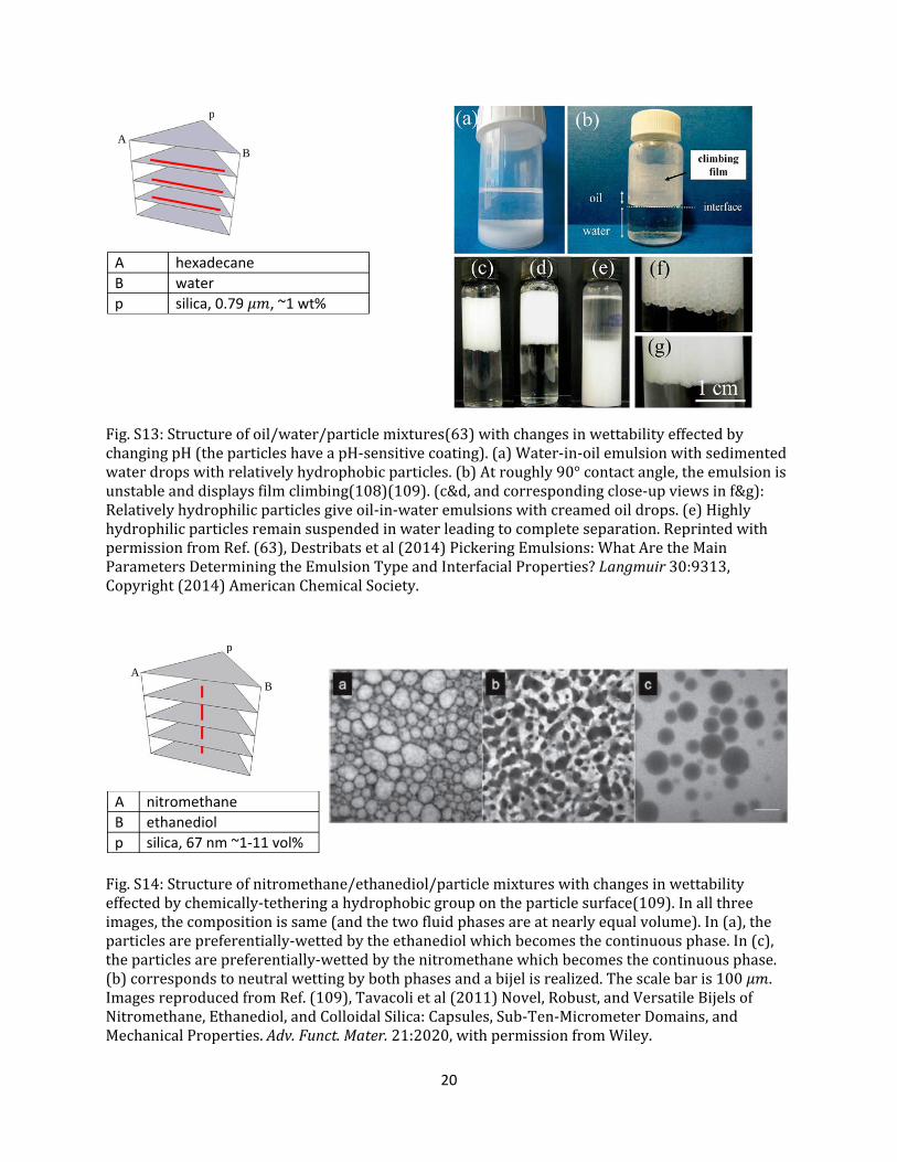
Fig.S13:Structureofoil/water/particlemixtures(63)withchangesinwettabilityeffectedbychangingpH(theparticleshaveapH‐sensitivecoating).(a)Water‐in‐oilemulsionwithsedimentedwaterdropswithrelativelyhydrophobicparticles.(b)Atroughly90°contactangle,theemulsionisunstableanddisplaysfilmclimbing(108)(109).(c&d,andcorrespondingclose‐upviewsinf&g):Relativelyhydrophilicparticlesgiveoil‐in‐wateremulsionswithcreamedoildrops.(e)Highlyhydrophilicparticlesremainsuspendedinwaterleadingtocompleteseparation.ReprintedwithpermissionfromRef.(63),Destribatsetal(2014)PickeringEmulsions:WhatAretheMainParametersDeterminingtheEmulsionTypeandInterfacialProperties?Langmuir30:9313,Copyright(2014)AmericanChemicalSociety.
Fig.S14:Structureofnitromethane/ethanediol/particlemixtureswithchangesinwettabilityeffectedbychemically‐tetheringahydrophobicgroupontheparticlesurface(109).Inallthreeimages,thecompositionissame(andthetwofluidphasesareatnearlyequalvolume).In(a),theparticlesarepreferentially‐wettedbytheethanediolwhichbecomesthecontinuousphase.In(c),theparticlesarepreferentially‐wettedbythenitromethanewhichbecomesthecontinuousphase.(b)correspondstoneutralwettingbybothphasesandabijelisrealized.Thescalebaris100 .ImagesreproducedfromRef.(109),Tavacolietal(2011)Novel,Robust,andVersatileBijelsofNitromethane,Ethanediol,andColloidalSilica:Capsules,Sub‐Ten‐MicrometerDomains,andMechanicalProperties.Adv.Funct.Mater.21:2020,withpermissionfromWiley.
A hexadecane
B water
p silica, 0.79 , ~1 wt%
AB
p
A nitromethane
B ethanediol
p silica, 67 nm ~1‐11 vol%
AB
p
21
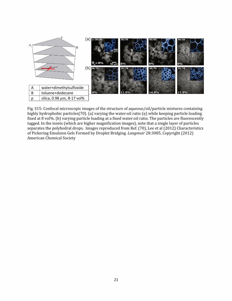
Fig.S15:Confocalmicroscopicimagesofthestructureofaqueous/oil/particlemixturescontaininghighlyhydrophobicparticles(70).(a)varyingthewater:oilratio( )whilekeepingparticleloadingfixedat8vol%.(b)varyingparticleloadingatafixedwater:oilratio.Theparticlesarefluorescentlytagged.Intheinsets(whicharehighermagnificationimages),notethatasinglelayerofparticlesseparatesthepolyhedraldrops.ImagesreproducedfromRef.(70),Leeetal(2012)CharacteristicsofPickeringEmulsionGelsFormedbyDropletBridging.Langmuir28:3085,Copyright(2012)AmericanChemicalSociety
A water+dimethylsulfoxide
B toluene+dodecane
p silica, 0.98 , 8‐17 vol%
AB
p
22
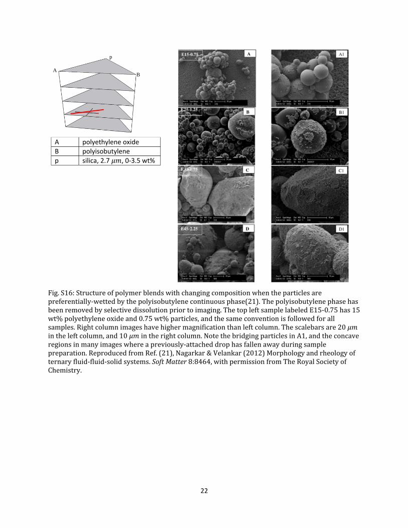
Fig.S16:Structureofpolymerblendswithchangingcompositionwhentheparticlesarepreferentially‐wettedbythepolyisobutylenecontinuousphase(21).Thepolyisobutylenephasehasbeenremovedbyselectivedissolutionpriortoimaging.ThetopleftsamplelabeledE15‐0.75has15wt%polyethyleneoxideand0.75wt%particles,andthesameconventionisfollowedforallsamples.Rightcolumnimageshavehighermagnificationthanleftcolumn.Thescalebarsare20 intheleftcolumn,and10 intherightcolumn.NotethebridgingparticlesinA1,andtheconcaveregionsinmanyimageswhereapreviously‐attacheddrophasfallenawayduringsamplepreparation.ReproducedfromRef.(21),Nagarkar&Velankar(2012)Morphologyandrheologyofternaryfluid‐fluid‐solidsystems.SoftMatter8:8464,withpermissionfromTheRoyalSocietyofChemistry.
A polyethylene oxide
B polyisobutylene
p silica, 2.7 , 0‐3.5 wt%
A B
p
23
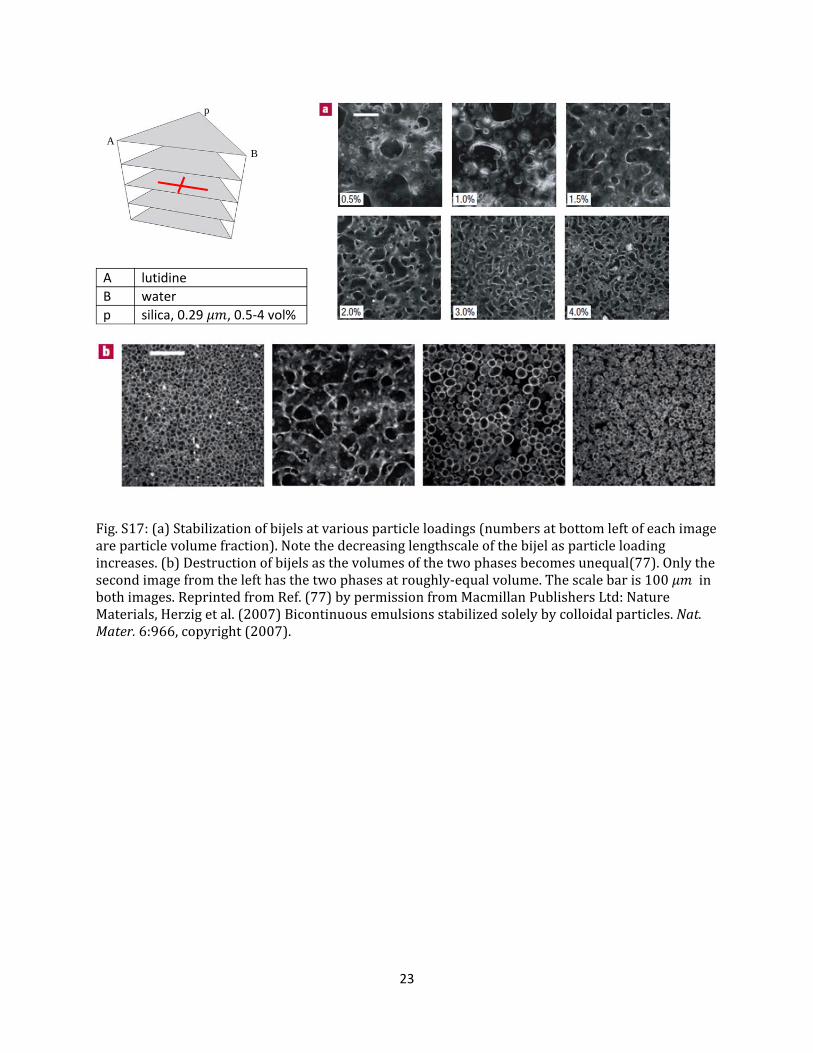
Fig.S17:(a)Stabilizationofbijelsatvariousparticleloadings(numbersatbottomleftofeachimageareparticlevolumefraction).Notethedecreasinglengthscaleofthebijelasparticleloadingincreases.(b)Destructionofbijelsasthevolumesofthetwophasesbecomesunequal(77).Onlythesecondimagefromthelefthasthetwophasesatroughly‐equalvolume.Thescalebaris100 inbothimages.ReprintedfromRef.(77)bypermissionfromMacmillanPublishersLtd:NatureMaterials,Herzigetal.(2007)Bicontinuousemulsionsstabilizedsolelybycolloidalparticles.Nat.Mater.6:966,copyright(2007).
A lutidine
B water
p silica, 0.29 , 0.5‐4 vol%
AB
p
24
Fig.S18:Structureofpolymerblendswithchangingcompositionwhenparticlesareroughlyequally‐wettedbybothphases(20).ThetopleftsamplelabeledE15‐0.75has15wt%polyethyleneoxideand0.75wt%particles,andthesameconventionisfollowedforallsamples.RightcolumnimageshavehighermagnificationthanleftcolumntoshowthatparticlesarecrowdedontheinterfaceinCandD,butnotinB.Thescalebaris500 intheleftcolumnofimagesand5 intherightcolumn.ImagesreproducedfromRef.(20),Nagarkar&Velankar(2013)Rheologyandmorphologyofmodelimmisciblepolymerblendswithmonodispersesphericalparticlesattheinterface.J.Rheol.57:901,withpermissionfromAIPPublishing.
A polyethylene oxide
B polyisobutylene
p silica, 2.7 , 0‐3.5 wt%
AB
p
25
Fig.S19:(a)Changesinstructurewhenanair/water/particlemixtureismixedbyshaking.Numbersatthetoparethe%SiOHgroupsontheparticlesurfaces(5).Notethatthehydrophilicityoftheparticlesincreaseswithincreasing%SiOH,with100%SiOHbeingfully‐hydrophilic.Allsampleswerepreparedwithwater:airina5:95ratioduringmixing,andwerethentransferredtothevials.(b)Granulesofwater(alsocalleddrywater)coatedwithhighlyhydrophobicparticles(20%SiOH),and(c)particle‐stabilizedfoamfrommoderatelyhydrophobicparticles(32%SiOH).Scalebarsare10mminbandc.ReprintedbypermissionfromMacmillanPublishersLtd:NatureMaterials,Binks&Murakami(2006)Phaseinversionofparticle‐stabilizedmaterialsfromfoamstodrywater.Nat.Mater.5:865,copyright(2006).
Fig.S20:(a)Structureofparticle‐stabilizedoilfoamswhentheparticle‐oil‐airmixturesaremixedbyshaking(91).Alltheliquidsin(a)arerelatively‐wettingtowardstheparticles,andallformfoams.Appearanceofmixtureswhen(b)theliquidfully‐wetstheparticle;heretheparticlesareengulfedbytheliquidandstayinsuspension.(c)theliquidispoorly‐wettingtowardstheparticles,andformsasoufflé‐likematerialwhichissimilartoapowderedliquid.ReproducedfromRef.(91),Binks&Rocher(2010)Stabilisationofliquid‐airsurfacesbyparticlesoflowsurfaceenergy.Phys.Chem.Chem.Phys.12:9169,withpermissionfromthePCCPOwnerSocieties.
A air
B water
p fumed silica ; particle:water in a 5:95 weight ratio
A B
p
A air
B various oils and polar liquids
p polytetrafluoroethylene; 10 , particle:liquid in a 5:95 weight ratio
A B
p
26
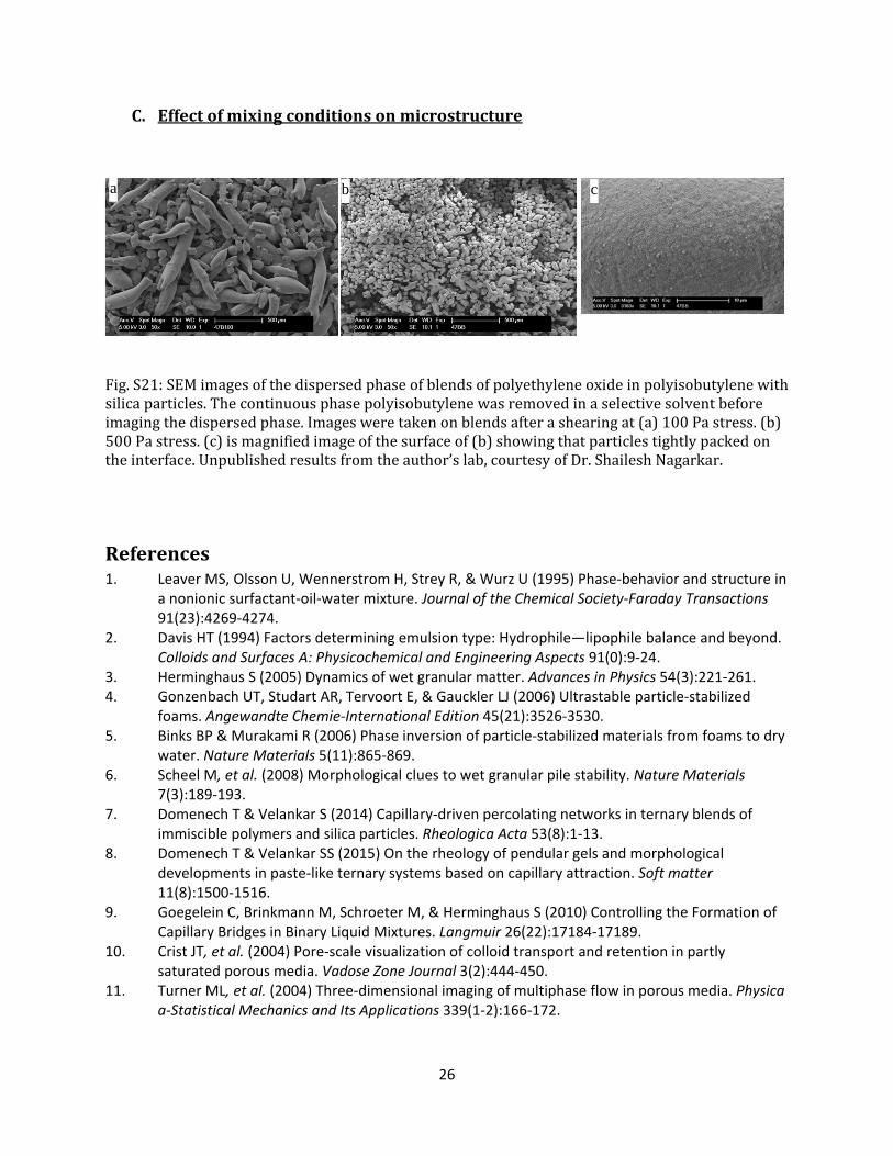
C. Effectofmixingconditionsonmicrostructure
Fig.S21:SEMimagesofthedispersedphaseofblendsofpolyethyleneoxideinpolyisobutylenewithsilicaparticles.Thecontinuousphasepolyisobutylenewasremovedinaselectivesolventbeforeimagingthedispersedphase.Imagesweretakenonblendsafterashearingat(a)100Pastress.(b)500Pastress.(c)ismagnifiedimageofthesurfaceof(b)showingthatparticlestightlypackedontheinterface.Unpublishedresultsfromtheauthor’slab,courtesyofDr.ShaileshNagarkar.
References1. Leaver MS, Olsson U, Wennerstrom H, Strey R, & Wurz U (1995) Phase‐behavior and structure in
a nonionic surfactant‐oil‐water mixture. Journal of the Chemical Society‐Faraday Transactions 91(23):4269‐4274.
2. Davis HT (1994) Factors determining emulsion type: Hydrophile—lipophile balance and beyond. Colloids and Surfaces A: Physicochemical and Engineering Aspects 91(0):9‐24.
3. Herminghaus S (2005) Dynamics of wet granular matter. Advances in Physics 54(3):221‐261. 4. Gonzenbach UT, Studart AR, Tervoort E, & Gauckler LJ (2006) Ultrastable particle‐stabilized
foams. Angewandte Chemie‐International Edition 45(21):3526‐3530. 5. Binks BP & Murakami R (2006) Phase inversion of particle‐stabilized materials from foams to dry
water. Nature Materials 5(11):865‐869. 6. Scheel M, et al. (2008) Morphological clues to wet granular pile stability. Nature Materials
7(3):189‐193. 7. Domenech T & Velankar S (2014) Capillary‐driven percolating networks in ternary blends of
immiscible polymers and silica particles. Rheologica Acta 53(8):1‐13. 8. Domenech T & Velankar SS (2015) On the rheology of pendular gels and morphological
developments in paste‐like ternary systems based on capillary attraction. Soft matter 11(8):1500‐1516.
9. Goegelein C, Brinkmann M, Schroeter M, & Herminghaus S (2010) Controlling the Formation of Capillary Bridges in Binary Liquid Mixtures. Langmuir 26(22):17184‐17189.
10. Crist JT, et al. (2004) Pore‐scale visualization of colloid transport and retention in partly saturated porous media. Vadose Zone Journal 3(2):444‐450.
11. Turner ML, et al. (2004) Three‐dimensional imaging of multiphase flow in porous media. Physica a‐Statistical Mechanics and Its Applications 339(1‐2):166‐172.
a b c
27
12. Heidlebaugh SJ, Domenech T, Iasella SV, & Velankar SS (2014) Aggregation and Separation in Ternary Particle/Oil/Water Systems with Fully Wettable Particles. Langmuir 30(1):63‐74.
13. Sirianni AF, Capes CE, & Puddington JE (1969) Recent experience with the spherical agglomeration process. The Canadian Journal of Chemical Engineering 47(2):166‐170.
14. House CI & Veal CJ (1992) Spherical agglomeration in minerals processing. Colloid and surface engineering: Applications in the process industries, ed Williams RA (Butterworth Heinemann, Oxford).
15. Pietsch W (2008) Agglomeration Processes: Phenomena, Technologies, Equipment (Wiley, Weinheim).
16. Capes CE & Darcovich K (1984) A survey of oil agglomeration in wet fine coal processing. Powder Technology 40(1‐3):43‐52.
17. Chary GHVC & Dastidar MG (2013) Comprehensive study of process parameters affecting oil agglomeration using vegetable oils. Fuel 106:285‐292.
18. Chow AHL & Leung MWM (1996) A study of the mechanisms of wet spherical agglomeration of pharmaceutical powders. Drug Development and Industrial Pharmacy 22(4):357‐371.
19. Rossetti D & Simons SJR (2003) A microscale investigation of liquid bridges in the spherical agglomeration process. Powder Technology 130(1‐3):49‐55.
20. Nagarkar S & Velankar SS (2013) Rheology and morphology of model immiscible polymer blends with monodisperse spherical particles at the interface. Journal of Rheology 57(3):901‐926.
21. Nagarkar SP & Velankar SS (2012) Morphology and rheology of ternary fluid‐fluid‐solid systems. Soft Matter 8(32):8464‐8477.
22. Thareja P, Moritz K, & Velankar SS (2010) Interfacially active particles in droplet/matrix blends of model immiscible homopolymers: Particles can increase or decrease drop size. Rheologica Acta 49(3):285‐298.
23. Steinmann S, Gronski W, & Friedrich C (2002) Influence of selective filling on rheological properties and phase inversion of two‐phase polymer blends. Polymer 43(16):4467‐4477.
24. Tanaka H, Lovinger AJ, & Davis DD (1994) Pattern Evolution Caused by Dynamic Coupling between Wetting and Phase‐Separation in Binary‐Liquid Mixture Containing Glass Particles. Physical Review Letters 72(16):2581‐2584.
25. Domenech T & Velankar SS (2015) Microstructure and phase inversion in three phase polymer/polymer/particle blends. In preparation.
26. Zhang M, et al. (2012) Morphology and rheology of poly(L‐lactide)/polystyrene blends filled with silica nanoparticles. Journal of Materials Science 47(3):1339‐1347.
27. Lee SH, Bailly M, & Kontopoulou M (2012) Morphology and Properties of Poly(propylene)/Ethylene‐Octene Copolymer Blends Containing Nanosilica. Macromolecular Materials and Engineering 297(1):95‐103.
28. Si M, et al. (2006) Compatibilizing bulk polymer blends by using organoclays. Macromolecules 39(14):4793‐4801.
29. Lee HS, Fasulo PD, Rodgers WR, & Paul DR (2005) TPO based nanocomposites. Part 1. Morphology and mechanical properties. Polymer 46(25):11673‐11689.
30. Cai XX, Li BP, Pan Y, & Wu GZ (2012) Morphology evolution of immiscible polymer blends as directed by nanoparticle self‐agglomeration. Polymer 53(1):259‐266.
31. Augsburger LL & Vuppala MK (1997) Chapter 2: Theory of Granulation. Handbook of Pharmaceutical Granulation Technology, ed Parikh DM (Marcel‐Dekker, New York).
32. Iveson SM, Litster JD, Hapgood K, & Ennis BJ (2001) Nucleation, growth and breakage phenomena in agitated wet granulation processes: a review. Powder Technology 117(1–2):3‐39.
33. Capes CE (1980) Chapter 4: Agitation methods ‐ Mixer agglomeration. Particle size enlargement, (Elsevier, Amsterdam).
28
34. Mills N (2007) Polymer foams handbook (Elsevier, Amsterdam) 1st Ed. 35. Lee ST, Park CB, & Ramesh NS (2007) Polymeric Foams: Science and Technology (CRC Press, Boca
Raton). 36. Zhai W, Park CB, & Kontopoulou M (2011) Nanosilica Addition Dramatically Improves the Cell
Morphology and Expansion Ratio of Polypropylene Heterophasic Copolymer Foams Blown in Continuous Extrusion. Industrial & Engineering Chemistry Research 50(12):7282‐7289.
37. Lee LJ, et al. (2005) Polymer nanocomposite foams. Composites Science and Technology 65(15‐16):2344‐2363.
38. Chen LM, Rende D, Schadler LS, & Ozisik R (2013) Polymer nanocomposite foams. Journal of Materials Chemistry A 1(12):3837‐3850.
39. Shen J, Han XM, & Lee LJ (2006) Nanoscaled reinforcement of polystyrene foams using carbon nanofibers. Journal of Cellular Plastics 42(2):105‐126.
40. Rodriguez‐Perez MA, et al. (2012) Foaming of EVA/starch blends: Characterization of the structure, physical properties, and biodegradability. Polymer Engineering & Science 52(1):62‐70.
41. Scheel M, et al. (2008) Liquid distribution and cohesion in wet granular assemblies beyond the capillary bridge regime. Journal of Physics‐Condensed Matter 20(49).
42. Binks BP (2002) Particles as surfactants ‐ similarities and differences. Current Opinion in Colloid and Interface Science 7(1‐2):21‐41.
43. Binks BP & Horozov TS eds (2006) Colloidal particles at liquid interfaces (Cambridge University Press, Cambridge).
44. Briggs TR (1921) Emulsions with Finely Divided Solids. Journal of Industrial & Engineering Chemistry 13(11):1008‐1010.
45. Tambe DE & Sharma MM (1994) The Effect of Colloidal Particles on Fluid‐Fluid Interfacial Properties and Emulsion Stability. Advances in Colloid and Interface Science 52:1‐63.
46. Binks BP & Lumsdon SO (2000) Influence of particle wettability on the type and stability of surfactant‐free emulsions. Langmuir 16(23):8622‐8631.
47. Binks BP & Lumsdon SO (2000) Effects of oil type and aqueous phase composition on oil‐water mixtures containing particles of intermediate hydrophobicity. Physical Chemistry Chemical Physics 2(13):2959‐2967.
48. Read ES, Fujii S, Amalvy JI, Randall DP, & Armes SP (2004) Effect of varying the oil phase on the behavior of pH‐responsive latex‐based emulsifiers: Demulsification versus transitional phase inversion. Langmuir 20(18):7422‐7429.
49. Binks BP & Lumsdon SO (2000) Transitional phase inversion of solid‐stabilized emulsions using particle mixtures. Langmuir 16(8):3748‐3756.
50. Tambe DE & Sharma MM (1993) Factors Controlling the Stability of Colloid‐Stabilized Emulsions .1. An Experimental Investigation. Journal of Colloid and Interface Science 157(1):244‐253.
51. Binks BP & Rodrigues JA (2007) Double inversion of emulsions by using nanoparticles and a di‐chain surfactant. Angewandte Chemie‐International Edition 46(28):5389‐5392.
52. Cui ZG, Shi KZ, Cui YZ, & Binks BP (2008) Double phase inversion of emulsions stabilized by a mixture of CaCO3 nanoparticles and sodium dodecyl sulphate. Colloids and Surfaces a‐Physicochemical and Engineering Aspects 329(1‐2):67‐74.
53. Binks BP & Rodrigues JA (2009) Influence of surfactant structure on the double inversion of emulsions in the presence of nanoparticles. Colloids and Surfaces a‐Physicochemical and Engineering Aspects 345(1‐3):195‐201.
54. Binks BP & Rodrigues JA (2005) Inversion of emulsions stabilized solely by ionizable nanoparticles. Angewandte Chemie‐International Edition 44(3):441‐444.
55. Binks BP, Murakami R, Armes SP, & Fujii S (2005) Temperature‐induced inversion of nanoparticle‐stabilized emulsions. Angewandte Chemie‐International Edition 44(30):4795‐4798.
29
56. Li J & Stoever HDH (2008) Doubly pH‐Responsive Pickering Emulsion. Langmuir 24(23):13237‐13240.
57. Yang H, Zhou T, & Zhang W (2013) A Strategy for Separating and Recycling Solid Catalysts Based on the pH‐Triggered Pickering‐Emulsion Inversion. Angewandte Chemie‐International Edition 52(29):7455‐7459.
58. Wang J, et al. (2013) Double Phase Inversion of Emulsions Stabilized by Layered Double Hydroxide Particles and Sodium Dodecyl Benzene Sulfonate. Journal of Dispersion Science and Technology 34(8):1067‐1073.
59. Zhang J, Li L, Xu J, & Sun D (2014) Effect of cetyltrimethylammonium bromide addition on the emulsions stabilized by montmorillonite. Colloid and Polymer Science 292(2):441‐447.
60. Zhou H, Sun M, & Zhang J (2014) Fabrication and Inversion of Pickering High Internal Phase Emulsions Stabilized by SiO2 Nanoparticles. Asian Journal of Chemistry 26(5):1540‐1542.
61. Williams M, Armes SP, Verstraete P, & Smets J (2014) Double Emulsions and Colloidosomes‐in‐Colloidosomes Using Silica‐Based Pickering Emulsifiers. Langmuir 30(10):2703‐2711.
62. Lu J, et al. (2015) Pickering emulsions stabilized by palygorskite particles grafted with pH‐responsive polymer brushes. Rsc Advances 5(13):9416‐9424.
63. Destribats M, et al. (2014) Pickering Emulsions: What Are the Main Parameters Determining the Emulsion Type and Interfacial Properties? Langmuir 30(31):9313‐9326.
64. White KA, et al. (2011) Inversion of particle‐stabilized emulsions of partially miscible liquids by mild drying of modified silica particles. Journal of Colloid and Interface Science 359(1):126‐135.
65. Schulman JH & Leja J (1954) Control of contact angles at the oil‐water‐solid interfaces ‐ Emulsions stabilized by solid particles. Transactions of the Faraday Society 50(6):598‐605.
66. Cui ZG, Yang LL, Cui YZ, & Binks BP (2010) Effects of Surfactant Structure on the Phase Inversion of Emulsions Stabilized by Mixtures of Silica Nanoparticles and Cationic Surfactant. Langmuir 26(7):4717‐4724.
67. Binks BP, Dyab AKF, & Fletcher PDI (2003) Novel emulsions of ionic liquids stabilised solely by silica nanoparticles. Chemical Communications (20):2540‐2541.
68. Binks BP, Philip J, & Rodrigues JA (2005) Inversion of silica‐stabilized emulsions induced by particle concentration. Langmuir 21(8):3296‐3302.
69. Binks BP & Rodrigues JA (2003) Types of phase inversion of silica particle stabilized emulsions containing triglyceride oil. Langmuir 19(12):4905‐4912.
70. Lee MN, Chan HK, & Mohraz A (2012) Characteristics of Pickering Emulsion Gels Formed by Droplet Bridging. Langmuir 28(6):3085‐3091.
71. Frost DS, Schoepf JJ, Nofen EM, & Dai LL (2012) Understanding droplet bridging in ionic liquid‐based Pickering emulsions. Journal of Colloid and Interface Science 383:103‐109.
72. Thareja P & Velankar S (2008) Rheology of immiscible blends with particle‐induced drop clusters. Rheologica Acta 47(2):189‐200.
73. French DJ, Taylor P, Fowler J, & Clegg PS (2015) Making and breaking bridges in a Pickering emulsion. Journal of Colloid and Interface Science 441:30‐38.
74. Horozov TS & Binks BP (2006) Particle‐stabilized emulsions: A bilayer or a bridging monolayer? Angewandte Chemie‐International Edition 45(5):773‐776.
75. Moghimi E, Goharpey F, & Foudazi R (2014) Role of droplet bridging on the stability of particle‐containing immiscible polymer blends. Rheologica Acta 53(2):165‐180.
76. Stratford K, Adhikari R, Pagonabarraga I, Desplat JC, & Cates ME (2005) Colloidal jamming at interfaces: A route to fluid‐bicontinuous gels. Science 309(5744):2198‐2201.
77. Herzig EM, White KA, Schofield AB, Poon WCK, & Clegg PS (2007) Bicontinuous emulsions stabilized solely by colloidal particles. Nature Materials 6(12):966‐971.
30
78. Lee MN & Mohraz A (2010) Bicontinuous Macroporous Materials from Bijel Templates. Advanced Materials 22(43):4836‐4841.
79. Clegg PS (2008) Fluid‐bicontinuous gels stabilized by interfacial colloids: low and high molecular weight fluids. Journal of Physics‐Condensed Matter 20(11):113101.
80. Gam S, et al. (2011) A jamming morphology map of polymer blend nanocomposite films. Soft Matter 7(16):7262‐7268.
81. Bai L, Fruehwirth J, Cheng X, & Macosko CW (2015) Interfacial silica nanoparticles stabilize cocontinuous polymer blends. arXiv:1502.00165 [cond‐mat.soft].
82. Potschke P & Paul DR (2003) Formation of Co‐continuous structures in melt‐mixed immiscible polymer blends. Journal of Macromolecular Science‐Polymer Reviews C43(1):87‐141.
83. Sumita M, Sakata K, Asai S, Miyasaka K, & Nakagawa H (1991) Dispersion of fillers and the electrical conductivity of polymer blends filled with carbon black. Polymer Bulletin 25:266‐271.
84. Soares BG, et al. (1995) Electrical‐Conductivity in Carbon Black‐Loaded Polystyrene‐Polyisoprene Blends ‐ Selective Localization of Carbon‐Black at the Interface. Polymer Bulletin 35(1‐2):223‐228.
85. Cheah K, Forsyth M, & Simon GP (2000) Processing and morphological development of carbon black filled conducting blends using a binary host of poly(styrene co‐acrylonitrile) and poly(styrene). Journal of Polymer Science Part B‐Polymer Physics 38(23):3106‐3119.
86. Calberg C, et al. (1999) Electrical and dielectric properties of carbon black filled co‐continuous two‐phase polymer blends. Journal of Physics D‐Applied Physics 32(13):1517‐1525.
87. Fenouillot F, Cassagnau P, & Majeste JC (2009) Uneven distribution of nanoparticles in immiscible fluids: Morphology development in polymer blends. Polymer 50(6):1333‐1350.
88. Tong W, et al. (2010) The morphology of immiscible PDMS/PIB blends filled with silica nanoparticles under shear flow. Colloid and Polymer Science 288(7):753‐760.
89. Koos E & Willenbacher N (2011) Capillary Forces in Suspension Rheology. Science 331(6019):897‐900.
90. Koos E & Willenbacher N (2012) Particle configurations and gelation in capillary suspensions. Soft Matter 8(14):3988‐3994.
91. Binks BP & Rocher A (2010) Stabilisation of liquid‐air surfaces by particles of low surface energy. Physical Chemistry Chemical Physics 12(32):9169‐9171.
92. Binks BP, Duncumb B, & Murakami R (2007) Effect of pH and salt concentration on the phase inversion of particle‐stabilized foams. Langmuir 23(18):9143‐9146.
93. Binks BP, Johnson AJ, & Rodrigues JA (2010) Inversion of 'dry water' to aqueous foam on addition of surfactant. Soft Matter 6(1):126‐135.
94. Binks BP, Sekine T, & Tyowua AT (2014) Dry oil powders and oil foams stabilised by fluorinated clay platelet particles. Soft Matter 10(4):578‐589.
95. Whitby CP, Bian X, & Sedev R (2012) Spontaneous liquid marble formation on packed porous beds. Soft Matter 8(44):11336‐11342.
96. Studart AR, et al. (2012) Metallic foams from nanoparticle‐stabilized wet foams and emulsions. Journal of Materials Chemistry 22(3):820‐823.
97. Gonzenbach UT, Studart AR, Tervoort E, & Gauckler LJ (2006) Stabilization of foams with inorganic colloidal particles. Langmuir 22(26):10983‐10988.
98. McHale G & Newton MI (2015) Liquid marbles: topical context within soft matter and recent progress. Soft matter 11(13):2530‐2546.
99. Bormashenko E (2012) New insights into liquid marbles. Soft Matter 8(43):11018‐11021. 100. Juillerat FK, Gonzenbach UT, Studart AR, & Gauckler LJ (2011) Self‐setting particle‐stabilized
foams with hierarchical pore structures. Materials Letters 64(13):1468‐1470.
31
101. Fujii S, Iddon PD, Ryan AJ, & Armes SP (2006) Aqueous particulate foams stabilized solely with polymer latex particles. Langmuir 22(18):7512‐7520.
102. Stocco A, Rio E, Binks BP, & Langevin D (2011) Aqueous foams stabilized solely by particles. Soft Matter 7(4):1260‐1267.
103. Murakami R & Bismarck A (2010) Particle‐Stabilized Materials: Dry Oils and (Polymerized) Non‐Aqueous Foams. Advanced Functional Materials 20(5):732‐737.
104. Dickinson E (2010) Food emulsions and foams: Stabilization by particles. Current Opinion in Colloid & Interface Science 15(1‐2):40‐49.
105. Stocco A, Drenckhan W, Rio E, Langevin D, & Binks BP (2009) Particle‐stabilised foams: an interfacial study. Soft Matter 5(11):2215‐2222.
106. Thareja P, Ising BP, Kingston SJ, & Velankar S (2008) Polymer foams stabilized by particles adsorbed at the air/polymer interface. Macromolecular Rapid Communications 29(15):1329‐1334.
107. Lobos J & Velankar SS (2013) Conference Proceedings: Improving thermoplastic foam stability in the molten state by interfacially‐adsorbed particles. Society of Plastics Engineers ‐ Annual Technical Meeting.
108. Cheng HL & Velankar SS (2008) Film climbing of particle‐laden interfaces. Colloids and Surfaces a‐Physicochemical and Engineering Aspects 315:275‐284.
109. Tavacoli JW, Thijssen JHJ, Schofield AB, & Clegg PS (2011) Novel, Robust, and Versatile Bijels of Nitromethane, Ethanediol, and Colloidal Silica: Capsules, Sub‐Ten‐Micrometer Domains, and Mechanical Properties. Advanced Functional Materials 21(11):2020‐2027.