Embed Size (px)
Citation preview

Translation of the original configuration manual 06/2014
English
Configuration manual UO-EM-EGS41 electronic overspeed switch
Electronic function module to U-ONE®
Read the configuration manual prior to assembly,
starting installation and handling!
Keep for future using!

Configuration manual UO-EM-EGS41
2
Trademark U-ONE is a registered trademark of Johannes Hübner Fabrik elektrischer Maschinen GmbH. Windows
® is a registered trademark of Microsoft Corporation in the United States and other countries.
Protected trademarks bearing a ™ or ® symbol are not always depicted as such in the manual.
However, the statutory rights of the respective owners remain unaffected. Manufacturer / publisher Johannes Hübner Fabrik elektrischer Maschinen GmbH Siemensstraße 7 35394 Giessen
Germany Phone: +49 641 / 7969-0 Fax: +49 641 / 73645 E-Mail: [email protected] www.huebner-giessen.com
Headquarters: Giessen Court of registration: Giessen Commercial register number: HRB 126 The manual has been drawn up with the utmost care and attention. Nevertheless, we cannot exclude the possibility of errors in form and content. It is strictly forbidden to reproduce this publication or parts of this publication in any form or by any means without the prior written permission of Johannes Hübner Fabrik elektrischer Maschinen GmbH. Subject to errors and changes due to technical improvements. Copyright © Johannes Hübner Fabrik elektrischer Maschinen GmbH. All rights reserved.
US
41_K
onfigM
an
ual_
En.d
oc
Build
: 7
172
Configuration manual UO-EM-EGS41
3
Directory
1 Setting up ........................................................................................................................ 4
1.1 Planning and configuration ......................................................................................................... 4 1.2 System requirements .................................................................................................................. 4 1.3 Installing the software ................................................................................................................. 5 1.4 Installing the driver manually ...................................................................................................... 6
2 Configuring ..................................................................................................................... 8
2.1 Fundamental procedure .............................................................................................................. 8 2.2 Configuration planning table ....................................................................................................... 9
3 Software description .....................................................................................................10
3.1 Head section ............................................................................................................................. 11 3.2 Information section ................................................................................................................... 12 3.3 Display section .......................................................................................................................... 12 3.4 Establishing a connection and logging on ................................................................................ 13 3.5 Online Help ............................................................................................................................... 14
4 Parameters 1 ..................................................................................................................14
4.1 Inverse rotation evaluation........................................................................................................ 17 4.2 Underspeed .............................................................................................................................. 17 4.3 Rotation-direction dependent switching .................................................................................... 17 4.4 Switch delay .............................................................................................................................. 17 4.5 Slip detection ............................................................................................................................ 17
5 Parameters 2 ..................................................................................................................18
5.1 Identification and password ...................................................................................................... 18 5.2 Delete errors ............................................................................................................................. 18 5.3 Switching contact test ............................................................................................................... 19
6 Monitoring screen ..........................................................................................................19
6.1 Functions .................................................................................................................................. 20
7 Operating data ...............................................................................................................21
8 Pulldown-Menu „file“ .....................................................................................................21
8.1 Save monitoring data ................................................................................................................ 21 8.2 Save parameter ........................................................................................................................ 21 8.3 Save device data ...................................................................................................................... 21
9 Pull-down-Menu „Settings“ ...........................................................................................22
9.1 Reset Password ........................................................................................................................ 22 9.2 Boot loader firmware ................................................................................................................. 23
10 Error table ......................................................................................................................24
11 Notes on configuration ..................................................................................................25
11.1 Switch delay .............................................................................................................................. 25 11.2 Slip angle detection .................................................................................................................. 25 11.3 Diagnostics output .................................................................................................................... 25
12 Index ...............................................................................................................................26
Configuration manual UO-EM-EGS41
4
1 Setting up
Allow sufficient time to plan the integration and configuration of the UO-EM-EGS41. Please remember that planning and configuration errors can put people at risk. Put organizational measures in place to guarantee safety during configuration procedures!
Ensure that the system cannot enter any dangerous states during the configuration procedures includ-ing in that part of the system monitored by devices connected to the UO-EM-EGS41.
To configure the UO-EM-EGS41 you require the following:
Operating instructions belonging to the UO-EM-EGS41
Notebook/PC running a Windows®
operating system
The configuration software EGS41Pro
A UO-EM-EGS41 device ready for operations
Connecting cable to connect the notebook/PC with the UO-EM-EGS41 device
1.1 Planning and configuration
Caution!
Ensure you have planned the application thoroughly before you begin to configure the UO-EM-EGS41!
Amongst other considerations the planning must include:
A detailed safety analysis of the planned application
A complete list of all required devices, their connections as well as the signals provided or re-quired by these devices.
In addition, the following conditions must be fulfilled:
The UO-EM-EGS41 must be connected to the power supply.
The safety components must be electrically connected to the UO-EM-EGS41.
Read also the appropriate operating and assembly instructions.
1.2 System requirements
For configuration purposes it is possible to use any commercially available Windows® notebooks/PCs
that fulfil the following system requirements:
- Windows® XP SP3 / Vista / 7/8/8.1
- CD-ROM drive
- Available USB port
Configuration manual UO-EM-EGS41
5
1.3 Installing the software
Ensure the UO-EM-EGS41 device and your notebook/PC are connected via the USB cable. Close the automatically started „Found new hardware wizard“ with a click on “Cancel“.
Place the supplied CD containing the software into the CD drive or, alternatively, download the Set-
up.exe. If the Setup.exe does not run automatically, navigate via Explorer on the CD-ROM drive and
there start the Setup.exe.
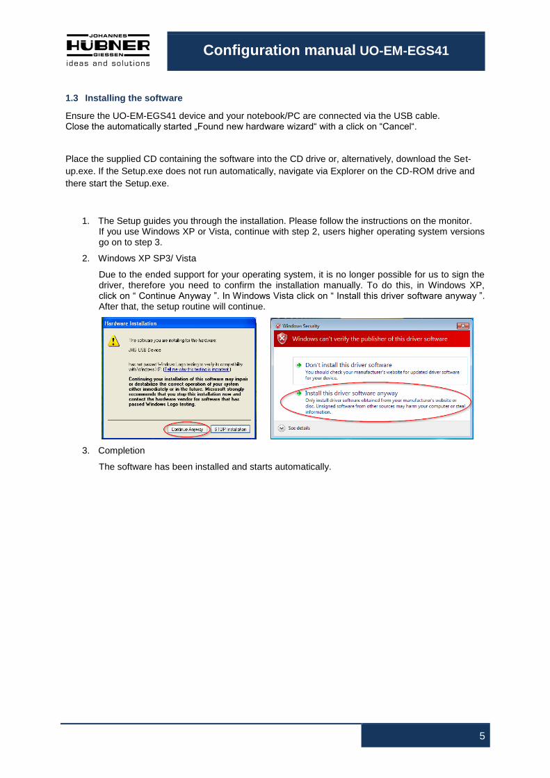
1. The Setup guides you through the installation. Please follow the instructions on the monitor. If you use Windows XP or Vista, continue with step 2, users higher operating system versions go on to step 3.
2. Windows XP SP3/ Vista
Due to the ended support for your operating system, it is no longer possible for us to sign the driver, therefore you need to confirm the installation manually. To do this, in Windows XP, click on “ Continue Anyway ”. In Windows Vista click on “ Install this driver software anyway ”. After that, the setup routine will continue.
3. Completion
The software has been installed and starts automatically.
Configuration manual UO-EM-EGS41
6
1.4 Installing the driver manually
PLEASE NOTE!
You must log into a user account with administrator rights to install the software. Ensure all programs are closed.
If it is necessary to install the driver manually, depending on your operating system, please check the following steps.
Connect the supplied USB cable with the UO-EM-EGS41 device and your notebook/PC
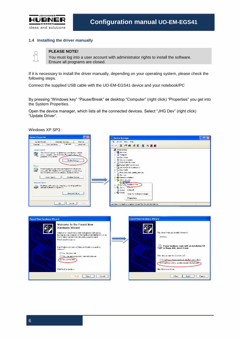
By pressing “Windows key” “Pause/Break” or desktop “Computer” (right click) “Properties” you get into the System Properties.
Open the device manager, which lists all the connected devices. Select “JHG Dev” (right click) “Update Driver”.
Windows XP SP3 :
Configuration manual UO-EM-EGS41
7
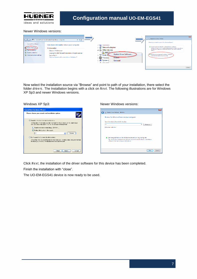
Newer Windows versions:
Now select the installation source via “Browse” and point to path of your installation, there select the folder drivers. The Installation begins with a click on Next. The following illustrations are for Windows XP Sp3 and newer Windows versions.
Windows XP Sp3: Newer Windows versions:
Click Next, the installation of the driver software for this device has been completed.
Finish the installation with “close”.
The UO-EM-EGS41 device is now ready to be used.
Configuration manual UO-EM-EGS41
8
2 Configuring
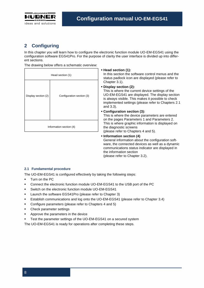
In this chapter you will learn how to configure the electronic function module UO-EM-EGS41 using the configuration software EGS41Pro. For the purpose of clarity the user interface is divided up into differ-ent sections.
The drawing below offers a schematic overview:
Head section (1): In this section the software control menus and the status padlock icon are displayed (please refer to Chapter 3.1).
Display section (2): This is where the current device settings of the UO-EM-EGS41 are displayed. The display section is always visible. This makes it possible to check implemented settings (please refer to Chapters 2.1 and 3.3).
Configuration section (3): This is where the device parameters are entered on the pages Parameters 1 and Parameters 2. This is where graphic information is displayed on the diagnostic screens (please refer to Chapters 4 and 5).
Information section (4) General information about the configuration soft-ware, the connected devices as well as a dynamic communications status indicator are displayed in the information section (please refer to Chapter 3.2).
2.1 Fundamental procedure
The UO-EM-EGS41 is configured effectively by taking the following steps:
Turn on the PC
Connect the electronic function module UO-EM-EGS41 to the USB port of the PC
Switch on the electronic function module UO-EM-EGS41
Launch the software EGS41Pro (please refer to Chapter 3)
Establish communications and log onto the UO-EM-EGS41 (please refer to Chapter 3.4)
Configure parameters (please refer to Chapters 4 and 5)
Check parameter settings
Approve the parameters in the device
Test the parameter settings of the UO-EM-EGS41 on a secured system
The UO-EM-EGS41 is ready for operations after completing these steps.
Head section (1):
Display section (2)
Configuration section (3)
Information section (4)

Configuration manual UO-EM-EGS41
9
2.2 Configuration planning table
PLEASE NOTE!
A configuration planning table is provided below. Use a printout or a copy of the planning table below to plan the configuration of the UO-EM-EGS41.
Parameter Factory setting New value
User device designation
Inverse speed alignment Not active
Underspeed Not active
Speed dependent switching Not active
Switch delay Not active
Switch 1 active Not active
Switch 2 active Not active
S1R – nov_on 90 rpm
S1R – nov_off 100 rpm
S2R – nov_on 180 rpm
S2R – nov_off 200 rpm
Configuration manual UO-EM-EGS41
10
3 Software description
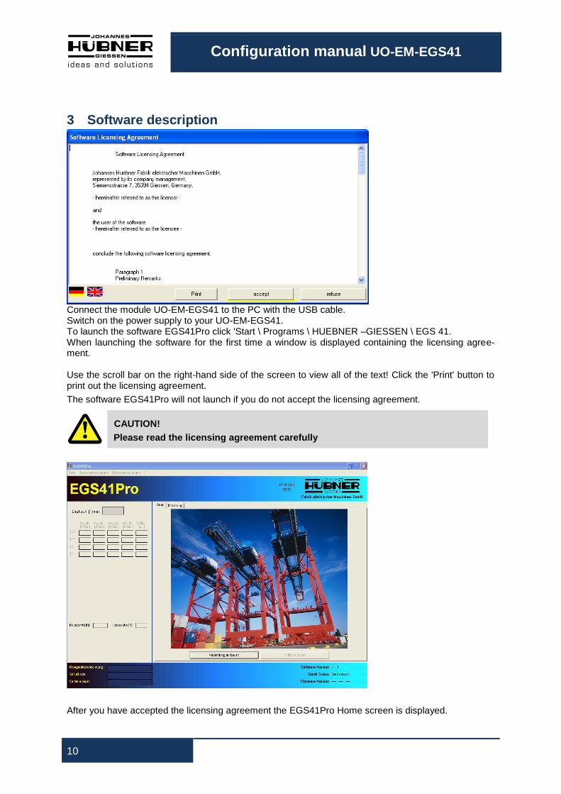
Connect the module UO-EM-EGS41 to the PC with the USB cable. Switch on the power supply to your UO-EM-EGS41. To launch the software EGS41Pro click 'Start \ Programs \ HUEBNER –GIESSEN \ EGS 41. When launching the software for the first time a window is displayed containing the licensing agree-ment. Use the scroll bar on the right-hand side of the screen to view all of the text! Click the 'Print' button to print out the licensing agreement.
The software EGS41Pro will not launch if you do not accept the licensing agreement.
CAUTION!
Please read the licensing agreement carefully
After you have accepted the licensing agreement the EGS41Pro Home screen is displayed.

Configuration manual UO-EM-EGS41
11
The individual functions on the 'Home screen' are described in more detail in the Chapter 3.1. To establish a connection to the UO-EM-EGS41 proceed as follows: On the Home screen click the 'Establish connection' button.
Communications have been successfully established when the communication status symbol rotates. You can now begin to configure the device.
3.1 Head section
The menu bar containing basic commands to operate the software is located in the head section.
PLEASE NOTE!
Menu commands are presently unavailable if dimmed (for example, because the config-uration software is unable to communicate with the UO-EM-EGS41).
First define the user language for the user interface under 'System settings/language'.
If required, click '?\Help' to call up the online context-sensitive Help.
To exit the program click 'File\Exit'.
The current log-in status is displayed in the middle of the head section. A padlock with an open shack-le symbolizes that the configuration is not yet safeguarded against unauthorized alterations.
A closed padlock indicates that the configuration is securely safeguarded against unauthorized altera-tions. Chapter 5 'Parameter 2 page' contains details on safeguarding the configuration.
The user level with which the user is logged onto the device is displayed below the padlock symbol (in this example the status is: User.
Configuration manual UO-EM-EGS41
12
3.2 Information section
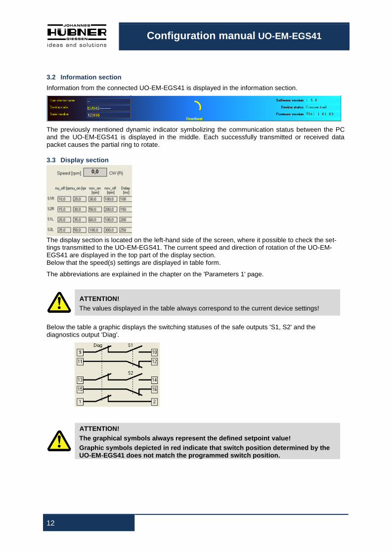
Information from the connected UO-EM-EGS41 is displayed in the information section.
The previously mentioned dynamic indicator symbolizing the communication status between the PC and the UO-EM-EGS41 is displayed in the middle. Each successfully transmitted or received data packet causes the partial ring to rotate.
3.3 Display section
The display section is located on the left-hand side of the screen, where it possible to check the set-tings transmitted to the UO-EM-EGS41. The current speed and direction of rotation of the UO-EM-EGS41 are displayed in the top part of the display section. Below that the speed(s) settings are displayed in table form.
The abbreviations are explained in the chapter on the 'Parameters 1' page.
ATTENTION!
The values displayed in the table always correspond to the current device settings!
Below the table a graphic displays the switching statuses of the safe outputs 'S1, S2' and the diagnostics output 'Diag'.
ATTENTION!
The graphical symbols always represent the defined setpoint value!
Graphic symbols depicted in red indicate that switch position determined by the UO-EM-EGS41 does not match the programmed switch position.
Configuration manual UO-EM-EGS41
13
The reason why the switch symbol is highlighted red is because the switch is either defective or not connected correctly. The number of hours [h] in operation and the PCB temperature of the connected device are displayed below the switch symbol. When a switch is inactive it appears dimmed. Text highlighted red indicates that a device fault has occurred (see Chapter 10).
3.4 Establishing a connection and logging on
Click the button 'Establish connection' to establish communications between the configuration software and the UO-EM-EGS41 device.
The rotating communications status indicator is displayed.
Data relating to device identification such as user designation, article code and the serial number are read out of the device and displayed in the information area.
The device status on the right-hand side of the information area changes to 'connected'.
Device data in the information section is refreshed approx. once per second.
You have now accessed the lowest user level. In this level you are able to view the settings of the connected UO-EM-EGS41. On the 'Monitoring' screen you are able to observe the positions of the switches analogous to an oscilloscope. Further details are available in Chapter 6.
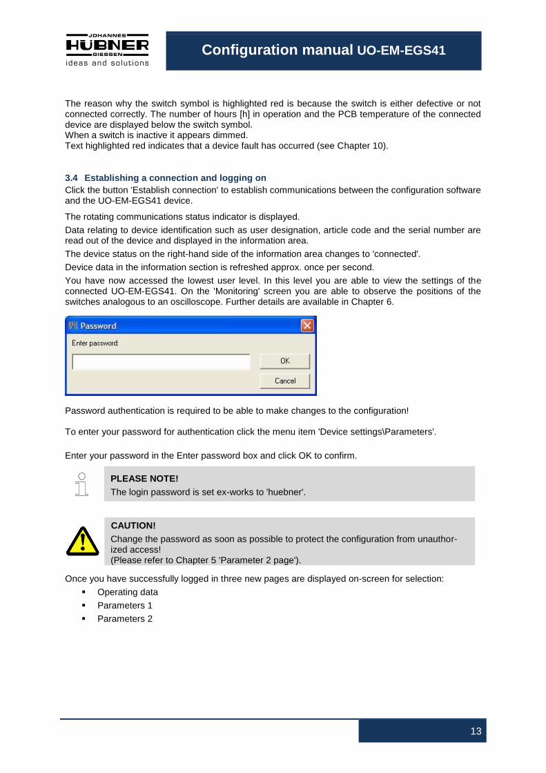
Password authentication is required to be able to make changes to the configuration! To enter your password for authentication click the menu item 'Device settings\Parameters'.
Enter your password in the Enter password box and click OK to confirm.
PLEASE NOTE!
The login password is set ex-works to 'huebner'.
CAUTION!
Change the password as soon as possible to protect the configuration from unauthor-ized access! (Please refer to Chapter 5 'Parameter 2 page').
Once you have successfully logged in three new pages are displayed on-screen for selection:
Operating data
Parameters 1
Parameters 2
Configuration manual UO-EM-EGS41
14
Changes are made to the settings of the UO-EM-EGS41 on the pages Parameters 1 and Parameters 2. On the Operating data page you are able to view a collation of all of the device settings and print these out for documentation purposes.
3.5 Online Help
Press 'F1' to display additional information about the individual functions.
4 Parameters 1
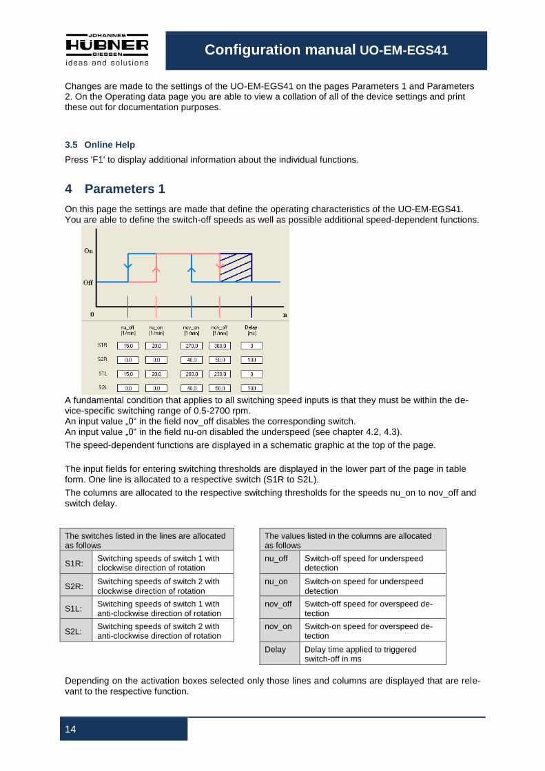
On this page the settings are made that define the operating characteristics of the UO-EM-EGS41. You are able to define the switch-off speeds as well as possible additional speed-dependent functions.
A fundamental condition that applies to all switching speed inputs is that they must be within the de-vice-specific switching range of 0.5-2700 rpm. An input value „0“ in the field nov_off disables the corresponding switch. An input value „0“ in the field nu-on disabled the underspeed (see chapter 4.2, 4.3).
The speed-dependent functions are displayed in a schematic graphic at the top of the page.
The input fields for entering switching thresholds are displayed in the lower part of the page in table form. One line is allocated to a respective switch (S1R to S2L).
The columns are allocated to the respective switching thresholds for the speeds nu_on to nov_off and switch delay.
Depending on the activation boxes selected only those lines and columns are displayed that are rele-vant to the respective function.
The switches listed in the lines are allocated as follows
The values listed in the columns are allocated as follows
S1R: Switching speeds of switch 1 with clockwise direction of rotation
nu_off Switch-off speed for underspeed detection
S2R: Switching speeds of switch 2 with clockwise direction of rotation
nu_on Switch-on speed for underspeed detection
S1L: Switching speeds of switch 1 with anti-clockwise direction of rotation
nov_off Switch-off speed for overspeed de-tection
S2L: Switching speeds of switch 2 with anti-clockwise direction of rotation
nov_on Switch-on speed for overspeed de-tection
Delay Delay time applied to triggered
switch-off in ms

Configuration manual UO-EM-EGS41
15
CAUTION!
When switch delay is activated the actual switch-off speed is higher than the set switch-off speed! Observe also information on determining the switching deviation described in the Op-erating and Assembly instruction UO-EM-EGS41!
After making changes to the switching speed settings click the 'Check input' button to check the new settings do not violate restrictions.
Restrictions:
nov_on < 0,9 * nov_off
nu_on < 0,9 * nov_on
nov_off < 0,9 * nu_on (or nu_off = nu_on = 0)
0.5 ° < slip angle ≤ 90°
Once the check has been completed successfully the data is stored to a temporary memory in the connected device. Flawed entries are highlighted red and data transmission to the device is prevent-ed.
To indicate that the data has not yet been accepted on a permanent basis the entry and display areas are each displayed with a red frame.
To begin the process of accepting the changes permanently clicks the button 'Store data in device'.

Configuration manual UO-EM-EGS41
16
You will again be required by a security prompt to verify and confirm your changes. Click the 'Confirm' button to confirm the changes you have undertaken and store these permanently in the connected device. To reject the changes click the 'Reject' button. The data in the temporary memory will be deleted.
PLEASE NOTE!
Before the settings can be accepted and used by the UO-EM-EGS41 they must be saved to the device; to do so click the 'Save data in device' button then click the 'Con-firm' button in the 'Confirm data' dialog box.
The respective activation check boxes are in the Overspeed switch configuration dialogue box on the right of the page. As there are no restrictions to observe the settings are transmitted immediately to the temporary memory in the connected device. For information on the activation boxes please refer to the chapters 4.1, 4.2, 4.3 and 4.4.
Configuration manual UO-EM-EGS41
17
4.1 Inverse rotation evaluation
Clockwise rotation for the switches S1R and S2R is defined as anti-clockwise rotation when viewing the end of the shaft of the UO-EM-EGS41. When inverse rotation evaluation is activated the alloca-tions for S1R and S1L are inverted.
4.2 Underspeed
Underspeed is detected. Below the speed nu_off the respective switch is open (off). The switch is closed again when the speed exceeds nu_on. The input columns for 'nu_on' and 'nu_off' are displayed if underspeed detection is activated.
4.3 Rotation-direction dependent switching
The switching speeds S1R and S2R apply to clockwise direction of rotation. The speeds S1L and S2L apply to anti-clockwise direction of rotation. The input lines for S1L and S2L are displayed if rotation direction dependent switching is activated.
If 'Rotation direction dependent switching' is not activated the switches S1 and S2 are not labelled with a rotation indicator R or L. The switching speeds entered apply independent of the direction of rota-tion.
4.4 Switch delay
The adjustable switch delay facility suppresses the switch-off function if the maximum speed is ex-ceeded only briefly. That can be appropriate for example during load shedding. When the speeds nov_off are exceeded the switches S1 and S2 are opened only after the delay time set in the 'Delay' field has elapsed. The delay time can be set between 0 and 300 ms. The switch-off function is not triggered if the speed again falls below the nov_off value within the set delay time.
PLEASE NOTE!
The delay time applies only to the switch-off function when the defined nov_off speed is exceeded. All other switching operations are triggered immediately.
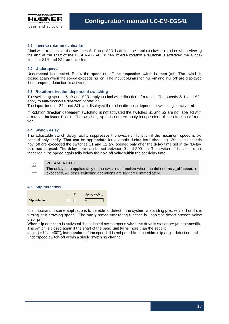
4.5 Slip detection
It is important in some applications to be able to detect if the system is standing precisely still or if it is turning at a crawling speed. The rotary speed monitoring function is unable to detect speeds below 0.25 rpm. When slip detection is activated the selected switch opens when the drive is stationary (at a standstill). The switch is closed again if the shaft of the basic unit turns more than the set slip angle ( ±1° … ±90°), independent of the speed. It is not possible to combine slip angle detection and underspeed switch-off within a single switching channel.

Configuration manual UO-EM-EGS41
18
5 Parameters 2
On this page the settings are made that define the safety-relevant characteristics of the UO-EM-EGS41.
5.1 Identification and password
In the middle section, you can give the device any user device name. This makes it easier to allocate UO-EM-EGS41 to its place of installation (e.g. "hoist 22"). The device name is limited to 12 characters.
Furthermore, in the second line of the middle section, you can define a new password for access to the configuration. With this password, only an authorized group of users will be able to change the configuration. To verify your authorization, enter the current password in the left box and the new password in the right box.
Press "change" to activate the new password in the device.
The password must be created from the alphanumeric characters a-z, A-Z and 1-9. The maximum
length of the password is limited to 12 characters.
PLEASE NOTE
The password on delivery of UO-EM-EGS41 is "huebner". Please note that you must enter a new password to protect the configuration from unau-thorized changes!
When the factory-set password is changed the padlock symbol at the top of the screen is displayed
closed.
To save changes permanently to the device click the 'Save data to device' button.
If an assigned user password has been lost, see chapter 9.1
5.2 Delete errors
It is possible to delete displayed error messages in the safety settings section. This also resets the
connected device.
If the cause of the error has not been rectified the internal diagnostics displays the error message
again after the connected device is reset.
Load factory settings: All settings made in the device are returned to the original factory settings.
CAUTION!
Loading the factory defaults irrevocably overwrites all configuration settings, including the safety settings!
Configuration manual UO-EM-EGS41
19
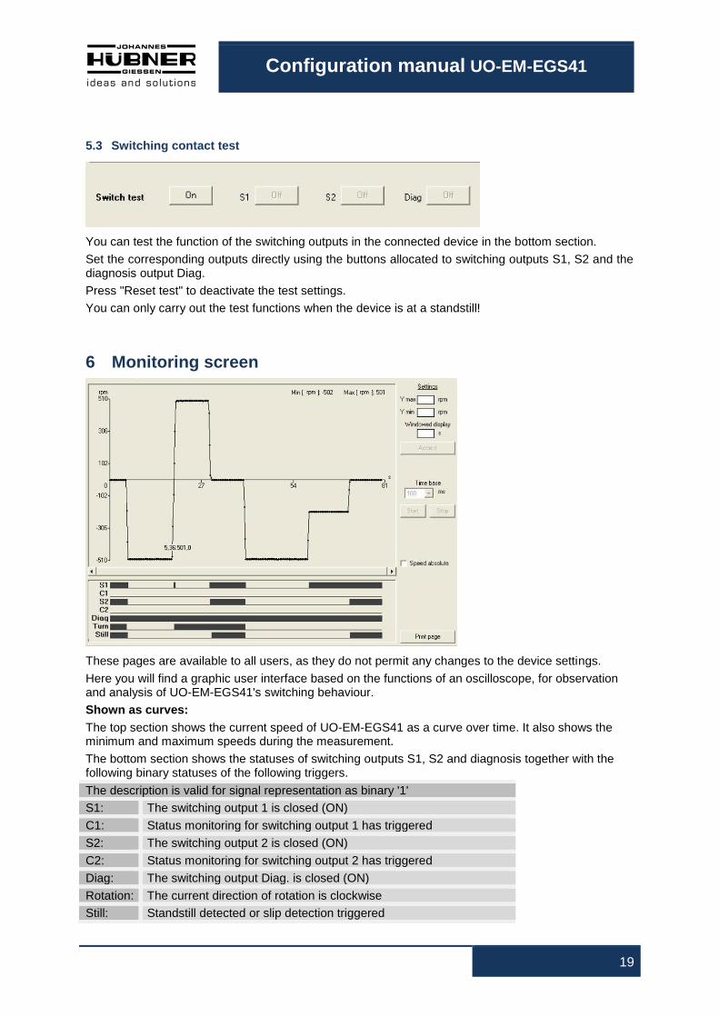
5.3 Switching contact test
You can test the function of the switching outputs in the connected device in the bottom section.
Set the corresponding outputs directly using the buttons allocated to switching outputs S1, S2 and the diagnosis output Diag.
Press "Reset test" to deactivate the test settings.
You can only carry out the test functions when the device is at a standstill!
6 Monitoring screen
These pages are available to all users, as they do not permit any changes to the device settings.
Here you will find a graphic user interface based on the functions of an oscilloscope, for observation and analysis of UO-EM-EGS41's switching behaviour.
Shown as curves:
The top section shows the current speed of UO-EM-EGS41 as a curve over time. It also shows the minimum and maximum speeds during the measurement.
The bottom section shows the statuses of switching outputs S1, S2 and diagnosis together with the following binary statuses of the following triggers.
The description is valid for signal representation as binary '1'
S1: The switching output 1 is closed (ON)
C1: Status monitoring for switching output 1 has triggered
S2: The switching output 2 is closed (ON)
C2: Status monitoring for switching output 2 has triggered
Diag: The switching output Diag. is closed (ON)
Rotation: The current direction of rotation is clockwise
Still: Standstill detected or slip detection triggered

Configuration manual UO-EM-EGS41
20
6.1 Functions
Representation scaling:
The input fields for entering values to adapt scaling are located on the right-hand side of the speed graphic.
By entering the appropriate values in the 'Ymax' and 'Ymin' fields you can limit representations in the speed range.
The 'Time rate' value determines the logging rate.
The "Windowed display" button toggles between displaying the complete log and a display with an adjustable window width in which the current speed value is displayed on the right-hand side of the diagram.
Click the 'Accept' button for the settings to take effect.
Click the 'Start' and 'Stop' buttons to start, stop or end the logging procedure.
Once the logging procedure has been completed it is possible to increase the size of individual sec-tions by holding down the left mouse button and dragging the respective window corner. Use a right click to reset the procedure.

Configuration manual UO-EM-EGS41
21
7 Operating data Here you can see a summary overview of all settings for the connected UO-EM-EGS41. No settings can be adjusted here. The top section shows all major device settings and the parameters adjusted under "Parameter 2" with their current values.
The bottom section contains a table showing the last 9 errors with detailed information. (chapter 10). Press "Print page" to trigger a print-out of all data shown on the page including the configuration set-tings shown in the display section. A Windows
® printer must be installed on your computer so that you
can make a print-out.
8 Pulldown-Menu „file“
With „Export device data“ can be saved in the PC and with “Import device data” can be trans-ferred from the PC to the device.
8.1 Save monitoring data
„File Export Monitoring data“ saves the recorded monitoring data (*.s41) in the PC.
With „file Import Monitoring data“ the saved data will be displayed on the page monitoring.
This function is only “offline” available.
Also monitoring data can be exported as CSV, in order to edit or process them later with Excel.
8.2 Save parameter
„File Export Parameter“ saves the user parameter (*.par) in the PC. With „File Import Parameter“ the user parameters are loaded into the input forms of EGS41pro software and can be saved in the device by the user after testing.
The function can also be used for transmission of user parameters to other UO-EM-EGS41 devices.
8.3 Save device data
„File Export Device Data“ saves the device data (*.edt) in the selected folder.
The data can be used by the manufacturer of the device for failure analysis.
Configuration manual UO-EM-EGS41
22
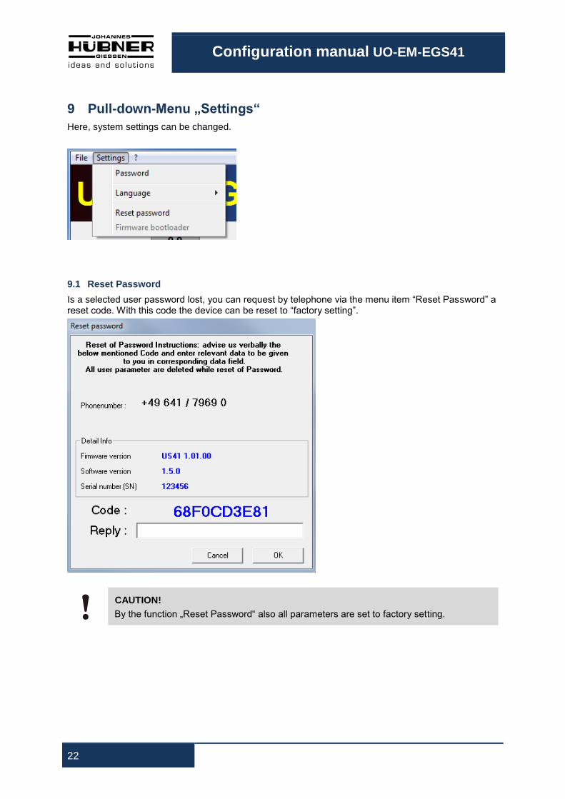
9 Pull-down-Menu „Settings“
Here, system settings can be changed.
9.1 Reset Password
Is a selected user password lost, you can request by telephone via the menu item “Reset Password” a reset code. With this code the device can be reset to “factory setting”.
CAUTION!
By the function „Reset Password“ also all parameters are set to factory setting.
Configuration manual UO-EM-EGS41
23
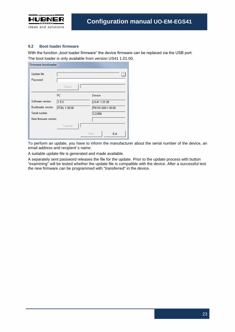
9.2 Boot loader firmware
With the function „boot loader firmware“ the device firmware can be replaced via the USB port.
The boot loader is only available from version US41 1.01.00.
To perform an update, you have to inform the manufacturer about the serial number of the device, an email address and recipient´s name.
A suitable update file is generated and made available.
A separately sent password releases the file for the update. Prior to the update process with button "examining" will be tested whether the update file is compatible with the device. After a successful test the new firmware can be programmed with "transferred" in the device.

Configuration manual UO-EM-EGS41
24
10 Error table
Error message Description
Dg_Intern [FFxx]
Device error
Dg_TempMain [0601, FE01]
Overtemperature in device
Dg_TempKK [0602, FE02]
Overtemperature in switch
Dg_ExtOv [0603, FE03]
Max. permissible supply voltage exceeded
Dg_n_Fatal [0604, FE04]
Non-permissible high speed
Dg_ExtUv [0605, FE05]
Below lowest permissible supply voltage
Dg_IncErr [0606, FE06]
Flawed incremental value
Dg_AbsErr [0607, FE07]
Flawed absolute value
Error [FExx]
Error
FatalError [FFxx]
Fatal error
Error category:
Error: The switches S1, S2 and Diag are opened.
To reset to the normal state interrupt the power supply via the reset input or click 'Delete error' in the software 'EGS41Pro'. The 'Delete error' command initiates a restart. If the error persists the device remains in the er-ror state.
Fatal error: The switches S1, S2 and Diag are opened.
To reset to the normal state click "Delete error" in the software 'EGS41Pro'. The 'Delete error' command initiates a restart. If the error persists the device remains in the er-ror state.
The device enters a 'safe state' in the event an error or fatal error occurs. In addition, the error causing
the problem is displayed.

Configuration manual UO-EM-EGS41
25
11 Notes on configuration
It is only possible to configure the device with a single password (user rights: administrator). The facto-
ry-set administrator password is: huebner. For reasons of safety it is strongly advised that you create a
user-defined password (max. 12 characters). Information on how to change the password is available
on page Parameter2.
11.1 Switch delay
Activating switch delay leads to increased switch-off speeds when speeds are accelerating in the
switching point. Before activating the switch delay ensure the switch-off speed cannot reach danger-
ously high speeds.
11.2 Slip angle detection
The switch remains open if the switch-off speed is reached within the set slip angle.
11.3 Diagnostics output
The diagnostics output is not a safety output.
Configuration manual UO-EM-EGS41
26
12 Index
C
Configuration planning table 18
Configuring 17
D
Delete errors 27
Diagnostics output 34
Display section 21
E
Error table 33
Establishing a connection and logging on 22
F
Functions 29
Fundamental procedure 17
H
Head section 20
I
Identification and password 27
Information section 21
Installing the driver on Vista / 7 11
Installing the drivers on XP 6
Installing the software on Vista / 7 14
Installing the software on XP 8
Inverse rotation evaluation 26
M
Monitoring screen 28
N
Notes on configuration 34
O
Operating data 30
P
Parameters 1 23
Parameters 2 27
Planning and configuration 5
R
Rotation direction dependent switching 26
S
Setting up 5
Slip angle detection 34
Slip detection 26
Software description 19
Switch delay 26, 34
Switching contact test 28
System requirements 5
U
Underspeed 26