Embed Size (px)
Citation preview
The 11th International Fluid Power Conference, 11. IFK, March 19-21, 2018, Aachen, Germany
2 State of the Art
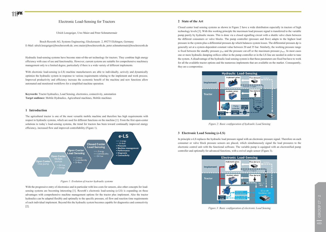
Closed center load sensing systems as shown in Figure 2 have a wide distribution especially in tractors of high technology levels [3]. With this working principle the maximum load pressure signal is transferred to the variable pump purely by hydraulic means. This is done via a closed signalling circuit with a shuttle valve chain between the different consumers or valve blocks. The pump controller (pressure and flow) adapts to the highest load pressure in the system plus a differential pressure Δp which balances system losses. The differential pressure Δp is generally set at a system-dependent constant value between 20 and 35 bar. Similarly, the working pressure range is fixed between the standby pressure pstb and the pressure cut-off or the maximum pressure pmax. In most cases one or more hydraulic damping orifices either in the pump controller or in the LS line are needed in order to tune the system. A disadvantage of the hydraulic load sensing system is that these parameters are fixed but have to work for all the available tractor options and the numerous implements that are available on the market. Consequently, they are a compromise.
Figure 2: Basic configuration of hydraulic Load Sensing
3 Electronic Load Sensing (e-LS)
In principle e-LS replaces the hydraulic load pressure signal with an electronic pressure signal. Therefore on each consumer or valve block pressure sensors are placed, which simultaneously signal the load pressures to the electronic control unit with the functional software. The variable pump is equipped with an electronified pump controller and optionally for advanced functions, with a swivel angle sensor (Figure 3).
Figure 3: Basic configuration of electronic Load Sensing
The 11th International Fluid Power Conference, 11. IFK, March 19-21, 2018, Aachen, Germany
Electronic Load-Sensing for Tractors
Ulrich Lenzgeiger, Uwe Maier and Peter Schmuttermair
Bosch Rexroth AG, Systems Engineering, Glockeraustr. 2, 89275 Elchingen, Germany E-Mail: [email protected], [email protected], [email protected]
Hydraulic load-sensing systems have become state-of-the-art technology for tractors. They combine high energy efficiency with ease of use and functionality. However, current systems are suitable for comprehensive machinery management only to a limited degree, particularly if there is a wide variety of different implements.
With electronic load-sensing (e-LS) machine manufacturers are able to individually, actively and dynamically optimize the hydraulic system in response to various requirements relating to the implement and work process. Improved productivity and efficiency increase the economic benefit of the machine and new functions allow automated and monitored workflows for a simplified machine operation.
Keywords: Tractor hydraulics, Load Sensing, electronics, connectivity, automation Target audience: Mobile Hydraulics, Agricultural machines, Mobile machines
1 Introduction
The agricultural tractor is one of the most versatile mobile machine and therefore has high requirements with respect to hydraulic systems, which are used for different functions on the machine [1]. From the first open-center solutions to today`s load-sensing systems, the trend for tractors has been toward continually improved energy efficiency, increased flow and improved controllability (Figure 1).
Figure 1: Evolution of tractor hydraulic systems
With the progressive entry of electronics and in particular with less costs for sensors, also other concepts for load- sensing systems are becoming interesting [1]. Rexroth`s electronic load-sensing (e-LS) is expanding on these advantages with comprehensive machine management options for the tractor plus implement. Also the tractor hydraulics can be adapted flexibly and optimally to the specific pressure, oil flow and reaction time requirements of each individual implement. Beyond this the hydraulic system becomes capable for diagnostics and connectivity [2].
489
GR
OU
P 1
7 -
2
The 11th International Fluid Power Conference, 11. IFK, March 19-21, 2018, Aachen, Germany
The DI4 display facilitates simple, intuitive operation and an optional Bluetooth-to-CAN module (connectivity unit) provides a connection to a mobile device. The e-LS app developed by Bosch Rexroth enables the hydraulic system settings to be entered easily using a mobile device. Operating data evaluations are also possible.
3.2 Operating principle
Pressure sensors detect the load pressure of the respective consumer and provide the value to an electronic control unit. If directional control valves are used, it is advisable for economic reasons to compare the various pressure signals within the block by means of shuttle valves and only to measure them electronically with a pressure sensor at the block outlet. If necessary each valve section can be individually fitted with a sensor.
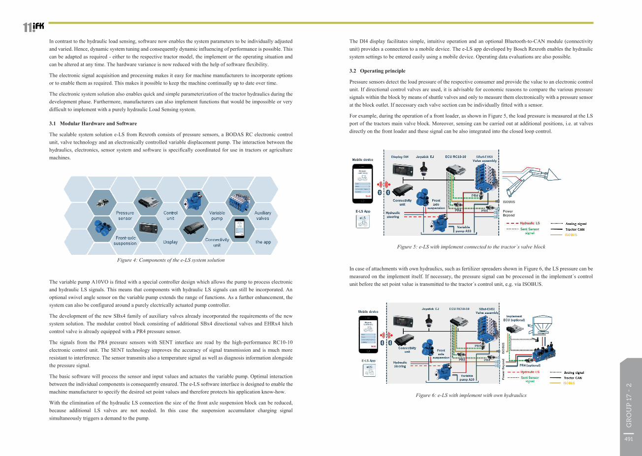
For example, during the operation of a front loader, as shown in Figure 5, the load pressure is measured at the LS port of the tractors main valve block. Moreover, sensing can be carried out at additional positions, i.e. at valves directly on the front loader and these signal can be also integrated into the closed loop control.
Figure 5: e-LS with implement connected to the tractor`s valve block
In case of attachments with own hydraulics, such as fertilizer spreaders shown in Figure 6, the LS pressure can be measured on the implement itself. If necessary, the pressure signal can be processed in the implement´s control unit before the set point value is transmitted to the tractor´s control unit, e.g. via ISOBUS.
Figure 6: e-LS with implement with own hydraulics
The 11th International Fluid Power Conference, 11. IFK, March 19-21, 2018, Aachen, Germany
In contrast to the hydraulic load sensing, software now enables the system parameters to be individually adjusted and varied. Hence, dynamic system tuning and consequently dynamic influencing of performance is possible. This can be adapted as required - either to the respective tractor model, the implement or the operating situation and can be altered at any time. The hardware variance is now reduced with the help of software flexibility.
The electronic signal acquisition and processing makes it easy for machine manufacturers to incorporate options or to enable them as required. This makes it possible to keep the machine continually up to date over time.
The electronic system solution also enables quick and simple parameterization of the tractor hydraulics during the development phase. Furthermore, manufacturers can also implement functions that would be impossible or very difficult to implement with a purely hydraulic Load Sensing system.
3.1 Modular Hardware and Software
The scalable system solution e-LS from Rexroth consists of pressure sensors, a BODAS RC electronic control unit, valve technology and an electronically controlled variable displacement pump. The interaction between the hydraulics, electronics, sensor system and software is specifically coordinated for use in tractors or agriculture machines.
Figure 4: Components of the e-LS system solution
The variable pump A10VO is fitted with a special controller design which allows the pump to process electronic and hydraulic LS signals. This means that components with hydraulic LS signals can still be incorporated. An optional swivel angle sensor on the variable pump extends the range of functions. As a further enhancement, the system can also be configured around a purely electrically actuated pump controller.
The development of the new SBx4 family of auxiliary valves already incorporated the requirements of the new system solution. The modular control block consisting of additional SBx4 directional valves and EHRx4 hitch control valve is already equipped with a PR4 pressure sensor.
The signals from the PR4 pressure sensors with SENT interface are read by the high-performance RC10-10 electronic control unit. The SENT technology improves the accuracy of signal transmission and is much more resistant to interference. The sensor transmits also a temperature signal as well as diagnosis information alongside the pressure signal.
The basic software will process the sensor and input values and actuates the variable pump. Optimal interaction between the individual components is consequently ensured. The e-LS software interface is designed to enable the machine manufacturer to specify the desired set point values and therefore protects his application know-how.
With the elimination of the hydraulic LS connection the size of the front axle suspension block can be reduced, because additional LS valves are not needed. In this case the suspension accumulator charging signal simultaneously triggers a demand to the pump.
491
GR
OU
P 1
7 -
2
The 11th International Fluid Power Conference, 11. IFK, March 19-21, 2018, Aachen, Germany
Further functions are the variation of the dynamic response of the pump and the filtering of pressure signals in order to reduce system oscillations. Both functions will be explained in chapter 4.
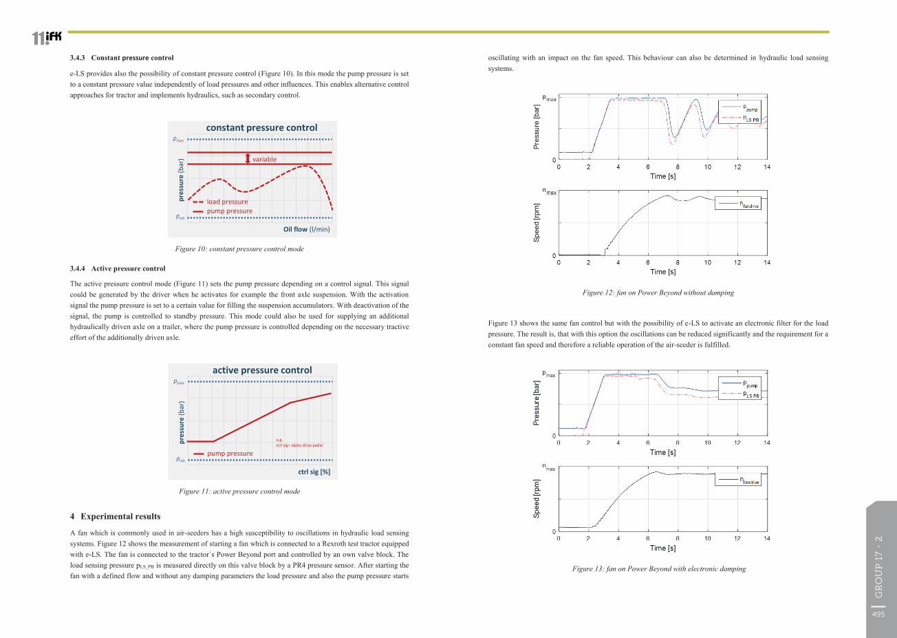
3.4.1 Constant Δp control
The mode constant Δp control (Figure 8) fixes the delta pressure to a constant value throughout the whole flow range. This is the same behaviour as of a hydraulic LS system. However, the level of this constant value is variable and can be changed electronically by parameterization. If, for example an implement on the Power Beyond needs a higher Δp than the tractor provides in normal condition, the Δp setpoint can be adjusted to the needs of the implement in order to optimize the working process and the performance.
Figure 8: constant Δp control mode
3.4.2 Variable Δp control
With the mode variable Δp control (Figure 9) the delta pressure varies according to the flow increasing in line with the quantity of oil. Corresponding system characteristic curves can be individually set up in the electronic control unit, and they may even vary between individual consumers like the main valve block and the Power Beyond port. This enables Δp to be set optimally for the respective hydraulic system. This mode leads to more energy efficiency of the system especially in applications where midrange flows are needed.
Figure 9: variable Δp control mode
Oil flow (l/min)
pres
sure
(bar
)
load pressurepump pressure
constant delta pressure
dp
variable
pstb
pmax
system(Pressure losses)
Oil flow (l/min)
pres
sure
(bar
)
load pressurepump pressure
variable delta pressure
dp
variable
pstb
pmax
system(Pressure losses)
implementEnergy saving
The 11th International Fluid Power Conference, 11. IFK, March 19-21, 2018, Aachen, Germany
If the implement does not provide an electronic pressure signal, the LS interface can be hydraulically connected to the Power Beyond port of the tractor, as is already done today. A pressure sensor on the tractor side converts the hydraulic signal into a digital one. Functions with known or predefined pressure values, such as front axle suspension, do not require a pressure sensor, and the LS tie-in valves which are currently necessary can also be omitted. These pressure values can, if required, be generated on demand in the control unit itself.
All the pressure signals are transmitted to the electronic control unit where they are processed. Various evaluation algorithms are available depending on the operation mode. The conventional procedure is to determine the maximum load pressure and then – with a delta pressure – specify it as a set point value for the pump controller. However, the signal to the pump controller can also be individually adapted to the situation or the operating mode or attachment. An optional swivel angle sensor on the variable pump makes additional functions possible, such as power management or adaptive delta pressure settings.
3.3 From LS to e-LS
With a Rexroth electronified open loop pump, e-LS can be built up as a modular system. Intermediate stages on the road to an all-electronic design continue to allow hydraulic LS signals to be integrated. Consequently, the solution can also be implemented with existing system configurations. For the first step towards an electronified implement hydraulics it is most beneficial to incorporate the directional control valves, the Power Beyond port and the front axle suspension into the basic version of e-LS. This configuration already enables many functions to be realized. At this level, the LS signals from steering and the service brake are still sent to the variable pump hydraulically.
In full extension, the LS signals from all the components are measured electronically by pressure sensors and an electronically pressure-controlled pump without hydraulic LS signal interface is used. This eliminates all the hydraulic LS lines and shuttle valves except for the shuttle valves within the valve block.
3.4 Operating modes and functions
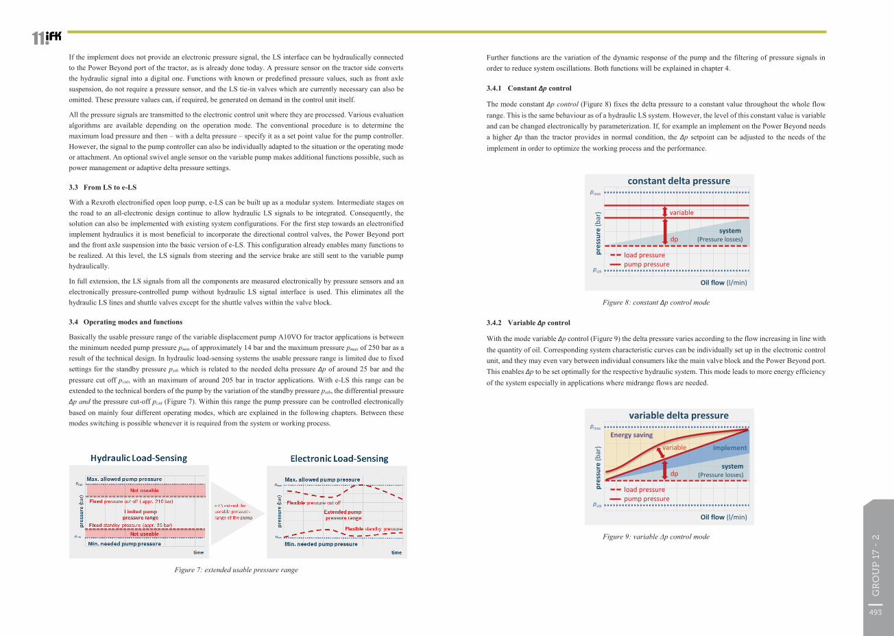
Basically the usable pressure range of the variable displacement pump A10VO for tractor applications is between the minimum needed pump pressure pmin of approximately 14 bar and the maximum pressure pmax of 250 bar as a result of the technical design. In hydraulic load-sensing systems the usable pressure range is limited due to fixed settings for the standby pressure pstb which is related to the needed delta pressure Δp of around 25 bar and the pressure cut off pcut, with an maximum of around 205 bar in tractor applications. With e-LS this range can be extended to the technical borders of the pump by the variation of the standby pressure pstb, the differential pressure Δp and the pressure cut-off pcut (Figure 7). Within this range the pump pressure can be controlled electronically based on mainly four different operating modes, which are explained in the following chapters. Between these modes switching is possible whenever it is required from the system or working process.
Figure 7: extended usable pressure range
493
GR
OU
P 1
7 -
2
The 11th International Fluid Power Conference, 11. IFK, March 19-21, 2018, Aachen, Germany
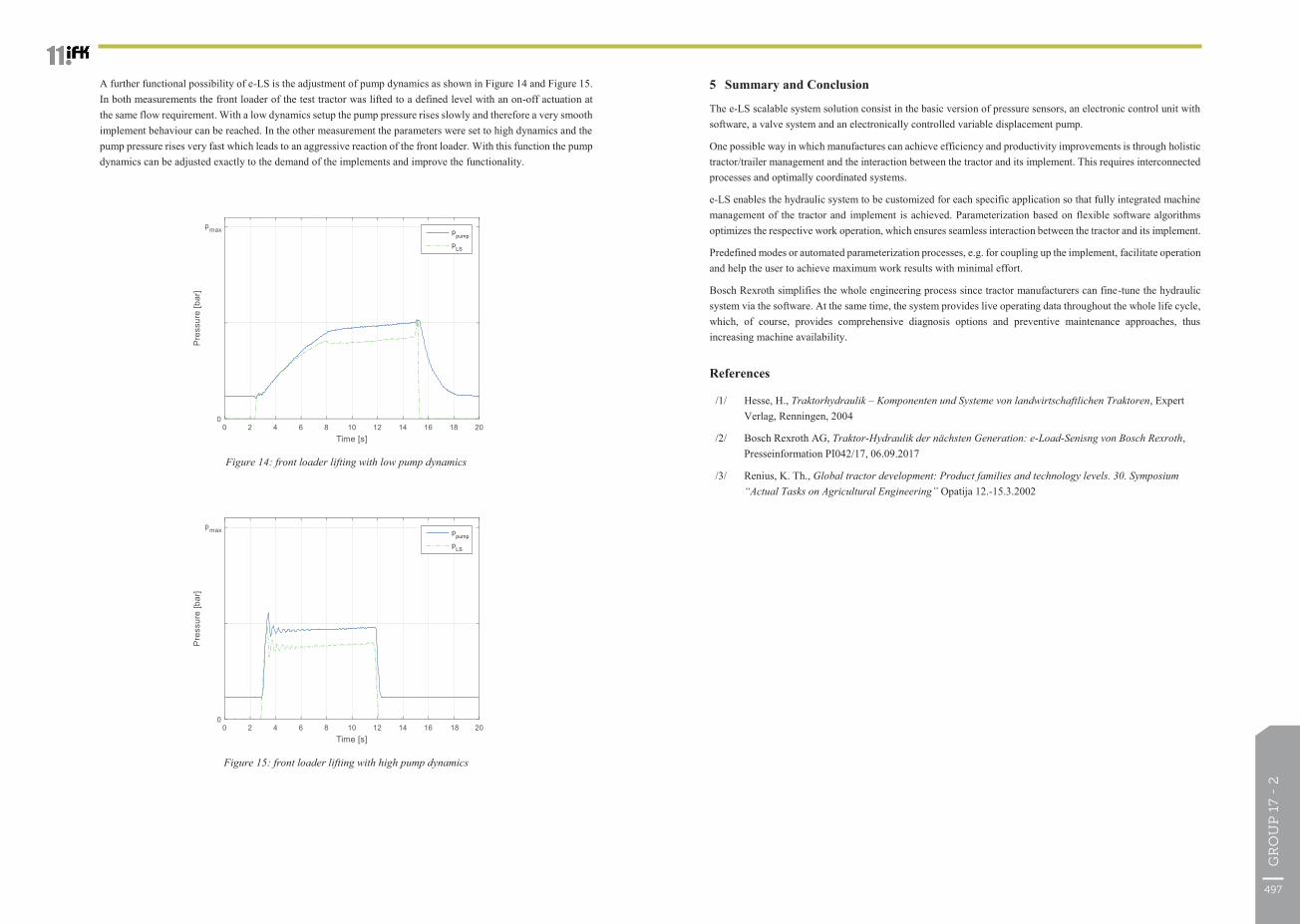
oscillating with an impact on the fan speed. This behaviour can also be determined in hydraulic load sensing systems.
Figure 12: fan on Power Beyond without damping
Figure 13 shows the same fan control but with the possibility of e-LS to activate an electronic filter for the load pressure. The result is, that with this option the oscillations can be reduced significantly and the requirement for a constant fan speed and therefore a reliable operation of the air-seeder is fulfilled.
Figure 13: fan on Power Beyond with electronic damping
The 11th International Fluid Power Conference, 11. IFK, March 19-21, 2018, Aachen, Germany
3.4.3 Constant pressure control
e-LS provides also the possibility of constant pressure control (Figure 10). In this mode the pump pressure is set to a constant pressure value independently of load pressures and other influences. This enables alternative control approaches for tractor and implements hydraulics, such as secondary control.
Figure 10: constant pressure control mode
3.4.4 Active pressure control
The active pressure control mode (Figure 11) sets the pump pressure depending on a control signal. This signal could be generated by the driver when he activates for example the front axle suspension. With the activation signal the pump pressure is set to a certain value for filling the suspension accumulators. With deactivation of the signal, the pump is controlled to standby pressure. This mode could also be used for supplying an additional hydraulically driven axle on a trailer, where the pump pressure is controlled depending on the necessary tractive effort of the additionally driven axle.
Figure 11: active pressure control mode
4 Experimental results
A fan which is commonly used in air-seeders has a high susceptibility to oscillations in hydraulic load sensing systems. Figure 12 shows the measurement of starting a fan which is connected to a Rexroth test tractor equipped with e-LS. The fan is connected to the tractor`s Power Beyond port and controlled by an own valve block. The load sensing pressure pLS_PB is measured directly on this valve block by a PR4 pressure sensor. After starting the fan with a defined flow and without any damping parameters the load pressure and also the pump pressure starts
Oil flow (l/min)
pres
sure
(bar
)
load pressurepump pressure
constant pressure control
variable
pstb
pmax
ctrl sig [%]
pres
sure
(bar
)
pump pressure
active pressure control
pstb
pmax
e.g. ctrl sig= alpha drive pedal
495
GR
OU
P 1
7 -
2
The 11th International Fluid Power Conference, 11. IFK, March 19-21, 2018, Aachen, Germany
5 Summary and Conclusion
The e-LS scalable system solution consist in the basic version of pressure sensors, an electronic control unit with software, a valve system and an electronically controlled variable displacement pump.
One possible way in which manufactures can achieve efficiency and productivity improvements is through holistic tractor/trailer management and the interaction between the tractor and its implement. This requires interconnected processes and optimally coordinated systems.
e-LS enables the hydraulic system to be customized for each specific application so that fully integrated machine management of the tractor and implement is achieved. Parameterization based on flexible software algorithms optimizes the respective work operation, which ensures seamless interaction between the tractor and its implement.
Predefined modes or automated parameterization processes, e.g. for coupling up the implement, facilitate operation and help the user to achieve maximum work results with minimal effort.
Bosch Rexroth simplifies the whole engineering process since tractor manufacturers can fine-tune the hydraulic system via the software. At the same time, the system provides live operating data throughout the whole life cycle, which, of course, provides comprehensive diagnosis options and preventive maintenance approaches, thus increasing machine availability.
References
/1/ Hesse, H., Traktorhydraulik – Komponenten und Systeme von landwirtschaftlichen Traktoren, Expert Verlag, Renningen, 2004
/2/ Bosch Rexroth AG, Traktor-Hydraulik der nächsten Generation: e-Load-Senisng von Bosch Rexroth, Presseinformation PI042/17, 06.09.2017
/3/ Renius, K. Th., Global tractor development: Product families and technology levels. 30. Symposium “Actual Tasks on Agricultural Engineering” Opatija 12.-15.3.2002
The 11th International Fluid Power Conference, 11. IFK, March 19-21, 2018, Aachen, Germany
A further functional possibility of e-LS is the adjustment of pump dynamics as shown in Figure 14 and Figure 15. In both measurements the front loader of the test tractor was lifted to a defined level with an on-off actuation at the same flow requirement. With a low dynamics setup the pump pressure rises slowly and therefore a very smooth implement behaviour can be reached. In the other measurement the parameters were set to high dynamics and the pump pressure rises very fast which leads to an aggressive reaction of the front loader. With this function the pump dynamics can be adjusted exactly to the demand of the implements and improve the functionality.
Figure 14: front loader lifting with low pump dynamics
Figure 15: front loader lifting with high pump dynamics
497
GR
OU
P 1
7 -
2