Embed Size (px)
Citation preview
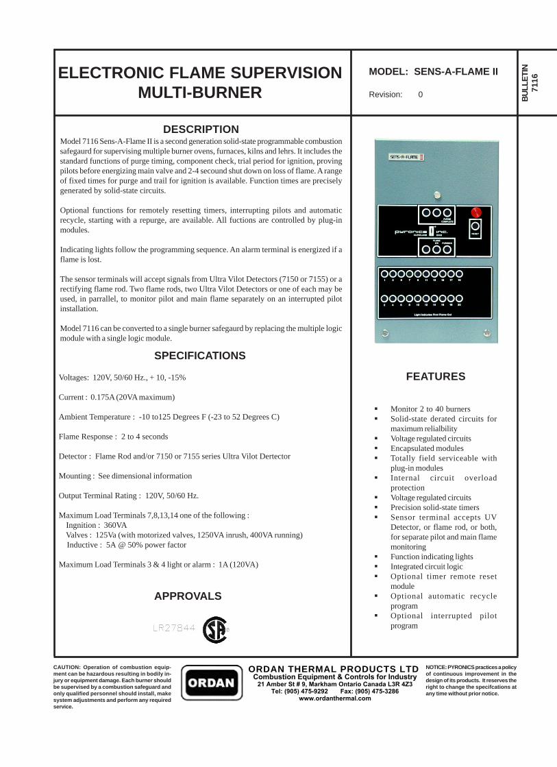
DESCRIPTIONModel 7116 Sens-A-Flame II is a second generation solid-state programmable combustionsafegaurd for supervising multiple burner ovens, furnaces, kilns and lehrs. It includes thestandard functions of purge timing, component check, trial period for ignition, provingpilots before energizing main valve and 2-4 secound shut down on loss of flame. A rangeof fixed times for purge and trail for ignition is available. Function times are preciselygenerated by solid-state circuits.
Optional functions for remotely resetting timers, interrupting pilots and automaticrecycle, starting with a repurge, are available. All fuctions are controlled by plug-inmodules.
Indicating lights follow the programming sequence. An alarm terminal is energized if aflame is lost.
The sensor terminals will accept signals from Ultra Vilot Detectors (7150 or 7155) or arectifying flame rod. Two flame rods, two Ultra Vilot Detectors or one of each may beused, in parrallel, to monitor pilot and main flame separately on an interrupted pilotinstallation.
Model 7116 can be converted to a single burner safegaurd by replacing the multiple logicmodule with a single logic module.
ELECTRONIC FLAME SUPERVISIONMULTI-BURNER
MODEL: SENS-A-FLAME II
Revision: 0 BULL
ETIN
7116
SPECIFICATIONS
Voltages: 120V, 50/60 Hz., + 10, -15%
Current : 0.175A (20VA maximum)
Ambient Temperature : -10 to125 Degrees F (-23 to 52 Degrees C)
Flame Response : 2 to 4 seconds
Detector : Flame Rod and/or 7150 or 7155 series Ultra Vilot Dertector
Mounting : See dimensional information
Output Terminal Rating : 120V, 50/60 Hz.
Maximum Load Terminals 7,8,13,14 one of the following : Ingnition : 360VA Valves : 125Va (with motorized valves, 1250VA inrush, 400VA running) Inductive : 5A @ 50% power factor
Maximum Load Terminals 3 & 4 light or alarm : 1A (120VA)
APPROVALS
Monitor 2 to 40 burnersSolid-state derated circuits formaximum relialbilityVoltage regulated circuitsEncapsulated modulesTotally field serviceable withplug-in modulesInternal circuit overloadprotectionVoltage regulated circuitsPrecision solid-state timersSensor terminal accepts UVDetector, or flame rod, or both,for separate pilot and main flamemonitoringFunction indicating lightsIntegrated circuit logicOptional timer remote resetmoduleOptional automatic recycleprogramOptional interrupted pilotprogram
FEATURES
CAUTION: Operation of combustion equip-ment can be hazardous resulting in bodily in-jury or equipment damage. Each burner shouldbe supervised by a combustion safeguard andonly qualified personnel should install, makesystem adjustments and perform any requiredservice.
NOTICE: PYRONICS practices a policyof continuous improvement in thedesign of its products. It reserves theright to change the specifcations atany time without prior notice.
ORDAN THERMAL PRODUCTS LTDCombustion Equipment & Controls for Industry
21 Amber St # 9, Markham Ontario Canada L3R 4Z3 Tel: (905) 475-9292 Fax: (905) 475-3286
www.ordanthermal.com
ELECTRONIC FLAME SUPERVISION BULLETIN7116
PAGE NO. 2
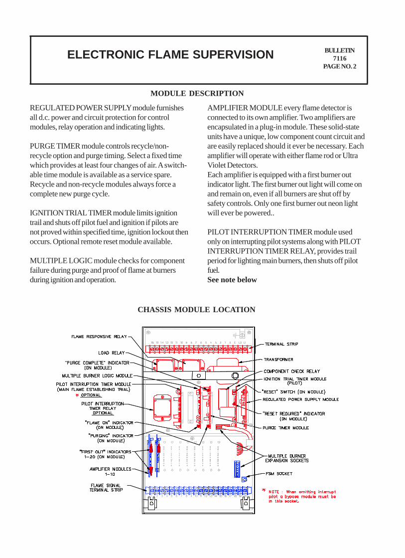
MODULE DESCRIPTION
REGULATED POWER SUPPLY module furnishesall d.c. power and circuit protection for controlmodules, relay operation and indicating lights.
PURGE TIMER module controls recycle/non-recycle option and purge timing. Select a fixed timewhich provides at least four changes of air. A switch-able time module is available as a service spare.Recycle and non-recycle modules always force acomplete new purge cycle.
IGNITION TRIAL TIMER module limits ignitiontrail and shuts off pilot fuel and ignition if pilots arenot proved within specified time, ignition lockout thenoccurs. Optional remote reset module available.
MULTIPLE LOGIC module checks for componentfailure during purge and proof of flame at burnersduring ignition and operation.
AMPLIFIER MODULE every flame detector isconnected to its own amplifier. Two amplifiers areencapsulated in a plug-in module. These solid-stateunits have a unique, low component count circuit andare easily replaced should it ever be necessary. Eachamplifier will operate with either flame rod or UltraViolet Detectors.Each amplifier is equipped with a first burner outindicator light. The first burner out light will come onand remain on, even if all burners are shut off bysafety controls. Only one first burner out neon lightwill ever be powered..
PILOT INTERRUPTION TIMER module usedonly on interrupting pilot systems along with PILOTINTERRUPTION TIMER RELAY, provides trailperiod for lighting main burners, then shuts off pilotfuel.See note below
CHASSIS MODULE LOCATION
ELECTRONIC FLAME SUPERVISION BULLETIN7116
PAGE NO. 3
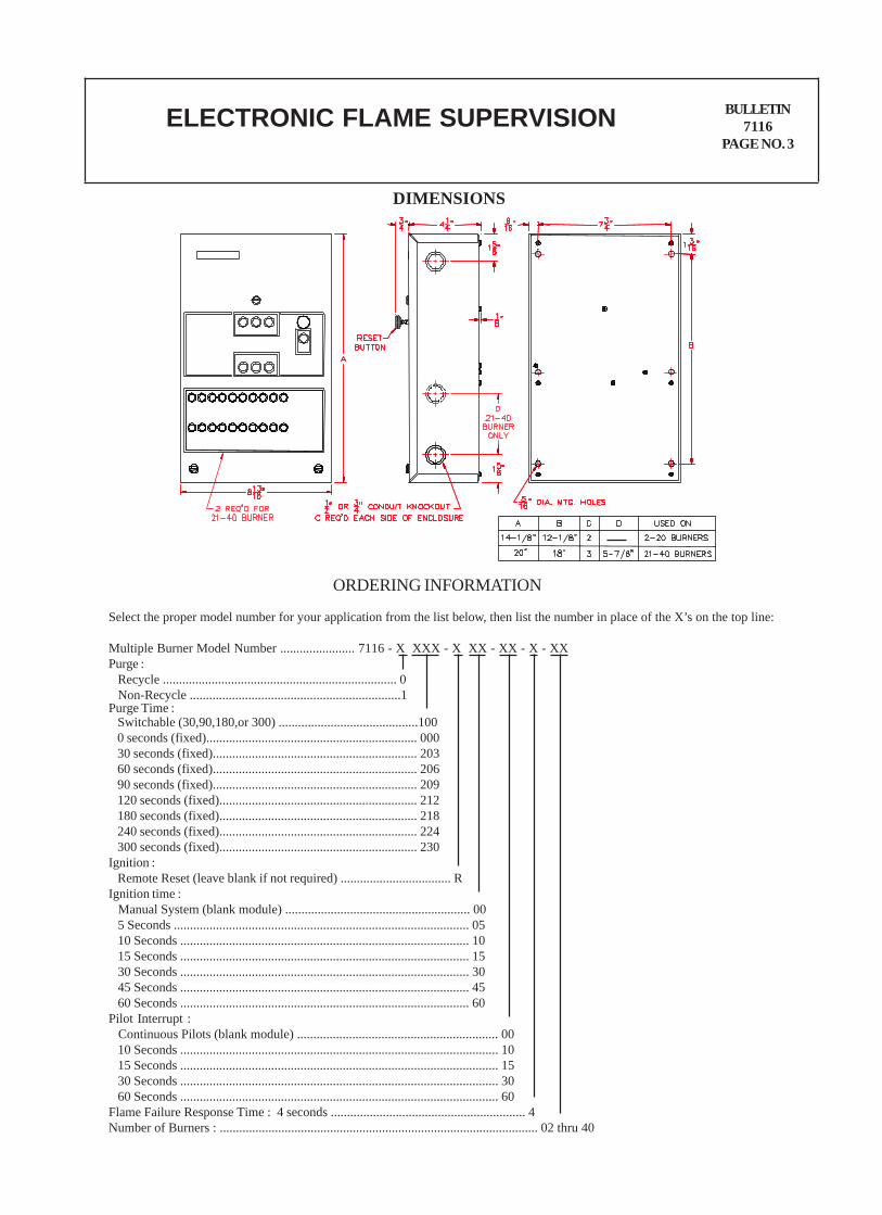
DIMENSIONS
Select the proper model number for your application from the list below, then list the number in place of the X’s on the top line:
Multiple Burner Model Number ....................... 7116 - X XXX - X XX - XX - X - XXPurge : Recycle ........................................................................ 0 Non-Recycle .................................................................1Purge Time : Switchable (30,90,180,or 300) ...........................................100 0 seconds (fixed)................................................................. 000 30 seconds (fixed)............................................................... 203 60 seconds (fixed)............................................................... 206 90 seconds (fixed)............................................................... 209 120 seconds (fixed)............................................................. 212 180 seconds (fixed)............................................................. 218 240 seconds (fixed)............................................................. 224 300 seconds (fixed)............................................................. 230Ignition : Remote Reset (leave blank if not required) .................................. RIgnition time : Manual System (blank module) ......................................................... 00 5 Seconds ........................................................................................... 05 10 Seconds ......................................................................................... 10 15 Seconds ......................................................................................... 15 30 Seconds ......................................................................................... 30 45 Seconds ......................................................................................... 45 60 Seconds ......................................................................................... 60Pilot Interrupt : Continuous Pilots (blank module) .............................................................. 00 10 Seconds .................................................................................................. 10 15 Seconds .................................................................................................. 15 30 Seconds .................................................................................................. 30 60 Seconds .................................................................................................. 60Flame Failure Response Time : 4 seconds ............................................................ 4Number of Burners : .................................................................................................. 02 thru 40
ORDERING INFORMATION
ELECTRONIC FLAME SUPERVISION BULLETIN7116
PAGE NO. 4
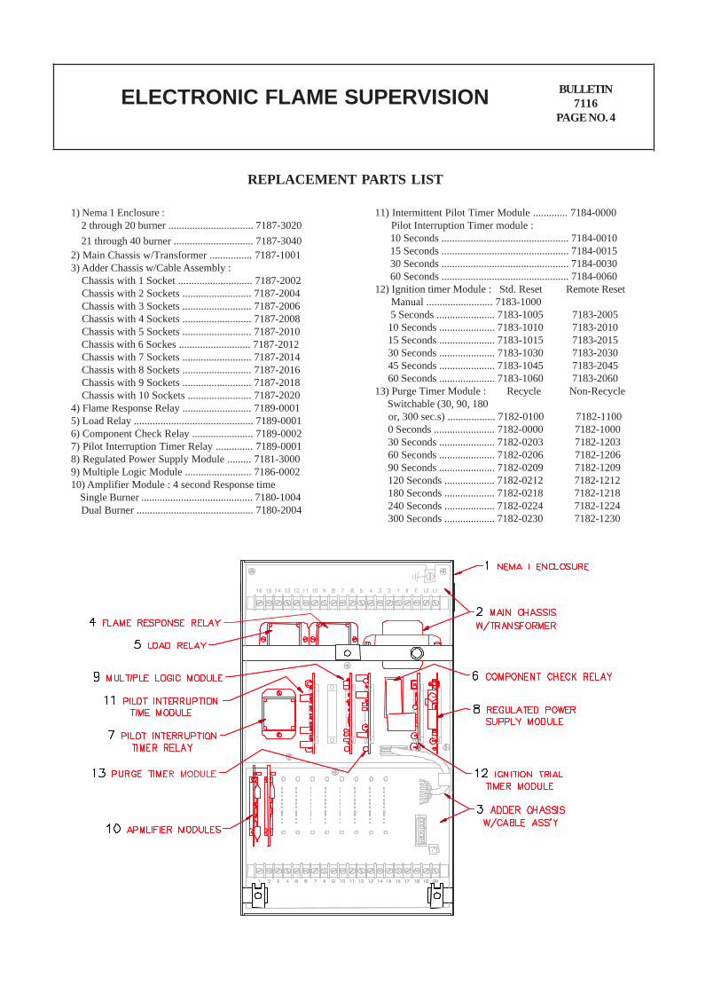
REPLACEMENT PARTS LIST
1) Nema 1 Enclosure : 2 through 20 burner ................................ 7187-3020 21 through 40 burner .............................. 7187-30402) Main Chassis w/Transformer ................ 7187-10013) Adder Chassis w/Cable Assembly : Chassis with 1 Socket ............................ 7187-2002 Chassis with 2 Sockets .......................... 7187-2004 Chassis with 3 Sockets .......................... 7187-2006 Chassis with 4 Sockets .......................... 7187-2008 Chassis with 5 Sockets .......................... 7187-2010 Chassis with 6 Sockes ........................... 7187-2012 Chassis with 7 Sockets .......................... 7187-2014 Chassis with 8 Sockets .......................... 7187-2016 Chassis with 9 Sockets .......................... 7187-2018 Chassis with 10 Sockets ........................ 7187-20204) Flame Response Relay .......................... 7189-00015) Load Relay ............................................. 7189-00016) Component Check Relay ....................... 7189-00027) Pilot Interruption Timer Relay .............. 7189-00018) Regulated Power Supply Module ......... 7181-30009) Multiple Logic Module ......................... 7186-000210) Amplifier Module : 4 second Response time Single Burner .......................................... 7180-1004 Dual Burner ............................................ 7180-2004
11) Intermittent Pilot Timer Module ............. 7184-0000 Pilot Interruption Timer module : 10 Seconds ................................................ 7184-0010 15 Seconds ................................................ 7184-0015 30 Seconds ................................................ 7184-0030 60 Seconds ................................................ 7184-006012) Ignition timer Module : Std. Reset Remote Reset Manual ......................... 7183-1000 5 Seconds ...................... 7183-1005 7183-2005 10 Seconds ..................... 7183-1010 7183-2010 15 Seconds ..................... 7183-1015 7183-2015 30 Seconds ..................... 7183-1030 7183-2030 45 Seconds ..................... 7183-1045 7183-2045 60 Seconds ..................... 7183-1060 7183-206013) Purge Timer Module : Recycle Non-Recycle Switchable (30, 90, 180 or, 300 sec.s) .................. 7182-0100 7182-1100 0 Seconds ....................... 7182-0000 7182-1000 30 Seconds ..................... 7182-0203 7182-1203 60 Seconds ..................... 7182-0206 7182-1206 90 Seconds ..................... 7182-0209 7182-1209 120 Seconds ................... 7182-0212 7182-1212 180 Seconds ................... 7182-0218 7182-1218 240 Seconds ................... 7182-0224 7182-1224 300 Seconds ................... 7182-0230 7182-1230
ELECTRONIC FLAME SUPERVISION BULLETIN7116/7135
PAGE NO. 5
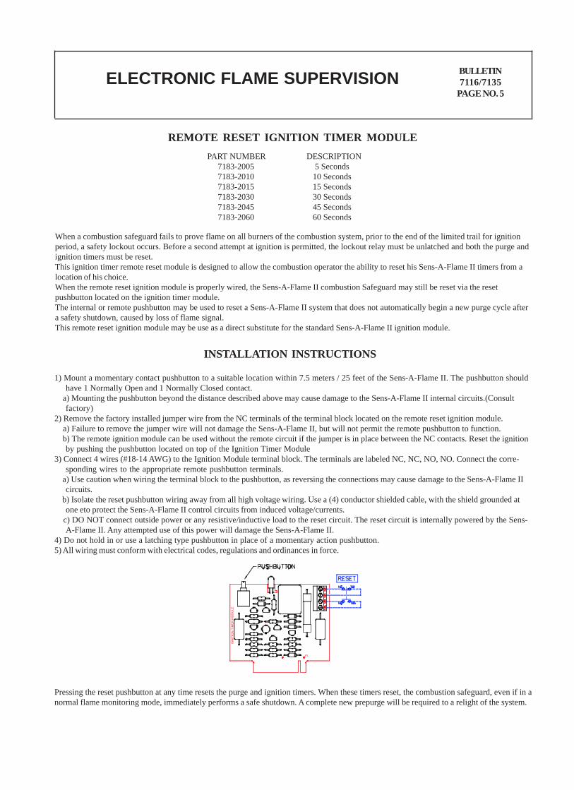
REMOTE RESET IGNITION TIMER MODULEPART NUMBER DESCRIPTION 7183-2005 5 Seconds 7183-2010 10 Seconds 7183-2015 15 Seconds 7183-2030 30 Seconds 7183-2045 45 Seconds 7183-2060 60 Seconds
When a combustion safeguard fails to prove flame on all burners of the combustion system, prior to the end of the limited trail for ignitionperiod, a safety lockout occurs. Before a second attempt at ignition is permitted, the lockout relay must be unlatched and both the purge andignition timers must be reset.This ignition timer remote reset module is designed to allow the combustion operator the ability to reset his Sens-A-Flame II timers from alocation of his choice.When the remote reset ignition module is properly wired, the Sens-A-Flame II combustion Safeguard may still be reset via the resetpushbutton located on the ignition timer module.The internal or remote pushbutton may be used to reset a Sens-A-Flame II system that does not automatically begin a new purge cycle aftera safety shutdown, caused by loss of flame signal.This remote reset ignition module may be use as a direct substitute for the standard Sens-A-Flame II ignition module.
INSTALLATION INSTRUCTIONS
1) Mount a momentary contact pushbutton to a suitable location within 7.5 meters / 25 feet of the Sens-A-Flame II. The pushbutton shouldhave 1 Normally Open and 1 Normally Closed contact.
a) Mounting the pushbutton beyond the distance described above may cause damage to the Sens-A-Flame II internal circuits.(Consultfactory)
2) Remove the factory installed jumper wire from the NC terminals of the terminal block located on the remote reset ignition module. a) Failure to remove the jumper wire will not damage the Sens-A-Flame II, but will not permit the remote pushbutton to function. b) The remote ignition module can be used without the remote circuit if the jumper is in place between the NC contacts. Reset the ignition
by pushing the pushbutton located on top of the Ignition Timer Module3) Connect 4 wires (#18-14 AWG) to the Ignition Module terminal block. The terminals are labeled NC, NC, NO, NO. Connect the corre-
sponding wires to the appropriate remote pushbutton terminals. a) Use caution when wiring the terminal block to the pushbutton, as reversing the connections may cause damage to the Sens-A-Flame II
circuits. b) Isolate the reset pushbutton wiring away from all high voltage wiring. Use a (4) conductor shielded cable, with the shield grounded at
one eto protect the Sens-A-Flame II control circuits from induced voltage/currents. c) DO NOT connect outside power or any resistive/inductive load to the reset circuit. The reset circuit is internally powered by the Sens-
A-Flame II. Any attempted use of this power will damage the Sens-A-Flame II.4) Do not hold in or use a latching type pushbutton in place of a momentary action pushbutton.5) All wiring must conform with electrical codes, regulations and ordinances in force.
Pressing the reset pushbutton at any time resets the purge and ignition timers. When these timers reset, the combustion safeguard, even if in anormal flame monitoring mode, immediately performs a safe shutdown. A complete new prepurge will be required to a relight of the system.
+
P1
IGN
ITIO
N T
IME
R M
OD
ULE
ELECTRONIC FLAME SUPERVISION BULLETIN7116/7135
PAGE NO. 6
REGULATED POWER SUPPLY MODULE FUCTION
PURGE TIMER MODULE FUNCTION
IGNITION TRAIL TIMER MODULE FUNCTION
SINGLE LOGIC/AMPLIFIER MODULE FUNCTION
MULTIPULE LOGIC MODULE FUNCTION
MULTIPLE BURNER AMPLIFIER MODULE FUNTION
PILOT INTERRUPTION TIMER MODULE FUNCTION
Provides regulated -24 volts for logic circuits, solid state amplifiers and relay operation. This supply is protected against short circuit andexcessive ambient temperature. A second -24 volt supply, connected to terminal 1, provides power, through external switches to initiateignition and optional interrupted pilot timing circuits. This supply is protected by a fuse. NOTE : 30 VAC for flame rods and 270 VAC forUV detectors is supplied directly from the transformer.
Models are available providing purge periods from 0 seconds to 5 minutes. The optional recycling function, starting with a second purgeperiod, is determined by the circuits on the purge module. When purge timing is complete and component check is proved, the componentcheck relay closes. A purging light and a purge complete light are mounted on this module. If a flame or a circuit failure, simulating flame, issensed during purge (component check not proved) the purging light will go off, on non-recycle purge modules the system will lock out.After correcting fault, press reset button to recycle. Recycle purge modules will automatically begin a new purge cycle once the fault iscorrected.
The trail period for ignition is precisely timed by this module and should be selected according to code requirements. Ignition is started bymomentary closing of the circuit between terminals 1 and 5, provided component check has been completed. A jumper between terminal 1and 5 will provide automatic ignition. Pilot valves are opened when ignition is started. Ignition will be interrupted by operation of flameresponse relay, when all pilots are proven. Failure to prove pilots within trail period will sound alarm and lock out system. The resetrequired light will be illuminated. Pressing the reset button will recycle the system. Optional remote timer reset module available. (See page 5for details)
This module plugs into the logic cicuitry socket for single burner applications. A sensor current of 1 micro amp (minimum) will prove flameand result in the flame response relay closing, energizing terminal 8 (main fuel valve) and Flame On light. Logic functions are the same asdescribed for the multiple logic module below.
During purge, sensing a flame or flame simulating failure will energize the flame responsive relay and lock out the system. The purging lightwill go off and the Flame On light will light. When no flame is sensed during purging, and trail for ignition has started, the logic module checksfor flame proof at every burner. Upon sensing flame at all burners, the flame responsive relay closes, energizes terminal 8 (main fuel valve)and Flame On light.
These amplifiers, one for each burner, are packaged two to a module. To accommodate an odd number of burners, the last module will containa single amplifier. A module containing a single amplifier is identified by electronic components on one half of the module only.
Sockets for a Pilot Interruption module and the Pilot Interruption relay are on all chassis but the function is optional. Typically, a normallyclosed auxiliary switch on the main fuel valve is used to interrupt a circuit between terminals 1 and 12, starting the timing function. Atcompletion of timing, power is removed from the interrupted pilot terminal.
ELECTRONIC FLAME SUPERVISION BULLETIN7116/7135
PAGE NO. 7
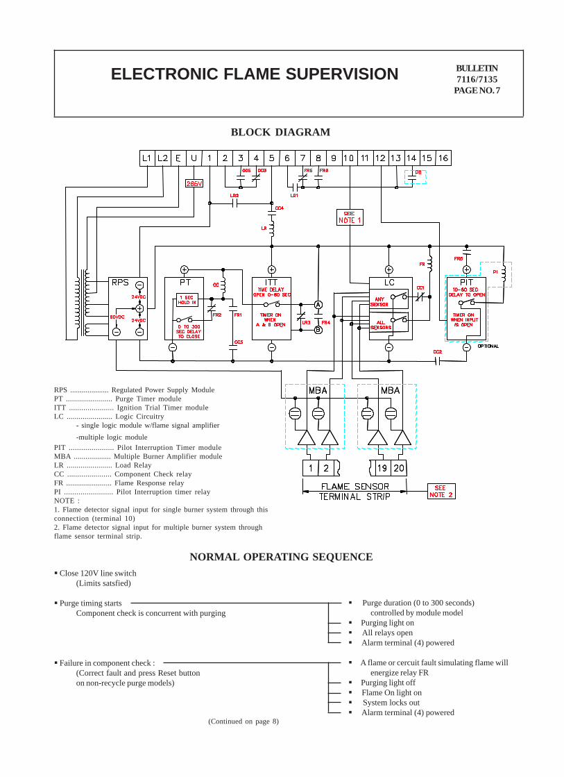
BLOCK DIAGRAM
NORMAL OPERATING SEQUENCE Close 120V line switch
(Limits satsfied)
Purge timing startsComponent check is concurrent with purging
Failure in component check :(Correct fault and press Reset buttonon non-recycle purge models)
Purge duration (0 to 300 seconds)controlled by module model
Purging light on All relays open Alarm terminal (4) powered
A flame or cercuit fault simulating flame willenergize relay FR
Purging light off Flame On light on System locks out Alarm terminal (4) powered
(Continued on page 8)
RPS .................... Regulated Power Supply ModulePT ....................... Purge Timer moduleITT ...................... Ignition Trial Timer moduleLC ....................... Logic Circuitry
- single logic module w/flame signal amplifier-multiple logic module
PIT ...................... Pilot Interruption Timer moduleMBA ................... Multiple Burner Amplifier moduleLR ....................... Load RelayCC ...................... Component Check relayFR ....................... Flame Response relayPI ........................ Pilot Interruption timer relayNOTE :1. Flame detector signal input for single burner system through thisconnection (terminal 10)2. Flame detector signal input for multiple burner system throughflame sensor terminal strip.
ELECTRONIC FLAME SUPERVISION BULLETIN7116/7135
PAGE NO. 8
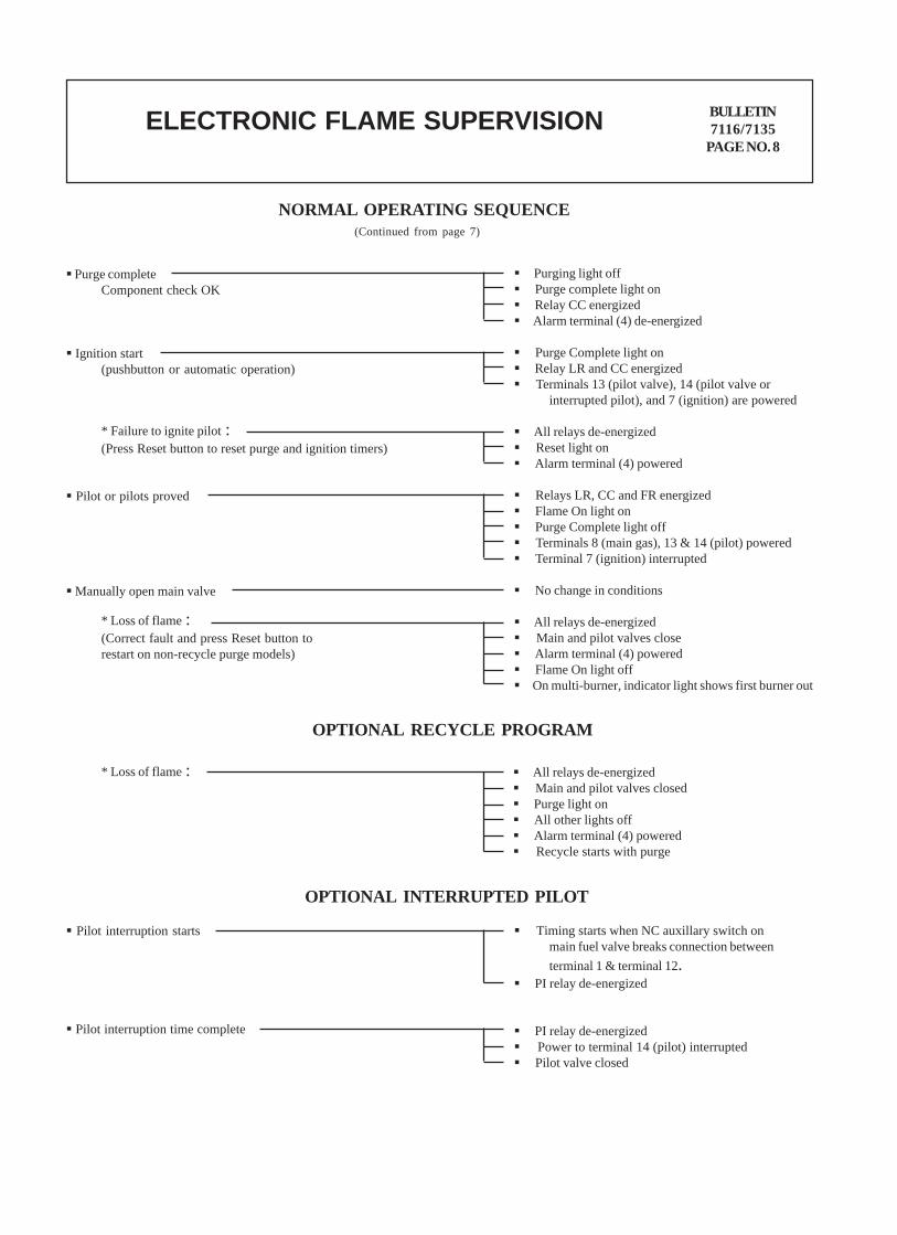
NORMAL OPERATING SEQUENCE(Continued from page 7)
Purge completeComponent check OK
Ignition start(pushbutton or automatic operation)
Purging light off Purge complete light on Relay CC energized Alarm terminal (4) de-energized
Purge Complete light on Relay LR and CC energized Terminals 13 (pilot valve), 14 (pilot valve or
interrupted pilot), and 7 (ignition) are powered
All relays de-energized Reset light on Alarm terminal (4) powered
Relays LR, CC and FR energized Flame On light on Purge Complete light off Terminals 8 (main gas), 13 & 14 (pilot) powered Terminal 7 (ignition) interrupted
No change in conditions
All relays de-energized Main and pilot valves close Alarm terminal (4) powered Flame On light off On multi-burner, indicator light shows first burner out
* Failure to ignite pilot :(Press Reset button to reset purge and ignition timers)
Pilot or pilots proved
Manually open main valve
OPTIONAL RECYCLE PROGRAM
* Loss of flame :(Correct fault and press Reset button torestart on non-recycle purge models)
* Loss of flame : All relays de-energized Main and pilot valves closed Purge light on All other lights off Alarm terminal (4) powered Recycle starts with purge
OPTIONAL INTERRUPTED PILOT
Pilot interruption starts Timing starts when NC auxillary switch onmain fuel valve breaks connection betweenterminal 1 & terminal 12.
PI relay de-energized
PI relay de-energized Power to terminal 14 (pilot) interrupted Pilot valve closed
Pilot interruption time complete
BULLETIN7116/7135
PAGE NO. 9ELECTRONIC FLAME SUPERVISION
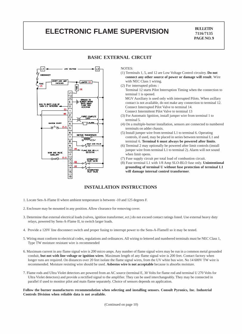
BASIC EXTERNAL CIRCUIT
NOTES:(1) Terminals 1, 5, and 12 are Low Voltage Control circuitry. Do not
connect any other source of power or damage will result. Wirewith NEC Class 1 wiring.
(2) For interrupted pilots : Terminal 12 starts Pilot Interruption Timing when the connection to
terminal 1 is opened. MGV Auxiliary is used only with interrupted Pilots. When axillary
contact is not available, do not make any connection to terminal 12. Connect Interrupted Pilot Valve to terminal 14. Connect Intermittent Pilot Valve to terminal 13(3) For Automatic Ignition, install jumper wire from terminal 1 to
terminal 5.(4) On a multiple-burner installation, sensors are connected to numbered
terminals on adder chassis.(5) Install jumper wire from terminal L1 to terminal 6. Operating
controls, if used, may be placed in series between terminal L1 andterminal 6. Terminal 6 must always be powered after limits.
(6) Terminal 2 may optionally be powered after limit controls (installjumper wire from terminal L1 to terminal 2). Alarm will not soundwhen limit opens.
(7) Fuse supply circuit per total load of combustion circuit.(8) Fuse terminal L1 with 1/8 Amp SLO-BLO fuse only. Unintentional
grounding of terminal U without fuse protection of terminal L1will damage internal control transformer.
INSTALLATION INSTRUCTIONS
1. Locate Sen-A-Flame II where ambient temperature is between -10 and 125 degrees F.
2. Enclosure may be mounted in any position. Allow clearance for removing cover.
3. Determine that external electrical loads (valves, ignition transformer, ect.) do not exceed contact ratings listed. Use external heavy dutyrelays, powered by Sens-A-Flame II, to switch larger loads.
4. Provide a 120V line disconnect switch and proper fusing to interrupt power to the Sens-A-FlameII so it may be tested.
5. Wiring must conform to electrical codes, regulations and ordinances. All wiring to lettered and numbered terminals must be NEC Class 1,Type TW moisture resistant wire is recommended
6. Maximum current in any flame signal wire is 200 micro amps. Any number of flame signal wires may be run in a common metal groundedconduit, but not with line voltage or ignition wires. Maximum length of any flame signal wire is 200 feet. Contact factory whenlonger runs are required. On distances over 20 feet isolate the flame signal wires, from the UV white bus wire. No 14 600V TW wire isrecommended. Moisture resisting wire should be used. Asbestos wire is not acceptable because is absorbs moisture.
7. Flame rods and Ultra Violet detectors are powered from an AC source (terminal E, 30 Volts for flame rod and terminal U 270 Volts forUltra Violet detectors) and provide a rectified signal to the amplifier. They can be used interchangeably. They may be connected inparallel if used to monitor pilot and main flame separately. Choice of sensors depends on application.
Follow the burner manufactures recommendation when selecting and installing sensors. Consult Pyronics, Inc. IndustrialControls Division when reliable data is not available.
(Continued on page 10)
ELECTRONIC FLAME SUPERVISION BULLETIN7116/7135
PAGE NO. 10
INSTALLATION INSTRUCTIONS(Continued from page 9)
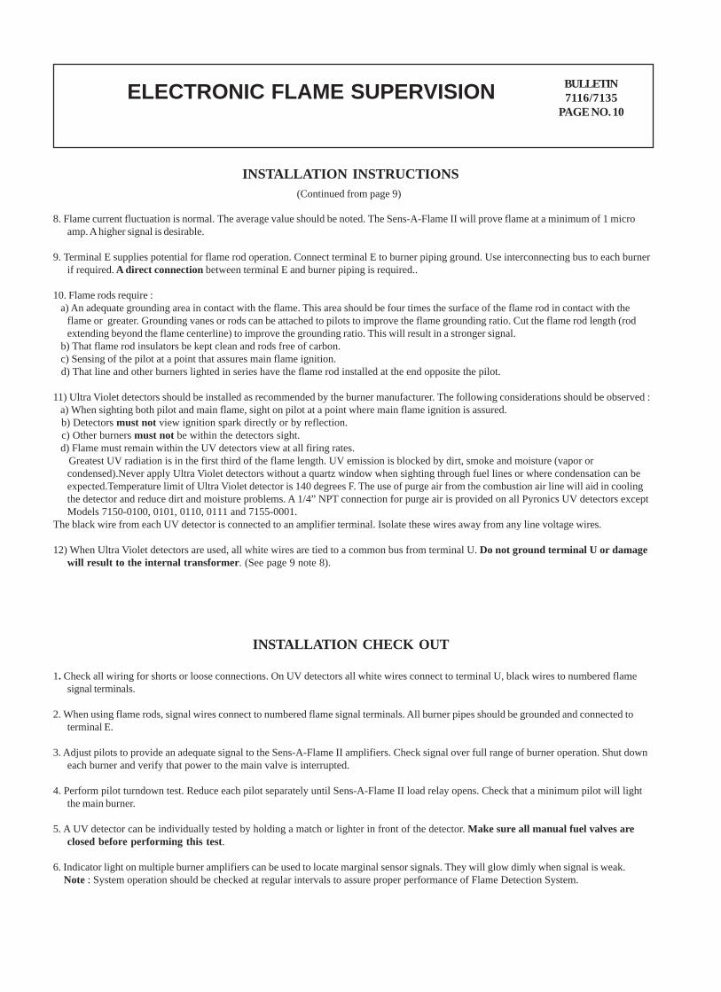
8. Flame current fluctuation is normal. The average value should be noted. The Sens-A-Flame II will prove flame at a minimum of 1 microamp. A higher signal is desirable.
9. Terminal E supplies potential for flame rod operation. Connect terminal E to burner piping ground. Use interconnecting bus to each burnerif required. A direct connection between terminal E and burner piping is required..
10. Flame rods require : a) An adequate grounding area in contact with the flame. This area should be four times the surface of the flame rod in contact with the
flame or greater. Grounding vanes or rods can be attached to pilots to improve the flame grounding ratio. Cut the flame rod length (rodextending beyond the flame centerline) to improve the grounding ratio. This will result in a stronger signal.
b) That flame rod insulators be kept clean and rods free of carbon. c) Sensing of the pilot at a point that assures main flame ignition. d) That line and other burners lighted in series have the flame rod installed at the end opposite the pilot.
11) Ultra Violet detectors should be installed as recommended by the burner manufacturer. The following considerations should be observed : a) When sighting both pilot and main flame, sight on pilot at a point where main flame ignition is assured. b) Detectors must not view ignition spark directly or by reflection. c) Other burners must not be within the detectors sight. d) Flame must remain within the UV detectors view at all firing rates. Greatest UV radiation is in the first third of the flame length. UV emission is blocked by dirt, smoke and moisture (vapor or
condensed).Never apply Ultra Violet detectors without a quartz window when sighting through fuel lines or where condensation can beexpected.Temperature limit of Ultra Violet detector is 140 degrees F. The use of purge air from the combustion air line will aid in coolingthe detector and reduce dirt and moisture problems. A 1/4” NPT connection for purge air is provided on all Pyronics UV detectors exceptModels 7150-0100, 0101, 0110, 0111 and 7155-0001.
The black wire from each UV detector is connected to an amplifier terminal. Isolate these wires away from any line voltage wires.
12) When Ultra Violet detectors are used, all white wires are tied to a common bus from terminal U. Do not ground terminal U or damagewill result to the internal transformer. (See page 9 note 8).
INSTALLATION CHECK OUT
1. Check all wiring for shorts or loose connections. On UV detectors all white wires connect to terminal U, black wires to numbered flamesignal terminals.
2. When using flame rods, signal wires connect to numbered flame signal terminals. All burner pipes should be grounded and connected toterminal E.
3. Adjust pilots to provide an adequate signal to the Sens-A-Flame II amplifiers. Check signal over full range of burner operation. Shut downeach burner and verify that power to the main valve is interrupted.
4. Perform pilot turndown test. Reduce each pilot separately until Sens-A-Flame II load relay opens. Check that a minimum pilot will lightthe main burner.
5. A UV detector can be individually tested by holding a match or lighter in front of the detector. Make sure all manual fuel valves areclosed before performing this test.
6. Indicator light on multiple burner amplifiers can be used to locate marginal sensor signals. They will glow dimly when signal is weak. Note : System operation should be checked at regular intervals to assure proper performance of Flame Detection System.
BULLETIN7116/7135
PAGE NO. 11ELECTRONIC FLAME SUPERVISION
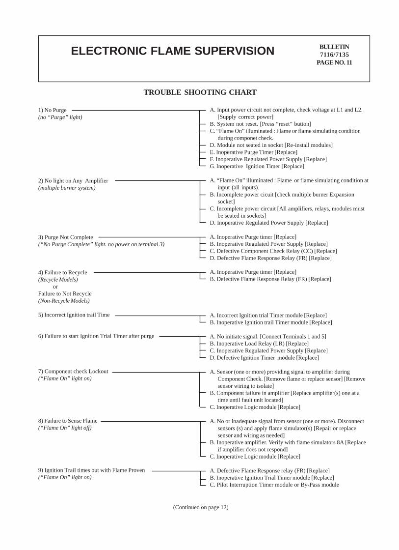
TROUBLE SHOOTING CHART
1) No Purge(no “Purge” light)
2) No light on Any Amplifier(multiple burner system)
3) Purge Not Complete(“No Purge Complete” light. no power on terminal 3)
4) Failure to Recycle(Recycle Models) orFailure to Not Recycle(Non-Recycle Models)
5) Incorrect Ignition trail Time
6) Failure to start Ignition Trial Timer after purge
7) Component check Lockout(“Flame On” light on)
8) Failure to Sense Flame(“Flame On” light off)
9) Ignition Trail times out with Flame Proven(“Flame On” light on)
A. Input power circuit not complete, check voltage at L1 and L2.[Supply correct power]
B. System not reset. [Press “reset” button]C. “Flame On” illuminated : Flame or flame simulating condition
during componet check.D. Module not seated in socket [Re-install modules]E. Inoperative Purge Timer [Replace]F. Inoperative Regulated Power Supply [Replace]G. Inoperative Ignition Timer [Replace]
A. “Flame On” illuminated : Flame or flame simulating condition atinput (all inputs).
B. Incomplete power cicuit [check multiple burner Expansionsocket]
C. Incomplete power circuit [All amplifiers, relays, modules mustbe seated in sockets]
D. Inoperative Regulated Power Supply [Replace]
A. Inoperative Purge timer [Replace]B. Inoperative Regulated Power Supply [Replace]C. Defective Component Check Relay (CC) [Replace]D. Defective Flame Response Relay (FR) [Replace]
A. Incorrect Ignition trial Timer module [Replace]B. Inoperative Ignition trail Timer module [Replace]
A. No initiate signal. [Connect Terminals 1 and 5]B. Inoperative Load Relay (LR) [Replace]C. Inoperative Regulated Power Supply [Replace]D. Defective Ignition Timer module [Replace]
A. Sensor (one or more) providing signal to amplifier duringComponent Check. [Remove flame or replace sensor] [Removesensor wiring to isolate]
B. Component failure in amplifier [Replace amplifier(s) one at atime until fault unit located]
C. Inoperative Logic module [Replace]
A. No or inadequate signal from sensor (one or more). Disconnectsensors (s) and apply flame simulator(s) [Repair or replacesensor and wiring as needed]
B. Inoperative amplifier. Verify with flame simulators 8A [Replaceif amplifier does not respond]
C. Inoperative Logic module [Replace]
A. Defective Flame Response relay (FR) [Replace]B. Inoperative Ignition Trial Timer module [Replace]C. Pilot Interruption Timer module or By-Pass module
A. Inoperative Purge timer [Replace]B. Defective Flame Response Relay (FR) [Replace]
(Continued on page 12)
ELECTRONIC FLAME SUPERVISION BULLETIN7116/7135
PAGE NO. 12
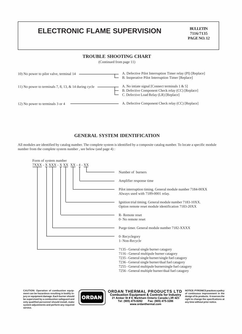
TROUBLE SHOOTING CHART
10) No power to pilot valve, terminal 14
11) No power to terminals 7, 8, 13, & 14 during cycle
12) No power to terminals 3 or 4
(Continued from page 11)
A. Defective Pilot Interruption Timer relay (PI) [Replace]B. Inoperative Pilot Interruption Timer [Replace]
A. No intiate signal [Connect terminals 1 & 5]B. Defective Component Check relay (CC) [Replace]C. Defective Load Relay (LR) [Replace]
A. Defective Component Check relay (CC) [Replace]
GENERAL SYSTEM IDENTIFICATION
All modules are identified by catalog number. The complete system is identified by a composite catalog number. To locate a specific modulenumber from the complete system number , see below (and page 4) :
Form of system number7XXX - X XXX - X XX XX - 4 - XX
Number of burners
Amplifier response time
Pilot interruption timing. General module number 7184-00XXAlways used with 7189-0001 relay.
Ignition trial timing. General module number 7183-10XX.Option remote reset module identification 7183-20XX
R- Remote reset0- No remote reset
Purge timer. General module number 7182-XXXX
0- Recyclegory1- Non-Recycle
7135 - General single burner catagory7116 - General multipule burner catagory7235 - General single burner/single fuel catagory7236 - General single burner/dual fuel catagory7255 - General multipule burnersingle fuel catagory7256 - General multiple burner/dual fuel catagory
CAUTION: Operation of combustion equip-ment can be hazardous resulting in bodily in-jury or equipment damage. Each burner shouldbe supervised by a combustion safeguard andonly qualified personnel should install, makesystem adjustments and perform any requiredservice.
NOTICE: PYRONICS practices a policyof continuous improvement in thedesign of its products. It reserves theright to change the specifcations atany time without prior notice.
ORDAN THERMAL PRODUCTS LTDCombustion Equipment & Controls for Industry
21 Amber St # 9, Markham Ontario Canada L3R 4Z3 Tel: (905) 475-9292 Fax: (905) 475-3286
www.ordanthermal.com