Embed Size (px)
Citation preview
Operation manual
and
installation instructions
Copyr ight © 2013 Vetus b.v. Schiedam Hol land
Electronic engine remote control
ENGLISH
EC3 EC4

2 030624.12 vetus® Electronic engine remote control
Contents1 Introduction . . . . . . . . . . . . . . . . . . . . . . . . . . . . . . . . . . . . . . . . . . . . . . . . . . . . . . . . . . . . . . . . . . . . . . . . . . . . . . . . . . . . . . . . . 5
2 General installation features . . . . . . . . . . . . . . . . . . . . . . . . . . . . . . . . . . . . . . . . . . . . . . . . . . . . . . . . . . . . . . . . . . . . . . . . . 5
2.1 Description of the system without trolling option and its parts . . . . . . . . . . . . . . . . . . . . . . . . . . . . . . . . . . 52.2 Description of the system with trolling option and its parts . . . . . . . . . . . . . . . . . . . . . . . . . . . . . . . . . . . . . . 52.3 Trolling option in combination with Flap option . . . . . . . . . . . . . . . . . . . . . . . . . . . . . . . . . . . . . . . . . . . . . . . . . 52.4 Maximum extension of the system . . . . . . . . . . . . . . . . . . . . . . . . . . . . . . . . . . . . . . . . . . . . . . . . . . . . . . . . . . . . . . 52.5 System performance . . . . . . . . . . . . . . . . . . . . . . . . . . . . . . . . . . . . . . . . . . . . . . . . . . . . . . . . . . . . . . . . . . . . . . . . . . . 6
3 Pilot instructions . . . . . . . . . . . . . . . . . . . . . . . . . . . . . . . . . . . . . . . . . . . . . . . . . . . . . . . . . . . . . . . . . . . . . . . . . . . . . . . . . . . . 7
3.1 Pilot instructions with trolling option . . . . . . . . . . . . . . . . . . . . . . . . . . . . . . . . . . . . . . . . . . . . . . . . . . . . . . . . . . . 83.2 Lever functionality without trolling . . . . . . . . . . . . . . . . . . . . . . . . . . . . . . . . . . . . . . . . . . . . . . . . . . . . . . . . . . . . . 83.3 Lever functionality with trolling enabled . . . . . . . . . . . . . . . . . . . . . . . . . . . . . . . . . . . . . . . . . . . . . . . . . . . . . . . . 83.4 Control keypad . . . . . . . . . . . . . . . . . . . . . . . . . . . . . . . . . . . . . . . . . . . . . . . . . . . . . . . . . . . . . . . . . . . . . . . . . . . . . . . . 93.5 Acquisition of the command. . . . . . . . . . . . . . . . . . . . . . . . . . . . . . . . . . . . . . . . . . . . . . . . . . . . . . . . . . . . . . . . . . . 103.6 Engine Warm-up . . . . . . . . . . . . . . . . . . . . . . . . . . . . . . . . . . . . . . . . . . . . . . . . . . . . . . . . . . . . . . . . . . . . . . . . . . . . . . 103.7 Synchro mode . . . . . . . . . . . . . . . . . . . . . . . . . . . . . . . . . . . . . . . . . . . . . . . . . . . . . . . . . . . . . . . . . . . . . . . . . . . . . . . . 113.8 Trolling mode . . . . . . . . . . . . . . . . . . . . . . . . . . . . . . . . . . . . . . . . . . . . . . . . . . . . . . . . . . . . . . . . . . . . . . . . . . . . . . . . . 113.9 Signals indicating that the system is in Trolling mode . . . . . . . . . . . . . . . . . . . . . . . . . . . . . . . . . . . . . . . . . . . 113.10 Fast Start-up Mode . . . . . . . . . . . . . . . . . . . . . . . . . . . . . . . . . . . . . . . . . . . . . . . . . . . . . . . . . . . . . . . . . . . . . . . . . . . . 113.11 Emergency lever . . . . . . . . . . . . . . . . . . . . . . . . . . . . . . . . . . . . . . . . . . . . . . . . . . . . . . . . . . . . . . . . . . . . . . . . . . . . . . 11
4 Command station . . . . . . . . . . . . . . . . . . . . . . . . . . . . . . . . . . . . . . . . . . . . . . . . . . . . . . . . . . . . . . . . . . . . . . . . . . . . . . . . . . 12
4.1 Dimensions . . . . . . . . . . . . . . . . . . . . . . . . . . . . . . . . . . . . . . . . . . . . . . . . . . . . . . . . . . . . . . . . . . . . . . . . . . . . . . . . . . 124.1.1 Command station EC3 . . . . . . . . . . . . . . . . . . . . . . . . . . . . . . . . . . . . . . . . . . . . . . . . . . . . . . . . . . . . . . . . 124.1.2 Command station EC4 . . . . . . . . . . . . . . . . . . . . . . . . . . . . . . . . . . . . . . . . . . . . . . . . . . . . . . . . . . . . . . . . 12
4.2 Friction adjustment . . . . . . . . . . . . . . . . . . . . . . . . . . . . . . . . . . . . . . . . . . . . . . . . . . . . . . . . . . . . . . . . . . . . . . . . . . . 134.2.1 Command station EC3 . . . . . . . . . . . . . . . . . . . . . . . . . . . . . . . . . . . . . . . . . . . . . . . . . . . . . . . . . . . . . . . . 134.2.2 Command station EC4 . . . . . . . . . . . . . . . . . . . . . . . . . . . . . . . . . . . . . . . . . . . . . . . . . . . . . . . . . . . . . . . . 13
4.3 Programming of the command station . . . . . . . . . . . . . . . . . . . . . . . . . . . . . . . . . . . . . . . . . . . . . . . . . . . . . . . . 144.4 Command station label . . . . . . . . . . . . . . . . . . . . . . . . . . . . . . . . . . . . . . . . . . . . . . . . . . . . . . . . . . . . . . . . . . . . . . . . 144.5 Command station codes. . . . . . . . . . . . . . . . . . . . . . . . . . . . . . . . . . . . . . . . . . . . . . . . . . . . . . . . . . . . . . . . . . . . . . . 15
5 Actuator . . . . . . . . . . . . . . . . . . . . . . . . . . . . . . . . . . . . . . . . . . . . . . . . . . . . . . . . . . . . . . . . . . . . . . . . . . . . . . . . . . . . . . . . . . . 16
5.1 Drawing of actuators with mechanical interface . . . . . . . . . . . . . . . . . . . . . . . . . . . . . . . . . . . . . . . . . . . . . . . . 165.2 Drawing of full electronic actuator . . . . . . . . . . . . . . . . . . . . . . . . . . . . . . . . . . . . . . . . . . . . . . . . . . . . . . . . . . . . . 175.3 Actuator labels . . . . . . . . . . . . . . . . . . . . . . . . . . . . . . . . . . . . . . . . . . . . . . . . . . . . . . . . . . . . . . . . . . . . . . . . . . . . . . . . 195.4 Actuator Codes . . . . . . . . . . . . . . . . . . . . . . . . . . . . . . . . . . . . . . . . . . . . . . . . . . . . . . . . . . . . . . . . . . . . . . . . . . . . . . . 195.5 Electronic Actuator Boards . . . . . . . . . . . . . . . . . . . . . . . . . . . . . . . . . . . . . . . . . . . . . . . . . . . . . . . . . . . . . . . . . . . . 20
5.5.1 Actuator board ver. 3.1 . . . . . . . . . . . . . . . . . . . . . . . . . . . . . . . . . . . . . . . . . . . . . . . . . . . . . . . . . . . . . . . . 205.5.2 Relays PCB version 1.0 for electronic gearboxes . . . . . . . . . . . . . . . . . . . . . . . . . . . . . . . . . . . . . . . . 215.5.3 Relays PCB version 2.0 for electronic gearboxes . . . . . . . . . . . . . . . . . . . . . . . . . . . . . . . . . . . . . . . . 225.5.4 Relays PCB version 3.0 for electronic gearboxes with trolling option . . . . . . . . . . . . . . . . . . . . 235.5.5 CANBus PCB for motor with CANBus interface . . . . . . . . . . . . . . . . . . . . . . . . . . . . . . . . . . . . . . . . . 245.5.6 Galvanic insulation PCB for analogue voltage signals . . . . . . . . . . . . . . . . . . . . . . . . . . . . . . . . . . . 24
6 Accessories and Options . . . . . . . . . . . . . . . . . . . . . . . . . . . . . . . . . . . . . . . . . . . . . . . . . . . . . . . . . . . . . . . . . . . . . . . . . . . . 25
6.1 CANBus data transmission cable . . . . . . . . . . . . . . . . . . . . . . . . . . . . . . . . . . . . . . . . . . . . . . . . . . . . . . . . . . . . . . 266.2 Cable actuator – electronic motor (V), Electronic throttle universal . . . . . . . . . . . . . . . . . . . . . . . . . . . . . 26
6.2.1 VF – Throttle CANBus command cable . . . . . . . . . . . . . . . . . . . . . . . . . . . . . . . . . . . . . . . . . . . . . . . . . 276.3 Cable actuator – gearbox solenoid driven . . . . . . . . . . . . . . . . . . . . . . . . . . . . . . . . . . . . . . . . . . . . . . . . . . . . . . 27
6.3.1 VF – Cable for gearbox solenoid driven . . . . . . . . . . . . . . . . . . . . . . . . . . . . . . . . . . . . . . . . . . . . . . . . 276.4 Actuator – Trolling valve cable & Actuator box – Trim/flap cable . . . . . . . . . . . . . . . . . . . . . . . . . . . . . . . . 286.5 Cable actuator – Mercruiser® trim pump . . . . . . . . . . . . . . . . . . . . . . . . . . . . . . . . . . . . . . . . . . . . . . . . . . . . . . 286.6 T-Splitter . . . . . . . . . . . . . . . . . . . . . . . . . . . . . . . . . . . . . . . . . . . . . . . . . . . . . . . . . . . . . . . . . . . . . . . . . . . . . . . . . . . . . . 296.7 Power supply connector . . . . . . . . . . . . . . . . . . . . . . . . . . . . . . . . . . . . . . . . . . . . . . . . . . . . . . . . . . . . . . . . . . . . . . . 29

030624.12 3vetus® Electronic engine remote control
6.8 Cable actuator – gearbox + neutral relais . . . . . . . . . . . . . . . . . . . . . . . . . . . . . . . . . . . . . . . . . . . . . . . . . . . . . . . 296.9 Flap actuator box option . . . . . . . . . . . . . . . . . . . . . . . . . . . . . . . . . . . . . . . . . . . . . . . . . . . . . . . . . . . . . . . . . . . . . . 306.10 Installation scheme: . . . . . . . . . . . . . . . . . . . . . . . . . . . . . . . . . . . . . . . . . . . . . . . . . . . . . . . . . . . . . . . . . . . . . . . . . . . 316.11 Trim/Flap option . . . . . . . . . . . . . . . . . . . . . . . . . . . . . . . . . . . . . . . . . . . . . . . . . . . . . . . . . . . . . . . . . . . . . . . . . . . . . . 32
7 System types and installation schemes . . . . . . . . . . . . . . . . . . . . . . . . . . . . . . . . . . . . . . . . . . . . . . . . . . . . . . . . . . . . . . 33
7.1 Installation with 2 mechanical actuators – solution A . . . . . . . . . . . . . . . . . . . . . . . . . . . . . . . . . . . . . . . . . . . 337.2 Installation with 2 mechanical actuators – solution B . . . . . . . . . . . . . . . . . . . . . . . . . . . . . . . . . . . . . . . . . . . 347.3 Installation with 2 mechanical actuators – solution C . . . . . . . . . . . . . . . . . . . . . . . . . . . . . . . . . . . . . . . . . . . 357.4 Installation with 1 actuator – solution D . . . . . . . . . . . . . . . . . . . . . . . . . . . . . . . . . . . . . . . . . . . . . . . . . . . . . . . . 367.5 Installation with 1 actuator – solution E . . . . . . . . . . . . . . . . . . . . . . . . . . . . . . . . . . . . . . . . . . . . . . . . . . . . . . . . 377.6 Installation with 2 actuators – solution F . . . . . . . . . . . . . . . . . . . . . . . . . . . . . . . . . . . . . . . . . . . . . . . . . . . . . . . 387.7 Installation with 2 actuators – solution G . . . . . . . . . . . . . . . . . . . . . . . . . . . . . . . . . . . . . . . . . . . . . . . . . . . . . . . 39
8 Configuration of the CANBus network: end of line termination resistor and address setting of command stations and actuators . . . . . . . . . . . . . . . . . . . . . . . . . . . . . . . . . . . . . . . . . . . . . . . . . . . . . . . . . . . . . . . . . . . 40
8.1 Configuration of the command station . . . . . . . . . . . . . . . . . . . . . . . . . . . . . . . . . . . . . . . . . . . . . . . . . . . . . . . . . 408.2 Configuration of the actuator . . . . . . . . . . . . . . . . . . . . . . . . . . . . . . . . . . . . . . . . . . . . . . . . . . . . . . . . . . . . . . . . . . 41
9 Push-pull cables installation . . . . . . . . . . . . . . . . . . . . . . . . . . . . . . . . . . . . . . . . . . . . . . . . . . . . . . . . . . . . . . . . . . . . . . . . 43
9.1 Connection kit . . . . . . . . . . . . . . . . . . . . . . . . . . . . . . . . . . . . . . . . . . . . . . . . . . . . . . . . . . . . . . . . . . . . . . . . . . . . . . . . 439.2 Standard push-pull cables . . . . . . . . . . . . . . . . . . . . . . . . . . . . . . . . . . . . . . . . . . . . . . . . . . . . . . . . . . . . . . . . . . . . . 439.3 Push-pull cable outgoing from the Mercruiser® stern driver . . . . . . . . . . . . . . . . . . . . . . . . . . . . . . . . . . . . . 449.4 Johnson® push-pull cable . . . . . . . . . . . . . . . . . . . . . . . . . . . . . . . . . . . . . . . . . . . . . . . . . . . . . . . . . . . . . . . . . . . . . 45
10 Electrical installation . . . . . . . . . . . . . . . . . . . . . . . . . . . . . . . . . . . . . . . . . . . . . . . . . . . . . . . . . . . . . . . . . . . . . . . . . . . . . . . 46
10.1 Wiring of actuator output cables . . . . . . . . . . . . . . . . . . . . . . . . . . . . . . . . . . . . . . . . . . . . . . . . . . . . . . . . . . . . . . . 4610.1.1 Cabling of the supply connector . . . . . . . . . . . . . . . . . . . . . . . . . . . . . . . . . . . . . . . . . . . . . . . . . . . . . . . 4610.1.2 Electrical installation of systems with 1 motor, 1 actuator and 1 dashboard . . . . . . . . . . . . . . 4810.1.3 Electrical installation of systems with 2 motors, 1 or 2 actuators and 2 dashboards . . . . . . 4910.1.4 Electrical installation of systems with 1 motor, 1 actuator and 2 dashboards . . . . . . . . . . . . . 5010.1.5 Dimensional criteria of the power cables for the overall installation . . . . . . . . . . . . . . . . . . . . . 51
10.2 Electrical cabling of the outgoing cables from the actuator . . . . . . . . . . . . . . . . . . . . . . . . . . . . . . . . . . . . . 5210.2.1 Cabling of actuators for mechanical propulsion systems . . . . . . . . . . . . . . . . . . . . . . . . . . . . . . . . 5210.2.2 Cabling of actuators V2.0 for electronic propulsion systems . . . . . . . . . . . . . . . . . . . . . . . . . . . . 5310.2.3 Cabling of actuators V3.0 for electronic propulsion systems . . . . . . . . . . . . . . . . . . . . . . . . . . . . 5410.2.4 Cabling scheme from actuator to gearbox, from actuator to trim or from actuator to flap 55
11 Programming of the actuator, general guidelines . . . . . . . . . . . . . . . . . . . . . . . . . . . . . . . . . . . . . . . . . . . . . . . . . . . . 56
11.1 Programming keypad . . . . . . . . . . . . . . . . . . . . . . . . . . . . . . . . . . . . . . . . . . . . . . . . . . . . . . . . . . . . . . . . . . . . . . . . . 5611.2 Display and Parameters . . . . . . . . . . . . . . . . . . . . . . . . . . . . . . . . . . . . . . . . . . . . . . . . . . . . . . . . . . . . . . . . . . . . . . . 5611.3 Actuator parameters . . . . . . . . . . . . . . . . . . . . . . . . . . . . . . . . . . . . . . . . . . . . . . . . . . . . . . . . . . . . . . . . . . . . . . . . . . 57
11.3.1 Parameter “CC” . . . . . . . . . . . . . . . . . . . . . . . . . . . . . . . . . . . . . . . . . . . . . . . . . . . . . . . . . . . . . . . . . . . . . . . . 57
12 Setting of the strokes of push-pull cables . . . . . . . . . . . . . . . . . . . . . . . . . . . . . . . . . . . . . . . . . . . . . . . . . . . . . . . . . . . 58
12.1 Setting of the stroke of the accelerator cable . . . . . . . . . . . . . . . . . . . . . . . . . . . . . . . . . . . . . . . . . . . . . . . . . . . 5812.2 Setting of the stroke of the gearbox cable . . . . . . . . . . . . . . . . . . . . . . . . . . . . . . . . . . . . . . . . . . . . . . . . . . . . . . 59
13 Programming of the actuator in installations with mechanical motor and gearbox . . . . . . . . . . . . . . . . . . . . 60
13.1 Mounting of the push-pull cable . . . . . . . . . . . . . . . . . . . . . . . . . . . . . . . . . . . . . . . . . . . . . . . . . . . . . . . . . . . . . . . 6013.2 Programming of the push-pull cable strokes . . . . . . . . . . . . . . . . . . . . . . . . . . . . . . . . . . . . . . . . . . . . . . . . . . . 6013.3 Specific parameters . . . . . . . . . . . . . . . . . . . . . . . . . . . . . . . . . . . . . . . . . . . . . . . . . . . . . . . . . . . . . . . . . . . . . . . . . . . 61
14 Programming of actuators for installations with electronic motor and mechanical gearbox . . . . . . . . . . . 62
14.1 Programming of the gearbox strokes . . . . . . . . . . . . . . . . . . . . . . . . . . . . . . . . . . . . . . . . . . . . . . . . . . . . . . . . . . 6214.2 Specific parameters . . . . . . . . . . . . . . . . . . . . . . . . . . . . . . . . . . . . . . . . . . . . . . . . . . . . . . . . . . . . . . . . . . . . . . . . . . . 62
14.2.1 Parameter A0 . . . . . . . . . . . . . . . . . . . . . . . . . . . . . . . . . . . . . . . . . . . . . . . . . . . . . . . . . . . . . . . . . . . . . . . . . 6314.2.2 Parameters to configure the voltage output signal for electronic motors . . . . . . . . . . . . . . . 64

4 030624.12 vetus® Electronic engine remote control
15 Programming of actuators for mechanical motors and electronic gearbox . . . . . . . . . . . . . . . . . . . . . . . . . . . . 65
15.1 Installation of motor the push-pull cable and programming of throttle mechanical strokes . . . . . . 6515.2 Programming of the push-pull cable strokes . . . . . . . . . . . . . . . . . . . . . . . . . . . . . . . . . . . . . . . . . . . . . . . . . . . 6515.3 Electrical cabling of the gearbox . . . . . . . . . . . . . . . . . . . . . . . . . . . . . . . . . . . . . . . . . . . . . . . . . . . . . . . . . . . . . . 6515.4 Specific parameters . . . . . . . . . . . . . . . . . . . . . . . . . . . . . . . . . . . . . . . . . . . . . . . . . . . . . . . . . . . . . . . . . . . . . . . . . . . 65
16 Programming of actuators with electronic motor and electronic gearbox . . . . . . . . . . . . . . . . . . . . . . . . . . . . 66
16.1 Electrical wiring . . . . . . . . . . . . . . . . . . . . . . . . . . . . . . . . . . . . . . . . . . . . . . . . . . . . . . . . . . . . . . . . . . . . . . . . . . . . . . . 6616.2 Specific parameters . . . . . . . . . . . . . . . . . . . . . . . . . . . . . . . . . . . . . . . . . . . . . . . . . . . . . . . . . . . . . . . . . . . . . . . . . . . 66
17 Programming of actuators with electronic CANBUS motor and mechanical gearbox . . . . . . . . . . . . . . . . . . 67
17.1 Installation of the push-pull cable and programming of the cable stroke . . . . . . . . . . . . . . . . . . . . . . . . 6717.2 Specific parameters . . . . . . . . . . . . . . . . . . . . . . . . . . . . . . . . . . . . . . . . . . . . . . . . . . . . . . . . . . . . . . . . . . . . . . . . . . . 67
17.2.1 CANBus protocol . . . . . . . . . . . . . . . . . . . . . . . . . . . . . . . . . . . . . . . . . . . . . . . . . . . . . . . . . . . . . . . . . . . . . . 6717.2.2 Setting of the CANBus parameter values . . . . . . . . . . . . . . . . . . . . . . . . . . . . . . . . . . . . . . . . . . . . . . 6817.2.3 Technical data of the CANBus interface card . . . . . . . . . . . . . . . . . . . . . . . . . . . . . . . . . . . . . . . . . . . 6817.2.4 Wiring of the outgoing actuator cables . . . . . . . . . . . . . . . . . . . . . . . . . . . . . . . . . . . . . . . . . . . . . . . . 68
17.3 Connection to VF motors through CANBus interface . . . . . . . . . . . . . . . . . . . . . . . . . . . . . . . . . . . . . . . . . . . . 69
18 Programming of actuators with electronic CANBUS motor and electronic gearbox . . . . . . . . . . . . . . . . . . . 70
18.1 CANBus motor parameters . . . . . . . . . . . . . . . . . . . . . . . . . . . . . . . . . . . . . . . . . . . . . . . . . . . . . . . . . . . . . . . . . . . . 7018.2 Electronic gearbox parameters . . . . . . . . . . . . . . . . . . . . . . . . . . . . . . . . . . . . . . . . . . . . . . . . . . . . . . . . . . . . . . . 7018.3 Wiring of the actuator outgoing cables . . . . . . . . . . . . . . . . . . . . . . . . . . . . . . . . . . . . . . . . . . . . . . . . . . . . . . . 70
19 Programming of actuators for installations with Trim or Flap command option . . . . . . . . . . . . . . . . . . . . . . 70
20 Programming of the Trolling functions . . . . . . . . . . . . . . . . . . . . . . . . . . . . . . . . . . . . . . . . . . . . . . . . . . . . . . . . . . . . . . 71
20.1 Trolling actuator parameters. . . . . . . . . . . . . . . . . . . . . . . . . . . . . . . . . . . . . . . . . . . . . . . . . . . . . . . . . . . . . . . . . . . 71
21 Behaviour of the electronic system in case of failures . . . . . . . . . . . . . . . . . . . . . . . . . . . . . . . . . . . . . . . . . . . . . . . . 73
21.1 Unforeseen motor switching off . . . . . . . . . . . . . . . . . . . . . . . . . . . . . . . . . . . . . . . . . . . . . . . . . . . . . . . . . . . . . . . 7321.2 Faults in the electrical network . . . . . . . . . . . . . . . . . . . . . . . . . . . . . . . . . . . . . . . . . . . . . . . . . . . . . . . . . . . . . . . . 7321.3 Protection in case of overload or break of the push-pull cables . . . . . . . . . . . . . . . . . . . . . . . . . . . . . . . . . 7321.4 Troubleshooting . . . . . . . . . . . . . . . . . . . . . . . . . . . . . . . . . . . . . . . . . . . . . . . . . . . . . . . . . . . . . . . . . . . . . . . . . . . . . . 7421.5 LED diagnosis on command station . . . . . . . . . . . . . . . . . . . . . . . . . . . . . . . . . . . . . . . . . . . . . . . . . . . . . . . . . . . 75
22 How to start . . . . . . . . . . . . . . . . . . . . . . . . . . . . . . . . . . . . . . . . . . . . . . . . . . . . . . . . . . . . . . . . . . . . . . . . . . . . . . . . . . . . . . . . 76
23 Drill pattern . . . . . . . . . . . . . . . . . . . . . . . . . . . . . . . . . . . . . . . . . . . . . . . . . . . . . . . . . . . . . . . . . . . . . . . . . . . . . . . . . . . . . . . . 78

030624.12 5vetus® Electronic engine remote control
1 Introduction
This manual describes the electronic remote control system in general and its operating, performance and safety aspects. If it is the first time that you install an electronic control system, go to section 22 where you will be guided to the neces-sary steps.
2 General installation features
2.1 Description of the system without trolling option and its parts
The electronic engine remote control implements mechanical and electronic solutions with digital communication tech-nology. Only few devices are required to compose a complete electronic engine remote control:
• Command stations
• Actuators
• Data communication cables which connect the command stations to the Actuators
2.2 Description of the system with trolling option and its parts
Trolling option requires a special setting on the control lever and needs to be combined with a control han-dle type EC4Hxx which has a serial number higher than 11190.
The electronic system with the trolling option is composed of:
• Up to 3 command stations
• N° 1 Actuator including trolling option
• Data communication cables which connect the command stations to the Actuators
• T CANBus connectors
• Electrical cables towards motor, gearbox and trolling valves
2.3 Trolling option in combination with Flap option
Trolling option requires a special setting on the control lever and needs to be combined with a control han-dle type EC4Hxx which has a serial number higher than 11190.
In case in addition to the trolling option it is required also the Flap option, the system must be added of the option kit which is composed of:
• Trim/Flap box
• N°1 data communication cable
• N°1 T CANBus connector
• Electrical cables towards Trim/Flap pump
2.4 Maximum extension of the system
The maximum configuration of the system is as shown in the following table:
Actuators The maximum number of engines that the system can control is 2
Command stations The maximum number of command stations in the installation is 3
80 meters Maximum distance between cockpit and engine room

6 030624.12 vetus® Electronic engine remote control
2.5 System performance
Temperature
Operating temperature From -10 to 85°C
Storage temperature From -40 to 90°C
Mechanical features
Nominal load when actuator is providing a pushing force 150 N (15 kg) with power consumption 1.5 A
Max load when actuator is providing a pushing force 450 N (45 kg) with power consumption 5 A (with time <1 s)
Stroke of gearbox – forwardStroke can be set to between 5 and 40 mm
Stroke of gearbox – reverse
Throttle stroke Stroke can be set to between 5 and 80 mm
Electrical features
Power supply 9.0 to 30.0 Vdc
Max. current absorbed 5 A
Current absorbed when the system isn’t loaded 0,5 A

030624.12 7vetus® Electronic engine remote control
3 Pilot instructions
Each station can be programmed for the control of one or two engines. Each lever repeats the functionality of a tradi-tional mechanical lever. Moving the lever from the neutral position, after 16° forward or reverse automatically the electronic system clutches-in respectively the forward or reverse gear. The accelerator lever has a stroke of 62° both in forward and backward direction.
Command station EC3
Command station EC4
Max. Max.
Min
.Min.
16°16°
62°62°
NeutralIdle forwardIdle reverse
Full speedFu
ll sp
eed
Max. Max.
Min
.Min.
16°16°
62°62°
NeutralIdle forwardIdle reverse
Full speedFu
ll sp
eed

8 030624.12 vetus® Electronic engine remote control
3.1 Pilot instructions with trolling option
The command station for the standard electronic system or for the electronic system with the trolling option is the same.
Trolling function can be activated by simply pressing down for 2 seconds the Command push-button of the station which at the moment has the command of the electronic system (red command light = ‘ON’). As soon as you activate the trolling function, the red LED start flashing: this indicates that you are in active trolling mode. If you press down another time the command push-button, trolling is deactivated and the red LED stop flashing and displays a fixed red light again. Entering and exiting in active trolling mode can only occur with command levers in one of the three detent positions: forward, neutral or backward.
When trolling option is activated, the behaviour of the lever is the following:
- moving the lever from the neutral position, after 16° forward or reverse automatically the electronic system clutches-in respectively the forward or reverse gear
- forward and reverse position are easily recognizable by the mechanical detents. At these lever’s positions, gear is engaged with trolling working at 100%. With trolling = 100%, the boat should be standstill because no movement is transmitted to the propeller
- moving the lever from 16° to 32°, the trolling percentage progressively reduces and the propeller speed progressively increases
- when lever reaches 32°, trolling = 0%, the gear is completely engaged and the propeller rotates with motor at mini-mum speed
- from 32° to 62°, throttle speed increases from minimum to maximum (with gear completely engaged)
3.2 Lever functionality with-out trolling
3.3 Lever functionality with trolling enabled
Trolling can be activated or deactivated either in neutral forward or reverse lever position.
To be noticed: at power on, trolling function is automatically active
Max. Max.
Min
.Min.
16°16°
62°62°
NeutralIdle forwardIdle reverse
Full speed
Full
spee
d
Max. Max.
Min.Min.
16°16°
62°62°
Neutral
ForwardReverse
Trolling
Throttle
Trolling
Thro
ttle

030624.12 9vetus® Electronic engine remote control
3.4 Control keypad
On the command station it is mounted an electronic keypad with 4 push-buttons and 4 LEDs.
Command station EC3 Command station EC4
without trim option with trim option
vetusEngine
CommandWarm/Sync
Engine Engine
CommandWarm/Sync
Engine
Trim
Description LEDs colour
Engine (*) Green
Warm/Sync Orange
Command Red
Engine (*) Green
(*) In installations with single engine, both the green LEDs are referring to the same engine. In systems with 2 engines the push button and the green LED on the right are referring to the starboard engine while the push button and the green LED on the left side are referring to the port engine.

10 030624.12 vetus® Electronic engine remote control
It follows the table with the definition of LED and push buttons.
Push-button LED Description
(Command) (Meaning)
Engine The left LED is for the port (left) engine, while the right LED is for the star-board (right) engine. If the LED has a fixed light on (green), the correspond-ing gearbox is in neutral position.If the LED is blinking (green), the lever on the LED’s side is synchronised with the lever of the station that at the moment has the Command.
Command If it is switched off, the Station has not the command.If is switched on, the Station has the command.
Warm/Sync If it is blinking, the navigation system is in Warm-up mode; this means that the engines can be warmed up without clutching-in the gear.If the LED is fix lighted, the system is in Synchro mode.
Warm/Sync When both the levers of the Station that has the command are in neutral position, if you press for 1,5 seconds the button Warm, it is activated the function Warm-up.
Command If you press Command for 1,5 seconds the station takes the command, only if one of these two conditions are respected:- both the lever of the station are in neutral- both the lever are synchronized with respect to the levers of the station
that at the moment has the command
All LEDs are lighted on The control system isn’t working correctly
3.5 Acquisition of the command
It is possible to acquire the command of the boat from any Station in the following cases:
• The boat isn’t moving
1. Position all the levers in neutral and press Command for 1,5 seconds. 2. LED “Command” is now lighted on while the warm/synch LED is blinking. You are in Warm-up mode: throttle com-
mand is enabled but clutch command is disabled.3. To take the command you must press for 1,5 seconds the Warm/Sync bush-button, afterwards the station acquires
the command.
• In navigation
1. Synchronize the 2 levers of the Station which wants to acquire the command with respect to the Station which has the command.
2. When LEDs “Engine” of two levers of the station which wants to acquire the command are blinking, these levers are synchronised with respect to the levers of the Station which still has the command.
3. By pressing the pushbutton Command for 1,5 seconds, the new Station takes the command.
Important: before taking the command, proof that all the passengers are safely on board.
3.6 Engine Warm-up
If both levers are in neutral, by pressing for 1,5 seconds the button Warm/Sync of the Station which has the command, you enter in Warm-up mode. If you move the lever. it is only affected the accelerator but not the gear. In Warm-up mode the LED Warm/Sync is blinking.
After positioning again both levers in neutral and pressing for 1,5 seconds the Warm/Sync, the system comes back to the normal operation mode.

030624.12 11vetus® Electronic engine remote control
3.7 Synchro mode
It is possible to command both engines at the same speed and direction with only one lever. This function can be acti-vated only by the command station which has the command.
With both levers in neutral position, press at the same time for 1,5 seconds the two “engine” push-buttons. The command of both engines is now on the right lever. In Synchro operation mode, the LEDs “Warm/Sync” and “Command” are lighted on.
From “Synchro” operation mode, if you position both levers in neutral, and press contemporaneously for 1,5 seconds the two “Engine” push buttons, the command of each engine is again assigned to the respective lever and LED “Warm/Sync” is switched off.
The same operation of synchronisation or de-synchronisation can be performed on the station which has the command, in case the RPM between the two motors doesn’t differ more than 10%.
3.8 Trolling mode
Trolling mode can be passed from one command station to the other, exactly like all the other system functions. If you ac-quire the command from another station where trolling was already activated, the trolling will automatically be enabled also on the station which has taken the command (inheritance of the command).
3.9 Signals indicating that the system is in Trolling mode
When Trolling mode is activated the Command (red) LED is:
• fast blinking when at least one of the levers are in the trolling mode area
• slow blinking when both the levers are out of the trolling mode area. In this case trolling function will be activated as soon as one of the levers enters again into the trolling area.
• fixed light if trolling function is deactivated.
3.10 Fast Start-up Mode
This function is available on the first command station as described in section 8.1 of this manual. When the configuration FSM (Fast Start up Mode) is enabled, the command station with the FSM enabled takes automatically the command at the power on, only if this command station is in neutral position. If the command station is not in neutral position, the command station will take the command as soon the neutral posi-tion will be reached.
3.11 Emergency lever
In case of emergency, the electronic system can be switched off quickly and the engines can be operated directly with the mechanical emergency levers.Emergency levers are fitted on the control box. It is suf-ficient to turn completely on (clockwise) knob (A). After this operation, the gearbox can be operated manually using levers (B) and with the throttle set to minimum.
In order to reset the system, turn off completely (coun-ter-clockwise) knob (A). The emergency lever automati-cally goes back to the position where it was before acti-vating the emergency mode, at the first movement of the command lever.
A
B
12 030624.12 vetus® Electronic engine remote control
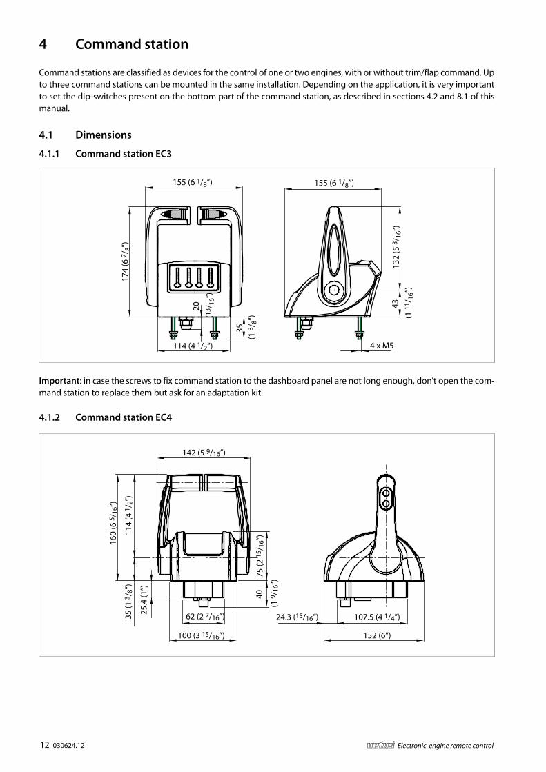
4 Command station
Command stations are classified as devices for the control of one or two engines, with or without trim/flap command. Up to three command stations can be mounted in the same installation. Depending on the application, it is very important to set the dip-switches present on the bottom part of the command station, as described in sections 4.2 and 8.1 of this manual.
4.1 Dimensions
4.1.1 Command station EC3
Important: in case the screws to fix command station to the dashboard panel are not long enough, don’t open the com-mand station to replace them but ask for an adaptation kit.
4.1.2 Command station EC4
CO
MM
AN
D
EN
GIN
E 2
WA
RM
/S
EN
GIN
E 1
132
(5 3
/ 16”
)43
(1 1
1 /16
”)
4 x M5
35 (1
3/ 8
”)
20 (1
3 /16
”)
114 (4 1/2”)
174
(6 7
/ 8”)
155 (6 1/8”) 155 (6 1/8”)
100 (3 15/16”)
62 (2 7/16”)
40
(1 9
/ 16”
)
25.4
(1”)
114
(4 1
/ 2”)
160
(6 5
/ 16”
)
35 (1
3/ 8
”)
75 (2
15 /
16”)
142 (5 9/16”)
152 (6”)
107.5 (4 1/4”)24.3 (15/16”)

030624.12 13vetus® Electronic engine remote control
4.2 Friction adjustment
4.2.1 Command station EC3To adjust the inner friction of the command lever, remove the PVC cap (A) and unscrew the fixing screw. It is possible to adjust the friction screwing and unscrewing the inner screw placed into the hole (B). When the regulation will be done, mount the screw and the plastic cap.
Important: in case of command station for one engine, the friction is placed under the right command lever.
4.2.2 Command station EC4In order to adjust the friction of the lever, it is necessary to remove the screw A placed below the plastic base of the com-mand station. With the help of an hexagon screw driver size 3 mm you can loosen or tighten the screw and the friction will become correspondingly softer or harder.Once the friction has been adjusted, close again the hole with screw A. Important: In case of a command station for single engine, the friction is present only on the left lever.
A
B
C
A
B
3

14 030624.12 vetus® Electronic engine remote control
4.3 Programming of the command station
At power up, the command station makes a sequence of two flashes. The first flash identifies the number of motors and the second identifies the number of actuators present in the system. According to the length of each flash, the command station is differently configured. You need to configure the command station in relation to the type of installation. It is also possible to modify the con-figuration of the command station by keeping pressed before powering up and continuing to keep them pressed for 6 seconds after power up, the following push buttons:
• the two internal push buttons (Warn/Sync + Command), in this case you modify the number of actuators
• (Engine left + Engine right), in this case you change the number of motors on the boat
Possible configurations are according to the following table:
1° flash (identifies the number of motors) 2° flash (identifies the number of actuators)
Installation with 1 motor and 1 actuator
Long (3 seconds) Long (3 seconds)
Installation with 2 mo-tors and 1 actuator
Short (less than 1 second) Long (3 seconds)
Installation with 2 mo-tors and 2 actuators
Short (less than 1 second) Short (less than 1 second)
Important: from the factory, the command station is configured with the first flash short and the second flash long.
1. To configure the command lever for an installation with 2 actuator boxes, press the two central push buttons (Warm/Sync e Command) before powering up the command lever and continue to keep them pressed for 6 seconds. The lever is now configured for installations with two motors and two actuators. At the next normal power up, the com-mand lever will make a sequence of 2 short flashes.
2. In case you need to configure again the command lever for installation with 2 motors and 1 actuator, repeat the pro-cedure of point 1.
4.4 Command station label
Under the base of the command station it is present the follow-ing label.
This labels indicates the code of the command station, the se-rial number and the different dip-switches configuration ac-cording to the type of the command station.
Important 1: these configurations are valid according to schemes from section 7.1 to t.5. in case of different configura-tions, contact the constructor technical department
Important 2: in the same installation can’t coexist a “1st com-mand station FSM” and a “1st command station”. “1st command station FSM” replaces “1st command station” and vice versa.
DIP switch configuration
1 2 3 4
1 st command station
1 st command station FSM
2 nd command station
3 rd command station
Code:
S/N:

030624.12 15vetus® Electronic engine remote control
4.5 Command station codes
Command stations Description Code Command station 1 motor EC3 EC3H1
Command station 1 motor EC3 with TRIM option EC3HT1
Command station 2 motors EC3 EC3H2
Command station 2 motors EC3 with TRIM option EC3HT2 Command station 1 motor EC4 EC4H1
Command station 1 motor EC4 with TRIM option EC4HT1
Command station 2 motors EC4 EC4H2
Command station 2 motors EC4 with TRIM option EC4HT2
16 030624.12 vetus® Electronic engine remote control
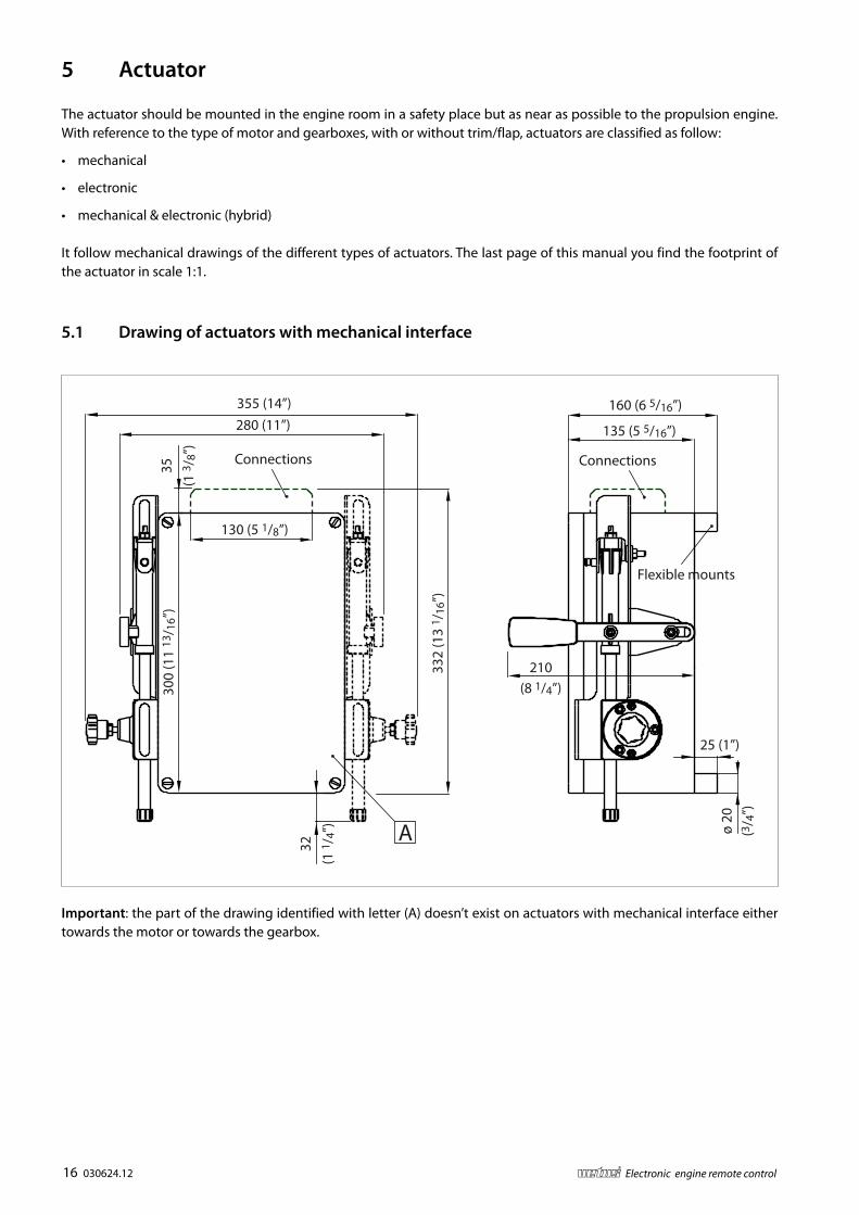
5 Actuator
The actuator should be mounted in the engine room in a safety place but as near as possible to the propulsion engine. With reference to the type of motor and gearboxes, with or without trim/flap, actuators are classified as follow:
• mechanical
• electronic
• mechanical & electronic (hybrid)
It follow mechanical drawings of the different types of actuators. The last page of this manual you find the footprint of the actuator in scale 1:1.
5.1 Drawing of actuators with mechanical interface
Important: the part of the drawing identified with letter (A) doesn’t exist on actuators with mechanical interface either towards the motor or towards the gearbox.
25 (1”)ø
20(3
/ 4”)
210(8 1/4”)
160 (6 5/16”)
135 (5 5/16”)
355 (14”)280 (11”)
130 (5 1/8”)
35(1
3/ 8
”)30
0 (1
1 13
/ 16”
)
32(1
1/ 4
”)
332
(13
1 /16
”)
A
Flexible mounts
ConnectionsConnections

030624.12 17vetus® Electronic engine remote control
5.2 Drawing of full electronic actuator
V2.0
V3.0
LEFT ENGINERIGHT ENGINE
+12
V
Fuse
CAN
Bus
160 (6 5/16”)
135 (5 5/16”)
200 (7 7/8”) 35 (1 3/8”)
300
(11
13/ 1
6”)
25 (1”)
ø 20
(3/ 4
”)
200
(7 7
/ 8”)
Connections
LEFT ENGINERIGHT ENGINE
+12
V
Fuse
CAN
Bus
160 (6 5/16”)
135 (5 5/16”)
200 (7 7/8”) 35 (1 3/8”)
300
(11
13/ 1
6”)
25 (1”)
ø 20
(3/ 4
”)
200
(7 7
/ 8”) Left engineRight engine
Clut
ch
Clut
ch
Trol
ling
Trol
ling
Thro
ttle
Thro
ttle
Can
bus
Fuse
+12
V+2
4 V
Connections

18 030624.12 vetus® Electronic engine remote control
How to mount the actuator
Mount the actuator leaving a space of at least 25 cm on each side
Do not install the actuator with the connectors upwards
A < 25cm (10”)
A > 25cm (10”)
A
A
A A
A
A
A < 25cm (10”)
A > 25cm (10”)
A
A
A A
A
A

030624.12 19vetus® Electronic engine remote control
5.4 Actuator Codes
Actuator for 1 mechanical motor and 1 gearbox mechanical (no trim) EC3UMM1
Actuator for 1 mechanical motor and 1 gearbox mechanical (with trim) EC3UMMT1
Actuator for 1 electronic motor (V) and 1 gearbox mechanical (no trim) EC312EM1
Actuator for 2 electronic motors (V) and 2 gearboxes mechanical (no trim) EC312EM2
Actuator for 1 electronic motor (V) and 1 gearbox mechanical (with trim) EC312EMT1
Actuator for 2 electronic motors (V) and 2 gearboxes mechanical (with trim) EC312EMT2
Actuator for 1 mechanical motor and 1 gearbox solenoid driven (no trim) EC3UME1
Actuator for 2 mechanical motors and 2 gearbox solenoid driven (no trim) EC3UME2
Actuator for 1 mechanical motor and 1 gearbox solenoid driven (with trim) EC3UMET1
Actuator for 2 mechanical motors and 2 gearbox solenoid driven (with trim) EC3UMET2
Actuator for 1 electronic motor (V) and 1 gearbox solenoid driven (no trim) EC312EE
Actuator for 1 electronic motor (V) and 1 gearbox solenoid driven (with trim) EC312EET
5.3 Actuator labels
Inside the actuator there are two labels indicating code and serial number. Please write them down in case you call for assistance.
Actuator code Serial number

20 030624.12 vetus® Electronic engine remote control
5.5 Electronic Actuator Boards
5.5.1 Actuator board ver. 3.1
Position on board Pin Description Output cable
JP8 Supply1 Vdc
Wall connector2 GND
JP9 Engine DX
2
MOD2 (Rev.3)
V_out CH1
4 poles3 V_out CH2
1 GND CH2
4 GND CH1
JP10 Engine SX
2
MOD2 (Rev.3)
V_out CH1
4 poles3 V_out CH2
1 GND CH2
4 GND CH1
Important: channels 1 and 3 are dedicated to the electronic engine (ECU) while the channels 2 and 4 are dedicated to the inverter for electric motors (hybrid motor applications).
JP12
UPDOWN ENTER
JP1
JP2
JP7
JP13
JP11
JP14JP15
JP19
21
JP8 JP3 JP18 JP17 JP16JP
10JP
9JP
6JP
5
Fuse

030624.12 21vetus® Electronic engine remote control
5.5.2 Relays PCB version 1.0 for electronic gearboxes
Relay port gearbox Relay starboard gearbox Solenoid gearbox Trim command
1.1 5.1 Forward (brown) Trim “-“ (nero)
1.2 5.2
1.3 5.3 Vdc (yellow/green) Vdc (brown)
2.1 6.1 Reverse (blue) Trim “+” (grey)
2.2 6.2
2.3 6.3
3.1 7.1 Trim “–“ (brown) Trailer (yellow/green)
3.2 7.2
3.3 7.3 Vdc (yellow/green)
4.1 8.1 Trim “+” (blue)
4.2 8.2
4.3 8.3
Power supplyRe
lay
1
Rela
y 2
Rela
y 3
Rela
y 4
Rela
y 5
Rela
y 6
Rela
y 7
Rela
y 8

22 030624.12 vetus® Electronic engine remote control
5.5.3 Relays PCB version 2.0 for electronic gearboxes
Pin Description
1 Vdc
2 GND
3 Vdc
4 GND
5 Left engine – Trim common contact
6 Left engine – Trim +
7 Left engine – Trim -
8 Left engine – Trailer
9 Left engine - Common neutral relays contact
10 Left engine - NC contact neutral relays
11 Left engine – Forward gear
12 GND
13 Left engine – Reverse gear
14 GND
15 Right engine - Forward gear
16 GND
17 Right engine - Reverse gear
18 GND
19 Right engine - Common neutral relays contact
20 Right engine - NC contact neutral relays
21 Right engine - Common trim contact
22 Right engine - Trim +
23 Right engine - Trim -
24 Right engine – Trailer
1 2 3 4 5 6 7 8 9 10 11 12 242322212019181716151413
Fuse

030624.12 23vetus® Electronic engine remote control
5.5.4 Relays PCB version 3.0 for electronic gearboxes with trolling option
Pin Description
1 VDC
2 GND
3 (Not connected)
4 GND (connect to Wire ID 4 and 6 of “Gearbox + neutral” connectors, both left and right)
5 Connect to VDC (Pin 1)
6 Forward Left (Wire ID 1, “Gearbox + neutral” connector)
7 Backward Left (Wire ID 2, “Gearbox + neutral” connector)
8 (Not connected)
9 Neutral relais – NC contact – Left (Wire ID 3, “Gearbox + neutral” connector)
10 Neutral relais – COM – Left (Wire ID 5, “Gearbox + neutral” connector)
11 trolling Left (BROWN, “Trolling” connector)
12 trolling Left (GND, BLUE, “Trolling” connector)
13 (Not connected)
14 (Not connected)
15 trolling Right (BROWN, “Trolling” connector)
16 trolling Right (GND, BLUE, “Trolling” connector)
17 (Not connected)
18 (Not connected)
19 Neutral relais – COM – Right (Wire ID 5, “Gearbox + neutral” connector)
20 Neutral relais – NC contact – Right (Wire ID 3, “Gearbox + neutral” connector)
21 Connect to VDC (Pin 1)
22 Forward Right (Wire ID 1, “Gearbox + neutral” connector)
23 Backward Right (Wire ID 2, “Gearbox + neutral” connector)
24 (Not connected)
FuseFusibile
1 2 3 4 5 6 7 8 9 10 422111 2322212019181716151413

24 030624.12 vetus® Electronic engine remote control
5.5.5 CANBus PCB for motor with CANBus interface
Terminal block Terminal n° Description Wire colour Type of cable
JP4 4 Can_H White 2 poles
5 Can_L Blue
Important: you need a CANBus board per each CANBus engine
The out-coming cable has a length of 3 meters. Maximum current per each channel is 100 mA. Out signals are protected against short circuit towards ground and towards power supply. CANBus termination resistor of 120 ohm is already implemented on the PCBoard but, if necessary, it can be removed.
5.5.6 Galvanic insulation PCB for analogue voltage signals
This option can be used in those cases where there are voltage differences between different ground points on the boat. A non optimum ground network can generate circuit currents and therefore disturbances in the transmission of com-mand signals (see section 10.1.5.). Each PCB performs the galvanic insulation of 2 command signal up to 250 Vdc. On each actuator it is possible to mount 2 PCBs for the interface towards:
• Electronic ECU with voltage signal
• Electronic ECU with CANBus interface
• Command of hybrid motors frequency converter driven through a voltage signal
The PCB is mounted inside of the actuator and there aren’t any special precaution to follow durig commissioning.
J3 J1 J4
1 6543212 12 3 4 5 6

030624.12 25vetus® Electronic engine remote control
6 Accessories and Options
Cables reported here below are used in standard instal-lations. For specific motors there are anyhow available cables with their proper connectors; in case you need cables for specific motors, please contact the supplier.
Important: for a correct mounting plug in the connec-tor at 90° with respect to wall side of the actuator box. Rotate then the ring until the cable enters into the counterpart M12.If the cable has been inserted correctly, it must be pos-sible to screw completely by hand the cable without too much efforts.
Connector for throttle cables
Connector for CANbus data transmission cable
90°
Cable connector
Polarization
Wall mounted connector
Cable connector
Polarization
Wall mounted connector

26 030624.12 vetus® Electronic engine remote control
6.1 CANBus data transmission cable
Length Code
L=3 m DTCAN3M
L=5 m DTCAN5M
L=10 m DTCAN10M
6.2 Cable actuator – electronic motor (V), Electronic throttle universal
Length Code
L=3 m EC3E3U
Important: this cable is without connector on motor side
L
Grey
Black
L

030624.12 27vetus® Electronic engine remote control
6.2.1 VF – Throttle CANBus command cable
6.3.1 VF – Cable for gearbox solenoid driven
Length CodeL=3 m EC3G3M
Length Code
L=3 m EC3E3M
6.3 Cable actuator – gearbox solenoid driven
For the connection towards the gearbox solenoid driven, please refer to section 10.2.3. of this manual.
Length CodeL=3 m EC3G3M
Important: this cable is without connector on gearbox side
L
L
Black 2
Black 1
Conn
ecto
r 3-p
oleYellow/Green

28 030624.12 vetus® Electronic engine remote control
6.4 Actuator – Trolling valve cable & Actuator box – Trim/flap cable
The same cable is used either to connect the Actuator to the Trolling valve and the Flap actuator box to the flap option.
• for the connection towards the trolling valve, use only back 1 and black 2 wires.
• For the connection towards the trim/flap, please refer to section 10.2.3. of this manual.
Length Code
L=3 m EC3T2
Important: this cable is without connector on trolling valve side and on the flap/pump side
6.5 Cable actuator – Mercruiser® trim pump
The cable for the trim pump of Mercruiser sterndrive has a length of 3 meters; in the cabling are included the fast-on con-nections to the microswitch for the end of stroke.
Length Code
L=3 m EC3T3MM
L
Black 2
Black 1
Conn
ecto
r 3-p
oleYellow/Green
Yellow
Blue
Red
Mercruiser® pump sideActuator side

030624.12 29vetus® Electronic engine remote control
6.6 T-Splitter
6.7 Power supply connector
Code: CANT
Code: EC3SUP
Important: cabling instruction of power supply connector are at section 10.1.1. of this manual.
6.8 Cable actuator – gearbox + neutral relais
For the connection towards the gearbox solenoid driven, please refer to section 10.2.3. of this manual.
Length Code
L=3 m ECG3/6
Important: this cable is without connector on gearbox side
33.5 28.4
40.5
30 43 37
ø 21
ø 27
L
Black 2Black 1
Yellow/Green
Black 4Black 3
Black 6Black 5
30 030624.12 vetus® Electronic engine remote control
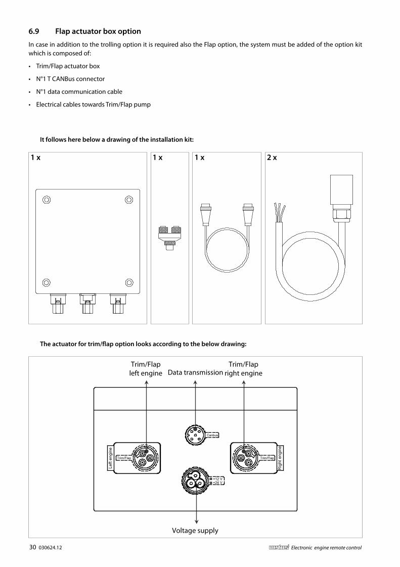
6.9 Flap actuator box option
In case in addition to the trolling option it is required also the Flap option, the system must be added of the option kit which is composed of:
• Trim/Flap actuator box
• N°1 T CANBus connector
• N°1 data communication cable
• Electrical cables towards Trim/Flap pump
1 x 1 x 1 x 2 x
The actuator for trim/flap option looks according to the below drawing:
It follows here below a drawing of the installation kit:
Canbus
+24 V+12 V
Trim/FlapTrim/Flap
Left
engi
ne
Rig
ht e
ngin
e
Data transmission
Voltage supply
Trim/Flapleft engine
Trim/Flapright engine
030624.12 31vetus® Electronic engine remote control
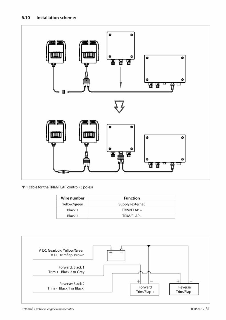
6.10 Installation scheme:
N° 1 cable for the TRIM/FLAP control (3 poles)
Wire number FunctionYellow/green Supply (external)
Black 1 TRIM/FLAP +
Black 2 TRIM/FLAP -
EN
GIN
E 1
WA
RM
/S
EN
GIN
E 2
CO
MM
AN
D
CO
MM
AN
D
EN
GIN
E 2
WA
RM
/S
EN
GIN
E 1
EN
GIN
E 1
WA
RM
/S
EN
GIN
E 2
CO
MM
AN
D
CO
MM
AN
D
EN
GIN
E 2
WA
RM
/S
EN
GIN
E 1
V DC Gearbox: Yellow/GreenV DC Trimap: Brown
Forward: Black 1Trim + : Black 2 or Grey
Reverse: Black 2Trim - : Black 1 or Black) Reverse
Trim/Flap -Forward
Trim/Flap +

32 030624.12 vetus® Electronic engine remote control
6.11 Trim/Flap option
Flap/trim command can be activated directly from the command station with the buttons ‘+’ and ‘-’. The commands are sent to the actuator from the command station. The relay card fitted on the actuator box activates the flap/trim com-mands on the hydraulic pump.For installations with two engines, in case of “Synchro” mode operation, the buttons on the right-hand side operate the trims of both engines simultaneously.
Command station EC3
Version for one engine Version for two engines
Command station EC4
Version for one engine
Trim or flap can be activated directly from the command sta-tion with “+” and “-“ pushbut-tons. These pushbuttons are placed on the lateral side of the left lever.
Version for two engines
Trim or flap are tuned with “+” and “-“ pushbuttons placed on the keypad (a couple for each motor).It is also possible to command in sychro trim or flap of both motors with the “+” and “-“ pushbuttons placed on the lateral side of the left lever.This feature is very comfortable during navigation
+
Engine
CommandWarm/Sync
Engine
Trim

030624.12 33vetus® Electronic engine remote control
7 System types and installation schemes
The actual plant architecture is related to
• type and quantity of engines;
• type of gearboxes;
• number of command stations.
Actuators and command stations, which communicate together through the CANBus network, must be configured in relation to where they are connected to the CANBus network. In the following installation schemes you can find:
• components necessary to build an installation;
• configuration of actuators and command stations in relation of their position on the CANBus network.
The following installation types and schemes cover the most common application cases.
7.1 Installation with 2 mechanical actuators – solution A
This installation scheme is valid for systems with:
• Up to 3 command stations and 2 engines with mechanical throttle, mechanical gearbox, with/without trim;
• Up to 3 command stations and 2 hybrid engines with mechanical throttle, mechanical gearbox, analogue outputs for electric engine inverter driven, with/without trim.
Code: DTCANxx
JP19: YES (end-line) JP19: NO (end-line)
JP14: YES (address)JP14: NO (address)
432143214321Actuator forport engine
Actuator forstarboard
engine
Command station ACommand station BCommand station C
Data transmission cable

34 030624.12 vetus® Electronic engine remote control
7.2 Installation with 2 mechanical actuators – solution B
This installation scheme is valid for systems with:
• Up to 3 command stations and 2 engines with mechanical throttle, mechanical gearbox, with/without trim;
4321 4321 4321
JP19: NO (end-line)
JP14: NO (address)
JP19: NO (end-line)
JP14: YES (address)
Code: DTCANxx
Actuator forport engine
Actuator forstarboard
engine
Data transmission cable
2nd command station3rd command station1st command station

030624.12 35vetus® Electronic engine remote control
7.3 Installation with 2 mechanical actuators – solution C
Actuators are placed at the ends of the CANBus network
This installation scheme, typical for catamaran applications, is valid for systems with:
• Up to 3 command stations and 2 engines with mechanical throttle, mechanical gearbox, with/without trim;
4321 4321 4321
JP14: NO (address)
JP19: YES (end-line)
JP14: YES (address)
JP19: YES (end-line)
Code: DTCANxx
Actuator forport engine
Actuator forstarboard
engine
Data transmission cable
Command station A Command station B Command station C

36 030624.12 vetus® Electronic engine remote control
7.4 Installation with 1 actuator – solution D
The actuator is placed at one end of the CANBus network.
This installation scheme is valid for systems with:
• up to 3 command stations and 1 engine with mechanical throttle, mechanical gearbox, with/without trim (or flap);
• up to 3 command stations with 1 or 2 mechanical throttles and 1 or 2 solenoid gearboxes, analogue outputs for elec-tric engine inverter driven, with/without (or flap);
• up to 3 command stations and 1or 2 engines with electronic throttle (voltage), mechanical gearbox, with/without trim (or flap);
• up to 3 command stations and 1 or 2 engines with electronic throttle (voltage), solenoid driven gearbox, with/without trim (or flap);
4321 4321 4321
JP19: YES (end-line)
JP14: NO (address)
Code: DTCANxx
Actuator
Data transmission cable
2nd command station 3rd command station1st command station

030624.12 37vetus® Electronic engine remote control
7.5 Installation with 1 actuator – solution E
The actuator is placed in the middle of the CANBus line.
This installation scheme is valid for systems with:
• up to 3 command stations and 1 engine with mechanical throttle, mechanical gearbox, with/without trim (or flap);
• up to 3 command stations with 1 or 2 mechanical throttles and 1 or 2 solenoid gearboxes, analogue outputs for elec-tric engine inverter driven, with/without (or flap);
• up to 3 command stations and 1or 2 engines with electronic throttle (voltage), mechanical gearbox, with/without trim (or flap);
• up to 3 command stations and 1 or 2 engines with electronic throttle (voltage), solenoid driven gearbox, with/without trim (or flap);
432143214321
JP14: NO (end-line)
JP14: NO (address)
Code: DTCANxx
Actuator
Data transmission cable
2nd command station3rd command station1st command station

38 030624.12 vetus® Electronic engine remote control
This installation scheme is valid for systems with up to 3 command stations and 2 engines and gearboxes, full electronic
7.6 Installation with 2 actuators – solution F
Code: DTCANxx
JP19: YES (end-line)
JP14: NO (address)
432143214321
Command station ACommand station BCommand station C
Actuator full electronic
Left and right engines Actuator for
flap option
Data transmission cable

030624.12 39vetus® Electronic engine remote control
7.7 Installation with 2 actuators – solution G
This installation scheme is valid for systems with up to 3 command stations and 2 engines and gearboxes, full electronic
Code: DTCANxx
4321 4321 4321
JP19: NO (end-line)
JP14: NO (address)
Command station A Command station BCommand station C
Actuator full electronic
Left and right engines Actuator for
flap option
Data transmission cable

40 030624.12 vetus® Electronic engine remote control
8 Configuration of the CANBus network: end of line termination re-sistor and address setting of command stations and actuators
According to the number and to the position on the CANBus communication net, command stations and actuators must be properly configured to guarantee the correct functioning of the system. End of line termination resistor must be ena-bled, in case the device is placed at the end of the CANBus network.
8.1 Configuration of the command station
This operation allows to setup the command station in relation to its position on the CANBus net. Each command station must have a different address number and if the command station is connected at the end of the CANBus net, the end line dip-switch must be enable (ON).
Under the base of the command station there is a plastic cap. Unscrewing it, you can access to the dip-switches. Operation:
• unscrew the plastic cap;
• set the dip-switch position according to the following table;
• screw again the cap.
Dip-switch 1: OFF end-line resistance disabled ON end-line resistance enabled
Dip-switch 2: OFF Trolling disabled ON Trolling enabled
Dip-switch 3 and 4: identify the command station
Dip- switch 3 Dip- switch 4
Command station position A OFF OFF
Command station Fast Start-up Mode (this is alternative to command station position A)
ON OFF
Command station position B OFF ON
Command station position C ON ON
Important 1: if there are more command stations connected to the same CANBus network, each command station must have a unique address/position. This unique position of the command station is defined by the con-figuration of the dip-switches.
Important 2: “command station A” and “command station Fast Start-up Mode” cannot co-exist in the same system: ei-ther you have a “Fast Start-up Mode” or “Command station in position A”.
Important 3: To configure the dip-switches of each command station, please refer to the installation schemes reported from section 7.1. to section 7.5.
Important 4: dual command station (command station for two motors) is configured from the factory to be mounted in systems with only one actuator. This is the typical application where there are motors and/or gearboxes with electronic interface (like it is described in sections 7.4 and 7.5). In case of systems with two propulsion systems equipped with mechanical motors and mechanical gearboxes, you need to use two mechanical
DIP switch configuration
1 2 3 4
1 st command station
1 st command station FSM
2 nd command station
3 rd command station

030624.12 41vetus® Electronic engine remote control
actuators (installations described at sections 7.1, 7.2 and 7.3). If this is the case, the command station must be re-configured as described at section 4.2.
Important 5: If trolling function is disabled by setting switch 2=OFF, trolling is not activable (on a command station that has the command, pressing the Command button will not produce any effect: its behaviour will be the one of a standard plant).
8.2 Configuration of the actuator
To configure the actuator it is necessary to:
• enable or disable the end of line resistance
• define the CANBus address
These operations must be according to the position of the actuator as described in the schemes of chapter 7.
Actuator PCBoard version 2.0
JP14: YES (adress) Enable the address short-circuiting terminals 5 and 6 of JP3
JP19: YES (end-line)Enable the 120 Ω short-circuiting either terminals 8 and 9 of JP5 or terminals 2 and 3 of JP3
JP3
JP13
JP2
17JP5JP9JP10
JP8JP11
JP4
JP7
End-line resistance (120 Ω) Address
Fuse

42 030624.12 vetus® Electronic engine remote control
JP14 defines the CAN Bus address of the actuator. Factory setting is JP14 = OFF JP19 enables (ON) or disables (OFF) the line termination. Factory setting is JP19 = ON
In some documentation, alternative to ON or OFF there are the respectively YES and NO, e.g.:
JP14: YES (adress) the switch JP14 is ON
JP19: YES (end-line) the switch JP19 is ON
JP12
UP DOWNENTER
JP1
JP2
JP7
JP13
JP11
JP14JP15
JP19
JP8JP3JP18JP17JP16
JP10
JP9
JP6
JP5
Jumper to enable end-line resistance
Jumper to enable address
Fuse
Actuator PCBoard version 3.1
The actuator configuration changes according if the system is with one or two actuators:
Installations with 1 actuator Installations with 2 actuators
JP14 = OFF left actuator is with JP14 = OFF
right actuator is with JP14 = ON
The setting of JP19 is depending if the actuator is in the middle (JP19 = OFF) or at the end of the CANBus network (JP19 = ON)

030624.12 43vetus® Electronic engine remote control
9 Push-pull cables installation
For the connection of the push-pull cable to the actuator, it is necessary to use its proper connection kit. The available kits are for Volvo® cable (E2, E3, C0, C3, C33…), Johnson® cable and Mercruiser® stern drive cable.
9.1 Connection kit
Standard connection kit Connection kit for Johnson® cable Connection kit for Mercruiser® cable
2x
2x 2x2x
2x
Each kit is sufficient to connect two push-pull cables.
9.2 Standard push-pull cables
How to mount:
1. tighten the eyelet on the thread of the cable;
2. screw the emergency knob placed on the actuator until the emergency lever is free to move;
3. insert the push-pull cable between the stainless steel fork plate and the aluminium locking device as shown in the picture;
4. insert the push-pull cable into the bracket on the actuator and connect the eyelet to the pin and lock it using the Seeger. Use the emergency lever to help during this operation;
5. lock the aluminium device with the screw, the brass spacer and the washer, at the distance indicated into the picture;
6. loose the emergency knob and move the emergency lever until the device will reach the correct position (it will be automatically locked)
Important: before the assembly, the throttle must be in minimum position and the gearbox must be in neutral position.
ca. 5
0 (2
”)

44 030624.12 vetus® Electronic engine remote control
9.3 Push-pull cable outgoing from the Mercruiser® stern driver
In case it is used the push-pull cable outgoing directly from the Mercruiser® stern driver, the plastic Mercruiser® bracket is not necessary.
ca. 5
0 (2
”)
Important: before the assembly, the throttle must be in minimum position and the gearbox must be in neutral position.
How to mount:
1. tighten the eyelet on the thread of the cable;
2. screw the emergency knob placed on the actuator until the emergency lever is free to move;
3. insert the push-pull cable between the plastic cup and the aluminium locking device as shown in the picture;
4. insert the push-pull cable into the bracket on the actuator;
5. put the brass spacer on the pin and fix the plastic eyelet of the cable on it. Lock the eyelet with the Seeger. Use the emergency lever to help during this operation;
6. lock the aluminium device with the screw, the brass spacer and the washer at the distance indicated into the picture;
7. loose the emergency knob and move the emergency lever until the device reaches the correct position (it will be automatically locked)

030624.12 45vetus® Electronic engine remote control
9.4 Johnson® push-pull cable
ca. 1
4 (9
/ 16”
)
Important: before the assembly, the throttle must be in minimum position and the gearbox must be in neutral position.
How to mount:
1. tighten the eyelet on the thread of the cable;
2. screw the emergency knob placed on the actuator until the emergency lever is free to move;
3. put to the aluminium device on the cable and insert them into the bracket on the actuator;
4. put the brass spacer on the pin and fix the eyelet on the cable on it. Lock the eyelet with the Seeger. Use the emer-gency lever to help during the operations;
5. lock the aluminium device with the screw, the brass spacer and the washer at the distance indicated into the picture;
6. loose the emergency knob and move the emergency lever until the device reaches the correct position (it will be automatically locked)
46 030624.12 vetus® Electronic engine remote control
Vdc (the plug ismarked with in red)
GND - it ismarked with ‘N’
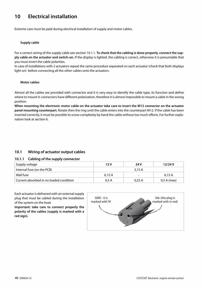
10.1 Wiring of actuator output cables
10.1.1 Cabling of the supply connectorSupply voltage 12 V 24 V 12/24 V
Internal fuse (on the PCB) 3,15 A
Wall fuse 6,15 A - 6,15 A
Current absorbed in no loaded condition 0,5 A 0,25 A 0,5 A (max)
Each actuator is delivered with an external supply plug that must be cabled during the installation of the system on the boat. Important: take care to connect properly the polarity of the cables (supply is marked with a red sign).
10 Electrical installation
Extreme care must be paid during electrical installation of supply and motor cables.
Supply cable
For a correct wiring of the supply cable see section 10.1.1. To check that the cabling is done properly, connect the sup-ply cable on the actuator and switch-on. If the display is lighted, the cabling is correct, otherwise it is presumable that you must invert the cable polarities.In case of installations with 2 actuators repeat the same procedure separated on each actuator (check that both displays light on) before connecting all the other cables onto the actuators.
Motor cables
Almost all the cables are provided with connector and it is very easy to identify the cable type, its function and define where to mount it: connectors have different polarization, therefore it is almost impossible to mount a cable in the wrong position. When mounting the electronic motor cable on the actuator take care to insert the M12 connector on the actuator panel mounting counterpart. Rotate then the ring until the cable enters into the counterpart M12. If the cable has been inserted correctly, it must be possible to screw completely by hand the cable without too much efforts. For further expla-nation look at section 6.

030624.12 47vetus® Electronic engine remote control
Starter motors: the cables that connect the battery to the starter motors must have a cross-section of at least 50 mm2
(AWG 0) (both the ‘plus’ and the ‘minus’ cable).
Electrical installation: the ‘minus’ cable of the actuator must be connected directly to the battery.
Actuator: each actuators must be connected with both batteries. The ‘plus’ cables must be fitted with a 10 A de-coupling diode. In this way the actuator will be supply from the most charged battery. The minimum section of the cable must be of 2,5 mm2 (AWG 12)
Actuators: each actuator must be supplied from its bat-tery.
‘R’ is a relay that is activated by the keys of the port and the starboard engine
‘R1’ is a relay that is activated by the key of the port engine while ‘R2’ is a relay that is activated by the key of the star-board engine
BatteryBattery
Portside engine Starboard engine
Actuator
BatteryBattery
Portside engine Starboard engine
Actuator Actuator

48 030624.12 vetus® Electronic engine remote control
10.1.2 Electrical installation of systems with 1 motor, 1 actuator and 1 dashboard
It follows the electrical schemes to be used to make the connection to power supply, including dimensional value of the electrical components.
V D
C
GN
D
GN
D -
Engi
ne
Key
switc
h
V D
C Ba
tter
y
Actuator
Ref. Description 12 V power supply 24 V power supply
D Diode 10 A, 20 V 5 A, 24 V
R Relè 10 A, 12 V 5 A, 24 V
F Fuse 10 A
Supply cable cross section 2.5 mm2 1.5 mm2

030624.12 49vetus® Electronic engine remote control
10.1.3 Electrical installation of systems with 2 motors, 1 or 2 actuators and 2 dashboards
RR
F F
D
DD
D
V D
C
GN
D
Actuator
GN
D -
Port
Eng
ine
Key
switc
h - P
ort E
ngin
e
V D
C Ba
tter
y - P
ort E
ngin
e
V D
C Ba
tter
y - S
tarb
oard
Eng
ine
GN
D -
Sta
rboa
rd E
ngin
e
Key
switc
h - S
tarb
oard
Eng
ine
The same scheme can be used in case there are 2 actuators instead of only one.For the detailed list of components, please refer to the table at section 10.1.2.
50 030624.12 vetus® Electronic engine remote control
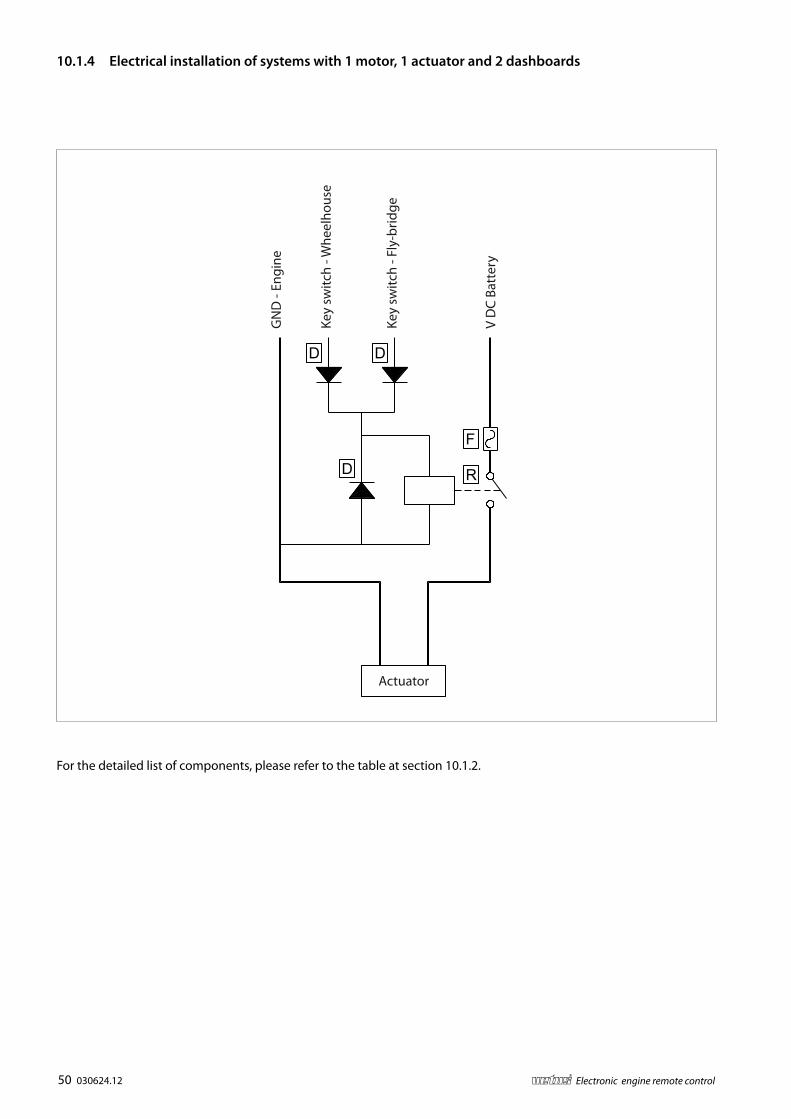
10.1.4 Electrical installation of systems with 1 motor, 1 actuator and 2 dashboards
F
RD
D D
Actuator
GN
D -
Engi
ne
Key
switc
h - W
heel
hous
e
V D
C Ba
tter
y
Key
switc
h - F
ly-b
ridge
For the detailed list of components, please refer to the table at section 10.1.2.

030624.12 51vetus® Electronic engine remote control
10.1.5 Dimensional criteria of the power cables for the overall installation
For supply cabling respect the following conditions:
• Cables from the battery to motor starter (both positive and negative poles) must have a minimum cross section of 50 mm2, if not specified a higher cross section by the motor supplier.
• The GND of the actuator must be connected directly to the negative pole of the battery. Minimum cross section is 2,5 mm2
• In case of systems with electronic throttle, it is very important to connect to a common GND point (GND buss bar) all the negative poles (GND) of every electronic equipment.
P
ECU
Actuator
Motor starter
Bow thruster
Buss bar for GND

52 030624.12 vetus® Electronic engine remote control
10.2 Electrical cabling of the outgoing cables from the actuator
10.2.1 Cabling of actuators for mechanical propulsion systems
+12 V
Throttle
Fuse
(+12
V)
TrimClutch
TrimClutch
THROTTLECLUTCH
LEFT ENGINE RIGHT ENGINE
THROTTLECLUTCH
ThrottleCanbus
+24 V
Motor ECU/inverter
CANbus datatransmission cable
Motor ECU/inverter
Port
eng
ine
Star
boar
d en
gine
Func
tion
of th
epu
sh-p
ull c
able
Solenoid drivengearbox/Trim (ap)
Voltage supply
Func
tion
of th
epu
sh-p
ull c
able
Solenoid drivengearbox/Trim (ap)
Important: this cabling is valid for the following systems, with or without trim:
• mechanical motor and mechanical gearbox (only 1 propulsion group per actuator)
• mechanical engine and solenoid driven gearbox (up to 2 propulsion groups per actuator)
• electronic engine and mechanical gearbox (up to 2 propulsion groups per actuator)

030624.12 53vetus® Electronic engine remote control
10.2.2 Cabling of actuators V2.0 for electronic propulsion systems
These actuators are used where either the motor and the gearbox are electronic.
Clutch Throttle
ThrottleClutchCANBus
Fuse
+12 V
RIG
HT
EN
GIN
ELE
FT E
NG
INE
Gearbox + Neutral Throttle Data transmision
Gearbox + Neutral Throttle Fuse Voltage supply
Port
Eng
ine
Star
boar
d En
gine
Important: in case of single engine installation, use only the connectors for the right engine.
V2.0

54 030624.12 vetus® Electronic engine remote control
Per each engine it is necessary:
N° 1 cable for the throttle.
Per each gearbox and trolling group are necessary:
N° 1 cable 6 poles
Wire number Function1 Forward signal (solenoid valve)
2 Reverse signal (solenoid valve)
3 Neutral relais
4 Forward GND signal (solenoid valve)
5 Neutral relais
6 Reverse GND signal (solenoid valve)
N° 1 cable for the PWM command of the trolling (2 wire used)
Wire identifier FunctionBROWN Trolling command PWM signal
BLUE Trolling command GND
10.2.3 Cabling of actuators V3.0 for electronic propulsion systems
These actuators are used where either the motor and the gearbox are electronic.
V3.0
Left
engi
neR
ight
eng
ine
Clutch
Clutch
Trolling
Trolling
Throttle
Throttle
Canbus
Fuse
+12 V+24 VSt
arbo
ard
engi
nePo
rt e
ngin
e
Throttle
FuseThrottle Voltage supply
Data transmissionGearbox + neutral
Gearbox + neutral
Trolling
Trolling

030624.12 55vetus® Electronic engine remote control
V DC Gearbox: Yellow/GreenV DC Trimap: Brown
Forward: Black 1Trim + : Black 2 or Grey
Reverse: Black 2Trim - : Black 1 or Black) Reverse
Trim/Flap -Forward
Trim/Flap +
10.2.4 Cabling scheme from actuator to gearbox, from actuator to trim or from actuator to flap

56 030624.12 vetus® Electronic engine remote control
11 Programming of the actuator, general guidelines
11.1 Programming keypad
The keyboard has a display with two figures and three programming pushbuttons/keys.
Colour of key Reference
Red 1 (-)
Yellow 2 (+)
Grey 3 (↵)
Important 1: command stations must be set to neutral in order to be able to access the programming of the actuators including the setting of parameters.
Important 2: command stations are already programmed in the factory and it should not be necessary to make any changes. In case it is required to modify their configuration, refer to chapter 6.1.
11.2 Display and Parameters
After power up, the display shows a sequence of 2 codes: ‘FI’ and ‘XX’:
• ‘FI’ means Firmware;
• ‘XX’ is the firmware version.
After some time the display shows “_ _”. To enter the Parameters, press at the same time keys “1” and “2”. It is now possible to move from one parameter to the other using the keys “1” and “2”. For the setting of the specific parameters follow this procedure:
1. with the actuator turned on (the display shows _ _) press both keys “1” and “2” and the first parameter will appear on the display;
2. pressing either “1” or “2” it is now possible to scroll in one or the other direction, all the parameter lists
3. pressing the key “3” the value of the parameter will be shown on the display. The display is now blinking and it is pos-sible to modify the parameter value, using the keys “1” and “2”;
4. when the parameter has been modified, use the key “3” (↵) to store the value of the parameter; the display stops blinking.
5. to set the other parameters, scroll the menu using the keys “1” and “2” and when the parameter that you would like to change is reached, follow this procedure starting from the point 3.
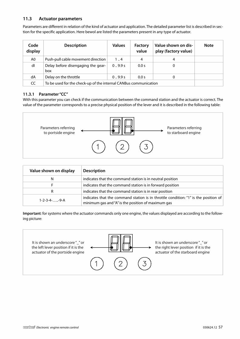
030624.12 57vetus® Electronic engine remote control
11.3 Actuator parameters
Parameters are different in relation of the kind of actuator and application. The detailed parameter list is described in sec-tion for the specific application. Here bewol are listed the parameters present in any type of actuator.
Code display
Description Values Factory value
Value shown on dis-play (factory value)
Note
A0 Push-pull cable movement direction 1 .. 4 4 4
dI Delay before disengaging the gear-box
0 .. 9.9 s 0.0 s 0
dA Delay on the throttle 0 .. 9.9 s 0.0 s 0
CC To be used for the check-up of the internal CANBus communication
11.3.1 Parameter “CC”With this parameter you can check if the communication between the command station and the actuator is correct. The value of the parameter corresponds to a precise physical position of the lever and it is described in the following table:
Value shown on display Description
N indicates that the command station is in neutral position
F indicates that the command station is in forward position
R indicates that the command station is in rear position
1-2-3-4-…..-9-Aindicates that the command station is in throttle condition: “1” is the position of minimum gas and “A” is the position of maximum gas
Important: for systems where the actuator commands only one engine, the values displayed are according to the follow-ing picture:
Parameters referring to starboard engine
Parameters referringto portside engine
It is shown an underscore “_” or the right lever position if it is the actuator of the starboard engine
It is shown an underscore “_” orthe left lever position if it is the actuator of the portside engine
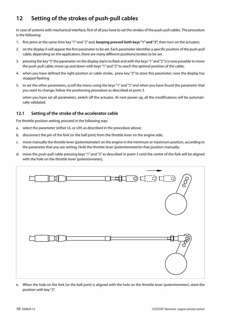
58 030624.12 vetus® Electronic engine remote control
12 Setting of the strokes of push-pull cables
In case of systems with mechanical interface, first of all you have to set the strokes of the push-pull cables. The procedure is the following:
1. first press at the same time key “1” and “2” and, keeping pressed both keys “1” and “2”, then turn on the actuator;
2. on the display it will appear the first parameter to be set. Each parameter identifies a specific position of the push-pull cable; depending on the application, there are many different positions/strokes to be set.
3. pressing the key “3” the parameter on the display starts to flash and with the keys “1” and “2” it is now possible to move the push-pull cable; move up and down with keys “1” and “2” to reach the optimal position of the cable;
4. when you have defined the right position or cable stroke, press key “3” to store this parameter; now the display has stopped flashing
5. to set the other parameters, scroll the menu using the keys “1” and “2” and when you have found the parameter that you want to change, follow the positioning procedure as described at point 3.
when you have set all parameters, switch off the actuator. At next power up, all the modifications will be automati-cally validated.
12.1 Setting of the stroke of the accelerator cable
For throttle position setting, proceed in the following way:
a. select the parameter (either UL or UH) as described in the procedure above;
b. disconnect the pin of the fork (or the ball joint) from the throttle lever on the engine side;
c. move manually the throttle lever (potentiometer) on the engine in the minimum or maximum position, according to the parameter that you are setting. Hold the throttle lever (potentiometer)in that position manually;
d. move the push-pull cable pressing keys “1” and “2” as described in point 3 until the centre of the fork will be aligned with the hole on the throttle lever (potentiometer);
e. When the hole on the fork (or the ball joint) is aligned with the hole on the throttle lever (potentiometer), store the position with key “3”.

030624.12 59vetus® Electronic engine remote control
12.2 Setting of the stroke of the gearbox cable
For gearbox positions proceed in the following way:
a. select the parameter (e.g.: 0L, 0F, 0H, 1L,1F,1H) as described in the procedure above;
b. disconnect the pin of the fork (or the ball joint) from the lever on the gearbox side;
c. move manually the lever on the gearbox in one of the three positions (reverse, neutral, forward) according to the parameter that you have set;
d. move the push-pull cable pressing keys “1” and “2” has described in point 3 until the centre of the fork is aligned with the hole on the gearbox lever;
e. when the hole on the fork (or the ball joint) is aligned with the hole on the gearbox lever, store the position with key “3”.
Important 1: when the display is flashing your are in “jog mode” and you can move back and forward the cable simply pressing “1” or “2”. When the display has a fixed light, you can scroll parameters UL,UH, 0lL, 0F, 0H…
Important 2: test the correct functioning of the gearbox and the throttle by moving the command lever. If the control lever is in forward position and the gearbox is actuated reverse, modify the parameter A0 as described at section 13.2 of this manual.
Important 3: actuators are delivered from factory with Forward, Reverse and Neutral positions coincident in the Neutral position. There is therefore no stroke between Neutral and Reverse or Neutral and Forward and the installer has to make the correct setting the stroke in order to start-up correctly the system.
Important 4: a not precise setting of the strokes may generate malfunctioning of the gearbox (delays in clutch-in, clutch-out) or an excessive current absorption on the Actuator.
Important 5: this procedure must be carried out while the motor is running and the vessel is sailing. It is important to pay the greatest attention to the settings for forward and reverse, in order to prevent sudden or uncontrolled movements of the vessel. If necessary, ask for help to a second person who can help you to switch the engine on and off, if required.
Important 6: in case of stern drive and outboard engines, if the motor isn’t running, it isn’t possible to set the strokes, because the clutch-in operation becomes very hard. In this is the case, actuate the rotation of the propeller manually, this will make easier the clutch-in of the gearbox.

60 030624.12 vetus® Electronic engine remote control
13 Programming of the actuator in installations with mechanical mo-tor and gearbox
13.1 Mounting of the push-pull cable
Please refer to section 9.
13.2 Programming of the push-pull cable strokes
For the general programming instructions please refer to section 12. With this kind of actuator you must program 5 posi-tions (2 for the throttle and 3 for the gearbox).
Parameters to set Value on display
ThrottleUL
UH
Gearbox
0L
0F
0H
Gearbox and throttle positions have to be set according to the parameters of the above table. Parameter A0 associates the direction movements of throttle and gearbox to the command of the lever. Scheme and table here below define the directions of throttle and gearbox in relation to the 4 possible values of parameter A0, with the assumption to move the command station lever in forward direction (gearbox forward and motor accelerated).
Value A0 Throttle Gearbox1 Push (direction
UL)Pull (direction
OH)
2 Push (direction UL)
Push (direction OL)
3 Pull (direction UH)
Push (direction OL)
4 Pull (direction UH)
Pull (direction OH)
The factory settings provide A0 = 4
OL
OF
OH
Gearbox
UL
UH
Throttle
Push
Pull
Push
Pull

030624.12 61vetus® Electronic engine remote control
After having set the stroke positions, it might happen that there is not the right correspondence between the direction of the lever and the movement executed by the actuator (e.g.: you move the lever forward and the gearbox cable push-ing instead of pulling). Changing the value of parameter A0 you can modify the correlation between the direction on the lever and the direction on the actuator. The following examples show how to operate in case there is not the exact correspondence between the command lever and the actuator.
System with mechanical throttle and mechanical gearbox
OL
OF
OH
Gearbox
UL
UH
Throttle
Push
Pull
Push
Pull
Problem Solution
The gearbox push-pull cable positions are inverted while the throttle push-pull cable works correctly (forward and backward positions are inverted)
Set A0=3
The gearbox is working correctly while the throttle push-pull cable positions are inverted (min and max throttle posi-tions are inverted)
Set A0=1
Both gear or throttle push-pull cables positions are inverted
Set A0=2
13.3 Specific parameters
Display code
Description ValuesFactory
valueValue shown on dis-play (factory value)
Note
A0Push-pull cable movement direc-tion
1 .. 4 4 4
dIDelay before disengaging the gearbox
0 .. 9.9 s 0.0 s 0
dA Delay on the throttle 0 .. 9.9 s 0.0 s 0
PP Proportional coefficient 0 .. 99 40 40 These para-meters must not
be changedPI Integral coefficient 0 .. 99 0 00
CC To be used for the check-up of the internal CANBus communication

62 030624.12 vetus® Electronic engine remote control
14 Programming of actuators for installations with electronic motor and mechanical gearbox
14.1 Programming of the gearbox strokes
For the general programming instructions please refer to section 12. With this kind of actuator you must program either 3 or 6 positions, depending if there are 1 or 2 propulsion systems.
14.2 Specific parameters
Display code
Description ValuesFactory
valueValue shown on dis-play (factory value)
Note
A0Push-pull cable movement direc-tion
1 .. 4 4 4
dIDelay before disengaging the gearbox
0 .. 9.9 s 0.0 s 0
dA Delay on the throttle 0 .. 9.9 s 0.0 s 0
PP Proportional coefficient 0 .. 99 40 40 These param-eters must not
be changedPI Integral coefficient 0 .. 99 0 00
CP CANBus protocol 1-99 0 00 See 17.2.2.
L1
These parameters are present only in systems with electronic engine (ECU) and/or electric with electrical engine inverter driven. Parameters to define the voltage output interface will be detailed in the following pages.
H1
C1
L2
H2
C2
L3
H3
C3
L4
H4
C4
CC To be used for the check-up of the internal CANBus communication

030624.12 63vetus® Electronic engine remote control
14.2.1 Parameter A0
After you have programmed the gearbox strokes, you need to verify the correspondence between the lever’s direction and the direction of the actuator. With parameter A0 you can modify the direction of the stroke of the actuator. With the assumption that you have done all the stroke setting with A0 = 4 (factory setting), modify the correlation between lever and actuator as described in the schemes of the next page.
System with one electronic motor and one gearbox mechanically driven
OL
OF
OH
Gearbox
Push
Pull
Problem Solution
The gearbox push-pull cable positions are inverted
Set A0=3
System with two electronic motors and two gearboxes mechanically driven
OL
OF
OH
Gearboxstarboard
engine
IL
IH
Gearboxport engine
Push
Pull
Push
Pull
IF
Problem Solution
Positions of the right gearbox are inverted while the positions of the left gearbox are correct
Set A0=3
Positions of the left gearbox are in-verted while the positions of the right gearbox are correct
Set A0=2
Positions of both gearboxes are in-verted
Set A0=1

64 030624.12 vetus® Electronic engine remote control
14.2.2 Parameters to configure the voltage output signal for electronic motors
For installations with electronic motor or hybrid motor (motor driven by a frequency converter), it is necessary to set the minimum and maximum voltage output. Voltage signal profile is defined through parameters L*, H* and C*, where “*” means 1,2,3,4.
Important: the graphic on the right represents the volt-age profile defined by parameters L,C, H. Changes of factory values could cause a system malfunctioning. Be-fore making any changes, contact our technicians.
C*
H*
L*
V
Stroke lever

030624.12 65vetus® Electronic engine remote control
15 Programming of actuators for mechanical motors and electronic gearbox
15.1 Installation of motor the push-pull cable and programming of throttle mechanical strokes
For the connection of the push-pull cables please refer to chapter 9. To set strokes refer to 12. and 13.2. Sec-tion 13.2 describes how to program actuator’s strokes in case of only one mechanical accelerator. In case of actuators for 2 mechanical accelerators and 2 elec-tronic gearboxes, the following parameters must be programmed.
Parameters Values on display
Left throttle UL
UH
Right throttle PL
PH
PL
PH
Gearboxstarboard
engine
UL
UH
Throttleport engine
Push
Pull
Push
Pull
15.2 Programming of the push-pull cable strokes
With this kind of actuator you must program 2 positions for each motor (minimum throttle and maximum throttle). For the general programming instructions please refer to section 12 and section 13.2.
15.3 Electrical cabling of the gearbox
For each gearbox are available 2 output relays. For proper wiring please refer to sections 5.5.2, 5.5.3 and 10.2.3. of this manual.
15.4 Specific parameters
Installations with electronic gearbox might require a delay time when you pass the lever directly from reverse to forward or from forwards to reverse. Factory setting is 0,5 seconds.
Code display
Description ValuesFactory
valueValue shown on dis-play (factory value)
dI Delay in switching off the gearbox 0 .. 9.9 s 0.0 s 00
dA Delay in start of throttle 0 .. 9.9 s 0.0 s 00
dF
Delay in neutral; it occurs any time you move directly from forward to reverse or from reverse to forward. This delay does not occur when from neutral you move to forward or reverse.
0 .. 9.9 s 0.5 s 05
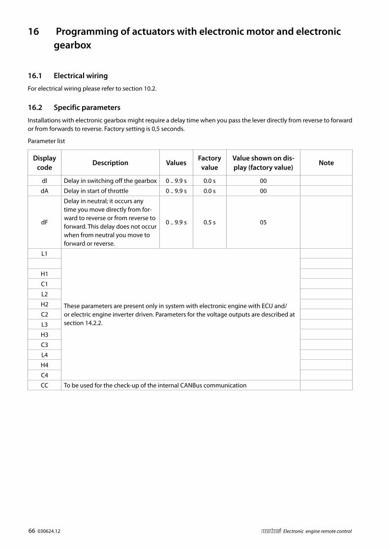
66 030624.12 vetus® Electronic engine remote control
16 Programming of actuators with electronic motor and electronic gearbox
16.1 Electrical wiring
For electrical wiring please refer to section 10.2.
16.2 Specific parameters
Installations with electronic gearbox might require a delay time when you pass the lever directly from reverse to forward or from forwards to reverse. Factory setting is 0,5 seconds.
Parameter list
Display code
Description ValuesFactory
valueValue shown on dis-play (factory value)
Note
dI Delay in switching off the gearbox 0 .. 9.9 s 0.0 s 00
dA Delay in start of throttle 0 .. 9.9 s 0.0 s 00
dF
Delay in neutral; it occurs any time you move directly from for-ward to reverse or from reverse to forward. This delay does not occur when from neutral you move to forward or reverse.
0 .. 9.9 s 0.5 s 05
L1
These parameters are present only in system with electronic engine with ECU and/or electric engine inverter driven. Parameters for the voltage outputs are described at section 14.2.2.
H1
C1
L2
H2
C2
L3
H3
C3
L4
H4
C4
CC To be used for the check-up of the internal CANBus communication

030624.12 67vetus® Electronic engine remote control
17 Programming of actuators with electronic CANBUS motor and me-chanical gearbox
17.1 Installation of the push-pull cable and programming of the cable stroke
Please refer to sections 9., 12. and 13.2.
17.2 Specific parameters
Display code
Description ValuesFactory
valueValue shown on dis-play (factory value)
Note
dI Delay in switching off the gearbox 0 .. 9.9 s 0.0 s 00
dA Delay in start of throttle 0 .. 9.9 s 0.0 s 00
dF
Delay in neutral; it occurs any time you move directly from for-ward to reverse or from reverse to forward. This delay does not occur when from neutral you move to forward or reverse.
0 .. 9.9 s 0.5 s 05
CP Canbus protocol 1-99 0 00 See 17.2.2.
CC CANBus communication - - -
17.2.1 CANBus protocolEvery CANBus interface card has one output. Communication starts automatically at power-up. This document refers to SAE J1939 CANBus protocol. The electronic system can handle also other communication pro-tocols.
Bit rate Repetition rate Identifier
29 bit in according to CAN 2.0B
default value default value description n° byte
250 Kbit/s 10 ms Priority 1
PGN 2
Address 1
Identifier:
Identifier Priority PGN Address
Hexadecimal values (_) 0x _ _ 0x _ _ _ _ 0x _ _
Data field
The 8 bytes of the Can Data Link are completely programmable according to the profile used by the motor producer. In the data field you must write the motor speed reference. Necessary information for majority of the motors are minimum speed and maximum speed without load.Byte 2 and byte 3 are used to transfer the speed reference. Bytes 1, 4, 5, 6, 7, 8 are commonly not used.

68 030624.12 vetus® Electronic engine remote control
17.2.2 Setting of the CANBus parameter values After the mechanical and electrical installation, it is necessary to set into the actuator the type of motor to command.
The procedure is the following:
• 1. when the actuator is powered up the display shows “ _ _”. Press at the same time keys “1” and “2” and automati-cally parameter A0 will appear on the display;
• 2. with keys “1” and “2” scroll the different parameters until you reach parameter CP;
• 3. after you have pressed “3” , the display start blinking and with the help of keys “1” and “2” you can set the value which is correct for your specific motor. Each motor is defined by a specific value which is listed in the table here below.
• 4. press “3” again to store the right CANBus profile value.
Type of motor
ModelMinimum
speed (RPM)
Maximum speed with load (RPM)
Maximum speed
without load (RPM)
CAN identi-fier
Value
S30 230S30 ENTM 23 750
4000 4400
TSC1-AE
01
S30 230 3500 3900 02
N40 250 N40 ENTM 25
600
2800 3200 03N60 370 N60 ENTM 37
N60 400 N60 ENTM 403000 3300 04
N60 450 N60 ENTM 45
N60 560 N60 ENTM 56 3000 3300 TSC1-VE 05
C78 300 C78 ENTM 30 2000 2300
TSC1-AE
06
C78 550 C78 ENTM 55 2600 2900 07
C13 500 C13 ENTM 50 2000 2300 06
C13 825 C13 ENTM 83 2400 2700
TSC1-VE
08
C78 300 C78 ENTM 30 2000 2300 09
C78 550 C78 ENTM 55 2600 2900 10
C13 500 C13 ENTM 50 2000 2300 09
C87 620 C87 ENTM 62 2400 2800 11
C87 380 C87 ENTM 38 2000 2300 9
C87 750 C87 ENTM 75 2600 2900 12
Speed reference % 0% 100% EEC2 50
17.2.3 Technical data of the CANBus interface card
Maximum speed which each channel can generate is 100 mA. Each channel output is protected against short circuit towards ground and towards voltage supply. Termination resistor is already mounted on the CANBus interface card but it can be removed, if necessary.The CANBus interface card pin-out is described at section 5.5.5.
17.2.4 Wiring of the outgoing actuator cables
Please refer to section 10.2.

030624.12 69vetus® Electronic engine remote control
17.3 Connection to VF motors through CANBus interface
Common-rail VF motors with CANBus interface are equipped from factory with a 6 poles Superseal connector labelled JD. Standard procedure is to simply connect the throttle CANBus cable to connector JD.In case the motor doesn’t respond correctly to the command station, typical case is the motor that doesn’t’ accelerate regularly, make at the following controls:
• Operation to be done with the electronic control switched off: verify with a multimeter that the impedance between terminals JP4.4 and JP4.5 of the CANBus PCBoards on the actuator is = 60 ohm or similar (see section 5.4.4.). In case of different values, contact either Flexball or the VF dealer.
• Verify that the setting of the CANBUS CONVERTER MODULE is correct. The CANBUS CONVERTER MODULE is part of VF installation equipment and it is described by VF Norm A049. Dip switch n° 4 on the APEM connector must be set to OFF, like in the picture here below. If the dip switch of the CONVERTER MODULE is set to ON, it is impossible to accelerate the motor smoothly.
For more information look at VF Norm A049 and at the Application Note 3 – Installation on VF motors with CANBus inter-face dated 2009/10/11.
ON = the command from electronic control lever is disables (it doesn’t work properly)
OFF = the command from electronic control lever is enabled (it works properly)

70 030624.12 vetus® Electronic engine remote control
18 Programming of actuators with electronic CANBUS motor and electronic gearbox
18.1 CANBus motor parameters
For parameter setting, please refer to section 17.2.
18.2 Electronic gearbox parameters
For parameter setting, please refer to section 15.2.
18.3 Wiring of the actuator outgoing cables
For wiring of the cables outgoing from the actuator refer to section 10.2.

030624.12 71vetus® Electronic engine remote control
19 Programming of actuators for installations with Trim or Flap com-mand option
For trim or flap option it isn’t necessary any programming. Refer to the specific instructions for the actuators configured for their basic installation (without the trim option), as described in sections from 13. to 18. included.
Use electrical cables between actuator and trim pump or from actuator and flap pump as specified in sections 6.4, 6.5. and 10.2.2. Verify that wiring is according to electrical scheme reported at section 10.2.3.

72 030624.12 vetus® Electronic engine remote control
20 Programming of the Trolling functions
This chapter is dedicated to the specific parameters for setting up the trolling functionalities: for general programming of the actuator please refer to chapter 11.
20.1 Trolling actuator parameters
Flexball actuator for trolling control permits to adapt to every trolling valve system by correctly modifying a specific set of parameters, which are listed in the following table.
Important note: don’t modify these parameter unless you have completely understood their meaning and the trolling valve system. Personal injury and mechanical/electrical damages may occur!
Parameter / display code
Min Max Def Unit Description
t0 0 99 14 % PWM % @ minimum trolling speed
t1 0 99 21 % PWM % @ maximum trolling speed
t2 0 99 0 % PWM % during propeller start
t3 0 99 10 s/10 propeller start’s time span
t4 0 99 0 % RPM Engine % increment (related to minimum engine speed) reached @ maximum trolling speed
t5 0 1 0 - Trolling active signaling output:• 0: outputsareVbatterywhentrollingisactive,floating
otherwise• 1: outputsarefloatingwhentrollingisactive,Vbattery
when not active
t6 0 99 0 % Trolling valves PWM % when trolling is not active
t7 0 99 0 % RPM Engine % increment (related to minimum engine speed) maintained after trolling speed ramp
t8 0 99 0 - Reserved
t9 0 99 0 - Reserved
Parameter “t0”
This parameter defines the PWM percentage applied to the trolling valve when trolling is maximum (100%).It determines the minimum propeller speed. Default value on ZF trolling systems is 14%. (VERIFICARE).
Parameter “t1”
This parameter defines the PWM percentage applied to the trolling valve when trolling is minimum (0%).It determines the maximum propeller speed at the end of the trolling ramp. Default value on ZF trolling systems is 23%. (VERIFICARE).
Parameter “t2”
In order to reduce the time to start the boat, it might be necessary to give a quick “kick-off”, Parameters “t2” and “t3” permit to apply a for a limited time (t3) a higher speed on the propeller. “t3” defines the percentage to be applied for a defined amount of time, before entering in trolling mode.
Parameter “t3”
It defines for how much time can be applied the “kick-off” before entering in trolling mode.
Parameter “t4”
In some application it might be useful to slightly change the motor speed during the trolling ramp. When motor is idling,

030624.12 73vetus® Electronic engine remote control
motor speed could be at its mini-mum. When the gear is engaged, it might be necessary to slightly in-crease the motor RPM to compen-sate an increase of the increased load of the shft + propeller, which are now clutched together with the motor. At the end of trolling ramp engine will reach the value imposed with this parameter: during trolling ramp the engine’s speed will vary proportionally from “native“ minimum speed to the one defines by parameter t4.
Important note: don’t ex-ceed the maximum input speed for your trolling valve system! Check care-fully its technical data and set t4 correctly!
Parameter “t5”
Trolling management board has one digital output that is activated when trolling mode is active. This parameter defines how will work this output:
• 0 : outputs are connected to voltage battery when trolling is active, floating otherwise;
• 1 : outputs are floating when trolling is active, connected to voltage battery when trolling isn’t active.
This feature is not used currently.
Parameter “t6”
Trolling valves PWM % when trolling is not active.
Parameter “t7”
When trolling is activated, this parameter defines the minimum engine’s RPM at the end of trolling speed ramp. When trolling is activated, if you set t4 equal to t7 no discontinuity will occur passing through trolling ramp zone and accelera-tion zone. Parameter t7 as no meaning out of trolling mode.
Important note: don’t exceed the maximum input speed for your trolling valve system! Check carefully cor-responding technical data and set t7 correctly!
16° 32° 80°
0 t2
t2t0t6
t1
t0t6
16° 32° 80°
100%
t4
0%
t7
Time
Lever angle
Lever angle
Enginethrottle
PWM(current)
PWM(current)

74 030624.12 vetus® Electronic engine remote control
21 Behaviour of the electronic system in case of failures
21.1 Unforeseen motor switching off
In any case where the motor switches off during navigation, the normal procedure requires to turn off the ignition key and then to turn it on again. During the turn-on operation, independently on the position of the command station, the actuator behaves as follows:
• Gearbox is moved to a the safety position (neutral)
• Motor accelerator is moved to minimum
The command station that had the control of the vessel, has now lost the command. In order to acquire the command again, you must start again the procedure:
• put the lever in neutral
• press “Command” and then “Warm-up”.
This procedure is described in section 3
21.2 Faults in the electrical network
In case of system fault (missing power supply, data transmission cables broken, etc) if the vessel is equipped with me-chanical actuators, it can be controlled via emergency levers. See the procedure ‘Emergency levers’ in section 3.6. of this manual.
21.3 Protection in case of overload or break of the push-pull cables
The actuator has a built-in control that generates a failure alarm, in case the push-pull cables becomes “too hard” or in case the cable stroke is not set correctly (beyond the maximum stroke allowed by the actuator).If one of the above mentioned cases occurs:
• the systems stops (no movements on the push-pull cables)
• on the display of the actuator appears an “E” on the side of the overloaded cable
• all the LEDs of the command stations start to blink.
An “E” will be shown on theside of the actuator with thecable overload
An “E” will be shown on theside of the actuator with the
cable overload
In case this alarm is activated, turn off the system, verify the causes that have generated the alarm before turning on again the system.

030624.12 75vetus® Electronic engine remote control
21.4 Troubleshooting
Irregularity What to check Section to refer
Command station is activated and without moving the lever, the actuator generates movements, changes speed of activates the gear
• 2 command stations have the same CANBus address
Section 4.4. e chapters 7., 8.• It is missing the end of line bus
termination
Station doesn’t take the commandCheck that end of line resistance terminations have been activated
Section 4.4. and chapters 7., 8.
The motor doesn’t accelerate (installa-tions with FPT motors)
Check the setting of the dip-switches on the CANBUS CONVERT-ER MODULE.
Section 17.4.
On installations with mechanical actuators when you move forward the command lever, the actuator generates a reverse movement
Modify parameter A0 Section 14.2.1.
Minimum speed position on the com-mand stations corresponds to maximum speed on the actuator
• Check that throttle positions are according to the scheme
• Scheme at section 13.2 or 15.1
• Check settings of parameter A0 • Section 14.2.1

76 030624.12 vetus® Electronic engine remote control
21.5 LED diagnosis on command station
Command station produces signals to show either the operating conditions or possible causes of irregularities.
LED indicationsWhen it
happensMeaning/problem What to do
1° flash long and 2° flash long
Power up
Command station configured for installations with 1 motor
If you need to reconfigure the command station see section 4.3
1° flash short and 2° flash long
Command station configured for installations with 2 motors and 1 actuator
1° flash short and 2° flash short
Command station configured for installations with 2 motors and 2 actuators
2 LED green with fixed light
After power up
Gearbox command is in neutral, the installation works correctly
-
On the command station don’t light on either 1 or 2 green LED
• Power supply is missing
• In installation with push-pull ca-bles, the gearbox hasn’t come to neutral position
• Check on the actuator that the display is enlightened
• Check and remove the obsta-cle which don’t let the actua-tor go to neutral position (see sections 3.6. and 21.3.)
Green LED on command stations is blinking (90% ON, 10% OFF)
Command station is not configured correctly wilt respect to the type of installation; command station has been configured for installa-tions with 1 actuator and it must be configured for installations with 2 actuators
Reconfigure command station as described at section 4.3.
Green LED on command station is blinking (50% ON, 50% OFF)
Might be a problem on the posi-tioning measuring device of the command station
Contact Vetus
All 4 LEDs are blinkingThere is a failure on mechanical actuators, probably due to an extra load on push-pull cables
To remove the failure refers at section 21.3.

030624.12 77vetus® Electronic engine remote control
22 How to start
Once you have received the system package, follow these steps:
1) identify all the components necessary to build up your system with the help of instructions at sections 4,5,6
2) identify your installation type with the help of section 7.
3) configure the CANBus network, set dip-switches and end of line termination of actuators and command stations, as described at section 8
4) mount command stations and actuators with the help of drill pattern (section 23)
5) make electrical wiring (section 10)
6) install push-pull cables, if your application requires it (section 9)
7) make setting of mechanical strokes, if your application requires it (section 12)
8) program the actuator specific installation parameters (from section 13 to section 18 included)
9) make the programming of the options, if your application requires it (sections 19 and 20)
10) once you have set-up the electronic system, read the pilot instruction (section 3) and, good navigation!
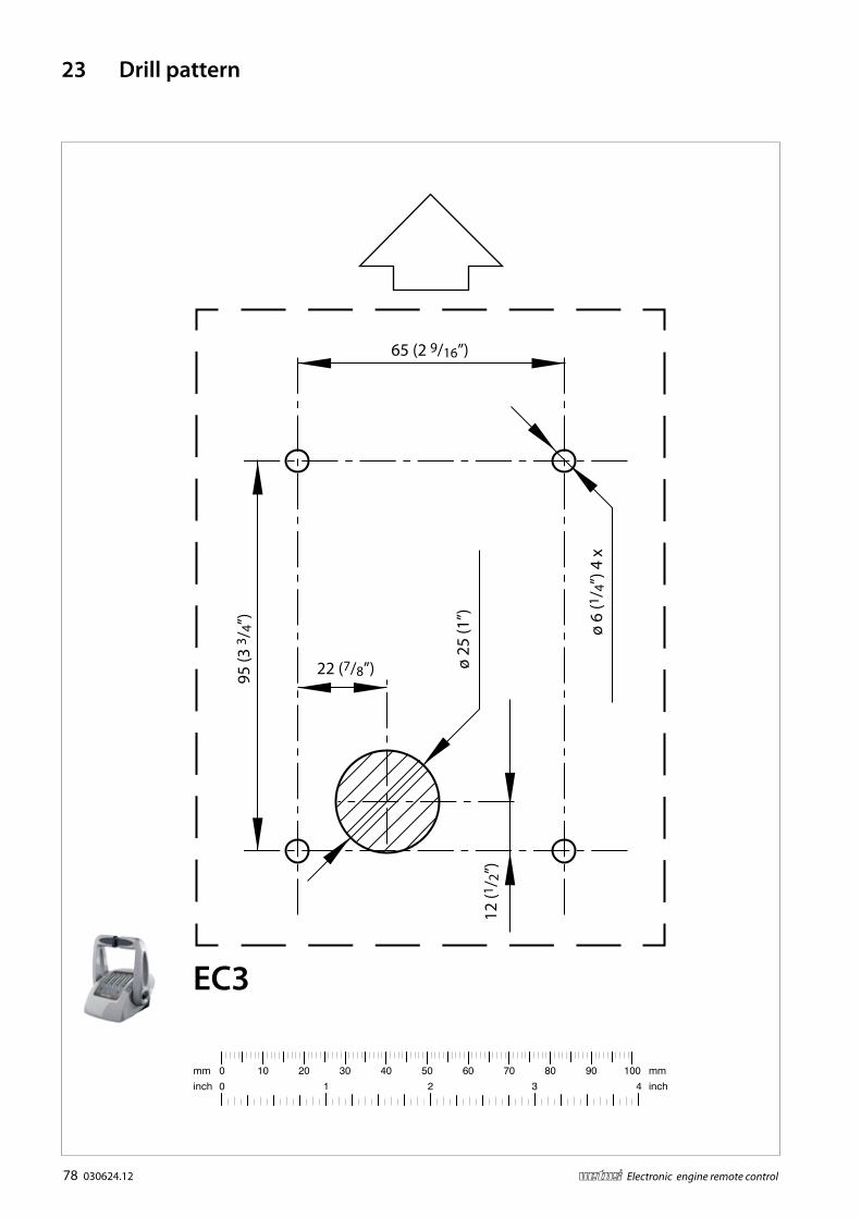
78 030624.12 vetus® Electronic engine remote control
23 Drill pattern
65 (2 9/16”)
95 (3
3/ 4
”)
22 (7/8”)
12 (1
/ 2”)
ø 25
(1”)
ø 6
(1/ 4
”) 4
x
EC3

030624.12 79vetus® Electronic engine remote control
ø 6 (1/4”) 4 x
EC4
74 (2 15/16”)
76.5 (3”)
134
.5 (5
5/ 1
6”)
11
(7/ 1
6”)
121
(4 3
/ 4”)

80 030624.12 vetus® Electronic engine remote control
180
(7 3
/ 32”
)
ø 6,2 (1/4”) 4 x
280 (11”)
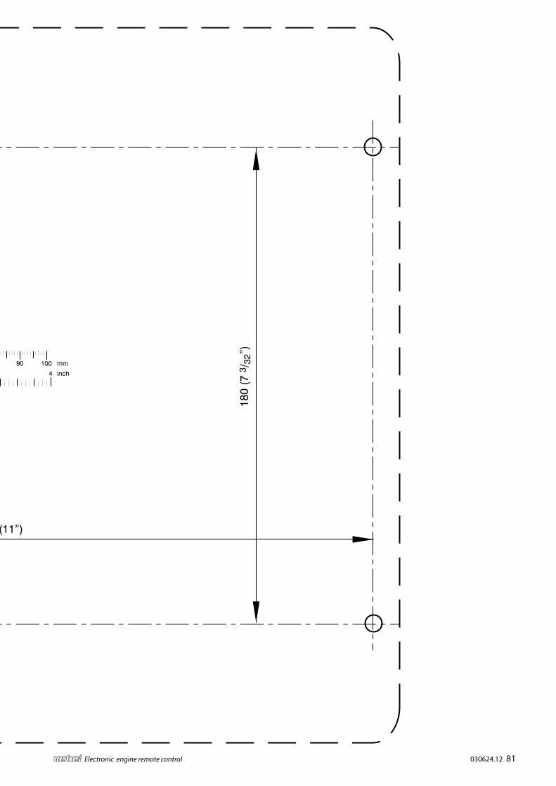
030624.12 81vetus® Electronic engine remote control
180
(7 3
/ 32”
)
ø 6,2 (1/4”) 4 x
280 (11”)

82 030624.12 vetus® Electronic engine remote control

030624.12 83vetus® Electronic engine remote control

vetus b.v.FOKKERSTRAAT 571 - 3125 BD SCHIEDAM - HOLLAND - TEL.: +31 10 4377700TELEFAX: +31 10 4372673 - 4621286 - E-MAIL: [email protected] - INTERNET: http://www.vetus.com
Printed in the Netherlands030624.12 2013-08