Embed Size (px)
Citation preview
ASIC Based Closed-Loop Transducersfrom 6 A up to 25 A nominal
TechnicalInformation
Electronic Components
2
ASIC
IN
Closed-loop principle
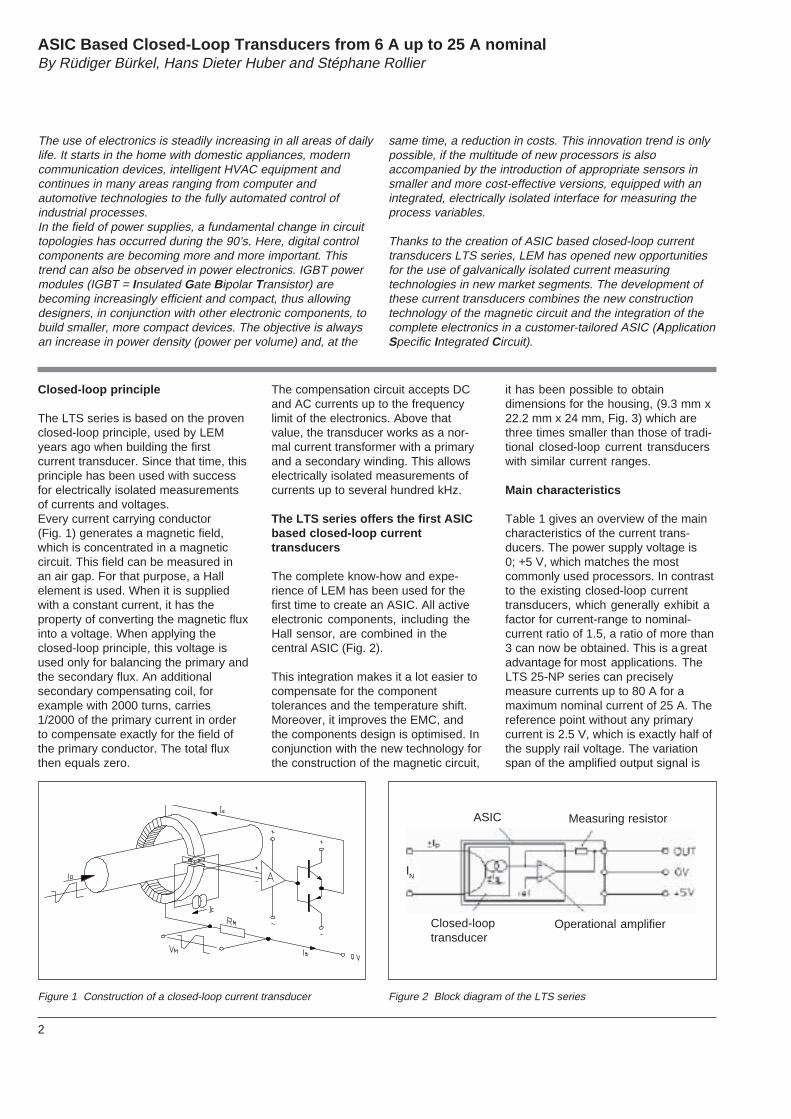
The LTS series is based on the provenclosed-loop principle, used by LEMyears ago when building the firstcurrent transducer. Since that time, thisprinciple has been used with successfor electrically isolated measurementsof currents and voltages.Every current carrying conductor(Fig. 1) generates a magnetic field,which is concentrated in a magneticcircuit. This field can be measured inan air gap. For that purpose, a Hallelement is used. When it is suppliedwith a constant current, it has theproperty of converting the magnetic fluxinto a voltage. When applying theclosed-loop principle, this voltage isused only for balancing the primary andthe secondary flux. An additionalsecondary compensating coil, forexample with 2000 turns, carries1/2000 of the primary current in orderto compensate exactly for the field ofthe primary conductor. The total fluxthen equals zero.
The compensation circuit accepts DCand AC currents up to the frequencylimit of the electronics. Above thatvalue, the transducer works as a nor-mal current transformer with a primaryand a secondary winding. This allowselectrically isolated measurements ofcurrents up to several hundred kHz.
The LTS series offers the first ASICbased closed-loop currenttransducers
The complete know-how and expe-rience of LEM has been used for thefirst time to create an ASIC. All activeelectronic components, including theHall sensor, are combined in thecentral ASIC (Fig. 2).
This integration makes it a lot easier tocompensate for the componenttolerances and the temperature shift.Moreover, it improves the EMC, andthe components design is optimised. Inconjunction with the new technology forthe construction of the magnetic circuit,
it has been possible to obtaindimensions for the housing, (9.3 mm x22.2 mm x 24 mm, Fig. 3) which arethree times smaller than those of tradi-tional closed-loop current transducerswith similar current ranges.
Main characteristics
Table 1 gives an overview of the maincharacteristics of the current trans-ducers. The power supply voltage is0; +5 V, which matches the mostcommonly used processors. In contrastto the existing closed-loop currenttransducers, which generally exhibit afactor for current-range to nominal-current ratio of 1.5, a ratio of more than3 can now be obtained. This is a greatadvantage for most applications. TheLTS 25-NP series can preciselymeasure currents up to 80 A for amaximum nominal current of 25 A. Thereference point without any primarycurrent is 2.5 V, which is exactly half ofthe supply rail voltage. The variationspan of the amplified output signal is
ASIC Based Closed-Loop Transducers from 6 A up to 25 A nominalBy Rüdiger Bürkel, Hans Dieter Huber and Stéphane Rollier
The use of electronics is steadily increasing in all areas of dailylife. It starts in the home with domestic appliances, moderncommunication devices, intelligent HVAC equipment andcontinues in many areas ranging from computer andautomotive technologies to the fully automated control ofindustrial processes.In the field of power supplies, a fundamental change in circuittopologies has occurred during the 90’s. Here, digital controlcomponents are becoming more and more important. Thistrend can also be observed in power electronics. IGBT powermodules (IGBT = Insulated Gate Bipolar Transistor) arebecoming increasingly efficient and compact, thus allowingdesigners, in conjunction with other electronic components, tobuild smaller, more compact devices. The objective is alwaysan increase in power density (power per volume) and, at the
same time, a reduction in costs. This innovation trend is onlypossible, if the multitude of new processors is alsoaccompanied by the introduction of appropriate sensors insmaller and more cost-effective versions, equipped with anintegrated, electrically isolated interface for measuring theprocess variables.
Thanks to the creation of ASIC based closed-loop currenttransducers LTS series, LEM has opened new opportunitiesfor the use of galvanically isolated current measuringtechnologies in new market segments. The development ofthese current transducers combines the new constructiontechnology of the magnetic circuit and the integration of thecomplete electronics in a customer-tailored ASIC (ApplicationSpecific Integrated Circuit).
Figure 1 Construction of a closed-loop current transducer Figure 2 Block diagram of the LTS series
Measuring resistor
Operational amplifierClosed-looptransducer
3
-15V
R
M
-5V 0 V
I
I
A/DI
I
+15 V +5 V +5 V
E DSP/µPRM
-15 V -5 V 0 V
-15V
R
M
0 V
DS P
oder
P
A /D
I
I
A/D DSP/µPRMI
I
+15 V +5 V
-15 V 0 V
0.625 V/IPN, which results in an outputvoltage of 4.5 V at +80 A and 0.5 V at-80 A (e.g. LTS 25-NP). The currenttransducers also meet the usualstandards for Power ElectronicsSystems.
Excellent accuracy and temperaturestability
The series LTS current transducersachieve a total accuracy better than
±0.2 % at 25 °C. This value includesall kinds of transducer specifictolerances, such as linearity errors,error of the number of turns and effectson the long-term stability.
In contrast to the majority of closed-loop current transducers available inthe market today, which generallyhave a current output, here the mea-suring resistor has been integrated intothe transducer. LEM has chosenresistors with an accuracy of
±0.5 % and a temperature drift of50 ppm/K maximum.The built-in reference, which is alsonew, reaches a temperature stability of100 ppm/K max. The absoluteaccuracy of the reference is notimportant since, in most cases, it canbe compensated by a processor.
By adding up all tolerances in a tem-perature range from -10 °C to +85 °C,the following accuracy is obtained forthe LTS series for ∆T = 60 K:
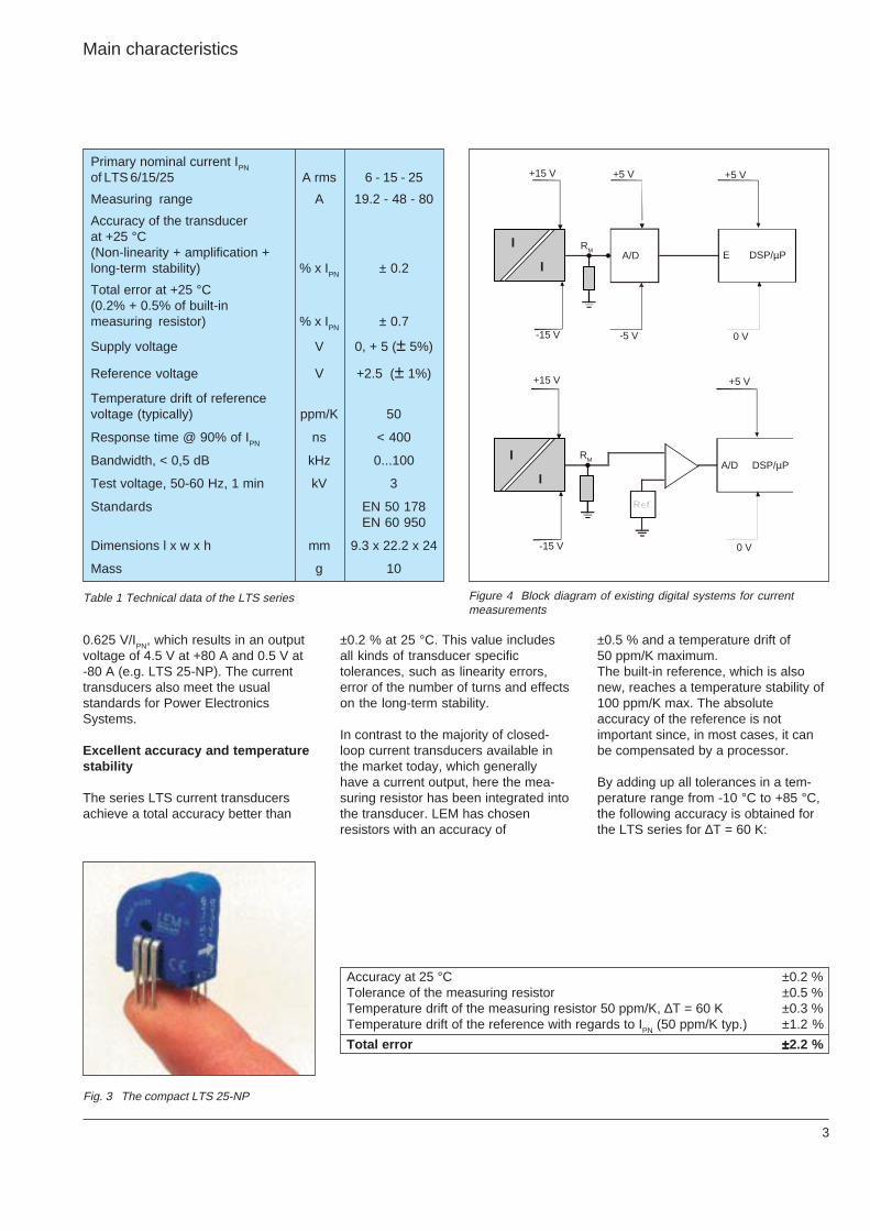
Main characteristics
Primary nominal current IPN
of LTS 6/15/25 A rms 6 - 15 - 25
Measuring range A 19.2 - 48 - 80
Accuracy of the transducerat +25 °C(Non-linearity + amplification +long-term stability) % x IPN ± 0.2
Total error at +25 °C(0.2% + 0.5% of built-inmeasuring resistor) % x IPN ± 0.7
Supply voltage V 0, + 5 (± 5%)
Reference voltage V +2.5 (± 1%)
Temperature drift of referencevoltage (typically) ppm/K 50
Response time @ 90% of IPN ns < 400
Bandwidth, < 0,5 dB kHz 0...100
Test voltage, 50-60 Hz, 1 min kV 3
Standards EN 50 178EN 60 950
Dimensions l x w x h mm 9.3 x 22.2 x 24
Mass g 10
Table 1 Technical data of the LTS series Figure 4 Block diagram of existing digital systems for currentmeasurements
Accuracy at 25 °C ±0.2 %Tolerance of the measuring resistor ±0.5 %Temperature drift of the measuring resistor 50 ppm/K, ∆T = 60 K ±0.3 %Temperature drift of the reference with regards to IPN (50 ppm/K typ.) ±1.2 %
Total error ±±±±±2.2 %
Fig. 3 The compact LTS 25-NP
4
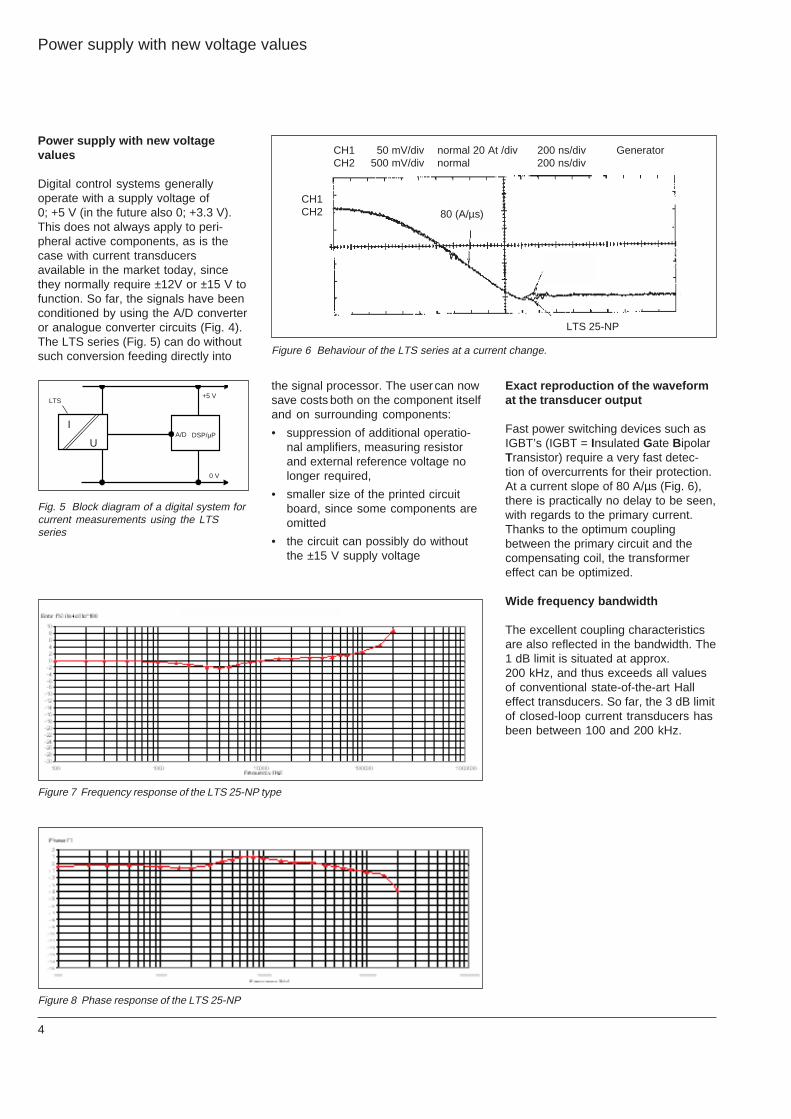
CH1 50 mV/div normal 20 At /div 200 ns/div GeneratorCH2 500 mV/div normal 200 ns/div
CH1CH2
LTS 25-NP
DSP/µPA/DI
LTS+5 V
0 V
U
80 (A/µs)
Power supply with new voltagevalues
Digital control systems generallyoperate with a supply voltage of0; +5 V (in the future also 0; +3.3 V).This does not always apply to peri-pheral active components, as is thecase with current transducersavailable in the market today, sincethey normally require ±12V or ±15 V tofunction. So far, the signals have beenconditioned by using the A/D converteror analogue converter circuits (Fig. 4).The LTS series (Fig. 5) can do withoutsuch conversion feeding directly into
Exact reproduction of the waveformat the transducer output
Fast power switching devices such asIGBT’s (IGBT = Insulated Gate BipolarTransistor) require a very fast detec-tion of overcurrents for their protection.At a current slope of 80 A/µs (Fig. 6),there is practically no delay to be seen,with regards to the primary current.Thanks to the optimum couplingbetween the primary circuit and thecompensating coil, the transformereffect can be optimized.
Wide frequency bandwidth
The excellent coupling characteristicsare also reflected in the bandwidth. The1 dB limit is situated at approx.200 kHz, and thus exceeds all valuesof conventional state-of-the-art Halleffect transducers. So far, the 3 dB limitof closed-loop current transducers hasbeen between 100 and 200 kHz.
Power supply with new voltage values
the signal processor. The user can nowsave costs both on the component itselfand on surrounding components:
• suppression of additional operatio-nal amplifiers, measuring resistorand external reference voltage nolonger required,
• smaller size of the printed circuitboard, since some components areomitted
• the circuit can possibly do withoutthe ±15 V supply voltage
Fig. 5 Block diagram of a digital system forcurrent measurements using the LTSseries
Figure 7 Frequency response of the LTS 25-NP type
Figure 8 Phase response of the LTS 25-NP
Figure 6 Behaviour of the LTS series at a current change.
5
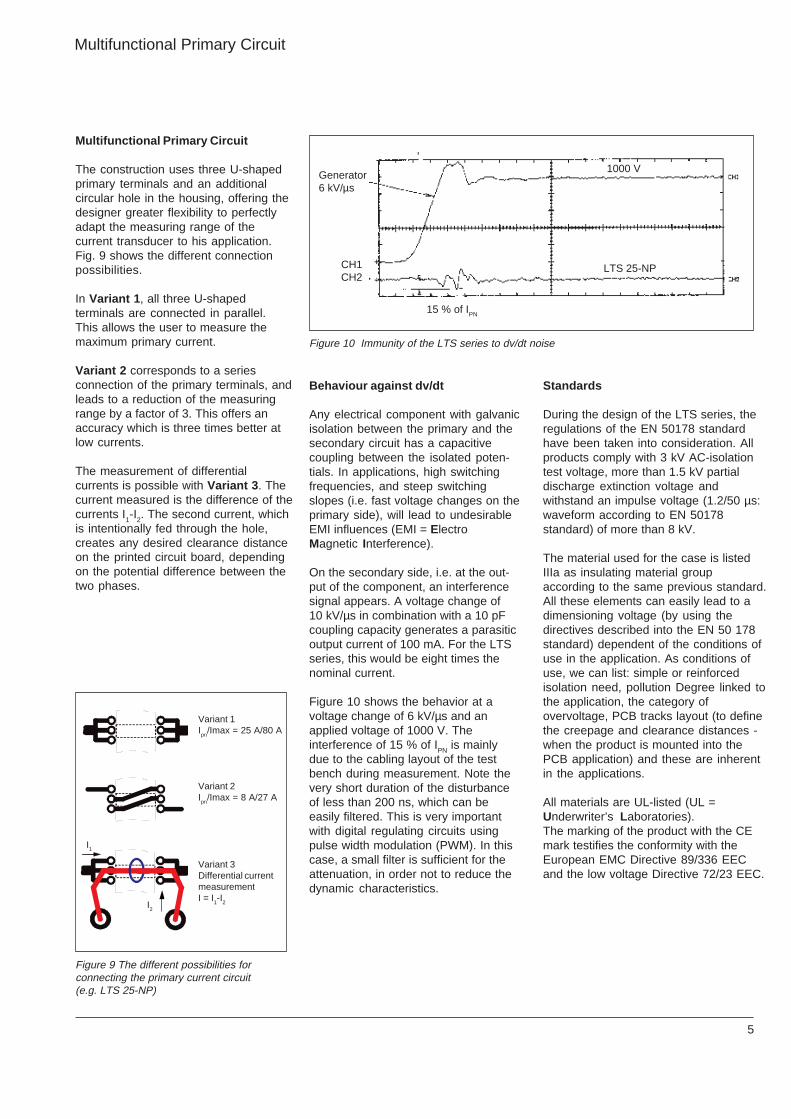
Generator6 kV/µs
CH1CH2
LTS 25-NP
1000 V
15 % of IPN
I1
I2
Multifunctional Primary Circuit
The construction uses three U-shapedprimary terminals and an additionalcircular hole in the housing, offering thedesigner greater flexibility to perfectlyadapt the measuring range of thecurrent transducer to his application.Fig. 9 shows the different connectionpossibilities.
In Variant 1, all three U-shapedterminals are connected in parallel.This allows the user to measure themaximum primary current.
Variant 2 corresponds to a seriesconnection of the primary terminals, andleads to a reduction of the measuringrange by a factor of 3. This offers anaccuracy which is three times better atlow currents.
The measurement of differentialcurrents is possible with Variant 3. Thecurrent measured is the difference of thecurrents I1-I2. The second current, whichis intentionally fed through the hole,creates any desired clearance distanceon the printed circuit board, dependingon the potential difference between thetwo phases.
Standards
During the design of the LTS series, theregulations of the EN 50178 standardhave been taken into consideration. Allproducts comply with 3 kV AC-isolationtest voltage, more than 1.5 kV partialdischarge extinction voltage andwithstand an impulse voltage (1.2/50 µs:waveform according to EN 50178standard) of more than 8 kV.
The material used for the case is listedIIIa as insulating material groupaccording to the same previous standard.All these elements can easily lead to adimensioning voltage (by using thedirectives described into the EN 50 178standard) dependent of the conditions ofuse in the application. As conditions ofuse, we can list: simple or reinforcedisolation need, pollution Degree linked tothe application, the category ofovervoltage, PCB tracks layout (to definethe creepage and clearance distances -when the product is mounted into thePCB application) and these are inherentin the applications.
All materials are UL-listed (UL =Underwriter’s Laboratories).The marking of the product with the CEmark testifies the conformity with theEuropean EMC Directive 89/336 EECand the low voltage Directive 72/23 EEC.
Behaviour against dv/dt
Any electrical component with galvanicisolation between the primary and thesecondary circuit has a capacitivecoupling between the isolated poten-tials. In applications, high switchingfrequencies, and steep switchingslopes (i.e. fast voltage changes on theprimary side), will lead to undesirableEMI influences (EMI = ElectroMagnetic Interference).
On the secondary side, i.e. at the out-put of the component, an interferencesignal appears. A voltage change of10 kV/µs in combination with a 10 pFcoupling capacity generates a parasiticoutput current of 100 mA. For the LTSseries, this would be eight times thenominal current.
Figure 10 shows the behavior at avoltage change of 6 kV/µs and anapplied voltage of 1000 V. Theinterference of 15 % of IPN is mainlydue to the cabling layout of the testbench during measurement. Note thevery short duration of the disturbanceof less than 200 ns, which can beeasily filtered. This is very importantwith digital regulating circuits usingpulse width modulation (PWM). In thiscase, a small filter is sufficient for theattenuation, in order not to reduce thedynamic characteristics.
Multifunctional Primary Circuit
Figure 9 The different possibilities forconnecting the primary current circuit(e.g. LTS 25-NP)
Figure 10 Immunity of the LTS series to dv/dt noise
Variant 1Ipn
/Imax = 25 A/80 A
Variant 2Ipn
/Imax = 8 A/27 A
Variant 3Differential currentmeasurementI = I
1-I
2
6
M
Practical examples
1. Electrically isolated currentmeasurements on a converter
The LTS series is open to allapplications in low-power electronicsystems. A typical application field isthe classic frequency inverter. Due toits excellent accuracy and immunity todv/dt noise, it is ideally suited for servo-drive applications.
Figure 11 gives an overview of thevarious possibilities of electricallyisolated current measurements.
Advantages
• excellent linearity for exactmeasurements of the motor currents
• fast response for obtaining shortswitch-off times in case of a faultcondition, such as an earth leakageor a short circuit,
• good temperature stability allowsprecise repeatable measurements,
• immunity to high capacitive currentchanges which can result from longmotor cables.
2. Use in vehicles
For the use in vehicles (electricvehicles, fork lift trucks, cars etc.) withvoltages up to approx. 80 V, theelectrical isolation performance is notimportant. Here, other productadvantages are more decisive:
• construction meets requirements ofpick-and-place machines for PCB’s
• high availability, as only one activecomponent is integrated,
• the component is fully potted andthus immune to environmentalinfluences.
3. General current monitoring andregulation
The application possibilities are many:Where currents have to be preciselydetected, regulated and monitored, theLTS series offers possibilities which,perhaps, have not been seriouslyconsidered yet. This applies especiallyto systems in which, until now, only thealternating current has been measured.Non-linear loads are increasinglygenerating non-sinusoidal waveforms,which contain DC currents. The LTSseries offers a good alternative to theclassic transformers, because they canmeasure both DC and AC currentswith the same device.
It can also be used in DC devices suchas power supplies, battery-poweredequipment or DC drives.In this case, the LTS series offers thefollowing advantages over a shuntresistor:
• much lower power losses,
• electrical isolation,
• better EMI immunity.
Figure 11: Possibilities of electrically isolated current measurements using the LTS series inan inverter
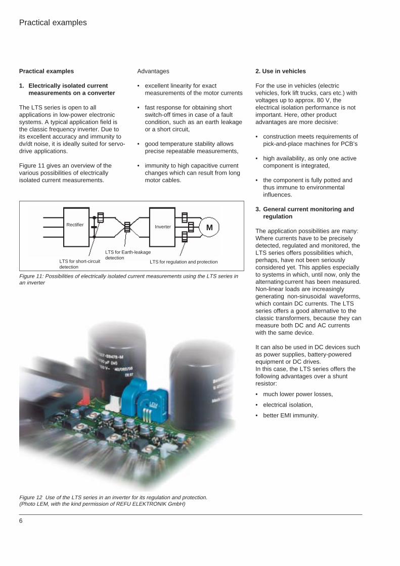
Figure 12 Use of the LTS series in an inverter for its regulation and protection.(Photo LEM, with the kind permission of REFU ELEKTRONIK GmbH)
Practical examples
Rectifier Inverter
LTS for short-circuitdetection
LTS for regulation and protection
LTS for Earth-leakagedetection
7
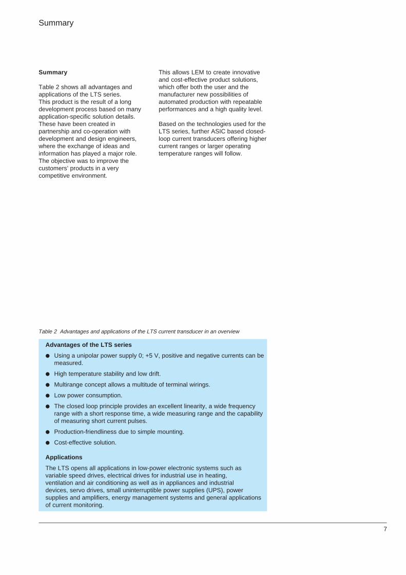
Advantages of the LTS series
Using a unipolar power supply 0; +5 V, positive and negative currents can bemeasured.
High temperature stability and low drift.
Multirange concept allows a multitude of terminal wirings.
Low power consumption.
The closed loop principle provides an excellent linearity, a wide frequencyrange with a short response time, a wide measuring range and the capabilityof measuring short current pulses.
Production-friendliness due to simple mounting.
Cost-effective solution.
Applications
The LTS opens all applications in low-power electronic systems such asvariable speed drives, electrical drives for industrial use in heating,ventilation and air conditioning as well as in appliances and industrialdevices, servo drives, small uninterruptible power supplies (UPS), powersupplies and amplifiers, energy management systems and general applicationsof current monitoring.
Table 2 Advantages and applications of the LTS current transducer in an overview
Summary
Table 2 shows all advantages andapplications of the LTS series.This product is the result of a longdevelopment process based on manyapplication-specific solution details.These have been created inpartnership and co-operation withdevelopment and design engineers,where the exchange of ideas andinformation has played a major role.The objective was to improve thecustomers’ products in a verycompetitive environment.
Summary
This allows LEM to create innovativeand cost-effective product solutions,which offer both the user and themanufacturer new possibilities ofautomated production with repeatableperformances and a high quality level.
Based on the technologies used for theLTS series, further ASIC based closed-loop current transducers offering highercurrent ranges or larger operatingtemperature ranges will follow.
8
991001
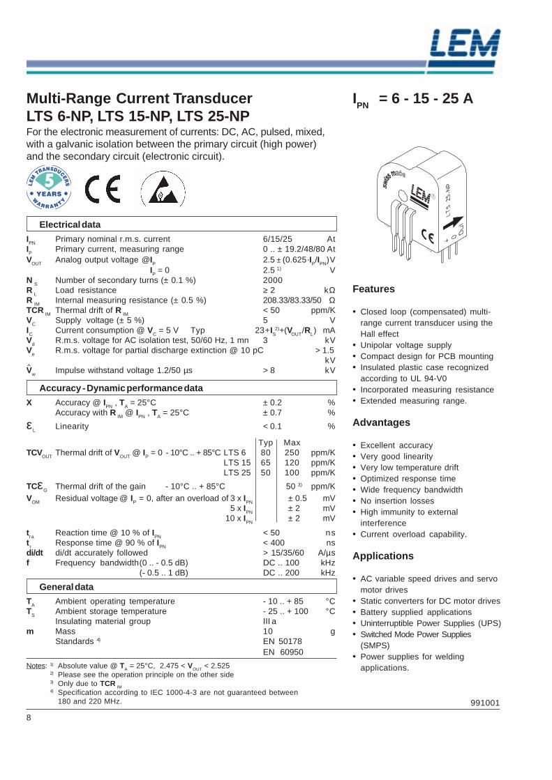
IPN = 6 - 15 - 25 AMulti-Range Current TransducerLTS 6-NP, LTS 15-NP, LTS 25-NPFor the electronic measurement of currents: DC, AC, pulsed, mixed,with a galvanic isolation between the primary circuit (high power)and the secondary circuit (electronic circuit).
Electrical data
IPN Primary nominal r.m.s. current 6/15/25 AtIP Primary current, measuring range 0 .. ± 19.2/48/80 AtVOUT Analog output voltage @IP 2.5 ± (0.625·IP/IPN)V
IP = 0 2.5 1) VN S Number of secondary turns (± 0.1 %) 2000R L Load resistance ≥ 2 kΩR IM Internal measuring resistance (± 0.5 %) 208.33/83.33/50 ΩTCR IM Thermal drift of R IM < 50 ppm/KVC Supply voltage (± 5 %) 5 VIC Current consumption @ VC = 5 V Typ 23 + IS
2) + (VOUT/RL) mA
Vd R.m.s. voltage for AC isolation test, 50/60 Hz, 1 mn 3 kVVe R.m.s. voltage for partial discharge extinction @ 10 pC > 1.5
kVVw Impulse withstand voltage 1.2/50 µs > 8 kV
Accuracy - Dynamic performance data
X Accuracy @ IPN , TA = 25°C ± 0.2 %Accuracy with R IM @ IPN , TA = 25°C ± 0.7 %
εL Linearity < 0.1 %
Typ MaxTCVOUT Thermal drift of VOUT @ IP = 0 - 10°C .. + 85°C LTS 6 80 250 ppm/K
LTS 15 65 120 ppm/KLTS 25 50 100 ppm/K
TCεG Thermal drift of the gain - 10°C .. + 85°C 50 3) ppm/KVOM Residual voltage @ IP = 0, after an overload of 3 x IPN ± 0.5 mV
5 x IPN ± 2 mV10 x IPN ± 2 mV
tra Reaction time @ 10 % of IPN < 50 nstr Response time @ 90 % of IPN < 400 nsdi/dt di/dt accurately followed > 15/35/60 A/µsf Frequency bandwidth(0 .. - 0.5 dB) DC .. 100 kHz
(- 0.5 .. 1 dB) DC .. 200 kHz
General data
TA Ambient operating temperature - 10 .. + 85 °CTS Ambient storage temperature - 25 .. + 100 °C
Insulating material group III am Mass 10 g
Standards 4) EN 50178EN 60950
Notes: 1) Absolute value @ TA = 25°C, 2.475 < VOUT < 2.5252) Please see the operation principle on the other side3) Only due to TCR IM4) Specification according to IEC 1000-4-3 are not guaranteed between
180 and 220 MHz.
Features
• Closed loop (compensated) multi-range current transducer using theHall effect
• Unipolar voltage supply• Compact design for PCB mounting• Insulated plastic case recognized
according to UL 94-V0• Incorporated measuring resistance• Extended measuring range.
Advantages
• Excellent accuracy• Very good linearity• Very low temperature drift• Optimized response time• Wide frequency bandwidth• No insertion losses• High immunity to external
interference• Current overload capability.
Applications
• AC variable speed drives and servomotor drives
• Static converters for DC motor drives• Battery supplied applications• Uninterruptible Power Supplies (UPS)• Switched Mode Power Supplies
(SMPS)• Power supplies for welding
applications.
9
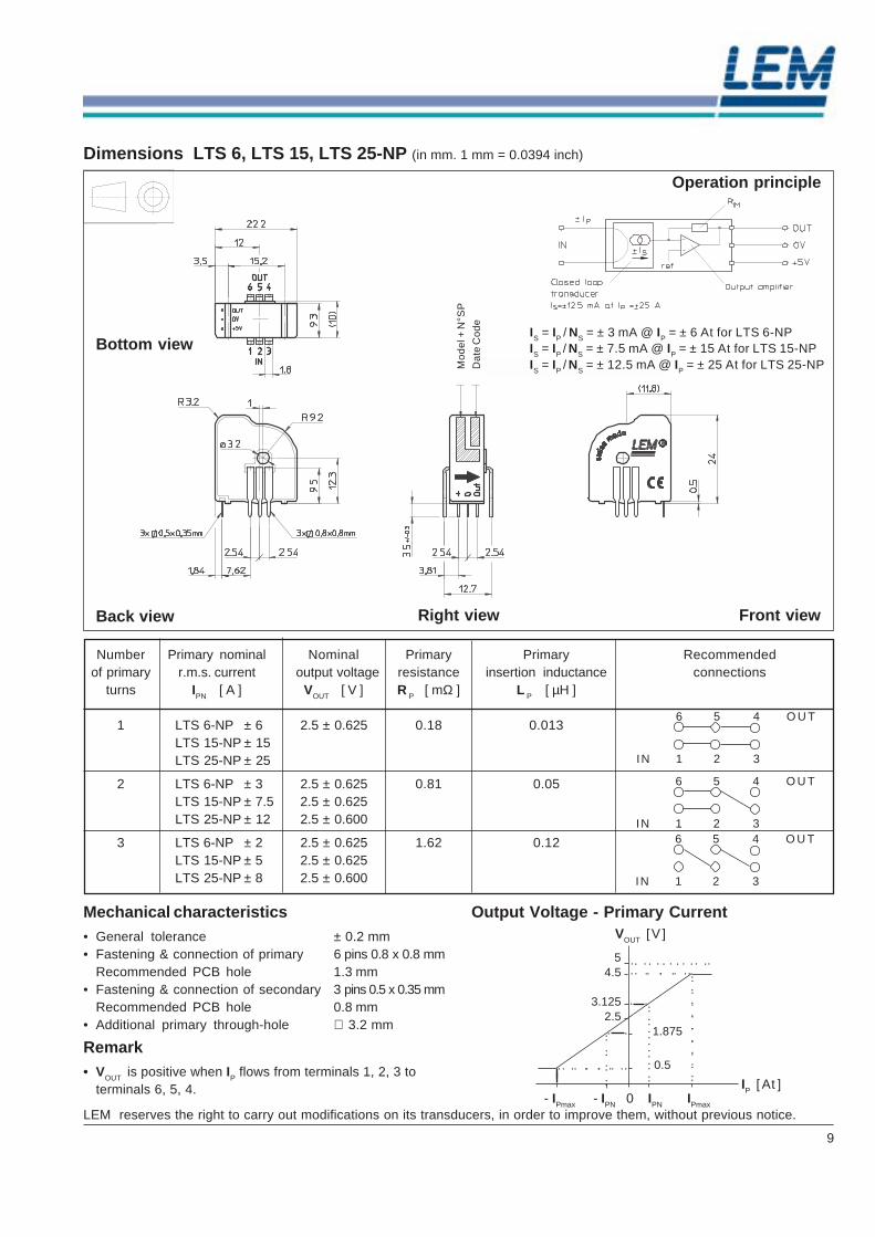
Output Voltage - Primary CurrentMechanical characteristics• General tolerance ± 0.2 mm• Fastening & connection of primary 6 pins 0.8 x 0.8 mm
Recommended PCB hole 1.3 mm• Fastening & connection of secondary 3 pins 0.5 x 0.35 mm
Recommended PCB hole 0.8 mm• Additional primary through-hole ∅ 3.2 mm
Remark• VOUT is positive when IP flows from terminals 1, 2, 3 to
terminals 6, 5, 4.
Right viewBack view Front view
Dimensions LTS 6, LTS 15, LTS 25-NP (in mm. 1 mm = 0.0394 inch)
Number Primary nominal Nominal Primary Primary Recommendedof primary r.m.s. current output voltage resistance insertion inductance connections
turns IPN [ A ] VOUT [ V ] R P [ mΩ ] L P [ µH ]
1 LTS 6-NP ± 6 2.5 ± 0.625 0.18 0.013LTS 15-NP ± 15LTS 25-NP ± 25
2 LTS 6-NP ± 3 2.5 ± 0.625 0.81 0.05LTS 15-NP ± 7.5 2.5 ± 0.625LTS 25-NP ± 12 2.5 ± 0.600
3 LTS 6-NP ± 2 2.5 ± 0.625 1.62 0.12LTS 15-NP ± 5 2.5 ± 0.625LTS 25-NP ± 8 2.5 ± 0.600
6 5 4 O U T
IN 1 2 3
6 5 4 O U T
IN 1 2 36 5 4 O U T
IN 1 2 3
- IPmax - IPN 0 IPN IPmax
54.5
3.1252.5
1.875
0.5
IP [ At ]
VOUT [ V ]
LEM reserves the right to carry out modifications on its transducers, in order to improve them, without previous notice.
IS = IP / NS = ± 3 mA @ IP = ± 6 At for LTS 6-NPIS = IP / NS = ± 7.5 mA @ IP = ± 15 At for LTS 15-NPIS = IP / NS = ± 12.5 mA @ IP = ± 25 At for LTS 25-NP
Bottom view
Operation principle
Mo
de
l + N
°SP
Dat
e C
ode

10
Notes
As far as patents or other rights of third parties areconcerned, liability is only assumed for components per se,not for applications, processes and circuits implemented withcomponents or assemblies. For more details see theavailable data sheets.Terms of delivery and rights to change design or specifica-tions are reserved.
Technical Information "ASIC Based Closed-LoopTransducers from 6 A up to 25 A nominal"
Published by LEM Components LEM Geneva, Switzerland 2003, e-mail: [email protected]
All Rights reservedThe paper of this publication is produced with pulp bleachedwithout chlorine, neutral sized and non-aging.
11
5 Years Warrantyon LEM Transducers
LEM designs and manufactures high quality andhigh reliability products for its customers over the entire world.
Since 1972, we have delivered several million current and voltage transducers which are,for most of them, still in operation on traction vehicles, industrial motor drives,
UPS systems and many other applications requiring high quality standards.
Our 5 years warranty applies on all LEM transducers delivered fromthe 1st. of January 1996 and is valid in addition to the legal warranty.
The warranty granted on our Transducers is for a periodof 5 years (60 months) from the date of their delivery.
During this period we shall replace or repair at our cost all defective parts(provided the defect is due to defective material or workmanship).
Further claims as well as claims for the compensation of damages, which donot occur on the delivered material itself, are not covered by this warranty.
All defects must be notified to us immediately and faulty material must be returnedto the factory along with a description of the defect.
Warranty repairs and or replacements are carried out at our discretion.The customer bears the transport costs. An extension of the warranty period following
repairs undertaken under warranty cannot be granted.
The warranty will be invalidated if the buyer has modified or repaired, or has had repairedby a third party the material without LEM's written consent.
The warranty does not cover any damage caused byincorrect conditions of use and cases of force majeure.
No responsibility will apply except legal requirements regarding product liability.
The warranty explicitly excludes all claims exceeding the above conditions.
LEM, Geneva, January 1. 2001Business Area Components
Paul Van IseghemPresident of LEM Components
LEM Components8, Chemin des Aulx, CH-1228 Plan-les-OuatesTel. +41/22/7 06 11 11, Fax +41/22/7 94 94 78e-mail: [email protected]; http://www.lem.com
Distributor
Publication CH 99105a E/US (02.03 • 5.5 • CDH)
BAC/E, 02.03
LEM International Sales NetworkLEM International Sales NetworkLEM International Sales NetworkLEM International Sales NetworkLEM International Sales NetworkAustriaAustriaAustriaAustriaAustriaLEM NORMA GmbHLEM NORMA GmbHLEM NORMA GmbHLEM NORMA GmbHLEM NORMA GmbHLiebermannstraße F 01Liebermannstraße F 01Liebermannstraße F 01Liebermannstraße F 01Liebermannstraße F 01A-2345 Brunn am GebirgeA-2345 Brunn am GebirgeA-2345 Brunn am GebirgeA-2345 Brunn am GebirgeA-2345 Brunn am GebirgeTel.Tel.Tel.Tel.Tel. 02236/69 15 0202236/69 15 0202236/69 15 0202236/69 15 0202236/69 15 02FaxFaxFaxFaxFax 02236/69 14 0002236/69 14 0002236/69 14 0002236/69 14 0002236/69 14 00e-mail: [email protected]: [email protected]: [email protected]: [email protected]: [email protected]
BeNeLuxBeNeLuxBeNeLuxBeNeLuxBeNeLuxLEM Belgium sprl-bvba,LEM Belgium sprl-bvba,LEM Belgium sprl-bvba,LEM Belgium sprl-bvba,LEM Belgium sprl-bvba,Route de Petit-Roeulx, 95Route de Petit-Roeulx, 95Route de Petit-Roeulx, 95Route de Petit-Roeulx, 95Route de Petit-Roeulx, 95B-7090 Braine-le-ComteB-7090 Braine-le-ComteB-7090 Braine-le-ComteB-7090 Braine-le-ComteB-7090 Braine-le-ComteTel.Tel.Tel.Tel.Tel. +32 67 55 01 14+32 67 55 01 14+32 67 55 01 14+32 67 55 01 14+32 67 55 01 14FaxFaxFaxFaxFax +32 67 55 01 15+32 67 55 01 15+32 67 55 01 15+32 67 55 01 15+32 67 55 01 15e-mail: [email protected]: [email protected]: [email protected]: [email protected]: [email protected]
CroatiaCroatiaCroatiaCroatiaCroatiaProteus ElectricVia di Noghere 94/1I-34147 Muggia-AquiliniaTel. +39/40/232 188Fax +39/40/232 440e-mail: [email protected]
Czech RepublicCzech RepublicCzech RepublicCzech RepublicCzech RepublicPE & ED Spol. S.R.O.Koblovska 101/23CZ-71100 Ostrava/KoblovTel. 069/6239 256Fax. 069/6239 531email: [email protected]
DenmarkDenmarkDenmarkDenmarkDenmarkDeltron-Conelec A/SBanemarksvej 50 B2605 BroendbyTel. 45/43 43 43 42Fax 45/43 29 37 00e-mail: [email protected]
FinlandFinlandFinlandFinlandFinlandEtra-Dielectric OyLampputie 2SF-00740 Helsinki 74Tel. 09/3699 366Fax 09/3699 311e-mail: [email protected]
FranceFranceFranceFranceFranceLEM France Sarl,LEM France Sarl,LEM France Sarl,LEM France Sarl,LEM France Sarl,La Ferme de CourtaboeufLa Ferme de CourtaboeufLa Ferme de CourtaboeufLa Ferme de CourtaboeufLa Ferme de Courtaboeuf19 avenue des Indes19 avenue des Indes19 avenue des Indes19 avenue des Indes19 avenue des IndesF-91969 Courtaboeuf CedexF-91969 Courtaboeuf CedexF-91969 Courtaboeuf CedexF-91969 Courtaboeuf CedexF-91969 Courtaboeuf CedexTel.Tel.Tel.Tel.Tel. 01/69 18 17 5001/69 18 17 5001/69 18 17 5001/69 18 17 5001/69 18 17 50FaxFaxFaxFaxFax 01/69 28 24 2901/69 28 24 2901/69 28 24 2901/69 28 24 2901/69 28 24 29e-mail: [email protected]: [email protected]: [email protected]: [email protected]: [email protected]
GermanyGermanyGermanyGermanyGermanyLEM Deutschland GmbHLEM Deutschland GmbHLEM Deutschland GmbHLEM Deutschland GmbHLEM Deutschland GmbHFrankfurter Straße 74Frankfurter Straße 74Frankfurter Straße 74Frankfurter Straße 74Frankfurter Straße 74D-64521 Groß-GerauD-64521 Groß-GerauD-64521 Groß-GerauD-64521 Groß-GerauD-64521 Groß-GerauTel.Tel.Tel.Tel.Tel. 06152/9301-006152/9301-006152/9301-006152/9301-006152/9301-0FaxFaxFaxFaxFax 06152/846 6106152/846 6106152/846 6106152/846 6106152/846 61e-mail: [email protected]: [email protected]: [email protected]: [email protected]: [email protected]
HungaryHungaryHungaryHungaryHungaryOrszaczky Trading Co. LtdKorányi Sandor U. 28H-1089 BudapestTel. 1/314 42 25Fax. 1/314 42 25email: [email protected]
ItalyItalyItalyItalyItalyLEM Italia SrlLEM Italia SrlLEM Italia SrlLEM Italia SrlLEM Italia Srlvia V.Bellini, 7via V.Bellini, 7via V.Bellini, 7via V.Bellini, 7via V.Bellini, 7I-35030 Selvazzano Dentro, PDI-35030 Selvazzano Dentro, PDI-35030 Selvazzano Dentro, PDI-35030 Selvazzano Dentro, PDI-35030 Selvazzano Dentro, PDTel.Tel.Tel.Tel.Tel. 049/805 60 60049/805 60 60049/805 60 60049/805 60 60049/805 60 60FaxFaxFaxFaxFax 049/805 60 59049/805 60 59049/805 60 59049/805 60 59049/805 60 59e-mail: [email protected]: [email protected]: [email protected]: [email protected]: [email protected]
IsraelIsraelIsraelIsraelIsraelOfer Levin Technological ApplicationPO Box 18247IL-Tel Aviv 611 81Tel. 03/55 862 79Fax 03/55 862 82e-mail: [email protected]
NorwayNorwayNorwayNorwayNorwayHolst & Fleischer A/SBox 5404 MajorstuenN-0305 OsloTel. 22 06 63 50Fax 22 06 63 51e-mail: [email protected]
PolandPolandPolandPolandPolandDACPOL Co., Ltd.Teren Zakladu LaminaUl. Pulawska 34PL-05-500 PiasecznoTel. 022/757 07 13Fax 022/757 07 64e-mail: [email protected]
PortugalPortugalPortugalPortugalPortugalMaquindus Engenharia eserviços, LdaRua da Ponte, 5P-4435 Rio TintoTel. 01/24 85 02 80/1Fax 01/24 85 02 90e-mail: [email protected]
RumaniaRumaniaRumaniaRumaniaRumaniaSYSCOM-18 S.r.l.Calea Plevnei 139, sector 6R-77131 BucarestTel. 1/222 91 76Fax 1/222 91 76e-mail: [email protected]
RussiaRussiaRussiaRussiaRussiaTVLEMTVLEMTVLEMTVLEMTVLEMMarshall Budionny Str.Marshall Budionny Str.Marshall Budionny Str.Marshall Budionny Str.Marshall Budionny Str.170023 TVER170023 TVER170023 TVER170023 TVER170023 TVERTel.Tel.Tel.Tel.Tel. 0822/44 40 530822/44 40 530822/44 40 530822/44 40 530822/44 40 53FaxFaxFaxFaxFax 0822/44 40 530822/44 40 530822/44 40 530822/44 40 530822/44 40 53e-mail: [email protected]: [email protected]: [email protected]: [email protected]: [email protected]
SloveniaSloveniaSloveniaSloveniaSloveniaProteus ElectricVia di Noghere 94/1I-34147 Muggia-AquiliniaTel. +39/40/23 21 88Fax +39/40/23 24 40e-mail: [email protected]
SpainSpainSpainSpainSpainSUMELECDoris de Schade S.L.Avd. Sancho Rosa 66E-28708 San Sebastian de los ReyesTel. 91/623 68 28Fax 91/623 67 02e-mail:[email protected]
SwedenSwedenSwedenSwedenSwedenBeving Elektronik A.B.Jägerhorns väg 8S-14105 HuddingeTel. 08/680 11 99Fax 08/680 11 88e-mail:[email protected]
SwitzerlandSwitzerlandSwitzerlandSwitzerlandSwitzerlandSIMPEX Electronic AGBinzackerstrasse, 33CH-8622 WetzikonTel. 01/931 10 10Fax 01/931 10 11e-mail: [email protected]
SwitzerlandSwitzerlandSwitzerlandSwitzerlandSwitzerlandLEM SALEM SALEM SALEM SALEM SA8, Chemin des Aulx8, Chemin des Aulx8, Chemin des Aulx8, Chemin des Aulx8, Chemin des AulxCH-1228 Plan-les-OuatesCH-1228 Plan-les-OuatesCH-1228 Plan-les-OuatesCH-1228 Plan-les-OuatesCH-1228 Plan-les-OuatesTel.Tel.Tel.Tel.Tel. 022/706 11 11022/706 11 11022/706 11 11022/706 11 11022/706 11 11FaxFaxFaxFaxFax 022/794 94 78022/794 94 78022/794 94 78022/794 94 78022/794 94 78e-mail:[email protected]:[email protected]:[email protected]:[email protected]:[email protected]
TurkeyTurkeyTurkeyTurkeyTurkeyÖzdisan Electronik PazarlamaGalata Kulesi Sokak N°34TR-80020 Kuledibi/IstanbulTel. 0212/252 0884Fax 0212/244 59 43e-mail: [email protected]
United Kingdom and EireUnited Kingdom and EireUnited Kingdom and EireUnited Kingdom and EireUnited Kingdom and EireLEM U.K.LtdLEM U.K.LtdLEM U.K.LtdLEM U.K.LtdLEM U.K.LtdGeneva Court, 1Geneva Court, 1Geneva Court, 1Geneva Court, 1Geneva Court, 1Penketh Place, West Pimbo,Penketh Place, West Pimbo,Penketh Place, West Pimbo,Penketh Place, West Pimbo,Penketh Place, West Pimbo,SkelmersdaleSkelmersdaleSkelmersdaleSkelmersdaleSkelmersdaleLancashire WN8 9QXLancashire WN8 9QXLancashire WN8 9QXLancashire WN8 9QXLancashire WN8 9QXTel.Tel.Tel.Tel.Tel. 01695/72 07 7701695/72 07 7701695/72 07 7701695/72 07 7701695/72 07 77FaxFaxFaxFaxFax 01695/507 0401695/507 0401695/507 0401695/507 0401695/507 04e-mail: [email protected]: [email protected]: [email protected]: [email protected]: [email protected]
BrazilBrazilBrazilBrazilBrazilIntech Engenharia Ltda5 Andar CJ 52Av. Adolfo Pinheiro, 1010BR-04734-002 Sao PauloTel. 011/554 814 33Fax 011/554 814 33e-mail:[email protected]
CanadaCanadaCanadaCanadaCanadaAlliance Components Inc.270 Warden AvenueCAN-Scarborough, ON M1N 3A1Tel. 416-690-78 10Fax 416-690-78 11
ChileChileChileChileChileELECTROCHILEFreire 979 of. 303-304QuilpueTel. 032/92 32 22Fax 032/92 32 22e-mail: [email protected]
South AfricaSouth AfricaSouth AfricaSouth AfricaSouth AfricaDenver Technical Products Ltd.P.O. Box 75810SA-2047 Garden ViewTel. 011/626 20 23Fax 011/626 20 09e-mail: [email protected]
USAUSAUSAUSAUSALEM U.S.A., Inc.LEM U.S.A., Inc.LEM U.S.A., Inc.LEM U.S.A., Inc.LEM U.S.A., Inc.6643 West Mill Road6643 West Mill Road6643 West Mill Road6643 West Mill Road6643 West Mill RoadUSA Milwaukee, Wi 53218USA Milwaukee, Wi 53218USA Milwaukee, Wi 53218USA Milwaukee, Wi 53218USA Milwaukee, Wi 53218Tel.Tel.Tel.Tel.Tel. 414/ 353 07 11 or414/ 353 07 11 or414/ 353 07 11 or414/ 353 07 11 or414/ 353 07 11 or
800/236 53 66800/236 53 66800/236 53 66800/236 53 66800/236 53 66FaxFaxFaxFaxFax 414/353 07 33414/353 07 33414/353 07 33414/353 07 33414/353 07 33e-mail: [email protected]: [email protected]: [email protected]: [email protected]: [email protected]
USAUSAUSAUSAUSALEM U.S.A., Inc.LEM U.S.A., Inc.LEM U.S.A., Inc.LEM U.S.A., Inc.LEM U.S.A., Inc.27 Rt 191A27 Rt 191A27 Rt 191A27 Rt 191A27 Rt 191APO Box 1207PO Box 1207PO Box 1207PO Box 1207PO Box 1207USA-Amherst, NH 03031USA-Amherst, NH 03031USA-Amherst, NH 03031USA-Amherst, NH 03031USA-Amherst, NH 03031Tel.Tel.Tel.Tel.Tel. 603/672 71 57603/672 71 57603/672 71 57603/672 71 57603/672 71 57FaxFaxFaxFaxFax 603/672 71 59603/672 71 59603/672 71 59603/672 71 59603/672 71 59e-mail: [email protected]: [email protected]: [email protected]: [email protected]: [email protected]
AustraliaAustraliaAustraliaAustraliaAustraliaFastron Technologies Pty Ltd.25 Kingsley CloseRowvilleRowvilleRowvilleRowvilleRowvilleMelbourneVictoria 3178Tel. 61-(0)3 9763 5155Fax. 61-(0)3 9763 5166e-mail: [email protected]
USAUSAUSAUSAUSALEM U.S.A., Inc.LEM U.S.A., Inc.LEM U.S.A., Inc.LEM U.S.A., Inc.LEM U.S.A., Inc.7985 Vance Drive7985 Vance Drive7985 Vance Drive7985 Vance Drive7985 Vance DriveUSA Arvada, CO 80003USA Arvada, CO 80003USA Arvada, CO 80003USA Arvada, CO 80003USA Arvada, CO 80003Tel.Tel.Tel.Tel.Tel. 303/403 17 69303/403 17 69303/403 17 69303/403 17 69303/403 17 69FaxFaxFaxFaxFax 303/403 15 89303/403 15 89303/403 15 89303/403 15 89303/403 15 89e-mail: [email protected]: [email protected]: [email protected]: [email protected]: [email protected]
ChinaChinaChinaChinaChinaBeijing LEM Electronics Co. LtdBeijing LEM Electronics Co. LtdBeijing LEM Electronics Co. LtdBeijing LEM Electronics Co. LtdBeijing LEM Electronics Co. LtdNo. 1 Standard FactoryNo. 1 Standard FactoryNo. 1 Standard FactoryNo. 1 Standard FactoryNo. 1 Standard FactoryBuilding BBuilding BBuilding BBuilding BBuilding BAirport Industria AreaAirport Industria AreaAirport Industria AreaAirport Industria AreaAirport Industria AreaCN-Beijing 101300CN-Beijing 101300CN-Beijing 101300CN-Beijing 101300CN-Beijing 101300Tel.Tel.Tel.Tel.Tel. 10/80 49 04 7010/80 49 04 7010/80 49 04 7010/80 49 04 7010/80 49 04 70FaxFaxFaxFaxFax 10/80 49 04 7310/80 49 04 7310/80 49 04 7310/80 49 04 7310/80 49 04 73e-mail: [email protected]: [email protected]: [email protected]: [email protected]: [email protected]
IndiaIndiaIndiaIndiaIndiaGlobetek122/49, 27th Cross7th Block, JayanagarIN-Bangalore-560082Tel. 80/663 57 76Fax 80/658 1556e-mail: [email protected]
JapanJapanJapanJapanJapanNANALEM K.K.NANALEM K.K.NANALEM K.K.NANALEM K.K.NANALEM K.K.1-27-14 Morino, Machida1-27-14 Morino, Machida1-27-14 Morino, Machida1-27-14 Morino, Machida1-27-14 Morino, MachidaJ-194-0022 TokyoJ-194-0022 TokyoJ-194-0022 TokyoJ-194-0022 TokyoJ-194-0022 TokyoTel.Tel.Tel.Tel.Tel. 042/725 8151042/725 8151042/725 8151042/725 8151042/725 8151FaxFaxFaxFaxFax 042/728 8119042/728 8119042/728 8119042/728 8119042/728 8119e-mail: [email protected]: [email protected]: [email protected]: [email protected]: [email protected]
KoreaKoreaKoreaKoreaKoreaYoungwoo Ind. Co.P.O.Box 10265K-SeoulTel. 02/5 93 8146Fax 02/5 35 04 41e-mail:[email protected]
SingaporeSingaporeSingaporeSingaporeSingaporeOverseas Trade Center Ltd.03 - 168 Bukit Merah L.1BLK 125/Alexandra Vil.RS-150125 SingaporeTel. 272 60 77Fax 278 21 34e-mail:[email protected]
TaiwanTaiwanTaiwanTaiwanTaiwanTope Co., Ltd.P.O. Box 101-3563F, No. 344, Fu Shing RoadROC-10483 TaipeiTel. 02/509 54 80Fax 02/504 31 61e-mail: [email protected]
Eur
ope
• M
idd
le E
ast
Eur
ope
• M
idd
le E
ast
Eur
ope
• M
idd
le E
ast
Eur
ope
• M
idd
le E
ast
Eur
ope
• M
idd
le E
ast
Afr
ica
• A
mer
ica
Afr
ica
• A
mer
ica
Afr
ica
• A
mer
ica
Afr
ica
• A
mer
ica
Afr
ica
• A
mer
ica
A
sia
• P
acifi
c
Asi
a •
Pac
ific
A
sia
• P
acifi
c
Asi
a •
Pac
ific
A
sia
• P
acifi
c
TaiwanTaiwanTaiwanTaiwanTaiwanLECTRON Co., Ltd.9F, NO 171, SEC.2,Tatung. RD. Hsichih CityTaipei Hsien 221Taiwan, R.O.CTel. 886 2 8692 6023Fax. 886 2 8692 6098e-mail: [email protected]