Embed Size (px)
Citation preview
PRINTED IN U.S.A.
USER'S HANDBOOK ELECTRONIC BELL (A80301) JANUARY 2005 (REVISED JUNE 2014)
DOCUMENT NO. SIG-00-04-09 VERSION A.2
Siemens Industry, Inc., Rail Automation 9568 Archibald Ave., Suite 100, Rancho Cucamonga, California 91730
1-800-793-7233 Copyright © 2014 Siemens Industry, Inc., Rail Automation All rights reserved
ELECTRONIC BELL USER’S HANDBOOK
ii Document No.: SIG-00-04-09 January 2005 (Revised June 2014) Version: A.2
PROPRIETARY INFORMATION Siemens Industry, Inc., Rail Automation (Siemens) has a proprietary interest in the information contained herein and, in some instances, has patent rights in the systems and components described. It is requested that you distribute this information only to those responsible people within your organization who have an official interest. This document, or the information disclosed herein, shall not be reproduced or transferred to other documents or used or disclosed for manufacturing or for any other purpose except as specifically authorized in writing by Siemens.
TRANSLATIONS
The manuals and product information of Siemens are intended to be produced and read in English. Any translation of the manuals and product information are unofficial and can be imprecise and inaccurate in whole or in part. Siemens does not warrant the accuracy, reliability, or timeliness of any information contained in any translation of manual or product information from its original official released version in English and shall not be liable for any losses caused by such reliance on the accuracy, reliability, or timeliness of such information. Any person or entity who relies on translated information does so at his or her own risk.
WARRANTY INFORMATION
Siemens Industry, Inc., Rail Automation warranty policy is as stated in the current Terms and Conditions of Sale document. Warranty adjustments will not be allowed for products or components which have been subjected to abuse, alteration, improper handling or installation, or which have not been operated in accordance with Seller's instructions. Alteration or removal of any serial number or identification mark voids the warranty.
SALES AND SERVICE LOCATIONS
Technical assistance and sales information on Siemens Industry, Inc., Rail Automation products may be obtained at the following locations:
Siemens Industry, Inc., Rail Automation Siemens Industry, Inc., Rail Automation 2400 NELSON MILLER PARKWAY 939 S. MAIN STREET LOUISVILLE, KENTUCKY 40223 MARION, KENTUCKY 42064 TELEPHONE: (502) 618-8800 TELEPHONE: (270) 918-7800 FAX: (502) 618-8810 CUSTOMER SERVICE: (800) 626-2710 SALES & SERVICE: (800) 626-2710 TECHNICAL SUPPORT: (800) 793-7233 WEB SITE: http://www.rail-automation.com/ FAX: (270) 918-7830
Microsoft®, Windows®, and Windows NT 4.0®, are registered trademarks of the Microsoft Corporation. Windows 95™, and Windows 2000™ are trademarks of the Microsoft Corporation. WAGO® is a registered trademark of the Wago Corporation. Echelon® and LonTalk® are registered trademarks of the Echelon Corporation. All other trademarks belong to their respective owners.
ELECTRONIC BELL USER’S HANDBOOK
iii Document No.: SIG-00-04-09 January 2005 (Revised June 2014) Version: A.2
DOCUMENT HISTORY Version Release
Date Sections Changed
Details of Change
A Januarry 2005
Initial release
A.1 October 2005
1 Page 1-2:
• Deleted “average power consumption 6 watts” from Voltage - Electronic Specifications paragraph.
Page 1-3:
• Added Power Consumption specification information to Electronic Specifications paragraph.
A.2 June 2014 all Rebrand for Siemens
ELECTRONIC BELL USER’S HANDBOOK
iv Document No.: SIG-00-04-09 January 2005 (Revised June 2014) Version: A.2
NOTES, CAUTIONS, AND WARNINGS Throughout this manual, notes, cautions, and warnings are frequently used to direct the reader’s attention to specific information. Use of the three terms is defined as follows:
WARNING
INDICATES A POTENTIALLY HAZARDOUS SITUATION WHICH, IF NOT AVOIDED, COULD RESULT IN DEATH OR SERIOUS INJURY. WARNINGS ALWAYS TAKE PRECEDENCE OVER NOTES, CAUTIONS, AND ALL OTHER INFORMATION.
CAUTION
REFERS TO PROPER PROCEDURES OR PRACTICES WHICH IF NOT STRICTLY OBSERVED, COULD RESULT IN A POTENTIALLY HAZARDOUS SITUATION AND/OR POSSIBLE DAMAGE TO EQUIPMENT. CAUTIONS TAKE PRECEDENCE OVER NOTES AND ALL OTHER INFORMATION, EXCEPT WARNINGS.
NOTE
Generally used to highlight certain information relating to the topic under discussion.
If there are any questions, contact Siemens Industry Inc., Rail Automation Application Engineering.
ELECTRONIC BELL USER’S HANDBOOK
v Document No.: SIG-00-04-09 January 2005 (Revised June 2014) Version: A.2
TABLE OF CONTENTS
Section Title Page PROPRIETARY INFORMATION ......................................................................... ii TRANSLATIONS ................................................................................................. ii WARRANTY INFORMATION............................................................................... ii SALES AND SERVICE LOCATIONS ................................................................... ii DOCUMENT HISTORY ...................................................................................... iii NOTES, CAUTIONS, AND WARNINGS ............................................................. iv
1.0 Overview .......................................................................................................... 1-1
1.1 Introduction ...................................................................................................... 1-1
1.2 Specifications ................................................................................................... 1-2
1.2.1 Physical Specifications..................................................................................... 1-2 1.2.2 Electronic Specifications .................................................................................. 1-2 1.2.3 Environmental Specifications ........................................................................... 1-3 1.2.4 Wiring Specifications ........................................................................................ 1-3
2.0 Installing the Electronic Bell ............................................................................. 2-1
2.1 Introduction ...................................................................................................... 2-1
2.2 Attaching the Bell Wires ................................................................................... 2-1
2.3 Attaching the Electronic Bell to the Pole ........................................................... 2-1
2.4 Testing the Installation ..................................................................................... 2-2
3.0 Troubleshooting ............................................................................................... 3-1
3.1 Introduction ...................................................................................................... 3-1
3.2 Finding and Fixing Problems ............................................................................ 3-1
3.3 Ordering Information ........................................................................................ 3-1

ELECTRONIC BELL USER’S HANDBOOK
vi Document No.: SIG-00-04-09 January 2005 (Revised June 2014) Version: A.2
This page intentionally left blank
ELECTRONIC BELL USER’S HANDBOOK
1-1 Document No.: SIG-00-04-09 January 2005 (Revised June 2014) Version: A.2
1.0 OVERVIEW
1.1 INTRODUCTION
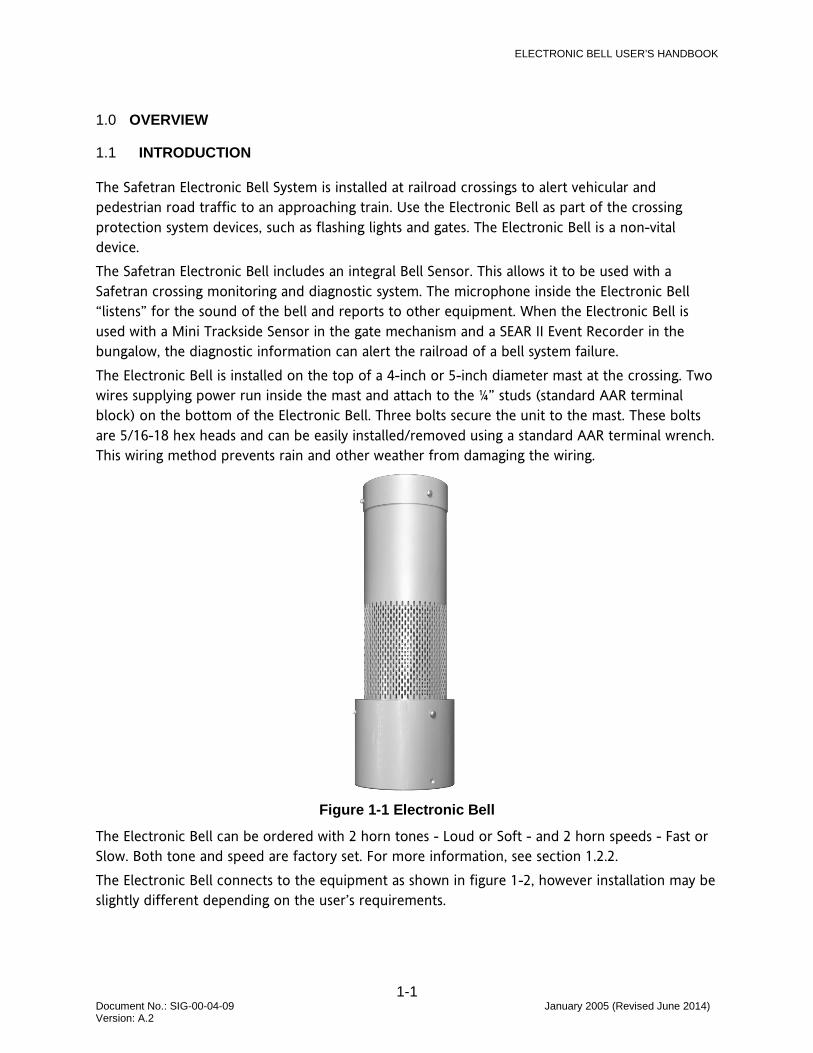
The Safetran Electronic Bell System is installed at railroad crossings to alert vehicular and pedestrian road traffic to an approaching train. Use the Electronic Bell as part of the crossing protection system devices, such as flashing lights and gates. The Electronic Bell is a non-vital device. The Safetran Electronic Bell includes an integral Bell Sensor. This allows it to be used with a Safetran crossing monitoring and diagnostic system. The microphone inside the Electronic Bell “listens” for the sound of the bell and reports to other equipment. When the Electronic Bell is used with a Mini Trackside Sensor in the gate mechanism and a SEAR II Event Recorder in the bungalow, the diagnostic information can alert the railroad of a bell system failure. The Electronic Bell is installed on the top of a 4-inch or 5-inch diameter mast at the crossing. Two wires supplying power run inside the mast and attach to the ¼” studs (standard AAR terminal block) on the bottom of the Electronic Bell. Three bolts secure the unit to the mast. These bolts are 5/16-18 hex heads and can be easily installed/removed using a standard AAR terminal wrench. This wiring method prevents rain and other weather from damaging the wiring.
Figure 1-1 Electronic Bell
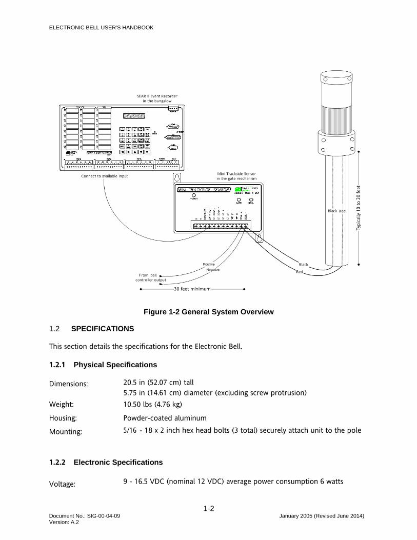
The Electronic Bell can be ordered with 2 horn tones - Loud or Soft - and 2 horn speeds - Fast or Slow. Both tone and speed are factory set. For more information, see section 1.2.2. The Electronic Bell connects to the equipment as shown in figure 1-2, however installation may be slightly different depending on the user’s requirements.
ELECTRONIC BELL USER’S HANDBOOK
1-2 Document No.: SIG-00-04-09 January 2005 (Revised June 2014) Version: A.2
Figure 1-2 General System Overview
1.2 SPECIFICATIONS
This section details the specifications for the Electronic Bell.
1.2.1 Physical Specifications
Dimensions: 20.5 in (52.07 cm) tall 5.75 in (14.61 cm) diameter (excluding screw protrusion)
Weight: 10.50 lbs (4.76 kg)
Housing: Powder-coated aluminum
Mounting: 5/16 - 18 x 2 inch hex head bolts (3 total) securely attach unit to the pole
1.2.2 Electronic Specifications
Voltage: 9 - 16.5 VDC (nominal 12 VDC) average power consumption 6 watts
ELECTRONIC BELL USER’S HANDBOOK
1-3 Document No.: SIG-00-04-09 January 2005 (Revised June 2014) Version: A.2
Power Consumption:
0.5A (0.9A peak) @ 13.2V 0.6A (1.0A peak) @ 9V 0.5A (0.9A peak) @ 16.5V
Horn: 15 watts, 8 ohm, weather-proof
Sound: 2 tones:
• Loud: Approx 94 db • Soft: Approx 82 db
2 repetition rates:
• Fast: Approx 200 pulses per minute
• Slow: Approx 160 pulses per minute
Bell Sensor: Interfaces with a Safetran MTSS unit, part number A80285.
Microphone: Omni-directional, weatherproof, shock/vibration resistant.
1.2.3 Environmental Specifications
Temperature: -40 °F to +158 °F (-40 °C to +70 °C)
Humidity: 0 – 95% non-condensing
1.2.4 Wiring Specifications
Terminate wires with standard ¼” ring terminals.

ELECTRONIC BELL USER’S HANDBOOK
1-4 Document No.: SIG-00-04-09 January 2005 (Revised June 2014) Version: A.2
This page intentionally left blank
ELECTRONIC BELL USER’S HANDBOOK
2-1 Document No.: SIG-00-04-09 January 2005 (Revised June 2014) Version: A.2
2.0 INSTALLING THE ELECTRONIC BELL
2.1 INTRODUCTION
This section explains how to install the Electronic Bell on a 4- or 5-inch (outside diameter) pole. Following installation, the Electronic Bell should be tested.
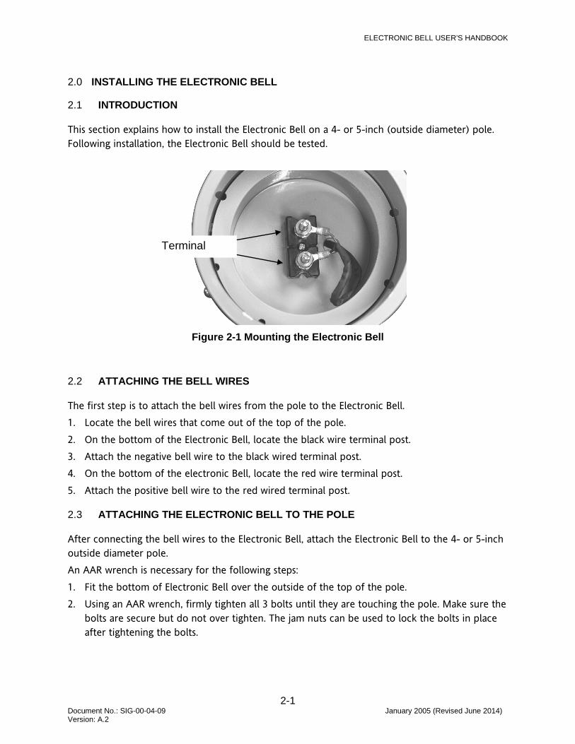
Figure 2-1 Mounting the Electronic Bell
2.2 ATTACHING THE BELL WIRES
The first step is to attach the bell wires from the pole to the Electronic Bell. 1. Locate the bell wires that come out of the top of the pole. 2. On the bottom of the Electronic Bell, locate the black wire terminal post. 3. Attach the negative bell wire to the black wired terminal post. 4. On the bottom of the electronic Bell, locate the red wire terminal post. 5. Attach the positive bell wire to the red wired terminal post.
2.3 ATTACHING THE ELECTRONIC BELL TO THE POLE
After connecting the bell wires to the Electronic Bell, attach the Electronic Bell to the 4- or 5-inch outside diameter pole. An AAR wrench is necessary for the following steps: 1. Fit the bottom of Electronic Bell over the outside of the top of the pole. 2. Using an AAR wrench, firmly tighten all 3 bolts until they are touching the pole. Make sure the
bolts are secure but do not over tighten. The jam nuts can be used to lock the bolts in place after tightening the bolts.
Terminal
ELECTRONIC BELL USER’S HANDBOOK
2-2 Document No.: SIG-00-04-09 January 2005 (Revised June 2014) Version: A.2
2.4 TESTING THE INSTALLATION
Following installation, test the Electronic Bell as follows: Testing consists of two parts: • Making the Electronic Bell sound • Checking the Bell light on the Mini Trackside Sensor (MTSS) 1. Energize the bell output on the controller and verify that the Electronic Bell sounds. 2. If MTSS is used, verify that when the Electronic Bell sounds, the Bell light on the MTSS is lit.
This indicates that the Electronic Bell audio circuit is picking up the bell sound and providing an indication to the MTSS.
ELECTRONIC BELL USER’S HANDBOOK
3-1 Document No.: SIG-00-04-09 January 2005 (Revised June 2014) Version: A.2
3.0 TROUBLESHOOTING
3.1 INTRODUCTION
The Electronic Bell is designed to function without a problem. However, because it connects to other equipment, some troubleshooting may be required.
3.2 FINDING AND FIXING PROBLEMS
Make sure the bell controller output is present, then check the following:
Symptom Problem Solution
No sound from bell Bad wiring or contact Check for power at the bell terminal block
Horn Speaker malfunction Replace unit
Drive circuit malfunction Replace unit
MTSS bell light is off Bad wiring or contact Check for proper contact at MTSS connector
Microphone malfunction Replace unit
Detection circuit malfunction Replace unit
3.3 ORDERING INFORMATION
The following table displays the different bell sounds that can be configured from the factory. Use the chart below to select the one to order.
For this sound Order this product number
Loud, Fast 8000-80301-0001
Loud, Slow 8000-80301-0002
Soft, Fast 8000-80301-0003
Soft, Slow 8000-80301-0004

Siemens Industry, Inc., Rail Automation 2400 Nelson Miller Parkway Louisville, Kentucky 40223
(502) 618-8800
Siemens Industry, Inc., Rail Automation California R&D Division
9568 Archibald Ave., Suite 100 Rancho Cucamonga, California 91730
(909) 532-5300