Embed Size (px)
Citation preview
Electron Microscopy Laboratory
Introduction to transmission electron microscopyTutor: Peter Harris
The aims of this course are:
● to describe the components of the transmission electron microscope (TEM)
● to explain the origin of contrast in TEM images
● to outline some of the techniques used for specimen preparation
● to describe the effects of astigmatism and aberrations in TEM
Click on the buttons to move between slides.
(Make sure you are in “Slide Show” mode)
Electron Microscopy Laboratory
Introduction to transmission electron microscopy
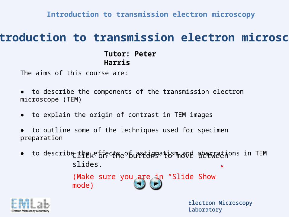
Transmission electron microscopy (TEM) is a technique for achieving high resolution images of thin specimens. A beam of high energy electrons passes through the specimen and is then focussed to form an image.
The resolution of the TEM is greater than that of the scanning electron microscope, and is typically of the order of 0.2 nm. This compares with approximately 2 nm for the SEM and around 0.2 m for the conventional optical microscope.
Imaging in the TEM must be carried out under vacuum, as electrons cannot travel through air. The basic components of the TEM are illustrated on the next slide.
Units:
1 nm = 10-9 m; 1 m = 10-6 m
Overview
Electron Microscopy Laboratory
Introduction to transmission electron microscopy
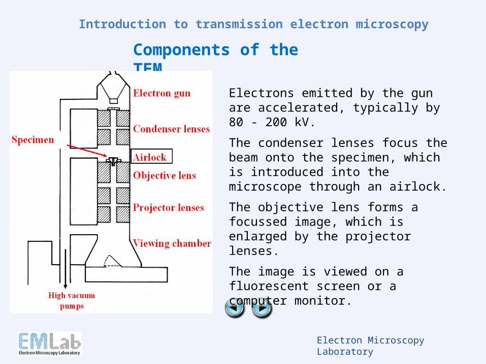
Electrons emitted by the gun are accelerated, typically by 80 - 200 kV.
The condenser lenses focus the beam onto the specimen, which is introduced into the microscope through an airlock.
The objective lens forms a focussed image, which is enlarged by the projector lenses.
The image is viewed on a fluorescent screen or a computer monitor.
Components of the TEM
Electron Microscopy Laboratory
Introduction to transmission electron microscopy
The electron source
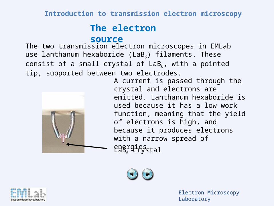
LaB6 crystal
The two transmission electron microscopes in EMLab use lanthanum hexaboride (LaB6) filaments. These consist of a small crystal of LaB6, with a pointed tip, supported between two electrodes.
A current is passed through the crystal and electrons are emitted. Lanthanum hexaboride is used because it has a low work function, meaning that the yield of electrons is high, and because it produces electrons with a narrow spread of energies.
Electron Microscopy Laboratory
Introduction to transmission electron microscopy
Accelerating voltage
Electrons emitted by the filament are accelerated by a series of anodes. For transmission electron microscopy, accelerating voltages typically range from 60 kV to 200 kV. Higher accelerating voltages give higher resolution, but less contrast. High accelerating voltages can also result in greater specimen damage. For these reasons, studies of biological samples tend to employ low accelerating voltages (60 kV to 100 kV), while studies of inorganic materials, which often require higher resolution, usually employ an accelerating voltage of 200 kV.
Electron Microscopy Laboratory
Introduction to transmission electron microscopy
Electromagnetic lenses
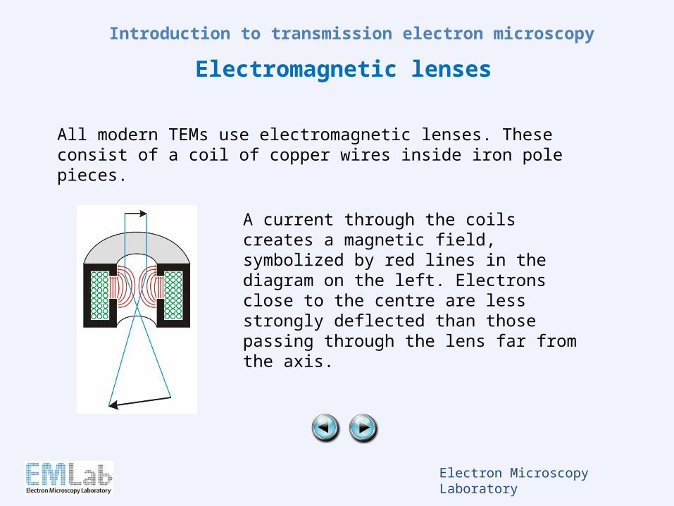
All modern TEMs use electromagnetic lenses. These consist of a coil of copper wires inside iron pole pieces.
A current through the coils creates a magnetic field, symbolized by red lines in the diagram on the left. Electrons close to the centre are less strongly deflected than those passing through the lens far from the axis.
Electron Microscopy Laboratory
Introduction to transmission electron microscopy
Apertures
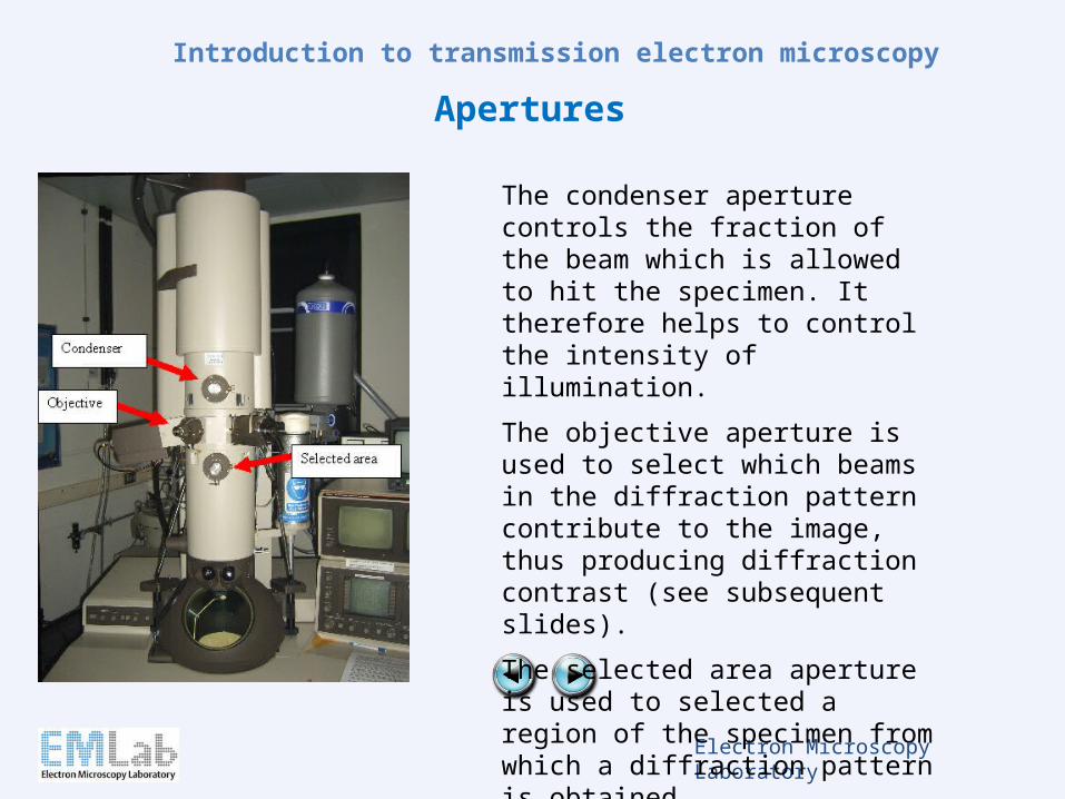
The condenser aperture controls the fraction of the beam which is allowed to hit the specimen. It therefore helps to control the intensity of illumination.
The objective aperture is used to select which beams in the diffraction pattern contribute to the image, thus producing diffraction contrast (see subsequent slides).
The selected area aperture is used to selected a region of the specimen from which a diffraction pattern is obtained.
Electron Microscopy Laboratory
Introduction to transmission electron microscopy
Electron diffraction in the TEM
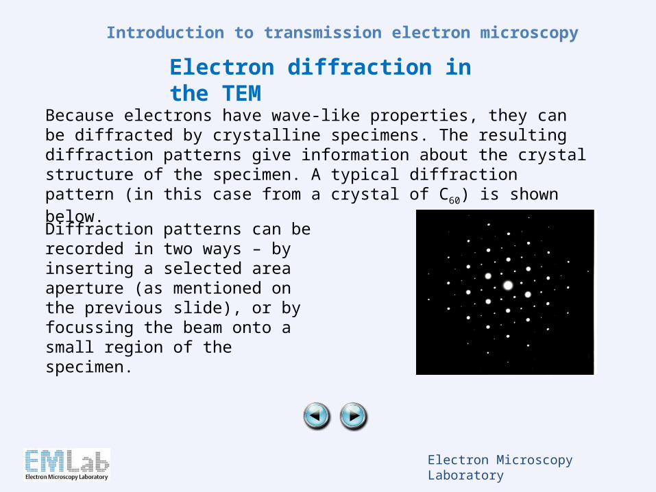
Because electrons have wave-like properties, they can be diffracted by crystalline specimens. The resulting diffraction patterns give information about the crystal structure of the specimen. A typical diffraction pattern (in this case from a crystal of C60) is shown below.
Diffraction patterns can be recorded in two ways – by inserting a selected area aperture (as mentioned on the previous slide), or by focussing the beam onto a small region of the specimen.
Electron Microscopy Laboratory
Introduction to transmission electron microscopy
Contrast in the TEM: Diffraction contrast - 1
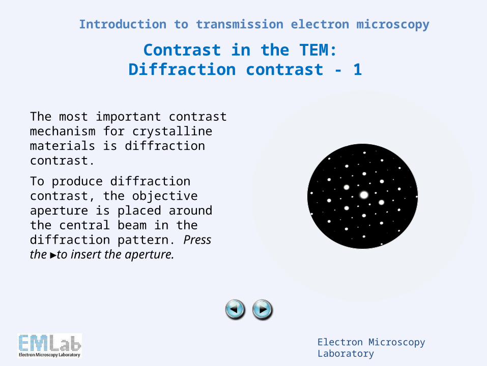
The most important contrast mechanism for crystalline materials is diffraction contrast.
To produce diffraction contrast, the objective aperture is placed around the central beam in the diffraction pattern. Press the ►to insert the aperture.
Electron Microscopy Laboratory
Introduction to transmission electron microscopy
Contrast in the TEM: Diffraction contrast - 1
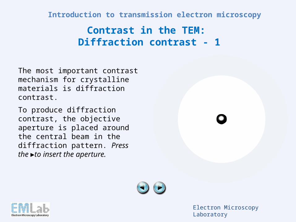
The most important contrast mechanism for crystalline materials is diffraction contrast.
To produce diffraction contrast, the objective aperture is placed around the central beam in the diffraction pattern. Press the ►to insert the aperture.
Electron Microscopy Laboratory
Introduction to transmission electron microscopy
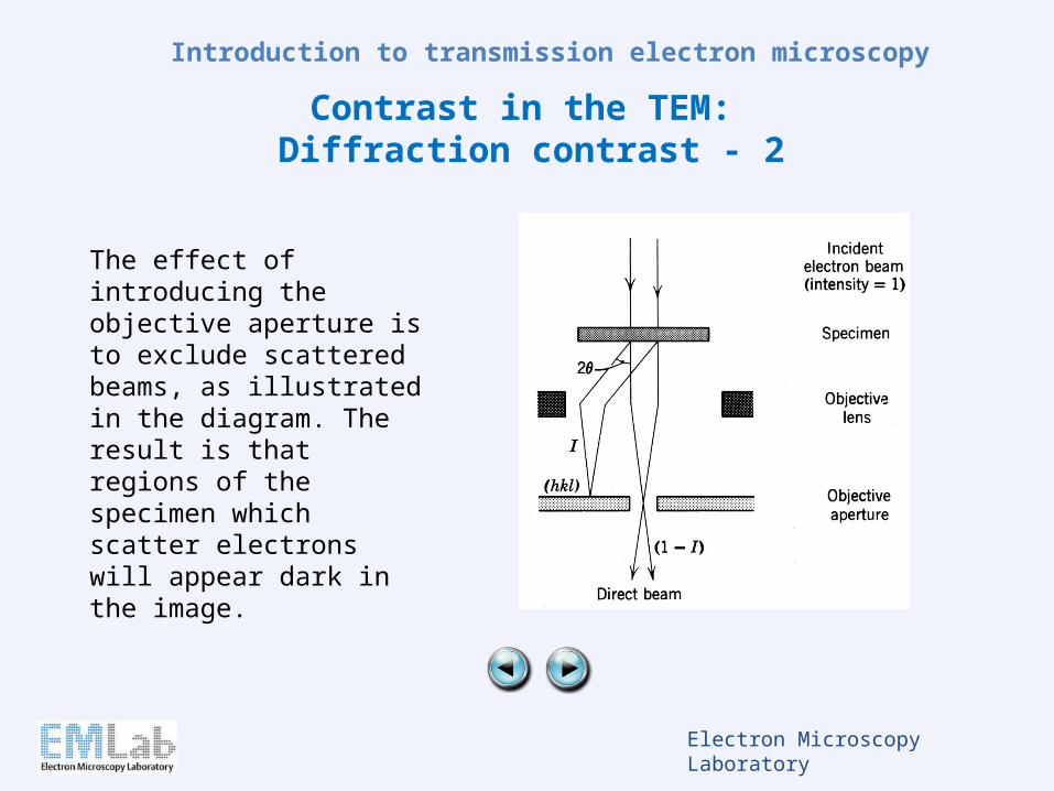
Contrast in the TEM: Diffraction contrast - 2
The effect of introducing the objective aperture is to exclude scattered beams, as illustrated in the diagram. The result is that regions of the specimen which scatter electrons will appear dark in the image.
Electron Microscopy Laboratory
Introduction to transmission electron microscopy
Specimen preparation for TEM - 1
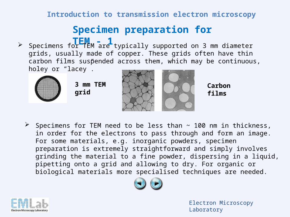
Specimens for TEM are typically supported on 3 mm diameter grids, usually made of copper. These grids often have thin carbon films suspended across them, which may be continuous, holey or “lacey”.
3 mm TEM grid
Specimens for TEM need to be less than ~ 100 nm in thickness, in order for the electrons to pass through and form an image. For some materials, e.g. inorganic powders, specimen preparation is extremely straightforward and simply involves grinding the material to a fine powder, dispersing in a liquid, pipetting onto a grid and allowing to dry. For organic or biological materials more specialised techniques are needed.
Carbon films
Electron Microscopy Laboratory
Introduction to transmission electron microscopy
Specimen preparation for TEM - 2
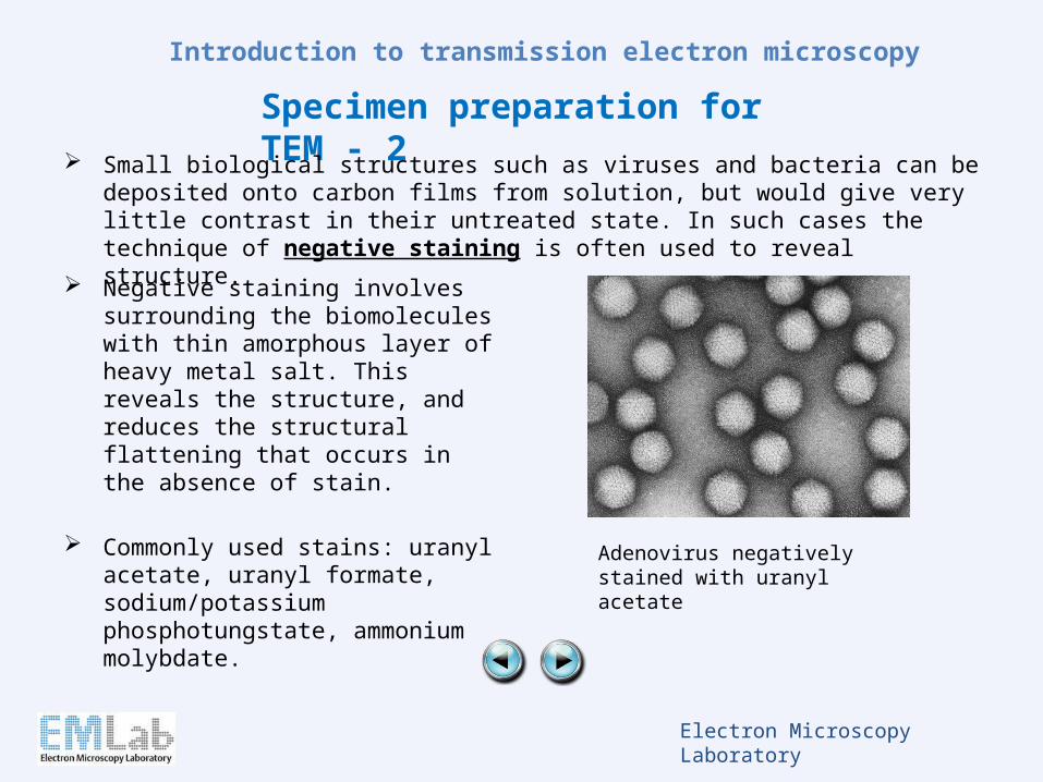
Small biological structures such as viruses and bacteria can be deposited onto carbon films from solution, but would give very little contrast in their untreated state. In such cases the technique of negative staining is often used to reveal structure.
Negative staining involves surrounding the biomolecules with thin amorphous layer of heavy metal salt. This reveals the structure, and reduces the structural flattening that occurs in the absence of stain.
Commonly used stains: uranyl acetate, uranyl formate, sodium/potassium phosphotungstate, ammonium molybdate.
Adenovirus negatively stained with uranyl acetate
Electron Microscopy Laboratory
Introduction to transmission electron microscopy
Specimen preparation for TEM - 3
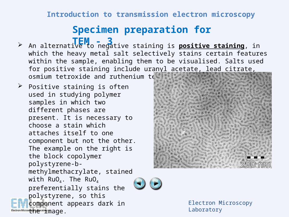
An alternative to negative staining is positive staining, in which the heavy metal salt selectively stains certain features within the sample, enabling them to be visualised. Salts used for positive staining include uranyl acetate, lead citrate, osmium tetroxide and ruthenium tetroxide.
Positive staining is often used in studying polymer samples in which two different phases are present. It is necessary to choose a stain which attaches itself to one component but not the other. The example on the right is the block copolymer polystyrene-b-methylmethacrylate, stained with RuO4. The RuO4 preferentially stains the polystyrene, so this component appears dark in the image.
Electron Microscopy Laboratory
Introduction to transmission electron microscopy
Specimen preparation for TEM - 4
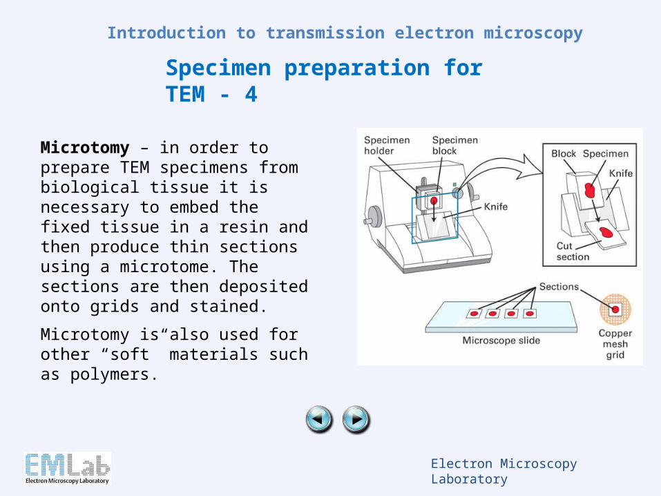
Microtomy – in order to prepare TEM specimens from biological tissue it is necessary to embed the fixed tissue in a resin and then produce thin sections using a microtome. The sections are then deposited onto grids and stained.
Microtomy is also used for other “soft” materials such as polymers.
Electron Microscopy Laboratory
Introduction to transmission electron microscopy
Astigmatism 1
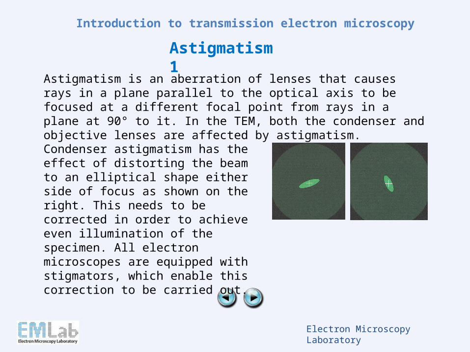
Astigmatism is an aberration of lenses that causes rays in a plane parallel to the optical axis to be focused at a different focal point from rays in a plane at 90° to it. In the TEM, both the condenser and objective lenses are affected by astigmatism.
Condenser astigmatism has the effect of distorting the beam to an elliptical shape either side of focus as shown on the right. This needs to be corrected in order to achieve even illumination of the specimen. All electron microscopes are equipped with stigmators, which enable this correction to be carried out.
Electron Microscopy Laboratory
Introduction to transmission electron microscopy
Astigmatism 2
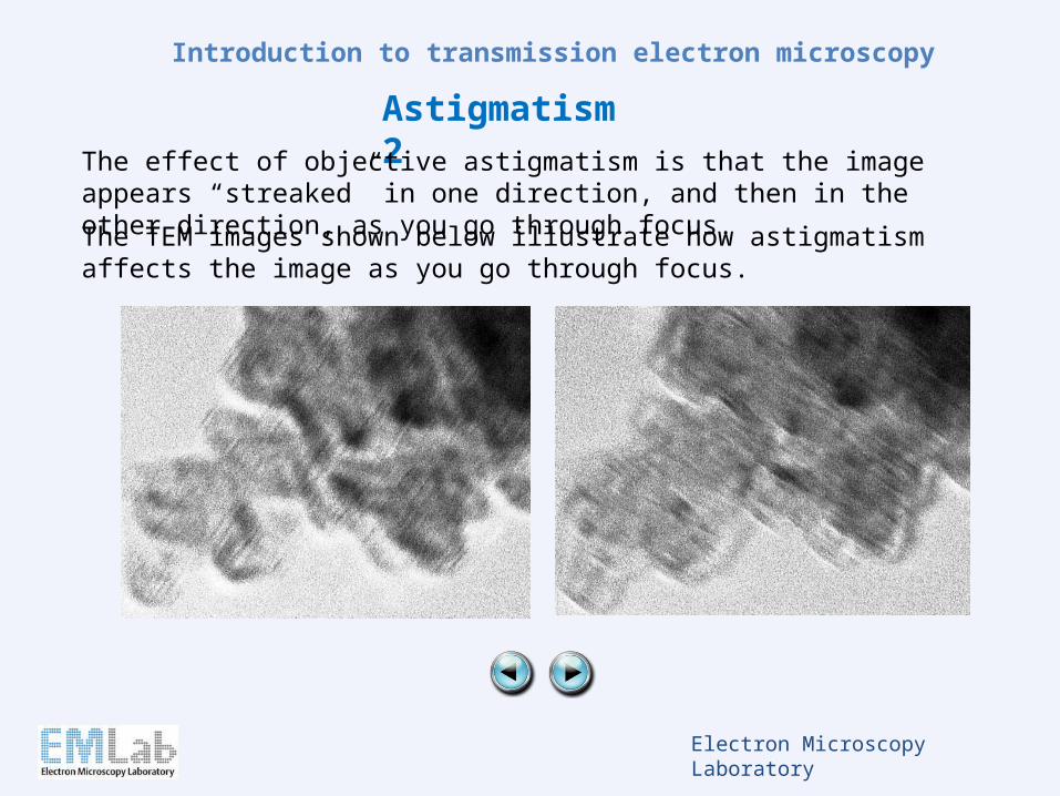
The TEM images shown below illustrate how astigmatism affects the image as you go through focus.
The effect of objective astigmatism is that the image appears “streaked” in one direction, and then in the other direction, as you go through focus.
Electron Microscopy Laboratory
Introduction to transmission electron microscopy
Spherical aberration
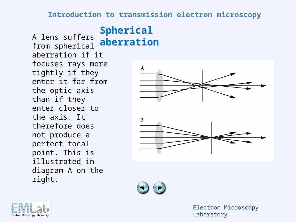
A lens suffers from spherical aberration if it focuses rays more tightly if they enter it far from the optic axis than if they enter closer to the axis. It therefore does not produce a perfect focal point. This is illustrated in diagram A on the right.
Electron Microscopy Laboratory
Introduction to transmission electron microscopy
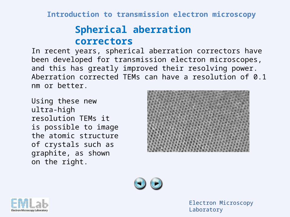
Spherical aberration correctors
In recent years, spherical aberration correctors have been developed for transmission electron microscopes, and this has greatly improved their resolving power. Aberration corrected TEMs can have a resolution of 0.1 nm or better.
Using these new ultra-high resolution TEMs it is possible to image the atomic structure of crystals such as graphite, as shown on the right.
Electron Microscopy Laboratory
Introduction to transmission electron microscopy
Chromatic aberration
Chromatic aberration is caused by a lens having a different refractive index for different electron energies. It is present in all electron lenses, but can be reduced by minimising the energy spread of the electron source. Field emission sources have the lowest energy spread. There is currently interest in developing chromatic aberration correctors for TEM, but this is still at quite an early stage.
Electron Microscopy Laboratory
Introduction to transmission electron microscopy
Further information
The recommended book for this course is "Electron microscopy and analysis", by Goodhew, Humphreys and Beanland.
Peter Harris and other members of EMLab staff will be happy to answer your questions.
Links to some useful websites can be found on the “TEM online course” page.
You will be required to take a short online test, available via Blackboard, to assess whether you have taken in the information in this course.