Embed Size (px)
Citation preview
ARLreview 2001 page 1
Return to Table of Contents
Electron Beam – Physical Vapor Deposition Coating○ ○ ○ ○ ○ ○ ○ ○ ○ ○ ○ ○ ○ ○ ○ ○ ○ ○ ○ ○ ○ ○ ○ ○ ○ ○ ○ ○ ○ ○ ○ ○ ○ ○ ○ ○ ○ ○ ○ ○ ○ ○ ○ ○ ○ ○ ○ ○ ○ ○ ○ ○ ○ ○ ○ ○ ○ ○ ○ ○ ○ ○ ○ ○
Jogender SinghARL Penn State
ABSTRACTThe Applied Research Laboratory at Penn State is hometo iMAST, the Navy ManTech Institute for Manufacturingand Sustainment Technologies. An iMAST/ARL coretechnology is electron beam – physical vapor deposition(EB–PVD). This industrial scale EB–PVD facility is aunique research facility and capability for developingadvanced materials and coatings for a wide range ofindustrial applications, including turbine, auto, andaerospace. The mission of the core technology is to provideleadership in transferring the technology to private industryfor Navy applications. Varieties of ceramic and metalliccoatings have been produced by the EB-PVD facility sinceit became operational in January 1998. A summary of theseaccomplishments is given below.
The EB-PVD ProcessPenn State’s industrial pilot Sciaky EB-PVD unit has six electronbeam guns, four of which are used to evaporate the coatingmaterials and two of which are used to preheat the substrate tofacilitate coating adhesion (Figure 1). Each gun has a 45 kWcapacity. The chamber will accommodate up to three ingotsranging in size from 49–68 mm in diameter and 450 mm long.The overall dimension of the production unit is about 1 cubicmeter. (The maximum diameter of the substrate—with verticalrotation—that can be accommodated is about 400 mm; it can berotated at a speed of 5.5–110 rpm with a maximum load of about100 Kg.) The unit also has a horizontal sample holder with athree-axis part manipulator: two rotary axes of 0-14 rpm and a0–4,000 mm/min translation axis. It can carry samples weighingup to 20 kg. Since EB-PVD is primarily a line-of-sight process,uniform coatings of complex parts (such as turbine blades) canbe accomplished by continuously rotating the part during thecoating process.
Advantages of the EB-PVD ProcessThe EB-PVD process offers extensive possibilities for controllingvariations in the structure and composition of condensed materials.For example, the coating compositions can be varied continuously,as in so-called functional graded coatings (FGC). Also, coatingscomprised of alternating layers of different compositions can bemade. These multilayered coatings can be applied on top of theFGC. The EB-PVD process offers many desirable characteristics
such as relatively high deposition rates (up to 150 µm/minutewith an evaporation rate of ~10–15 Kg/hour), dense coatings,controlled composition and microstructure, low contamination, andhigh thermal efficiency. Coatings produced by the EB-PVD processusually have a good surface finish and a uniform microstructure. Themicrostructure and composition of the coating can be easily alteredby manipulating the process parameters and ingot compositions.Thus, multilayered ceramic/metallic coatings can be readily formed,and various metallic and ceramic coatings (oxides, carbides, andnitrides) can be deposited at relatively low temperatures. Evenelements with low vapor pressure such as molybdenum, tungsten,and carbon are readily evaporated by this process.
The attachment of an ion beam source to the EB-PVD systemoffers additional benefits such as forming dense coatings withimproved microstructure, interfaces, and adhesion. In addition,textured coatings, which are desirable in many applications, canbe obtained. The state of the internal stresses can be changed(i.e., from tensile to compressive) by the forcible injection of ahigh-energy ion (100-1,000 eV). A high-energy ion beam (as asource of energy) is quite often used to clean the surface of thespecimen inside the vacuum chamber prior to coating. Thecleaning enhances the bonding strength between the coating andthe substrate.
Figure 1. Schematic diagram of the ion-beam-assisted EB-PVD unit.
ARLreview 2001 page 2
Return to Table of Contents
Success storiesSince the EB-PVD unit became operational, a variety of coatingshave been produced for a wide range of applications including turbine,auto, and aerospace.
LOCALIZED REPAIR AND ALTERNATIVE TOHARD CHROMIUM ELECTROPLATINGChromium (Cr) electroplating is known to be an environmentallyhazardous process. The Cr plating process is normally used in areaswhere wear, corrosion, and oxidation (<600°C) are factors inequipment performance. An environmentally friendly process thatprovides the same or improved wear, corrosion, and oxidationprotection is required. To achieve this goal, two challenges must bemet: (1) identify potential candidate materials for the replacementof Cr and (2) develop/identify a process for applying the candidatecoating materials. The selection of the alternative coating processeswill depend upon the application and requirements including surfacefinish, wear-resistance properties, fatigue, and thermal properties.
A unique characteristic of EB-PVD is that it meets the above-mentioned challenges and can be used to tailor coatings for specificapplications. With the EB-PVD process, corrosion-resistant materialscan be applied economically on the surface where they are mostneeded. Applications for these coatings range from brass lightingfixtures to landing gear and other components of aircraft andhelicopters. the IBAD EB-PVD process offers additional flexibilityin repairing localized damage in landing gears—a task that cannotbe done by any other processes without affecting the physical andmechanical properties of the base material. The significant advantageof using IBAD along with EB-PVD is the capability to enhance themetallurgical bonding of the coating with the substrate at a relativelylow temperature. For instance, EB-PVD chromium coatings were
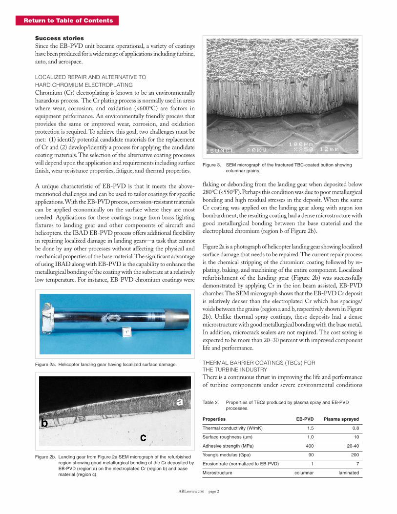
flaking or debonding from the landing gear when deposited below280°C (<550°F). Perhaps this condition was due to poor metallurgicalbonding and high residual stresses in the deposit. When the sameCr coating was applied on the landing gear along with argon ionbombardment, the resulting coating had a dense microstructure withgood metallurgical bonding between the base material and theelectroplated chromium (region b of Figure 2b).
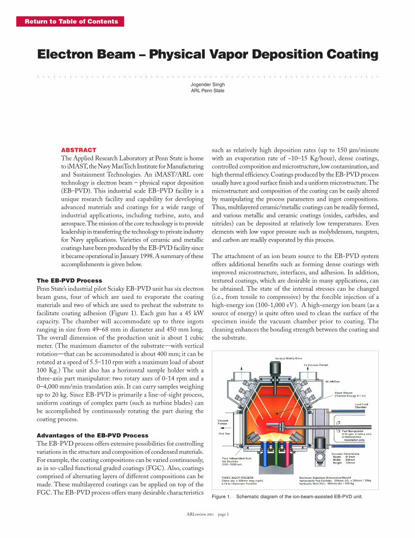
Figure 2a is a photograph of helicopter landing gear showing localizedsurface damage that needs to be repaired. The current repair processis the chemical stripping of the chromium coating followed by re-plating, baking, and machining of the entire component. Localizedrefurbishment of the landing gear (Figure 2b) was successfullydemonstrated by applying Cr in the ion beam assisted, EB-PVDchamber. The SEM micrograph shows that the EB-PVD Cr depositis relatively denser than the electroplated Cr which has spacings/voids between the grains (region a and b, respectively shown in Figure2b). Unlike thermal spray coatings, these deposits had a densemicrostructure with good metallurgical bonding with the base metal.In addition, microcrack sealers are not required. The cost saving isexpected to be more than 20–30 percent with improved componentlife and performance.
THERMAL BARRIER COATINGS (TBCs) FORTHE TURBINE INDUSTRYThere is a continuous thrust in improving the life and performanceof turbine components under severe environmental conditions
Figure 2b. Landing gear from Figure 2a SEM micrograph of the refurbishedregion showing good metallurgical bonding of the Cr deposited byEB-PVD (region a) on the electroplated Cr (region b) and basematerial (region c).
Figure 3. SEM micrograph of the fractured TBC-coated button showingcolumnar grains.
Table 2. Properties of TBCs produced by plasma spray and EB-PVDprocesses.
Properties EB-PVD Plasma sprayed
Thermal conductivity (W/mK) 1.5 0.8
Surface roughness (µm) 1.0 10
Adhesive strength (MPa) 400 20-40
Young’s modulus (Gpa) 90 200
Erosion rate (normalized to EB-PVD) 1 7
Microstructure columnar laminated
Figure 2a. Helicopter landing gear having localized surface damage.
ARLreview 2001 page 3
Return to Table of Contents
including erosion, oxidation, and corrosion.4,5 The life of componentshas been increased by applying TBCs by either plasma spray or EB-PVD processes. Each process has advantages and disadvantages(Table 2). For instance, the thermal conductivity of the plasma-sprayed TBCs is about 60 percent lower than the bulk value, due topresence of porosity between the laminated grains. In contrast, thethermal conductivity of TBCs applied by EB-PVD is higher thanthe plasma spray coatings. The higher thermal conductivity in theEB-PVD TBCs is due to limited porosity present in the individualcolumnar grains. The porosity in TBCs is mainly present betweenthe columnar grains (Figure 3). In spite of higher thermal conductivity,TBCs applied by EB-PVD are preferred over plasma-sprayed TBCsdue to their smooth surface finish, better strain tolerance, bettererosion-resistance properties, and improved metallurgical bondingwith the substrate. In spite of significant advancement in the EB-PVD coating technology, there are still challenges in producing lowthermal conductivity EB-PVD TBCs. Future thrusts are in producinga low-conductivity EB-PVD TBC by altering the microstructure andcreating micro-porosity within the columnar grains, or in providing newmaterials with different compositions and functional graded coatings.
COATINGS FOR MACHINING TOOLS ANDFORGING DIE INDUSTRIESMetallic borides, carbides, nitrides, and oxides have long been knownto be very hard, wear-resistant materials. Applying these hard coatingsto tool steels and tungsten carbide-cobalt cutting inserts can increasethe tool life by several hundred percent (400-600 percent), reducingcosts associated with tool procurement, set-up time, and machinedowntime. Wear-resistant coatings are often characterized as havinghigh melting temperatures as well as high hardness values. However,it is important to note that the coating performance depends onseveral factors including coating material, the deposition process,and machining conditions. The deposition process and parametersoften dictate the coating’s microstructure features (i.e., grain size,degree of texture, density, etc.) and thus its properties.
The machining of titanium and nickel-based alloys is very difficultand challenging. To improve the efficiency and life of cutting tools,
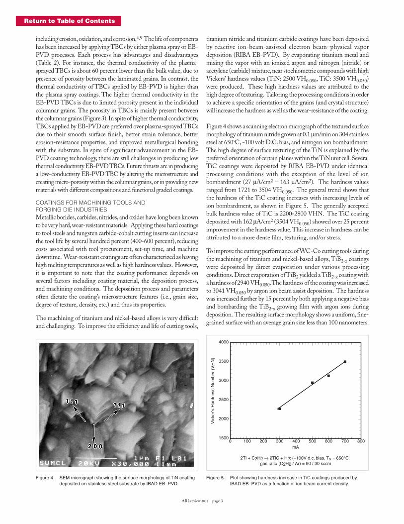
titanium nitride and titanium carbide coatings have been depositedby reactive ion-beam-assisted electron beam–physical vapordeposition (RIBA EB-PVD). By evaporating titanium metal andmixing the vapor with an ionized argon and nitrogen (nitride) oracetylene (carbide) mixture, near stochiometric compounds with highVickers’ hardness values (TiN: 2500 VH0.050, TiC: 3500 VH0.050)were produced. These high hardness values are attributed to thehigh degree of texturing. Tailoring the processing conditions in orderto achieve a specific orientation of the grains (and crystal structure)will increase the hardness as well as the wear-resistance of the coating.
Figure 4 shows a scanning electron micrograph of the textured surfacemorphology of titanium nitride grown at 0.1 µm/min on 304 stainlesssteel at 650°C, -100 volt D.C. bias, and nitrogen ion bombardment.The high degree of surface texturing of the TiN is explained by thepreferred orientation of certain planes within the TiN unit cell. SeveralTiC coatings were deposited by RIBA EB-PVD under identicalprocessing conditions with the exception of the level of ionbombardment (27 µA/cm2 – 163 µA/cm2). The hardness valuesranged from 1721 to 3504 VH0.050. The general trend shows thatthe hardness of the TiC coating increases with increasing levels ofion bombardment, as shown in Figure 5. The generally acceptedbulk hardness value of TiC is 2200-2800 VHN. The TiC coatingdeposited with 162 µA/cm2 (3504 VH0.050) showed over 25 percentimprovement in the hardness value. This increase in hardness can beattributed to a more dense film, texturing, and/or stress.
To improve the cutting performance of WC-Co cutting tools duringthe machining of titanium and nickel-based alloys, TiB2-x coatingswere deposited by direct evaporation under various processingconditions. Direct evaporation of TiB2 yielded a TiB2-x coating witha hardness of 2940 VH0.050. The hardness of the coating was increasedto 3041 VH0.050 by argon ion beam assist deposition. The hardnesswas increased further by 15 percent by both applying a negative biasand bombarding the TiB2-x growing film with argon ions duringdeposition. The resulting surface morphology shows a uniform, fine-grained surface with an average grain size less than 100 nanometers.
Figure 4. SEM micrograph showing the surface morphology of TiN coatingdeposited on stainless steel substrate by IBAD EB–PVD.
Figure 5. Plot showing hardness increase in TiC coatings produced byIBAD EB–PVD as a function of ion beam current density.
4000
3500
3000
2500
2000
15000 100 200 300 400 500 600 700 800
Vic
ker’s
Har
dnes
s N
umbe
r (V
HN
)
mA
2Ti + C2H2 → 2TiC + H2; (–100V d.c. bias, Ts = 650°C, gas ratio (C2H2 / Ar) = 90 / 30 sccm
ARLreview 2001 page 4
Return to Table of Contents
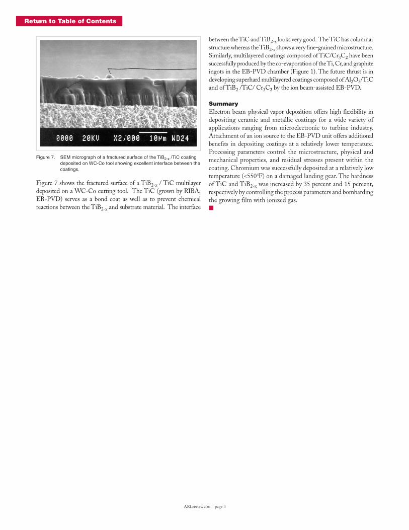
Figure 7 shows the fractured surface of a TiB2-x / TiC multilayerdeposited on a WC-Co cutting tool. The TiC (grown by RIBA,EB-PVD) serves as a bond coat as well as to prevent chemicalreactions between the TiB2-x and substrate material. The interface
Figure 7. SEM micrograph of a fractured surface of the TiB2-x /TiC coatingdeposited on WC-Co tool showing excellent interface between thecoatings.
between the TiC and TiB2-x looks very good. The TiC has columnarstructure whereas the TiB2-x shows a very fine-grained microstructure.Similarly, multilayered coatings composed of TiC/Cr3C2 have beensuccessfully produced by the co-evaporation of the Ti, Cr, and graphiteingots in the EB-PVD chamber (Figure 1). The future thrust is indeveloping superhard multilayered coatings composed of Al2O3/TiCand of TiB2 /TiC/ Cr3C2 by the ion beam-assisted EB-PVD.
SummaryElectron beam-physical vapor deposition offers high flexibility indepositing ceramic and metallic coatings for a wide variety ofapplications ranging from microelectronic to turbine industry.Attachment of an ion source to the EB-PVD unit offers additionalbenefits in depositing coatings at a relatively lower temperature.Processing parameters control the microstructure, physical andmechanical properties, and residual stresses present within thecoating. Chromium was successfully deposited at a relatively lowtemperature (<550°F) on a damaged landing gear. The hardnessof TiC and TiB2-x was increased by 35 percent and 15 percent,respectively by controlling the process parameters and bombardingthe growing film with ionized gas.�