Embed Size (px)
Citation preview
Electron-Beam-Induced Fracture of Polymers
J. T. DICKINSON, M. L. KLAKKEN, M. H. MILES, and L. C. JENSEN, Department of Physics, Washington State University,
Pu 1 lman, Washington 991 64-2814
Synopsis
When a notched polymeric material is stressed, the notch opens into a wide crack tip, exposing a region of high stress concentration. The consequences of electron bombardment of the tip of such a stressed material under vacuum are explored here for the first time. Evidence is presented for electron-induced crack growth at stress far below that needed for crack growth due to stress alone. The electron current densities used in these experiments are sufficiently small that thermal heating of the zone near the crack tip is minimal. To provide information on the phenomena involved, we present simultaneous measurements of electron current, gas pressure, and sample load in response to periodic bombardment of the sample. Experiments involving the bombardment of un-notched polymers under stress are also described. Fractog- raphy of the unique structures obtained by fracture due to the combination of electron bom- bardment and stress are presented and interpreted in terms of a crosslinking mechanism.
INTRODUCTION When a polymer is bombarded by highenergy electrons, energy is de-
posited in the material owing to the inelastic collisions that occur. These events cause ionization, broken bonds, and vibrational excitations of the molecules. The chemical effects that can result from these events include additional polymerization, crosslinking, and branching of the polymer, all of which tend to increase the “strength” of the material in the region of bombardment. Likewise, bond scissions, molecular dissociation (via elec- tronic excitations), electron-stimulated desorption of ions and neutral spe- cies (again, via electronic excitations), as well as thermal degradation and gas evolution (due to a temperature rise in the material being bombarded) can occur, all of which tend to “weaken” the material.
This paper explores the simple question: What happens when a combi- nation of stress and electron bombardment is applied at the tip of a crack in a polymer? The primary motivation for such an experiment is to examine the consequences of fracture in a high-energy environment. Situations such as stressed materials exposed to radiation, combustion of rocket propellents, and materials exposed to plasma environments are all of interest. Second, the use of e - beam excitation of the crack tip may further our understanding of the physics of fracture by eventual selective and controlled bond breaking and/or activated stress-dependent chemistry. Eventually the hope is to at- tempt various electron spectroscopies, e.g. electron energy-loss spectroscopy, on stressed molecules to provide useful information about the state of these molecules. Obviously, we view the work presented here as preliminary.
Models of fracture of polymeric solids and elastomers have been reviewed by Andrews’ and Gent.2 A continuum fracture theory expressed in terms
Journal of Polymer Science: Polymer Physics Edition, Vol. 23, 2273-2293 (1985) @ 1985 John Wiley & Sons, Inc. CCC 009&1273/85/112273-21$04.00
2274 DICKINSON ET AL.
of a characteristic energy for tearing3 and the strain concentration at the crack tip4 has been developed by Thomas and co-workers. The continuum theory of fracture seems compatible with a molecular theory' in that the different initial assumptions both appear capable of adequately describing the experimental results. However, as fracture investigations become more sophisticated, it is expected that molecular understanding will become in- creasingly more important.
This paper will concentrate primarily on the mechanical response of the material subjected to stress and electron bombardment. The polymers in- cluded here are unfilled polyisoprene, a 50-50 copolymer of 3,3,bis(azi- domethy1)oxetane and tetrahydrofuran (BAMO/THFta model energetic binder for rocket propellent, filled butyl rubber, and polyethylene.
EXPERIMENTAL Rectangular test specimens of several polymeric materials were mounted
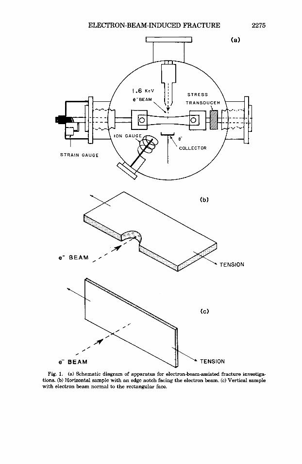
in a vacuum system equipped for straining materials in tension. Figure l(a) shows a schematic diagram of the apparatus. Two sample orientations that were studied are shown in Figures l(b) and l(c). The usual test involved a notched sample mounted horizontally with the notch facing the electron beam [Fig. l(b)]. The materials chosen were deformed to yield an open, U- shaped crack, allowing convenient e- beam bombardment in the region of high stress.
The samples were subjected to a constant strain rate of 1.2%/s. A load cell (Sensotec model 11) was used to monitor the force applied to the sample. Most of the tests were carried out at a pressure of Pa. A Varian electron gun was mounted so that the electron beam would strike the sample at or near the focal point. The spot size was approximately 3 mm in diameter. The electron beam could be deflected with appropriate voltages applied to the deflection plates. The kinetic energy of the incident electrons was 1.6 keV. The electron currents were generally between 10 and 20 PA. In most experiments the time that the beam was actually on the sample was min- imized to avoid the buildup of surface charge which would tend to reduce the current density bombarding the polymer surface.
Some of the samples were in the form of un-notched thin sheets and were mounted vertically, with the e- beam striking the rectangular face with normal incidence [Fig. l(c)]. In this latter mode, the influence of uniaxial tension on the time required for the e- beam to penetrate through the specimen was examined. The response of the sample was generally like fracture; furthermore, any displacement of the e- beam on the sample promoted crack growth in that direction.
In most of the experiments, a metal collector mounted behind the sample was used to measure the electron current by use of an electrometer. In addition, if the sample was partially or completely blocking the e- beam, the time at which the e- beam came on, off, or penetrated through the sample could be determined quite accurately. The rise in pressure in the vacuum system was frequently measured by means of a nude ionization gauge. The appropriate signals from the various transducers were all si-
ELECTRON-BEAM-INDUCED FRACTURE 2275
(a)
0 0
0
e- B E A M TENSION
Fig. 1. (a) Schematic diagram of apparatus for electron-beam-assisted fracture investiga- tions. (b) Horizontal sample with an edge notch facing the electron beam. (c) Vertical sample with electron beam normal to the rectangular face.
2276 DICKINSON ET AL.
multaneously digitized with 0.1-s time resolution by using a LeCroy Data Acquisition System and stored on disk for later analysis and plotting.
The samples were cut from sheets of polymer. The polyisoprene (PI), provided by €3. M. Leeper, Alza Corporation, were replicate plaques of Good- year Natsyn 2200 crosslinked with Hercules Di-Cup R. After a 20-min cure at 165”C, the plaques were extracted with boiling acetone. Sample cross sections were 1 x 10 mm with a single-edge notch of 1.5 mm. These samples would generally start to rupture at approximately 6.5 N of applied force with a strain of about 260%.
The BAMO/THF samples, provided by P. Majewski and Y. Gupta, Wash- ington State University, consisted of BAMO/THF reacted with tolylene 2,6diisocyanide, and crosslinked with 1-1-1 tris(hydroxymethy1)ethane by using dibutyl tin dilaurate as a catalyst. Curing took place at 60°C for several days. The BAMO/THF sample cross sections were 3 X 12 mm and were notched to a depth of 1 mm. These samples started to fail at an applied force of about 11 N.
The butyl rubber (IIR) samples were cut from commercial sheets (Baxter Rubber Company) and each sample had a cross section of 3 x 9 mm with a single-edge notch of 1 mm. These samples were filled with carbon black and generally started to fail at an applied load of 32 N with a strain of about 330%.
The polyethylene (PE) samples were from commercial sheets of linear high-density polyethylene (U. S. Industrial Chemicals LR 20175) of density 0.95 g/cm3 and characteristic melt index 0.1. Sample cross sections were 50 pm x 10 mm.
Fracture surfaces of all materials were prepared for scanning electron microscopy (SEMI by careful cutting and mounting of sections of the sample. Gold coatings 300 A thick were sputtered onto the specimens prior to ex- amination in the microscope.
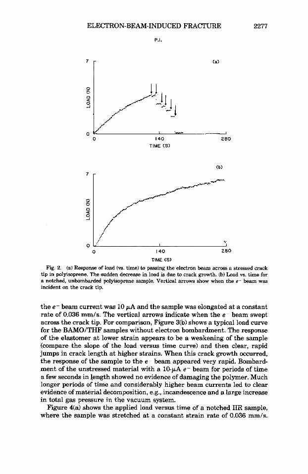
RESULTS The applied load versus time of a notched PI sample, elongated at a
constant strain rate of 0.036 mm/s, is shown in Figure 2(a). The vertical arrows represent the times when the electron beam (10 PA) passed over the notched crack tip in this “pit and the pendulum” experiment. The response of the sample to the passing e- beam consisted of dramatic jumps of the crack with an accompanying drop in the force. For a time scale on the order of seconds, the response appeared to be instantaneous. Earlier experiments on unstressed PI or PI stressed into the elastic region only showed no effect of cutting or no visible damage to the PI sample at these beam currents and exposure times. The last drop in load corresponds to the final rupture of the specimen. At higher electron currents, the response was found to be larger jumps in crack length for a given strain. Figure 2(b) shows a typical load versus time curve for an identical notched sample strained in the same manner as above but without electron bombardment. As shown, the time and therefore the extension at failure was considerably longer.
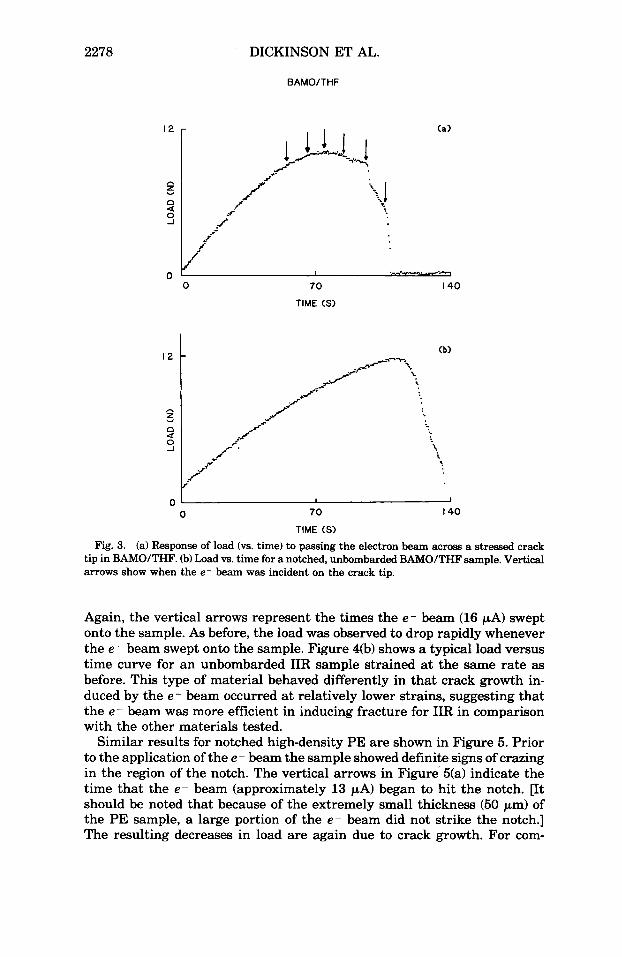
Similar data for notched BAMO/THF are shown in Figure 3(a), where
ELECTRON-BEAM-INDUCED FRACTURE 2277
P.I.
TIME (S)
0 I40
TIME (S)
200
Fig. 2. (a) Response of load (vs. time) to passing'the electron beam across a stressed crack tip in polyisoprene. The sudden decrease in load is due to crack growth. @) Load vs. time for a notched, unbombarded polyisoprene sample. Vertical arrows show when the e- beam was incident on the crack tip.
the e- beam current was 10 pA and the sample was elongated at a constant rate of 0.036 mm/s. The vertical arrows indicate when the e- beam swept across the crack tip. For comparison, Figure 3(b) shows a typical load curve for the BAMO/THF samples without electron bombardment. The response of the elastomer at lower strain appears to be a weakening of the sample (compare the slope of the load versus time curve) and then clear, rapid jumps in crack length at higher strains. When this crack growth occurred, the response of the sample to the e- beam appeared very rapid. Bombard- ment of the unstressed material with a 10-pA e- beam for periods of time a few seconds in length showed no evidence of damaging the polymer. Much longer periods of time and considerably higher beam currents led to clear evidence of material decomposition, e.g., incandescence and a large increase in total gas pressure in the vacuum system.
Figure 4(a) shows the applied load versus time of a notched IIR sample, where the sample was stretched at a constant strain rate of 0.036 mm/s.
2278 DICKINSON ET
BAMO/THF
AL.
(a)
0 70
TIME ( S )
I40
I 1
0 70 I40
TIME ( S )
Fig. 3. (a) Response of load (vs. time) to passing the electron beam across a stressed crack tip in BAMOITHF. (b) Load vs. time for a notched, unbombarded BAMO/THF sample. Vertical arrows show when the e- beam was incident on the crack tip.
Again, the vertical arrows represent the times the e - beam (16 PA) swept onto the sample. As before, the load was observed to drop rapidly whenever the e - beam swept onto the sample. Figure 4(b) shows a typical load versus time curve for an unbombarded IIR sample strained at the same rate as before. This type of material behaved differently in that crack growth in- duced by the e - beam occurred at relatively lower strains, suggesting that the e - beam was more efficient in inducing fracture for IIR in comparison with the other materials tested.
Similar results for notched high-density PE are shown in Figure 5. Prior to the application of the e - beam the sample showed definite signs of crazing in the region of the notch. The vertical arrows in Figure 5(a) indicate the time that the e - beam (approximately 13 pA) began to hit the notch. [It should be noted that because of the extremely small thickness (50 pm) of the PE sample, a large portion of the e - beam did not strike the notch.] The resulting decreases in load are again due to crack growth. For com-

ELECTRON-BEAM-INDUCED FRACTURE
IIR
2279
0 250
TIME(S)
500
-. o : I
0 250 500
TIME (S) Fig. 4. (a) Load vs. time for a notched butyl rubber sample with an e- beam sweeping
acrosa the crack tip. (b) Load vs. time for a notched, unbombarded butyl rubber sample. Vertical arrows represent the time the e- beam was incident on the crack tip.
parison, we provide a load curve [Fig. 5@)] for an unbombarded, notched sample where the last drop in the load is the catastrophic failure event, i.e., a rapid decrease in sample width until complete failure following the drawing out of the sample.
To determine the time required for the stressed material to respond to the application of the e - beam more carefully, the e - current to the collector behind the sample (inuerted so that the spike upward represents current hitting the sample) and the change in load were simultaneously measured at 0.1 s intervals. The accompanying change in total pressure in the vacuum system was also measured. Electronic and mechanical response times of the measuring equipment were all on the order of a few milliseconds. Figure

2280
2 . " . a u . 0 1 .
0
DICKINSON ET AL.
P.E.
.+.----.\:!,+ .-d
-c, . '2%*&.
'**%. :.A -.-
-L. -y.; . *-. . "%.
I I 4
7 r
130 TIME ( S ) 260 390
(b)
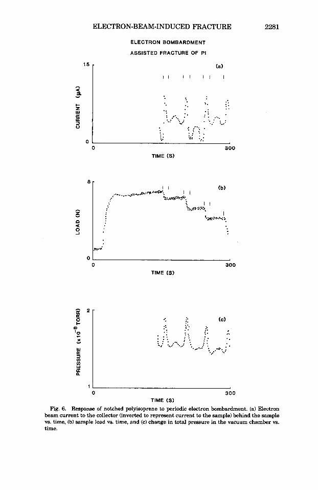
6 shows typical results, in this case for a notched PI sample, where the beam swept across the sample four times. The vertical lines indicate the times that the electron beam was hitting the sample. The small rise in pressure is exactly in synchronization with the e - beam striking the poly- mer with no indication of a "tail" in the pressure following removal of the e - beam. At high stress levels the load cell indicated a response (i.e., crack growth) within 0.1 s to the e - beam as it came onto the crack tip. This rapid response of both the load and total pressure plus the small accom- panying increase in gas pressure are not consistent with any significant heating of the polymer.
We carried out calculations of the rise in temperature due to absorption of the electron beam, following a development given by Jaegels and assum- ing a semi-infinite material with heat supplied at a constant rate over the whole surface. These calculations showed temperature increases of only 5- 8" C for the current densities and exposure times of 10 pA and 0.1 s.
ELECTRON-BEAM-INDUCED FRACTURE 2281
a 2 - K E "1
OD
Y
ELECTRON BOMBARDMENT
ASSISTED FRACTURE OF PI
(a)
o a a Y
0 0
8 -
o z
U
Y
n
s
300 TIME (S)
01 0 300
TIME (S)
w 3 v) v) w
a
a n
(C) .. .. .. 2. -.
t* * *. . . . . * : . .. ..
.. .. * .: . . . . . a : . . c.. c..: '..i *. : . ....... . ; . .......
11 0 300
TIME (S)
Response of notched polyisoprene to periodic electron bombardment. (a) Electron beam current to the collector (inverted to represent current to the sample) behind the sample vs. time, (b) sample load vs. time, and (c) change in total preasure in the vacuum chamber vs. time.
Fig. 6.
2282 DICKINSON EX' AL.
We therefore conclude from these results that the resulting crack growth is not due to an increase in the temperature of the polymer. Alternative mechanisms would involve direct bond breaking molecules in tension, yield- ing chain scission and/or crosslinking.
Similar results for BAMO/THF and IIR are shown in Figures 7 and 8, respectively. Here, in both figures, only the section of the curve when the e - beam started to sweep across the notch is shown, so that the large number of steps due to crack growth could be seen. As in the case of PI, the pressure for both BAMO/THF and IIR follows the e- beam bombardment precisely and returns to the baseline as soon as the beam is removed. The pressure rise for both BAMO/THF and IIR, when compared to PI, tended to be higher by an order of magnitude. This larger pressure rise may be attributed in part to the larger sample thickness (3 mm), i.e., more of the e- beam was hitting the elastomer surface.
To further support the argument that the small, instantaneous pressure increase observed previously was not a thermal effect, a set of experiments was done in which the notch of a weakly strained elastomer was bombarded with an e- beam of approximately 140 PA. The beam was left in the same spot for approximately 20 s before it was quickly removed. Figure 9 rep resents the typical response obtained from (a) BAMO/THF, (b) butyl rubber, and (c) polyisoprene. The two vertical arrows represent the time that the e - beam was placed on and removed from the sample, respectively. Note that when the e - beam was first moved onto the sample, a small increase in total pressure was observed which is comparable to the increase noted previously. After the e- beam had been on the sample for some time, a large increase in the total pressure is seen to occur. This increase is believed to be due to the e - beam heating the sample up to the temperature where thermal decomposition begins. As shown in Figures 9(b) and 9(c), the pres- sure decreases slowly when the e - beam is removed, owing to the slow cooling of the sample. In the case of BAMO/THF, the pressure behaves in a more complicated way. In Figure 9(a), the pressure is seen to decrease before the e - beam was removed. Also, during this large pressure burst, the sample was observed visually to flash brightly. This effect can be better seen in Figure 10, which shows the rapid increase and then decrease in total pressure, all during the time the e- beam was on the sample. The two vertical arrows indicate the times at which the e- beam was moved onto and then removed from the sample, respectively. The BAMO/THF, which is known to decompose energetically (i.e., exothermally), was apparently stimulated by the e- beam to decompose in autocatalytic fashion. The ob- served fluctuations may be due to rapid changes in surface temperature caused by the relatively violent expulsion of gases. This is similar to the effect called ablative photodecomposition proposed by Srinivasan and Mayne-Banton'j for the cooling effects of polymers decomposing under ex- posure to intense UV radiation.
The rise in pressure due to the combination of e - beam and stress also differs considerably from that produced by fracture alone. This gaseous emission accompanying fracture is known as neutral emission (NE)' and is attributed to the emission of occluded gases and/or decomposition products produced by bond breaking and thermal activation. Figure 11 shows the

ELECTRON-BEAM-INDUCED FRACTURE
1 1
A
Y z 0 a I!
O L
ELECTRON BOMBARDMENT
ASSISTED FRACTURE OF BAMO/THF
- ........
....... 2 ' 1 I .. .-...... !. I -. . ...<A. I
'*.',...
'..:. 1 I ..... :,, 1 1 ,..: ...... 1
--,-
... ....I I I. ...... I I
'7.
4.. I 1 *..,.%
.. I
l o r (a)
150 300 TIME (S)
(b)
150 300 TIME (S)
l r ( C )
CI a a 0
2283
150 300
TIME (S) Fig. 7. Response of notched BAMO/THF to periodic electron bombardment of the crack
tip. (a) Electron beam current to the colledor (inverted to represent current to the sample) vs. time, (b) sample load w. time, and (c) change in total pressure in the vacuum chamber vs. time.

2284 DICKINSON ET AL.
ELECTRON BOMBARDMENT
ASSISTED FRACTURE OF IIR
I80 TIME (S) 350
z 0 Y
a s
I
350 TIME (S)
180 TIME (S) 350 Fig. 8. Response of notched butyl rubber to periodic electron bombardment of the crack
tip. (a) Electron beam current to sample vs. time, (b) sample load w. time, and (c) change in total pressure in the vacuum chamber vs. time.
ELECTRON-BEAM-INDUCED FRACTURE 2285
TIME ( S ) 90 0
I 5.7
B a W + 0
W
3 cn cn W
a
a n I
0
a a w + I 2 0
TIME (S> 90
(C)
(b)
0 TIME (S) 90
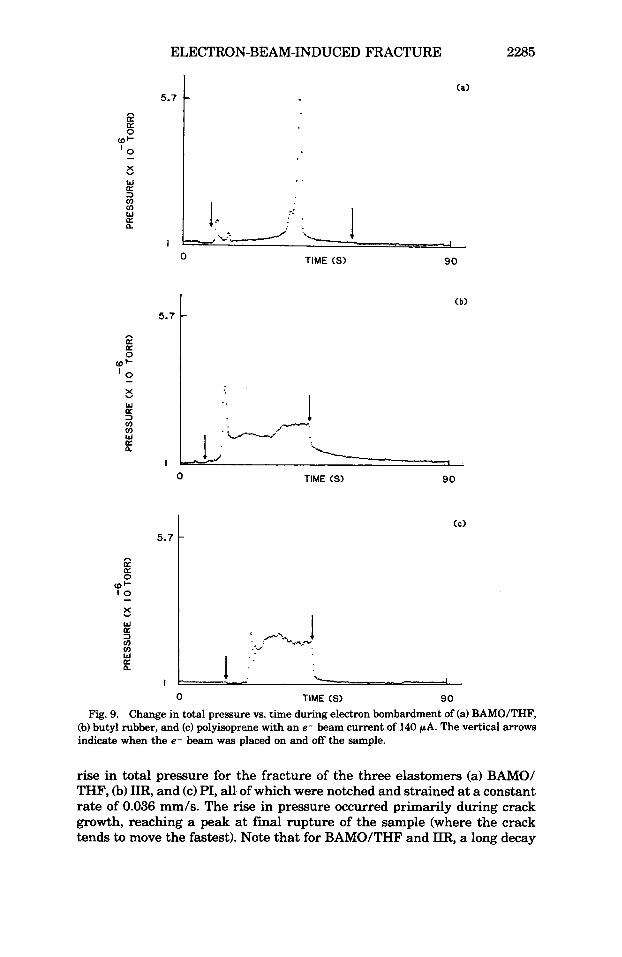
Fig. 9. Change in total pressure vs. time during electron bombardment of (a) BAMO/THF, (b) butyl rubber, and (c) polyisoprene with an e- beam current of 140 PA. The vertical arrows indicate when the e- beam was placed on and off the sample.
rise in total pressure for the fracture of the three elastomers (a) BAMO/ THF, (b) IIR, and (c) PI, all of which were notched and strained at a constant rate of 0.036 mm/s. The rise in pressure occurred primarily during crack growth, reaching a peak at final rupture of the sample (where the crack tends to move the fastest). Note that for BAMOITHF and IIR, a long decay

2286 DICKINSON ET AL.
BAMOlTHF
2.5
e a a E ‘2
(D
Y
W
3 u) u) W a
a
n.
0 I
0 5 0 100 150
TIME (S) Fig. 10. Change in total pressure w. t i e during electron bombardment of BAMOITHF
with a current of 140 PA. Arrows indicate when the e- beam was placed on and off the sample.
is observed which lasts for several tens of seconds and is completely absent in any of the pressure peaks accompanying the e--beam-induced fracture. In the case of fracture induced by stress alone, it is likely that the higher plastic work occurring at the crack tip raises the temperature sufficiently to cause diffusion and desorption of gases from the polymer. Thus the tails of the NE curves are sustained by these thermally stimulated processes and decay from the combined effects of cooling after fracture and the depletion of the available gases near the fracture surfaces. In the case of the e-- beam-induced fracture, the lack of a tail on the pressure spikes during bombardment suggests that the fracture is relatively “cool.” Although PI Fig. ll(c); note: insert is the peak and tail on an expanded time scale] shows a much shorter tail, it is still evident and can be contrasted to no tail in the case of e- beam fracture. This shorter decay time in the NE from PI may in part be due to the fact that the sample thickness is much smaller (by a factor of 31, which would result in a more rapid conduction of heat to the sample surface and thus more rapid loss of heat to the vacuum by radiation.
Another mode of e --beam-induced fracture involves the sample arrange- ment of Figure l(c), where an un-notched sample is stressed and the e- beam is allowed to strike the sample side on. Of interest here was to de- termine if the e- beam could actually penetrate through the stressed sample as a result of damage under the beam. Thus at time t = 0 the e- beam is quickly applied to the center of the elongated sample, which causes an

ELECTRON-BEAM-INDUCED FRACTURE 2287
B a cot ' 2
0
X
w 3 v) (I) W
U
a
a n
B a
10
0
- X
W
2 v) 0 W
U
a
a a
B a
12 3 a
0 I-
OD
W
3 v) v) W a n
3.4
I
<a>
TIME (S> 275 0
(C)
3.4 1
.- I .. :,
0 TIME <S> 275
Fig. 11. Change in btal pressure vs. time accompanying the fracture of (a) BAMO/THF, (b) butyl rubber, and (c) polyisoprene samples without electron bombardment. The peak in pressure for each sample was the time when complete failure occurred. The insert for PI (curve c) shows the same data on an expanded time scale (0.1 dchannel) better illustrating the observed decay.
2288 DICKINSON ET AL.
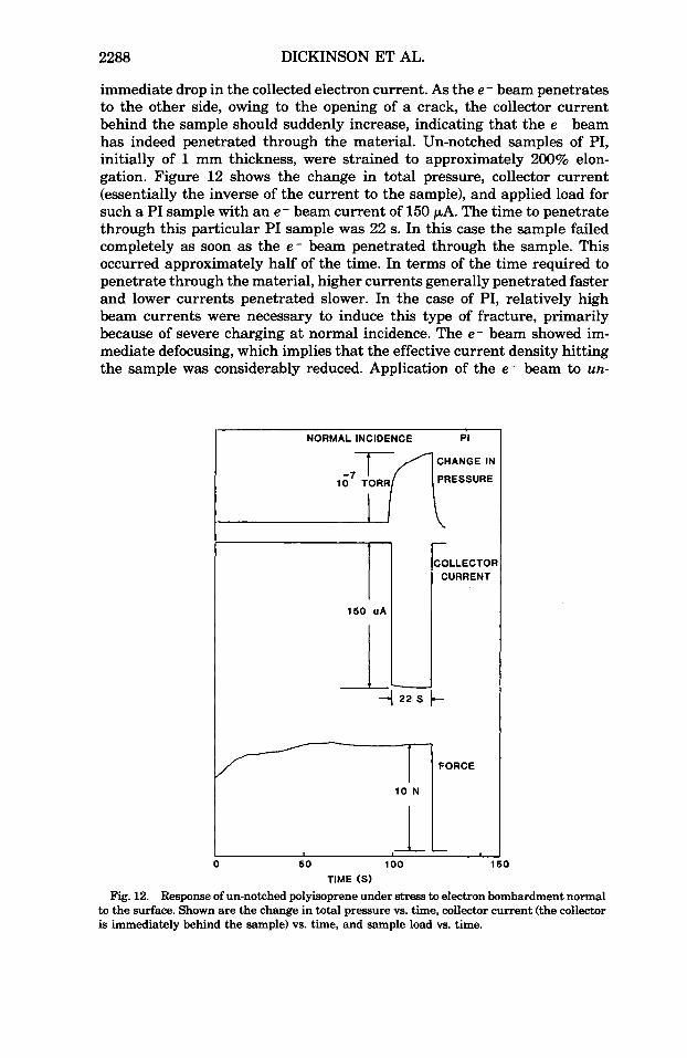
immediate drop in the collected electron current. As the e - beam penetrates to the other side, owing to the opening of a crack, the collector current behind the sample should suddenly increase, indicating that the e - beam has indeed penetrated through the material. Un-notched samples of PI, initially of 1 mm thickness, were strained to approximately 200% elon- gation. Figure 12 shows the change in total pressure, collector current (essentially the inverse of the current to the sample), and applied load for such a PI sample with an e - beam current of 150 PA. The time to penetrate through this particular PI sample was 22 s. In this case the sample failed completely as soon as the e - beam penetrated through the sample. This occurred approximately half of the time. In terms of the time required to penetrate through the material, higher currents generally penetrated faster and lower currents penetrated slower. In the case of PI, relatively high beam currents were necessary to induce this type of fracture, primarily because of severe charging at normal incidence. The e - beam showed im- mediate defocusing, which implies that the effective current density hitting the sample was considerably reduced. Application of the
NORMAL INCIDENCE Pi
CHANGE IN
PRESSURE 10 TORR
COLLECTOR CURRENT
150 u A l
- 1 22 s
10 N
0 50 l o o TIME (S)
FORCE
- 1
e - beam to un-
0
Fig. 12. Response of un-notched polyisoprene under stress to electron bombardment normal to the surface. Shown are the change in total pressure vs. time, collector current (the collector is immediately behind the sample) vs. time, and sample load vs. time.
ELECTRON-BEAM-INDUCED FRACTURE 2289
stressed samples of PI for several hundred seconds of exposure caused no noticeable damage and no penetration.
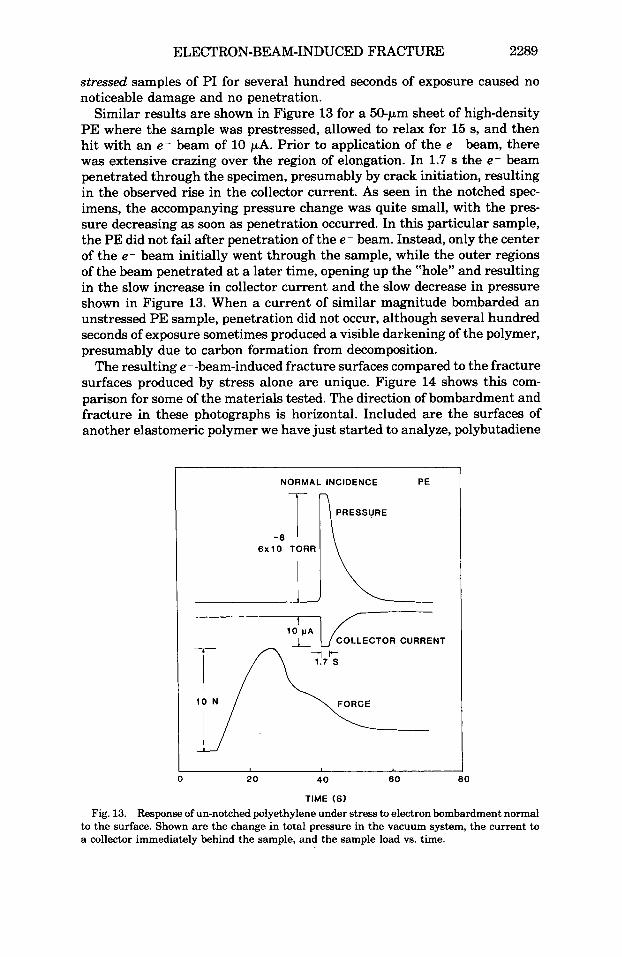
Similar results are shown in Figure 13 for a 50-pm sheet of highdensity PE where the sample was prestressed, allowed to relax for 15 s, and then hit with an e- beam of 10 pA. Prior to application of the e - beam, there was extensive crazing over the region of elongation. In 1.7 s the e- beam penetrated through the specimen, presumably by crack initiation, resulting in the observed rise in the collector current. As seen in the notched spec- imens, the accompanying pressure change was quite small, with the pres- sure decreasing as soon as penetration occurred. In this particular sample, the PE did not fail after penetration of the e - beam. Instead, only the center of the e- beam initially went through the sample, while the outer regions of the beam penetrated at a later time, opening up the “hole” and resulting in the slow increase in collector current and the slow decrease in pressure shown in Figure 13. When a current of similar magnitude bombarded an unstressed PE sample, penetration did not occur, although several hundred seconds of exposure sometimes produced a visible darkening of the polymer, presumably due to carbon formation from decomposition.
The resulting e --beam-induced fracture surfaces compared to the fracture surfaces produced by stress alone are unique. Figure 14 shows this com- parison for some of the materials tested. The direction of bombardment and fracture in these photographs is horizontal. Included are the surfaces of another elastomeric polymer we have just started to analyze, polybutadiene
NORMAL INCIDENCE PE
-8 I 6x10 TORR
10 N FORCE
0 20 4 0 6 0 80
TIME (S)
Fig. 13. Response of un-notched polyethylene under stress to electron bombardment normal to the surface. Shown are the change in total pressure in the vacuum system, the current to a collector immediately behind the sample, and the sample load vs. time.

Fig. 14. Scanning electron micrograph of fracture surfaces: (a, and a') polyisoprene without and with electron beam, (b, and b) polybutadiene without and with electron beam, (c, and c') BAMO/THF without and with electron beam, (d, and d ) butyl rubber without and with electron beam. In each bombarded sample the direction of the e- beam and fracture was horizontal.
ELECTRON-BEAM-INDUCED FRACTURE 2291
(BR). In each case significant differences in the fracture surfaces can be seen. As shown in the top three photographs, there are a large number of ridges or rows, spaced less than a micrometer apart, generally aligned parallel to the crack tip [i.e., in Fig. 16) these rows would tend to be vertical on the fracture surface]. For IIR (bottom photograph), the e -- beam-induced fracture surface does not show the same regular pattern of ridges, but still shows more structure when compared to the surface produced by stress alone.
We hypothesize that the patterns are primarily due to the material cross- linking under electron bombardment. Before the e- beam is moved onto the crack tip, the tip is in a high-stress state but still below the critical stress level for crack propagation. As soon as the beam “hits” the crack tip, the material within the e- beam penetration depth (ca. 0.1 pm) begins to undergo chain scissions and crosslinking. As bonds are broken, the re- maining loadcarrying chains experience increasing stress and eventually will fail, leading to crack propagation. At this time the crack will “jump” into the “virgin” part of the material (i.e., the part of the material where the e- beam was not able to penetrate), immediately slowing down the crack. The process will then start again provided the e- beam is still on the crack tip and if the sample is still under stress. This crack tip motion leads to a modulation of the crosslink density and thus the formation of the “bumps.”
According to Hirschfelder and Magee: the penetration depth for 1.6-keV electrons is approximately 0.1 pm, which corresponds to the observed di- mensions of the ridges. The penetration depth is dependent upon the density of the material and on the energy of the electrons; thus the dimensions of the ridges should vary among various materials, which is what we observe. From data obtained by Bopp and Sismang and by Davidson and Geib,lo it is known that for unstressed samples, IIR predominantly undergoes chain scissions under exposure to radiation, while PI and BR predominantly cross- link. Thus, according to our hypothetical mechanism, BR and PI would form the patterns when “cut” by the e- beam, while IIR would not form the “ridges,” which is what is seen in Figure 14. It would appear from the surfaces of BAMO/THF that it predominantly crosslinks under bombard- ment. The patterned surface of the e -- beam-fractured materials that cross- linked were qualitatively rigid, suggesting that crosslinking did occur, but we were not able to quantitatively measure the degree of crosslinking (the crosslinked thickness is only 1000 A, which makes any swelling or stress- strain measurements very difficult).
The ridges are very similiar to the “ductile fatigue striations” described by Pelloux,ll who attributes the patterns to plastic deformation in the crack tip and environmental cracking.
DISCUSSION The basic characteristics of electron-beam-induced fracture which we can
state at this point are the following: (i) The polymer must be elongated beyond a certain stress state to obtain
observable crack growth under bombardment. However, no evidence of crack growth occurs before the e- beam is applied; i.e., it is still below the critical stress concentration.
2292 DICKINSON ET AL.
(ii) The current densities necessary to obtain noticeable crack growth
(iii) The higher the stress, the more evident the response to the e- beam. (iv) The calculated heating effect of the e- beam on this time scale is
negligible. (v) The change in gas pressure due to evolution of gases from e- beam
bombardment of the polymer is considerably smaller compared to that obtained at higher currents and follows the e- beam current to the sample precisely with no evidence of a “cooling curve.”
(vi) Samples of un-notched PI and PE also respond to e- beam bombard- ment when stressed.
(vii) The fracture surfaces show features (ridges/rows or “bumps”) for the e --beam-induced fracture that are completely missing from the unbom- barded fracture surface.
These results suggest that the phenomenon of e --beam induced fracture is not dominated by thermal effects, but instead appears to be a direct consequence of electronic interaction, i.e., direct scissions of load-bearing molecular chains by these electron collisions. These scissions result in more strain of the remaining chains, thus causing crack growth.
A lO-pA, 1.6-keV electron beam left on a sample for 0.1 s will deposit approximately 240 Mrads into a volume estimated to be 7 x cm3 by assuming the value of 0.1 pm for the electron penetration range found by Hirschfelder and Magee.a If we assume a G factor of 0.64 for main-cahin bond scission and a G factor of 2 for crosslinking for a typical elastorner,’2 then according to Charlesby13 the number-average molecular weight be- tween crosslinks M, and between scissions M, will be
below critical stress levels were on the order of 100 pA/cm2.
M, = 0.48 x 10⁶/G,r = 1000
M, = 0.96 x 10⁶/G,r = 6250
where r is the dose in megarads. Thus such a material would predominantly crosslink, although it should be remembered that bond breaking is the initial event, even for crosslinking. At zero stress the electron-induced scis- sions tend to react quickly to reform the original bond or produce a crosslink. However, when the load-bearing chains in the crack tip region are under stress, electron-induced bond scissions would tend to lead to the separation of the newly created chain ends, thereby partially suppressing reattachment and favoring crack growth. This is consistent with the observations that a minimum stress is required for the effect of the e- beam to be clearly noticeable and that e - beam fracture appears to be a *‘cool’’ process, similar to ablative photodecomposition.6
Although the work reported here should be regarded as tentative, the prospect of performing controlled direct rupture of bonds appears promising and should lead to improved understanding of fracture in elastomers and polymeric materials. Furthermore, the unique type of fracture surfaces due to combinations of stress and electron bombardment may lead to practical applications, e.g., preparation of surfaces for adhesive bonding. Finally, let us mention that we are currently investigating the e --beam-induced frac- ture of single fibers of glasses and polymers and seeing similar and inter- esting results.

ELECTRON-BEAM-INDUCED FRACTURE 2293
The authors would like to thank H. M. Leeper, Alza Corporation, for providing the PI samples; Y. Gupta and P. Majewski, Washington State University, for providing the BAMO/ THF samples; and A. N. Gent, University of Akron Institute of Polymer Science, for the BR samples and for helpful discussions. This work was supported by the Office of Naval Research, Contract N00014-80-GO213, NR 659-803, Sandia National Laboratories, and NASA-Ames Re- search Center Interchange No. NCA24R840-202.
References 1. E. H. Andrews, in Polymer Science, A.D. Jenkins, ed., Elsevier, New York, 1972, Vol.1,
2. A. N. Gent, in Science and Techmbgy of Rubber, F. R. Eirich, ed., Academic, New York,
3. R. S. Rivlin and A. G. Thomas, J. Polym. Sci., 10, 291 (1953). 4. A. G. Thomas, J. Polym. Sci., 18, 177 (1955). 5. J. C. Jaeger, Aust. J. Sci. Res., 5, 1 (1952). 6. R. Srinivasan and V. Mayne-Banton, Appl. Phys. Lett., 41, 576 (1982). 7. L. A. Larson, J. T. Dickinson, P. F. Braunlich, and D. B. Snyder, J. Vw. Sci. Technol.,
8. J . 0. Hirschfelder and J. L. Magee, Phys. Reu., 73, 207 (1948). 9. C. D. Bopp and 0. Sisman, Nucleonics, 13, 28 (1955).
10. W. L. Davidson and J. G. Geib, J. Appl. Phys., 19, 422 (1948). 11. R. M. N. Pelloux, ASM Trans., 62, 281 (1969). 12. D. T. Turner, Polymer, 1, 27 (1960). 13. A. Charlesby, Atomic Radiation and Polymers, Pergamon, New York, 1960, Chaps. 9,
Chap. 9.
1978, Chap. 10.
16, 590 (1984).
10.
Received November 19, 1984 Accepted April 8, 1985