Embed Size (px)
Citation preview

ESCUELA TÉCNICA SUPERIOR DE INGENIERÍA (ICAI)
ELECTROMECHANICAL ENGINEERING DEGREE
Mechanics field
CRANE’S DESIGN AND MANUFACTURING
PROCESS
Author: Loreto Rodríguez-Campra Hermoso
Director: Michal Vašíček
Madrid
June 2018


ESCUELA TÉCNICA SUPERIOR DE INGENIERÍA (ICAI)
ELECTROMECHANICAL ENGINEERING DEGREE
Mechanics field
CRANE’S DESIGN AND MANUFACTURING
PROCESS
Author: Loreto Rodríguez-Campra Hermoso
Director: Michal Vašíček
Madrid
June 2018


CRANE’S DESIGN AND MANUFACTURING PROCESS
Autor: Rodríguez-Campra Hermoso, Loreto
Director: Vašíček, Michal
Entidad Colaboradora: ICAI - Universidad Pontificia Comillas
El equipo de Formula Student de la Czech Technical University de Praga necesita
transportar el coche de carreras con el que competirá en la competición Formula SAE.
El transporte se realiza mediante un camión que ya tienen. El problema es que no
pueden simplemente meter el coche dentro del camión. Normalmente bastaría con una
rampa para empujarlo al interior, pero la parte baja del coche está demasiado cerca del
suelo y rozaría.
Este Trabajo Fin de Grado consiste en el diseño de una estructura con el objetivo de
poner el coche del CTU Cartech (el quipo) dentro del camión. Cubrirá el diseño del
marco de aluminio que soportará el peso del coche, la optimización del mismo mediante
análisis con el programa CATIA V5 y la fabricación del mismo. Además, será necesario
buscar un gancho del que poder colgar el coche y las vigas telescópicas que soportarán
la estructura.
Por otro lado, también hace un recorrido por los pasos a seguir cuando se crea un
producto. Primero, ha de identificarse una necesidad o un problema. Después, se
discuten las posibles soluciones y se decide cuál es la más apropiada teniendo en cuenta
las circunstancias. En este punto, se pasa a la optimización de la solución, y finalmente,
la fabricación y producción.
En este Proyecto, no sólo tiene importancia el trabajo técnico, el estudio y el diseño,
sino también el hecho de que gracias al proceso por el que se llegó al TFG y su
realización han permitido el desarrollo de la capacidad de diseñar un producto conforme
a las necesidades concretas de un grupo de personas, además de habilidades personales
y comunicativas tan necesarias en un ingeniero.

CRANE’S DESIGN AND MANUFACTURING PROCESS
Author: Rodríguez-Campra Hermoso, Loreto
Director: Vašíček, Michal
Collaborating Entity: ICAI - Universidad Pontificia Comillas
The Formula Student team of the Czech Technical University in Prague needs to
transport their racing car, the one which competes in the SAE competition. This
transportation is made in a trailer that they already have. The problem is that they do not
have a way of putting the car inside. The most logical solution would be a slope, but the
bottom of the car is just too low.
This Bachelor Thesis consist of the design of a crane which objective is to put the CTU
Cartech’s car inside the trailer that will carry it. It is going to go through the design of
the aluminum frame that will lift the car, the optimization of that frame, as well as its
manufacturing. Moreover, it will also be necessary to find the hook which will be used
to lift the car and the telescopic legs that support the frame.
Besides, it goes all the way through the production of any product. First, a necessity has
to be found. Then, we have to reach and discuss which solution is better. Later, this
solution has to be studied and optimize. Finally, it has to be produced.
In this project, what is important is not only the design and technical work done, but
also the fact that the author had the change to apply the theoretical knowledge she has
acquired during her degree in the design and proposal of production of the device and
the events that drove her to ending doing this bachelor thesis and the production of it
has given the author the opportunity to test herself on another fundamental engineering
skills as the ability of convincing that a project is valuable or the ability of working in a
team and fulfill the necessities of others.

Index of Documents
DOCUMENT I. REPORT Part I. Report
pages 9
a
40
31 pages
Parte II. Datasheets pages 41 a 46 5 pages
DOCUMENT II. DRAWINGS
1. List of drawings page 3 1 page 2. Drawings pages 5 a 8 4 pages

CRANE’S DESIGN AND MANUFACTURING PROJECT
Loreto Rodríguez-Campra Hermoso
IV

CRANE’S DESIGN AND MANUFACTURING PROCESS
Loreto Rodríguez-Campra Hermoso
V
Synopsis
The Formula Student team of the Czech Technical University in Prague needs to
transport their racing car, the one which competes in the SAE competition. This transportation
is made in a trailer that they already have. The problem is that they do not have a way of putting
the car inside. The most logical solution would be a slope, but the bottom of the car is just too
low.
Apparently, this Bachelor Thesis just consist of the design of a crane which objective is
to put the CTU Cartech’s car inside the trailer that will carry it. It is going to go through the
design of the aluminum frame that will lift the car, the optimization of that frame, as well as its
manufacturing. Moreover, it will also be necessary to find the hook which will be used to lift
the car and the telescopic legs that support the frame.
Besides, it goes all the way through the production of any product. First, a necessity has
to be found. Then, we have to reach and discuss which solution is better. Later, this solution
has to be studied and optimize. Finally, it has to be produced.
The point it is not that this problem existed and the author designed a solution. The point
is: how did the author know that the team had this problem? Why is a Spanish Erasmus student
giving an answer to a glitch of a Czech Formula Student team?
The author had the change to apply the theoretical knowledge she has acquired during
her degree in the design and proposal of production of the device, but the events that drove her
to ending doing this bachelor thesis and the production of it has given the author the opportunity
to test herself on another fundamental engineering skills as the ability of convincing that a
project is valuable or the ability of working in a team and fulfill the necessities of others.
This is really important because all of us engineers study the same, but it is working on
something where we really learn.

CRANE’S DESIGN AND MANUFACTURING PROCESS
Loreto Rodríguez-Campra Hermoso
VI
SYNOPSIS

CRANE’S DESIGN AND MANUFACTURING PROCESS
Loreto Rodríguez-Campra Hermoso
VII
Abstract
Formula SAE is a worldwide student competition where the target is to create the best
racing car prototipe. Each university has its own team. CTU cartech is the team of the Czech
Technical University in Prague and this bachelor thesis is essentially a colaboration with this
project. It consist of the design and manufacturing process of a crane with the objective of
placing the racing car into the trailer that is going to be used for its transportation. But how do
actual motor-racing teams manage to transport their cars? And can we apply these technics or
should we come up with an original solution?
Key words: crane, structure, design, teamwork, Formula Student SAE.
.


In the middle of difficulty
lies opportunity.
ALBERT EINSTEIN
It always seems impossible
until it’s done.
NELSON MANDELA


Acknowledgments
Loreto Rodríguez-Campra Hermoso
First of all, thanks to the mix of unexpected circumstances that ended in me doing an
Erasmus exchange year in Prague.
Second, warm thanks to the Formula Student team, the CTU cartech. They suggested
me the topic of my bachelor thesis and let me work with them. Specially, I have to thank Lukas,
the team captain, who has helped me with all the problems I was having in using a new program
or designing the suitable crane. I am very grateful for their trust in my work.
Of course, thank you very much to Michal Vasicek, the director of this thesis, for his
patience and guidance. Thank you for accepting to guide me in this bachelor thesis and being
so easy-going, not only with all the bureaucratic problems that we have had, but also with the
difficulties I have had with the project itself.
Then, thank you to Alberto of the ICAI International Office, Damian and Juan Norverto,
the coordinator of the Bachelor Thesis in ICAI, who have been so understanding with our
situation in the Czech Technical University and has helped as much as they could. Also, thank
you to all the ICAI professors, without them I would not have the knowledge to develop this
bachelor thesis.
Thank you very much to my family who has listened my problems and supported me in
each crossroads.
Last but not least, a heartfelt thanks to Marta, my lovely roommate who has beared me
the hole year, my Erasmus friends: Elia, Marta, Edu and company, Nacho, Danilo, Maxime,
Manuela, Alba, the argentinian and the mexican crew, and the rest of friends that have made
this a wonderful year in Prague, where I have grown much more than I could have ever imagined
thanks to them. Also I have to name Rafa, my helpmate this year, the other ICAI student in
Prague with whom I have solved every problem.
Thank you for making this Bachelor Thesis the reminder of a once in a lifetime
experience.
CRANE’S DESIGN AND MANUFACTURING PROCESS IX

Loreto Rodríguez-Campra Hermoso
ACKNOWLEDGMENTS
CRANE’S DESIGN AND MANUFACTURING PROCESS X

DOCUMENT I
REPORT

2 CRANE’S DESIGN AND MANUFACTURING PROCESS
Loreto Rodríguez-Campra Hermoso
DOCUMENT I. REPORT INDEX

3 CRANE’S DESIGN AND MANUFACTURING PROCESS
Loreto Rodríguez-Campra Hermoso
Index
I. Report 9
1. First steps 11
1.1. State of art .................................................................................................................. 11
1.2. Incentives .................................................................................................................. 14
1.3. Bachelor Thesis’ Objective ........................................................................................ 16
1.4. Working Methodology ............................................................................................... 16
1.5. Resources used ........................................................................................................... 16
2. Design 17
2.1. Problem ...................................................................................................................... 17
2.2. Racing Car ........................................................................................................................... 18
2.3. Trailer ........................................................................................................................ 18
2.4. Designing process ...................................................................................................... 18
2.4.1. First Approach ..................................................................................................... 19
2.4.2. First Design ......................................................................................................... 19
2.4.3. Evolution of the Design ....................................................................................... 20
2.5. Final Design ............................................................................................................... 22
3. Analysis 25
3.1. Frame Analysis .......................................................................................................... 25
3.2. Telescopic Legs Analysis .......................................................................................... 29
3.3. Support Beams Analysis ............................................................................................ 30
4. Manufacture Proposal 33
4.1. Circumstances ………………………………………………………………………33
4.2. Assembly ................................................................................................................... 34
4.3. Manufacture Proposal ................................................................................................ 35
4.4. Final Manufacturing Method ..................................................................................... 36
Bibliography 37
II. Datasheets 39
ALUPA Beams Profiles 41
Scheppach Hook CB 01 42
B44 – Dm Koleek Wheels 43
Iglidur Tribo - Tape 44


4 CRANE’S DESIGN AND MANUFACTURING PROCESS
Loreto Rodríguez-Campra Hermoso
DOCUMENT I. REPORT- FIGURES
Index of figures
1. Figure 19. Transportation truck of a F1 car, pinterest. .............................................................. 13
2. Figure 20. Modern transportation of a F1 car, [5]. .................................................................... 13
3. Figure 24. Car W196 and Mercedes Renntransporter, [7]. ................................................ 14
4. Figure 1. Version FS.09 of the CTU Formula Student car ........................................................ 18
5. Figure 2. Surfaces of FS.10 car, CATIA V5 ............................................................................ 19
6. Figure 3. Trailer model, CATIA V5 ........................................................................................ 19
7. Figure 4. First design sketch. .................................................................................................. 21
8. Figure 5. First structure model, CATIA V5. ............................................................................ 22
9. Figure 6. Assembly of the first structure and trailer model, CATIA V5 ..................................... 22
10. Figures 7 and 8. Rectangular profiles, [3]. ............................................................................... 23
11. Figure 9. Final frame model, CATIA V5 ................................................................................. 23
12. Figure 10. Telescopic legs model and detail, CATIA V5. ......................................................... 24

5 CRANE’S DESIGN AND MANUFACTURING PROCESS
Loreto Rodríguez-Campra Hermoso
13. Figure 11. Analysis first frame model, CATIA V5 ................................................................... 28
14. Figures 12. Analysis second frame model, CATIA V5. ............................................................ 29
15. Figure 13. Analysis second frame model, CATIA V5............................................................... 29
16. Figure 14. Displacement analysis final frame model, CATIA V5.. ............................................ 30
17. Figure 15. Von Mises stress analysis final frame model, CATIA V5. ........................................ 30
18. Figure 22. Elastic band sketch. .......................................................................................... 31
19. Figure 16. Von Mises stress analysis telescopic leg, CATIA V5 ............................................... 32
20. Figure 17. Von Mises stress analysis rail beam, CATIA V5.. .................................................... 32
21. Figure 18. Von Mises stress analysis upper support beam, CATIA V5.. .................................... 33
22. Figure 21. Crane final design sketch.. ..................................................................................... 35
23. Figure 23. Support Beams sketch. ........................................................................................... 36

7 CRANE’S DESIGN AND MANUFACTURING PROCESS
Loreto Rodríguez-Campra Hermoso
DOCUMENT I. REPORT - ACRONYMS
Acronyms
ICAI Instituto Católico de Artes e Industrias
PFC Proyecto Fin de Carrera
CTU Czech Technical University
ČVUT České Vysoké Učení Technické v Praze
CAD Computer-Aided Design
CAE Computer-Aided Engineering
CATIA Computer-Aided Three dimensional Interactive Application
FEM Finite Element Method
GTAW Gas Tungsten-Arc Welding
TIG Tungsten Inert Gas
GMAW Gas Metal Arc Welding
MIG Metal Inert Gas

8
10
CRANE’S DESIGN AND MANUFACTURING PROCESS
Loreto Rodríguez-Campra Hermoso

PART I
REPORT

P a g e 10 | 1
CRANE’S DESIGN AND MANUFACTURING PROCESS
Loreto Rodríguez-Campra Hermoso

P a g e 11 | 1
CRANE’S DESIGN AND MANUFACTURING PROCESS
Loreto Rodríguez-Campra Hermoso
First steps
This Bachelor Thesis consist of the design of a crane which objective is to put a Formula
Student’s car inside the trailer that will carry it. It goes all the way through the production of
any product. First, a necessity has to be found. Then, we have to reach and discuss which
solution is better. Later, this solution has to be studied and optimize. Finally, it has to be
produced.
It is going to go through the design of the aluminium frame that will lift the car, the
optimization of that frame, as well as it’s manufacturing. Moreover, it will also be necessary
to find the hook which will be used to lift the car and the telescopic legs that support the frame.
1.1. State of the art
Engineering has been described by the Engineers Council for Professional Development
in the United States as the “creative application of scientific principles to design or develop
structures, machines, apparatus or manufacturing processes, or works utilizing them singly or
in combination”.
But engineering is not only this, engineering is as ancient as time. Even in the stone age,
people used their ingenuity to manufacture tools made out of the resources they had available:
stones, branches, leather… They put things together like in a jigsaw puzzle. They created their
own jigsaw puzzles to fulfil their needs. This is the essence of engineering, the capacity of
look into the problems and create a way of tearing them up.
Besides, they share their knowledge field with scientist, but they are different. The
scientist’s objective is to know, while the engineers’ is to do. While the scientists study the
physical world, the engineer applies this knowledge to solve practical problems. These
problems cannot be pre-selected, the engineer must solve them as they arise, trying to satisfy
conflicting requirements. The solution given should be the most desirable one, taking all the
factors into account. Of course, engineers’ work is much easier thanks to the knowledge
provided by scientists, ones’ work is better with the others’ and viceversa.

P a g e 12 | 1
CRANE’S DESIGN AND MANUFACTURING PROCESS
Loreto Rodríguez-Campra Hermoso
Problem solving is common to all engineering work [1]. Either if it requires mathematical
calculus or common sense, if it is physical or economic, the most important matter is the
process of creative synthesis and design, the way the engineer looks at the glitch in order to
crack it in the most optimum and original way.
In ancient times, engineers, craftsmen and artists had the same goal, but they mainly
proceeded by trial and error. Yet by combining fiddling with imagination they were able to
create brilliant devices. In fact, the word “engineer” derives from the latin word ingenium,
which means trick, a clever or special way of doing something. Nowadays there are many
more resources and much more acquired knowledge, but it is very important to keep in mind
the perspective. As long as the theoretical knowledge is basic and necessary, it is the way that
you use it what makes the difference. A great engineer is not the one who knows everything,
but the one who applies that knowledge in the best way.
For example, the romans are known for their outstanding engineering constructions. They
built bridges, roads, tunnels and impressive aqueducts. These feats are a proof of their
impressive engineering skills and ingenuity. Roman engineers took older ideas and inventions,
improved them and innovate. New materials and techniques were developed, they led a
revolution in the construction of bridges and aqueducts, they refined the existing weapons at
the same time that they controlled the power of water. These engineering achievements
produced wealth and prosperity, improving the roman standard of living and helping to
maintain the dominance of Rome in Europe and the Mediterranean. [4]
This is a illustrative example of the function on an engineer and the magnitude of its work,
but most crucial is to realize the importance of thinking out of the box. Engineers study a
whole heap, they learn about mechanics, mathematics, physics, electricity… and during the
process it is very important to learn how to mix those fields and use them to improve society
and people’s lives.
The problems an engineer has to solve vary in scale, difficulty and subject, but the steps
that should be followed are the same. First, the situation should be analysed, and a plan of
attack studied. In this way, the problem is reduced to a question which has to be answered. By
reasoning from known principles or by other more imaginative means and methods, the
question is answered, and a new design approached. This answer or design must always be
checked, so the accuracy and adequacy of the solution to the original problem can be assured.
Finally, the results should be clarified and reported in a suitable form.
However, as well as the principal function of an engineer is to solve problems, the whole
process is important. First, an engineer should be able to detect problems, to know how to
analyse what is happening. Second, is essential to listen at the people affected (considering it
is not just a technical reparation) because maybe the ideal solution for you is not what they
really need, so the engineer should be able to empathize and walk in their shoes. And finally,
the solution should be executed or constructed, because having an idea is good, but it is useless
if it is not brought to reality.

P a g e 13 | 1
CRANE’S DESIGN AND MANUFACTURING PROCESS
Loreto Rodríguez-Campra Hermoso
For this reason, there are all kinds of engineers each one specialist in their own field of
knowledge. These fields of knowledge can be divided by the specific topic that they study:
aerospace engineering, civil engineering, electrical engineering, mechanical engineering,
software engineering… but they can also be divided by the part of the solving problems’
process they work into. All of these engineers are as relevant as the others, because they need
each other’s work to succeed in their own. As it was said before, it is not only important to
have the idea of how an issue can be solved, but also to set it in motion.
This bachelor thesis is not only a design of a crane and a suggestion of the manufacturing
process. It is a way of putting in practice everything that was said here before. In fact it would
not have been possible if all the steps hadn’t been followed.
The topic of this bachelor thesis wasn’t chosen because the author has special interest in
cranes or structures, but because it was the problem that had to be solved. The CTU cartech
team had the problem of putting their car into their trailer, and when I asked what topic can I
choose so I can also help you, they told me this issue. Moreover, they are building the proposed
solution at this instant, so it is not only an ideal solution, but an actual reality.
To start laying some options on the table, I looked at precedents of this problem, how do
actual motor-racing teams manage to transport their cars?
Figure 19. Transportation truck of a F1 car, pinterest.
Figure 20. Modern transportation of a F1 car, [5].

P a g e 14 | 1
CRANE’S DESIGN AND MANUFACTURING PROCESS
Loreto Rodríguez-Campra Hermoso
Nowadays the transportation process is complex, long and it has to be carried out very
carefully, paying attention to the details. Nine days before the race they start moving and
packing components. The cars travel disassembled in wood containers, without spoilers and
the rest of sensitive components that are packed independently. [5]
In the times when the Formula 1 was less advanced in technology, had less followers and
less financial aids, the transportation system was more unsophisticated. The racing cars were
transported in a trailer and the most common way of putting the car into it was using a slope,
as it can be seen in Figure 19.
This last example is the one that applies more to our case, due to the CTU cartech budget
and available resources. We seek for a simple and economic solution, so inspiration is more
likely to be found in the way they transported the cars before, not now.
Figure 20. Car W196 and Mercedes Renntransporter, [7].
1.2. Incentives
Last September, I arrived at Prague to do an one-year exchange in the Czech Technical
University. I was excited and scared about the year that was about to start and the only thing
I was able to think was: “I have to make the most of this year, I will not have the opportunity
to live this experience again.”
Having this feeling I arrived at the mechanical faculty (fakulta strojní), which happened
to be my host faculty. The first thing I saw there were four Formula Student cars, exhibited
as they were the best trophy. For the last two years, one of my main aspirations was to enter
the ICAI Speed Club, but never had enough time. I was never entirely sure I wanted to join
the club, as I am far from being an expert in motorbikes.
However, this all changed when I saw these racing cars. I felt this would be my last
chance to accomplish my goal, and it had to be here, in Prague. It is ironic because I decided
to take a step forward in the most unlikely situation: in a foreign country, the last year of my
degree, in a university that I do not know and where the language spoken is no other but
Czech.

P a g e 15 | 1
CRANE’S DESIGN AND MANUFACTURING PROCESS
Loreto Rodríguez-Campra Hermoso
But despite this, I was determined to join the team, it was my main purpose, although I
knew it wouldn’t be easy. So, I started looking for the team captain (Lukas) and getting in
touch with the teachers.
Before entering the team, I had to do a task: to model a meat meal in the CAD program
CATIA V5. Nevertheless, the only problem was that the instructions were in Czech and I had
never used this program before, but despite all of it I managed to finally do it.
Little by little, what only was an objective (entering the team) became my passion. So,
I decided to make the perfect duo; on one hand I would be doing my bachelor thesis and on
the other hand I would be helping the people who I was working with by facing real problems
and doing not only theorical projects but also practical ones.
Once I decided that, I got in touch with Lukas and the rest of the team. I realised that it
was the perfect task for me, and their need to solve a problem ended being my bachelor thesis
topic: ‘the design and manufacturing process of a crane to lift the racing car and put it into
the trailer used for its transportation’. But, what is it mainly about?
The Formula Student’s team of the ČVUT (Czech Technical University) needed a way
to put their competition car into the trailer that is going to be used to transport it. Until now,
they could not use a slope because the bottom of the car is too close to the floor, so they had
to lift the car by themselves and put it in the trailer. Furthermore, they had to take out the
shock absorbers because they could be damaged in the transportation.
Imagine having to do this every time you have to transport the car anywhere. This
problem is not only annoying for the people in the team, but also it is a waste of time.
Furthermore, the shock absorbers and some other parts are very likely to be damaged in this
procedure.
For these reasons, this structure should be done: to save time, efforts and avoid the
breaking of the car’s components. I was so glad that they trusted me for this, even if it is not
a task as relevant as others.
At this point the only thing left to do was to find a supervisor for the Bachelor Thesis
here, in the CTU of Prague. It was not so evident who to talk with, because of three facts:
first, I had a very specific topic; second, I was an Erasmus student in Prague; and at least but
not less, not every professor is interested in guiding a student that they would only know for
several months. So, I was inclined to begin the search by speaking with the professors that I
thought would be more interested in that field: the department of Automotive, Combustion
engine and Railway engineering. So, I emailed the head of the department.
When everything seemed to be all right, I received the answer to the email sent. It was
a polite way of telling me that they did not work with Erasmus and if they do, they will be
really strict with me. At first, I was confused, but later I realised that was the perfect
opportunity to develop my communicative and persuasive skills. As Albert Einstein said:
‘Aptitude is made of 1% of talent and 99% of work.’. So I met with him. After an hour talking
about my bachelor thesis, he accepted looking for a tutor for me. That is how Michal Vasicek
ended up being this project director.

P a g e 16 | 1
CRANE’S DESIGN AND MANUFACTURING PROCESS
Loreto Rodríguez-Campra Hermoso
In conclusion, this bachelor thesis has brought me the opportunity not only to design and
produce a crane but also to develop personal and intellectual skills. Moreover, the essence of
this project is what is behind, what developing a project means: being part of a team, working
in group, but also alone, facing difficulties, following instructions, being creative, being an
engineer.
1.3. Bachelor Thesis’ Objective
The object of study of this bachelor thesis is a crane, specifically designed for the car and
trailer of the CTU’s Formula Student team.
Its objective is, beyond covering a necessity, to go through all the steps of the production
of a product, in this case a crane. From the conception of the product in response to a problem,
to the manufacturing.
Specifically, it will cover the conceptualization of the idea, the design of the crane, the
optimization of it and its production.
1.4. Working methodology
The steps followed for the realization of this thesis were:
1. Identify and recognise a necessity (lift and put the car into the trailer).
2. Discuss possible options and seek the best one.
3. Decide the specific solution of the problem
(the crane: support structure with a hook to lift the car).
4. Design the structure.
5. Optimize the structure’s model (CATIA V5 and structure analysis)
6. Design the telescopic legs which will support the frame.
7. Search for the rest of the elements of the crane: wheels and hook.
8. Production: build the structure and attach it to the trailer.
1.5. Resources used
❖ CATIA V5
❖ Knowledge of structural analysis and strength of materials
❖ Formula Student team’s experience

P a g e 17 | 1
CRANE’S DESIGN AND MANUFACTURING PROCESS
Loreto Rodríguez-Campra Hermoso
Chapter 2
Design
This chapter will go through all the designing process of the crane, the problem that was
intended to be solved and the process of the creation of a solution.
2.1. Problem
Every engineering design responds to a necessity or a handicap that you need to get rid of.
In this case, the problem was the transportation of the CTU Formula Student’s car, most
specifically, the way of putting the car inside the track that carries it from one place to another.
Figure 1. Version FS.09 of the CTU Formula Student car
In the designing of their new racing car, the FS.10, the Formula Student’s team had the
objective of decreasing the center of gravity. In order to achieve it, they designed a new frame
and monocoque to be able to put the engine lower. Moreover, they adjusted the pilot’s position
and designed a new tank. The new tank is really low, in fact the space between the car and the
floor is actually 45 mm.
This means that it is not possible to use a ramp or slope to put the car into the trailer because
it would have to be very long, and the trailer is not big enough to carry the car and the slope.
For this reason, the only way they had to do it was lifting the two tones car by themselves.

P a g e 18 | 1
CRANE’S DESIGN AND MANUFACTURING PROCESS
Loreto Rodríguez-Campra Hermoso
2.2. Racing car
The new model’s dimensions that are
needed for the design are:
• Length: 2’93 m
• Width: 1’5 m
• Height: 1’2 m
It weights 200 kilograms.
Figure 2. Surfaces of FS.10 car, CATIA V5
2.3. The trailer
The trailer that it is going to be used to
transport this car is the one modelled in
Figure 3. Its dimensions are:
• Ceiling-floor: 1’475 m
• Length: 3 m
• Width:1’5 m
The width has been measured taking in
account the reinforces. The previous
measure is the minimum width. Figure 3. Trailer model, CATIA
V5
2.4. Designing process
During the designing process, the most important thing was to adecuate the possible
solutions to the circumstances of the problem and the situation. So the final design is the result
of theoretical knowledge, previous experience of the team, budget and communication
between the people involved.

P a g e 19 | 1
CRANE’S DESIGN AND MANUFACTURING PROCESS
Loreto Rodríguez-Campra Hermoso
2.4.1. First approach
The first step in the designing process should always be listening and be concious of
what is the purpose of the device, what are the limitations of the design, but the most
important thing is being aware of what do the people who are going to use it think.
The purpose has been explained above with detail (2.1. Problem).
The limitations are time, the budget, available resources and the fact that the team is
made of engineering students not specialists.
Speaking about time, we had to have the final design in May, because in summer the
races and the competition begin, so the device has to be installed and manufactured by
this moment. This fact is relevant because it forces us to do a simple design, so it can be
affordably to manufacture it in that time by one mechanical engineering student.
Speaking about the budget, it is also a relevant issue, due to the fact that in the
Formula SAE competition (were the team participates and the car races) the marketing
and business plan are taken in account.
Moreover, the available resources are the ones that the team is able to adquire by
itself, buying it in stores that are able to deliver their products to us. So this limites the
resources to the ones that can be found in Prague.
Last, but not less important, there is the fact that the designer, the author of this
bachelor thesis, is a fourth year degree student of electromechanical engineering, the
team captain, Lukáš Pakoň, is a master student of mechanical engineering and so is the
one who is going to manufacture the device and put all the pieces together.
This considerations are very important, because as it was said before, engineering
designs are a way of using our knowledge in an useful, suitable and original way.
2.4.2. First design
First, there was a meeting where the team made clear what they needed and how they
needed the device. There was an inicial brainstorming where many ideas came up.
Looking at all of them, the team said which one was more desirable for them, and the
chosen structure was Figure 4.

P a g e 20 | 1
CRANE’S DESIGN AND MANUFACTURING PROCESS
Loreto Rodríguez-Campra Hermoso
Figure 4. First design sketch.
The reasons of choosing this design were:
1. First, the device should be built into the trailer.
2. The principal structure has to be at the upper part of the trailer, because it is
where there is more available space. Moreover, the most suitable way of
lifting the car is to hang it with a hook from the chasis. The car would be
hung from the curve part of the chasis that is above of the driver’s head.
3. Third, it is easy to adquire the parts of this design and feasible to
manufacture.
In operation, the car would be hung by the hook. Then, an elastic band will be used to
avoid that the front part of the car swings. At last, the only thing left to do is push the
structure into the trailer. The upper beams would be telescopic, by putting the principal
beam into a bigger one attached to the trailer’s ceiling. The legs with wheels would also
be telescopic, so we are able to make them smaller and put them into the trailer as well.
2.4.3. Evolution of the design
Once the requirements were settled and what they needed was clear, the next step was
studing if this structure was technically possible and improving it by making use of
structures and strenght of materials’ knowledge, along with the advice of university
professors, .
The first mistake that had to be amended was the upper supporting beams, the cross
between the two upper beams. The structure had to be pushed into the trailer and this is
possible if the upper beams slide into two bigger beams attached to the trailer, but the
cross-beams welded to the ones in the sides do not allow this to happen. For this reason,
another support had to be found. It should be connected to the upper beams, but in a way
that they could slide freely into the other ones.
P a g e 21 | 1
CRANE’S DESIGN AND MANUFACTURING PROCESS
Loreto Rodríguez-Campra Hermoso
Moreover, this cross protected the structure from bending if for example, the wind had
blown wildly from one side to another of the structure with the car hanging from it.
To do both, solve the slidding problem and
prevent the bending moment to curve the
structure, instead of the cross-beams, there would
be two others in the lateral part welded in the front
part of the upper beam and in another parallel one.
This last one would be supported by a rail attached
to the trailer (Figure 5).
Figure 5. First structure model, CATIA V5
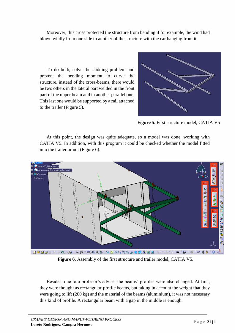
At this point, the design was quite adequate, so a model was done, working with
CATIA V5. In addition, with this program it could be checked whether the model fitted
into the trailer or not (Figure 6).
Figure 6. Assembly of the first structure and trailer model, CATIA V5.
Besides, due to a profesor’s advise, the beams’ profiles were also changed. At first,
they were thought as rectangular-profile beams, but taking in account the weight that they
were going to lift (200 kg) and the material of the beams (aluminium), it was not necessary
this kind of profile. A rectangular beam with a gap in the middle is enough.

P a g e 22 | 1
CRANE’S DESIGN AND MANUFACTURING PROCESS
Loreto Rodríguez-Campra Hermoso
Figures 7 and 8. Rectangular profiles, [3].
After this first modifications based on structural knowledge and mechanical
intuition, the structure was acceptable enough to say that next changes would
be based in internal forces, displacement and Von Mises stress analysis results,
carried out with CATIA V5.
2.5. Final design
After carrying out several analysis with the program CATIA V5 and changes in the
beams’ dimensions, profiles, in the structure… A definite design was accomplished. A
design which was likely to manufacture, as light as possible so the trailer’s walls are not
damaged, and stiff enough to lift the 200 kg racing car. Chapter 3 will go through all the
analysis (frame, telescopic legs and support beams) and the improvement of the structure
based on them.
Figure 9. Final frame model, CATIA V5.
Telescopic legs

P a g e 23 | 1
CRANE’S DESIGN AND MANUFACTURING PROCESS
Loreto Rodríguez-Campra Hermoso
This final design consist of a frame of welded aluminum beams, more precisely
aluminum EN AW 6060 T66; profile 50x30x3 mm, with two telescopic legs that support
the main part of the weigh of the car and have wheels that allow us to move the structure
back and forth. The upper beams of the structure slide into the gap of two bigger ones
(60x40x3 mm) that are attached to the trailer’s ceiling. The horizontal support beams slide
on the upper face of two others (50x40x2’5 mm), also attached to the trailer, but to the
lateral walls. In order to assure a smooth sliding of the beams, a substance called iglidur
(datasheet in Part II) is applied in the touching surfaces. The weight of this frame is 25
kg.
The aluminum EN AW 6060 T66 has a density ρ = 2’7 g/cm3, Poisson’s ratio µ = 0.33,
Young’s Modulus E = 68 GPa and specific heat capacity c = 900 J/kg-K. [11]
Moreover, after searching for telescopic legs and not finding anything suitable for our
structure and our dimensions, the plan changed and they were finally designed and
manufactured in the workshop as well. They are made of two beams, one bigger than the
other, so the small one (30x30x4 mm) fits in the gap of the larger beam (40x40x4 mm) and
slide into it. To fix the telescopic legs when the beams are rolled out, a mechanism was
needed. It consist of two plates, with a spring in the middle (Figure 10).
The performance of the mechanism to fix the telescopic legs it simple. When the legs
are inside the trailer, the beams should be one inside the gap of the other.
In this situation the elastic spring is compressed and the plates are enclosed by the inner
walls of the bigger beam. In this way, when the structure is pulled out of the trailer, the
inner beam slides out of the bigger one, but they should be fixed, so when the car is hung
the telescopic legs are able to support the load. There are two lateral gaps at the end of the
bigger beam, made specially for the circular pads in the plates, so they fit in the gaps and
fix the telescopic legs’ length.
Figure 10. Telescopic legs model and detail, CATIA V5.

P a g e 24 | 1
CRANE’S DESIGN AND MANUFACTURING PROCESS
Loreto Rodríguez-Campra Hermoso
Besides, to avoid the displacement of the telescopic beams in the x direction
(separation between them) an elastic band will be wrapped around them, at the
bottom of the telescopic legs, to fix the distance between them.
Finally, there were only two details left: the wheels at the bottom of the
telescopic legs and the hook where the car would be hung. This two parts were
not designed nor manufactured in the workshop, but bought. Datasheets in Part
II.

P a g e 25 | 1
CRANE’S DESIGN AND MANUFACTURING PROCESS
Loreto Rodríguez-Campra Hermoso
Chapter 3
Analysis
The previous chapter has gone through the designing process conceptually. This
chapter will be focused on explaining and showing all the analysis done with the objective
of testing the performance of the frame and the telescopic legs when a load it’s applied, in
particular, a 200 kg load equivalent to the racing car.
The CAE program which will be used is CATIA V5, developed by Dassault Systèmes.
It was chosen because it is the program that the CTU cartech use, so there is no
compatibility problems when they have to open the crane’s model.
3.1. Frame analysis
The frame is the principal part of the device, it is the one that will suffer the most when
the car is hung off it. For this reason, it must be the first part being analysed.
To do a good FEM analysis of the CAD model there are very important factors that
should be determined: the boundary conditions, the mesh size, and the loads and the gravity
force. This last factor is negligible compared with the effects of the load, but still we should
take it into account to make a more exact analysis.
The boundary conditions are the way of modelling the surroundings of our device: the
surfaces in contact with it, the kind of contact between them, the kind of unions between
the parts of the device… It is very important to study them carefully, because the play a
really important role in the analysis and the effects of the loads. Each device and each
model has it’s specific constraints, and so does the crane’s model. Starting with the upper
beams, they are slidding inside a hollowed beam, so that restrains all the displacements in
all the surfaces that are in contact with it, except the one that allows them to go back and
forth. As there is no attachment of one beam to another, the bending moments are not
restrained. Secondly, looking at the horizontal support beams of the frame, we realize that
they are only in contact with the beams under them, which bear their weight. This restrains
only the z direction (up and down). In the third place there are the telescopic legs, which
are not attached to the floor, so the restraint at the bottom of them (where the wheels will
be) is not a clamp, it is a restriction of all the displacements, but not of the bending
moments. The few first analysis have this mistake, the constraints considered as clamps
are wrong.

P a g e 26 | 1
CRANE’S DESIGN AND MANUFACTURING PROCESS
Loreto Rodríguez-Campra Hermoso
The mesh size establishes how many points of the model are going to be analysed by
the program. If it is bigger than it should, the results are not accurate. If it is very small,
the computation time would be so long that maybe you do not even get to know the results.
This is why it is important to choose a correct mesh size. There is not a correct value of
mesh, only better or worse, so the way of determining the mesh size is comparing the
analysis with previous ones, or by mesh refinement (start with a big mesh size and turn it
smaller until the results are acceptable). According to previous analysis, a decent mesh size
is 5 mm with 2 mm absolute sag.
Finally, the loads are the origin of the problem, the reason why the analysis should be
made, so it is clear their importance. In the crane the only load acting will be the weight
on the car hanging off the front beam, that it is 200 kg, as said before.
The analysis of the first structure (Figure 11) shows that it was a good idea to start
with: the displacements are lower than 2 mm, so they are not bad. However, it can be
observed that, while most of the deformation is in the front beam, the others have little or
none deformation, so we can modify the profiles in order to distribute the load and make
the structure lighter and stiffer.
Figure 11. Analysis first frame model, CATIA V5.
First, the front beam was changed to a non-hollowed profile 70x30 mm and the others
to 65x35x3 mm (Figure 12). With this changes we can notice that the improvement is very
little, but if we change the front beam to 70x50 mm (Figure 13), it can be seen that the
deformation is lower (1’03 mm) and closer to the optimal situation, and it is also more
distributed among the beams. However, this structure is not lighter than the previous one,
so the optimization process must go on.

P a g e 27 | 1
CRANE’S DESIGN AND MANUFACTURING PROCESS
Loreto Rodríguez-Campra Hermoso
Figure 12. Analysis second frame model, CATIA V5.
Figure 13. Analysis third frame model, CATIA V5.
Observing the results of the runned analysis, we can clearly see that the deformation
mainly affects the front beam. Considering this fact, two supporting beams are added to
the design: two beams welded to the front beam and to the telescopic legs, so they help
managing the load charge.
At the same time that the reinforcements are added, the profiles of the beams are
becoming smaller, taking in account that the load will not be concentrated in the front beam
anymore. Starting with a profile 65x35x3 mm for all the beams and changing the
dimensions, we arrive to the optimal structure (Figures 14 and 15). So the definite profile
for the beams of the frame is 50x30x3 mm.
All the beams have been modelled with a 50x30x3 mm profile, except the telescopic
legs’ model beams, that have a 40x40x3 mm profile.

P a g e 28 | 1
CRANE’S DESIGN AND MANUFACTURING PROCESS
Loreto Rodríguez-Campra Hermoso
Figure 14. Displacement analysis final frame model, CATIA V5.
Figure 15. Von Mises stress analysis final frame model, CATIA V5.
The maximum acceptable stress is 85 MPa. It was established by applying a safety
factor to the Yield Strength of this aluminum. The Yield Strength is 170 MPa and we
wanted a safety factor around 2, which results in the value of 85 MPa.
The beams will be welded, so the material in the weld would be affected by the heat.
Ductility would be lower, and so does the Yield Strength. For this reason, mechanical
properties of heat-affected zones will have significant effect on the properties of the
material, but they are unknown so some testing would be necessary.

P a g e 29 | 1
CRANE’S DESIGN AND MANUFACTURING PROCESS
Loreto Rodríguez-Campra Hermoso
From these last analysis we can conclude that this is the best solution for the situation
that should be solved. The maximum Von Mises stress is around 50 MPa, that is below
our acceptable limit. Moreover, the analysis shows how this configuration distributes
better the load effects, so it is more unlikely for the frame to break. It can also be observed
the places where it is possible that there is a failure in the future, so in upcoming inspections
we know where to look for weaknesses. Besides, the maximum displacement is 1’01 mm
that it is just the value we consider acceptable and the analysis also shows very clearly the
state made before of the distribution of the load’s effect.
This solution includes a detail that was not mentioned before: to guarantee that the end
of the telescopic legs has the x direction displacement restricted, an elastic band will be
used. It will be wrapped around the end of both legs, so they do not separate with the effect
of the load. The idea is ilutrated in Figure 22.
Figure 22. Elastic band sketch.
3.2. Telescopic legs analysis
As the telescopic legs play also a very important role in this structure, they should be
designed and analysed carefully, because if they fail, the whole study of the frame is
useless.
The telescopic legs’ design is described in Chapter 2, point 2.5.
The constraints that model the telescopic legs’ situation are: at the bottom a clamp (in
this case we can consider it like this because the beam will be attached to the wheel, and it
does not change much the effect in the beam to do this consideration), in the places where
the legs are welded to a beam the effects are negligible, so there are no constraints needed.
The load acting on each of them is half the weight of the car: 100 kg, vertically and
down.

P a g e 30 | 1
CRANE’S DESIGN AND MANUFACTURING PROCESS
Loreto Rodríguez-Campra Hermoso
Figure 16. Von Mises stress analysis telescopic leg, CATIA V5.
3.3. Support beams analysis
Both the upper support beam and the “rail” one should be also dimensioned and
analysed to make sure that the whole structure works. The analysis results can be seen in
Figures 17 and 18.
The dimensions of the beams are: 60x40x3 mm the upper support beam and
50x40x2’5mm the “rail” beam.
Figure 17. Von Mises stress analysis rail beam, CATIA V5.

P a g e 31 | 1
CRANE’S DESIGN AND MANUFACTURING PROCESS
Loreto Rodríguez-Campra Hermoso
Figure 18. Von Mises stress analysis upper support beam, CATIA V5.

P a g e 32 | 1
CRANE’S DESIGN AND MANUFACTURING PROCESS
Loreto Rodríguez-Campra Hermoso

P a g e 33 | 1
CRANE’S DESIGN AND MANUFACTURING PROCESS
Loreto Rodríguez-Campra Hermoso
Chapter 4
Manufacture proposal
Manufacturing is the process of turning raw materials, components or parts into finished
good that fulfills a customer’s specifications or expectations. Manufactory normally employs a
man-machine setup division of labor in a large scale production. [8]
4.1. Circumstances
According to the PART S Article 3, S3.2 – a, b of the 2017-18 Formula SAE® Rules
– September 2, 2016 Rev A: “the business logic case may be used to identify how the team
determined the trade-off between design for performance and design for manufacture and
cost, hoe these requirements were considered in the overall concept and whether these were
achieved in the final vehicle” and “the business logic case may be used to determine that
the cost target was met for the same design solution and how cost was integrated into the
overall concept and the iterative design process”. In fact, the objective of the Cost and
Manufacturing Event is to teach the participants that costs and budget are significant
factors that must be considered in any engineering exercise, to make trade off decisions
between content and cost based on the performance advantage of each part and assembly
[6].
For these reasons, between others, the crane will be totally manufactured in the CTU’s
workshop by a member of the Formula Student’s team. This decision have some
manufacturing limitations in the welding technology that is available and in the quality of
the brazing. First, the welding methods available at the university’s workshop are: SMAW,
GMAW, GTAW and SAW. Second, it has to be taken in account the welding knowledge
of the member of the team who is going to manufacture the frame and the structure, as well
as his ability in welding. In this case, he is very skilled, thus he is not a professional. For
this special case, the resources and knowledge available are enough to manufacture the
device faultlessly.

P a g e 34 | 1
CRANE’S DESIGN AND MANUFACTURING PROCESS
Loreto Rodríguez-Campra Hermoso
4.2. Assembly
The crane final design is shown in Figure 21.
Figure 21. Crane final design sketch.
First, the aluminium frame must be manufactured. The beams are cutted in the ends
according to the suitable welding position and the orientation of the beams. Then, they
have to be welded so the structure is built as shown in Figure 9.
Second, the telescopic legs have to be assembled. In the first place, the mechanism
responsible of fixing the telescopic legs’ length should be constructed. It is made of two
plates linked with a spring, that have also a rounded pad at the sides that will be in contact
with the inner wall of the big beam (the opposite side of the spring). This parts will also
be welded one to another. Moreover, the wheels have to be added at the end of both
telescopic legs, to the smaller beam.
Third, the aluminium frame and the telescopic beams must be welded together to
finally make up the whole structure. To finish this part of the crane, there is only one
missing detail: the hook. But its assembly is not difficult, it just has to be setted in the
middle of the front beam, where the racing car will be hung.
Needless to say that both the wheels and the hook do not need to be built because they
are going to be bought.

P a g e 35 | 1
CRANE’S DESIGN AND MANUFACTURING PROCESS
Loreto Rodríguez-Campra Hermoso
Then, it is necessary to build the
supports attached to the trailer. These
supports consist of two 60x40x3 mm
beams in the upper part and two
50x40x2’5 mm in the walls (Figure 23).
These will also be constructed by a
welding process.
Finally, the only step left is to apply
the coating material that is used for a
smoother beam-beam sliding and
assemble the structure into the trailer.
Figure 21. Crane final design sketch.
4.3. Manufacture proposal
Aluminum, unlike steel, does not exhibit color when it arrives to its melting
temperature. For this reason, when soldering aluminum with a torch, a flux should be used.
It will melt as the temperature of the base metal reaches the suitable temperature. When
welding with gas tungsten or gas metal arc, color is not as important bese the welding is
completed before the area in the join melts.
Another special characteristic of aluminum is the aluminum oxide coating surface that
appears when aluminum reactes with the os¡xygen in the air. The melting point of this
substance is three times aluminum melting temperature. Moreover, it absorbs moisture,
that causes porosity in the weld. To avoid it, it is necessary a slow cooling rate, so we give
the aluminum time to expulse al the free hydrogen.
The aluminum the beams used in the crane is made of is 6XXX series. This alloys
contain silicon and magnesium, which makes them heat treatable. They have medium
strength and a good corrosion resistance.
Since aluminum is very likely to react with oxygen, almost always there is an oxide
coating surface (bigger or smaller). This layer should be removed before the welding
process. Using inert gases or flux is a big quantity prevents its forming.
Because of its high thermal conductivity, preheating is used when thicker parts have to
be welded and procedures should use higher welding speed using high heat input. Two
processes that fulfill this requirements are the gas tungsten arc and the gas metal arc.
Gas Tungsten-Arc Welding (GTAW = TIG) is more used to weld thinner sections of
aluminum and aluminum alloys. Some precautions have to be taken: when manual welding
the arc length should be short and equal to the electrode’s diameter, if the electrode touches
the molten metal, it must be redressed and AC current must be used. One rules is that the
arc legth should be equivalent to the diameter of the electorde. If the arc is broken,
shrinkage cracks may occur resulting if a defective weld.

P a g e 36 | 1
CRANE’S DESIGN AND MANUFACTURING PROCESS
Loreto Rodríguez-Campra Hermoso
Gas Metal Arc Welding (MIG = GMAW) is used to weld thick parts of aluminum
alloys. Argon or helium are the gases used, but argon gives to the weld better
characteristics. [8]
Taking in account all these considerations, we can conclude that, theoretically, the best
option for welding the aluminum beams of the structure is GMAW, because the thickness
of the beams are greater than 1’6 mm. Moreover it is easier for welding in all positions
because it does not use flux, but gas. And speaking about the gas, better a mix of Argon
and Helium. With a 75-25 rate Argon-Helium we get the advantages of both gases, without
the undesirable effects of each of them.
4.4. Final manufacturing method
In spite of the considerations made in the previous section, the selected welding method
for the manufacture of the device is TIG, or GTAW (Gas Tungsten-Arc Welding), because
is the one method of the ones that are available at the workshop that has better combination
between accessibility and suitability.

P a g e 37 | 1
CRANE’S DESIGN AND MANUFACTURING PROCESS
Loreto Rodríguez-Campra Hermoso
Bibliography
[1] Encyclopædia Britannica, article “Engineering”, contributor Ralph J.
Smith, published on 5th October 2018. Last access date: 24/05/2018
https://www.britannica.com/technology/engineering
[2] CTU Cartech webpage. Last access date: 24/05/2018
http://cartech.cvut.cz/en/
[3] ALUPA- Aluminium Pardubice, webpage. Last access date: 24/05/2018
https://www.alupa.cz/hlinik/hlinikove-profily-EG00000101.html
[4] Ancient History Encyclopedia, article “Roman Engineering” by Victor
Labate on 1st March 2016. Last access date: 26/05/2018
https://www.ancient.eu/Roman_Engineering/
[5] Autobild.es, article “¿Sabes cómo viaja la F1 por el mundo? Pues con
DHL” by José Armando Gómez on 1st August 2012. Last access date:
26/05/2018
https://www.autobild.es/tecnica/como-viaja-la-f1-por-el-mundo-dhl-535
[6] 2017-18 Formula SAE® Rules – September 2, 2016 Rev A.
[7] Diario Motor webpage, article "Mercedes Renntransporter: el camión que
transportaba las flechas de plata era igual de especial" by Sergio Álvarez,
30th August 2015. Last access date: 27/05/2018
https://www.diariomotor.com/2015/08/30/mercedes-renntransporter-
transporte-competicion/
[8] Business Dictionary webpage. Last acces date: 27/05/2018
www.businessdictionary.com
[9] Weld Guru webpage, blog entry “Guide to aluminum welding”. Last access
date: 27/05/2018
http://weldguru.com/aluminum-welding/
[10] Lincoln Electric webpage, “A guide to Aluminum Welding”. Last acces
date: 27/05/2018
https://www.lincolnelectric.com/en-us/support/welding-how-
to/Pages/guide-aluminum-welding-detail.aspx
[11] MakeItFrom webpage. Last access date: 30/05/2018
https://www.makeitfrom.com/material-properties/6060-T66-Aluminum

P a g e 38 | 1
CRANE’S DESIGN AND MANUFACTURING PROCESS
Loreto Rodríguez-Campra Hermoso

PART II
DATASHEETS


Beams Profiles ALUPA https://www.alupa.cz/hlinik/hlinikove-ploche-a-ctvercove-tyce/kat-FG00000101.html


24/5/2018 Transportní kolo L410.B44.081 | DŮM KOLEČEK
https://www.dum-kolecek.cz/transportni-kolo-l410-b44-081_i750 1/2
Nevíte si rady s výběrem? Volejte +420 585 393 322 Doprava ZDARMA při nákupu nad 3 000,– Kč bez DPH!
DŮM KOLEČEK » » Transportní kola » » Transportní kola B44 » »Transportní kola B44-pevná na čtyři šrouby
Transportní kolo L410.B44.081Transportní kolo v pevné vidlici s uchycením na plotnu na čtyři šrouby
SKLADEM
Cena bez DPH: 86,– Kč
Cena s DPH: 104,06 KčK provozování webu DŮM KOLEČEK využíváme takzvané cookies. Cookies jsou soubory sloužícík přizpůsobení obsahu webu, k měření jeho funkčnosti a obecně k zajištění Vaší maximální spokojenosti.Používáním tohoto webu souhlasíte se způsobem, jakým s cookies nakládáme.
OK

617
B160-T-005-0020 B160-T-005-0020-G
B160-T-005-0050 B160-T-005-0050-G
B160-T-005-0100 B160-T-005-0100-G
B160-T-005-0500 B160-T-005-0500-G
iglidur® Tribo-Tape | Product rangeFor use in visible areas – iglidur® B160
Order key
Type Dimensions [mm] Options
iglidur® m
aterial
Tape
Thickness
Width
Adhesive back
G = with
adhesive back
112) Adhesive thickness tolerance: ± 0.015 mm
Dimensions [mm]
Especially where the iglidur® Tribo-Tape is a visible
part, the new black option now o>ers even more
creative freedom. Furthermore the wear resistance
compared to variants made of iglidur® A160 has been improved once again.
Tribo-Tape made from iglidur® B160 with
adhesive back
Temperature –40 °C up to +90 °C
3D-CAD files, prices and delivery time online www.igus.eu/tribotape
Individual widths upon request
Continuously from 20–500 mm
iglidur® B160
Linear wear against stainless steel pin (1.4305)
F = 10 N, v = 9,600 mm/min
PTFE fibre glass
Wear/Weight decrease
[mg/km]
6
5
4
3
2
1
0
iglidur®
Tribo-Tape
Cutting service
Design Tribo-Tape flexibly
www.igus.eu/custom-tape
Thickness Thickness
tolerance
Width Width tolerance Part No. Part No.
with adhesive back112)
0.5 ± 0.1 20 ± 0.5
0.5 ± 0.1 50 ± 0.5
0.5 ± 0.1 100 ± 0.5
0.5 ± 0.1 500 ± 1.0

DOCUMENT II
DRAWINGS

P a g e 2 | 2
CRANE’S DESIGN AND MANUFACTURING PROCESS
Loreto Rodríguez-Campra Hermoso

P a g e 3 | 2
CRANE’S DESIGN AND MANUFACTURING PROCESS
Loreto Rodríguez-Campra Hermoso
Drawings list
Drawing 1. Frame ensemble
Drawing 2. Telescopic Leg ensemble

P a g e 4 | 2
CRANE’S DESIGN AND MANUFACTURING PROCESS
Loreto Rodríguez-Campra Hermoso

FRAME
CRANE
Page
1 C.T.U.University
30
50
3
422
1410
1500
995
2 1
40
1:20Scale
NAME DATE
DRAWER 25/05/18LoretoRodríguez-Campra
Signature
MATERIALTOLERANCE
Aluminum
-
1
2 3
Beams 1-6 profile: 50x30x3 mm
1 2 3 4
1 2 3 4
A
B
C
D D
C
B
A
960
50
4 02960
1961
27
50
4
5
6

P a g e 6 | 2
CRANE’S DESIGN AND MANUFACTURING PROCESS
Loreto Rodríguez-Campra Hermoso

4321
4321
B
A
C
B
A
C
E
D
E
D
F
C.T.U.SCALE:
F DRAWER
TOLERANCE
MATERIAL
SIGNATURE: Page
NAME DATE
TELESCOPIC LEGS
ENSEMBLE
1:5
Aluminum
-
2
Loreto Rodríguez-Campra
25/05/2018

P a g e 8 | 2
CRANE’S DESIGN AND MANUFACTURING PROCESS
Loreto Rodríguez-Campra Hermoso